AI2009-6 AIRCRAFT SERIOUS INCIDENT … SERIOUS INCIDENT INVESTIGATION REPORT JAPAN AIR COMMUTER CO.,...
38
AI2009-6 AIRCRAFT SERIOUS INCIDENT INVESTIGATION REPORT JAPAN AIR COMMUTER Co., Ltd. J A 0 0 1 C August 28, 2009 Japan Transport Safety Board
Transcript of AI2009-6 AIRCRAFT SERIOUS INCIDENT … SERIOUS INCIDENT INVESTIGATION REPORT JAPAN AIR COMMUTER CO.,...

AI2009-6
AIRCRAFT SERIOUS INCIDENT
INVESTIGATION REPORT
JAPAN AIR COMMUTER Co., Ltd.
J A 0 0 1 C
August 28, 2009
Japan Transport Safety Board

The investigation for this report was conducted by the Japan Transport Safety Board, JTSB, about the aircraft serious incident of Japan Air Commuter Co., Ltd., SAAB-Scania SAAB 340B registration JA001C in accordance with the act for the Establishment of the Japan Transport Safety Board and Annex 13 to the Convention on the International Civil Aviation for the purpose of determining causes of the aircraft serious incident and contributing to the prevention of accidents/incidents and not for the purpose of blaming responsibility of the serious incident.
This English version of this report has been published and translated by the JTSB to
make its reading easier for English speaking people who are not familiar with Japanese. Although efforts are made to translate as accurately as possible, only the Japanese version is authentic. If there is any difference in the meaning of the texts between the Japanese and English versions, the text in the Japanese version prevails.
Norihiro Goto, Chairman, Japan Transport Safety Board

AIRCRAFT SERIOUS INCIDENT INVESTIGATION REPORT
JAPAN AIR COMMUTER CO., LTD. SAAB-SCANIA SAAB 340B, JA001C
AT ABOUT 11:26 JST, DECEMBER 18, 2007 NEAR THE RUNWAY AT IZUMO AIRPORT
July 24, 2009 Adopted by the Japan Transport Safety Board (Aircraft Subcommittee)
Chairman Norihiro Goto Member Yukio Kusuki Member Shinsuke Endo Member Noboru Toyooka Member Yuki Shuto Member Akiko Matsuo
1

1. PROCESS AND PROGRESS OF THE AIRCRAFT SERIOUS INCIDENT INVESTIGATION
1.1 Summary of the Serious Incident
The occurrence covered by this report falls under the category of “running off the side of runways (limited to aircraft which cannot move by itself)” as stipulated in Clause 3, Article 166-4 of the Civil Aeronautics Regulations of Japan and is classified as a serious incident.
On December 18 (Tuesday), 2007, at about 11:26, a SAAB-Scania SAAB 340B, registered JA001C, operated by Japan Air Commuter Co., Ltd., as the company’s scheduled Flight 2345, ran off Runway 25 at Izumo Airport toward the right (north) in the landing roll and continued running further while veering to the right before coming to a stop on the apron.
There were 37 persons on board, consisting of the Captain, two other crewmembers and 34 passengers. No one was injured in the serious incident.
The aircraft sustained slightly damaged, and there was no outbreak of fire. 1.2 Outline of the Serious Incident Investigation
1.2.1 Investigation Organization
On December 18, 2007, the Aircraft and Railway Accidents Investigation Commission (ARAIC) designated an investigator-in-charge and two other investigators to investigate this serious incident. 1.2.2 Representative and Adviser from Foreign Authorities
An accredited representative and an adviser of Sweden, as the State of Design and Manufacture of the aircraft involved in this serious incident, participated in the investigation. 1.2.3 Implementation of the Investigation
December 19–21, 2007 Aircraft examination, interviews, runway examination and ground running test
December 26 and 27, 2007 Runway examination January 8–9 and 16–18, 2008 Engine examination February 11–13, 2008 Aircraft examination March 6–7 and July 8–9, 2008 Verification on simulator
1.2.4 Interim Report
On February 7, 2008, the ARAIC submitted an interim report to the Minister of Land, Infrastructure, Transport and Tourism based on the facts found up to that date, and the report was made available to the public. 1.2.5 Comments from Parties Relevant to the Cause of the Serious Incident
Comments were invited from parties relevant to the cause of the serious incident.
2

1.2.6 Comments from the Participating State
Comments were invited from the participating state.
3

2. FACTUAL INFORMATION 2.1 History of the Flight
On December 18, 2007, a SAAB-Scania SAAB 340B, registered JA001C (hereinafter referred to as “the Aircraft”), operated by Japan Air Commuter Co., Ltd. (hereinafter referred to as “the Company”) as the company’s scheduled Flight 2345, flew from Osaka International Airport to Izumo Airport.
The flight plan submitted to the Fukuoka Area Control Center of the Ministry of Land, Infrastructure, Transport and Tourism is outlined below.
Flight rules: Instrument flight rules (IFR) Departure aerodrome: Osaka International Airport Estimated off-block time: 10:30 Cruising speed: 286 kt Cruising altitude: FL160 Route: HYOGO (position reporting point) – TOZAN
(position reporting point) – G597 (airway) – JEC (VORTAC) – XZE (VOR/DME)
Destination aerodrome: Izumo Airport Total estimated elapsed time (EET): 55 min Fuel load expressed in endurance: 3 h and 12 min There were 37 people on board, consisting of the Captain, two other crewmembers and
34 passengers. In the cockpit of the Aircraft, the Pilot In Command (hereinafter referred to as “the PIC”) sat
in the left seat as the PF (pilot flying: pilot mainly in charge of flying ) and the First Officer (hereinafter referred to as “the FO”) sat in the right seat as the PM (pilot monitoring: pilot mainly in charge of duties other than flying; PM is also indicated as PNF in the Airplane Operating Manual of the Company, part of which is described in Paragraph 2.11 of this report).
The history of the flight from the time when the Aircraft entered the final approach course to the time when it came to a stop is summarized below, based on the records of the Digital Flight Data Recorder (hereinafter referred to as “the DFDR”) and the records of the Cockpit Voice Recorder (hereinafter referred to as “the CVR”), the records of communication with the Izumo Airport Mobile Communication Station (hereinafter referred to as “the Radio”) and the statements of cockpit crewmembers, cabin attendant and passengers.
2.1.1 Flight History Based on the Records of DFDR and CVR and the Records of
Communications with the Radio
11:20:54 The Aircraft communicated with the Radio, was assigned Runway 25, informed of wind from 300° at 14 kt, air temperature of 11°C and QNH of 30.06, and instructed to contact the Radio at 5 nm on final approach. The Aircraft consented to the instruction.
4

11:22:36 The FO called out “Runway in sight” and the PIC read back. 11:23:00 The landing gears were extended, the flaps were set to 15° and the crew
reported 5 nm to the Radio. 11:23:36 The Radio communicated with the Aircraft, announcing that Runway 25 was
assigned to it, the runway was clear and the wind was from 300° at 17 kt. 11:23:43 The crew read back that the runway was clear. 11:23:56 The control mode was changed from autopilot to manual control, and the flaps
were extended to 20°. 11:24:23 Before-landing check was completed. 11:25:18 A “five hundred feet” aural callout was announced. 11:25:28 The FO called out “Five hundred feet.” 11:26:03 The FO called out “One hundred feet” and the PIC called out “Yaw damper
OFF.” The Aircraft’s indicated airspeed (hereinafter referred to as “the Speed”) was
about 125 kt and the Aircraft’s heading (hereinafter referred to as “the Heading”) was about 256°.
11:26:06 The FO called out “Fifty feet.” Both the left and right power levers started being retarded, initially at a same
rate but then with the left lever being moved greater rate than the right lever; the approach path angle became steeper than before.
The Speed was about 126 kt and the Heading was about 255°. 11:26:11 Both the left and right power levers were advanced, with the right lever being
moved at a greater rate than the left lever. The Aircraft’s pitch attitude (hereinafter referred to as “the Pitch Angle”) began
to increase at around this time. Radio altimeter indication was about 8 ft. The angular difference between the left and right power levers was greatest at
around this time, reaching about 10° (roughly one-grip equivalence). 11:26:13 The Pitch Angle of the Aircraft reached 2.1° (the greatest value during the flight
ending with this serious incident). Control surface angles at this time were as follows: The angle of the elevators (hereinafter referred to as “the Elevator Angles”) were 4.4° up for the left elevator and 1.7° up for the right elevator, and the angle of the rudder (hereinafter referred to as “the Rudder Angle”) was 2.2° to the left.
The Speed was about 122 kt and the Heading was about 250°. A 1.12G vertical acceleration was recorded during the period from the latter half
of 11:26:13 to 11:26:14. 11:26:14 The left propeller speed dropped sharply (from 1,387 rpm at 11:26:14 to 957 rpm
at 11:26:15) with the eventual sound change being recorded. The Speed was about 122 kt, the Heading was about 248°, the Pitch Angle was
0.4°, and the Rudder Angle was 1.2° to the left. 11:26:16 The Speed was about 123 kt, the Heading was about 250°, the Pitch Angle was
5

−1.1°, the vertical acceleration was 1.34G, and the longitudinal acceleration was −0.17G.
11:26:17 A triple chime (a series of three chimes that ring when the master warning light comes on) rang. Almost simultaneously, the FO called out “FI (Flight Idle).” The Rudder Angle at this time was 8.9° to the left.
Both the left and right power levers were moved to their ground idle or reverse position at about this time.
The left oil-pressure annunciator light came on. The Speed was about 120 kt and the Heading was about 250°. 11:26:19 The PIC instructed “You have” to the FO. At this time, the Rudder Angle was at
9.8° to the left, the left elevator angle was at 8.3° down and the right elevator angle was at 8.6° down (one second earlier, at 11:26:18, the left and right elevator angles had been 1.9° down and 6.9° down, respectively). The Rudder Angle, having peaked at 12.1° to the left at 11:26:18, slowly decreased. In keeping with the trend, the Heading began veering towards the right.
The Speed was about 114 kt and the Heading was about 256°. 11:26:20 A single chime (a chime that rings when the master caution light comes on)
rang. The PIC asked the FO, “What was that?” The Rudder Angle at that time was
10.8° to the left, the left elevator angle was 9.0° down, and the right elevator angle was 9.8° down.
The Speed was about 109 kt and the Heading was about 255°. The left power lever began being moved to the reverse position. Three seconds
later, the right power lever began being moved to the reverse position. 11:26:21 The FO responded to the PIC’s question, saying, “Well, uh…a little moment.” The Speed was about 104 kt and the Heading was about 256°. 11:26:24 The roll angle, which had stayed at around 0° until then, changed to 1.8° to the
right. The vertical acceleration began fluctuating more wildly than before and the noise level of the CVR records increased.
The Rudder Angle was 4.7° to the left, the left elevator angle was 11.3° down, and the right elevator angle was 10.9° down. The Rudder Angle showed continuing decreases.
The Speed was about 88 kt and the Heading was about 261°. 11:26:29 Both the left and right power levers were moved back to their ground idle
position. The Speed was about 58 kt and the Heading was about 270°. 11:26:31 Both the left and right power levers were moved to their reverse position. Within about two seconds from this time, the vertical acceleration showed three
peaks on the positive side. The Speed was about 50 kt and the Heading was about 276°. 11:26:36 Both the left and right power levers were moved back to the ground idle
position.
6
11:26:41 The Aircraft came to a stop at a Heading of about 281°. NOTE: In the above, there are some cases that the elevator angle records for the same times differ significantly between the left and right elevators. This is because, although the record of each elevator was taken every second, the each record for the left and right elevators was actually taken sequentially, not simultaneously, within every one-second period. In other words, there is a time difference of about 0.5 seconds between the record for one elevator and that for the other elevator.
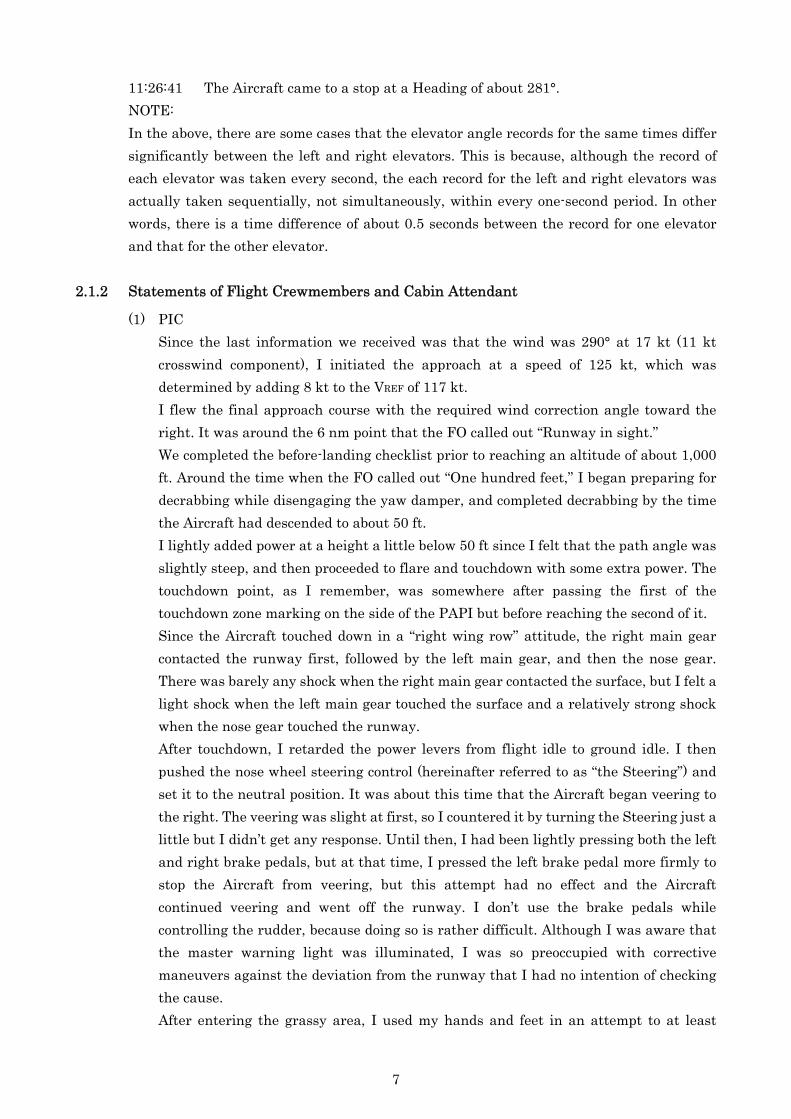
2.1.2 Statements of Flight Crewmembers and Cabin Attendant
(1) PIC Since the last information we received was that the wind was 290° at 17 kt (11 kt
crosswind component), I initiated the approach at a speed of 125 kt, which was determined by adding 8 kt to the VREF of 117 kt.
I flew the final approach course with the required wind correction angle toward the right. It was around the 6 nm point that the FO called out “Runway in sight.”
We completed the before-landing checklist prior to reaching an altitude of about 1,000 ft. Around the time when the FO called out “One hundred feet,” I began preparing for decrabbing while disengaging the yaw damper, and completed decrabbing by the time the Aircraft had descended to about 50 ft.
I lightly added power at a height a little below 50 ft since I felt that the path angle was slightly steep, and then proceeded to flare and touchdown with some extra power. The touchdown point, as I remember, was somewhere after passing the first of the touchdown zone marking on the side of the PAPI but before reaching the second of it.
Since the Aircraft touched down in a “right wing row” attitude, the right main gear contacted the runway first, followed by the left main gear, and then the nose gear. There was barely any shock when the right main gear contacted the surface, but I felt a light shock when the left main gear touched the surface and a relatively strong shock when the nose gear touched the runway.
After touchdown, I retarded the power levers from flight idle to ground idle. I then pushed the nose wheel steering control (hereinafter referred to as “the Steering”) and set it to the neutral position. It was about this time that the Aircraft began veering to the right. The veering was slight at first, so I countered it by turning the Steering just a little but I didn’t get any response. Until then, I had been lightly pressing both the left and right brake pedals, but at that time, I pressed the left brake pedal more firmly to stop the Aircraft from veering, but this attempt had no effect and the Aircraft continued veering and went off the runway. I don’t use the brake pedals while controlling the rudder, because doing so is rather difficult. Although I was aware that the master warning light was illuminated, I was so preoccupied with corrective maneuvers against the deviation from the runway that I had no intention of checking the cause.
After entering the grassy area, I used my hands and feet in an attempt to at least
7

recover the Aircraft’s straightforward direction to prevent from skidding and come to a stop as soon as possible, although I don’t remember exactly how I did it. While the Aircraft was running, I saw two ground lights; I probably managed to avoid hitting them. I then had a ditch in my view, which I also managed to pass over. The Aircraft ran up to the apron and, when I pressed the brake pedals, it came to a gentle stop despite my firm foot pressure.
Around the time when the Aircraft came to a stop, I saw a tire rolling forward from somewhere, but I couldn’t identify the origin. After the Aircraft stopped, I set the parking brake and placed the condition levers to the fuel cut-off positions to cut both engines.
I made a PA announcement to tell the passengers that the Aircraft was in an unintended stop in the present place because it had deviated from the runway due to difficulty in maintaining direction after landing and that the ground staff was going to take care of the disembarkation.
(2) FO After switching to manual control mode at an altitude of about 1,000 ft, we flew on the
normal approach course. We set the approach speed to 125 kt, as the last wind information we received from the Radio was 290° at 17 – 18 kt (12 kt crosswind component). As I remember, we flew a proper approach course and touched down without any problems at a point not significantly missing the touchdown zone. There was no significant turbulence up until the touchdown. The right main gear contacted the ground first under smooth touchdown control, I think.
After the touchdown, I took the control wheel upon the PIC’s “You have” instruction and used the right-bank aileron control while pushing the column forward. I’m not sure of the exact time after the touchdown, but I felt an unusual condition with the Aircraft; it seemed as if the Aircraft was veering to the right. In no time, the Aircraft began to slowly veer to the right and at or near the time when it subsequently deviated from the runway, the master warning light came on. I think it was the panel of the right engine oil pressure that turned on; nevertheless, I don’t remember whether or not I called out as I was preoccupied with the Aircraft’s deviation from the runway. The Aircraft ran on the grassy area as if it were sliding, and I think that I instinctively stepped on the brake pedals although I don’t know how hard I did that. Time went by extremely slowly and I may have been unduly upset.
I felt several small shocks when the Aircraft went over a ditch in the grassy area. The Aircraft then stopped gently just on the south end of the apron. When the Aircraft came to a stop, I saw a nose tire rolling forward.
(3) Cabin attendant We flew fairly smoothly without experiencing any shakes during the period from the
start of descent to the landing. The touchdown was also quite normal. Shortly after touchdown, I felt a light shock like one that would occur when the wheels run over stones. After a while the Aircraft returned to a normal roll, I felt light jerks twice or so. Having a feeling that the Aircraft was running straight but was sliding to the right, I
8

looked at a window and found that shreds of grass were sticking to it. I also felt a bouncing motion. I realized that this was because the Aircraft was running on a grassy area. When the Aircraft slowed down, there were a couple of rather large, but not violent, bounces. The Aircraft was getting much slower and finally came to a stop gently and smoothly.
After the Aircraft stopped, I stood up and checked the outside of the Aircraft, finding no damage to the Aircraft or smoke as far as I could see.
I walked down the cabin, checking the passengers for injuries or any other problems. They were all unhurt and calm. After this, the PIC made a situational announcement to the passengers.
2.1.3 Statements of Passengers
All the passengers’ statements have the following in common: The Aircraft landed normally, then veered to the right and ran into a grassy area while splashing muddy water on its right windows. As to the shocks experienced during the ground running, the forward cabin passengers felt greater shocks, whereas the aft cabin passengers felt milder shocks.
The serious incident occurred near the runway at Izumo Airport (latitude 35°24'49"N,
longitude 132°53'24"E), at about 11:26 on December 18, 2007. (See Figure 1 – Estimated Flight Route; Figure 2 – Touchdown Point and Ground Rolling
Condition; Figure 3 – DFDR Records; Photo 1 – Placement of Instruments and Panels; Photo 2 – Ditch on the Side of the Runway; Photo 3 – Serious Incident Aircraft; Photo 4 – Damaged Nose Gear; Photo 5 – Power Levers; Photo 6 – Nose Wheel Steering; and Attachment CVR Records.) 2.2 Injuries to Persons
No one was injured. 2.3 Damage to the Aircraft
2.3.1 Extent of Damage
Slightly damaged 2.3.2 Damage to the Aircraft Components
Nose landing gear: Wheels broken and right tire detached Right propeller: Dented
2.4 Other Damage
None
2.5 Personnel Information
(1) PIC Male, Age 58
9
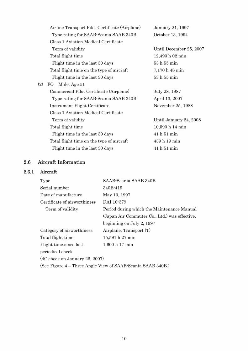
Airline Transport Pilot Certificate (Airplane) January 21, 1997 Type rating for SAAB-Scania SAAB 340B October 13, 1994 Class 1 Aviation Medical Certificate Term of validity Until December 25, 2007 Total flight time 12,493 h 02 min Flight time in the last 30 days 53 h 55 min Total flight time on the type of aircraft 7,170 h 48 min Flight time in the last 30 days 53 h 55 min (2) FO Male, Age 51 Commercial Pilot Certificate (Airplane) July 28, 1987 Type rating for SAAB-Scania SAAB 340B April 13, 2007 Instrument Flight Certificate November 25, 1988 Class 1 Aviation Medical Certificate Term of validity Until January 24, 2008 Total flight time 10,590 h 14 min Flight time in the last 30 days 41 h 51 min Total flight time on the type of aircraft 439 h 19 min Flight time in the last 30 days 41 h 51 min
2.6 Aircraft Information
2.6.1 Aircraft
Type SAAB-Scania SAAB 340B Serial number 340B-419 Date of manufacture May 13, 1997 Certificate of airworthiness DAI 10-379
Term of validity Period during which the Maintenance Manual (Japan Air Commuter Co., Ltd.) was effective, beginning on July 2, 1997 Category of airworthiness Airplane, Transport (T) Total flight time 15,591 h 27 min Flight time since last 1,600 h 17 min periodical check (4C check on January 26, 2007) (See Figure 4 – Three Angle View of SAAB-Scania SAAB 340B.)
10

2.6.2 Engines
No. 1 No. 2 Type GE CT7-9B GE CT7-9B Serial number E-785513 E-785732 Date of manufacture December 11, 1992 September 28, 1997 Total time in service 18,538 h 21 min 15,181 h 08 min Time in service since last periodical check (overhaul)
4,331 h 11 min 237 h 53 min
2.6.3 Weight and Balance
When the serious incident occurred, the Aircraft’s weight is estimated to have been 26,326 lbs and the position of the center of gravity is estimated to have been 22.7% mean aerodynamic chord (MAC), both of which are estimated to have been within the allowable limits (i.e., maximum landing weight of 28,000 lbs, and center-of-gravity range of 18–37.6% MAC based on the estimated Aircraft weight at the time of the serious incident). 2.6.4 Fuel and Lubricating Oil
The fuel used in the Aircraft was aviation fuel JET A-1 and the lubricating oil used was BPTO 2380. 2.7 Meteorological Information
Aeronautical weather observations for Izumo Airport around the time of the serious incident were as follows:
11:00 Wind direction 280°; Wind velocity 17 kt; Visibility 10 km or more Cloud: Amount 1/8, Type Cumulus, Ceiling 3,000 ft Amount 6/8, Type Cumulus, Ceiling 4,000 ft Temperature 11°C; Dew point −3°C Altimeter setting (QNH) 30.06 inHg 11:44 Wind direction 290°; Wind velocity 17 kt; Visibility 10 km or more Cloud: Amount 1/8, Type Cumulus, Ceiling 3,000 ft Amount 6/8, Type Cumulus, Ceiling 4,000 ft Temperature 11°C; Dew point −1°C Altimeter setting (QNH) 30.06 inHg
2.8 Information on DFDR and CVR
The Aircraft was equipped with a DFDR (P/N 980-4700-003) made by AlliedSignal of the United States of America and a CVR (P/N 2100-1020-00) made by L-3 Communications of the United States of America.
The DFDR and CVR retained a record of data from the time the Aircraft took off from Osaka International Airport to the time the Aircraft stopped after landing at Izumo Airport and the
11

occurrence of the serious incident. The time was determined by correlating the DFDR-recorded VHF transmission keying
signals with the NTT(Nippon Telegraph and Telephone Corporation) speaking clock recorded on the ATC communication records.
2.9 Information on the Serious Incident Site
2.9.1 Conditions of the Serious Incident Site
Tire marks identifiable as those of the Aircraft (nose gear, left and right main gear tires) were left on Runway 25. The marks started at about 680 m from the approach end of the runway and curved gently to the right, deviating from the runway at a point about 950 m from the approach end toward the grassy area. The tire marks continued curving to the right while still in the grassy area, then crossed Taxiway T2 and ran over a 110-cm-wide ditch ran parallel to the runway. The marks ran uninterrupted until they ended at the Aircraft’s stop position.
There was no significant difference in hue between the marks from the left and right main gear tires on the runway.
At the top of the ditch were strike marks that would have been caused when the nose and main gear tires hit the edges. Broken pieces of the nose wheels were scattered over the trail stretching from that point of the ditch in the direction of the Aircraft’s movement. The tire marks continued up to the apron, and scratch marks were left on the asphalt surface. The Aircraft came to a stop on the apron just north of Taxiway T1.
The Izumo Airport runway is 2,000 m long and 45 m wide, stretching in a magnetic direction of 247°. The airport’s navigation aid and other facilities were operating normally.
(See Figure 2 – Touchdown Point and Ground Running Conditions, and Photo 2 – Ditch on the Side of the Runway.) 2.9.2 Detailed Damage to the Aircraft
Both the left and right tires of the nose gear were punctured, and the right tire was detached from the wheel. While both wheels remained on the nose gear spindle, the tire-retaining flanges were cracked and chipped due to the tireless running.
The right nose gear tire had cracks on its sidewalls and tread, and the cracks on the tread reached the inside of the tire. All the tires had strike marks caused by the edges of the ditch as described in 2.9.1.
One of the right propeller blades had marks showing contact against a foreign object on its leading edge.
(See Photo 3 – Serious Incident Aircraft, and Photo 4 – Damaged Nose Gear.) 2.10 Operational Check on Aircraft Systems
(1) Brake and steering systems The hydraulic circuits for the Aircraft’s brake and steering systems exhibited neither
damage nor leakage and both systems functioned normally when operated from the cockpit.
12

(2) Flight controls The ailerons, rudder and elevators functioned normally when operated from the cockpit. (3) Propeller pitch The pitch of each side of propellers changed normally responding to the operation of the
condition levers and the corresponding power levers. (4) Engines Visual inspection of each engine’s compressor and turbine from both the air intake and
exhaust ends revealed no traces of foreign matter. When the engines were started, the related instruments indicated normal readings. When the power and condition levers were operated, the instruments did not show any abnormal reading; they indicated the correct torque and propeller speed values corresponding to the positions of these levers.
2.11 Aircraft Control Procedures and Other Matters Concerned
(1) The Company’s Airplane Operating Manual includes the following in Chapter 2, 2-8-3 LANDING ROLL as aircraft control procedures to be followed after landing. (Excerpts)
The Company’s Flight Training Guide also includes similar descriptions.
PF PNF - After confirming PNF callout (FI), lift the
power lever latches, move the power levers to GND idle and lower the nose wheels.
- After touchdown, promptly confirm the illumination of the FI STOP light and call out “FI.”
LP (Pilot in Left Seat) RP (Pilot in Right Seat) - After the nose wheels have tou hed
down, promptly call out “You have,” and switch directional control to nose steering.
c
- Call out “I have,” and hold the control
wheel. - Apply necessary brakes. - Control the aircraft so as to maintain
the runway centerline.
- Confirm that the BETA lights are on
and use r verse thrust as required. e
e
- If reverse power has been used, move the power levers back to GND idle.
- When the BETA lights are on, call out “BETA.”
- Upon r aching 60 kt, call out “Sixty.”
(Intentionally omitted.) (Intentionally omitted.)
13

NOTES: 1. If th FI STOP ligh doe not com on, call out “No FI,” and pull the FI STOP OVRD
(override) knob. e t s e
e
c
e
r
ec
2. If a BETA light does not come on, call out “No BETA … (left or right).”
(2) Similarly to (1) above, Chapter S2, S2-2-9 LANDING of the Company’s Airplane Operating Manual also includes the following post-landing procedures. (Excerpts)
The Company’s Flight Training Guide includes similar descriptions. After touchdown, the PNF shall promptly confirm that the FI STOP light is on and call
out “FI.” (Skipped) After confirming PNF callout (FI), PF lifts the power l ver latches, moves the power
levers into ground idle and lowers the nose wheel. After touchdown, LP puts hand on NWS, ready to use. After the nose wheels have touched down, LP promptly calls out “You have.” RP calls out “I have” and takes over maneuvering. (LP swit hes directional control to nose steering.) When beta lights are on RP calls “Beta light” and LP applies reverse power as desired. If a beta light fails to come on, RP calls “Negative beta light ……….(left/right)”.
Aileron into wind, if strong crosswind. At 60 KIAS PNF calls “60 knots” and PF thenadvances PL to b out of reverse at 50 KIAS. CAUTION: 1. If the aircraft veers to one side during the landing roll, go out of reve se
and, if necessary, use forward power. Straighten the landing roll by means of rudder, nose wheel steering and differential braking. Then use reverse power as required.
(3) The Company’s Airplane Operating Manual includes the following descriptions in
Chapter 2, 2-1-1 GENERAL INFORMATION 1. (Excerpts) The master warning and master caution lights shall be used as the primary means of
being notified of systems’ abnormal conditions. When the master warning and caution lights come on, p rform the appropriate
emergen y/abnormal checklist. (4) The Company’s Airplane Operating Manual includes the following in Chapter 4, 4-1-1
GENERAL INFORMATION 2. If any of the master warning and/or caution lights come on, check the central warning
panel to identify the warned system(s), call out the warned condition(s), and reset themaster warning and/or caution lights promptly.
14
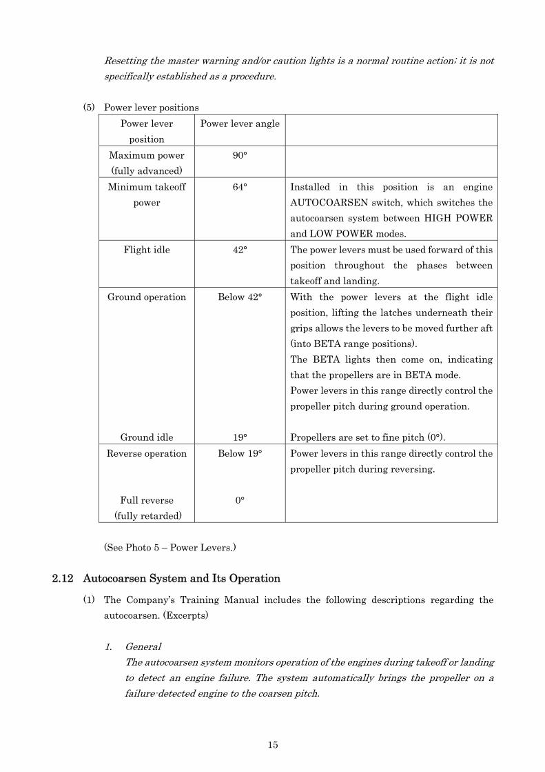
Resetting the master warning and/or caution lights is a normal routine action; it is not specifically established as a procedure.
(5) Power lever positions
Power lever position
Power lever angle
Maximum power (fully advanced)
90°
Minimum takeoff power
64° Installed in this position is an engine AUTOCOARSEN switch, which switches the autocoarsen system between HIGH POWER and LOW POWER modes.
Flight idle 42° The power levers must be used forward of this position throughout the phases between takeoff and landing.
Ground operation
Ground idle
Below 42°
19°
With the power levers at the flight idle position, lifting the latches underneath their grips allows the levers to be moved further aft (into BETA range positions). The BETA lights then come on, indicating that the propellers are in BETA mode. Power levers in this range directly control the propeller pitch during ground operation. Propellers are set to fine pitch (0°).
Reverse operation
Full reverse (fully retarded)
Below 19°
0°
Power levers in this range directly control the propeller pitch during reversing.
(See Photo 5 – Power Levers.)
2.12 Autocoarsen System and Its Operation
(1) The Company’s Training Manual includes the following descriptions regarding the autocoarsen. (Excerpts)
1. General The autocoarsen system monitors operation of the engines during takeoff or landing
to detect an engine failure. The system automatically brings the propeller on a failure-detected engine to the coarsen pitch.
15

In the above description, the “coarsen pitch” means a condition of the propeller in which its blades are set to an angle nearly parallel to the air flow (about 55° relative to the propeller rotating plane) in order to reduce the drag and thus makes aircraft control operations easier.
The Company’s Airplane Operating Manual includes the following descriptions in Chapter S1, S1-17 POWER PLANT 6, PROPELLER CONTROL SYSTEM. (Excerpts)
(5) AUTOCOARSEN SYSTEM The autocoa sen system is installed to achieve a fast reduction in windmilling drag
during takeoff, approach and go-around in case of engine failure. The system also responds to temporary engine malfunctions such as momentary fuel or air flow interruption.
r
r
c
The system continues to monitor engine parameters after an autocoarsen, and it uncoarsens the p opeller if both TRQ and P3 return to above threshold values.
(Skipped) The AUTO COARSEN ON/OFF switch must be set to ON position to a hieve any
indication or autocoarsen function. The system has two distinct modes of operation: LOW POWER and HIGH POWER,
modes. The system monitors power lever positions and engine parameters as below: PLA - Power Lever Angle quadrant position. PLA 64 degrees is the minimum takeoff power PL position; Ng - Gas generator speed (%); Ne - Starter/generator speed (%); TRQ - Torque (%); P3 - Compressor discharge pressure (psi).
(Skipped) a. LOW POWER mode
This status is indicated by an AUTOCOARS LOW “armed” light if: - PLA < 64 degrees (one or both PL’s); and - Ng > 55% (both engines); and - Ne > 60% (both engines). Autocoarsen occurs if (AUTOCOARS LOW light does not need to be on): - Ng < 55% (failed engine); and - Ne < 60% (failed engine); and - Ng > 55 (good engine). (PLA is irrelevant).
b. HIGH POWER mode This status is indicated by an AUTOCOARS HIGH “armed” light if: - PLA > 64 degrees (both PL’s); and - TRQ > 50% (both engines); and - P3 > 120 psi (both engines).
16

Autocoarsen occurs if (AUTOCOARS HIGH light does not need to be on): - PLA > 64 degrees (both PL’s); and - TRQ > 50% (good engine); and - TRQ < 50% (failed engine); and - TQR differential > 25% (between engines); and - P3 < 120 psi (failed engine).
(2) P3 sensor switches The Aircraft was equipped with P3 sensor switches (P/N: 9303051-0022, Serial No.: 1133
[left engine] and 1444 [right engine]) made by ITT Aerospace Controls (Neo-Dyn) of the Unites States of America.
According to SAAB, the standard threshold pressure for tripping these switches is 120 psi, whereas each sensor switch has a non-sensing zone equivalent to 25 psi (maximum) above the standard threshold pressure when the pressure is rising, while it trips at the standard threshold pressure with a tolerance of ±10 psi when the pressure is dropping.
2.13 Tests and Research for Fact Finding
2.13.1 Ground Roll Test
After the damaged nose gear wheels of the Aircraft were replaced, no anomalies were confirmed through a visual inspection on the nose gear. For that reason, the following ground roll tests were conducted on Izumo Airport runway on December 21, 2007.
(1) Making a brief stop by applying the brakes immediately after starting the roll-off. Turning the Aircraft left and right on the apron by using the Steering to the full extent
in both directions. (2) Sequential execution of the following tests (① to ④) while running the Aircraft on the
runway at about 45 kt with the power levers set to the flight idle position. ① Availability of full reverse power ② Zigzag running by using the Steering ③ Operation of the brakes ④ Maintaining and changing the direction by using the rudder (3) Maintaining and changing direction by using the rudder with the engine torque at
40–50% (power levers slightly advanced from the flight idle position), flaps at 20° and rolling speed at 80 kt.
The results of all the above ground roll tests (1) to (3) were successful, showing that all the mentioned systems worked normally.
The visual inspection of the nose gear after the ground roll test revealed no anomalies. 2.13.2 Operational Test on the Autocoarsen System
The DFDR records indicate that the left engine torque rose sharply while the left propeller speed dropped drastically in the period between 11:26:14 and 11:26:15. These changes are remarkably similar to occurrence of autocoarsen, so the relevant parameters are shown in the table below.
17

The parameters indicated on each time line in the table were not taken synchronously but rather at different points within a one-second period. PLA/L
(°) PLA/R
(°) TRQ/L
(%) TRQ/R
(%) TRQ
differential(%)
P3/L(psi)
P3/R(psi)
Np/L (rpm)
Np/R (rpm)
Ng/L(%)
Ng/R(%)
11:26:11 49.7 60.3 15.3 32.6 17.3 101.3 139.4 1381 1399 84.2 88.911:26:12 55.3 63.9 15.5 38.9 23.4 107.4 151.2 1388 1400 85.6 90.611:26:13 58.7 69.0 19.7 48.8 29.1 121.7 171.3 1395 1407 87.7 92.511:26:14 60.7 57.8 27.2 50.4 23.2 132.3 161.4 1387 1377 89.1 90.811:26:15 58.3 49.0 55.1 38.8 16.3 133.7 131.5 957 1359 89.3 87.4NOTE: PLA: Power Lever Angle
TRQ: Torque P3: Compressor Discharge Pressure Np: Propeller RPM Ng: Gas Generator Speed
An operation test on the autocoarsen system was conducted using the Aircraft, considering
it highly probable that, in the period between 11:26:13 and 11:26:14, the conditions for autocoarsen activation in HIGH POWER mode as described in 2.12 (1) might have been met and the left propeller might have consequently been brought to the coarsen pitch.
In the test, the power levers were operated in such a manner that there was a positional difference between their grips in the amount necessary to create torque differential of about 25% between the left and right engines. In order to avoid probable overloading of an engine when its propeller was feathered by autocoarsen activation, a special control was incorporated in the test, i.e., the engine’s power would be reduced upon confirming autocoarsen activation (indicated by a sharp rise in torque and a drastic drop in propeller speed immediately after the extinction of the AUTOCOARS HIGH armed light).
The DFDR records derived from the test are shown below. Elapsed
time (sec.)
PLA/L (°)
PLA/R(°)
TRQ/L (%)
TRQ/R(%)
TRQ differential
(%)
P3/L(psi)
P3/R(psi)
Np/L (rpm)
Np/R (rpm)
Ng/L(%)
Ng/R(%)
0 61.8 71.9 37.0 66.6 29.6 129.5 188.8 1,120 1,358 88.9 93.71 61.9 71.9 37.7 67.5 29.8 130.7 190.6 1,122 1,365 89.2 93.82 61.9 71.7 57.6 68.4 10.8 166.0 191.5 926 1,368 92.3 93.83 61.3 71.4 53.2 67.8 14.6 146.4 191.5 995 1,371 89.8 93.94 61.1 71.2 44.9 68.6 23.7 138.8 190.4 1,141 1,373 89.2 93.9
As the time elapsed from the 1st second to the 2nd second, the left engine torque rose
sharply from 37.7% to 57.6% while the left propeller speed dropped drastically from 1,122 to 926 rpm, indicating autocoarsen activation in HIGH POWER mode.
The autocoasen activation conditions were met in this one-second period as verified by the following:
18

① The power lever angles recorded on the DFDR differed slightly from the actual angles. The recorded angle of the left power lever is actually about 2° less than 64°, the angle that should theoretically be reached for activation of the autocoarsen. Nevertheless, the system is designed to switch itself from LOW POWER mode to HIGH POWER mode by means of the mode change switch installed at the 64° position of the power lever, and the switching to HIGH POWER mode actually did take place at that time.
② The torque (left engine <50%, right engine ≥50%) met the autocoarsen activation condition.
③ The torque differential between the engines (≥25%) met the autocoarsen activation condition.
④ The recorded left engine P3 was 130.7 psi, which satisfied the pressure requirement for the P3 sensor switch trip threshold (i.e., 145 psi maximum) for pressure rising conditions as described in 2.12 (2).
2.13.3 Verification on Simulator
Using a Level-D simulator of the same aircraft type, the simulation of the Aircraft’s conditions at the time of occurrence of the serious incident that the left engine was stopped just before landing and its propeller was feathered, was carried out. Verification through the simulation brought about the following findings:
(1) The speed (in knots) down to which the Aircraft would have been able to run straight ahead by using only the rudder, was verified. The results were as follows: ① With the power levers at the flight idle position, running straight ahead was
possible down to 40 kt. ② With the power levers at the ground idle position, running straight ahead was
possible down to 50 kt. ③ With the power levers at the full reverse position, running straight ahead was
possible down to 90 kt. (2) Whether or not the Aircraft would have been able to run straight ahead using only the
steering while varying the elevator positions, was verified. The results were as follows: ① With the control column pushed fully forward, running straight ahead was
possible when the power levers were retarded to any position past the flight idle position.
② As in ① above, it was fully possible to run straight ahead when the control column was placed roughly halfway forward (about 10°) from the released position after landing.
③ With no force applied on the control column, a veer to the right began as soon as the power levers were retarded past the flight idle position, disabling any further straight-ahead running.
(3) Directional control using only the brakes during ground rolling was verified. Running straight ahead was possible by using only the brakes with the power levers retarded to any position past the flight idle position.
19

2.14 Additional Information
2.14.1 The Company’s Airplane Operating Manual (1) includes the following descriptions in Chapter 1, 1-5-4 TAKEOFF/LANDING LIMITATIONS AND MAXIMUM CROSSWIND LIMITATION FOR DIFFERENT RUNWAY CONDITIONS.
3. Maximum crosswind limitation The maximum (mean) crosswind limitation applied to takeoff and landing shall be as
specified below for different runway conditions. However, short-time surpassing of the limita ion is permissible after the start of
takeoff o after the decision of landing.t
r
c f
(1) On a dry or wet runway, the maximum (mean) crosswind limitation shall be 25 kt. NOTE: The maximum crosswind omponent (mean wind) demonstrated by the
airplanes in its type certi ication is 35 kt for both takeoff and landing on a dry runway.
2.14.2 The Company’s Past Experience with Autocoarsen Activation
The Company has been operating the SAAB-Scania SAAB 340B airplanes since 1992. However, prior to this serious incident, there had been no autocoarsen activation at the time of touchdown or in consequence of flight control operations, so the flight crewmembers of these airplanes had not experienced any situations like the one encountered in this serious incident.
Both the PIC and FO had received simulator training on landing with one engine inoperative, which requires basically the same control techniques as those applied when autocoarsen has been occurred. 2.14.3 Rudder and Elevator Angles
The Company’s Training Manual includes the following descriptions: (1) Rudder Maximum angle ±27.5° Maximum angle (150 KEAS) ±15° Maximum angle (200 KEAS) ±6.3° (2) Elevators Maximum angle 18° (down) Maximum angle 22° (up)
20

3. ANALYSIS 3.1 Airman Competence Certificate and Aviation Medical Certificate
The PIC and the FO both held valid airman competence certificate and valid aviation medical certificate. 3.2 Airworthiness Certificate
The Aircraft had a valid airworthiness certificate and had been maintained and inspected as prescribed. 3.3 Meteorological Conditions
The wind at the time of the serious incident as reported by the Radio was 300° at 17 kt. Its crosswind component was about 13 kt, i.e., below the cross wind limitation of 25 kt as described in 2.14, and thus it is considered highly probable that the crosswind component, despite its weathercock effect, did not directly contribute to the occurrence of the serious incident when considering the performance of the Aircraft. 3.4 Autocoarsen Activation and Its Timing
(1) Based on the descriptions in 2.13.2 ①, it is considered probable that the actual angles of the power levers between 11:26:13 and 11:26:14 met the autocoarsen activation condition (PLA > 64 degrees).
(2) During the period between 11:26:13 and 11:26:14, the left engine torque was below 50% while the right engine torque was above 50%. At 11:26:13, the torque differential between the engines was 29.1% although at 11:26:14 it was 23.2%, a level slightly below the autocoarsen activation threshold. It is therefore considered probable that the torque differential met the autocoarsen activation condition in this 11:26:13 to 11:26:14 period.
(3) In the period between 11:26:12 and 11:26:14, the right engine P3 rose above 150 psi while the left engine P3 remained below 145 psi. It is therefore considered probable that the P3 sensor switch trip threshold (i.e., 145 psi maximum) for pressure rising condition described in 2.12 (2) was met.
As described above, it is considered highly probable that around the period between 11:26:13 and 11:26:14, the Aircraft’s left engine met the autocoarsen activation conditions in HIGH POWER mode. This is also supported by a sharp rise in torque and a drop in propeller speed of the left engine in addition to a sound suggesting decreased propeller speed, which were recorded for this period by the DFDR and CVR, respectively. It is therefore considered highly probable that the left propeller was brought to the coarsen pitch at that timing. 3.5 Flight Crewmembers’ Understanding of the Autocoarsen
As described in 2.12, the Company’s Airplane Operating Manual, an everyday reference for flight crewmembers, and the Flight Training Guide, a textbook for flight training, both explain the autocoarsen in detail. It is therefore considered highly probable that the flight crewmembers of the
21

Aircraft had knowledge about the autocoarsen. However, because the Airplane Operating Manual describes that the autocoarsen system is
installed in case of engine failure and neither the PIC nor the FO mentioned the possibility of autocoarsen activation in 2.1.2 (1) and (2), it is considered probable that the crewmembers had not realized that the autocoarsen might have been activated as a result of the specific control inputs they made. 3.6 Situation of the Aircraft and Control Operations by the Flight Crewmembers
3.6.1 Prior to Touchdown
(1) Based on the descriptions in 2.1.1, it is considered highly probable that the Aircraft was flying normally on an approach course to Runway 25 at Izumo Airport.
At about 11:26:07, immediately after the FO called out “Fifty,” the power levers, which until then were being operated almost evenly, began to be retarded at significantly different rates (the left lever was moved more than the right lever). Since pilots normally do not operate the power levers in that manner, and thus it is hardly conceivable that their normal control of the levers would result in that great an angular difference, it is considered probable that the PIC operated the power levers that way in order to align the Aircraft with the runway centerline in the right crosswind.
(2) It is considered highly probable that the PIC then advanced the power levers to correct the Aircraft’s approach path angle that had become steeper due to the decreased engine power.
Regarding the approach path angle becoming steeper, the PIC said that he “felt that the path angle was slightly steep.” in his statement described in 2.1.2 (1). However, since the change in approach path angle coincided with the retardation of the power levers, it is considered probable that the PIC’s operation of the power levers also contributed to the change in approach path angle.
(3) Regarding the power lever advancement made to correct the approach path angle, the PIC stated that he “lightly added power.” However, because the amount of lever advancement was so large that the minimum takeoff power was surpassed, it is considered highly probable that the angular difference between the left and right power levers then became greater (as much as about 10°) than it had been in the state at (1).
3.6.2 Touchdown
(1) The DFDR data described in 2.1.1 show peaks in both the vertical and longitudinal acceleration at about 11:26:16, while the data for that time shows a negative pitch angle. Also, it is considered probable that the Aircraft made a normal landing with touchdown beginning with the main gears as described in both the crewmember and passenger statements. It is therefore considered highly probable that the nose gear touched down at about 11:26:16, but the main gears touched down before that time (between around 11:26:13 and 11:26:14). It is considered highly probable that, immediately after the PIC performed the control described in 3.6.1 (3), that is, at about
22
the same time as the main gears touched down, the left propeller was brought to the coarsen pitch.
As described in 2.1.1, the CVR records corresponding to 11:26:15 contains a sound suggesting a drop in propeller speed. It is considered highly probable that, had the flight crewmembers noticed the sound and checked the engine instruments, they would have been able to recognize the drop in speed of the left propeller.
Since the engines were found to be free of anomalies and the autocoarsen activation conditions had been met as described in 3.4, it is considered highly probable that the PIC’s power lever operation caused the left propeller to be brought to the coarsen pitch.
It is considered highly probable that the coarsen pitch activation would not have taken place if there had been no angular difference between the power levers even when the minimum takeoff power had been exceeded, whereas, unless the minimum takeoff power had not been exceeded, the coarsen pitch activation would not have occurred even if there had been angular difference between the power levers.
(2) Since the engines were found to be free of abnormalities, it is considered probable that the coarsen pitch activation should have been cancelled if the torque and P3 had risen above the thresholds. However, it is considered probable that cancellation of the coarsen pitch activation did not actually take place because the power levers were retarded to the flight idle position so early that the thresholds were never reached.
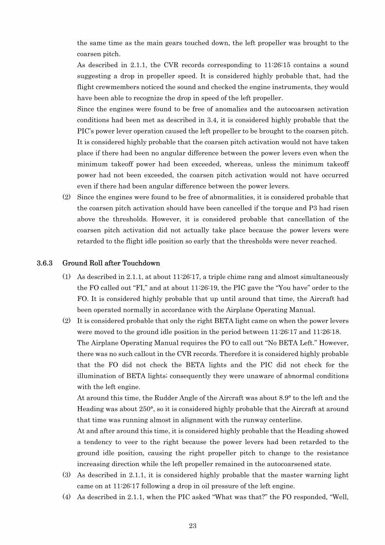
3.6.3 Ground Roll after Touchdown
(1) As described in 2.1.1, at about 11:26:17, a triple chime rang and almost simultaneously the FO called out “FI,” and at about 11:26:19, the PIC gave the “You have” order to the FO. It is considered highly probable that up until around that time, the Aircraft had been operated normally in accordance with the Airplane Operating Manual.
(2) It is considered probable that only the right BETA light came on when the power levers were moved to the ground idle position in the period between 11:26:17 and 11:26:18.
The Airplane Operating Manual requires the FO to call out “No BETA Left.” However, there was no such callout in the CVR records. Therefore it is considered highly probable that the FO did not check the BETA lights and the PIC did not check for the illumination of BETA lights; consequently they were unaware of abnormal conditions with the left engine.
At around this time, the Rudder Angle of the Aircraft was about 8.9° to the left and the Heading was about 250°, so it is considered highly probable that the Aircraft at around that time was running almost in alignment with the runway centerline.
At and after around this time, it is considered highly probable that the Heading showed a tendency to veer to the right because the power levers had been retarded to the ground idle position, causing the right propeller pitch to change to the resistance increasing direction while the left propeller remained in the autocoarsened state.
(3) As described in 2.1.1, it is considered highly probable that the master warning light came on at 11:26:17 following a drop in oil pressure of the left engine.
(4) As described in 2.1.1, when the PIC asked “What was that?” the FO responded, “Well,
23
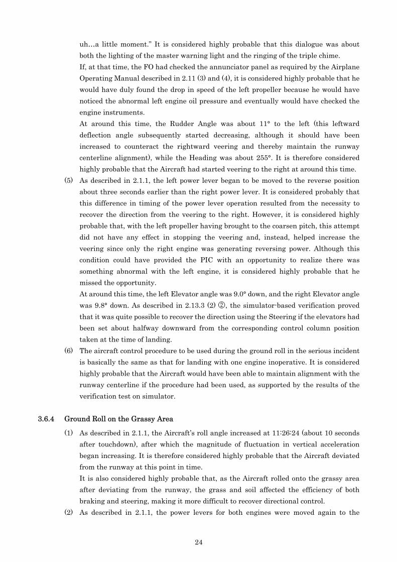
uh…a little moment.” It is considered highly probable that this dialogue was about both the lighting of the master warning light and the ringing of the triple chime.
If, at that time, the FO had checked the annunciator panel as required by the Airplane Operating Manual described in 2.11 (3) and (4), it is considered highly probable that he would have duly found the drop in speed of the left propeller because he would have noticed the abnormal left engine oil pressure and eventually would have checked the engine instruments.
At around this time, the Rudder Angle was about 11° to the left (this leftward deflection angle subsequently started decreasing, although it should have been increased to counteract the rightward veering and thereby maintain the runway centerline alignment), while the Heading was about 255°. It is therefore considered highly probable that the Aircraft had started veering to the right at around this time.
(5) As described in 2.1.1, the left power lever began to be moved to the reverse position about three seconds earlier than the right power lever. It is considered probably that this difference in timing of the power lever operation resulted from the necessity to recover the direction from the veering to the right. However, it is considered highly probable that, with the left propeller having brought to the coarsen pitch, this attempt did not have any effect in stopping the veering and, instead, helped increase the veering since only the right engine was generating reversing power. Although this condition could have provided the PIC with an opportunity to realize there was something abnormal with the left engine, it is considered highly probable that he missed the opportunity.
At around this time, the left Elevator angle was 9.0° down, and the right Elevator angle was 9.8° down. As described in 2.13.3 (2) ②, the simulator-based verification proved that it was quite possible to recover the direction using the Steering if the elevators had been set about halfway downward from the corresponding control column position taken at the time of landing.
(6) The aircraft control procedure to be used during the ground roll in the serious incident is basically the same as that for landing with one engine inoperative. It is considered highly probable that the Aircraft would have been able to maintain alignment with the runway centerline if the procedure had been used, as supported by the results of the verification test on simulator.
3.6.4 Ground Roll on the Grassy Area
(1) As described in 2.1.1, the Aircraft’s roll angle increased at 11:26:24 (about 10 seconds after touchdown), after which the magnitude of fluctuation in vertical acceleration began increasing. It is therefore considered highly probable that the Aircraft deviated from the runway at this point in time.
It is also considered highly probable that, as the Aircraft rolled onto the grassy area after deviating from the runway, the grass and soil affected the efficiency of both braking and steering, making it more difficult to recover directional control.
(2) As described in 2.1.1, the power levers for both engines were moved again to the
24
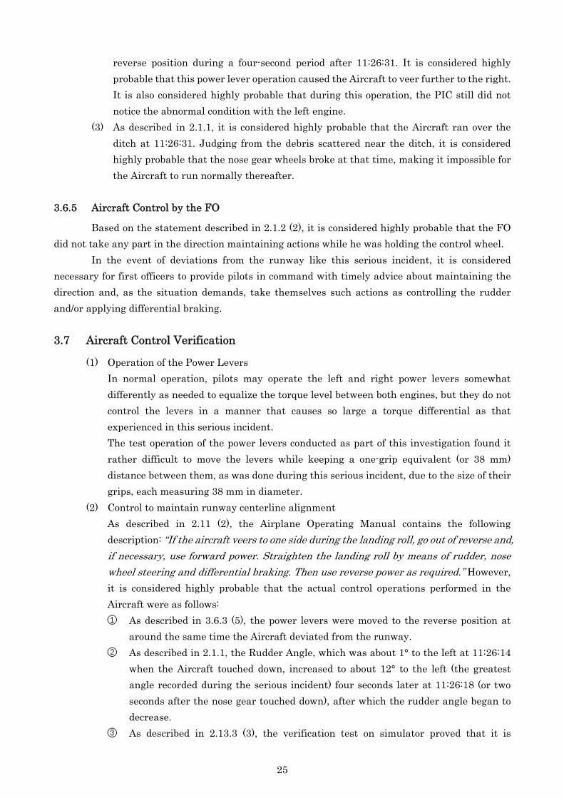
reverse position during a four-second period after 11:26:31. It is considered highly probable that this power lever operation caused the Aircraft to veer further to the right. It is also considered highly probable that during this operation, the PIC still did not notice the abnormal condition with the left engine.
(3) As described in 2.1.1, it is considered highly probable that the Aircraft ran over the ditch at 11:26:31. Judging from the debris scattered near the ditch, it is considered highly probable that the nose gear wheels broke at that time, making it impossible for the Aircraft to run normally thereafter.
3.6.5 Aircraft Control by the FO
Based on the statement described in 2.1.2 (2), it is considered highly probable that the FO did not take any part in the direction maintaining actions while he was holding the control wheel.
In the event of deviations from the runway like this serious incident, it is considered necessary for first officers to provide pilots in command with timely advice about maintaining the direction and, as the situation demands, take themselves such actions as controlling the rudder and/or applying differential braking. 3.7 Aircraft Control Verification
(1) Operation of the Power Levers In normal operation, pilots may operate the left and right power levers somewhat
differently as needed to equalize the torque level between both engines, but they do not control the levers in a manner that causes so large a torque differential as that experienced in this serious incident.
The test operation of the power levers conducted as part of this investigation found it rather difficult to move the levers while keeping a one-grip equivalent (or 38 mm) distance between them, as was done during this serious incident, due to the size of their grips, each measuring 38 mm in diameter.
(2) Control to maintain runway centerline alignment As described in 2.11 (2), the Airplane Operating Manual contains the following
description: “If the aircraft veers to one side during the landing roll, go out of reverse and, if necessary, use forward power. Straighten the landing roll by means of rudder, nosewheel steering and differential braking. Then use rev rse power as requi ed.” However, it is considered highly probable that the actual control operations performed in the Aircraft were as follows:
e r
① As described in 3.6.3 (5), the power levers were moved to the reverse position at around the same time the Aircraft deviated from the runway.
② As described in 2.1.1, the Rudder Angle, which was about 1° to the left at 11:26:14 when the Aircraft touched down, increased to about 12° to the left (the greatest angle recorded during the serious incident) four seconds later at 11:26:18 (or two seconds after the nose gear touched down), after which the rudder angle began to decrease.
③ As described in 2.13.3 (3), the verification test on simulator proved that it is
25

possible to keep rolling straight ahead using only the brakes. On the other hand, the tire marks left on the runway indicate neither a difference between the left and right tires nor an obvious change in their track that was significant enough to suggest strong application of the left main gear brakes, so the left main gear brakes were not strongly applied.
④ As described in 2.13.3 (2), pushing the control column forward after landing enables the Steering to control the direction effectively since this operation causes the nose gear to be forced against the runway surface.
As described in 2.1.1, at 11:26:19, the PIC gave the “You have” order to the FO. From that time on, the PIC started operating the Steering while the FO started controlling the elevators.
The Elevator Angles had been 1.9° down up to then, but they increased to about 9° and subsequently to about 12.6°, the maximum elevator angles in the period before the Aircraft’s deviation from the runway. It is therefore considered possible that the elevators were lowered sufficiently, but the Steering operation was insufficient.
26

4. PROBABLE CAUSE It is considered highly probable that this serious incident occurred through the following causal
chain: While the left propeller of the Aircraft was brought to the coarsen pitch almost simultaneously with touchdown causing the Aircraft to veer to the right during its subsequent landing roll, no necessary procedures were taken to stop the veering and furthermore to recover the directional control, which resulted in the Aircraft deviating from the runway, the nose gear being broken, and eventually the Aircraft being unable to ground roll for itself.
With regard to the left propeller having been brought to the coarsen pitch, it is considered highly probable that the power lever operations that were performed prior to touchdown caused the autocoarsen to be activated.
It is considered highly probable that the nose gear was broken when it hit the ditch that runs parallel to the runway.
27

5. REFERENTIAL MATTERS
In response to the Aircraft and Railway Accidents Investigation Commission’s report, “Serious Incident on the SAAB-Scania SAAB 340B, JA001C, Operated by Japan Air Commuter Co., Ltd. (Interim Report)”, the Company took the following measures:
1. On February 7, 2008, the Company issued a Crew Department Manager’s Notice addressed to the flight crewmembers of the SAAB 340B airplanes, intending to increase their awareness through reading the interim report.
2. In order to familiarize SAAB 340B airplane flight crewmembers (66 pilots) with the details of the interim report, the Company held sessions during the period of February 8 to February 21, 2008, in which its flight technical staff explained the contents of the report.
3. Education for the flight crewmembers (1) During the period of March 10 to April 9, 2008, the Company held timeliness-based
classroom training sessions on the autocoarsen system, featuring the four areas listed below, for SAAB 340B airplane flight crewmembers to prevent the recurrence of similar events. a. Actions to be taken upon activation of autocoarsen b. Stabilized approach and go-around policy c. Smooth operation of the power levers d. HYD Press operation to ensure the effectiveness of the Steering
(2) The Company decided to provide SAAB 340B airplane flight crewmembers with a classroom sessions on the autocoarsen system (the same contents as in (1)) and simulator-based practical lessons adding regular training programs in and after 2008.
28

N
Shimane Prefecture
Izumo Airport
Wind :300°/17kt (informed by Izumo tower)
Topographical map of 1/25,000 published by the Geographical Survey Institute
Figure 1 Estimated Flight Route
500 1km500m0
29
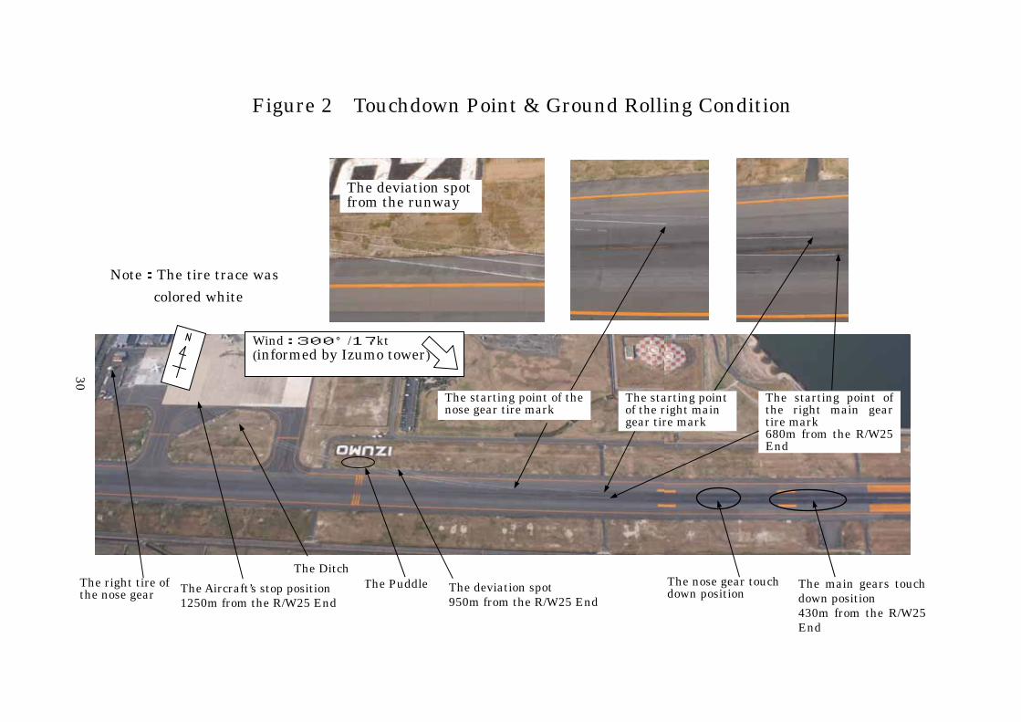
Note:The tire trace was colored white
The starting point of the nose gear tire mark
The right tire ofthe nose gear
Wind:300°/17kt(informed by Izumo tower)
The main gears touch down position 430m from the R/W25 End
The nose gear touchdown position
The Puddle The deviation spot 950m from the R/W25 End
The Aircraft’s stop position 1250m from the R/W25 End
The starting point of the right main gear tire mark 680m from the R/W25 End
The starting pointof the right main gear tire mark
The Ditch
Figure 2 Touchdown Point & Ground Rolling Condition
The deviation spot from the runway
30

31
Figure 3 DFDR Records

Figure 4
340B
21.4
7.00
19.73
32
Unit::m
Three Angle View of SAAB-SCANIA SAAB
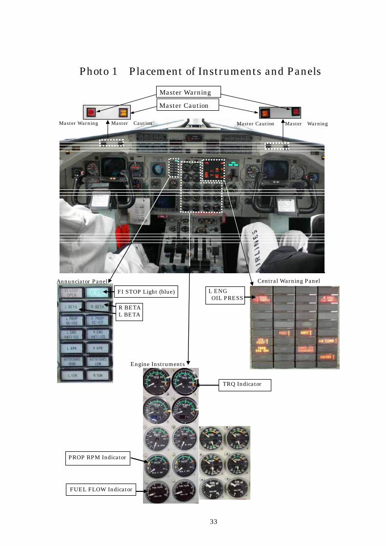
Photo 1 Placement of Instruments and Panels
Master Warning
Master Caution
Engine Instruments
Master Warning Master Caution Master Caution Master Warning
Annunciator Panel Central Warning Panel L ENG OIL PRESS
FI STOP Light (blue)
R BETA L BETA
TRQ Indicator PROP RPM Indicator
FUEL FLOW Indicator
33
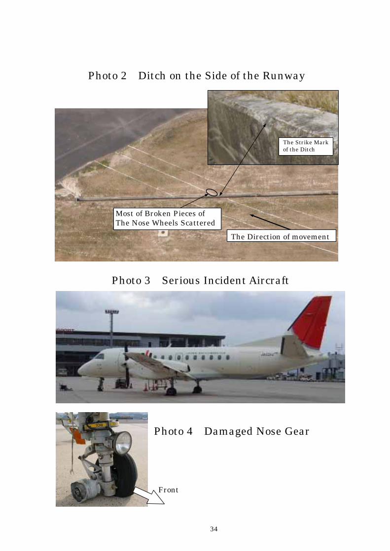
Photo 2 Ditch on the Side of the Runway
The Strike Markof the Ditch
The Direction of movement
Most of Broken Pieces of The Nose Wheels Scattered
Photo 3 Serious Incident Aircraft
Photo 4 Damaged Nose Gear
Front
34

Photo 5 Power Levers
Power Levers
Power Lever Latch
Maximum power: 90゜
Flight Idle: 42°
Ground Idle: 19°
Full Reverse: 0°
Rear
Front
Photo 6 Nose Wheel Steering
Left Panel Nose Wheel Steering
35

Attachment CVR Records
JST PF (Captain) PM (Co-pi) Area Mike
11:24:33 Landing Clearance
11:24:34 Received
11:24:44 One Thousand
11:24:45 Check
11:25:18 Five Hundreds
(oral call-out)
11:25:28 Five Hundreds
11:25:29 Stabilized
11:26:03 Hundred
11:26:05 Yaw Damper OFF
11:26:06 Fifty
11:26:07 Roger
11:26:15
The sound just like the
propeller speed was
dropping.
11:26:17 FI Triple Chime
11:26:19 You have
11:26:20 What was that? Single Chime
11:26:21 Well, uh…a little moment.
11:26:22 Triple Chime
11:26:24 Aaa.
11:26:25 What happened? Aa. Starting noise
11:26:27
11:26:28 Uaaa. Triple Chime
11:26:32 Uaaa. A big bang
11:26:33 A big bang
11:26:34 A big bang
11:26:37 What happened?
11:26:39 Uaaa.
11:26:41 Engine shut doun.
11:26:42 Roger.
11:26:45 Triple Chime
11:26:48 What happened?
11:26:49 I have no idea, this turned on.
11:27:01 Contact company radio.
11:27:02 Yes.
11:27:09 Contact tower.
11:27:17 Izumo tower, Izumo radio, JAC2345
11:27:20 (Izumo Radio) 2345, go ahead.
11:27:22 We could not maintain the direction
on the runway, and also the brakes
did not work normally. Therefore
we came to a lamp and at last were
able to stop. I stopped engines
and I would like to put off
passengers at this place.
11:27:43 (Izumo Radio) JAC2345、Roger.
36