AI based Direct Torque Fuzzy Control of AC Drives.pdf
12
International Journal of Electronic Engineering Research ISSN 0975 - 6450 Volume 1 Number 3 (2009) pp. 233–244 © Research India Publications http://www.ripublication.com/ijeer.htm AI based Direct Torque Fuzzy Control of AC Drives 1 Jagadish H. Pujar and 2 S.F. Kodad 1 Research S cholar (J NTU, Hyderabad) & Faculty, Department of EEE, BVB College of Engg. & Tech., Hubli, India E-mail: j hpujar@bv b.edu 2 Professor & Head, Department of EEE, Aurora’s Engineering College, Hyderabad, India E-mail: ko dadsf@re diffmail.c om Abstract Fuzzy logic is recently getting increasing emphasis in soft control applications. This paper presents an application of fuzzy logic to control the speed of an AC drive system is proposed for space vector pulse width modulated (SVPWM) voltage source inverter-fed induction motor drive. This paper presents the results of an investigation into the suitability of a Direct Torque Fuzzy Control (DTFC) method for an induction motor drive system. Direct torque control is known to produce quick and robust response in AC drive system. However during steady state, torque, flux and current ripple occurs. An improvement of the AC electric dive speed regulation can be obtained using a new DTFC method based on space vector modulation (SVM) which reduces the torque and flux ripples. To validate the proposed method, the simulation has been carried out using MATLAB-SIMULINK. Simulated results presented in this paper shown to have low current distortion, low torque ripple, and a fast torque and speed responses. The simulation results verify the superiority of the proposed method to the conventional DTC method. Keywords: Fuzzy logic, Direct Torque Control (DTC), Direct Torque Fuzzy Control (DTFC), Induction Motor (IM), Space Vector Modulation (SVM), switching table.
-
Upload
pascual-vargas-velasquez -
Category
Documents
-
view
226 -
download
0
Transcript of AI based Direct Torque Fuzzy Control of AC Drives.pdf

8/10/2019 AI based Direct Torque Fuzzy Control of AC Drives.pdf
http://slidepdf.com/reader/full/ai-based-direct-torque-fuzzy-control-of-ac-drivespdf 1/12
International Journal of Electronic Engineering Research
ISSN 0975 - 6450 Volume 1 Number 3 (2009) pp. 233–244
© Research India Publications
http://www.ripublication.com/ijeer.htm
AI based Direct Torque Fuzzy
Control of AC Drives
1Jagadish H. Pujar and
2S.F. Kodad
1 Research Scholar (JNTU, Hyderabad) & Faculty, Department of EEE, BVB
College of Engg. & Tech., Hubli, India E-mail: [email protected] & Head, Department of EEE, Aurora’s Engineering College,
Hyderabad, India
E-mail: [email protected]
Abstract
Fuzzy logic is recently getting increasing emphasis in soft control
applications. This paper presents an application of fuzzy logic to control the
speed of an AC drive system is proposed for space vector pulse widthmodulated (SVPWM) voltage source inverter-fed induction motor drive. This
paper presents the results of an investigation into the suitability of a Direct
Torque Fuzzy Control (DTFC) method for an induction motor drive system.
Direct torque control is known to produce quick and robust response in AC
drive system. However during steady state, torque, flux and current ripple
occurs. An improvement of the AC electric dive speed regulation can be
obtained using a new DTFC method based on space vector modulation (SVM)
which reduces the torque and flux ripples. To validate the proposed method,
the simulation has been carried out using MATLAB-SIMULINK. Simulated
results presented in this paper shown to have low current distortion, low
torque ripple, and a fast torque and speed responses. The simulation resultsverify the superiority of the proposed method to the conventional DTC
method.
Keywords: Fuzzy logic, Direct Torque Control (DTC), Direct Torque Fuzzy
Control (DTFC), Induction Motor (IM), Space Vector Modulation (SVM),
switching table.

8/10/2019 AI based Direct Torque Fuzzy Control of AC Drives.pdf
http://slidepdf.com/reader/full/ai-based-direct-torque-fuzzy-control-of-ac-drivespdf 2/12
234 Jagadish H. Pujar and S.F. Kodad
IntroductionFuzzy logic is recently getting increasing emphasis in soft computing applications in
the recent days. The fuzzy logic control technique has been an active research topic in
automation and control theory since the work of Mamdani proposed in 1974 based on
the fuzzy sets theory of Zadeh proposed in 1965 to deal with the system control
problems which are not easy to be modeled [1]. Hence, the development of high-
performance control strategies for AC motor drives resulted in a rapid evolution. One
of the most popular methods, known as field oriented control has been proposed by F.
Blaschke[2]. In the vector control the motor equations are transformed in a field
coordinate system that rotates in synchronism with the rotor flux vector and hence
FOC controls the induction motor in a same manner as separately excited DC motor.
The disadvantage of this control scheme is inclusion of the pulse encoder, indirect
torque control and also it is quite complex due to reference frame transformations. Toovercome these disadvantages, in the middle of 1980’s, a new quick response
technique for the torque control of induction motors was proposed by Takahashi as
direct torque control (DTC) [3]. DTC provides very quick response with simple control
structure and hence, this technique is gaining popularity in industries [4]. Though DTC
has high dynamic performance, it has few drawbacks such as high ripple in torque,
flux, current and variation in switching frequency of the inverter. The effects of flux
and torque hysteresis band amplitudes in the induction motor drive performance have
been analyzed in [5]. To improve the performance of conventional DTC, modern
resources of artificial intelligence like neural networks, fuzzy logic and genetic
algorithms are implemented [6]. In the following, we will describe the application of
fuzzy logic in DTC [7] [8].The main objective of this paper was to develop the digital simulation software for
direct torque fuzzy control of SVPWM voltage source inverter-fed induction motor
drive to reduce the ripples at all modulation indices and to improve the speed
performance, under transient and steady state uncertainties caused by variation in load
torque replacing conventional DTC by fuzzy based DTC, yields a new type of
induction motor control method called as DTFC. The MATLAB SIMULINK is used
to perform the simulation. The simulated results of this method are discussed and
compared with conventional DTC.
Principle of Conventional DTCDTC principle is widely employed for induction motor drives with fast dynamics [6].
The main notion of the conventional DTC is the rate of change of torque is
proportional to the instantaneous slip between the stator flux and rotor flux under
constant stator flux linkage [5]. DTC has been widely recognized for its fast and robust
torque and flux control. The rotor flux linkage changes slowly compared to the stator
flux linkage, as the rotor time constant of a standard squirrel-cage induction machine is
very large. However, the rotor flux is almost unchanged during a short transient. Thus
rapid changes of the electromagnetic torque can be produced by rotating the stator flux
in the required direction, as directed by the torque command. On the other hand the
stator flux can instantaneously be accelerated or decelerated by applying proper stator
8/10/2019 AI based Direct Torque Fuzzy Control of AC Drives.pdf
http://slidepdf.com/reader/full/ai-based-direct-torque-fuzzy-control-of-ac-drivespdf 3/12
AI based Direct Torque Fuzzy Control of AC Drives 235
voltage phasors. Thus, the simultaneous and decoupled control of torque and flux is
achieved by direct adjustment of the stator voltage in response to the torque and flux
errors [9]. The DTC regularly applies the appropriate voltage vector in order to
maintain the torque and stator flux within two hysteresis bands which results bangbang
behavior and produces variation in witching frequency and significant ripple in flux,
torque and current [8].
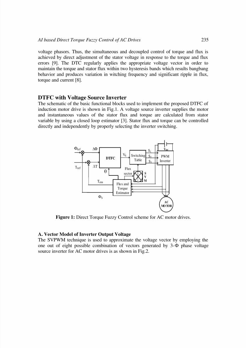
DTFC with Voltage Source InverterThe schematic of the basic functional blocks used to implement the proposed DTFC of
induction motor drive is shown in Fig.1. A voltage source inverter supplies the motor
and instantaneous values of the stator flux and torque are calculated from stator
variable by using a closed loop estimator [3]. Stator flux and torque can be controlleddirectly and independently by properly selecting the inverter switching.
VDC
Tref
Tem
Ф S
Ф ref
AC
MOTOR
S
V
M
DTFC Switching
TablePWM
Inverter
Flux andTorque
Estimator
∆ Ф
∆ T
θ
S1
S2
S3
VS
Flux
sector
Figure 1: Direct Torque Fuzzy Control scheme for AC motor drives.
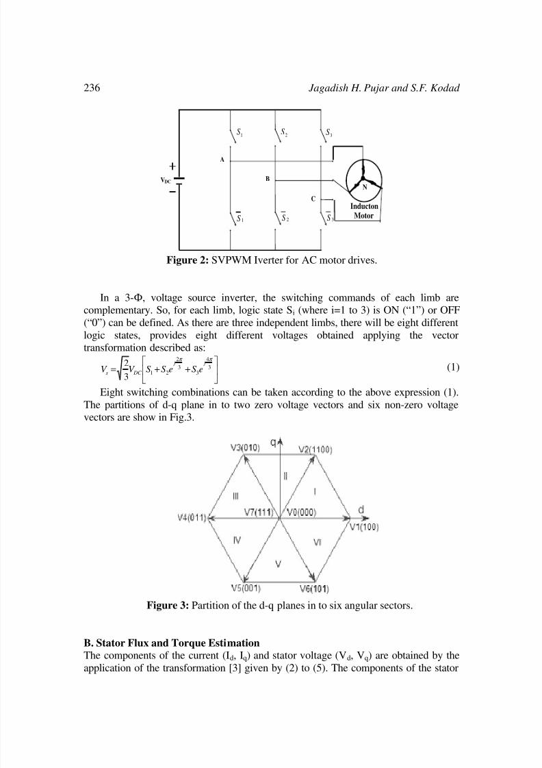
A. Vector Model of Inverter Output Voltage
The SVPWM technique is used to approximate the voltage vector by employing the
one out of eight possible combination of vectors generated by 3-Ф phase voltagesource inverter for AC motor drives is as shown in Fig.2.
8/10/2019 AI based Direct Torque Fuzzy Control of AC Drives.pdf
http://slidepdf.com/reader/full/ai-based-direct-torque-fuzzy-control-of-ac-drivespdf 4/12
236 Jagadish H. Pujar and S.F. Kodad
VDC
A
B
C
1S 2S 3S
1S 2S 3S
Inducton
Motor
N
Figure 2: SVPWM Iverter for AC motor drives.
In a 3-Ф, voltage source inverter, the switching commands of each limb are
complementary. So, for each limb, logic state Si (where i=1 to 3) is ON (“1”) or OFF
(“0”) can be defined. As there are three independent limbs, there will be eight different
logic states, provides eight different voltages obtained applying the vector
transformation described as:
⎥⎦
⎤⎢⎣
⎡++=
3
4
33
2
213
2 π π
j j
DC s eS eS S V V (1)
Eight switching combinations can be taken according to the above expression (1).
The partitions of d-q plane in to two zero voltage vectors and six non-zero voltagevectors are show in Fig.3.
Figure 3: Partition of the d-q planes in to six angular sectors.
B. Stator Flux and Torque Estimation
The components of the current (Id, Iq) and stator voltage (Vd, Vq) are obtained by the
application of the transformation [3] given by (2) to (5). The components of the stator

8/10/2019 AI based Direct Torque Fuzzy Control of AC Drives.pdf
http://slidepdf.com/reader/full/ai-based-direct-torque-fuzzy-control-of-ac-drivespdf 5/12
AI based Direct Torque Fuzzy Control of AC Drives 237
flux (ϕd, ϕq) given by (6) and (7) . The stator flux linkage per phase and the
electromagnetic torque estimated are given by (8) and (9) respectively. Ad I I
3
2=
(2)
( )C Bq I I I −=
2
1 (3)
( )⎟ ⎠
⎞⎜⎝
⎛ +−= 321
2
1
3
2S S S V V DC d
(4)
( )322
1S S V V DC q −= (5)
( )dt I RV
t
d S d d ∫ −=
0
φ (6)
( )dt I RV
t
qS qq ∫ −=
0
φ (7)
22
qd s φ φ φ += (8)
d qqd em I I pT φ φ −= (9)
The stator resistance RS can be assumed constant during a large number of
converter switching periods TS. The voltage vector applied to the induction motor
remains also constant over the time period TS. Therefore, resolving first equation of
system leads to:
( )dt I RV
t
S S S S ∫ −=
0
φ (10)
( ) ( ) S S S S T V t += 0φ φ (11)
In equation (11), φS(0) stands for the initial stator flux condition. This equation
shows that when the term RS I S can be neglected in high speed operating condition of
the extremity of stator flux vector VS. Also, the instantaneous flux speed is only
governed by voltage vector amplitude [3] given in (12).
S S V
dt
d ≈
φ (12)
Therefore, by selecting adequate voltage vector one can increase or decrease the
stator flux amplitude and phase to obtain the required performances. The deviation
obtained at the end of the switching period TS can be approached by the first order
Taylor Series. By choosing a suitable sequence of the vectors of tension, one can forcethe end of the vector flux to follow a desired trajectory. To function with a module of
practically constant fluxϕS, it is enough to choose an almost circular trajectory for the
end of the vector flux [3] [5].
C. Switching Table Formation
The vectors Vi+1 or Vi-1 are selected to increase the amplitude of flux, and Vi+2 or Vi-2 to
decrease it when flux is in sector I. Which shows that the choice of the vector tension
depends on the sign of the error of flux is independent of its amplitude [3]. Obviously,
the exit of the corrector of flux must be a Boolean variable. One adds a band of
hysteresis around zero to avoid unwanted commutations when the error of flux is very
8/10/2019 AI based Direct Torque Fuzzy Control of AC Drives.pdf
http://slidepdf.com/reader/full/ai-based-direct-torque-fuzzy-control-of-ac-drivespdf 6/12
238 Jagadish H. Pujar and S.F. Kodad
small [3] [4]. Indeed, with this type of corrector in spite of its simplicity, one can easily
control and maintain the end of the vector flux in a circular ring form. The switching
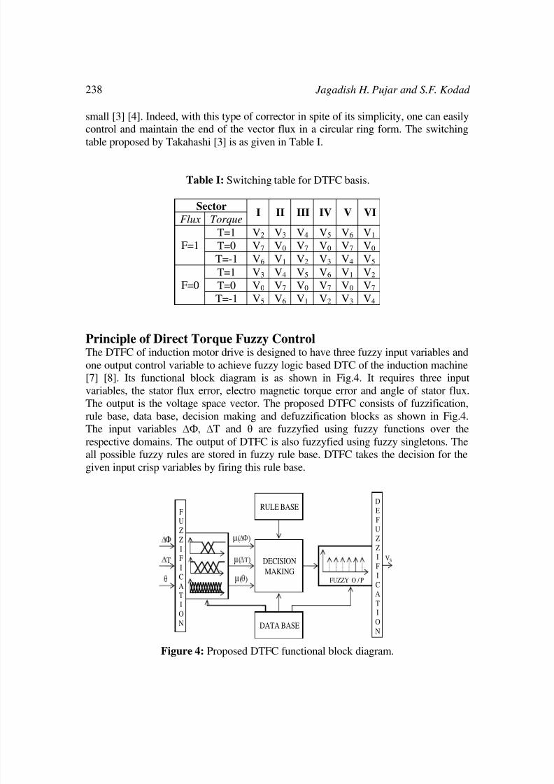
table proposed by Takahashi [3] is as given in Table I.
Table I: Switching table for DTFC basis.
Sector
Flux TorqueI II III IV V VI
T=1 V2 V3 V4 V5 V6 V1
T=0 V7 V0 V7 V0 V7 V0 F=1
T=-1 V6 V1 V2 V3 V4 V5
T=1 V3 V4 V5 V6 V1 V2 T=0 V0 V7 V0 V7 V0 V7 F=0
T=-1 V5 V6 V1 V2 V3 V4
Principle of Direct Torque Fuzzy ControlThe DTFC of induction motor drive is designed to have three fuzzy input variables and
one output control variable to achieve fuzzy logic based DTC of the induction machine
[7] [8]. Its functional block diagram is as shown in Fig.4. It requires three input
variables, the stator flux error, electro magnetic torque error and angle of stator flux.
The output is the voltage space vector. The proposed DTFC consists of fuzzification,
rule base, data base, decision making and defuzzification blocks as shown in Fig.4.The input variables ∆Ф, ∆T and θ are fuzzyfied using fuzzy functions over the
respective domains. The output of DTFC is also fuzzyfied using fuzzy singletons. The
all possible fuzzy rules are stored in fuzzy rule base. DTFC takes the decision for the
given input crisp variables by firing this rule base.
VS
θ
∆ T
∆ Ф
µ (∆ Ф )
µ (∆ T)
µ (θ )
F
U
Z
Z
IF
I
C
A
T
I
O
N
DECISION
MAKING
RULE BASE
DATA BASE
FUZZY O / P
D
E
F
U
Z
ZI
F
I
C
A
T
I
O
N
Figure 4: Proposed DTFC functional block diagram.

8/10/2019 AI based Direct Torque Fuzzy Control of AC Drives.pdf
http://slidepdf.com/reader/full/ai-based-direct-torque-fuzzy-control-of-ac-drivespdf 7/12
AI based Direct Torque Fuzzy Control of AC Drives 239
A. Flux Linkage Error Fuzzification
The flux linkage error is given by ∆Ф = Фref - ФS. Where Фref is the related value of
stator flux and ФS is actual stator flux. Three linguistic values, negative, zero and
positive denoted as N, Z and P respectively are used to fuzzify flux linkage error
domain [9] [10] as shown in Fig.5.
-0.05 0 0.05 ∆ Ф
PZNµ A
1
Figure 5: Flux linkage error domain fuzzification.
B. Electromagnetic Torque Error Fuzzification
The torque error given by ∆T = Tref - Tem. Where Tref is desired torque and Tem is actual
torque. Five linguistic values, negative large, negative small zero, positive small and
positive large denoted as NL,NS, ZE, PS and PL respectively are used to fuzzify
torque error domain [9] [10] as shown in Fig.6.
µ B
-0.025 -0.1 0 0.1 0.025 ∆ T
PLZENL1
NS PS
Figure 6: Electromagnetic torque error domain fuzzification.
C. Stator Flux Linkage Angle Fuzzification
The stator flux linkage angle θ is an angle between stator flux ϕS and a reference axis
is defined as ( )d q φ φ θ 1tan −
= . Twelve linguistic values, θ0 to θ12 are used to fuzzify the
domain of stator flux linkage angle [9] [10] as shown in Fig.7.

8/10/2019 AI based Direct Torque Fuzzy Control of AC Drives.pdf
http://slidepdf.com/reader/full/ai-based-direct-torque-fuzzy-control-of-ac-drivespdf 8/12
240 Jagadish H. Pujar and S.F. Kodad
θ
θ 0 θ 1 θ 2 θ 3 θ 4 θ 5 θ 6 θ 7 θ 8 θ 9 θ 1 0 θ 11 θ 12 µ C
1
12
23
12
21
12
19
12
17
12
15
12
13
12
11
12
9
12
7
12
5
12
3
120
π π π π π π π π π π π π
Figure 7: Stator flux linkage angle domain fuzzification.
D. Space Vector Voltage Fuzzification
The space vector voltage Vi ( i=1 to 6 ) is fuzzified using six singleton linguistic
values, as V1,V2,V3,V4,V5 and V6 [9] [10] as shown in Fig.8.
µ D
1
V1 V2 V3 V4 V5 V6 V
Figure 8: Space vector voltage domain fuzzification.
E. DTFC Rule Base Design
Each fuzzy rule can be described using the three input linguistic variables ∆ϕ, ∆T and
θ and one output linguistic variable VS in the DTFC rule base. The ith
IF-THEN fuzzy
rule Ri of DTFC can be expressed as:
Ri: IF ∆ϕ is Ai, ∆T is Bi and θ is Ci THEN VS is Di
Where Ai, Bi, Ci and Di are fuzzy membership function values obtained from µA,
µB, µC and µD membership functions of inputs and output linguistic variables of
DTFC respectively for ith
rule [9] [10].
In this paper, Mamdani’s fuzzy rule base model is developed to perform thefunction of proposed DTFC. Obviously the Mamdani’s implication is used to infer the
output of DTFC rule base for any crisp in put values of ∆ϕ, ∆T and θ. In the
defuzzification stage, a crisp value of the DTFC output is computed by using the center
of gravity method.
Simulation and the ResultsTo verify the proposed scheme, a numerical simulation has been carried out by using
MATLAB/SIMULINK. In the performed simulation, certain stator flux and torque
references are compared to the values calculated in flux and torque estimator and the

8/10/2019 AI based Direct Torque Fuzzy Control of AC Drives.pdf
http://slidepdf.com/reader/full/ai-based-direct-torque-fuzzy-control-of-ac-drivespdf 9/12
AI based Direct Torque Fuzzy Control of AC Drives 241
corresponding errors are sending to the Direct Torque Fuzzy Controller of the
induction motor drive system. The outputs of the flux and torque comparators along
with stator flux linkage angle are used in order to determine the appropriate voltage
vector and stator flux space vector. Vector locations are shown in order to validate the
control strategies as discussed above. A digital simulation studies were made by using
the S-factions and SIMULINK software of MATLAB environment for the system
described in Fig.1. The flux and torque loops of the drive were also designed and
simulated respectively using fuzzy logic control techniques. The feedback control
algorithms were iterated until best simulation results were obtained. The proposed
DTFC is simulink model is developed by using Fuzzy Toolbox.
For the simulation, a four pole, 3 KW, 1500 rpm, three phase, 220/440 volts and 50
Hz induction motor AC drive system is developed using S-functions, Fuzzy Toolbox
and SIMULINK of the MATLAB. The rated parameters of induction motor areRs=4.85Ω, Rr=3.805Ω, Ls=0.275H, Lr=0.274H, Msr=0.258H, J=0.031kgm2 and
B=0.00039. The inverter dc bus voltage is 160 volts. The proposed DTFC AC drive
system dynamic responses were obtained by simulation of the proposed AC drive
system of Fig.1 at a sampling time period of 1000 µs. The pulsating ripple in the actual
torque simulated response of DTFC shown in Fig.11 is very much reduced compare to
the actual torque simulated response of conventional DTC shown in Fig.10 for the
same corresponding estimated torque simulated response shown in Fig.9.
The Direct Torque Fuzzy Control of induction motor presents the advanced
performance to achieve tracking of the desired smooth circular trajectory of stator flux
locus shown in Fig.13. The DTFC speed response shown in Fig.12 rejects the load
disturbance rapidly with no overshoot and with a negligible steady state errorcompared to the conventional DTC. The reason for superior performance of DTFC of
AC drive system is basically adaptive in nature and is able to realize and fire
corresponding stable control fuzzy rules for each input state of inputs ∆ϕ, ∆T and θ.
Figure 9: Estimated torque simulated response.

8/10/2019 AI based Direct Torque Fuzzy Control of AC Drives.pdf
http://slidepdf.com/reader/full/ai-based-direct-torque-fuzzy-control-of-ac-drivespdf 10/12
242 Jagadish H. Pujar and S.F. Kodad
Figure 10: Conventional DTC torque simulated response.
Figure 11: DTFC torque simulated response.
Figure 12: DTC and DTFC actual speed simulated responses.

8/10/2019 AI based Direct Torque Fuzzy Control of AC Drives.pdf
http://slidepdf.com/reader/full/ai-based-direct-torque-fuzzy-control-of-ac-drivespdf 11/12
AI based Direct Torque Fuzzy Control of AC Drives 243
Figure 13: DTFC stator flux locus simulated response.
ConclusionsThe paper presents a new approach for speed control of 3-Ф induction motor using
fuzzy logic technique. The paper develops a fuzzy logic based DTC methodology for
AC drive systems is intended for an efficient control of the torque and flux without
changing the motor parameters. Also the flux and torque can be directly controlled
with the inverter voltage vector using SVPWM methodology.
A complete direct torque fuzzy control of SVPWM voltage source inverter-fed
induction motor drive system has been described. The system was analyzed, designed
and performances were studied extensively by simulation to validate the theoretical
concept. The simulation results shows that the proposed DTFC method is superior toconventional DTC in robustness and in tracking precision. It appears from the response
properties that it has a high performance in presence of load disturbances.
The control of speed by DTFC gives fast dynamic response with no overshoot and
negligible steady state error. So, it is concluded that DTFC can be applied for AC
drives and is reliable in a wide speed range. Especially in AC servo motor applications,
where high dynamic performance is demanded. DTFC has a great advantage over
other control methods due to its property of fast torque response. In order to increase
the performance, control period should be selected as short as possible. When the
sampling interval is selected smaller, it is possible to keep the bandwidth smaller and
to control the stator magnetic flux more accurately.
The simulation study clearly indicates the superior performance of DTFC overconventional DTC, because it is inherently adaptive in nature. To make this DTFC AC
drive system fully adaptive, the hybridization of fuzzy with other soft computing
techniques like ANN and Rough Sets will be preferred.
References
[1] Mamdani, E. H. “Applications of Fuzzy Algorithms for Simple Dynamic
Plants”, Proc. of the IEE 121, pp. 1585 – 1588, 1974.
8/10/2019 AI based Direct Torque Fuzzy Control of AC Drives.pdf
http://slidepdf.com/reader/full/ai-based-direct-torque-fuzzy-control-of-ac-drivespdf 12/12
244 Jagadish H. Pujar and S.F. Kodad
[2] F. Blaschke “The principle of field orientation as applied to the new
TRANSVECTOR closed loop control system for rotating field machines”,
Siemens Review XXXIX, 1972, (5): 217–220.
[3] Takahashi I, Naguchi T. “A new quick-response and high-efficiency control
strategy of an induction motor”. IEEE Transactions on Industry Application
[ISSN 0093-9994], 1986, IA-22(5): 820-827.
[4] P. Tiitinen, M. Surandra, “The next generation motor control method, dtc
direct torque control”, Proc on Power Electronics, 1996, 1: 37–43. Drives
and Energy Systems for industrial growth.
[5] D. Casadei, G. Grandi, G. Serra, A. Tani ”Effectes of flux and torque
hysteresis band amplitude in direct torque control of induction machines”,
IEEE-IECON-94, 1994, 299–304.
[6]
Hui-Hui Xiao, Shan Li, Pei-Lin Wan, Ming-Fu Zhao, ″Study on Fuzzy DirectTorque Control System″, Proceedings of the Fourth International Conference
on Machine Learning and Cybernetics, Beijing, 4-5 August 2002.
[7] R.Toufouti S.Meziane, H. Benalla, “Direct Torque Control for Induction
Motor Using Fuzzy Logic”, Proc. ACSE Journal, Vol. 6, Issue 2, pp. 19 – 26,
Jun. 2006.
[8] S. Benaicha, R. Nait-Said, F. Zidani, M-S. Nait-Said, B. Abdelhadi, “A direct
torque fuzzy control of SVM inverter-fed Induction Motor drive”, Proc. of the
International Journal of Artificial Intelligence and Soft Computing Vol. 1,
Nos. 2-4, pp. 259 – 270, 2009.
[9] Hui-Hui Xia0, Shan Li, Pei-Lin Wan, Ming-Fu Zhao, ″Study on Fuzzy Direct
Torque Control System″, Proceedings of the Fourth International Conferenceon Machine Learning and Cybernetics, Beijing, pp. 4-5 August 2002.
[10] Yang Xia and Oghanna, W ″Study on fuzzy control of induction machine with
direct torque control approach,″ Industrial Electronics, 1997. ISIE apos; 97,
Proceedings of the IEEE International Symposium on Volume 2, Issue, pp:
625 – 630, 7-11 Jul 1997.


![Fuzzy Logic Direct Torque Control for Asynchronous Motor...Fuzzy logic has been proved to be powerful in the motor control area, e.g., in the PI and [6] Fuzzy Logic Controllers (FLC)](https://static.fdocuments.us/doc/165x107/5f6eca7f1a2ba4328d743464/fuzzy-logic-direct-torque-control-for-asynchronous-motor-fuzzy-logic-has-been.jpg)