Ahmed Abdel-Fattah Jerry Chang (a.k.a. Fred) Derrick Culver Matt Zenthoefer.
19
Ahmed Abdel-Fattah Ahmed Abdel-Fattah Jerry Chang (a.k.a. Fred) Jerry Chang (a.k.a. Fred) Derrick Culver Derrick Culver Matt Zenthoefer Matt Zenthoefer
-
date post
20-Dec-2015 -
Category
Documents
-
view
219 -
download
0
Transcript of Ahmed Abdel-Fattah Jerry Chang (a.k.a. Fred) Derrick Culver Matt Zenthoefer.

Ahmed Abdel-FattahAhmed Abdel-Fattah
Jerry Chang (a.k.a. Fred)Jerry Chang (a.k.a. Fred)
Derrick CulverDerrick Culver
Matt ZenthoeferMatt Zenthoefer
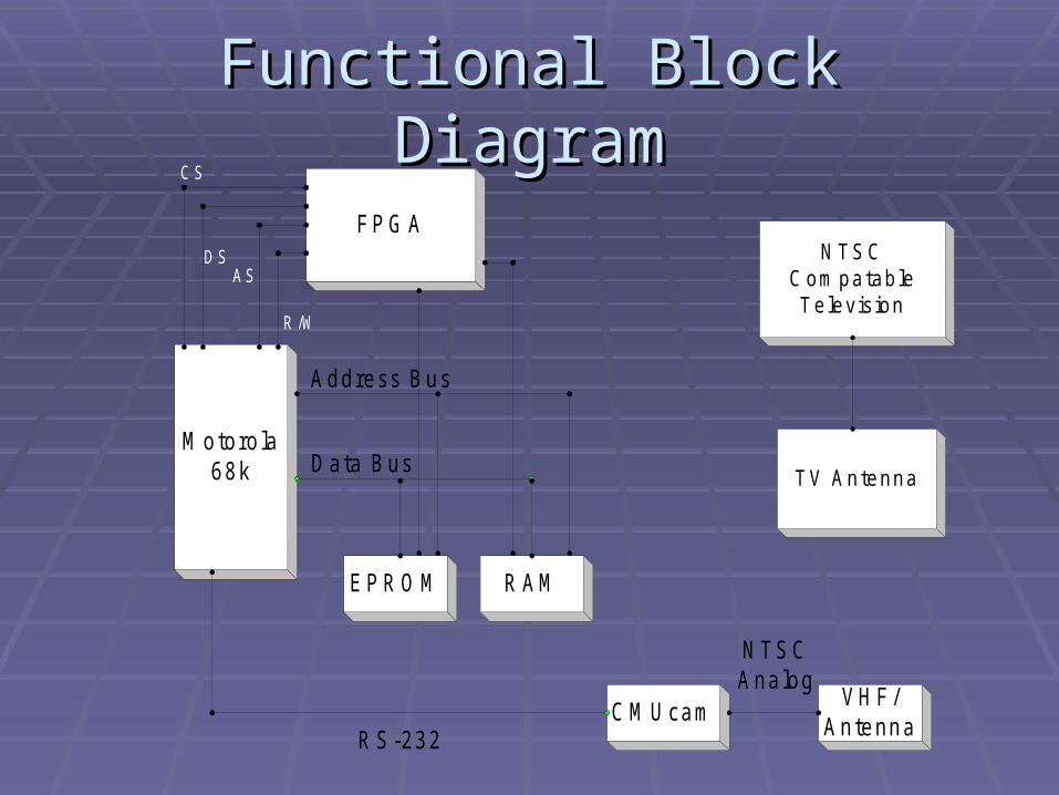
Functional Block DiagramFunctional Block Diagram
N TSC
C om patableTelevis ion
TV Antenna
M otoro la68k
FPG A
R AMEPR O M
VH F/Antenna
C M U cam
D ata Bus
Address Bus
R /W
ASD S
C S
R S-232
N TSCAnalog

Camera: CMUcam2Camera: CMUcam2

Camera FeaturesCamera Features
Track Track useruser defined color blobs defined color blobs Colors must be bright and distinctColors must be bright and distinct
Track motion using frame Track motion using frame differencingdifferencing
Find the centroid of any tracking Find the centroid of any tracking datadata
Black and white NTSC analog outputBlack and white NTSC analog output

Communication protocol was Communication protocol was designed to accommodate slow designed to accommodate slow processorsprocessors
Up to 176 x 255 Resolution Up to 176 x 255 Resolution NTSC requires OV7620 camera NTSC requires OV7620 camera
modulemodule Input power goes through a 5V Input power goes through a 5V
regulatorregulator
More FeaturesMore Features

Testing the CameraTesting the Camera
Use PC to grab a frame from the cameraUse PC to grab a frame from the camera Focus the lensFocus the lens Demo ModeDemo Mode
The camera tracks an object using two servos The camera tracks an object using two servos to adjust the pan and tilt of the the camerato adjust the pan and tilt of the the camera

RS-232 ProtocolRS-232 Protocol
Interface to CPU through Interface to CPU through UART(16550)UART(16550) Provide buffering (through FIFOs)Provide buffering (through FIFOs) Interrupt outputs (no need of polling)Interrupt outputs (no need of polling) Read and write bytesRead and write bytes Handles stop, start, and parity bitsHandles stop, start, and parity bits

Parts NeededParts Needed
MAX232 chip (puts out RS232 MAX232 chip (puts out RS232 voltages)voltages)
UART chipUART chip
Clock (1.8432 MHz)Clock (1.8432 MHz)

SchematicSchematic

Power SupplyPower Supply A power supply will be constructed in order to
convert an input of 120VAC to outputs of 9VDC and 5VDC
6:1 Transformer will be used to convert 120VAC to 20VAC
Full-Wave Rectifier Bridge will then be used to rectify the AC voltage
LM7809 Regulator 9VDC
LM7805 Regulator 5VDC

Power Supply DesignPower Supply Design

Reset ButtonReset Button
First component completed Reset Button
The reset button was tested to check it functionality using a logic analyzer Made sure RES went low-true

Microprocessor TestingMicroprocessor Testing
Test processor’s read abilityTest processor’s read ability After the reset button is pushedAfter the reset button is pushed Processor reads in first eight bytes from reset Processor reads in first eight bytes from reset
vectorvector Using a logic analyzer we will read the address Using a logic analyzer we will read the address
on the address line and “FFFF” on the data lineon the address line and “FFFF” on the data line
Future TestingFuture Testing Use DIP switch for processor to read logic valuesUse DIP switch for processor to read logic values Use LEDs to display data that the processor Use LEDs to display data that the processor
writeswrites

VHF Transmitter and RF VHF Transmitter and RF AmpAmp
Will be fed using the CMUcam2’s NTSC Will be fed using the CMUcam2’s NTSC analog outputanalog output
The analog NTSC signal will be AM The analog NTSC signal will be AM modulated at the VHF picture carrier modulated at the VHF picture carrier frequency of 175.25MHzfrequency of 175.25MHz
Design of the TV transmitter will use a Design of the TV transmitter will use a transistor and tank circuittransistor and tank circuit
The modulated output will go to a The modulated output will go to a wideband op-amp wideband op-amp At least a 6MHz bandwidth to insure total At least a 6MHz bandwidth to insure total
transmission of NTSC signaltransmission of NTSC signal
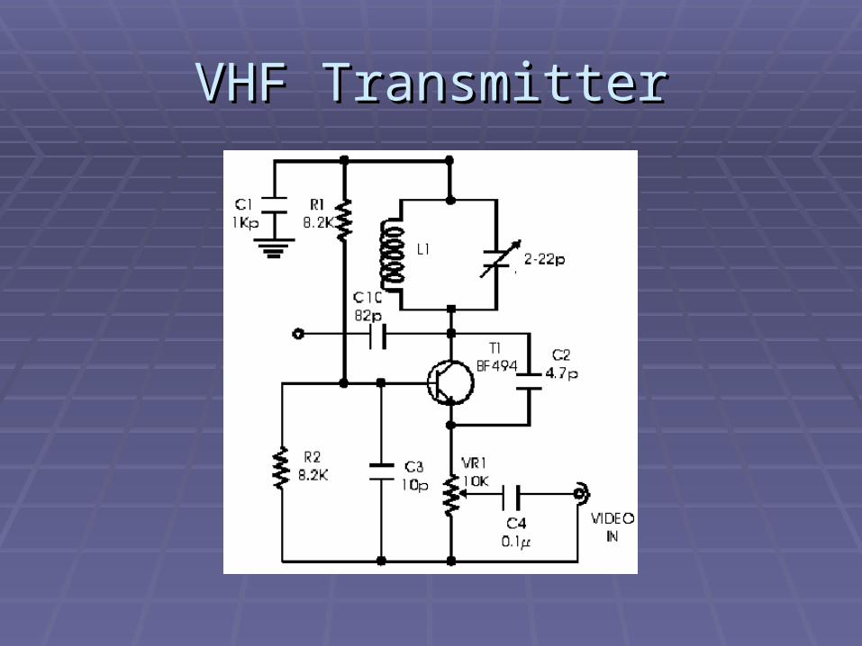
VHF TransmitterVHF Transmitter

AntennaAntenna
Yagi-Uda AntennaYagi-Uda Antenna = 1.71m= 1.71m Has reflector and Has reflector and
director elements director elements to increase gain to increase gain and directivityand directivity
A transmission A transmission range of 5-10 range of 5-10 meters is feasiblemeters is feasible

Impedance MatchingImpedance Matching
VHF transmitter output impedance VHF transmitter output impedance will be matched to the input will be matched to the input impedance of the antennaimpedance of the antenna
Several matching options:Several matching options: Quarter wave transformerQuarter wave transformer Stub matchingStub matching Component matchingComponent matching
Most likely will use component matching Most likely will use component matching because carrier frequency is low enoughbecause carrier frequency is low enough

ScheduleSchedule

Questions?Questions?