Agrocompact f60 f70 f80 f90 Repair manual
520
introduction This publication is intended for the trained technician who must operate on our tractors. It contains all general inf ormati on relati ng to our tractor range, and in par ticular it highli ghts the ins pection, overhauli ng and adjustment procedures as well as the main instructions for dismantling and reassembling operations. The wor kshop manual is a nat ural summary for the mechanic who has att ended the vocati onal traini ng and specializa - ti on cour ses, which are held ever y year at our Service School , to permit hi m to perform a precise and qual ified work on tractor. Its contents are therefore an exhaustive reference book for the experienced mechanic who desires to refresh his me - mory on the sequence of the operations to be done. It is then good practice for every authorized dealer mechanic to have at his disposal this publication, so that it may be consulted quickly when necessary. We wi sh to thank in advance for the cooper at ion al l thos people, who wi ll let us have thei r suggesti ons in or der to make this publication more complete. 1 WORKSHOP MANUAL
-
Upload
zik-servis -
Category
Documents
-
view
479 -
download
29
Transcript of Agrocompact f60 f70 f80 f90 Repair manual

8/19/2019 Agrocompact f60 f70 f80 f90 Repair manual
http://slidepdf.com/reader/full/agrocompact-f60-f70-f80-f90-repair-manual 1/519
introduction
This publication is intended for the trained technician who must operate on our tractors.
It contains all general information relating to our tractor range, and in particular it highlights the inspection, overhaulingand adjustment procedures as well as the main instructions for dismantling and reassembling operations.
The workshop manual is a natural summary for the mechanic who has attended the vocational training and specializa -tion courses, which are held every year at our Service School, to permit him to perform a precise and qualified work ontractor.
Its contents are therefore an exhaustive reference book for the experienced mechanic who desires to refresh his me -mory on the sequence of the operations to be done. It is then good practice for every authorized dealer mechanic tohave at his disposal this publication, so that it may be consulted quickly when necessary.
We wish to thank in advance for the cooperation all thos people, who will let us have their suggestions in order to makethis publication more complete.
1
WORKSHOP MANUAL

8/19/2019 Agrocompact f60 f70 f80 f90 Repair manual
http://slidepdf.com/reader/full/agrocompact-f60-f70-f80-f90-repair-manual 2/519
LIST OF CONTENTS
Tractor configurations AGROCOMPACT .................................................................................................................6Dimensions and weights...........................................................................................................................................7Prescribed lubricants and capacities ......................................................................................................................10Conversion tables...................................................................................................................................................11Parts .......................................................................................................................................................................12
1 - ENGINEEngine section ........................................................................................................................................................13General characteristics...........................................................................................................................................20Timing specifications ..............................................................................................................................................21Lubrication system - specifications.........................................................................................................................22Fuel supply system - specifications ........................................................................................................................23Turbocharger - specifications .................................................................................................................................24Cooling system .......................................................................................................................................................25Engine cylinder block..............................................................................................................................................26Installing bushings into the camshaft journals ........................................................................................................26 Adjusting backlash between the gear teeth of the auxiliary engine drive ...............................................................27Support for hydraulic pumps or air compressor located between engine block and timing cover ..........................27Timing idler gea ......................................................................................................................................................29Cylinders.................................................................................................................................................................30Main bearings .........................................................................................................................................................33Crankshaft ..............................................................................................................................................................35Connecting rods - connecting rod bearings and bushings .....................................................................................38Pistons ....................................................................................................................................................................39Piston rings.............................................................................................................................................................39Counterweights for 4-cylinder engines ...................................................................................................................44Engine flywheel ......................................................................................................................................................45Checking camshaft .................................................................................................................................................48Checking camshaft bushings..................................................................................................................................48Checking timing gear ..............................................................................................................................................48Cylinder heads - valves - valve rockers ..................................................................................................................49Cleaning cylinder heads .........................................................................................................................................50Checking engine compression ...............................................................................................................................53Oil pump ................................................................................................................................................................54Checking pressure relief valve ...............................................................................................................................54Fitting shims between engine oil pan and front support .........................................................................................55Fuel injection nozzles .............................................................................................................................................56Mechanical-type engine governor ......................................................................................................................58Mounting governor weights ...................................................................................................................................59Calibrating engine governor ...................................................................................................................................61Engine governor control assembly .........................................................................................................................64Installing and checking the pick-up.........................................................................................................................68Installing and checking actuator .............................................................................................................................69Fuel injection pumps...............................................................................................................................................76Injection pump control system ................................................................................................................................76Installing injection pump control bar guide supports ..............................................................................................77Engine timing ..........................................................................................................................................................77Positioning the pumps ............................................................................................................................................80Fuel prefilter............................................................................................................................................................83Fuel filter.................................................................................................................................................................83Draining water from fuel filter..................................................................................................................................83Fan assembly .........................................................................................................................................................85Turbocharging 70F3 - F90 ....................................................................................................................................88Engine air filter........................................................................................................................................................92
Tightening torques ..................................................................................................................................................92Instructions for engine assembly ............................................................................................................................94Diagnosing malfunctions ......................................................................................................................................108
2
8/19/2019 Agrocompact f60 f70 f80 f90 Repair manual
http://slidepdf.com/reader/full/agrocompact-f60-f70-f80-f90-repair-manual 3/519
2 - CLUTCHGearshift clutch.....................................................................................................................................................110Spring specifications to Belleville washer for the clutch engagement ..................................................................110Cecking clutch ......................................................................................................................................................114 Adjusting clutch control pedal ...............................................................................................................................114Bleeding air from the hydraulic circuit...................................................................................................................114Stripping the slave cylinder...................................................................................................................................115Stripping the master cylinder................................................................................................................................116Diagnosing malfunctions ......................................................................................................................................118Powershift unit......................................................................................................................................................119Powershift unit detach from the gear box .............................................................................................................122 Assembly of Powershift unit .................................................................................................................................133Re-assembly of the Powershift unit. .....................................................................................................................135Fitting the oil manifolds of the Powershift unit ......................................................................................................138Diagnosing malfunctions ......................................................................................................................................142
3 - TRANSMISSIONGeneral specifications ..........................................................................................................................................143Technical specifications........................................................................................................................................143Speed change configurations ...............................................................................................................................144Longitudinal section through transmission ...........................................................................................................149Longitudinal section through transmission with Powershift unit ...........................................................................150Rear axle longitudinal section...............................................................................................................................151Views of the gearbox. ...........................................................................................................................................154Views of the gearbox with hydraulic shuttle..........................................................................................................156Range selector rods and forks..............................................................................................................................159Hydraulic shuttle control .......................................................................................................................................160Removal and refitting............................................................................................................................................161Removal of the rear gearbox without removing the platform (tractors equipped with platform or cab only).........161Separating the front gearbox from the engine......................................................................................................162Dismantling the gearbox.......................................................................................................................................162
Removal of the gearbox input and P.T.O. shafts..................................................................................................162Separating the Powershift unit from the gearbox ................................................................................................162Removal of the gear train positioned in the front gearbox....................................................................................163Disassembly of the inversor control rods and forks..............................................................................................164Dismantling of the gearchange rod and fork assembly. .......................................................................................165Dismantling of the gearchange selector rods and forks assembly .......................................................................166Removal of the shaft with the actuator for engagement/disengagement of the front-wheel drive........................167Removal of the range gear shaft ......................................................................................................................... 167Examining parts removed.....................................................................................................................................168Gearbox case .......................................................................................................................................................168Shafts ...................................................................................................................................................................168Gears....................................................................................................................................................................168Synchronizers.......................................................................................................................................................168Bearings ...............................................................................................................................................................168 Adjusting play of the gearbox shafts by means of the thrust plates on themini/inversor shaft and the secondary shaft........................................................................................................169
Warnigns related to assembly of the gears of the P.T.O. unit, the range reduction unitand synchronised P.T.O. shaft ............................................................................................................................173
Assembly of the P.T.O.........................................................................................................................................173Installation of the range reduction unit, the gear for the front-wheel drive shaft and the parking brake discs......173Points where sealant is to be used.......................................................................................................................177Bevel drive adjustment .........................................................................................................................................183Servicing operations .............................................................................................................................................184Tightening torques................................................................................................................................................184Rear power take-off..............................................................................................................................................185P.T.O. clutch.........................................................................................................................................................192Technical specifications........................................................................................................................................193Correct positions of P.T.O. sensors and cables ...................................................................................................193Clutch inspection ..................................................................................................................................................195Checking clutch hydraulic pressures....................................................................................................................196Checking the end-play of the front shaft of the P.T.O. clutch...............................................................................197Renewal of the rear P.T.O. clutch ........................................................................................................................198Main operations for removal of the rear P.T.O. unit .............................................................................................199Ooperations for removal of the rear P.T.O. unit ...................................................................................................200Diagnosing malfunctions ......................................................................................................................................204
3

8/19/2019 Agrocompact f60 f70 f80 f90 Repair manual
http://slidepdf.com/reader/full/agrocompact-f60-f70-f80-f90-repair-manual 4/519
4 - AXLESRear axle ..............................................................................................................................................................205Installing the rear half-shafts ...............................................................................................................................205Removal and disassembly of the epicyclic reduction unit.........................................................................................208Fitting lateral stub axles of the wheel ...................................................................................................................2092WD extendible axle.............................................................................................................................................210Removing the axle from the front support ............................................................................................................212Wheel hub ............................................................................................................................................................214Front-wheel drive ..................................................................................................................................................217Removal of the axle from the front carrier ............................................................................................................218Epicyclic reduction unit .........................................................................................................................................221Side hubs..............................................................................................................................................................223Fitting the front axle studs ....................................................................................................................................224 Axle shafts ............................................................................................................................................................224Gears....................................................................................................................................................................224Bearings ...............................................................................................................................................................224 Adjusting bevel gears ...........................................................................................................................................226 Adjustment of the internal control of the mechanical differential lock ..................................................................227Installing the differential assembly into the drive axle ..........................................................................................227Fitting the steering angle limiting bolts .................................................................................................................228Diagnosing malfunctions ......................................................................................................................................230
5 - VEHICLEBrakes ..................................................................................................................................................................231Hydraulic pump.....................................................................................................................................................232 Assembly of brake master cylinder.......................................................................................................................234Checking the front brake disks on 2WD and 4WD front axles and the rear brake disks. .....................................235 Adjusting service brake pedals .............................................................................................................................235Correct installation of inspection cover for parking brake discs............................................................................236Checking parking brake pads ...............................................................................................................................236
Bleeding air from the brake hydraulic system.......................................................................................................237Valve “Separate Brakes” ......................................................................................................................................238Diagnosing malfunctions ......................................................................................................................................242Hydraulic lift with load sensing .............................................................................................................................243Installing the lift and front cover plate of the gearbox...........................................................................................244Lift mechanism .....................................................................................................................................................244Checking the safety valves...................................................................................................................................244Hydraulic valve .....................................................................................................................................................245 Adjusting the lift ....................................................................................................................................................247Sensing arm assembly .........................................................................................................................................256Power-lift distributor valve spring setting specifications .......................................................................................257Electronic lift .........................................................................................................................................................258Control level or depth control knob.......................................................................................................................259Mix position/draft control.......................................................................................................................................259Lowering speed control knob................................................................................................................................260Maximum lift height control knob ..........................................................................................................................260Up/Down control switch ........................................................................................................................................260Up control .............................................................................................................................................................260Control/Float mode ...............................................................................................................................................260Lift status indicator light ........................................................................................................................................260Remote pushbuttons for lift operation from ground ..............................................................................................261Calibration of the AUTOMATIC ............................................................................................................................263Emergency manual lift control ...............................................................................................................................263Hydraulic control valve of the electronic lift ..........................................................................................................264Precautions for electronic equipment ...................................................................................................................275Checking the electronics system ..........................................................................................................................275Checking mechanical components.......................................................................................................................275Front hydraulic lift .................................................................................................................................................276Hydraulic accumulator and antishock valve for front lift .......................................................................................277Front power take-off .............................................................................................................................................279Checking the clutch ..............................................................................................................................................280Testing the pressure settings of the clutch control valve .....................................................................................280Instructions for disengaging the drive to the front P.T.O. .....................................................................................283Fitting the "RING-FEEDER" rings ........................................................................................................................284Diagnosing malfuntions ........................................................................................................................................288
4
8/19/2019 Agrocompact f60 f70 f80 f90 Repair manual
http://slidepdf.com/reader/full/agrocompact-f60-f70-f80-f90-repair-manual 5/519
6 - CONTROLSHydrostatic steering..............................................................................................................................................289Inspections and checks ........................................................................................................................................290Steering pump ......................................................................................................................................................290Directional control valve ......................................................................................................................................290Check the setting of the pressure relief valve.......................................................................................................290Bleeding the hydraulic circuit................................................................................................................................290 Assembly of orbital pump unit ..............................................................................................................................290Teering wheel shaft .............................................................................................................................................291Steering cylinders .................................................................................................................................................291Instructions for the hydrostatic steering distributor assembly...............................................................................293Diagnosing malfuntions ........................................................................................................................................299Mechanical controls..............................................................................................................................................300Electro-hydraulic controls .....................................................................................................................................316Front P.T.O. clutch engagement control...............................................................................................................316Rear P.T.O. clutch engagement control ...............................................................................................................316Differential lock engagement control ....................................................................................................................316Front-wheel drive engagement control .................................................................................................................316Rear P.T.O. engagement control..........................................................................................................................316Gearbox................................................................................................................................................................316Front and rear lift ..................................................................................................................................................316Electro-hydraulic controls for adjustment of the right-hand lift rod and the lateral stabilisers...............................316Piston for hydraulic adjustment of stabilisers .......................................................................................................331 Adjustment of front and rear differential lock control ...........................................................................................332
7 - BODYWORKPlatform ................................................................................................................................................................333
Cab air filter ..........................................................................................................................................................337Screen wash.........................................................................................................................................................337Screen wipers (front and rear)..............................................................................................................................337Remove cab. ........................................................................................................................................................338Breakage of the top hood release cable...............................................................................................................338
8 - SYSTEMS
Ventilation.............................................................................................................................................................339Heating System....................................................................................................................................................339Operation and maintenance of the air-conditioning system .................................................................................344Water dripping from the points at which condensate drain lines are connected to the conditioning unit .............345Checking system..................................................................................................................................................347System safety elements .......................................................................................................................................347Temperature regulation ........................................................................................................................................347Charging the system.............................................................................................................................................348Filling the metering unit ........................................................................................................................................348Refilling the system with oil ..................................................................................................................................348Verifying operation of the system after recharging ...............................................................................................350Directions for tightening air conditioning system pipeline fittings. ........................................................................350Diagnosing malfuntions ........................................................................................................................................353Hydraulic system..................................................................................................................................................354Oil filters................................................................................................................................................................356
Hydraulic pumps...................................................................................................................................................356Checking the relief valves of the hydraulic lift system.......................................................................................... 356Stripping the hydraulic pump................................................................................................................................357
5

8/19/2019 Agrocompact f60 f70 f80 f90 Repair manual
http://slidepdf.com/reader/full/agrocompact-f60-f70-f80-f90-repair-manual 6/519
Auxiliary hydraulic spool valves ............................................................................................................................359Conversion of auxiliary spool valves from double acting to single acting operation (see fig 5) ............................362Trailer hydraulic braking system...........................................................................................................................367Trailer hydraulic braking distributor unit................................................................................................................367Use of the tractor with CUNA 341/01 hydraulic trailer braking .............................................................................369Starting .................................................................................................................................................................370Installing the hydraulic braking valve for trailers equipped with “safety brake” ..........................................................374Electrical system...................................................................................................................................................377General safety directions ......................................................................................................................................378Jump start utilizing another battery.......................................................................................................................379
Recharge system..................................................................................................................................................381Heating system.....................................................................................................................................................381Heating system.....................................................................................................................................................382Heating and conditioning system..........................................................................................................................382Starting system.....................................................................................................................................................382Ignition key ...........................................................................................................................................................384Ventilation control .................................................................................................................................................384Push button control...............................................................................................................................................384Wiper switch .........................................................................................................................................................385Screen washer switch...........................................................................................................................................386Work ligths ............................................................................................................................................................386Beacon push button..............................................................................................................................................386Relay ....................................................................................................................................................................387Electronic flasher unit ...........................................................................................................................................387Switch controlling .................................................................................................................................................388Switch controlling: differential lock - P.T.O. clutch - 4WD - 540 1000 rpm/min P.T.O. - speed selector - Economy P.T.O. - Live P.T.O. - electric starter system.....................................................................................388
Switch for emergency brake .................................................................................................................................388Fuse box...............................................................................................................................................................389Instrument panel with digital display.....................................................................................................................390Engine stop operation with a type 2MH engine control unit .................................................................................392Electrical wiring.....................................................................................................................................................394
9 - APPENDIXEngine electronic unit ................................................................................................................................................IPower lift tester version ....................................................................................................................................XLVII
6

8/19/2019 Agrocompact f60 f70 f80 f90 Repair manual
http://slidepdf.com/reader/full/agrocompact-f60-f70-f80-f90-repair-manual 7/519
TRACTOR CONFIGURATIONS:
AGROCOMPACT F60 - 70F3 - 70F4 - F80 - F90
F60 - 70F3 - 70F4 - F80 - F90 2RM WITH PLATFORMA2RM WITH CAB4RM WITH PLATFORMA4RM WITH CAB
CAB - ventilation + heating- with ventilation + heating + air conditioning
GEARBOX Fully synchronised:
For tractors with driving position with footsteps only- 16 Forward + 8 Reverse: 4 speeds x 2 ranges + mini-reduction + shuttle- 24 Forward + 12 Reverse: 4 speeds x 3 ranges + mini-reduction + shuttle
For tractors with driving position with plataform/cab only- 20 Forward 10 Reverse: 5 speeds x 2 ranges (L-V) + mini-reduction-shuttle- 30 Forward 15 Reverse: 5 speeds x 3 ranges (SR-L-V) + mini-reduction-shuttle
- 45 Forward 45 Reverse: 5 speeds x 3 ranges (L-N-V)+ Reverser + version Powershift - -
CONTROLS - electro-hydraulic POWERSHIFT control with 2 pushbuttons located on gear lever- rear P.T.O. clutch with electro-hydraulic control and mechanical speed selector- groundspeed P.T.O. with mechanical engagement/disengagement control- front P.T.O. with electrohydraulic control- 4WD with mechanical control or optional electro-hydraulic control- differential locks with electro-hydraulic control for tractors equipped with platform or cab- differential locks with mechanical control for tractors with footplates- with electronic engine throttle (for tractors equipped with electronic governor)
MECHANICALLY OPERATED REAR POWER-LIFT - with supplementary rams- without supplementary rams
ELECTRONIC REAR LIFT - with auxiliary rams- without auxiliary rams- with auxiliary control pushbuttons mounted on fender
HYDRAULIC SYSTEM The hydraulic system is equipped with two pumps:Standard:- 11 cc pump with 27 l/min capacity. Supplies power steering, electro-hydraulic control unit and gearbox
lubrication circuits.- 14 cc pump with 34 l/min capacity. Supplies auxiliary service control valves and hydraulic lift.Optional:- 11 cc pump with 27 l/min capacity. Supplies power steering, POWERSHIFT control unit, electro-hydraulic
control unit and gearbox lubrication circuits.- 19 cc pump with 47 l/min capacity. Supplies the hydraulic trailer breaking control valve, auxiliary service
control valves and hydraulic lift.
MAIN EQUIPMENT - front P.T.O.- Economy P.T.O.- front lift- Electronic lift- Electronic engine governor- 3-point linkage with hydraulically adjustable right-hand lift rod and stabilisers- 4-way or 6-way control valves with “Flow Divider”
7
8/19/2019 Agrocompact f60 f70 f80 f90 Repair manual
http://slidepdf.com/reader/full/agrocompact-f60-f70-f80-f90-repair-manual 8/519
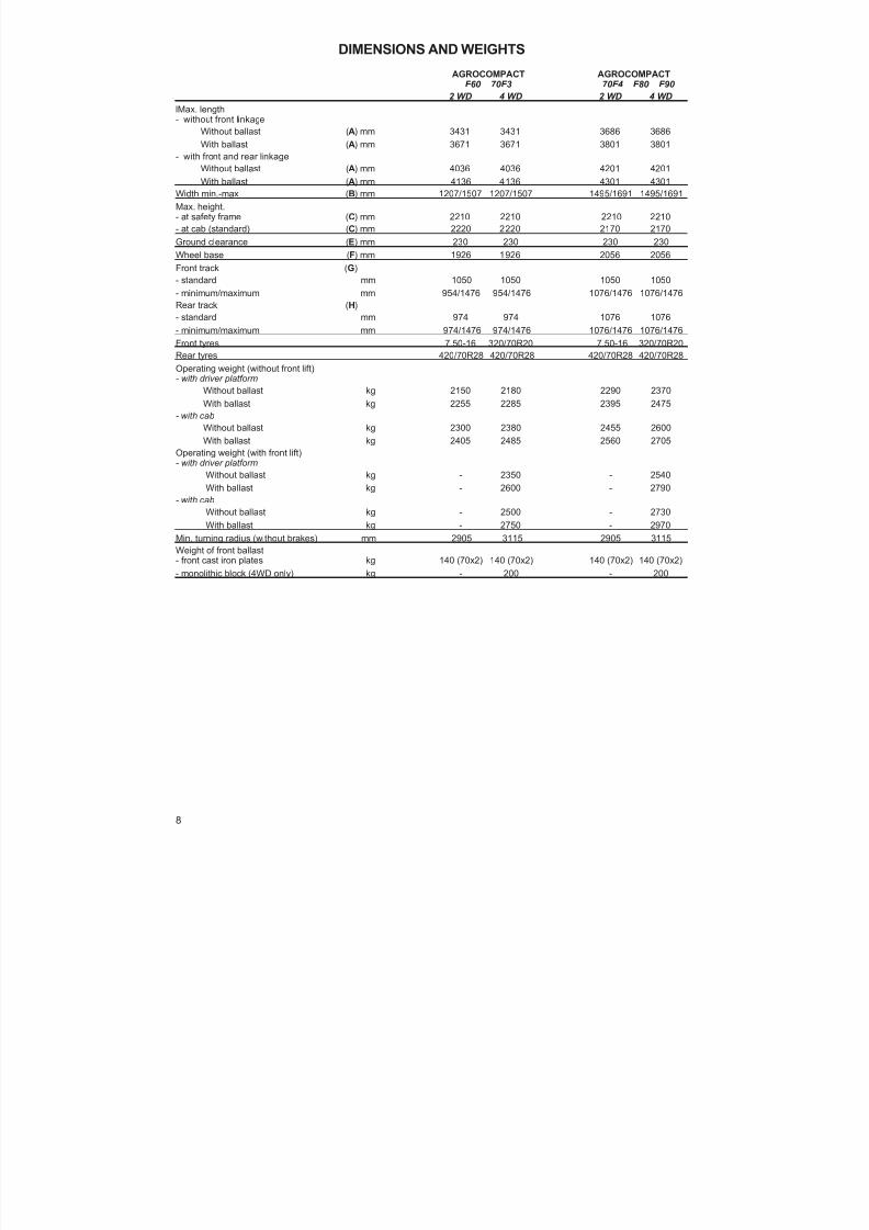
DIMENSIONS AND WEIGHTS
AGROCOMPACT AGROCOMPACTF60 70F3 70F4 F80 F90
2 WD 4 WD 2 WD 4 WD
lMax. length- without front linkage
Without ballast ( A) mm 3431 3431 3686 3686
With ballast ( A) mm 3671 3671 3801 3801- with front and rear linkageWithout ballast ( A) mm 4036 4036 4201 4201With ballast ( A) mm 4136 4136 4301 4301
Width min.-max ( B) mm 1207/1507 1207/1507 1495/1691 1495/1691Max. height.- at safety frame ( C) mm 2210 2210 2210 2210- at cab (standard) ( C) mm 2220 2220 2170 2170Ground clearance ( E) mm 230 230 230 230Wheel base ( F) mm 1926 1926 2056 2056Front track ( G)- standard mm 1050 1050 1050 1050- minimum/maximum mm 954/1476 954/1476 1076/1476 1076/1476Rear track ( H)- standard mm 974 974 1076 1076- minimum/maximum mm 974/1476 974/1476 1076/1476 1076/1476Front tyres 7.50-16 320/70R20 7.50-16 320/70R20Rear tyres 420/70R28 420/70R28 420/70R28 420/70R28Operating weight (without front lift)- with driver platform
Without ballast kg 2150 2180 2290 2370With ballast kg 2255 2285 2395 2475
- with cabWithout ballast kg 2300 2380 2455 2600With ballast kg 2405 2485 2560 2705
Operating weight (with front lift)- with driver platform
Without ballast kg - 2350 - 2540With ballast kg - 2600 - 2790
- with cabWithout ballast kg - 2500 - 2730With ballast kg - 2750 - 2970
Min. turning radius (without brakes) mm 2905 3115 2905 3115Weight of front ballast- front cast iron plates kg 140 (70x2) 140 (70x2) 140 (70x2) 140 (70x2)- monolithic block (4WD only) kg - 200 - 200
8

8/19/2019 Agrocompact f60 f70 f80 f90 Repair manual
http://slidepdf.com/reader/full/agrocompact-f60-f70-f80-f90-repair-manual 9/519
9

8/19/2019 Agrocompact f60 f70 f80 f90 Repair manual
http://slidepdf.com/reader/full/agrocompact-f60-f70-f80-f90-repair-manual 10/519
PRESCRIBED LUBRICANTS AND FUELS
(amounts in litres)
Part to be supplied Amt Oil type
Engine
6,7 *60-70-80HP
11 *90 HP
Oiltype
Grade API CC, CD, CE,
CF-4Grade CCMC D4
Vis-cosityindex
Multigrade engine oilSAE 15W 40
Gearbox andRear axlePower-lift
Auxiliary SystemsHydrostatic steering
41 **
API GL 4
SAE 10W 30 Front P.T.O. 2,5
Front - wheel drive Central axle
• Side reductions
61,5 x 2
Brakes control and clutch max.level ATF DEXRON II
Lubrication points NLGI 2 LITIO/Ca
Fuel tank For tractors F60 - 70F3 - 70F4 - F80 - F9069 litres
For tractors F60 - 70F3 - 70F4 - F80 - F90For tractors with frontal P.T.O. and front lift
58 litres
Radiator antifreeze 11 litres
* Quantity of oil not including filter (with filter +1.5 litres).
** Indicative value, which may vary by a few litres according to the type of gearbox; always check the level on the tran-smission dipstick.
First engine oil change: after 50 hours duty.
Intervals between oil changes: every 250 operating hours for lubricants with API-CC specificationsevery 500 operating hours for lubricants API-CD, API-CE, API-CF-4, CCMC-D4specifications (see following note).
N.B. - Oil change intervals should be halved when:the operating temperature is <10°C (+14°F)the fuel contains more than 0.5% of sulphur “Bio-diesel” fuel is used
IMPORTANT: theoil must bechange dat least once a year, regardless of thenumber of operating hours completed.
It is advisable to always use the same type of oil when replenishing.
10

8/19/2019 Agrocompact f60 f70 f80 f90 Repair manual
http://slidepdf.com/reader/full/agrocompact-f60-f70-f80-f90-repair-manual 11/519
CONVERSION TABLE FROM
FROM TO multiply by:inch cm 2.540cm inch 0.394foot m 0.305
m foot 3.281yard m 0.914m yard 1.094Eng. miles km 1.609km Eng. miles 0.622Sq.in. cm2 6.452cm2 Sq.ft. 0.155Sq.ft. m2 0.093m2 Sq.ft. 10.77Sq.yard m2 0.835m2 Sq.yard 1.197Cu.in. cm3 16.39cm3 Cu.in. 0.061Cu.ft. Liter 28.36Liter Cu.ft. 0.035Cu.yard m3 0.763m3 Cu.yard 1.311Imp.gall. Liter 4.547Liter Imp.gall. 0.220US gall. Liter 3.785Liter US gall. 0.264pint Liter 0.568Liter pint 1.762quart Liter 1.137Liter quart 0.880oz. kg 0.028kg oz. 35.25lb. kg 0.454kg lb. 2.203lb.ft. kgm 0.139kgm lb.ft. 7.233lb/in. kg/m 17.87kg/m lb/in. 0.056lb./sq.in. kg/cm2 0.070kg/cm2 lb/sq.in. 14.22lb./Imp.gall. kg/l 0.100kg/l lb./Imp.gall. 10.00
lb./US gall. kg/l 0.120kg/l lb./US gall. 8.333lb./cu.ft. kg/m3 16.21kg/m3 lb./cu.ft. 0.062cu.ft./lb. m3/kg 0.062m3/kg cu.ft./lb. 16.21Nm kgm 0.102kgm Nm 9.81kW PS 1.36PS kW 0.736bar kg/cm2 1.014kg/cm2 bar 0.981
dm3 l 1l dm3 1
11

8/19/2019 Agrocompact f60 f70 f80 f90 Repair manual
http://slidepdf.com/reader/full/agrocompact-f60-f70-f80-f90-repair-manual 12/519
HOW TO ORDER SPARE PARTS
To ensure perfect tractor efficiency thus avoidingserious drawbacks, and to optimizeyour investment and theoperatio-nal expenses, the use of “ORIGINAL SPARE PARTS” is recommended.Spare parts orders must specify the following:
— Tractor serial number and engine serial number (if the engine is concerned).— Spare part name and reference code.
TRACTOR IDENTIFICATION DATA PLATE
ENGINE TYPE AND SERIAL NUMBER TRACTOR FRAME TYPE AND SERIAL NUMBER
12
8/19/2019 Agrocompact f60 f70 f80 f90 Repair manual
http://slidepdf.com/reader/full/agrocompact-f60-f70-f80-f90-repair-manual 13/519
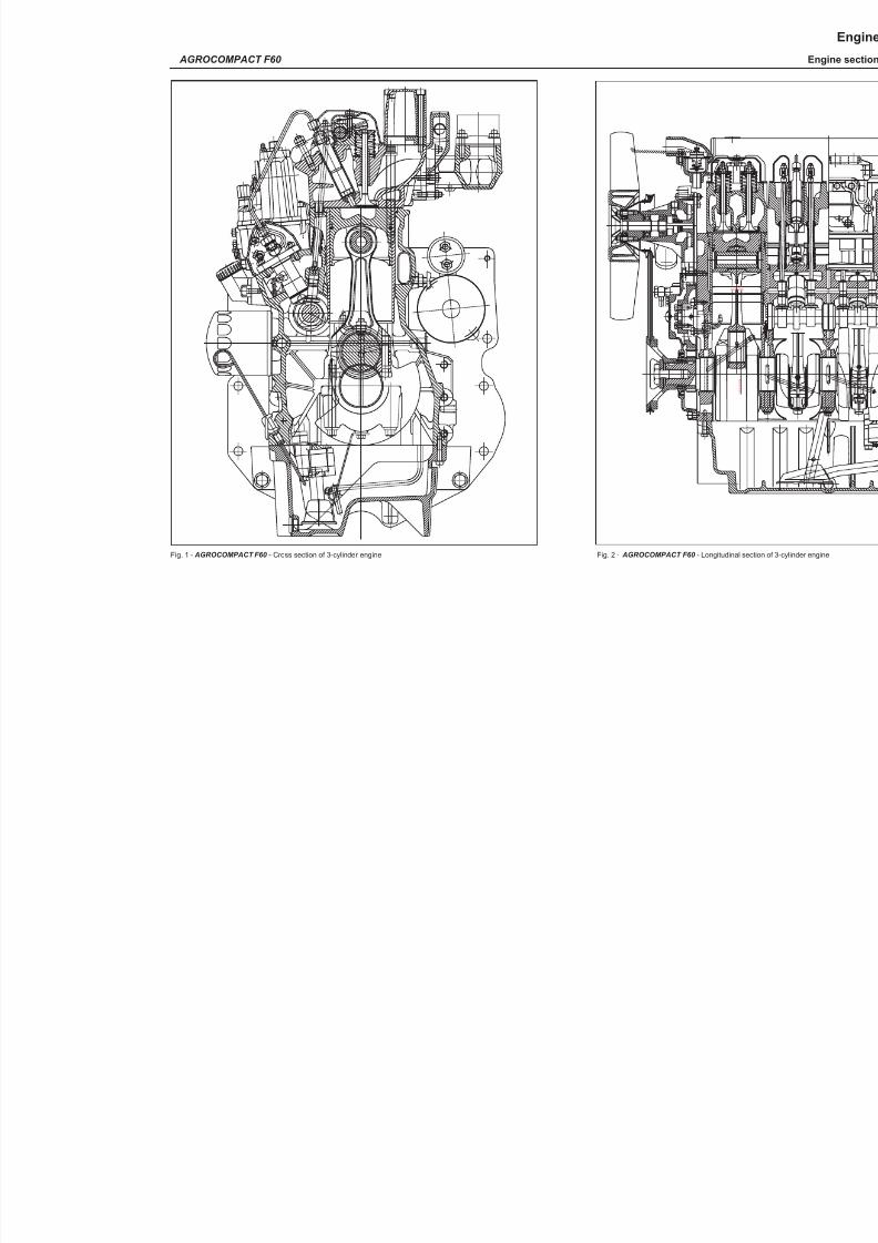
Fig. 1 - AGROCOMPACT F60 - Cross section of 3-cylinder engine Fig. 2 - AGROCOMPACT F60 - Longitudinal s
AGROCOMPACT F60
ALESAGGIOø105
5
. 5 C O R S A

8/19/2019 Agrocompact f60 f70 f80 f90 Repair manual
http://slidepdf.com/reader/full/agrocompact-f60-f70-f80-f90-repair-manual 14/519
Fig. 3 - AGROCOMPACT 70F3 - Cross section of 3-cylinder TURBO engine.
14
Engine
Engine section AGROCOMPACT 70F3
1
8/19/2019 Agrocompact f60 f70 f80 f90 Repair manual
http://slidepdf.com/reader/full/agrocompact-f60-f70-f80-f90-repair-manual 15/519
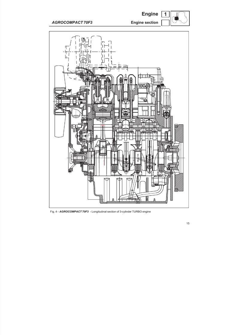
Fig. 4 - AGROCOMPACT 70F3 - Longitudinal section of 3-cylinder TURBO engine
15
1Engine
AGROCOMPACT 70F3 Engine section
ALESAGGIOø105
1 1 5
. 5 C
O R S A
8/19/2019 Agrocompact f60 f70 f80 f90 Repair manual
http://slidepdf.com/reader/full/agrocompact-f60-f70-f80-f90-repair-manual 16/519
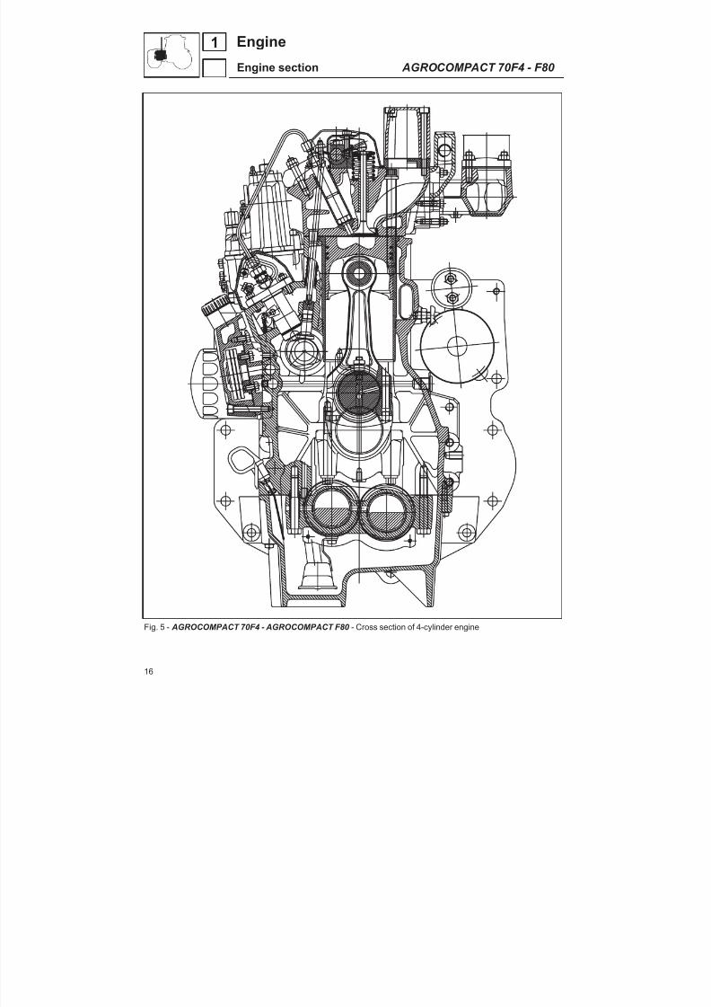
Fig. 5 - AGROCOMPACT 70F4 - AGROCOMPACT F80 - Cross section of 4-cylinder engine
16
1 Engine
Engine section AGROCOMPACT 70F4 - F80
8/19/2019 Agrocompact f60 f70 f80 f90 Repair manual
http://slidepdf.com/reader/full/agrocompact-f60-f70-f80-f90-repair-manual 17/519
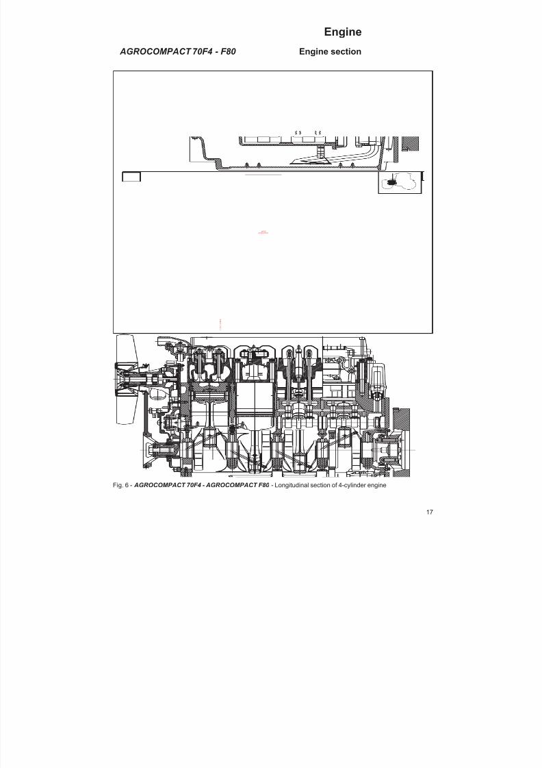
Fig. 6 - AGROCOMPACT 70F4 - AGROCOMPACT F80 - Longitudinal section of 4-cylinder engine
17
Engine
AGROCOMPACT 70F4 - F80 Engine section
ø105 ALESAGGIO
1 1 5
. 5 C O R S A

8/19/2019 Agrocompact f60 f70 f80 f90 Repair manual
http://slidepdf.com/reader/full/agrocompact-f60-f70-f80-f90-repair-manual 18/519
Fig. 7 - AGROCOMPACT F90 - Cross section of 4-cylinder TURBO engine
18
Engine
Engine section AGROCOMPACT F90
1

8/19/2019 Agrocompact f60 f70 f80 f90 Repair manual
http://slidepdf.com/reader/full/agrocompact-f60-f70-f80-f90-repair-manual 19/519
Fig. 8 - AGROCOMPACT F90 - Longitudinal section of 4-cylinder TURBO engine
19
1Engine
AGROCOMPACT F90 Engine section
ø105 ALESAGGIO
1 1 5
. 5 C O R S A

8/19/2019 Agrocompact f60 f70 f80 f90 Repair manual
http://slidepdf.com/reader/full/agrocompact-f60-f70-f80-f90-repair-manual 20/519
AGROCOMPACT F60 70F3 70F4 F80 F90
Tipo 1000.3-W1 1000.3-WT1 1000.4-W4 1000.4-W3 1000.4-WT1ciyle diesel diesel diesel diesel diesel
strokes 4 4 4 4 4
turbocharging - turbo - - turbo
injection DIRECT DIRECT DIRECT DIRECT DIRECT
cylinder No 3 3 4 4 4
cylinder arrangement IN LINE IN LINE IN LINE IN LINE IN LINE
bore and stroke mm 105 x 115,5 105 x 115,5 105 x 115,5 105x115,5 105x115,5stroke / bore ratio 1,1 1,1 1,1 1,1 1,1
displacement cm 3 3000,44 3000,44 4000,44 4000,44 4000,44
compression ratio 17:1 16:1 17:1 17:1 16:1
max. output cv CUNA 60 70 70 80 90
Kw 44 51,5 51,5 58,8 64
peack horsepower speed r.p.m. 2350 2350 2350 2350 2350
max. torque nm 207 250 268 296 325
kgm 21 25,5 21 30 33
specific horsepower cv/l 20 23,3 17,5 20 21,7
cooling by water by water by water by water by water
low idling speed r.p.m. 650-700 650-700 650-700 650-700 650-700
peak speed r.p.m. 2520/2550 2520/2550 2520/2550 2520/2550 2520/2550
minimum lubricating oil pressure
low idling speed (hot oil) bar 0,5 0,5 0,5 0,5 0,5
high idling speed (hot oil) bar 3,5 3,5 3,5 3,5 3,5
oil filter with replaceable cartrige n. 1 1 1 1 1
filtering capacity µ 15 15 15 15 15
fuel filter replaceable cartridge
valve arrangement vertical in-line
20
1 Engine
General information

8/19/2019 Agrocompact f60 f70 f80 f90 Repair manual
http://slidepdf.com/reader/full/agrocompact-f60-f70-f80-f90-repair-manual 21/519
A - Top dead centre (TDC)B - Bottom dead centre (BDC)C - Injection advanceD - Valve overlap
a - Intakeb - Exhaustc - Openingd - Closing
Timing diagram
Timing by overhead valves and camshafitedinto engine block
valve arrangement vertical in-lineintake valve-opening before TDC 14°-closing after BDC 40°exhaust valves-opening before BDC 48°-closing after TDC 12°clearance between valves and rockers(cold engine) mm 0,30injection advance (geometric)before TDC 16°piston stroke as to injection advance mm 2,92
21
1Engine
Timing specification

8/19/2019 Agrocompact f60 f70 f80 f90 Repair manual
http://slidepdf.com/reader/full/agrocompact-f60-f70-f80-f90-repair-manual 22/519
Fig. 9 - Lubrication diagram.
engine type1000.3-W1 1000.4-W3
1000.3-WT1 1000.4-WT1lubrication forced-type, gear pump-dri -ven
by camshaftoil pump 010.5481.4 010.5441.4/10pump delivery rate at 2500 engine r.p.m.
(dm 3/60 secretary) l/min 38 ÷ 42 48 ÷ 51pressure relief valve calibration bar 3,5 ÷ 4,5 3,5 ÷ 4,5piston cooling nozzle calibration bar 1,5 1,5minimum lubricating oil pressure(hot oil)at low idling speed bar 0,5 0,5at high idling speed bar 0,3 0,3oil sump capacity (dm3) l 6.7 11
22
1 Engine
Lubrication system - specifications

8/19/2019 Agrocompact f60 f70 f80 f90 Repair manual
http://slidepdf.com/reader/full/agrocompact-f60-f70-f80-f90-repair-manual 23/519
fuel supply by diaphragm pump
fuel pump ref. Code 2.4519.300.0pump delivery when pressure inside the circuit changesfrom 0 to 0.4 bar and engineis at peak speed (dm 3/h) l/h 100
injection by single-cylinder, immersed-type pumpand camshaft-controlled plungers
- manufacturer BOSCH- type PFR 1K 90 A 543
PFR 1K 90 A 555 (for USA)- number of pumps used 3 cylinder engine 3
4 cylinder engine 4- injection order 3 cylinder engine 1-3-2
4 cylinder engine 1-3-4-2- plunger diameter mm 9- injection system residual calibratingpressure bar 70injectors- manufacturer BOSCH- injector type DLLA 150 S 925- injector holder type KBEL 100S 31- rated calibration pressure bar 180- injection pipe inside diameter mm 1,5cylinder pressure at sea levelat 150 r.p.m. (with hot oil) measured byequipment no. 5.9030.500.6/10 bar 25÷ 30dry air filter - code 8" 2.4249.600.0fuel filter with replaceable paper cartridge- code 2.4319.060.0/10- capacity 1,5 ÷ 2
Engine
Fuel system - specifications
23
1
8/19/2019 Agrocompact f60 f70 f80 f90 Repair manual
http://slidepdf.com/reader/full/agrocompact-f60-f70-f80-f90-repair-manual 24/519
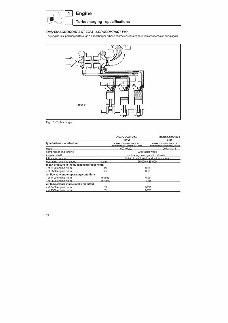
Only for AGROCOMPACT 70F3 AGROCOMPACT F90 The engine is supercharged through a turbocharger, whose characteristics are here you of succession bring again.
Fig. 10 - Turbocharger.
AGROCOMPACT AGROCOMPACT 70F3 F90
type/turbine manufacturer GARRETT T25-45/0.68 A/R 62 GARRETT T25-50/0.68 A/R 76SCHWITZERS 1A/4808DB/0,81MM1 SCHWITZERS 1B/5309W6/0,81GG1
code 007.0720.4 007.1443.4compressor and turbine with radial wheelimpeller shaft on floating bearings with oil sealslubrication system linked to engine oil lubrication systemoperating revolving speed r.p.m. 55.000 ÷ 85.000mean pressure in the duct at compressor exit:- at 1400 engine r.p.m bar 0.25- at 2500 engine r.p.m. bar 0,60air flow rate under operating conditions :- at 1400 engine r.p.m m³/sec 0,06- at 2500 engine r.p.m. m³ 3/sec 0,10air temperature inside intake manifold :- at 1400 engine r.p.m °C 60°C- at 2500 engine r.p.m. °C 90°C
24
1 Engine
Turbocharging - specifications

8/19/2019 Agrocompact f60 f70 f80 f90 Repair manual
http://slidepdf.com/reader/full/agrocompact-f60-f70-f80-f90-repair-manual 25/519
Engine cooling system
The water cooling system is composed of a conventional radiator, a water pump and a thermostat. An external manifold routes the water flow separately to each single cylinder-head-liner unit.Subsequently the water streams through a special inlet opening in the engine block and enters a heat exchanger thus providing for enine lubri -cating oil cooling.
Thethermostat provides uniform temperature control inside thecircuit. When theoperatingtemperature is exceeded, itensures proper temperature regulation by permitting water to flow into the radiator gradually and in small volumes.
A fan, constantly driven by the engine, projects the air stream being necessary for cooling the water which flow acrossthe radiator.
3 cylinders 3 cylinders turbo 4 cylinders 4 cylinders turboFan 6 polypropylene bladesfan diameter 500 500 500 500water pump centrifugal blade centrifugal blade centrifugal blade centrifugal bladeratio of transmission between motor and pomp for basic version 1,179 1,179 1,179 1,179delivery at 2,500 r.p.m. 147 147 147 147delivery head 0,34 0,34 0,34 0,34thermostatquantità 1 1
type WAHLER 4015start opening temperature 85÷ 2maximum opening temperature 95÷2valve stroke 5,5water cooler copper-type with 3 rowsmanufacturer CURLI CURLI CURLI CURLItype with pipe blunles with pipe blunles with pipe blunles with pipe blunlesrated pressure 0,7 0,7 0,7 0,7
Fig. 11 - Cooling system , (in the picture is shown the version for 4 cylinders).
25
1Engine
Cooling system - specifications

8/19/2019 Agrocompact f60 f70 f80 f90 Repair manual
http://slidepdf.com/reader/full/agrocompact-f60-f70-f80-f90-repair-manual 26/519
Fig. 1 - Engine cylinder block
Fig. 2 - Oil chamber for cylinder cooling.
Fig. 3 - Piston cooling nozzles.
Fig. 4 - Piston cooling nozzle assemblywith 5.9030.731.4 tool.
Engine cylinder blockThe one-piece engine cylinder block is a particularly sturdy ca -sting. All oil passages necessary to piston lubrication and coolingare directly machined in it.
Whenever theengine is stripped, ensure that all passages are notobstructed. If necessaryperform a thoroughcleaningby compres -sed air after the block has beensoaked ina water and sodaorDie -sel oil bath for some time, and all passage caps have been remo -ved.
It is most important to make sure that neither the piston coolingnozzles nor the cylinder bottom cooling throats are obstructed asthis could prevent the engine from running smoothly.
If thepiston cooling nozzles have been removed, pay particular at -tention on reassembly so as to avoid any interference with pistonstroke, since this would certainly result in a serious engine dama -ge. For this reason we recommend using the special tool no.5.9030.731.4, enabling the nozzles to be correctly positioned.
NOTE: When installing the fitting of the piston cooling nozzle,apply a small quantity of Loctite 242 to the thread and tighten to atorque of 3 kgm. Fit thenozzle to thefitting, tightening theretainingnut to a torque of 2.5 kgm.
The tappet seat surfaces should be completely smooth.Tappets must be fitted before installing the camshaft and with thecylinder block overturned. After fitting tappets, ensure these canmove freely.
Installing bushings into the camshaft journals Ascertain the camshaft journal bushings are correctly positioned,i.e. thoroughly aligned with theoil passages machined in thecylin -der block.
Bushings should be positioned so that they may recess about 2
mm from the holes in the block, except the last bushing on flywhe -el side which should be flush with the block wall.
Fig. 5 - Camshaft journal bushings.
26
11
1 Engine
Timing case

8/19/2019 Agrocompact f60 f70 f80 f90 Repair manual
http://slidepdf.com/reader/full/agrocompact-f60-f70-f80-f90-repair-manual 27/519
Adjusting backlash between the gear teeth of theauxiliary engine drive.Maximum horsepower drawn should never exceed 30 HP.
Between engine plane and application base fit a number of shimsto allow a 0.1 to 0.2 mm backlash may take place between thegear teeth.The pack of shims should be put together by alternating metallicand isogene shims, the first and the last shims being of isogene(the first metal shim on engine side shall be 0.5 mm). After dismantling the timing case gears, provision shall be madefor a new timing keeping to the instructions given on page 77 prior to reassembly.
Make sure the idler gear shoulder rings are not excessively worn;
also check the pin surface and the gear inside face for scoring.
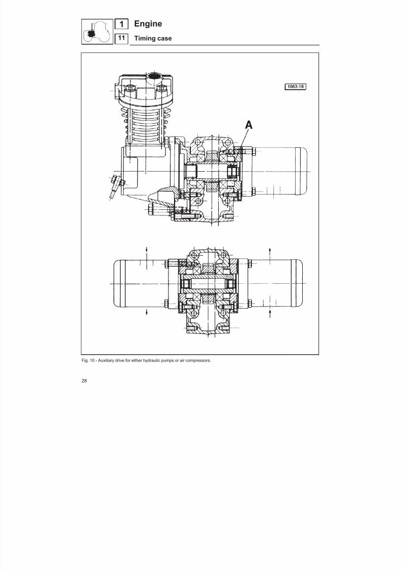
Support for hydraulic pumps or air compressor lo -cated between engine block and timing cover The timing cover is made of lightweight aluminium alloy.Tofit the timingcover, it is essential touse tool5.9030.634.0 toen -sure a perfect alignment between the oil seal and the crankshaftandbetween themating surfaces of theauxiliary power take-off.
Fit the oil seal A in the timing cover with the locating tabs orientedtowards the inside of the cover.Fit thegasket D and timing cover C to the block. Screw in the cover
bolts but do not tighten at this stage.Fit the hub B. Align the mating face of the timing cover with that of the engineblock using tool E 5.9030.634.0, which is to be secured with twobolts to the engine block.Tighten the timing cover bolts in the sequence 1-2-3 and then theall remaining bolts to a torque of 24.5 Nm (2.5 kgm).Remove the tool E and the strip of excess gasket D.
Fig. 6 - Areaon engine block inwhich sealant istobe applied (4650.026.0)
Fig. 7 - Drive gear toothing backlash.
Fig. 8 - Aligning the timing case with the cylinder block
Fig. 9 - Timing case stripped components.
27
11
1Engine
Timing case
8/19/2019 Agrocompact f60 f70 f80 f90 Repair manual
http://slidepdf.com/reader/full/agrocompact-f60-f70-f80-f90-repair-manual 28/519
Fig. 10 - Auxiliary drive for either hydraulic pumps or air compressors.
28
11
1 Engine
Timing case

8/19/2019 Agrocompact f60 f70 f80 f90 Repair manual
http://slidepdf.com/reader/full/agrocompact-f60-f70-f80-f90-repair-manual 29/519
Timing idler geaUse a magnetic base dial gauge to check for correct tooth bac -klash between idler, engine gear and timing gear.
This backlash should not exceed 0.10 mm; otherwise the idler gear should be replaced by another one having the same thic -kness as the tooth located on thedifferentpitch diameter, so that acorrect tooth backlash may be established.
Identification among gears is provided with marks of different co -lours (either RED or YELLOW or GREEN) as illustrated in figure11.
To eachcolour corresponds a well-definedtooth thicknessvalue.
tooth thickness on the pitch diameter
ref. code 007.1177.0 RED colour =3,829 --0 0440 088
,,
ref. code 007.1178.0 YELLOW colour =3,829 --0 0090 053
,,
ref. code 007.1179.0 GREEN colour =3,829 -+0 0180 026,,
A - Idler gear B - Cranshaft driving gear C - Timing driving gear
Fig. 13 - Idler gear
Fig. 11 - Timing idler gear A - Identification mark
Fig. 12 - Gear toothingB - Gear tooth thickness.
29
11
1Engine
Cylinder block
8/19/2019 Agrocompact f60 f70 f80 f90 Repair manual
http://slidepdf.com/reader/full/agrocompact-f60-f70-f80-f90-repair-manual 30/519
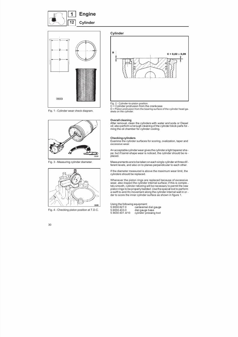
Fig. 1 - Cylinder wear check diagram.
Fig. 3 - Measuring cylinder diameter.
Fig. 4 - Checking piston position at T.D.C.
Cylinder
Fig. 2 - Cylinder-to-piston position.C = Cylinder protrusion from the crankcaseD = Piston protrusion from the bearing surface of the cylinder head ga -skets on the cylinder.
Overall cleaning After removal, clean the cylinders with water and soda or Dieseloil; also perform a torough cleaning of the cylinder block parts for -ming the oil chamber for cylinder cooling.
Checking cylindersExamine the cylinder surfaces for scoring, ovalization, taper andexcessive wear.
An acceptablecylinder wear gives the cylinder a light taperedsha -pe; but if barrel-shape wear is noticed, the cylinder should be re -placed.
Measurements are to be taken on each singlecylinder at three dif -ferent levels, and also on to planes perpendicular to each other.
If the diameter measured is above the maximum wear limit, thecylinders should be replaced.
Whenever the piston rings are replaced because of excessivewear, also inspect the cylinder internal surface; if this is comple -tely smooth, cylinder reboring will be necessary to permit the newpiston rings to be properly bedded.Use thespecial tool to performa swift to-and-fro movement along the cylinder internal wall in or -der to score the inner cylinder surface as shown in figure 1.
Using the following equipment:5.9030.627.0 centesimal dial gauge5.9030.433.0 dial gauge base5.9030.631.4/10 cylinder pressing tool
30
12
1 Engine
Cylinder
8/19/2019 Agrocompact f60 f70 f80 f90 Repair manual
http://slidepdf.com/reader/full/agrocompact-f60-f70-f80-f90-repair-manual 31/519
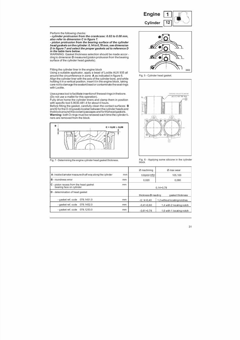
Perform the following checks:- cylinder protrusion from the crankcase: 0.02 to 0.08 mm,also refer to dimension C in figure 7.- piston protrusion from the bearing surface of the cylinder head gaskets on thecylinder: 0,14 to 0,78 mm,see dimensionD in figure 7 and select the proper gaskets ad to reference Din the table here below.WARNING: Gasket thickness selection should be made accor -ding to dimension D measured(piston protrusion from the bearingsurface of the cylinder head gaskets).
Fitting the cylinder liner in the engine blockUsing a suitable applicator, apply a bead of Loctite AUX 935 allaround the circumference in zone A as indicated in figure 6. Align the cylinder liner with the axis of the cylinder bore, and while
holding it in a vertical position, insert it in the engine block, takingcare not to damage thesealant bead or contaminate theseal ringswith Loctite.
Usea press tool to facilitate insertionof theseal rings in thebore.(Do not use a mallet for this operation).Fully drive home the cylinder liners and clamp them in positionwith specific tool 5.9030.481.4 for about 4 hours.Before fitting the gasket, carefully clean the contact surfaces Band C for theO-ringseals located between thecylinder headsandtheblockaround thecoolant passages and for theheadgaskets.Warning: both O-rings must be renewed each time the cylinder li -ners are removed from the block.
Fig. 7 - Determining the engine cylinder head gasket thickness.
A - insidediameter measuredhalf-way along the cylinder mm
B - roundness error mm
C - piston recess from the head gasket mmbearing face on cylinder
D - determination of head gasket
- gasket ref. code 078.1451.0 mm
- gasket ref. code 078.1452.0 mm
- gasket ref. code 078.1253.0 mm
Fig. 5 - Cylinder head gasket.
Fig. 6 - Applying some silicone in the cylinder block.
Ø machining Ø max wear
105000 00 022, ,
-+ 105,100
0,020 0,080
0,14÷0,78
thickness D reading gasket thickness
-0,14÷0,40 1,2 without locatingnotches
-0,41÷0,60 1,4 with 2 locating notch-0,61÷0,78 1,6 with 1 locating notch
31
12
1Engine
Cylinder
8/19/2019 Agrocompact f60 f70 f80 f90 Repair manual
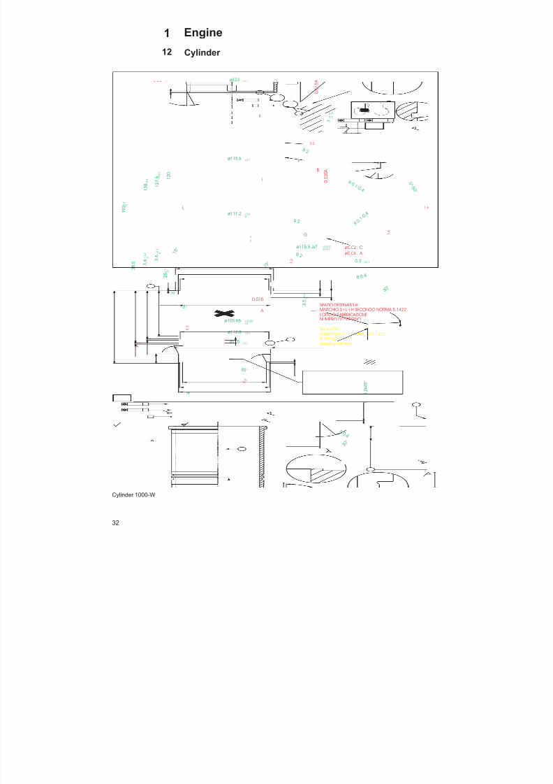
http://slidepdf.com/reader/full/agrocompact-f60-f70-f80-f90-repair-manual 32/519
Cylinder 1000-W
32
12
1 Engine
Cylinder
I
A
B
L
3 . 2
1.6
1 . 6
B
3.2
3 . 2ø0.06 A
ø0.08 A
3 . 2
3 . 2
2.52.5
A
0.015
3
1 5 °
ø0.06 A
C
ø0.02 C
3 . 2
6 . 3
3 8
. 5
= =
0 . 0
1 5 B
0 . 0
2 0 A
: : :
ø 115 ±0.1
0 . 2 - 0 . 4
3 0 °
R 0. 2 - 0. 4
0 . 1 - 0 . 2
x 4 5 °
R 0 .1 - 0 .4
R 0 . 1 -
0 . 4
ø111 ±0.1
ø116 g7 -0.012
-0.047
ø123 ±0.1
1 - 0 . 1 0
ø115.6 ±0.1
7 + 0
. 0 7
+ 0
. 0 4
1 8
+ 0
. 3
0
1 2 7
. 5 ± 0
. 2
1 3 8 ±
0 . 2
3 . 6
+ 0
. 2
0
3 . 6
+ 0
. 2
0
1 2 0
1 9 2 - 0
. 3 0
ø115.5 Js7 +0.017-0.017
ø105 H6 +0.022+0
ø112.8 ±0.1
3 . 5
+ 0
. 3
0
1 5 °
2 5
+ 1
0
G
0 ° - 5
0 °
1 5 °
Space for:
drawing number
SPAZIO DESTINATO A:MARCHIO S+L+H SECONDO NORMA 5.1422LOTTO DI FABBRICAZIONENUMERO DI DISEGNO
Trade Mark S+L+H as CAP.5.1422Building lot
3 0 °
ø115 ±0.1
ø111.2 +0.20
R 0 .4
R 0 . 4
3 0 °
0.3 ±0.1
R 2
R 2
R 2
E
F
8/19/2019 Agrocompact f60 f70 f80 f90 Repair manual
http://slidepdf.com/reader/full/agrocompact-f60-f70-f80-f90-repair-manual 33/519
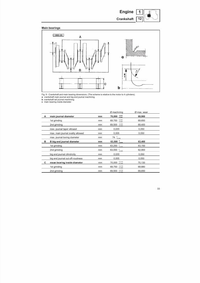
Main bearings
Fig. 9 - Crankshaft and main bearing dimensions. (The scheme is relative to the motor to 4 cylinders).a crankshaft main journal and big end journal machining.b crankshaft tail journal machining.
c main bearing inside diameter
Ø machining Ø max. wear
A main journal diameter mm 70,000 --0 0400 020
,, 69,900
1st grinding mm 69,750 --0 0400 020
,, 69,650
2nd grinding mm 69,500 --0 0400 020
,, 69,400
max. journal taper allowed mm 0,020 0,050
max. main journal ovality allowed mm 0,005 0,050
max. journal boring diameter mm 74 -0 0300 ,
B B big end journal diameter mm 63,500 -0 0200
, 63,400
1st grinding mm 63,250 -0 0200
, 63,150
2nd grinding mm 63,000 -0 0200
, 62,900
big end journal cilindricity mm 0,020 0,050
big end journal out-off-roudness mm 0,005 0,050
C mean bearing inside diameter mm 70,000 ++
0 0680 018
,, 70,130
1st grinding mm 69,750 ++
0 0680 018
,, 69,880
2nd grinding mm 69,500 ++
0 0680 018
,,
69,650
33
12
1Engine
Crankshaft

8/19/2019 Agrocompact f60 f70 f80 f90 Repair manual
http://slidepdf.com/reader/full/agrocompact-f60-f70-f80-f90-repair-manual 34/519
Fig.10 - Crankshaft assembly - 3-cylinder engine
Fig. 11 - Crankshaft assembly - 4-cylinder engine
34
12
1 Engine
Crankshaft
1 1 5
. 5 C O R S A
1 1 5
. 5 C O R S A

8/19/2019 Agrocompact f60 f70 f80 f90 Repair manual
http://slidepdf.com/reader/full/agrocompact-f60-f70-f80-f90-repair-manual 35/519
CrankshaftThe crankshaft is in nodular cast iron.
All operations must be carried out in compliance with the following standards:
1 - Metalloscope inspection of 100% of pieces; cracksare not permissible.
2 - When grinding the crankshaft, it should preferablyrotate in the opposite direction to its normal rotation inthe engine, but rotation in the same direction is per -missible.
During the polishing operation, however, thecrankshaft must rotate only in the same direction as it
normally rotates in the engine.
The surfaces must be polished and totally free of ma -chining marks.NB: the permitted values for crankshaft grinding are gi -ven on page 33.
3 - The emerging Ø6 mm oilways must be chamferedwith a radius of 1.5 mm, and these chamfers must befree from machining marks.
4 - Round off all sharp edges.
5 - The crankshaft (complete with ring gear, in thecase of 4-cylinder engines) and Ø12 mm dowel, mustbe balanced both statically and dynamically. The ma -ximum permissible unbalance on the end supports is150 g cm.
6 - Before assembly, degrease and thoroughly cleanthe crankshaft, including the oilways.
Fig. 11 - 4-cylinder engine crankshaft cross-section
35
1Engine
Crankshaft 12

8/19/2019 Agrocompact f60 f70 f80 f90 Repair manual
http://slidepdf.com/reader/full/agrocompact-f60-f70-f80-f90-repair-manual 36/519
Fig. 13 - Cleaning crankshaft lubricating holes.
Fig. 14 - Checking crankshaft dimensions.
Fig. 15 - Checkingmain bearing insidediameter.
Fig. 16 - Checking crankshaft end play.
Crankshaft end play is adjusted by two-part spacer rings (see alsospecifications table) fitted onto the rear main bearing sides (flywhe -el side); these are provided with a projection preventing faulty as -sembly, theringscanbemounted after crankshaft installationtoo.
Each main bearing consists of twoshells each being provided with asmall tonguepermitting it tobeheld inposition inside the bearing capseat. The upper bearing shell is provided with a cavity for oil flow.Main bearing caps shall be positioned according to the numberingprinted on their bodies and fixed to the block with two special secu -ring screws, whichcanonly bereplacedwithotheroriginal screws.
Checking crankshaft After the crankshaft has been thoroughly cleaned examine it carefully.
Meticulously ascertain the main and big end journals do not showsigns of seizure, otherwise rigrinding will be necessary. If the jour -nals are cracked the crankshaft shall be replaced.
Using a micrometer gauge make sure the main journal diametersarenotbelowthespecifications given in therelated table,otherwi -se a regrinding should be performed.
Checking crankshaft journal out-of-roundnessand tapeWith a micrometer gauge measure crankshaft journal taper andout-of-roundness amounts; if reading exceed the maximum allo -wances specifieda regrinding shall be performed. (Refer to speci -fication table).
Checking main bearingsClean main bearings carefully and then examine the internal sur -faces for indentation, scuffing, scratching or evident antifriction li-ning wear. If any replace the main bearings.
Checkmain bearing insidediameterswith an internal comparator.If the diameters are found in excess of the maximum wear limits,the main bearings shall be replaced.
Main bearings are supplied as spare parts either with normal sizeor undersize insidediameters. The insidediameter undersize ran -ge is 0.25 to 0.50 mm.
Be very careful when installing themain bearings in order they canbecorrectlypositioned. The bearingshellsprovidedwith a lubrica -ting hole must be placed in the upper side (i.e. into the block for -ging and not into the main bearing caps).
Mounting main bearing capsThe numbers stamped on the main bearing caps must be on thesame side as those stamped on the block.Carefully check main bearing capfixingscrews for stretching, if soreplace them with original screws only.
The screws are to betightened progessively to1 kgm (9.8Nm) tor -que and subsequently to 3 kgm (30 Nm) torque then using no.5.9030.640.0 tool furtherly tighten each single screw to an angleof 55°±1’.
36
12
1 Engine
Crankshaft

8/19/2019 Agrocompact f60 f70 f80 f90 Repair manual
http://slidepdf.com/reader/full/agrocompact-f60-f70-f80-f90-repair-manual 37/519
Cleaning crankshaft and cylinder block internalpassagesCleaning of the lubricating oil passage should be made after allcrankshaft and cylinder block overhauling operations have beenaccomplished.This cleaning can be carried out by using Diesel fuel or compres -sed air blasted into the passages
Checking crankshaft end play (Fig. 16).This check is performed with a magnetic base comparator opera -ting as follows:
— place themagnetic base together with thecomparator onto thecrankcaseandthen make thecomparator feeler contact oneof the crankshaft ends.
— use a lever to move the crankshaft axially towards the compa -rator side until the comparator hand stops moving.
— reset thecomparator and push thecrankshaft with the lever to -wards the opposite side and then take the end play readingfrom the comparator dial.
This reading should be 0.10 to 0.27 mm; if higher than specified,some spacing half-rings with 0.10 to 0.20 mm oversize with re -spect to the nominal thickness shall be fitted. These half-rings areregularly supplied as spare parts.
Triangular-section gaskets should protrude as shown in figure 17.
(Dopoil posizionamento nel casodi sostituzione delle guarnizioni,tagliare la parte eccedente)Sigillare la zona lato coppa olio Engine e la zona carter anteriorecon silicone tipo DIRKO TRASPARENT della ditta Erling.
In its rear portion the crankshaft is provided with a 3x30° chamfer. Inaddition thesurfacecontactingthesealing ringhasundergonea har -dening process.The oil seal must be fitted using tool 5.9030.628.0.
Fig. 17 - Main bearing cap gasket installation.
Fig. 18 - Special fixture for piston positioning du -ring crankshaft installation.
Fig. 19 - Mounting one holed main bearing shellinto the cylinder block forging.
Fig. 20 - Fitting the one main bearing shell intothe main bearing cap.
Fig. 21 -Installing the crankshaft main bearingcaps.
37
12
1Engine
Crankshaft

8/19/2019 Agrocompact f60 f70 f80 f90 Repair manual
http://slidepdf.com/reader/full/agrocompact-f60-f70-f80-f90-repair-manual 38/519
Fig. 22 - Fitting bushing into the con-rod smallend.
Fig. 23 - Checking con-rod for wear.
Fig. 24 - Pulling out/driving in con-rod bushing.
Fig. 25 - Checking thediameter of theconnectingrod clamp bolts.
Connecting rods - connecting rod bearings andbushings (Fig. 26)Checking connecting rod axis parallelism(using no. 5.9030.651.4 special tool)Place the connecting rod on the special tool and mount thecomparator by loading the feeler 1 mm against the gudgeonpin.Move the connecting rod from right to left and reset the compara -tor to zero when thecomparator hand indicates themaximum rea -ding. Remove the connecting rod from the tool and replace it after a 180° rotation along its longitudinal axis.Repeat this operation and note the difference in reading compa -redwith theprevious taken. If thedifference is abovethespecifiedtolerances, the rod shall be straightened by hand press.
Checking connecting rod bushing and bearingsCheck connecting rod bushings and bearings for scoring or scuffing. Wear amountshould notexceedspecifications,otherwise theymust be replaced. After fittingthe bushing,check that the diameter is as specified in figure22.
Checking connecting rod weightThe difference in weight between one engine connecting rod andanother must never exceed 20 gr.
Installing connecting rodsThescrews are to be tightenedprogessivelyto 1 kgm(9.8Nm)torque andsubsequently to 3 kgm(29.5 Nm) torque then using no. 5.9030.640.0 tool
furtherly tighten each single screw to an angle of 90°±1’If these bolts are to be reused, check that the difference betweenthe maximum and minimum diameter measured at the part deno -ted A (Fig25) is less than0,1 mm. If not, the bolt must bereplaced.
Fig. 26 - Checking con-rod axis parallelism.
Ø machining Ø max wear
connecting rod bearing inside diameter mm 63,500 ++
0 0750 035
,, 63,620
1st undersize mm 63,250 ++
0 0750 035
,, 63,370
2st undersize mm 63,000 ++
0 0750 035
,, 63,120
connecting rod bushing inside diameter mm 35 ++
0 0250 015
,, 35,060
maximum misalignment of the connectingrod smoll end axis (measured at 49 mm from con-rod centre line) 0,05 mm
38
12
1 Engine
Crankshaft
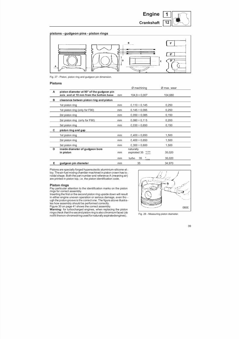
8/19/2019 Agrocompact f60 f70 f80 f90 Repair manual
http://slidepdf.com/reader/full/agrocompact-f60-f70-f80-f90-repair-manual 39/519
pistons - gudgeon pins - piston rings
Fig. 27 - Piston, piston ring and gudgeon pin dimension.
PistonsØ machining Ø max. wear
A piston diameter at 90° of the gudgeon pinaxis and at 10 mm from the bottom base mm 104,9 ± 0,007 104,680
B clearance betwen piston ring and piston
1st piston ring mm 0,110 ÷ 0,145 0,250
1st piston ring (only for F90) mm 0,145 ÷ 0,095 0,250
2st piston ring mm 0,050 ÷ 0,085 0,150
2st piston ring (only for F90) mm 0,080 ÷ 0,115 0,200
3st piston ring mm 0,030 ÷ 0,650 0,150
C piston ring and gap
1st piston ring mm 0,400 ÷ 0,650 1,500
2st piston ring mm 0,400 ÷ 0,650 1,500
3st piston ring mm 0,300 ÷ 0,600 1,500D inside diameter of gudgeon bore naturally
in piston mm aspirated 35 ++
0 0120 006
,, 35,020
mm turbo 35 -0 0060
, 35,020
E gudgeon pin diameter mm 35 34,970Pistons are specially forged hypereutectic aluminium-silicone-al -loy. Theair-fuel mixingchamber machined in piston crown has to -roidal shape. Both the part number and reference A (meaning air)are printed in piston top, i.e. the piston identification code.
Piston ringsPay particular attention to the identification marks on the pistonrings for correct assembly.Inserting the first or the second piston ring upside down will resultin either engine uneven operation or serious damage, even tho -ugh the piston groove is the correct one. The figure above illustra -tes how assembly should be performed correctly.Figure 30 on page 41 shows the correct assembly.Warning: for turbocharged engines, when replacing the pistonrings check that the second piston ring is also chromium faced (donotfit thenon-chromedringused fornaturallyaspiratedengines). Fig. 28 - Measuring piston diameter.
39
12
1Engine
Crankshaft
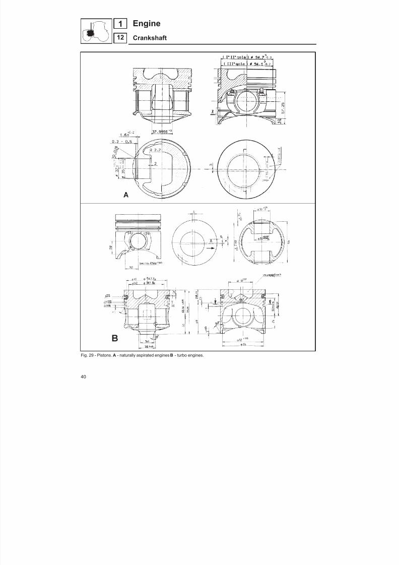
8/19/2019 Agrocompact f60 f70 f80 f90 Repair manual
http://slidepdf.com/reader/full/agrocompact-f60-f70-f80-f90-repair-manual 40/519
Fig. 29 - Pistons. A - naturally aspirated engines B - turbo engines.
40
12
1 Engine
Crankshaft

8/19/2019 Agrocompact f60 f70 f80 f90 Repair manual
http://slidepdf.com/reader/full/agrocompact-f60-f70-f80-f90-repair-manual 41/519
Fig. 30 - Instructions for fitting piston rings to pistons. A - naturally aspirated engines B - turbo engines
41
12
1Engine
Crankshaft

8/19/2019 Agrocompact f60 f70 f80 f90 Repair manual
http://slidepdf.com/reader/full/agrocompact-f60-f70-f80-f90-repair-manual 42/519
Fig. 31 - Checking clearance between pistonrings and piston ring grooves in piston.
Fig. 32 - Checking clearance between the pistonrings and grooves
Fig. 33 - Correct assembly of piston rings.
Cleaning pistonsDescale piston crown and piston ring grooves using an emery
cloth.
Remove any buildups from gudgeon snap ring seats.
After all parts have been thoroughly cleaned and before further checking is performed, examine them carefully for cracking or da -mage which may require replacement.
Light scoring o seizing signs can be removed with very fine emerycloth.
Checking pistonsMeasure piston diameter with a micrometer gauge as shown in fi -gure 28.
If thediameter measured is below the specifications given in tableon page 39, the piston needs to be replaced.
Checking gudgeon pin and gudgeon pin seat in pi -stonIf either gudgeon or related seat diameter measurement differsfrom specifications given in table on page 39, the replacement of the worn-out part is recommended.
Check also gudgeon pin snap rings for proper elasticity or dama -ge. If they are found not conforming to theoperating conditions re-place them.
Checking piston ring end gapBoth the compression ring and the oil control ring ends installed inthe cylinder should not have a gap exceeding the specificationsshown in tableon page 39.
This check is carried out by inserting the piston rings into the cylin -der so as the ring end gap can bemeasuredwith no. 5.9030.270.0special thickness gauge, as shown in figure 31.
NOTE - Excessive clearancebetween piston rings and piston ringgrooves in piston may cause high lubricant consumption as wellas engine power loss.
Piston rings must be replaced each time piston is removed or cylinders are replaced.
42
12
1 Engine
Crankshaft

8/19/2019 Agrocompact f60 f70 f80 f90 Repair manual
http://slidepdf.com/reader/full/agrocompact-f60-f70-f80-f90-repair-manual 43/519
Checking clearance between piston rings and pi -ston ring grooves in pistonThis check is to be made with new piston rings, as shown in figure32, by inserting the piston ring into the groove and then the bladeof no. 5.9030.270.0 thickness gauge. Refer to specifications tableon page 39, for maximum clearance allowance. If the clearancemeasured exceeds the maximum allowance, piston shall be re -placed.
Installing piston ringsDuring cylinder assembly perform a proper orientation of the firstpiston ring so that its cut be moved by 60° from the gudgeon pinaxis.The other piston rings should be inserted with their cuts moved by120° from each other.
Installing pistons into cylindersUse no. 5.9030.654.0 ring clamping band as shown in figure 34 toinstall piston into the cylinder. Afterwards insert piston and cylinder assemblies into the cylinder block.
NOTE - Pistons can be taken without removing the crankshaft, just withdrawing along with the connecting rods directly from thecylinders after removing both cylinder heads and connecting rodcaps.
Before installing the cylinder liners, fit the O-ring seals code2.1519.096.0/20.
The connecting rod-piston assembly must be assembled with thepiston crown recess oriented towards the tappets (Fig. 36).
The big-end caps must be fitted so that the punched number ap -pears on the same side as the number on the connecting rod.
Fig. 34 - Installing piston into cylinder
Fig. 35 - Installing piston into cylinder
Fig. 36 - Correct orientation of piston andcon-rod assembly
43
12
1Engine
Crankshaft
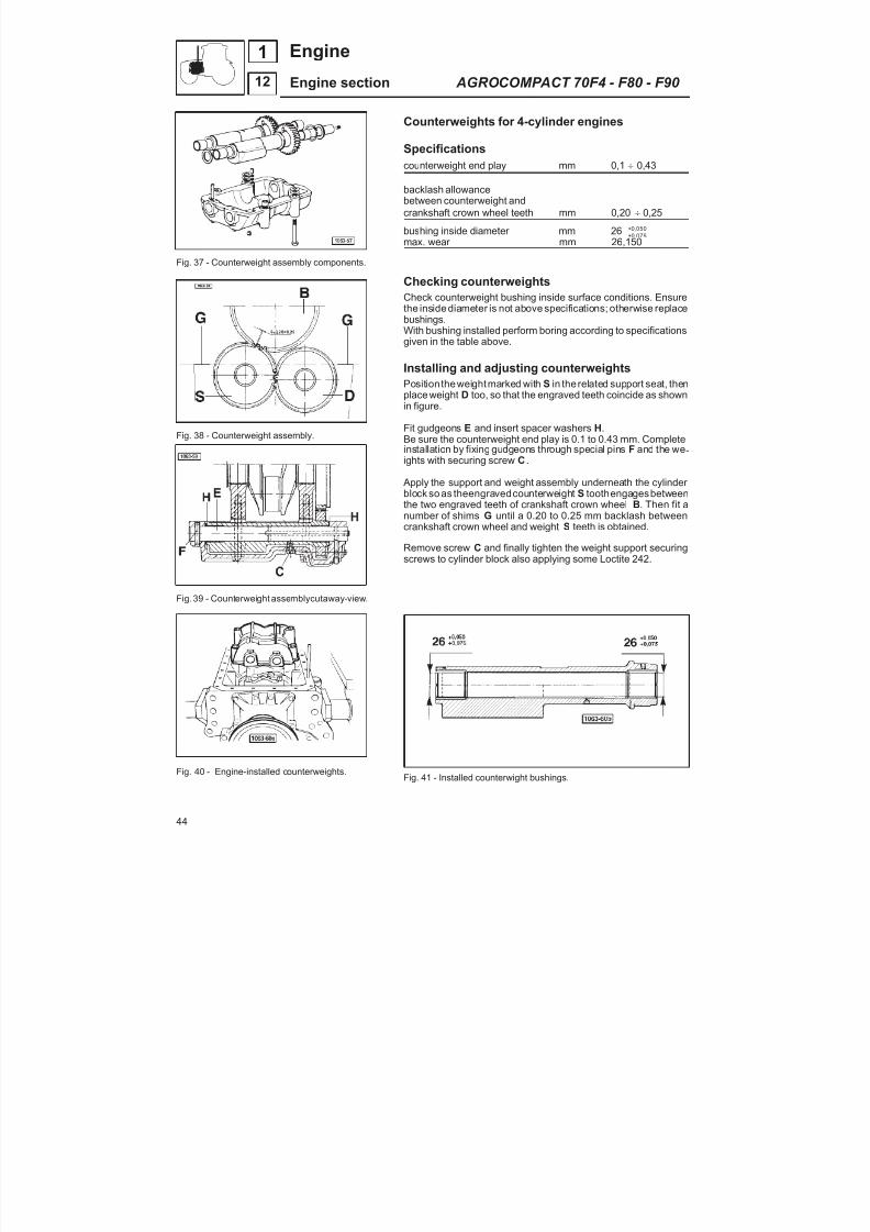
8/19/2019 Agrocompact f60 f70 f80 f90 Repair manual
http://slidepdf.com/reader/full/agrocompact-f60-f70-f80-f90-repair-manual 44/519
Fig. 37 - Counterweight assembly components.
Fig. 38 - Counterweight assembly.
Fig.39 - Counterweight assemblycutaway-view.
Fig. 40 - Engine-installed counterweights.
Counterweights for 4-cylinder engines
Specificationscounterweight end play mm 0,1 0,43
backlash allowancebetween counterweight andcrankshaft crown wheel teeth mm 0,20 0,25
bushing inside diameter mm 26 ++
0 0750 050
,,
max. wear mm 26,150
Checking counterweights
Check counterweight bushing inside surface conditions. Ensurethe inside diameter is not above specifications; otherwise replacebushings.With bushing installed perform boring according to specificationsgiven in the table above.
Installing and adjusting counterweightsPosition theweightmarked with S in the related support seat, thenplace weight D too, so that the engraved teeth coincide as shownin figure.
Fit gudgeons E and insert spacer washers H.Be sure the counterweight end play is 0.1 to 0.43 mm. Completeinstallation by fixing gudgeons through special pins F and the we -ights with securing screw C .
Apply the support and weight assembly underneath the cylinder block so as theengravedcounterweight S toothengagesbetweenthe two engraved teeth of crankshaft crown wheel B. Then fit anumber of shims G until a 0.20 to 0.25 mm backlash betweencrankshaft crown wheel and weight S teeth is obtained.
Remove screw C and finally tighten the weight support securingscrews to cylinder block also applying some Loctite 242.
Fig. 41 - Installed counterwight bushings.
44
12
1 Engine
Engine section AGROCOMPACT 70F4 - F80 - F90
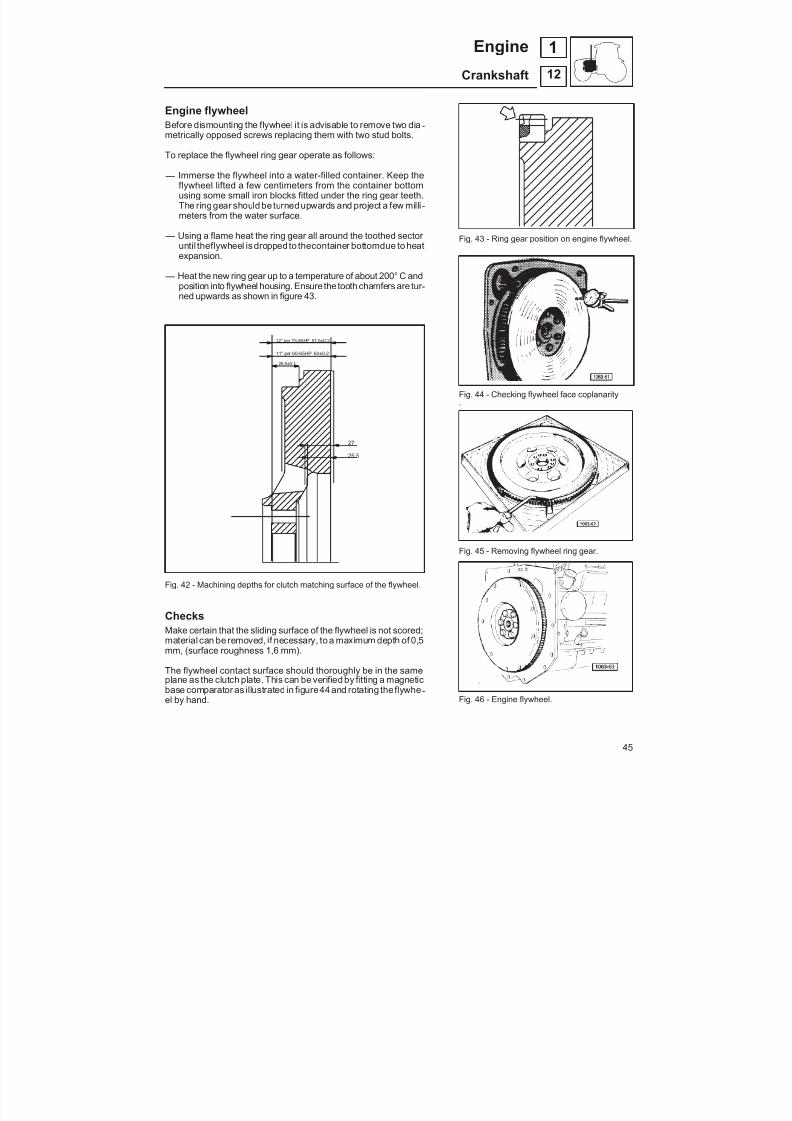
8/19/2019 Agrocompact f60 f70 f80 f90 Repair manual
http://slidepdf.com/reader/full/agrocompact-f60-f70-f80-f90-repair-manual 45/519
Engine flywheelBefore dismounting the flywheel it is advisable to remove two dia -metrically opposed screws replacing them with two stud bolts.
To replace the flywheel ring gear operate as follows:
— Immerse the flywheel into a water-filled container. Keep theflywheel lifted a few centimeters from the container bottomusing some small iron blocks fitted under the ring gear teeth.The ringgear should be turnedupwards and project a few milli -meters from the water surface.
— Using a flame heat the ring gear all around the toothed sector until theflywheel is dropped to thecontainer bottomdue to heatexpansion.
— Heat the new ring gear up to a temperature of about 200° C andposition into flywheel housing. Ensure the tooth chamfers are tur -ned upwards as shown in figure 43.
Fig. 42 - Machining depths for clutch matching surface of the flywheel.
ChecksMake certain that the sliding surface of the flywheel is not scored;material can be removed, if necessary, to a maximum depth of 0,5mm, (surface roughness 1,6 mm).
The flywheel contact surface should thoroughly be in the sameplane as the clutch plate. This can be verified by fitting a magneticbase comparator as illustrated in figure44 and rotating theflywhe -el by hand.
Fig. 43 - Ring gear position on engine flywheel.
Fig. 44 - Checking flywheel face coplanarity.
Fig. 45 - Removing flywheel ring gear.
Fig. 46 - Engine flywheel.
12" per 75-85HP 57,5±0,2
11" per 60-65HP 60±0,2
26,5±0,1
27
25,5
45
12
1Engine
Crankshaft
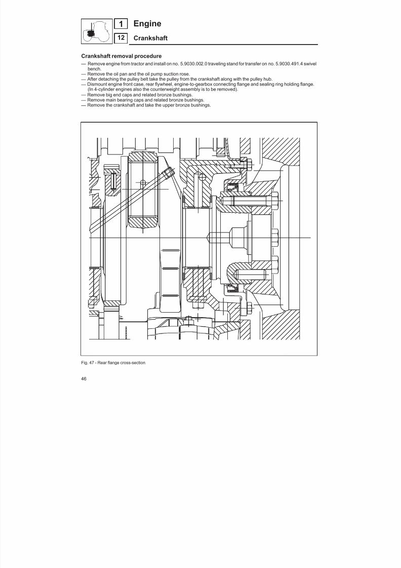
8/19/2019 Agrocompact f60 f70 f80 f90 Repair manual
http://slidepdf.com/reader/full/agrocompact-f60-f70-f80-f90-repair-manual 46/519
Crankshaft removal procedure — Remove engine from tractor and install on no. 5.9030.002.0 traveling stand for transfer on no. 5.9030.491.4 swivel
bench. — Remove the oil pan and the oil pump suction rose. — After detaching the pulley belt take the pulley from the crankshaft along with the pulley hub. — Dismount engine front case, rear flywheel, engine-to-gearbox connecting flange and sealing ring holding flange.
(In 4-cylinder engines also the counterweight assembly is to be removed). — Remove big end caps and related bronze bushings. — Remove main bearing caps and related bronze bushings. — Remove the crankshaft and take the upper bronze bushings.
Fig. 47 - Rear flange cross-section.
46
12
1 Engine
Crankshaft
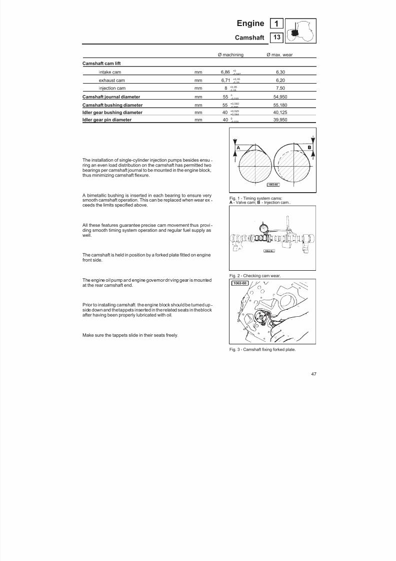
8/19/2019 Agrocompact f60 f70 f80 f90 Repair manual
http://slidepdf.com/reader/full/agrocompact-f60-f70-f80-f90-repair-manual 47/519
Ø machining Ø max. wear
Camshaft cam lift
intake cam mm 6,86 -+0 0870, 6,30
exhaust cam mm 6,71 -+0 050 05,, 6,20
injection cam mm 8 -+0 050 05,, 7,50
Camshaft journal diameter mm 55 -0 0300
, 54,950
Camshaft bushing diameter mm 55 -+0 0900 060,, 55,180
Idler gear bushing diameter mm 40 ++
0 0640 025
,, 40,125
Idler gear pin diameter mm 40 -0 0250
, 39,950
The installation of single-cylinder injection pumps besides ensu -ring an even load distribution on the camshaft has permitted twobearings per camshaft journal to be mounted in the engine block,thus minimizing camshaft flexure.
A bimetallic bushing is inserted in each bearing to ensure verysmooth camshaft operation. This can be replaced when wear ex -ceeds the limits specified above.
All these features guarantee precise cam movement thus provi -ding smooth timing system operation and regular fuel supply aswell.
The camshaft is held in position by a forked plate fitted on enginefront side.
The engine oilpump and engine governordriving gear is mountedat the rear camshaft end.
Prior to installing camshaft, the engine block should be turned up -side down and thetappets inserted in therelated seats in theblockafter having been properly lubricated with oil.
Make sure the tappets slide in their seats freely.
Fig. 1 - Timing system cams:
A - Valve cam; B - Injection cam..
Fig. 2 - Checking cam wear.
Fig. 3 - Camshaft fixing forked plate.
47
13
1Engine
Camshaft
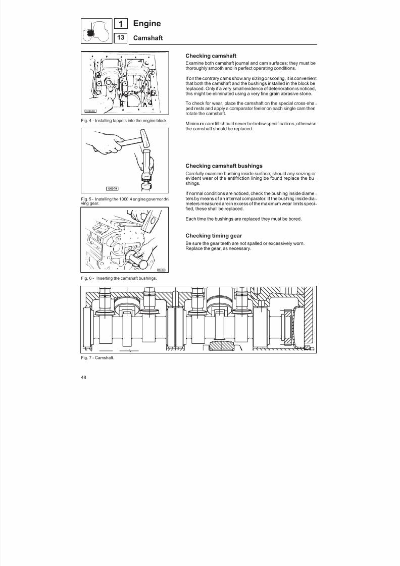
8/19/2019 Agrocompact f60 f70 f80 f90 Repair manual
http://slidepdf.com/reader/full/agrocompact-f60-f70-f80-f90-repair-manual 48/519
Fig. 4 - Installing tappets into the engine block.
Fig. 5 - Installing the 1000.4 engine governor dri -ving gear.
Fig. 6 - Inserting the camshaft bushings.
Fig. 7 - Camshaft.
Checking camshaftExamine both camshaft journal and cam surfaces: they must be
thoroughly smooth and in perfect operating conditions.
If on the contrary cams show any sizing or scoring, it is convenientthat both the camshaft and the bushings installed in the block bereplaced. Only if a very small evidence of deterioration is noticed,this might be eliminated using a very fine grain abrasive stone.
To check for wear, place the camshaft on the special cross-sha -ped rests and apply a comparator feeler on each single cam thenrotate the camshaft.
Minimum cam lift should never be below specifications, otherwisethe camshaft should be replaced.
Checking camshaft bushingsCarefully examine bushing inside surface; should any seizing or evident wear of the antifriction lining be found replace the bu -shings.
If normal conditions are noticed, check the bushing inside diame -ters by means of an internal comparator. If the bushing inside dia -
meters measuredare in excessof themaximum wear limits speci -fied, these shall be replaced.
Each time the bushings are replaced they must be bored.
Checking timing gear Be sure the gear teeth are not spalled or excessively worn.Replace the gear, as necessary.
48
13
1 Engine
Camshaft

8/19/2019 Agrocompact f60 f70 f80 f90 Repair manual
http://slidepdf.com/reader/full/agrocompact-f60-f70-f80-f90-repair-manual 49/519
Cylinder heads - valves - valve rockersØ machining Ø max.wear x
naturally aspirated turbo
A valve stem diameter intake mm 9 --0 0280 013
,, 8,98 0
0 04 – , 8,940exhaust mm 9 -
-0 0280 013
,, 8,96 –0 02, 8,940
B inside diameter the valve guides installed in the heads mm 9 9,100C valve seat angle with respect to valve
intake 29°30’ -150
exhaust 44°30’ -150 44°22’ –7 30' "
D valve seat width on the valve seat insertintake mm 0,8 -
+0 10 5,, 1,8
exhaust mm 1 -+0 10 5,, 2
E valve recess from cylinder head level
intake mm 1,55 1,7exhaust mm 2,20 2,35
F valve seat taper intake 60° -150
exhaust 45° -150
G valve diameter intake 44,2 44,1exhaust 39,5 39,4
Fig. 1 - Main dimensions of valves and valve seat inserts.
Fig. 2 - Rocker support assembly cross-section. Fig. 3 - Engine cylinder head longitudinal section.
49
14
1Engine
Cylinder head
A S
F
E
C
D
G
A
G
B
F
CE
D
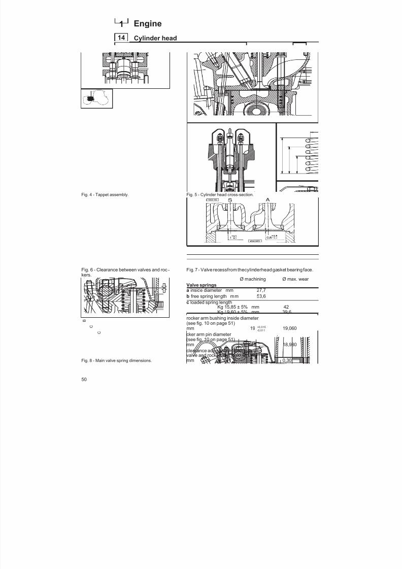
8/19/2019 Agrocompact f60 f70 f80 f90 Repair manual
http://slidepdf.com/reader/full/agrocompact-f60-f70-f80-f90-repair-manual 50/519
Fig. 4 - Tappet assembly.
Fig. 6 - Clearance between valves and roc -
kers.
Fig. 8 - Main valve spring dimensions.
Fig. 5 - Cylinder head cross-section.
Fig. 7 - Valve recessfrom thecylinderheadgasket bearing face.
Ø machining Ø max. wear Valve springsa inside diameter mm 27,7b free spring length mm 53,6c loaded spring length
Kg 15,85 ± 5% mm 42Kg 19,60 ± 5% mm 39,6
rocker arm bushing inside diameter (see fig. 10 on page 51)mm 19 -
+0 0110 015,, 19,060
cker arm pin diameter (see fig. 10 on page 51)
mm 19 -0 0110
, 18,980clearance adjustment betweenvalve and rocker arm (cold)mm 0,30
50
14
1 Engine
Cylinder head
B
C
C
A

8/19/2019 Agrocompact f60 f70 f80 f90 Repair manual
http://slidepdf.com/reader/full/agrocompact-f60-f70-f80-f90-repair-manual 51/519
Cleaning cylinder headsClean the cylinder heads thoroughly by removing any coking insi -de both exhaust and intake ducts. Also clean cylinder head coo -ling fins carefully.
Checking valve seatsFirst descale and clean valve seats and then inspect for either pit -ting or corrosion in the valve contact area, otherwise a new grin -ding (if light wear is found) or a replacement shall be provided.
To install new valve seat inserts operate as follows:chill thevalve seat inserts in liquidnitrogen foreasier installationinthe cylinder head by running fit.Valve seat inserts are supplied as finished parts and do not requi -re any further machining. On installation avoid knocking on thevalve seats to prevent distortion.
NOTE - If no liquidnitrogenis availablefor valve seat insertchillingbefore installation, it is also possible to heat up the cylinder headto a temperature of 200° to 300°C.
Checking valvesDescale the valves with the special brush.Make sure thevalveseat is thoroughly intact, otherwisereplace.Check the valve stem for deformation, be sure the stem outsidediameter is not below specifications.
Testing valve tightness After grinding the valve seats, test valve tightness as follows: plugthe intake and exhaust ports through the related valves and thenpour in some petrol and check for any leaks (if new valves are in -stalled a slight dripping is allowed).
Checking valve guidesInspect valve guide boring inside surface. It should be thoroughlysmooth and show no evidence either of seizing or scoring.
Use no. 5.9030.020.0 gauge (fig. 17) for measuring the valve gui -de inside diameter. Excessively worn guides are to be replaced.When re-installing the valve guides they should protrude14.5 0.2 mm from the seat in the cylinder head.
Using tool specific for installation will enable this dimension to beautomatically obtained.
Fig. 9 - Cylinder heads, cylinders, valves androckerarms.(it haspresented in figure thega -sket for 4 cylinders.
Fig. 10 - Bushing and rocker arm positionsand wear check dimensions.
A - Rocker arm bushing inside diameter.B - Rocker arm pin outside diameter.
Fig. 11 - No.5.9030.635.0 tool for tappet rodcap removal.
A
B
51
14
1Engine
Cylinder head
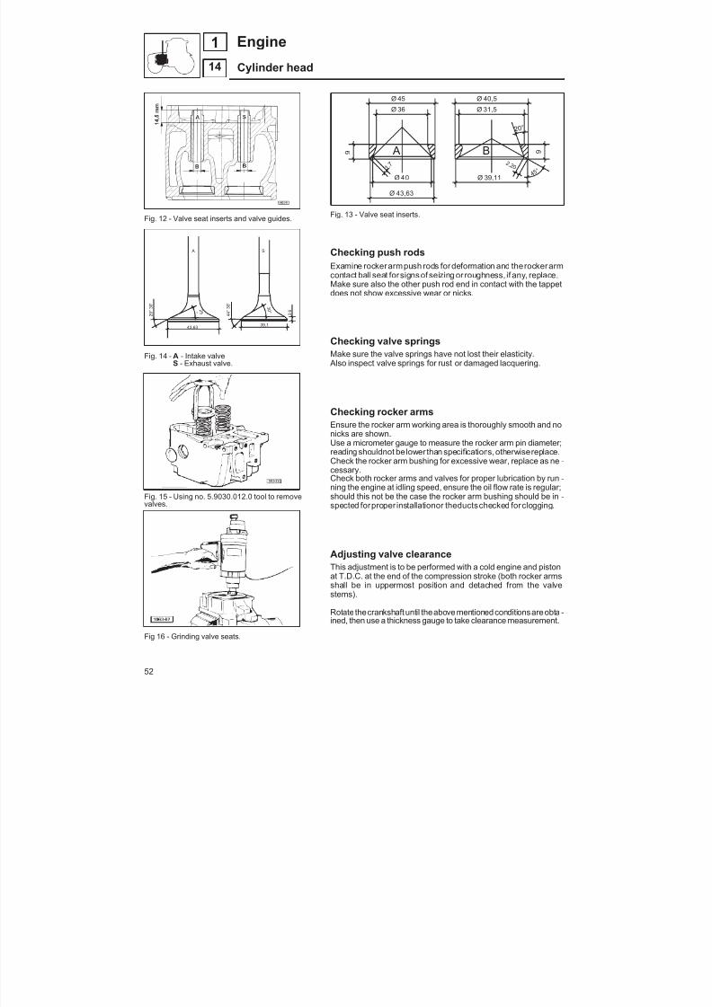
8/19/2019 Agrocompact f60 f70 f80 f90 Repair manual
http://slidepdf.com/reader/full/agrocompact-f60-f70-f80-f90-repair-manual 52/519
Fig. 12 - Valve seat inserts and valve guides.
Fig. 14 - A - Intake valve
S - Exhaust valve.
Fig. 15 - Using no. 5.9030.012.0 tool to removevalves.
Fig 16 - Grinding valve seats.
Fig. 13 - Valve seat inserts.
Checking push rodsExamine rockerarmpush rods fordeformation and therockerarmcontact ball seat forsigns of seizing or roughness, if any, replace.Make sure also the other push rod end in contact with the tappetdoes not show excessive wear or nicks.
Checking valve springsMake sure the valve springs have not lost their elasticity.
Also inspect valve springs for rust or damaged lacquering.
Checking rocker armsEnsure the rocker arm working area is thoroughly smooth and nonicks are shown.Use a micrometer gauge to measure the rocker arm pin diameter;reading shouldnot be lower than specifications, otherwisereplace.Check the rocker arm bushing for excessive wear, replace as ne -cessary.Check both rocker arms and valves for proper lubrication by run -
ning the engine at idling speed, ensure the oil flow rate is regular;should this not be the case the rocker arm bushing should be in -spected forproper installationor theductschecked forclogging.
Adjusting valve clearanceThis adjustment is to be performed with a cold engine and pistonat T.D.C. at the end of the compression stroke (both rocker armsshall be in uppermost position and detached from the valvestems).
Rotate thecrankshaftuntil theabove mentioned conditionsareobta -ined, then use a thickness gauge to take clearance measurement.
A
Ø 43,63
Ø 40
Ø 45
Ø 36
9 B 1 , 7
4 5 °
2 0 °
2 ,2 0
Ø 39,11
Ø 40,5
Ø 31,5
9
3 0 °
3 . 6
39,1
4 4 ° 3 0 '
S A
43,63
2 9 ° 3 0 '
2 5 °
52
14
1 Engine
Cylinder head
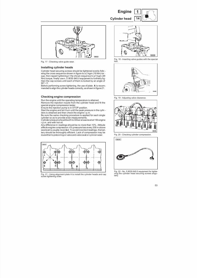
8/19/2019 Agrocompact f60 f70 f80 f90 Repair manual
http://slidepdf.com/reader/full/agrocompact-f60-f70-f80-f90-repair-manual 53/519
Fig. 17 - Checking valve guide wear.
Installing cylinder headsCylinder head securing screws should be tightened evenly follo -wing the cross sequence shown in figure to a 2 kgm (19 Nm) tor -que, then repeat tightening in the shown sequence to a 5 kgm (49Nm) torque, finally use n. 5.9030.640.0 equipment to furtherly tig -hten the cap screws until each of them is locked by an angle of 90°÷ 3’.Before performing screw tightening, the use of plate A is recom -mended toalign thecylinderheads correctly, as shownin figure21.
Checking engine compression
Run the engine until the operating temperature is attained.Remove the injection nozzle from the cylinder head and fit thespecial engine compression tester.Ensure the injection pump is in STOP position.Start the engine and let it turn until the peak pressure in the cylin -ders is obtained and then check the engine r.p.m.Be sure the same checking procedure is applied for each singlecylinder so as to provide even measurements.Cylinderpressure shouldbe25 to30bar at sea level at150 enginer.p.m. and with hot oil. Any difference in readings should be no more than 10%. Altitudeaffects engine compression:4% pressure loss every 300 m abovesea level is usually recorded. To avoid incorrect readings, thebat -tery should be thoroughly efficient. Lack of compression may bedueeither to pistonring or valve and valve seat or cylinder wear.
Fig. 21 - Using alignment plate A to install the cylinder heads and capscrew tightening order.
Fig. 18 - Inserting valve guides with the specialtool.
Fig. 19 - Adjusting valve clearance.
Fig. 20 - Checking cylinder compression.
Fig. 22 - No. 5.9030.640.0 equipment for tighte-ning the cylinder head securing screws angu-larly.
53
14
1Engine
Cylinder head

8/19/2019 Agrocompact f60 f70 f80 f90 Repair manual
http://slidepdf.com/reader/full/agrocompact-f60-f70-f80-f90-repair-manual 54/519
Fig. 1 - Oil pump assembly cross-section.
Fig. 2 - Oil radiator, oil filter and oil pan.
Oil pumpEach time the oil pump is removed or installed, ensure the gearscanrotate freelyand there is noevidenceof tool spallingor wear.
Otherwise the whole pump assembly must be replaced.
To perform a complete oli pump efficiency test insert an oil flowrate meter along with an oil pressure gauge between cylinder block and oil filter. Ensure readings correspond to specificationson page 22.
Checking pressure relief valveUsing the special fitting connect the valve to no. 5.9030.520.4equipment and make sure thevalve calibratingpressure is 3.5 to4.5 bar.If this is not the case the valve should be replaced.
Warning: whenever the oil pan is removed, ensure the prefilter wire mesh located under the oil rose pipe is thoroughly clean.Engine oil pressure can also be checked on the special dashbo -ard-mounted indicator.
Engine oil level shouldneverbe belowtheminimum level notchondipstick.
54
15
1 Engine
Lubrication system

8/19/2019 Agrocompact f60 f70 f80 f90 Repair manual
http://slidepdf.com/reader/full/agrocompact-f60-f70-f80-f90-repair-manual 55/519
Fitting shims between engine oil pan and frontsupportBetween engine oil pan C and front support A it is required thatshims be fitted so that a 0.1 mm alignment with the engine blockplane may be obtained.
Mount theoilpan onto engineblock paying particular attention therear planes are thoroughly aligned (engine flywheel side).
With no. 5.9030.272.0 centesimal gauge and no. 5.9030.433.0 gau -gebase measure thedifferenceindimensionbetween oilpan C frontplane and engine block plane B. This difference in reading shouldbe 0.35 to 0.95 mm (make sure the oil pan plane always recessesfrom engine block plane).
Install the front support placing a number of shims which permitsboth planes to be aligned within a ± 0.1 mm allowance.
WARNING: Reading and shimming should be performed both onthe front right-hand and the front left-hand side of the oil pan asshown in figure.
Fig. 3 - Measuring the difference in dimensionbetween oil pan and engine block planes.
Fig. 4 - Positions at which to measure the difference in height between the front face of the sump pan and the engine block.
55
15
1Engine
Lubrication system
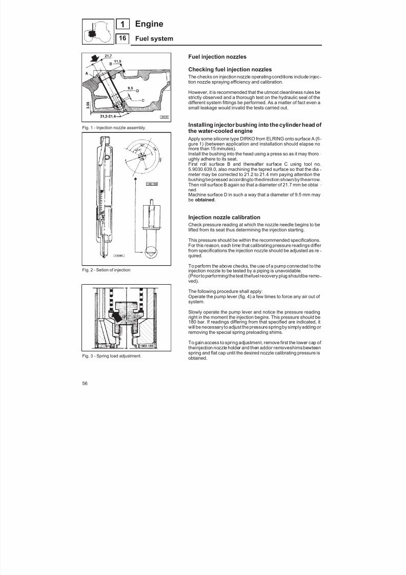
8/19/2019 Agrocompact f60 f70 f80 f90 Repair manual
http://slidepdf.com/reader/full/agrocompact-f60-f70-f80-f90-repair-manual 56/519
Fig. 1 - Injection nozzle assembly.
Fig. 2 - Setion of injection
Fig. 3 - Spring load adjustment.
Fuel injection nozzles
Checking fuel injection nozzlesThe checks on injectionnozzle operatingconditions include injec -tion nozzle spraying efficiency and calibration.
However, it is recommended that the utmost cleanliness rules bestrictly observed and a thorough test on the hydraulic seal of thedifferent system fittings be performed. As a matter of fact even asmall leakage would invalid the tests carried out.
Installing injector bushing into the cylinder head of the water-cooled engine
Apply some silicone type DIRKO from ELRING onto surface A (fi -gure 1) (between application and installation should elapse nomore than 15 minutes).Install the bushing into the head using a press so as it may thoro -ughly adhere to its seat.First roll surface B and thereafter surface C using tool no.5.9030.639.0, also machining the tapred surface so that the dia -meter may be corrected to 21.2 to 21.4 mm paying attention thebushingbepressed accordingto thedirection shown by thearrow.Then roll surface B again so that a diameter of 21.7 mm be obtai -ned.Machine surface D in such a way that a diameter of 9.5 mm maybe obtained .
Injection nozzle calibrationCheck pressure reading at which the nozzle needle begins to belifted from its seat thus determining the injection starting.
This pressure should be within the recommended specifications.For this reason, each time that calibrating pressure readings differ from specifications the injection nozzle should be adjusted as re -quired.
To perform the above checks, the use of a pump connected to theinjection nozzle to be tested by a piping is unavoidable.(Prior to performing the test thefuel recovery plug shouldbe remo -ved).
The following procedure shall apply:Operate the pump lever (fig. 4) a few times to force any air out of system.
Slowly operate the pump lever and notice the pressure readingright in the moment the injection begins. This pressure should be180 bar. If readings differing from that specified are indicated, itwill be necessary to adjust thepressure springby simplyadding or removing the special spring preloading shims.
To gain access to spring adjustment, remove first the lower cap of
theinjection nozzle holder and then addor removeshimsbewteenspring and flat cap until the desired nozzle calibrating pressure isobtained.
56
16
1 Engine
Fuel system
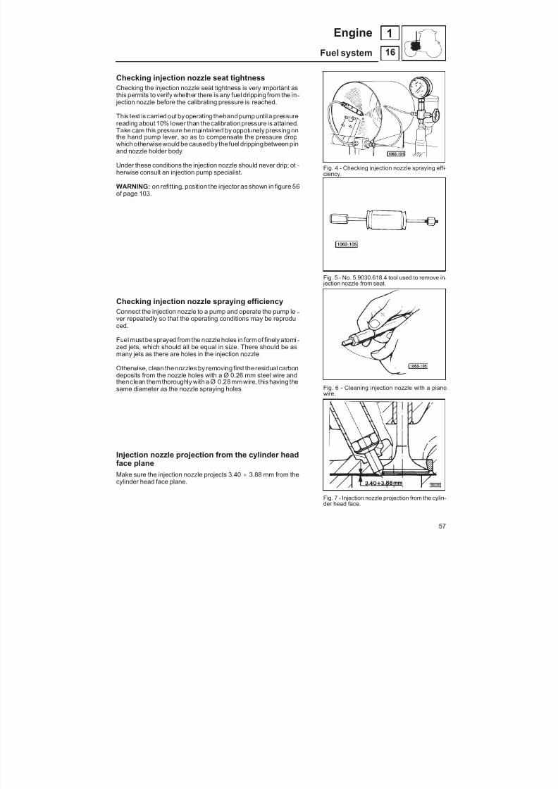
8/19/2019 Agrocompact f60 f70 f80 f90 Repair manual
http://slidepdf.com/reader/full/agrocompact-f60-f70-f80-f90-repair-manual 57/519
Checking injection nozzle seat tightnessChecking the injection nozzle seat tightness is very important as
this permits to verify whether there is any fuel dripping from the in - jection nozzle before the calibrating pressure is reached.
This test is carried out by operating thehandpumpuntil a pressurereading about 10% lower than the calibrationpressure is attained.Take care this pressure be maintained by oppotunely pressing onthe hand pump lever, so as to compensate the pressure dropwhich otherwisewould be causedby thefuel drippingbetween pinand nozzle holder body.
Under these conditions the injection nozzle should never drip; ot -herwise consult an injection pump specialist.
WARNING: on refitting, position the injector as shown in figure 56of page 103.
Checking injection nozzle spraying efficiencyConnect the injection nozzle to a pump and operate the pump le -ver repeatedly so that the operating conditions may be reprodu -ced.
Fuel must besprayed fromthe nozzle holes in form of finely atomi -zed jets, which should all be equal in size. There should be asmany jets as there are holes in the injection nozzle.
Otherwise, clean thenozzles by removing first theresidual carbondeposits from the nozzle holes with a Ø 0.26 mm steel wire and
thenclean themthoroughly with a Ø 0.28mmwire, this having thesame diameter as the nozzle spraying holes.
Injection nozzle projection from the cylinder headface planeMake sure the injection nozzle projects 3.40 3.88 mm from thecylinder head face plane.
Fig. 4 - Checking injection nozzle spraying effi -ciency.
Fig. 5 - No. 5.9030.618.4 tool used to remove in - jection nozzle from seat.
Fig. 6 - Cleaning injection nozzle with a pianowire.
Fig. 7 - Injection nozzle projection from the cylin-der head face.
57
16
1Engine
Fuel system

8/19/2019 Agrocompact f60 f70 f80 f90 Repair manual
http://slidepdf.com/reader/full/agrocompact-f60-f70-f80-f90-repair-manual 58/519
MECHANICAL-TYPE ENGINE GOVERNOR
Fig. 8 - Engine governor assembly longitudinal sections.
Fig.9 - Enginegovernor transmission assembly.
Mechanical-type engine governor The engine injection pump governor assembly is a very advanceddesign both for specific operating features and easy servicing.The engine governor has been developed as a complete unit onwhich either repairs or adjustments can be performed after remo -val from engine.Besides facilitating operations, also it offers the advantage of be -ing swiftly replaced or temporarily interchanged with a unit of same type and specifications, thus preventing the machine fromlying idle in the event of mechanical interventions on it.The following equipment is also provided with the governor as -sembly:
Automatic extra fuel supplyWhenever the engine is turned off, extra fuel is automatically sup -plied to the combustion chamber by this unit; this ensures aprompt engine starting response. (To be sure this automaticsupply function is not prevented in very cold weather, we recom -mend releasing theengine fuel shut-off control - STOP - immedia -tely after the engine has been stopped).
Engine fuel shut-off This control permits the engine to be stopped effortlessly, as it di -rectly operates the pump control rod and no connection to the go -vernor assembly is provided.
Anti-hunting
This device limits the engine speed variation when this turns atfast idling speed.
58
16
1 Engine
Fuel system

8/19/2019 Agrocompact f60 f70 f80 f90 Repair manual
http://slidepdf.com/reader/full/agrocompact-f60-f70-f80-f90-repair-manual 59/519
Fig. 10 - Engine governor assembly cross-section.
Mounting governor weights (Fig. 11) Apply Loctite601to the crankshaft surface A in contactwithsupportB , then fit the support to the crankshaft, positioning the twopieces toallow fitting of dowel F .Fit the weights C and E to the support by means of plates D insertedin the groove of the sliding sleeve.Openweight C against the stop thereby holding the weight whoseplate rests on thecoupling andreleasing theother one, then movethe coupling against the locked plate. Be sure the dimension rea -ding is 61 0,1 mm as shown in Fig. 11, otherwise add or removeshims (ref. code 2.1589.160.0and2.1589.161.0) to/fromthepositionindicated by the arrow.
Assembly of the governor unit (fig. 13)Lower casingFit the internal and external STOP control levers and fit the plateand stop screws. Fit bearing A in the casing and fit levers B and Cwith complete unit.WARNING: before fitting lever C, check that 20 mm section indi -cated in the figure is completely free of burrs or indents. Insert theshaft complete with the governor weights, securing it to the bea-ring with the nut. Fit bearing D and thesliding sleeveand fit eccen -tricscrew E to the casingso that the chasing onthe headis positio -ned at the top.e
Fig. 11 - Installing weights on thegovernorshaft.
Before assembly, apply Loctite 601 to the outer surfaces of bush D , tube E and fitting B.Before assembly, apply Loctite 601 to the outer surfaces of bush G and bush H .Before tightening nut C, coat the thread with Loctite 270.Before assembly, apply Loctite 270 to thread of the control lever retaining bolt F .
Fig. 12 - LOCTITE application points.
59
16
1Engine
Fuel system
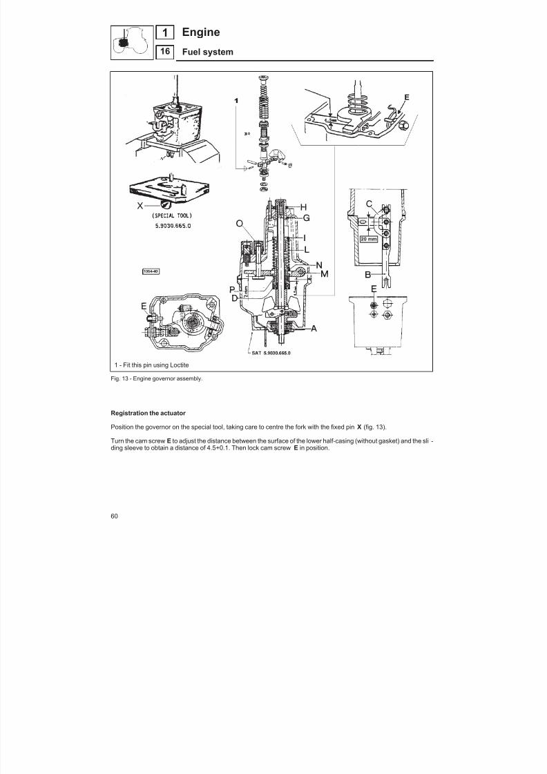
8/19/2019 Agrocompact f60 f70 f80 f90 Repair manual
http://slidepdf.com/reader/full/agrocompact-f60-f70-f80-f90-repair-manual 60/519
1 - Fit this pin using Loctite
Fig. 13 - Engine governor assembly.
Registration the actuator
Position the governor on the special tool, taking care to centre the fork with the fixed pin X (fig. 13).
Turn the cam screw E to adjust the distance between the surface of the lower half-casing (without gasket) and the sli -ding sleeve to obtain a distance of 4.5+0.1. Then lock cam screw E in position.
60
16
1 Engine
Fuel system
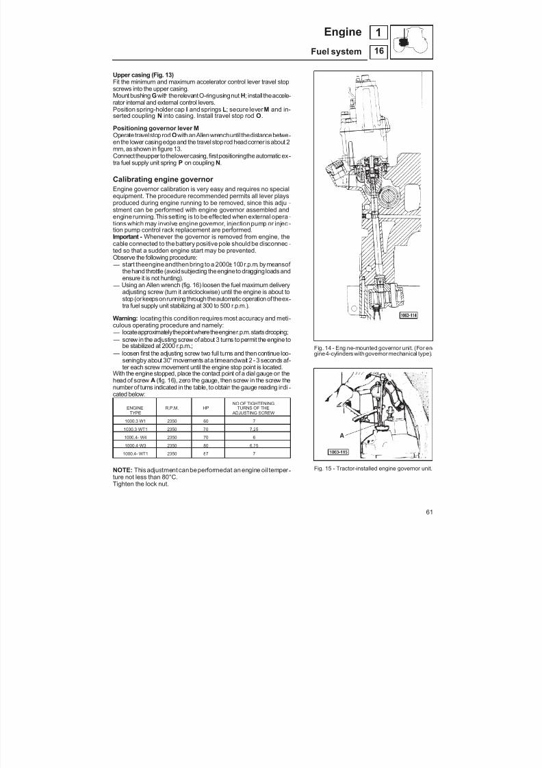
8/19/2019 Agrocompact f60 f70 f80 f90 Repair manual
http://slidepdf.com/reader/full/agrocompact-f60-f70-f80-f90-repair-manual 61/519
Upper casing (Fig. 13)Fit the minimum and maximum accelerator control lever travel stopscrews into the upper casing.Mount bushing G with therelevantO-ringusingnut H; install theaccele -rator internal and external control levers.Position spring-holder cap I and springs L; secure lever M and in-serted coupling N into casing. Install travel stop rod O .
Positioning governor lever MOperate travelstop rod O with anAllenwrenchuntil thedistancebetwe -enthe lower casingedgeand the travel stoprod headcorner is about 2mm, as shown in figure 13.Connecttheupper tothelowercasing,firstpositioningtheautomatic ex -tra fuel supply unit spring P on coupling N.
Calibrating engine governor Engine governor calibration is very easy and requires no specialequipment. The procedure recommended permits all lever playsproduced during engine running to be removed, since this adju -stment can be performed with engine governor assembled andengine running.This setting is to be effected when external opera -tions which may involve engine governor, injection pump or injec -tion pump control rack replacement are performed.Important - Whenever the governor is removed from engine, thecable connected to the battery positive pole should be disconnec -ted so that a sudden engine start may be prevented.Observe the following procedure: — start theengineandthenbring to a 2000± 100r.p.m. by meansof
thehand throttle (avoidsubjecting theengineto draggingloads and
ensure it is not hunting). — Using an Allen wrench (fig. 16) loosen the fuel maximum deliveryadjusting screw (turn it anticlockwise) until the engine is about tostop (orkeepsonrunning throughtheautomatic operation of theex -tra fuel supply unit stabilizing at 300 to 500 r.p.m.).
Warning: locating this condition requires most accuracy and meti -culous operating procedure and namely: — locateapproximatelythepointwheretheenginer.p.m.startsdrooping; — screw in the adjusting screw ofabout 3 turns to permit the engine to
be stabilized at 2000 r.p.m.; — loosen first the adjusting screw two full turns and thencontinue loo -
seningby about 30° movements ata timeandwait 2 - 3 seconds af -ter each screw movement until the engine stop point is located.
With the enginestopped, place the contact point of a dial gauge on thehead of screw A (fig. 16), zero the gauge, then screw in the screw thenumber of turns indicated in the table, to obtain the gauge reading indi -cated below:
NO OF TIGHTENINGENGINE R.P.M. HP TURNS OF THE
TYPE ADJUSTING SCREW
1000.3 W1 2350 60 7
1000.3-WT1 2350 70 7,25
1000.4- W4 2350 70 6
1000.4-W3 2350 80 6,75
1000.4- WT1 2350 87 7
NOTE: This adjustment canbeperformedat an engine oil temper -ture not less than 80°C.Tighten the lock nut.
Fig. 14 - Engine-mounted governor unit. (For en -gine4-cylinders withgovernor mechanical type).
Fig. 15 - Tractor-installed engine governor unit.
61
16
1Engine
Fuel system

8/19/2019 Agrocompact f60 f70 f80 f90 Repair manual
http://slidepdf.com/reader/full/agrocompact-f60-f70-f80-f90-repair-manual 62/519
FITTING AND ADJUSTMENT OF THE EXTERNAL CONTROLS OF THE MECHANICALGOVERNORAccelerator pedal (fig. 16). Attach the throttle cable A to bracket C andthen to lever D , thenfit spring P . Adjust thepositionof screw G toobtaina pe -dal travel of 75 mm as shown in figure 16 (corresponding to an angle of approximately 32°) and secure in position withlocknut Q .
Hand throttle Attach the throttle cable B to bracket E by tightening screw N and positioning the locknuts O and thenattach the cable to le -ver V.
Connection of the accelerator pedal and hand throttle cables to the governor. Attach the throttle cable to bracket H of the governor by way of screw L, and secure with locknuts I;Connect the throttle cable to bracket M of the governor. Adjust the freeplay of the throttle cable by turning the screw L (after having undone the locknuts I) so that the cable is
correctly tensioned, then re-tighten the locknuts. Attach the throttle cable S of the hand throttle to bracket T and then attach it to lever U.Then apply a force f = 5 ±0,5 to lever F and screw in self-locking nut R until the force applied is no longer capable of movingthe lever. Move the hand throttle lever to the “MAX” position and manually push lever F to the end of its travel, thenscrew in screw N until the throttle cable is fully tensioned, then tighten locknuts O .
Fig. 16 - Adjustment of the external controls of the mechanical governor.
62
16
1 Engine
Fuel system

8/19/2019 Agrocompact f60 f70 f80 f90 Repair manual
http://slidepdf.com/reader/full/agrocompact-f60-f70-f80-f90-repair-manual 63/519
Fig. 17 - Component for control accelerator pedal and manual.
63
16
1Engine
Fuel system
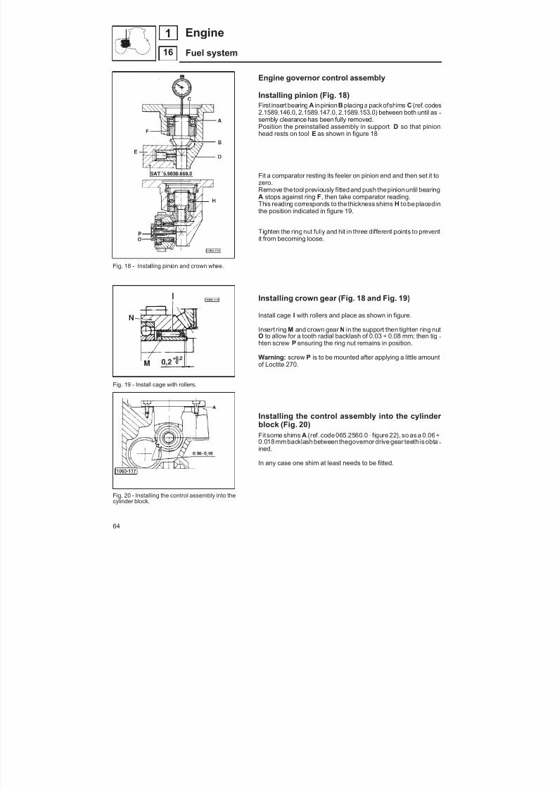
8/19/2019 Agrocompact f60 f70 f80 f90 Repair manual
http://slidepdf.com/reader/full/agrocompact-f60-f70-f80-f90-repair-manual 64/519
Fig. 18 - Installing pinion and crown whee.
Fig. 19 - Install cage with rollers.
Fig. 20 - Installing the control assembly into thecylinder block.
Engine governor control assembly
Installing pinion (Fig. 18)First insert bearing A inpinion B placing a packofshims C (ref. codes2.1589.146.0, 2.1589.147.0, 2.1589.153.0) between both until as -sembly clearance has been fully removed.Position the preinstalled assembly in support D so that pinionhead rests on tool E as shown in figure 18.
Fit a comparator resting its feeler on pinion end and then set it tozero.
Remove the tool previously fittedand push thepinionuntil bearingA stops against ring F , then take comparator reading.This reading corresponds to the thickness shims H to be placedinthe position indicated in figure 19.
Tighten the ring nut fully and hit in three different points to preventit from becoming loose.
Installing crown gear (Fig. 18 and Fig. 19)
Install cage I with rollers and place as shown in figure.
Insert ring M and crown gear N in the support then tighten ring nutO to allow for a tooth radial backlash of 0.03 ÷ 0.08 mm; then tig -hten screw P ensuring the ring nut remains in position.
Warning: screw P is to be mounted after applying a little amountof Loctite 270.
Installing the control assembly into the cylinder block (Fig. 20)Fit some shims A (ref. code065.2560.0 - figure 22), so as a 0.06÷0.018mmbacklash between thegovernor drive gear teeth is obta -ined.
In any case one shim at least needs to be fitted.
64
16
1 Engine
Fuel system
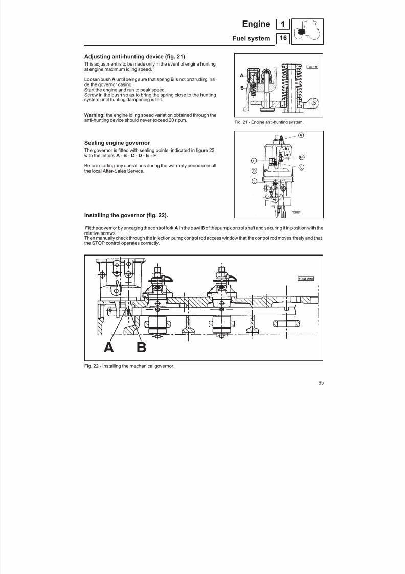
8/19/2019 Agrocompact f60 f70 f80 f90 Repair manual
http://slidepdf.com/reader/full/agrocompact-f60-f70-f80-f90-repair-manual 65/519
Adjusting anti-hunting device (fig. 21)This adjustment is to be made only in the event of engine hunting
at engine maximum idling speed.
Loosen bush A until beingsure that spring B is not protruding insi -de the governor casing.Start the engine and run to peak speed.Screw in the bush so as to bring the spring close to the huntingsystem until hunting dampening is felt.
Warning: the engine idling speed variation obtained through theanti-hunting device should never exceed 20 r.p.m.
Sealing engine governor The governor is fitted with sealing points, indicated in figure 23,with the letters A - B - C - D - E - F .
Before starting any operations during the warranty period consultthe local After-Sales Service.
Fig. 21 - Engine anti-hunting system.
Installing the governor (fig. 22).
Fit thegovernor by engagingthecontrol fork A in the pawl B of thepumpcontrol shaft and securing it in position with therelative screws.Then manually check through the injection pump control rod access window that the control rod moves freely and thatthe STOP control operates correctly.
Fig. 22 - Installing the mechanical governor.
65
16
1Engine
Fuel system
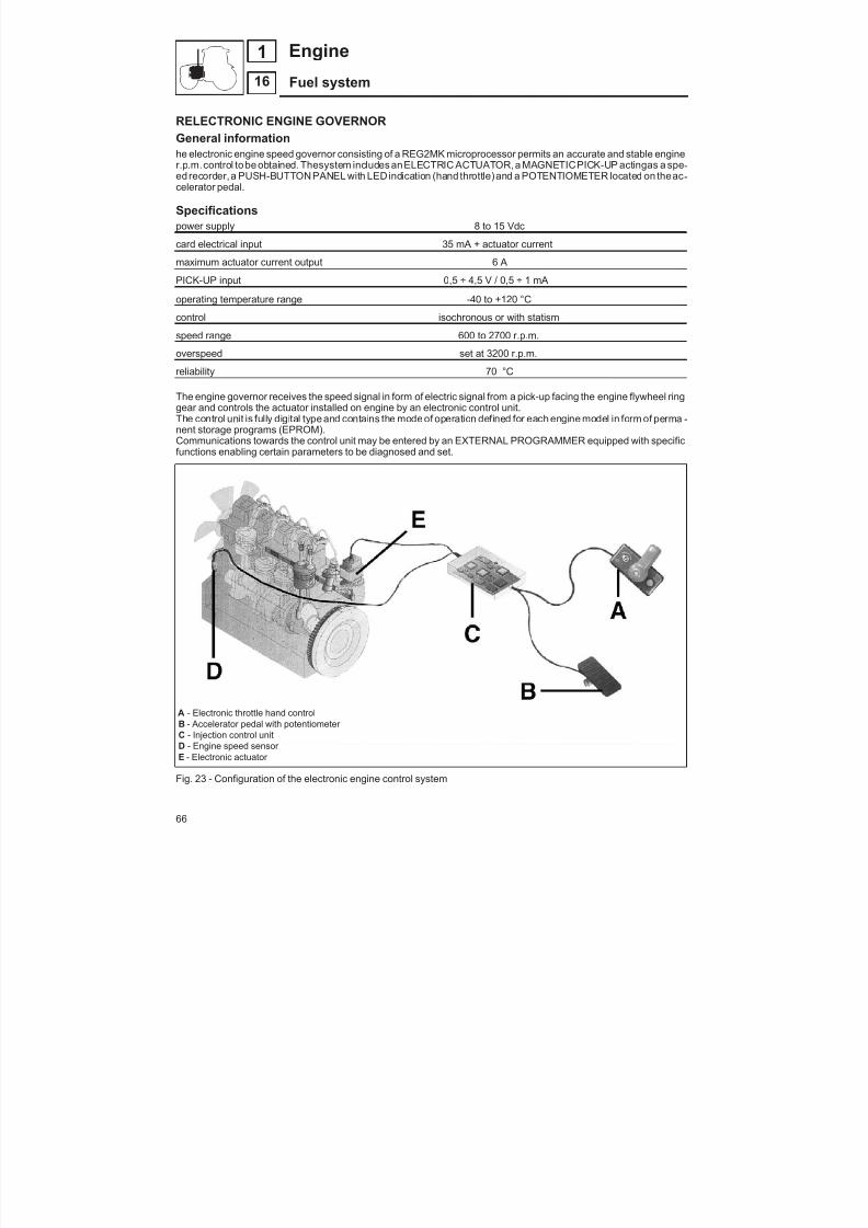
8/19/2019 Agrocompact f60 f70 f80 f90 Repair manual
http://slidepdf.com/reader/full/agrocompact-f60-f70-f80-f90-repair-manual 66/519
RELECTRONIC ENGINE GOVERNORGeneral informationhe electronic engine speed governor consisting of a REG2MK microprocessor permits an accurate and stable enginer.p.m.control to be obtained. Thesystem includes anELECTRIC ACTUATOR,a MAGNETICPICK-UP actingas a spe -ed recorder, a PUSH-BUTTON PANEL with LEDindication (hand throttle) and a POTENTIOMETER located on theac -celerator pedal.
Specificationspower supply 8 to 15 Vdc
card electrical input 35 mA + actuator current
maximum actuator current output 6 A
PICK-UP input 0,5 ÷ 4,5 V / 0,5 ÷ 1 mA
operating temperature range -40 to +120 °Ccontrol isochronous or with statism
speed range 600 to 2700 r.p.m.
overspeed set at 3200 r.p.m.
reliability 70 °C
The engine governor receives the speed signal in form of electric signal from a pick-up facing the engine flywheel ringgear and controls the actuator installed on engine by an electronic control unit.The control unit is fully digital type and contains the mode of operation defined for each engine model in form of perma -nent storage programs (EPROM).Communications towards the control unit may be entered by an EXTERNAL PROGRAMMER equipped with specificfunctions enabling certain parameters to be diagnosed and set.
A - Electronic throttle hand controlB - Accelerator pedal with potentiometer C - Injection control unitD - Engine speed sensor E - Electronic actuator
Fig. 23 - Configuration of the electronic engine control system
66
16
1 Engine
Fuel system

8/19/2019 Agrocompact f60 f70 f80 f90 Repair manual
http://slidepdf.com/reader/full/agrocompact-f60-f70-f80-f90-repair-manual 67/519

8/19/2019 Agrocompact f60 f70 f80 f90 Repair manual
http://slidepdf.com/reader/full/agrocompact-f60-f70-f80-f90-repair-manual 68/519
Installing and checking the pick-upPick-up engine 1st version
The pick-up should be installed in the following manner:Adjustment of a new pick-upScrewthe pick-up inthe 1.5pitch threadedholeM16 placedon thebelluntil contacting theringgearthentightenthelocknut. Adjustment of an operating pick-upIf the pick-up has already been operated, after screwing against the ring gear loosen by 1/2 turn and then lock so as0.65 0.75 mm gap may be obtained.
Pick-up engine 2nd version
The pick-up should be installed in the following manner:
Position the pickup in its seating and secure with retaining screw.The distance between the pickup and the pulse wheel must be 0.5 mm; check using feeler gauge 5.9030.270.0.
isochronous operation: depressing push button HOLDrigorously constant.operation with statism: if the HOLD/RESET push boperates with a r.p.m. droop of about 7% from idling to futractor on public roads.fixed-speed hand control: this helps reproduce the han
functions: — isochronous operating mode; — speed statism operating mode; — 600 2700 RPM speed adjustment; — hand throttle digital control; — dling speed under variable statism of 600 to 1500 r.p.m — speed under variable isochronous operating
mode from previous idling speed to 2500 r.p.m.; — limitation of the peak horsepower varying with the speed; — self-diagnosis of protection intervention and faults
protections: — pick-up signal loss protection; — actuator terminal short-circuit protection; — overspeed protection; — battery polarity reversal protection; — power supply loss protection; — microprocessor fault protection.
Installing componentsThe installation of the various components should be carriedout with battery disconnected.
— the positive of the key subsequently supplying power to the card is directed towards battery +.
— the card power supply in-series fuse is 7.5 A.
Note : the metal box housing the card is connected to battenegative through a card-internal connection.
68
Engine
Fuel system
1
16
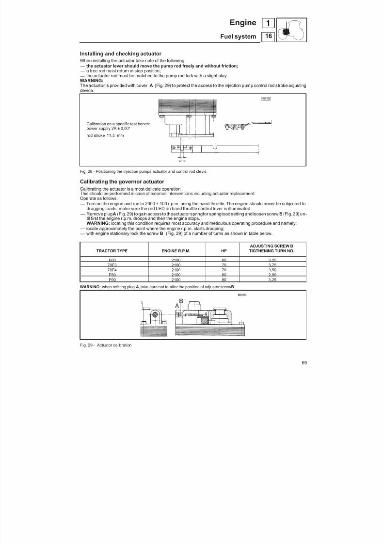
8/19/2019 Agrocompact f60 f70 f80 f90 Repair manual
http://slidepdf.com/reader/full/agrocompact-f60-f70-f80-f90-repair-manual 69/519
Installing and checking actuator When installing the actuator take note of the following:
— the actuator lever should move the pump rod freely and without friction; — a free rod must return in stop position; — the actuator rod must be matched to the pump rod fork with a slight play.WARNING:The actuator is provided with cover A (Fig. 29) to protect the access to the injection pump control rod stroke adjustingdevice.
Calibration on a specific test bench:power supply 2A ± 0,001
rod stroke 11,5 + 0,2 mm
Fig. 28 - Positioning the injection pumps actuator and control rod clevis.
Calibrating the governor actuator Calibrating the actuator is a most delicate operation.This should be performed in case of external interventions including actuator replacement.Operate as follows: — Turn on the engine and run to 2000 100 r.p.m. using the hand throttle. The engine should never be subjected to
dragging loads, make sure the red LED on hand throttle control lever is illuminated. — Remove plug A (Fig. 29) to gain access to theactuatorspringfor springload setting andloosen screw B (Fig. 29) un-
til first the engine r.p.m. droops and then the engine stops.WARNING: locating this condition requires most accuracy and meticulous operating procedure and namely:
— locate approximately the point where the engine r.p.m. starts drooping; — with engine stationary lock the screw B (Fig. 29) of a number of turns as shown in table below.
ADJUSTING SCREW BTRACTOR TYPE ENGINE R.P.M. HP TIGTHENING TURN NO.
F60 2100 60 3,2570F3 2100 70 3,7570F4 2100 70 3,50F80 2100 80 2,90F90 2100 90 3,25
WARNING: when refitting plug A, take care not to alter the position of adjuster screw B.
Fig. 29 - Actuator calibration
69
16
1Engine
Fuel system
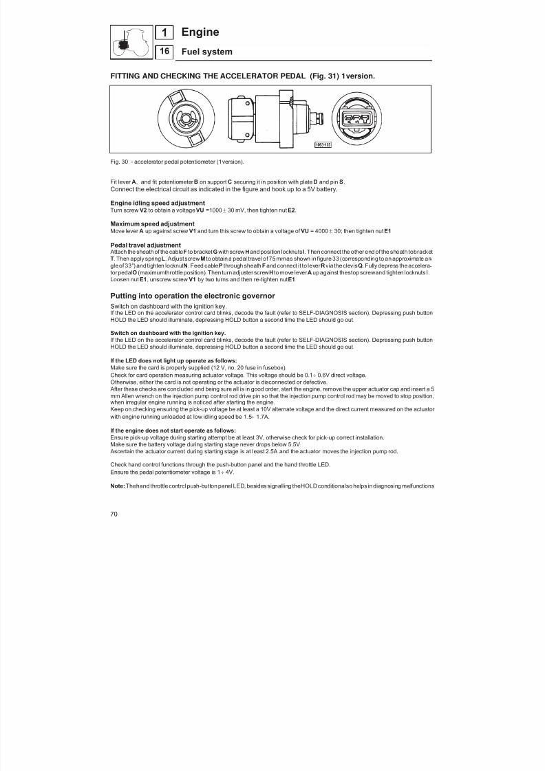
8/19/2019 Agrocompact f60 f70 f80 f90 Repair manual
http://slidepdf.com/reader/full/agrocompact-f60-f70-f80-f90-repair-manual 70/519
FITTING AND CHECKING THE ACCELERATOR PEDAL (Fig. 31) 1 st version.
Fig. 30 - accelerator pedal potentiometer (1 st version).
Fit lever A , and fit potentiometer B on support C securing it in position with plate D and pin S .Connect the electrical circuit as indicated in the figure and hook up to a 5V battery.
Engine idling speed adjustmentTurn screw V2 to obtain a voltage VU =1000 30 mV, then tighten nut E2 .
Maximum speed adjustmentMove lever A up against screw V1 and turn this screw to obtain a voltage of VU = 4000 30; then tighten nut E1
Pedal travel adjustment Attach the sheath of the cable F to bracket G withscrew H and position locknuts I. Then connect the other end of the sheath tobracketT. Then apply spring L . Adjust screw M to obtain a pedal travel of 75 mmas shown in figure 33 (corresponding to an approximate an -gleof 33°) and tighten locknut N . Feed cable P through sheath F and connect it to lever R via theclevis Q . Fully depress theaccelera -tor pedal O (maximumthrottle position).Then turnadjuster screw H to move lever A up against thestop screwand tighten locknuts I.
Loosen nut E1 , unscrew screw V1 by two turns and then re-tighten nut E1
Putting into operation the electronic governor Switch on dashboard with the ignition key.If the LED on the accelerator control card blinks, decode the fault (refer to SELF-DIAGNOSIS section). Depressing push buttonHOLD the LED should illuminate, depressing HOLD button a second time the LED should go out.
Switch on dashboard with the ignition key.If the LED on the accelerator control card blinks, decode the fault (refer to SELF-DIAGNOSIS section). Depressing push buttonHOLD the LED should illuminate, depressing HOLD button a second time the LED should go out.
If the LED does not light up operate as follows:Make sure the card is properly supplied (12 V, no. 20 fuse in fusebox).Check for card operation measuring actuator voltage. This voltage should be 0.1 0.6V direct voltage.Otherwise, either the card is not operating or the actuator is disconnected or defective. After these checks are concluded and being sure all is in good order, start the engine, remove the upper actuator cap and insert a 5mm Allen wrench on the injection pump control rod drive pin so that the injection pump control rod may be moved to stop position,when irregular engine running is noticed after starting the engine.Keep on checking ensuring the pick-up voltage be at least a 10V alternate voltage and the direct current measured on the actuator with engine running unloaded at low idling speed be 1.5 1.7A.
If the engine does not start operate as follows:Ensure pick-up voltage during starting attempt be at least 3V, otherwise check for pick-up correct installation.Make sure the battery voltage during starting stage never drops below 5.5V. Ascertain the actuator current during starting stage is at least 2.5A and the actuator moves the injection pump rod.
Check hand control functions through the push-button panel and the hand throttle LED.Ensure the pedal potentiometer voltage is 1 4V.
Note: Thehand throttle control push-button panel LED, besides signalling theHOLDconditionalso helps in diagnosing malfunctions
70
16
1 Engine
Fuel system
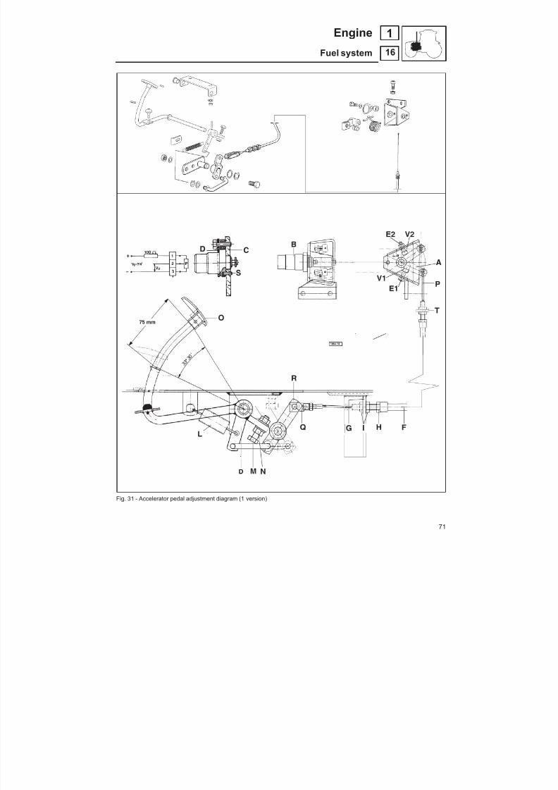
8/19/2019 Agrocompact f60 f70 f80 f90 Repair manual
http://slidepdf.com/reader/full/agrocompact-f60-f70-f80-f90-repair-manual 71/519
8/19/2019 Agrocompact f60 f70 f80 f90 Repair manual
http://slidepdf.com/reader/full/agrocompact-f60-f70-f80-f90-repair-manual 72/519
FITTING AND CHECKING THE ACCELERATOR PEDAL (Fig. 32) 2 nd version.
Fit lever A , and fit potentiometer B on support C , securing it in position with the screws D .
Connect the electrical circuit as indicated in the figure and connect a 5V battery.
Idle speed adjustmentTurn screw V2 to obtain a voltage U1 10 = 0.5V , then tighten locknut E2 .
Maximum speed adjustmentBring lever A up against screw V1 and turn the screw to obtain a voltage U 90 = 4.5 V , then tighten locknut E1 .
Pedal travel adjustment Attach the outer sheath of the cable F to bracket G withboltH and fit the locknutsI. Then attachthe opposite end ofthe outer sheath tobracket T . Fit spring L . Adjust the position of screw M to obtain the pedal travel indicated in Fig. 32 (corresponding to an angle of ap -prox. 33*) andtighten locknut N. Feed thecable P through sheath F and attachit to lever R via clevis Q . Fully depress theaccelerator pedal O (maximum throttle position), then turn adjuster screw H to bring lever A up against the stop screw and tighten locknuts I.Back off the locknut E1 , unscrew the screw V1 by two full turns, and then re-tighten the locknut E1 .
72
16
1 Engine
Fuel system

8/19/2019 Agrocompact f60 f70 f80 f90 Repair manual
http://slidepdf.com/reader/full/agrocompact-f60-f70-f80-f90-repair-manual 73/519
Fig. 32 - Accelerator pedal adjustment diagram (2 nd version).
73
16
1Engine
Fuel system

8/19/2019 Agrocompact f60 f70 f80 f90 Repair manual
http://slidepdf.com/reader/full/agrocompact-f60-f70-f80-f90-repair-manual 74/519
Fig. 33 - Pick-up.
DIAGNOSING MALFUNCTIONS (1 st version)
Operating as follows the self-diagnosingsystem is in a position to diagnose any failures and warn the operator throughthe led located on the hand throttle control push-button panel.
FAILURE NO. OF LED BLINKS LIKELY CAUSE
pick-up 4 pick-up failure, pick-up disconnected
actuator 2 actuator short-circuited, actuator disconnected
potentiometer pedalaccelerator 3 potentiometer failure, potentiometer disconnected
overspeed 1 attuatore locked, injection pump locked
storage 5 parameter storage not programmed or defective
WARNING:Should any failure be found take the number of LED blinks from the control push-button;This LEDblink number will permit therepairingtechnician to readily perform replacement through thecorrect spare partneeded.
74
16
1 Engine
Fuel system
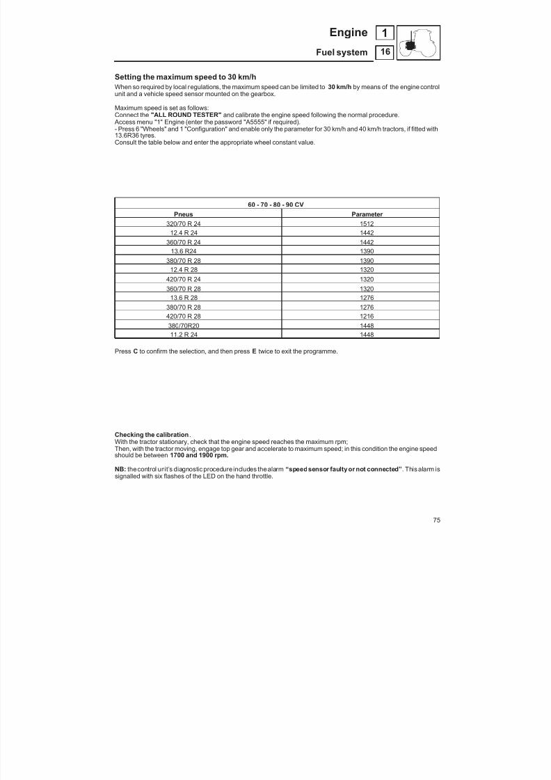
8/19/2019 Agrocompact f60 f70 f80 f90 Repair manual
http://slidepdf.com/reader/full/agrocompact-f60-f70-f80-f90-repair-manual 75/519
Setting the maximum speed to 30 km/hWhen so required by local regulations, the maximum speed can be limited to 30 km/h by means of the engine control
unit and a vehicle speed sensor mounted on the gearbox.
Maximum speed is set as follows:Connect the "ALL ROUND TESTER" and calibrate the engine speed following the normal procedure. Access menu "1" Engine (enter the password "A5555" if required).- Press 6 "Wheels" and 1 "Configuration" and enable only the parameter for 30 km/h and 40 km/h tractors, if fitted with13.6R36 tyres.Consult the table below and enter the appropriate wheel constant value.
60 - 70 - 80 - 90 CVPneus Parameter
320/70 R 24 151212.4 R 24 1442
360/70 R 24 144213.6 R24 1390
380/70 R 28 139012.4 R 28 1320
420/70 R 24 1320360/70 R 28 1320
13.6 R 28 1276380/70 R 28 1276420/70 R 28 1216380/70R20 144811.2 R 24 1448
Press C to confirm the selection, and then press E twice to exit the programme.
Checking the calibration .With the tractor stationary, check that the engine speed reaches the maximum rpm;Then, with the tractor moving, engage top gear and accelerate to maximum speed; in this condition the engine speedshould be between 1700 and 1900 rpm.
NB: thecontrol unit’s diagnostic procedure includes thealarm “speedsensor faulty or not connected” . This alarm issignalled with six flashes of the LED on the hand throttle.
75
16
1Engine
Fuel system

8/19/2019 Agrocompact f60 f70 f80 f90 Repair manual
http://slidepdf.com/reader/full/agrocompact-f60-f70-f80-f90-repair-manual 76/519
Fuel injection pumps
The single-cylinder fuel injection pumps are equipped with a constant-pressure backflow valve (short G.D.V. valve).
The plunger load is evenly distributed over the whole camshaft, since an equal-distance distribution is provided.
TheG.D.V. valvekeepspressure insidetheinjection pipes to a high levelduringtheintermediate pump delivery phases.
This ensures engine smooth running even at lowoperating speed, higher engineperformanceas well as more favoura -ble torque curves, besides suppressing any nozzle dribbles resulting in unburnt gas, poor injection nozzle efficiencyand engine detonation.
Fig. 1 - Injection pump control assembly.
Fig. 2 - Mounting positions of the injection pumpcontrol bar guide supports.
Injection pump control systemThe injectionpumps aresimultaneouslycontrolled by a blank she -et steel bar which besides ensuring the required stiffness haspar -ticular lightweight properties to prevent excessive friction andinertia under operating conditions.This bar controls the injection pumps operating through speciallyarranged slots and is connected to the engine governor by a rat -chet.The injection pump control bar is guided by a couple of block-mo -unted supports provided with slide rings.
Installing injection pump control bar guide sup -ports (Fig. 2)Install supports A with related O-rings, rollers and lockpins usingscrews B into the engine block. Insert the injection pump controlbar C into the supports and tighten screws B and ensure that thebar is free to slide inside the support. (The two supports equippedwith sliding rollers should be placed at both bar ends).Warning - When the injectionpumps areremoved operate theen -gine shutoff control (STOP) so as to bring the rack rod dog back totheinjection pump centre line. This permits it to be passed through
the special aperture in the engine block.Check is made visually through the sight windows in the engineblock.
76
16
1 Engine
Fuel system

8/19/2019 Agrocompact f60 f70 f80 f90 Repair manual
http://slidepdf.com/reader/full/agrocompact-f60-f70-f80-f90-repair-manual 77/519
Engine timing
Valve timing
This should be carried out before injection pump calibration.
Raise the first cylinder piston to upper position; remove the rocker arm support, remove intake valve spring and drop valve onto pi -ston head then insert a snap ring into the valve stem.
Fastenno. 5.9030.616.4equipment on pistonhead as shown in fi-gure 4 (the comparator indicating 25 mm strokereading shouldbeplaced on the engine valve).
After raising piston to T.D.C. position set to zero the comparator fi -
xed to the valve stem. When the concerned cam rest race hasbeen located also reset thecomparator applied to the intakevalvetappet head.
Turn the crankshaft clockwise until a 17.27 mm piston stroke hasbeen completed. Then rotate the camshaft until a 3.93 0.1 mmintake cam lift is obtained.
Fit the timinggear and bring the timinggear markedtooth into con -tact with both idler gear marked teeth. Press on the gear anticloc -kwise when tightening thesecuring screws until any backlashbet -ween teeth is taken up.
Take the equipment and proceed with the injection pump settingoperations.
Fig. 6 - Timing gear reference marks for engine timing
Fig. 3 - No. 5.9030.616.4 engine timing equip -ment.
Fig. 4 - Equipmentmountingposition for1stcylin -der timing.
Fig. 5 - Injection pump
77
16
1Engine
Fuel system

8/19/2019 Agrocompact f60 f70 f80 f90 Repair manual
http://slidepdf.com/reader/full/agrocompact-f60-f70-f80-f90-repair-manual 78/519
Fig. 7 - No. 5.9030.617.4 /10 injection pump ti -ming equipment.
Fig. 8 - Resetting no. 5.9030.617.4 /10 compara -tor-equipped tool.
Fig. 9 - Mounting position of the no.5.9030.617.4/10equipment fitted withcomparator.
Injection pump calibration (BOSCH injectionpump equipped with a lock pin for the control rod)
After valve timing has been successfully concludedundertake thiscalibration by using no. 5.9030.617.4/10 equipment in addition tothe equipment already positioned on the first cylinder and excep -ting the comparator on the valve tappet rod.
To each shim pack add a pack of shims equal to the value stam -ped on the pumps. (example: +2 must be added a thickness of 0,2mm).
Injection pump calibration is to determine a 80.4 mm dimension
between the pumps-to-block fixing surface and the correspondingcam races, considering the position they find when the injection isbeing started; (Fig.10).
Rotate the crankshaft to move the 1st cylinder piston into T.D.C.position (compression stroke end, valves closed) and set to zerothe comparator attached to the valve stem; the same procedureas described in valve timing section shall apply.
Rotate the shaft in a counter-clockwise direction until a reading of 2.92mmis shown on the dial gauge; this value corresponds to a ti -ming advance of 16.
Correct positioning takes place when through anticlockwise rota -tion either the 2.92 mm set point is exceeded, soon after comingback to such a dimension through clockwise crankshaft rotationso that any clearances may be taken up.
Fit the special no. 5.9030.617.4 comparator. To reset the compa -rator rest the comparator measuring roll onto a flat surface.
Insert the tool into the first injection pump seat and take measure -ment reading from the comparator dial to align the bearing facewith the engine block. This reading corresponds to shim pack X.
To each pack of shims X add a number of shims Y being equal tothedimension stamped on injectionpump flange, so as to obtain atotal shim packing ( X + Y) to be put between injection pump andengine block, this permitting a 80.4 mm standard dimension to bedetermined.
Repeat this operation for each injection pump, fitting tool5.9030.616.4 to the corresponding cylinder.
Warning - Install the injection pump after applying some Silastik
738 silicone between shims, engine block and injection pump.
78
16
1 Engine
Fuel system
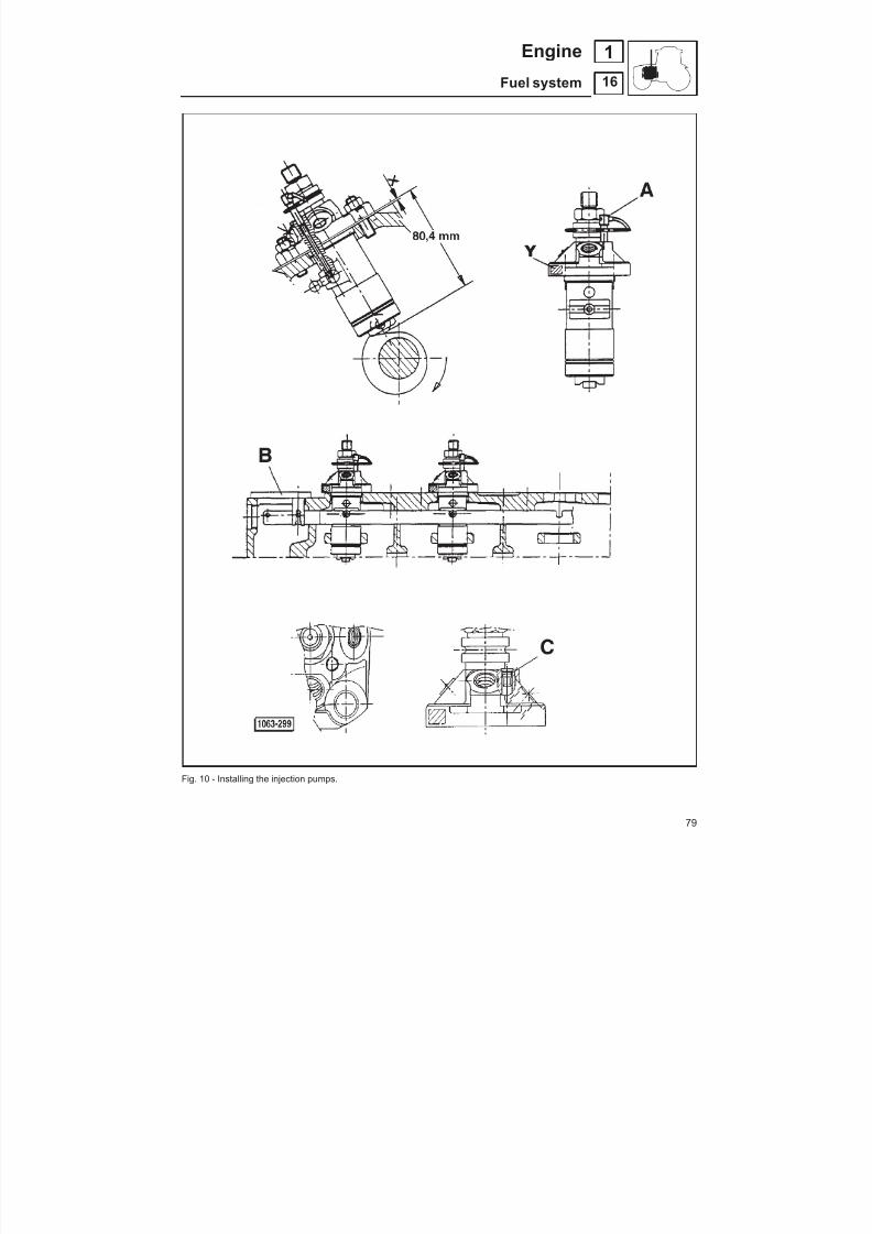
8/19/2019 Agrocompact f60 f70 f80 f90 Repair manual
http://slidepdf.com/reader/full/agrocompact-f60-f70-f80-f90-repair-manual 79/519
Fig. 10 - Installing the injection pumps.
79
16
1Engine
Fuel system
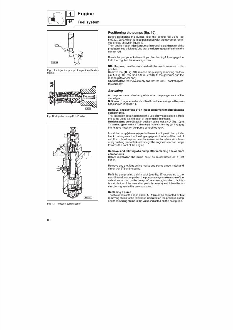
8/19/2019 Agrocompact f60 f70 f80 f90 Repair manual
http://slidepdf.com/reader/full/agrocompact-f60-f70-f80-f90-repair-manual 80/519
Fig. 11 - Injection pump plunger identificationmarks.
Fig. 12 - Injection pump G.D.V. valve.
Fig. 13 - Injection pump section
Positioning the pumps (fig. 10).Before positioning the pumps, lock the control rod using tool
5.9030.728.0, which is to be positioned with the governor remo -ved and as shown in figure 10.Then position each injection pump (interposing a shim pack of thepredetermined thickness), so that the dog engages the fork in thecontrol rod.
Rotate the pump clockwise until you feel the dog fully engage thefork, then tighten the retaining screw.
NB: Thepump must be positioned with the injectioncams in b.d.c.position.Remove tool ( B Fig. 10), release the pump by removing the lockpin A (Fig. 10 - tool SAT 5.9030.728.0); fit the governor and therear plug (flywheel end).Check that the rod moves freely and that the STOP control opera -tes correctly.
Servicing All the pumps are interchangeable as all the plungers are of thesame type.N.B : new plungers can be identified from the markings in the posi -tions shown in figure 11.
Removal and refitting of an injection pump without replacingcomponents.This operation does not require the use of any special tools. Refit
the pump using a shim pack of the original thickness.Hold the pump control rack in position using lock pin A (fig. 10) to.Todo this, operate the STOP control lever so that the pin engagesthe relative notch on the pump control rod rack.
Install the pump (also equippedwith a rack lock pin) in the cylinder block, making sure that the dog engages in the fork of the controlrod; then rotatethe pumpin a clockwisedirectionwhilst simultane -ouslypushing thecontrol rodthrough theengine inspection flangetowards the front of the engine.
Removal and refitting of a pump after replacing one or morecomponentsBefore installation the pump must be re-calibrated on a test
bench.
Remove any previous timing marks and stamp a new notch anddimension ( Y) on the pump.
Refit the pump using a shim pack (see fig. 17) according to thenew dimension stamped on the pump (always make a note of theold value stamped on the pump before erasure, in order to facilita -te calculation of the new shim pack thickness) and follow the in -structions given in the previous point.
Replacing a pumpThe thickness of the shim pack ( X + Y) must be corrected by firstremoving shims to the thickness indicated on the previous pumpand then adding shims to the value indicated on the new pump.
80
16
1 Engine
Fuel system

8/19/2019 Agrocompact f60 f70 f80 f90 Repair manual
http://slidepdf.com/reader/full/agrocompact-f60-f70-f80-f90-repair-manual 81/519
Replacement of camshaft or cylinder blockIn theevent of camshaft or cylinder block replacement, the valve and injectionpump timing procedures must be repea -ted, but the injection pumps will not require re-calibration.Install the new pump in the cylinder block with the control rack locked in position, making sure that the dog engages thecontrol rod and following the instructions on page 80 (pump positioning).Replacing the injection pumps control rodProceed to refit thenewrodfollowing thedirections on page 80 (pumps), andcomplete all operations relative to thepo -sitioning of the injection pumps.
Calibration of injection pumps 2.4619.140.0 (type BOSCH PFR 1K 90 A 543) e 2.4619.030.0 (type BOSCH PFR 1 K 90 A 555)
Injection pump calibration is of crucial importance to the correct
engine running. Injection pump calibration procedure should becarried out by specialized workshops provided with the followingBOSCH equipment: — Injection 2.4719.200.0/10 — Injection pipe Ø6x1.5x267 — Test oil ISO 4113 a temp.40°C — Fuel supply fuel 0,4 ± 0,05 bar — Camshaft N. 1 686 101 021
(with 7 mm cam lift) — Outlet with metering orifice Ø 1mm
Calibration specifications
radjustments 60 - 85 HP
test r.p.m. from deliveryconditions X* in mm mm 3 /lift
1°test 300 -3,5 12,5 ÷ 13,5
2°test 750 3 99 ÷ 105
3°test 1300 3 84 ÷90
4°test 100 9 76 ÷95
*X Reference position for the pawl of the injection pump determi -ned using the BOSCH special tool.
Fig. 14 - Injection pump calibration test bench.
Characteristics of the injection pump
Nominal prelift for delivery start at X 3 X+3= 2,4 ÷ 2,5
Spill valvebar 70
Depth of delay notchmm 0,5
Start of delay notch interventionmm X+7
Fig. 15 - Injection pump plungersA - no delivery; the fuel flows through the longitudinal slot.
B - partial delivery; correct adjustment opens flow at mid-stroke position.
C - full delivery; the plunger stroke corresponds to maximum delivery.
81
16
1Engine
Fuel system

8/19/2019 Agrocompact f60 f70 f80 f90 Repair manual
http://slidepdf.com/reader/full/agrocompact-f60-f70-f80-f90-repair-manual 82/519
Synchronisation of injection pumps using the method of balancing the exhaust gas tempe -ratures
1 - Bring the engine up to operating temperature.
2 - Remove the screws in the lower part of the exhaust manifold.
3 - Run the engine at idling speed (700 rpm).
4 - Insert theprobe of thedigital thermometer 5.9030.667.4 in thehole of theexhaust manifoldcorrespondingto thefirstcylinder and allow the temperature reading to stabilise. Repeat this operation for the other cylinders, noting the tempe -rature readings obtained for each.
5 - The difference in temperature between one cylinder and another must not exceed 20°C. If the difference exceedsthis value, it will be necessary to adjust the injection pumps.
6 - To adjust the injection pumps, proceed as follows:Slightly loosen the 3 retaining nuts of the injection pump so that you can rotate the pump by tapping its sides with apunch while the engine is running (rotate the pump in a clockwise direction to increase the exhaust gas temperatureand counter-clockwise to decrease it).
NB: after adjusting one of the pumps, you will need to re-check the exhaust gas temperature of the cylinders served bythe other pumps.
7 - Tighten the injection pump retaining nuts to a torque of 1kgm (10Nm) and replace the screws in their holes in the ex -haust manifold.
Synchronisation of injection pumps using the method of balancing the exhaust gas temperaturesA - Digital thermometer -30 ÷ 250 °CB - Screws 10x6x15 exhaust manifold.
82
16
1 Engine
Fuel system

8/19/2019 Agrocompact f60 f70 f80 f90 Repair manual
http://slidepdf.com/reader/full/agrocompact-f60-f70-f80-f90-repair-manual 83/519
Fuel prefilter Strip the fuel prefilter by releasing holding spring A.
Clean cup B and cartridge C with a compressed air jet and ensureeach single component is fully sound, if not replace.Should any water be found in the glass cup bottom, loosen secu -ring dowel D and wait until fuel comes out without air bubbles.
Fuel filter To replace the filter cartridge, remove the cartridge retainingscrew in theupper body, removethe oldcartridge andreplace witha new cartridge of the original type.Check the seal between the new cartridge and thecover. Positionthe cartridge and replace the retaining screw.
Draining water from fuel filter To drain off any water from the filter, loosen the screw in the bot -tom of the filter housing and drain off all fuel mixed with water.When clean fuel appears, re-tighten the screw.
Fig. 18 - Fuel prefilters.A - holding springB - cupC - cartridgeD - dowel
Fig. 19 - Fuel filters. Fig. 20 - Fuel supply pump.
83
16
1Engine
Fuel system
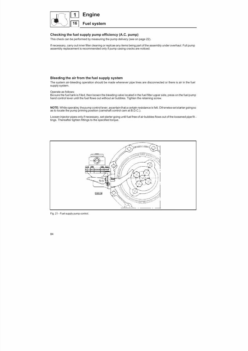
8/19/2019 Agrocompact f60 f70 f80 f90 Repair manual
http://slidepdf.com/reader/full/agrocompact-f60-f70-f80-f90-repair-manual 84/519
Checking the fuel supply pump efficiency (A.C. pump)This check can be performed by measuring the pump delivery (see on page 22).
If necessary, carry out inner filter cleaning or replcae any items being part of the assembly under overhaul. Full pumpassembly replacement is recommended only if pump casing cracks are noticed.
Bleeding the air from the fuel supply systemThe system air-bleeding operation should be made whenever pipe lines are disconnected or there is air in the fuelsupply system.
Operate as follows:Be sure the fuel tank is filled, then loosen the bleeding valve located in the fuel filter upper side, press on the fuel pumphand control lever until the fuel flows out without air bubbles. Tighten the retaining screw.
NOTE: While operating thepump control lever, ascertain that a certain resistance is felt. Otherwise set starter goingsoas to locate the pump priming position (camshaft control cam at B.D.C.).
Loosen injector pipes only if necessary, set starter going until fuel free of air bubbles flows out of the loosened pipe fit -tings. Thereafter tighten fittings to the specified torque.
Fig. 21 - Fuel supply pump control.
84
16
1 Engine
Fuel system
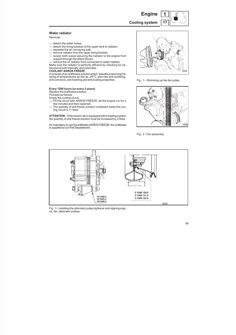
8/19/2019 Agrocompact f60 f70 f80 f90 Repair manual
http://slidepdf.com/reader/full/agrocompact-f60-f70-f80-f90-repair-manual 85/519
Water radiator Removal:
— detach the water hoses; — detach the fixing brackes of the upper tank to radiator; — separate the air conveying wall; — remove radiator from the upper fixing bracket; — loosen both scews securing the radiator to the engine front
support through the Silent-blocks. — remove the oil radiator front connected to water radiator.Make sure the radiator is perfectly efficient by checking for ob -structions both internally and externally.COOLANT AKROS FREEZEIt consists of an antifreeze solution which, besides preventing fre -ezing at temperatures as low as -39°C, also has anti-oxidizing,
anti-corrosive, anti-foaming and anti-scaling properties.
Every 1200 hours (or every 2 years):Replace the antifreeze solution.Proceed as follows:Empty the cooling circuit; — Fill the circuit with AKROS FREEZE, let the engine run for a
few minutes and then replenish. — The quantity of anti-freeze solution contained inside the coo -
ling circuit is 11 litres
ATTENTION - If the tractor cab is equippedwitha heating system,the quantity of anti-freeze solution must be increased by 2 litres.
It's mandatory to use the antifreeze AKROS FREEZE; this antifreezeis supplied by our Part Departement.
Fig - 3 - Installing the alternator pulley tightener and aligning engi -ne, fan, alternator pulleys.
Fig - 1 - Shimming up the fan pulley.
Fig - 2 - Fan assembly.
85
17
1Engine
Cooling system
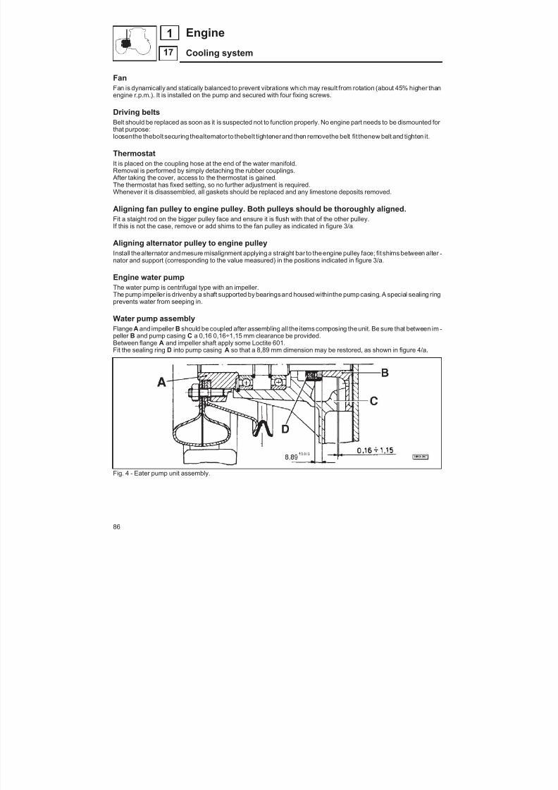
8/19/2019 Agrocompact f60 f70 f80 f90 Repair manual
http://slidepdf.com/reader/full/agrocompact-f60-f70-f80-f90-repair-manual 86/519
FanFan is dynamically and statically balanced to prevent vibrations which may result from rotation (about 45% higher than
engine r.p.m.). It is installed on the pump and secured with four fixing screws.
Driving beltsBelt should be replaced as soon as it is suspected not to function properly. No engine part needs to be dismounted for that purpose:loosenthe thebolt securing thealternator to thebelt tightenerand then removethe belt fit thenew belt and tighten it.
ThermostatIt is placed on the coupling hose at the end of the water manifold.Removal is performed by simply detaching the rubber couplings. After taking the cover, access to the thermostat is gained.The thermostat has fixed setting, so no further adjustment is required.Whenever it is disassembled, all gaskets should be replaced and any limestone deposits removed.
Aligning fan pulley to engine pulley. Both pulleys should be thoroughly aligned.Fit a staight rod on the bigger pulley face and ensure it is flush with that of the other pulley.If this is not the case, remove or add shims to the fan pulley as indicated in figure 3/a.
Aligning alternator pulley to engine pulleyInstall thealternator andmesure misalignment applying a straight bar to theengine pulley face; fit shims between alter -nator and support (corresponding to the value measured) in the positions indicated in figure 3/a.
Engine water pump
The water pump is centrifugal type with an impeller.The pump impeller is drivenby a shaft supported by bearingsand housed withinthe pump casing. A special sealing ringprevents water from seeping in.
Water pump assemblyFlange A and impeller B should be coupled after assembling all the items composing theunit. Be sure that between im -peller B and pump casing C a 0,16 0,16÷1,15 mm clearance be provided.Between flange A and impeller shaft apply some Loctite 601.Fit the sealing ring D into pump casing A so that a 8,89 mm dimension may be restored, as shown in figure 4/a.
Fig. 4 - Eater pump unit assembly.
86
17
Engine
Cooling system
1

8/19/2019 Agrocompact f60 f70 f80 f90 Repair manual
http://slidepdf.com/reader/full/agrocompact-f60-f70-f80-f90-repair-manual 87/519
ADJUSTING OF DRIVE BELT TENSION FOR ENGINETo adjust the belt tension operate as follows:
Tractor without air-conditioningsystem: loose thescrewA (see on thepicture below) and move thealternator in order toobtain a belt deflection of 20 mm approx, by exerting a finger pressure to the point of the longest section as indicated bythe arrow.NOTE - check with the hand on the middling point of the length tug of the belt.Tractor with air-conditioning system: loose the screw A (see on thepicture below) andmove thecompressor in order toobtaina belt deflection of 20 mm approx, by exerting a finger pressure to thepointof the longest section, For thesecondbelt, loose the screw B and move the alternator in order to obtain a belt deflection of 15 mm as indicated by the arrow.approx, by exerting a finger pressure to the point of the longest section, see the picture.
VERSION WITHOUT AIR-CONDITIONING SYSTEM
VERSION WITH AIR-CONDITIONING SYSTEM
87
17
1Engine
Cooling system

8/19/2019 Agrocompact f60 f70 f80 f90 Repair manual
http://slidepdf.com/reader/full/agrocompact-f60-f70-f80-f90-repair-manual 88/519
Fig.1 - Turbocharger.
Fig. 2 - Turbocharger and exhaust manifolds
Supercharging 70F3 F90The turbocharger assemblycovers thefunction of forcing more air
into thecylinders. This also allows thediesel fuel deliverycapacityto be proportionally increased.
Mixture increase is necessary to obtain greater engine power.
The turbocharger assembly is an extremely simple and rationaldesign and consists of a turbine and a compressor.
The turbine is operated by the exhaust gases from the engine (inthis way, a part of thegases’ kinetic energy which otherwisewouldbe wasted is recovered). The turbine drives the compressor,which compresses the air sucked in the cylinder intake duct thro -ugh the filter.
Tests A precise test on turbocharger efficiency can only be performedon a test bed.
Tests performed with turbocharger mounted on engine can onlygive approximate results.
Before starting checking operations make sure the engine fuelsupply system is operating correctly.
88
18
1 Engine
Intake and exhaust system

8/19/2019 Agrocompact f60 f70 f80 f90 Repair manual
http://slidepdf.com/reader/full/agrocompact-f60-f70-f80-f90-repair-manual 89/519
Checking pressure in the duct at turbocharger exit(Fig. 3).Removethe intakepipe plug and fit no. 5.9030.515.0 pressure ga -uge.
Start theengine and ensurethat both peak horsepowerspeedandmaximum torque speed pressures correspond to the specifica -tions indicated in related table to page 24.
Out of specifications readings may be due to poor air filter effi -ciency which should therefore be checked.
Also check couplings for distorsion or tearing; replace as neces -sary.
If trouble persists, removeturbocharger side coversandcheckim -peller blades for dirt build-up.
All carbon deposits should be removed using a plastic brush.
Checking exhaust pipesBe sure the exhaust pipes enable the exhaust gases to be pro -perly expelled; otherwise remove any carbon deposits.
If after performing theabovechecks theturbocharger is not opera -ting smoothly a thorough overhaul shall be carried out.
Removal (Fig. 4 and Fig. 5)Disconnect the lubricating pipes from cylinder block.
Loosen the pipe-to-turbocharger securing screws and remove to -gether with gaskets.
Ease-off clamps A and remove coupling B connecting turbochar -ger to intake manifold, (Fig, 4).
Loosen the two coupling fixing clamps placed between air filter and turbocharger and remove coupling.
Warning : convenientlyplug the turbocharger ducts to prevent anyforeign matters from entering.
Unloose the 4 screws securing the turbocharger A manifolds toexhaust manifold B as well as the nuts fastening the muffler sup -port C both to turbocharger and exhaust pipe, then removethe tur -bocharger, (Fig, 5).
Fig. 3 - Checkingpressure insidethe intakepipe.
Fig.4 - Manifolds-to-turbochargerconnectingco -uplings.
Fig. 5 - Turbocharger separation.
89
18
1Engine
Intake and exhaust system
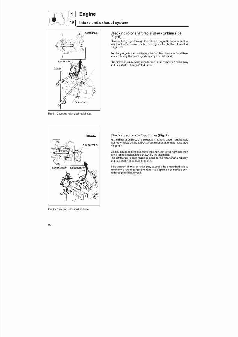
8/19/2019 Agrocompact f60 f70 f80 f90 Repair manual
http://slidepdf.com/reader/full/agrocompact-f60-f70-f80-f90-repair-manual 90/519
Fig. 6 - Checking rotor shaft radial play.
Fig. 7 - Checking rotor shaft end play.
Checking rotor shaft radial play - turbine side(Fig. 6)Place a dial gauge through the related magnetic base in such away that feeler rests on the turbocharger rotor shaft as illustratedin figure 6.
Set dial gauge to zero and press the hub first downward and thenupward taking the readings shown by the dial hand.
The difference in readings shall result in the rotor shaft radial playand this shall not exceed 0.46 mm.
Checking rotor shaft end play (Fig. 7)Fit the dial gauge through the related magnetic base in such a waythat feeler rests on the turbocharger rotor shaft end as illustratedin figure 7.
Set dial gauge to zero and move the shaft first to the right and thento the left taking readings shown by the dial hand.The difference in both readings shall be the rotor shaft end playand this shall not exceed 0.16 mm.
If the amount of axial or radial play exceeds the prescribed value,remove the turbocharger and take it to a specialised service cen -tre for a general overhaul.
90
18
1 Engine
Intake and exhaust system

8/19/2019 Agrocompact f60 f70 f80 f90 Repair manual
http://slidepdf.com/reader/full/agrocompact-f60-f70-f80-f90-repair-manual 91/519
Fig. 8 - Turbocharger assembly components.
Installing turbocharger on engine (Fig. 9)Secure the turbocharger assembly to its mounting. First fit coupling A to turbocharger assembly and next muffler sup -port B to the exhaust manifold fixing with the securing screws.Tighten first support B securing nuts and then the coupling securing nuts.Connect the lubricating pipes.Warning : Never race a cold engine.Run the engine just above low idling speed for a minute or two so as to allow the oil to warm upprogressively (the turbo -charger si lubricated by the engine oil) thus ensuring the rotor to be thoroughly lubricated. After some hours’ heavy work, let it run idling for a few minutesbefore stopping.This is to prevent the rotor from continu -ing to rotate through inertia without receiving a sufficient lubrication.Since theturbocharger under normal working rate rotates at very high speeds (55.000 ÷ 110.000 r.p.m.), even a fewse -conds’ oil lack may lead to irreparable damage.
Fig. 9 - Turbocharger assembly on engine.
91
18
1Engine
Intake and exhaust system
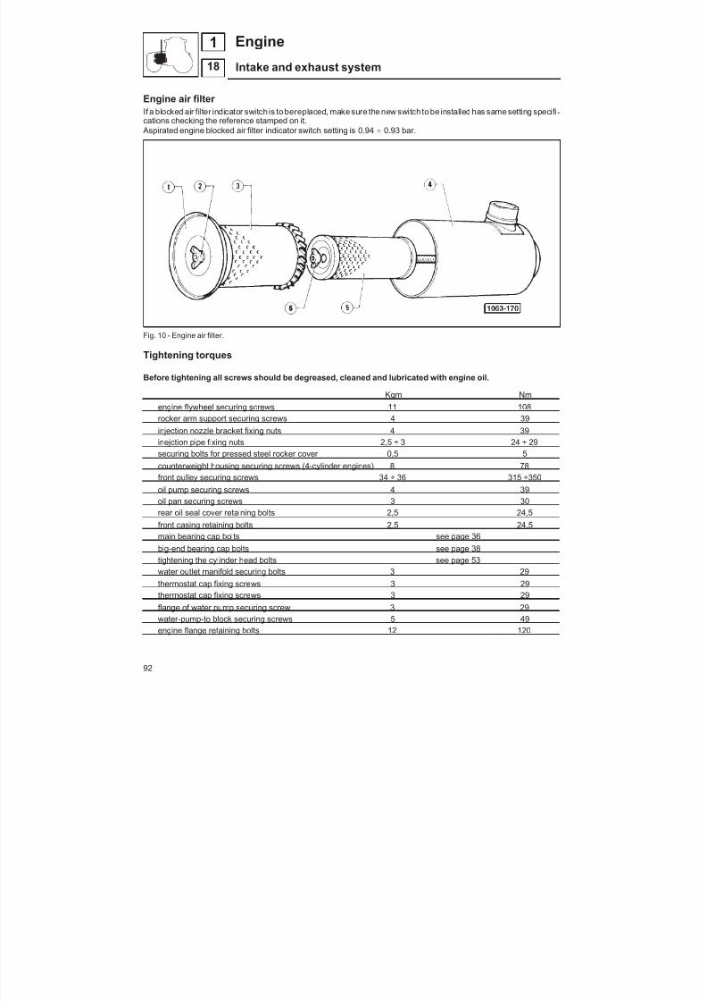
8/19/2019 Agrocompact f60 f70 f80 f90 Repair manual
http://slidepdf.com/reader/full/agrocompact-f60-f70-f80-f90-repair-manual 92/519
Engine air filter If a blocked air filter indicator switch is to bereplaced, make sure the new switch to be installed has samesetting specifi -cations checking the reference stamped on it. Aspirated engine blocked air filter indicator switch setting is 0.94 0.93 bar.
Fig. 10 - Engine air filter.
Tightening torques
Before tightening all screws should be degreased, cleaned and lubricated with engine oil.
Kgm Nmengine flywheel securing screws 11 108rocker arm support securing screws 4 39injection nozzle bracket fixing nuts 4 39inejction pipe fixing nuts 2,5 ÷ 3 24 ÷ 29securing bolts for pressed steel rocker cover 0,5 5counterweight housing securing screws (4-cylinder engines) 8 78front pulley securing screws 34 ÷ 36 315 ÷350oil pump securing screws 4 39oil pan securing screws 3 30rear oil seal cover retaining bolts 2,5 24,5front casing retaining bolts 2,5 24,5main bearing cap bolts see page 36big-end bearing cap bolts see page 38tightening the cylinder head bolts see page 53water outlet manifold securing bolts 3 29thermostat cap fixing screws 3 29thermostat cap fixing screws 3 29
flange of water pump securing screw 3 29water-pump-to block securing screws 5 49engine flange retaining bolts 12 120
92
18
1 Engine
Intake and exhaust system
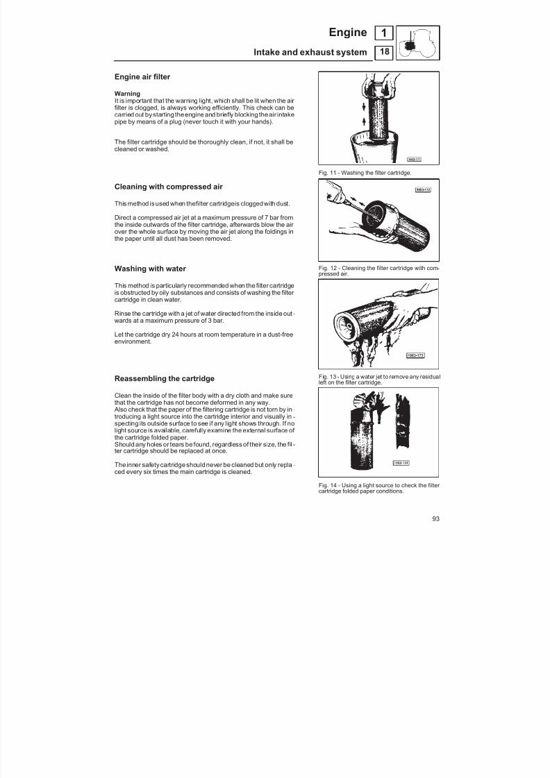
8/19/2019 Agrocompact f60 f70 f80 f90 Repair manual
http://slidepdf.com/reader/full/agrocompact-f60-f70-f80-f90-repair-manual 93/519
Engine air filter
WarningIt is important that the warning light, which shall be lit when the air filter is clogged, is always working efficiently. This check can becarried out by starting theengine and briefly blocking theair intakepipe by means of a plug (never touch it with your hands).
The filter cartridge should be thoroughly clean, if not, it shall becleaned or washed.
Cleaning with compressed air This method is used when thefilter cartridgeis cloggedwith dust.
Direct a compressed air jet at a maximum pressure of 7 bar fromthe inside outwards of the filter cartridge, afterwards blow the air over the whole surface by moving the air jet along the foldings inthe paper until all dust has been removed.
Washing with water
This method is particularly recommended when the filter cartridgeis obstructed by oily substances and consists of washing the filter cartridge in clean water.
Rinse the cartridge with a jet of water directed from the inside out -wards at a maximum pressure of 3 bar.
Let the cartridge dry 24 hours at room temperature in a dust-freeenvironment.
Reassembling the cartridge
Clean the inside of the filter body with a dry cloth and make surethat the cartridge has not become deformed in any way. Also check that the paper of the filtering cartridge is not torn by in -troducing a light source into the cartridge interior and visually in -specting its outside surface to see if any light shows through. If nolight source is available, carefully examine the external surface of the cartridge folded paper.Should any holes or tears be found, regardless of their size, the fil -ter cartridge should be replaced at once.
The inner safety cartridgeshouldnever be cleaned but only repla -ced every six times the main cartridge is cleaned.
Fig. 11 - Washing the filter cartridge.
Fig. 12 - Cleaning the filter cartridge with com -pressed air.
Fig. 13 - Using a water jet to remove any residualleft on the filter cartridge.
Fig. 14 - Using a light source to check the filter cartridge folded paper conditions.
93
18
1Engine
Intake and exhaust system
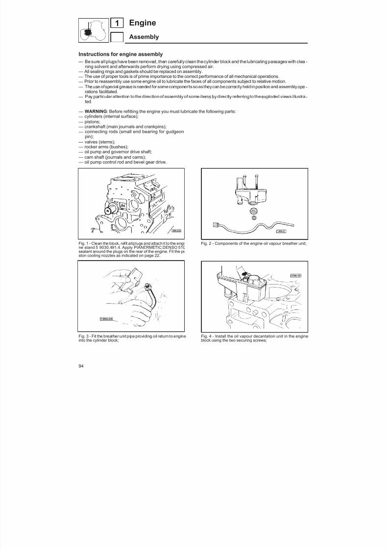
8/19/2019 Agrocompact f60 f70 f80 f90 Repair manual
http://slidepdf.com/reader/full/agrocompact-f60-f70-f80-f90-repair-manual 94/519
Instructions for engine assembly — Be sure all plugs have been removed, then carefully clean thecylinder block and the lubricating passages with clea -
ning solvent and afterwards perform drying using compressed air. — All sealing rings and gaskets should be replaced on assembly. — The use of proper tools is of prime importance to the correct performance of all mechanical operations. — Prior to reassembly use some engine oil to lubricate the faces of all components subject to relative motion. — The use ofspecial grease isneededfor somecomponents soas theycan becorrectly heldinposition and assemblyope -
rations facilitated. — Pay particular attention to thedirectionof assembly of some items by directly referringto theexploded views illustra -
ted.
— WARNING : Before refitting the engine you must lubricate the following parts: — cylinders (internal surface); — pistons; — crankshaft (main journals and crankpins);
— connecting rods (small end bearing for gudgeonpin); — valves (stems); — rocker arms (bushes); — oil pump and governor drive shaft; — cam shaft (journals and cams); — oil pump control rod and bevel gear drive.
Fig. 1 - Clean the block, refit allplugs and attach it to the engi -ne stand 5 9030.491.4. Apply PIANERMETIC DENSO 510sealant around the plugs on the rear of the engine. Fit the pi -ston cooling nozzles as indicated on page 22.
Fig. 3 - Fit the breather unit pipe providing oil return to engineinto the cylinder block;
Fig. 2 - Components of the engine oil vapour breather unit;
Fig. 4 - Install the oil vapour decantation unit in the engineblock using the two securing screws;
94
1 Engine
Assembly

8/19/2019 Agrocompact f60 f70 f80 f90 Repair manual
http://slidepdf.com/reader/full/agrocompact-f60-f70-f80-f90-repair-manual 95/519
Fig. 5 - Install the piston rings on piston and then connect pi -ston to connecting rod;
Fig. 7 - Fit the O-rings on the cylinder;
Fig. 9 - Orient the piston combustion chamber towards the in - jection pump side, secure the piston-connecting rod as -sembly by means of no. 5.9030.631.4/10 equipment, thenturn the engine upside down;
Fig. 6 - Fitting the piston-connecting rod assembly into thecylinder;
Fig. 8 - Installing the cylinder-piston-connecting rod as -sembly in the engine block;
Fig. 10 - Checking for correct cylinder and assembled pistonpositioning at T.D.C. Measure the piston protrusion fromcylinder andselectthe suitedgaskettype to be fittedbetweencylinder and cylinder head as shown on page 31.
95
1Engine
Assembly
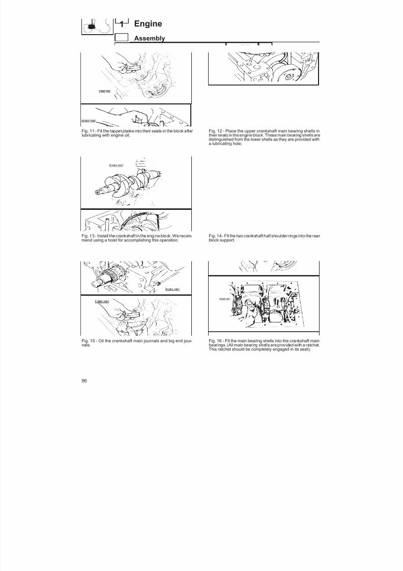
8/19/2019 Agrocompact f60 f70 f80 f90 Repair manual
http://slidepdf.com/reader/full/agrocompact-f60-f70-f80-f90-repair-manual 96/519
Fig. 11 - Fit the tappet plates into their seats in the block after lubricating with engine oil;
Fig. 13 - Install the crankshaft in the engine block. We recom -mend using a hoist for accomplishing this operation;
Fig. 15 - Oil the crankshaft main journals and big end jour -
nals;
Fig. 12 - Place the upper crankshaft main bearing shells intheir seats in the engine block. These main bearing shells aredistinguished from the lower shells as they are provided witha lubricating hole;
Fig. 14- Fit the two crankshaft half shoulder rings into the rear block support;
Fig. 16 - Fit the main bearing shells into the crankshaft main
bearings. (All main bearing shells areprovided with a ratchet.This ratchet should be completely engaged in its seat);
96
1 Engine
Assembly
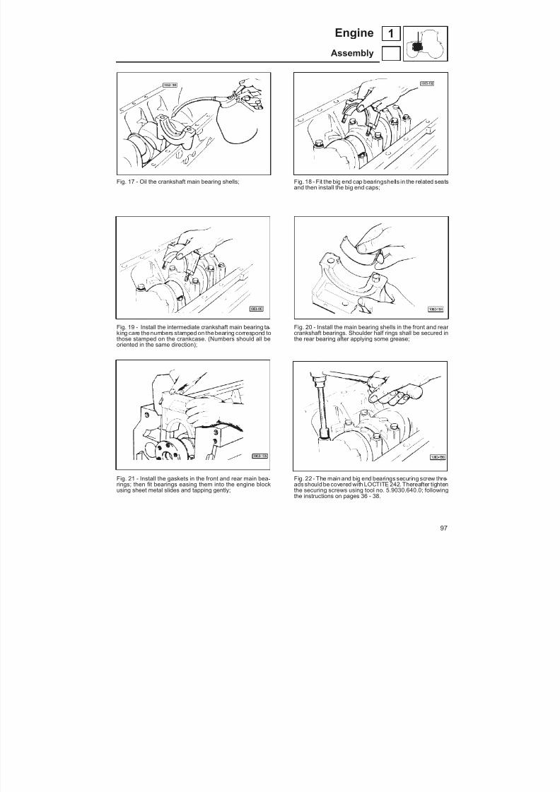
8/19/2019 Agrocompact f60 f70 f80 f90 Repair manual
http://slidepdf.com/reader/full/agrocompact-f60-f70-f80-f90-repair-manual 97/519
Fig. 17 - Oil the crankshaft main bearing shells;
Fig. 19 - Install the intermediate crankshaft main bearing ta -king care the numbers stamped on the bearing correspond tothose stamped on the crankcase. (Numbers should all beoriented in the same direction);
Fig. 21 - Install the gaskets in the front and rear main bea -rings; then fit bearings easing them into the engine blockusing sheet metal slides and tapping gently;
Fig. 18 - Fit the big end cap bearingshells in the related seatsand then install the big end caps;
Fig. 20 - Install the main bearing shells in the front and rear crankshaft bearings. Shoulder half rings shall be secured inthe rear bearing after applying some grease;
Fig. 22 - The main and big end bearings securing screw thre -adsshould be covered with LOCTITE 242. Thereafter tightenthe securing screws using tool no. 5.9030.640.0; followingthe instructions on pages 36 - 38.
97
1Engine
Assembly
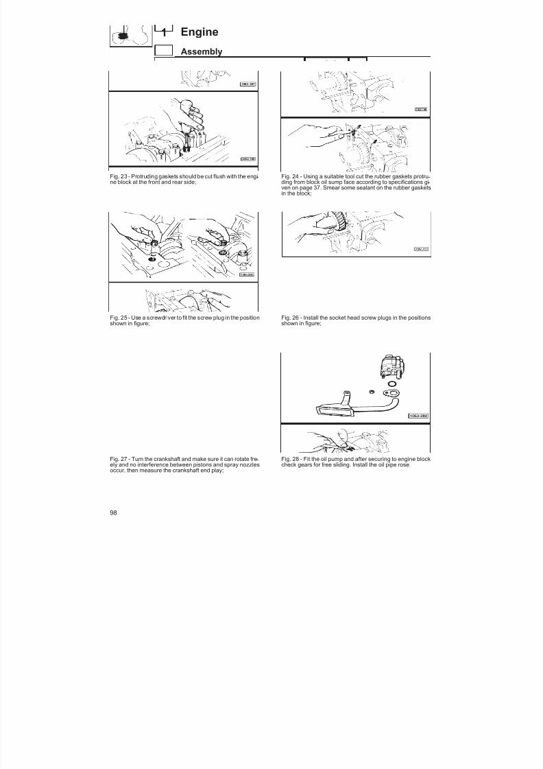
8/19/2019 Agrocompact f60 f70 f80 f90 Repair manual
http://slidepdf.com/reader/full/agrocompact-f60-f70-f80-f90-repair-manual 98/519
Fig. 23 - Protruding gaskets should be cut flush with the engi -ne block at the front and rear side;
Fig. 25 - Use a screwdriver to fit the screw plug in the positionshown in figure;
Fig. 27 - Turn the crankshaft and make sure it can rotate fre -
ely and no interference between pistons and spray nozzlesoccur, then measure the crankshaft end play;
Fig. 24 - Using a suitable tool cut the rubber gaskets protru -ding from block oil sump face according to specifications gi -ven on page 37. Smear some sealant on the rubber gasketsin the block;
Fig. 26 - Install the socket head screw plugs in the positionsshown in figure;
Fig. 28 - Fit the oil pump and after securing to engine block
check gears for free sliding. Install the oil pipe rose;
98
1 Engine
Assembly
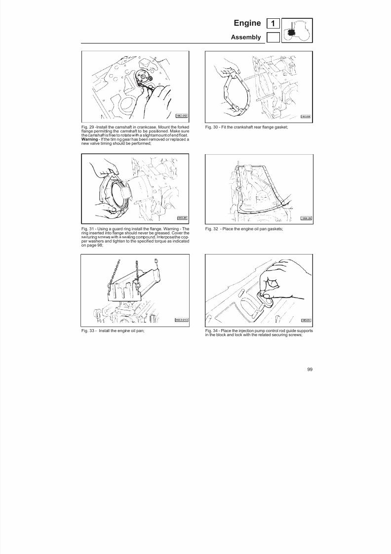
8/19/2019 Agrocompact f60 f70 f80 f90 Repair manual
http://slidepdf.com/reader/full/agrocompact-f60-f70-f80-f90-repair-manual 99/519
Fig. 29 -Install the camshaft in crankcase. Mount the forkedflange permitting the camshaft to be positioned. Make surethecamshaft is free to rotatewith a slightamount of endfloat.Warning - If the timing gear has been removed or replaced anew valve timing should be performed;
Fig. 31 - Using a guard ring install the flange. Warning - Thering inserted into flange should never be greased. Cover thesecuring screws with a sealing compound. Interposethe cop -per washers and tighten to the specified torque as indicatedon page 98;
Fig. 33 - Install the engine oil pan;
Fig. 30 - Fit the crankshaft rear flange gasket;
Fig. 32 - Place the engine oil pan gaskets;
Fig. 34 - Place the injection pump control rod guide supports
in the block and lock with the related securing screws;
99
1Engine
Assembly

8/19/2019 Agrocompact f60 f70 f80 f90 Repair manual
http://slidepdf.com/reader/full/agrocompact-f60-f70-f80-f90-repair-manual 100/519
Fig. 35 - Insert the injection pump control rod in the its seat inthe cylinder block along with pressure spring and stop cap.Make sure it is free to move inside the guide supports;
Fig. 37 - FOR TRAKTORS WITH ELECTRONICGOVERNOR ONLY - After inserting a sealing ring on thestem fit the engine actuator support in the block;
Fig. 39 - Fix the square transmission to the block tightening
the related securing screws;
Fig. 36 - ONLY FOR TRAKTORS WITH MECHANICALGOVERNOR ONLY - Assemble the square transmissioncontrolling both engine governor and oil pump. As to as -sembly and adjustment procedures see instructions on page60;
Fig. 38 - FOR TRAKTORS WITH MECHANICALGOVERNOR ONLY - Install the square transmission in itsseat in theblock placing the special backlash adjusting shimsbetween the gear teeth (see instructions on page 64);
Fig. 40 - Only if necessary, determine the shim pack amounts
to be fit between injections pumps and engine block (see in -structions on page 78);
100
1 Engine
Assembly

8/19/2019 Agrocompact f60 f70 f80 f90 Repair manual
http://slidepdf.com/reader/full/agrocompact-f60-f70-f80-f90-repair-manual 101/519
Fig. 41 - If the timing gear has been removed from the shaftcarry out valve timing for timing the engine as indicated onpage 77;
Fig. 43 - After the timing gear has been secured to shaft, fitthe idler gear taking care the chiselings on teeth be in thesameline. If one of these three gears mustbe replaced, valvetiming procedure shall be repeated;
Fig. 45 - Place the isogene gasket between engine block and
timing case;
Fig. 42 - After smearing the shim faces with some sealing ad -hesive place theshim packs between pumps and block. Sub -sequently perform injection pump installation;
Fig. 44 - Fit some locating pins or studs to centre the timingcase correctly during assembly;
Fig. 46 - The timing case should be installed paying attention
not to damage the sealing ring lip fitted inside;
101
1Engine
Assembly

8/19/2019 Agrocompact f60 f70 f80 f90 Repair manual
http://slidepdf.com/reader/full/agrocompact-f60-f70-f80-f90-repair-manual 102/519
Fig. 47 - Remove excess gasket from the face used to fix ex -ternal applications;
Fig. 49 - Fit no. 5.9030.634.0 tool as shown in figure to obtainthorough concentricity between sealing ring and crankshaftas well as a full coplanarity of the external application fixingfaces, then fully tighten the timing case securing screws. Re -move the tool;
Fig. 51 - Fit gaskets between cylinder heads and cylinders
(see instructions on page 31);
Fig. 48 - Insert all timing case securing screws but do not tig -hten fully;
Fig. 50 - Using a suitable plug fit the pulley hub to thecrankshaft;
Fig. 52 - After preassembling the heads install on engine;
102
1 Engine
Assembly

8/19/2019 Agrocompact f60 f70 f80 f90 Repair manual
http://slidepdf.com/reader/full/agrocompact-f60-f70-f80-f90-repair-manual 103/519
Fig. 53 - Insert the tappet rods, fit the rocker armsand the roc -ker arm supports;
Fig. 55- Using a specialtool fit the rod cover pipes and the po -sitioning springs;
Fig. 57 - Adjust valve and rocker arm clearance;
Fig. 54 - Install the injection nozzles in their seats;
Fig. 56 - Using a plug thoroughly insert the injection nozzlesin their seats orienting the fuel rejection hole towards the fi -xing bracket. Install the injection nozzle fixingbracketstighte -ning the securing screws to the torque specified in the tableon page 92;
Fig. 58 - Oil valve caps and valve springs;
103
1Engine
Assembly
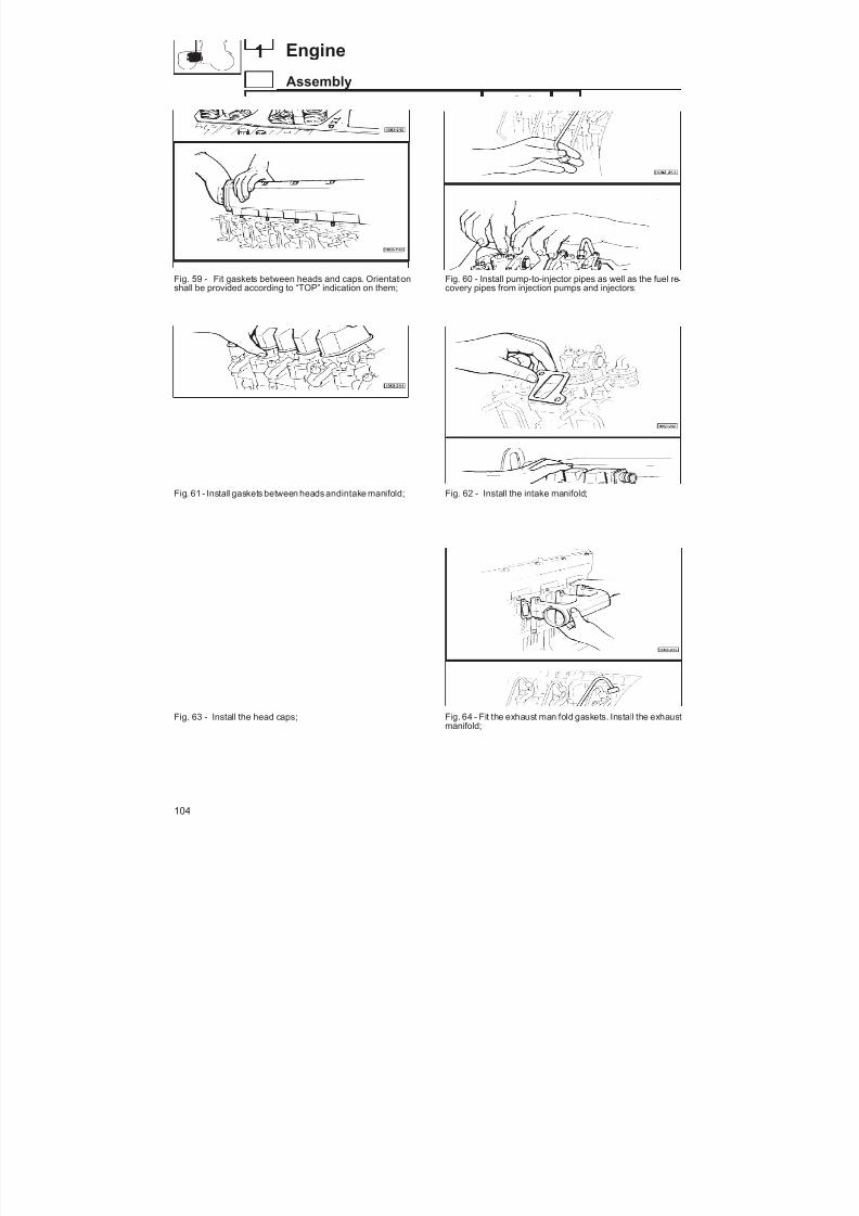
8/19/2019 Agrocompact f60 f70 f80 f90 Repair manual
http://slidepdf.com/reader/full/agrocompact-f60-f70-f80-f90-repair-manual 104/519
Fig. 59 - Fit gaskets between heads and caps. Orientationshall be provided according to “TOP” indication on them;
Fig. 61 - Install gaskets between heads andintake manifold;
Fig. 63 - Install the head caps;
Fig. 60 - Install pump-to-injector pipes as well as the fuel re -covery pipes from injection pumps and injectors;
Fig. 62 - Install the intake manifold;
Fig. 64 - Fit the exhaust manifold gaskets. Install the exhaustmanifold;
104
1 Engine
Assembly

8/19/2019 Agrocompact f60 f70 f80 f90 Repair manual
http://slidepdf.com/reader/full/agrocompact-f60-f70-f80-f90-repair-manual 105/519
Fig. 65 - On turbocharged engines: install the turbocharger assembly following the instructions given on page 91;
Fig. 67 - On turbocharged engines: place the rubber hoseconnecting the turbocharger to the intake manifold and secu -re with two clamps;
Fig. 69 - For tractors equipped with electronic governors
only: fit the actuator assembly;
Fig. 66 - On turbocharged engines: connect the turbocharger oil delivery and return pipes;
Fig. 68 - FOR TRAKTORS WITH MECHANICALGOVERNOR ONLY - Install the engine governor taking carethe control frok engages in the pump control rod ratchet cor -rectly; make sure it is properly fit in ist seat and then tightenwith both securing screws;
Fig. 70 - Fitbthe oil fuel filter and engine oil filters; then fit the
fuel filters and the fuel prefilter. Connect the fuel lines
105
1Engine
Assembly
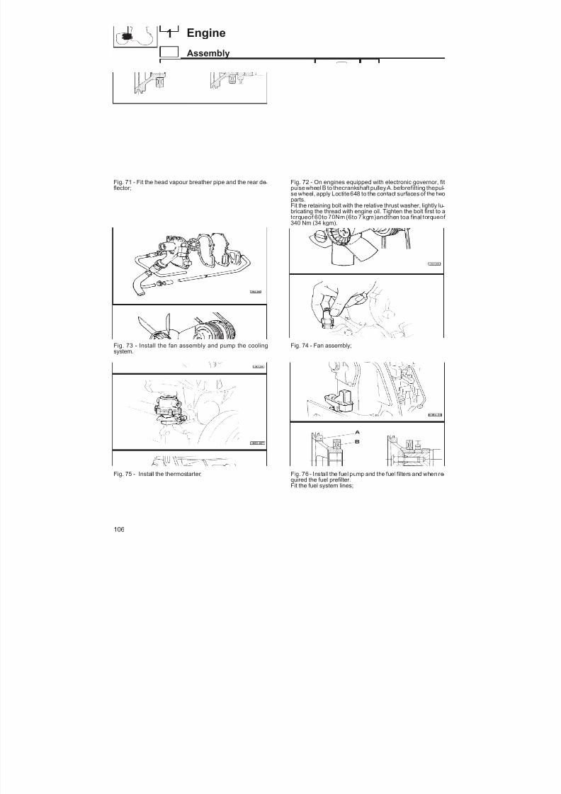
8/19/2019 Agrocompact f60 f70 f80 f90 Repair manual
http://slidepdf.com/reader/full/agrocompact-f60-f70-f80-f90-repair-manual 106/519
Fig. 71 - Fit the head vapour breather pipe and the rear de -flector;
Fig. 73 - Install the fan assembly and pump the coolingsystem.
Fig. 75 - Install the thermostarter;
Fig. 72 - On engines equipped with electronic governor, fitpulse wheel B to thecrankshaft pulleyA. beforefitting thepul -se wheel, apply Loctite 648 to the contact surfaces of the twoparts.Fit the retaining bolt with the relative thrust washer, lightly lu -bricating the thread with engine oil. Tighten the bolt first to atorqueof 60to 70Nm (6to 7 kgm)andthen toa final torqueof 340 Nm (34 kgm).
Fig. 74 - Fan assembly;
Fig. 76 - Install the fuel pump and the fuel filters and when re -
quired the fuel prefilter.Fit the fuel system lines;
106
1 Engine
Assembly
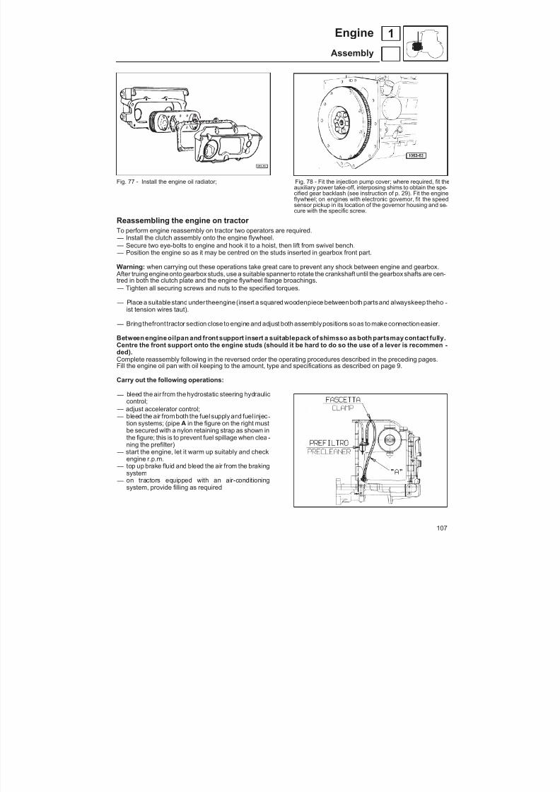
8/19/2019 Agrocompact f60 f70 f80 f90 Repair manual
http://slidepdf.com/reader/full/agrocompact-f60-f70-f80-f90-repair-manual 107/519
Fig. 77 - Install the engine oil radiator; Fig. 78 - Fit the injection pump cover; where required, fit theauxiliary power take-off, interposing shims to obtain the spe -cified gear backlash (see instruction of p. 29). Fit the engineflywheel; on engines with electronic governor, fit the speedsensor pickup in its location of the governor housing and se -cure with the specific screw.
Reassembling the engine on tractor To perform engine reassembly on tractor two operators are required. — Install the clutch assembly onto the engine flywheel. — Secure two eye-bolts to engine and hook it to a hoist, then lift from swivel bench. — Position the engine so as it may be centred on the studs inserted in gearbox front part.
Warning: when carrying out these operations take great care to prevent any shock between engine and gearbox. After truing engine onto gearbox studs, use a suitable spanner to rotate the crankshaft until the gearbox shafts are cen-tred in both the clutch plate and the engine flywheel flange broachings.
— Tighten all securing screws and nuts to the specified torques.
— Place a suitable standunder theengine (insert a squared woodenpiece betweenboth parts and alwayskeep theho -ist tension wires taut).
— Bring thefront tractor section close to engine and adjust both assemblypositions soas to make connectioneasier.
Between engine oilpan and front support insert a suitablepack of shimsso as both partsmay contact fully.Centre the front support onto the engine studs (should it be hard to do so the use of a lever is recommen -ded).Complete reassembly following in the reversed order the operating procedures described in the preceding pages.Fill the engine oil pan with oil keeping to the amount, type and specifications as described on page 9.
Carry out the following operations:
— bleed the air from the hydrostatic steering hydrauliccontrol;
— adjust accelerator control; — bleed the air fromboth the fuel supply and fuel injec -
tion systems; (pipe A in the figure on the right mustbe secured with a nylon retaining strap as shown inthe figure; this is to prevent fuel spillage when clea -ning the prefilter)
— start the engine, let it warm up suitably and checkengine r.p.m.
— top up brake fluid and bleed the air from the brakingsystem
— on tractors equipped with an air-conditioningsystem, provide filling as required
107
1Engine
Assembly

8/19/2019 Agrocompact f60 f70 f80 f90 Repair manual
http://slidepdf.com/reader/full/agrocompact-f60-f70-f80-f90-repair-manual 108/519
mengine won’t runwhen started
engine difficult to startor won’t restart after astop
clear exhaust smoke
check batterycharge
starter failure
check fuel level
inefficient injectionsystem
Checkthermostarter
Insufficientcompression
check injectionpump setting
check injectors for proper cleanliness
charged battery
discharged battery
consult a motor ve -hicle electrician for having the defecti -ve parts replaced
top up fuel level intank
inspect fuel filter for cleanliness
a metal noise is he -ard when engineidles
air in the fuelsystem
out-of-calibrationinjection nozzles
clean or replace
check clearancebetween valvesand rockers
perform a new set -ting
make sure there isno excessive clea-rance between val -ves and valve gui -
des
clean scrupulously
battery terminalsoxidized
recharge battery
clean filter, replaceif necessary
out-of-adjustmentpumps, excessiveadvance
perform air blee -ding
defective fuelpump
or pump control
calibrate
restore correct bac -klash
check valves for ef-ficient operatingconditions
check piston ringsand cylinders for wear
replace worn-outparts
clean battery con -tacts and tightenterminals
recalibrate thepumps
replace defectiveparts
grind or replacevalves, cylinder head gaskets andpiston rings
replace pistons andcylinders
replace worn-outparts
108
1 Engine
Diagnosing malfunctions

8/19/2019 Agrocompact f60 f70 f80 f90 Repair manual
http://slidepdf.com/reader/full/agrocompact-f60-f70-f80-f90-repair-manual 109/519
dark exhaust smoke
poor engine responseafter a sudden accele-ration
engine won’t keepconstant r.p.m.
engine overheating
check air filter car -tridge for blocking
out-of-calibrationengine governor
check air filter car -tridge for clogging
make sure no air iswithin the fuelsystem
insufficient com -pression in thecylinders
make sure neither air nor water are inthe injectionsystem
check belt tension
check coolingsystem efficiency
inspect pumps for proper timing
measure pressure
in the duct at com -pressor exit
clean or replace
check injectors for proper efficiency
adjust governor and provide a newcalibration
check for proper fuel filter cleanli -ness
bleed the air insystem
check clearancebetween valvesand rockers
empty the tank andfill with decanteddiesel fuel
check injectors for correct calibration
operate the relatedbelt tightener
clean carefully
retime as neces -sary
check injectors for correct calibration
clean the turbo -
charger
restore calibrationaccording to speci -fications
clean or replace fil -ters
restore correct cle -arance
check valve effi -ciency
bleed air fromsystem
restore specifiedcalibration
bleed the system
grind or replacevalves, cylinder head gaskets andpiston rings
replace pistons andcylinders
109
1Engine
Diagnosing malfunctions

8/19/2019 Agrocompact f60 f70 f80 f90 Repair manual
http://slidepdf.com/reader/full/agrocompact-f60-f70-f80-f90-repair-manual 110/519
Gearshift clutch
General specifications
The clutch, a single stage type, comprises a friction disc, a pressure plate and a diaphragm spring.The hydrostatic control is self-adjusting: a master cylinder operated by the pedal directs oil to the slave cylinder moun -ted to the left hand side of the intermediate housing, which in turn operates the clutch release lever.
Technical specifications AGROCOMPACT AGROCOMPACT AGROCOMPACT F60 - 70F3 70F4 - F80 - F90
Type of clutch single disc dry single disc dry single disc dryorganic facing organic facing cerametallik facing
Type of operation hydrostatic with automatic take-up of free travel
Disc p/n 009.6913.3 009.6924.3/20 009.9770.3Disc diameter mm 279,4 310 310Minimum permissible thickness of disc mm 6 6 9,7Thickness of friction disc mm 8 5 0 3
0 3, ,,
-
+ 8 5 0 30 3, ,
,-
+ 10 -
+
0 20 2..
Type of facing material on friction disc TEXTAR T385 TEXTAR T385 UA 330 DXType of master cylinder Benditalia 3/4"Type of oil AKROS MATIC
Fig. 1 - Engine rpm pickup. (1 st version)
Spring specifications to Belleville washer for theclutch engagementLoad on the pressure plate Nm 11000
CAUTION: In theevent the transmission being split to gain accessto the clutch assembly, the pickup (A, fig. 1) must be removed toavoid its being damaged by the teeth of the engine flywheel.
IMPORTANT: If there are signs of scoring on the surface of the flywheel, the surface must be machined smooth following the di - rections of page 45.
IIMPORTANT: In the event of the friction disc being removed, care must be taken during refitment to position
the components correctly, as indicated, since the disc is not symmetrical.
110
23
2 Clutch and transmission
Clutch

8/19/2019 Agrocompact f60 f70 f80 f90 Repair manual
http://slidepdf.com/reader/full/agrocompact-f60-f70-f80-f90-repair-manual 111/519
Fig. 2 - Clutch unit for F60 - 70F3 Fig. 3 - Clutch unit for 70F4 - F80 - F90
Clu
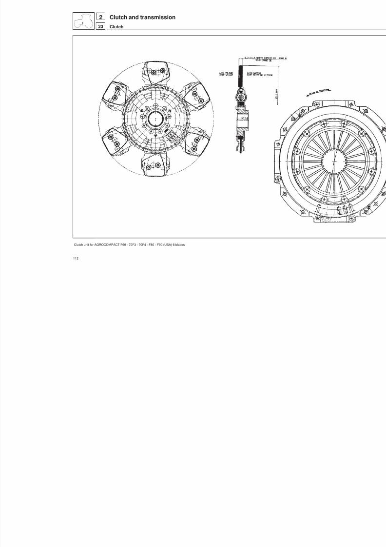
8/19/2019 Agrocompact f60 f70 f80 f90 Repair manual
http://slidepdf.com/reader/full/agrocompact-f60-f70-f80-f90-repair-manual 112/519
Clutch unit for AGROCOMPACT F60 - 70F3 - 70F4 - F80 - F90 (USA) 6 blades
112
Clutch and transmission
Clutch
223

8/19/2019 Agrocompact f60 f70 f80 f90 Repair manual
http://slidepdf.com/reader/full/agrocompact-f60-f70-f80-f90-repair-manual 113/519
Fig. 4 - Components of clutch assembly
113
23
2Clutch and transmission
Clutch

8/19/2019 Agrocompact f60 f70 f80 f90 Repair manual
http://slidepdf.com/reader/full/agrocompact-f60-f70-f80-f90-repair-manual 114/519
Fig. 5 - Checking clutch disk thickness.
Fig. 6 - Clutch assembly hydraulic operating
cylinder.
Fig. 7 - Checking operating cylinder inside springefficiency.
Fig. 8 - Bleeding the air from the clutch hydrauliccircuit.
Fig. 9 - Installing clutch assembly through n. 5.9030.256.4/10 equipment.
Cecking clutchCheck the disk lining for signsof chipping and the disk friction facefor scoring which maypreventthe clutch from operating properly.
Check that the sliding surface of the engine flywheel is not scored;if signs of scoring areevident, machine the surface as indicated onpage 45.Check the disk thrust plate for scoring or bluish areas caused bytempering and also ensure the diaphragm-typespring has not lostits efficiency; if so the whole clutch assembly shall be replaced.
Besure the clutch disk is free to move in its housing and the frictionlining securing rivets are duly riveted.Should any wear be found on the thrust bearing or the diap -hragm-type spring, an exhaustive check over the spring operatingconditions installed in the disk thrust lever operating cylinder (seeFig. 6) shall be performed; replace if necessary.On reassembly ascertain dimension A (see Fig. 6) between theoperating cylinder fixing face and the push rod contacting the en -gagement lever is 195 mm.
NOTE: To facilitate correct clutch disk assembly the use of no.5.9030.256.4/10 centering tool is recommended.Warning: With engine running, never ride the clutch pedal withyour foot to prevent the clutch disk from being damaged becauseof overheating.Important: The thrust bearingis prelubricated, and must never onany account be cleaned with fuel oil or other solvents as these willrender the prelubrication treatment ineffective.
Adjusting clutch control pedalMake sure thedistance between pump fixing surface andforkholecentre is 95 1 (Fig. 15) otherwise loosen nut A and operate adju -sting stay rod B (Fig. 15).
Bleeding air from the hydraulic circuitOperate the clutch pedal several times, then keeping the clutchpedal in fully depressed position, slightly unscrew and soon aftertighten the air bleeding screw valve again (this being located on
thrust lever operating cylinder).This operation should be repeatedas many times as the oil flows out of the bleeding screw valve wit -hout air bubbles.
114
23
2 Clutch and transmission
Clutch
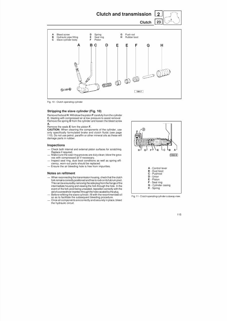
8/19/2019 Agrocompact f60 f70 f80 f90 Repair manual
http://slidepdf.com/reader/full/agrocompact-f60-f70-f80-f90-repair-manual 115/519
A Bleed screw D Spring G Push rodB Hydraulic pipe fitting E Seal ring H Rubber bootC Slave cylinder body F Piston
Fig. 10 - Clutch operating cylinder
Stripping the slave cylinder (Fig. 10)Removetheboot H. Withdrawthepiston F carefullyfromthe cylinderC , blasting with compressed air at low pressure to assist removal.Remove the spring D from the cylinder and loosen the bleed screwA.Remove the seals E fom the piston F.CAUTION: When cleaning the components of the cylinder, useonly specifically formulated brake and clutch fluids (see page110). Do not use petrol, paraffin or other mineral oils as these willdamage parts in rubber.
Inspections — Check both internal and external piston surfaces for scratching.
Replace if required.
— Make sure the seal ring grooves are duly clean; blow the groo -ves with compressed air if necessary. — Inspect seal ring, dust boot conditions as well as spring effi -
ciency, worn-out parts should be replaced. — Ensure the air bleeding hole is free from impurities.
Notes on refitment — When reconnecting the transmission housing, check that the clutch
fork remainscorrectlypositioned andfree to rock onitsfulcrum pivot.This can beensuredby removing the sideplugfromthe flange oftheintermediate housing and viewing the fork through the hole. In theevent of the fork pivot being unseated, reposition correctly with theaid ofa screwdriver insertedthroughthe holevacated bythe plug.
— Before refitting the slave cylinder, fill with the recommended oilso as to facilitate the subsequent bleeding procedure. — Once all components arecorrectly andsecurely in place,bleed
the hydraulic circuit.
A - Control leverB - Dust bootC - PushrodD - UnionE - PistonF - Seal ringG - Cylinder casingH - Spring
Fig. 11 - Clutchoperatingcylinder cutaway view.
115
23
2Clutch and transmission
Clutch

8/19/2019 Agrocompact f60 f70 f80 f90 Repair manual
http://slidepdf.com/reader/full/agrocompact-f60-f70-f80-f90-repair-manual 116/519
A Hydraulic pump F - Spring M - Spacer ring R - Snap ringB - Delivery pipe union G - Spring holder N - Piston S - Guard bootC - Delivery pipe H - Screw O - Seal ring T - NutD - Clamp I - Shoulder ring P - Rod U - YokeE - Union L - Seal ring Q - Support disk
Fig. 12 - Clutch hydraulic pump parts.
Stripping the master cylinderReferring to figure 14, remove the protective boot E , dislodge the circlip B and withdraw the rod D together with thedisc C .Remove the piston together with the spacer, the seal, the backup washer and the spring beneath.
Fig. 13 - Clutch pump control positioning.A - LocknutB - Yoke
Fig. 14 - Pump control seal ring.A - Pump D - RodB - Snap ring E - Guard bootC - Support disk
116
23
2 Clutch and transmission
Clutch

8/19/2019 Agrocompact f60 f70 f80 f90 Repair manual
http://slidepdf.com/reader/full/agrocompact-f60-f70-f80-f90-repair-manual 117/519
Inspections and checksWARNING: To clean and wash the hydraulic pump components use only the oil type recommended for brakes andclutch (see page 110). Never use petrol, kerosene or other mineral oils to prevent damaging the rubber parts.Inspect both internal and external piston sliding surfaces for scratching. Replace if required.Make sure the seal ring grooves are duly clean; blow the grooves with compressed air if necessary.Inspect seal ring, dust boot conditions as well as spring efficiency, worn-out parts should be replaced.Inspectall pumpinternal compartments, apertures andpassages and make sure these areproperly clean andfreefromforeign matters.Check that the spring is neither lazy nor deformed; replace if necessary.
ReassemblyReassemble the cylinder, repeating the disassembly steps in reverse order and observing the following directions:— Lubricate surfaces engaged in relative sliding contact, using the recommended oil (see page 110).— Verifycorrect operation of thecylinder, makingcertain that thepiston is able to complete its full strokeunimpeded.In the event that the fork linking the master cylinder with the pedal has been removed, check that with the push rod fullyextended, the distance between the referencesurface of thecylinder and the centre of the hole in the fork is as indicatedin figure 15.If not (referring to fig 13), remove the boot, loosen the lock nut A and screw or unscrew the fork B to obtain the prescri-bed clearance, then retighten the lock nut and reposition the boot.
Fig. 15 - Section view of clutch master cylinder
Clutch greasing points.Apply Molikote Gn-plus at all the points indicated in the figurewith letter A.Fit part B with Loctite 270.Fit pin C with Loctite 601.
Fitting the P.T.O. shaft oil sealBefore fitting the oil seal 2.1529.517.0 apply Loctite 222 tothe outer face A indicated in the figure.
117
23
2Clutch and transmission
Clutch

8/19/2019 Agrocompact f60 f70 f80 f90 Repair manual
http://slidepdf.com/reader/full/agrocompact-f60-f70-f80-f90-repair-manual 118/519
clutch slips
clutch jerks
clutch fails to disenga -ge
clutch noisy when di -sengaged
lubricant in clutch
housing
clutch worn
thrust bearing stic -
king
clutch disk surfa -ces dirty
clutch disk warped
difficulty in enga -ging gears whenengine running
worn parts in clutchengagement me -chanism
renew the front ge -
arbox oil seal andthe rear engine oilseal
check condition ofclutch disk
clean surfaces and
apply grease
clean the frictionsurfaces
clutch disk surfa -ces dirty
clutch disk worn
plate seals loose
clutch disk warped
hydraulic pumpinefficient
clutch disk stuck toflywheel
replace parts
clean oil seal con -
tact surfaces withpetrol
check condition ofthe spring disk
replace thrust bea -
ring
replace clutch disk
replace clutch disk
replace clutch disk
replace disk
check the stroke ofthe clutch controlpiston and replaceany worn parts
clean contact sur -faces with a wirebrush and petrol
replace disk
fit new clutch as -sembly
clean or replace the
disk
118
23
2 Clutch and transmission
Diagnosing malfunctions
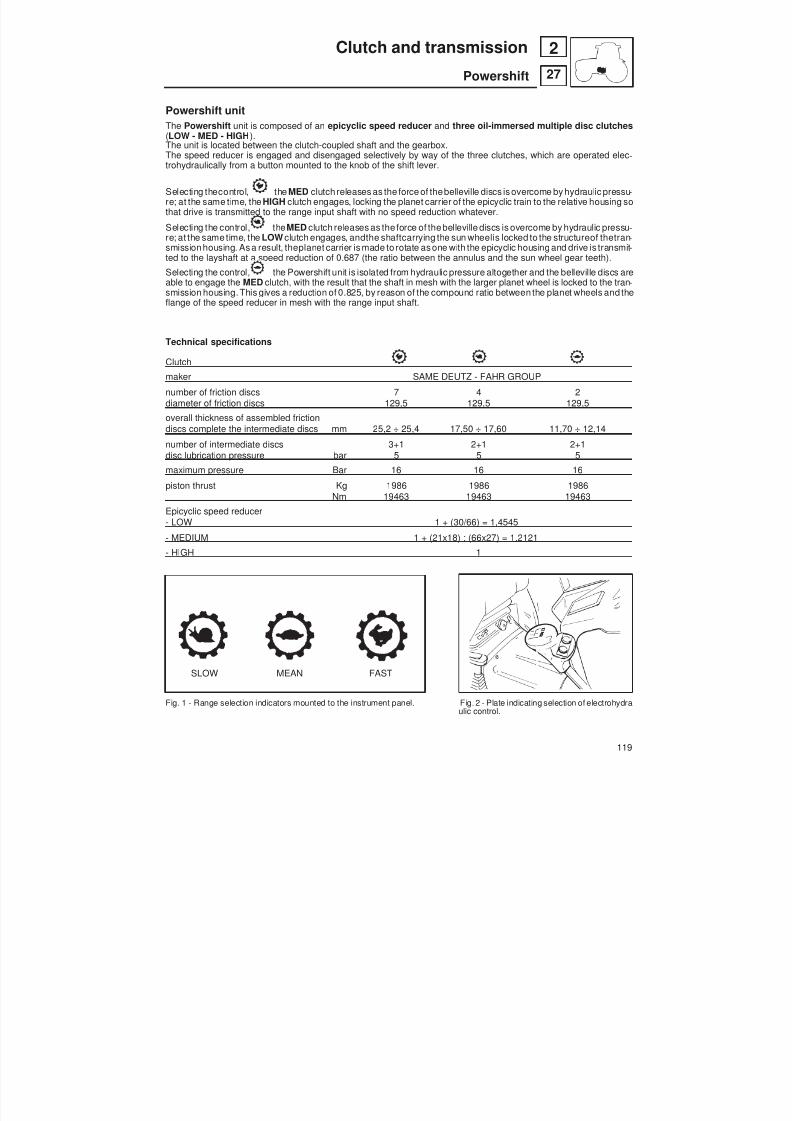
8/19/2019 Agrocompact f60 f70 f80 f90 Repair manual
http://slidepdf.com/reader/full/agrocompact-f60-f70-f80-f90-repair-manual 119/519
Powershift unitThe Powershift unit is composed of an epicyclic speed reducer and three oil-immersed multiple disc clutches(LOW - MED - HIGH ).The unit is located between the clutch-coupled shaft and the gearbox.The speed reducer is engaged and disengaged selectively by way of the three clutches, which are operated elec -trohydraulically from a button mounted to the knob of the shift lever.
Selecting thecontrol, the MED clutch releases as the force of thebelleville discs is overcome by hydraulic pressu -re; at the same time, the HIGH clutch engages, locking the planet carrier of the epicyclic train to the relative housing sothat drive is transmitted to the range input shaft with no speed reduction whatever.
Selecting the control, the MED clutch releases as the force of thebelleville discs is overcome by hydraulic pressu -re; at the same time, the LOW clutch engages, andthe shaftcarrying the sun wheelis locked to the structureof thetran -smission housing. As a result, theplanet carrier is made to rotate as one with the epicyclic housing and drive is transmit -ted to the layshaft at a speed reduction of 0.687 (the ratio between the annulus and the sun wheel gear teeth).
Selecting the control, the Powershift unit is isolated from hydraulic pressure altogether and the belleville discs areable to engage the MED clutch, with the result that the shaft in mesh with the larger planet wheel is locked to the tran -smission housing. This gives a reduction of 0.825, by reason of the compound ratio between the planet wheels and theflange of the speed reducer in mesh with the range input shaft.
Technical specifications
Clutch
maker SAME DEUTZ - FAHR GROUP
number of friction discs 7 4 2
diameter of friction discs 129,5 129,5 129,5overall thickness of assembled frictiondiscs complete the intermediate discs mm 25,2 ÷ 25,4 17,50 ÷ 17,60 11,70 ÷ 12,14
number of intermediate discs 3+1 2+1 2+1disc lubrication pressure bar 5 5 5
maximum pressure Bar 16 16 16
piston thrust Kg 1986 1986 1986Nm 19463 19463 19463
Epicyclic speed reducer- LOW 1 + (30/66) = 1,4545
- MEDIUM 1 + (21x18) : (66x27) = 1,2121
- HIGH 1
SLOW MEAN FAST
Fig. 1 - Range selection indicators mounted to the instrument panel. Fig. 2 - Plate indicating selection of electrohydra -ulic control.
119
27
2Clutch and transmission
Powershift

8/19/2019 Agrocompact f60 f70 f80 f90 Repair manual
http://slidepdf.com/reader/full/agrocompact-f60-f70-f80-f90-repair-manual 120/519
Fig. 3 - Diagram illustrating operation of the Powershift system.
Parts in movement Parts locked to transmission housing In rotation (idling)
Fig. 4 - Diagram showing engagement of Powershift with MED range selected.
120
27
2 Clutch and transmission
Powershift
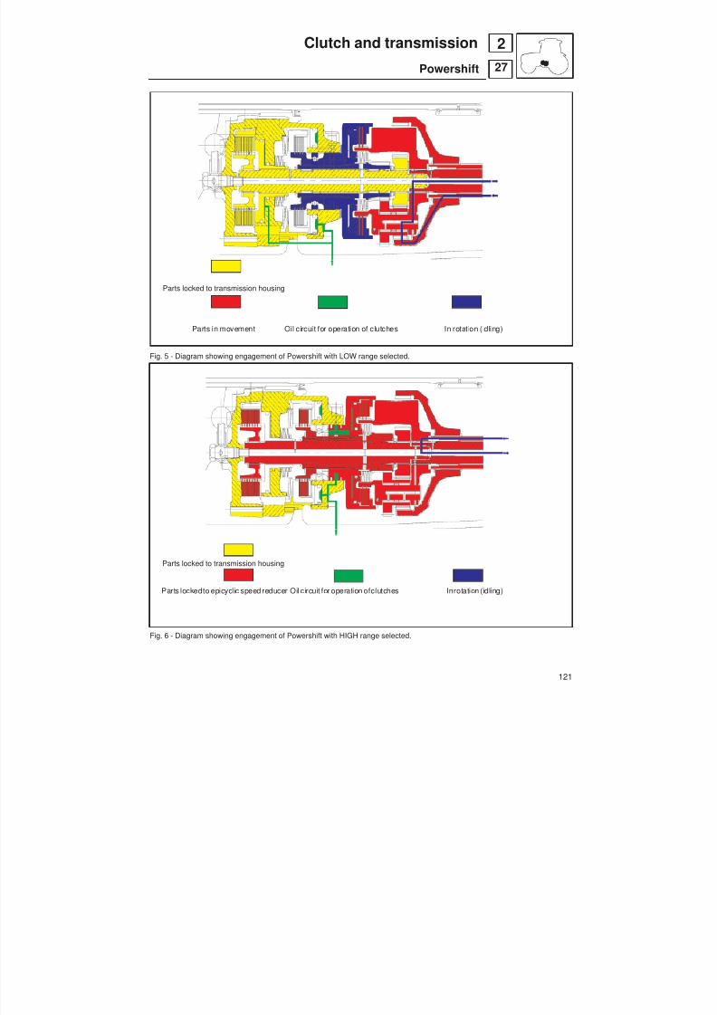
8/19/2019 Agrocompact f60 f70 f80 f90 Repair manual
http://slidepdf.com/reader/full/agrocompact-f60-f70-f80-f90-repair-manual 121/519
Parts locked to transmission housing
Parts in movement Oil circuit for operation of clutches In rotation (idling)
Fig. 5 - Diagram showing engagement of Powershift with LOW range selected.
Parts locked to transmission housing
Parts lockedto epicyclic speed reducer Oil circuit for operation ofclutches Inrotation (idling)
Fig. 6 - Diagram showing engagement of Powershift with HIGH range selected.
121
27
2Clutch and transmission
Powershift

8/19/2019 Agrocompact f60 f70 f80 f90 Repair manual
http://slidepdf.com/reader/full/agrocompact-f60-f70-f80-f90-repair-manual 122/519
POWERSHIFT UNIT DETACH FROM THE GEAR BOX
Fig. 7 - Detach the driving platform (or the cab, if fitted) fromthe tractor.
Fig. 9 - Remove the internal clutch control from the front gear -box and then remove the entire gearshift control.
Fig. 8 - Detach the front part of the tractor complete with engi -ne from the gearbox.
Fig. 10 - Remove the entire shuttle control.
122
27
2 Clutch and transmission
Powershift
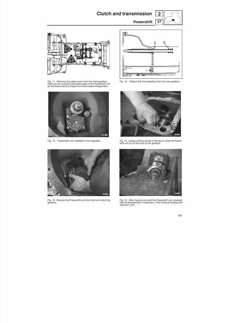
8/19/2019 Agrocompact f60 f70 f80 f90 Repair manual
http://slidepdf.com/reader/full/agrocompact-f60-f70-f80-f90-repair-manual 123/519
Fig. 11 - Remove the upper cover from the front gearbox.Remove the hydraulic lubrication pipe of the Powershift unitby first disconnecting thepart on theoutside of thegearbox.
Fig. 13 - Powershift unit installed in front gearbox.
Fig. 15 - Remove the Powershift unit from the front end of thegearbox.
Fig. 12 - Detach the front gearbox from the rear gearbox.
Fig. 14 - Using a drift as shown in the figure, drive the Power-shift unit out of the front of the gearbox.
Fig. 16 - After having removed the Powershift unit, proceedwith its disassembly, if necessary. Then remove the epicyclicreduction unit.
123
27
2Clutch and transmission
Powershift
B A

8/19/2019 Agrocompact f60 f70 f80 f90 Repair manual
http://slidepdf.com/reader/full/agrocompact-f60-f70-f80-f90-repair-manual 124/519
Fig. 17 - Remove the planet carrier flange from the epicyclicreduction unit.
Fig. 19 - The play adjustment shim for the Powershift shafts islocated between the housing and the epicyclic reduction unit.
Fig. 21 - Remove the circlip indicated in the figure using a pairof bent nose pliers.
Fig. 18 - Remove the circlip and the thrust washer. On re-as-sembly, the thrust washer must be fitted with the lubricationchannels facing inwards towards the planet carrier flange.
Fig. 20 - To dismantle the Powershift unit, remove the circlipindicated in the figure.
Fig. 22 - Remove the thrust washer.
124
27
2 Clutch and transmission
Powershift
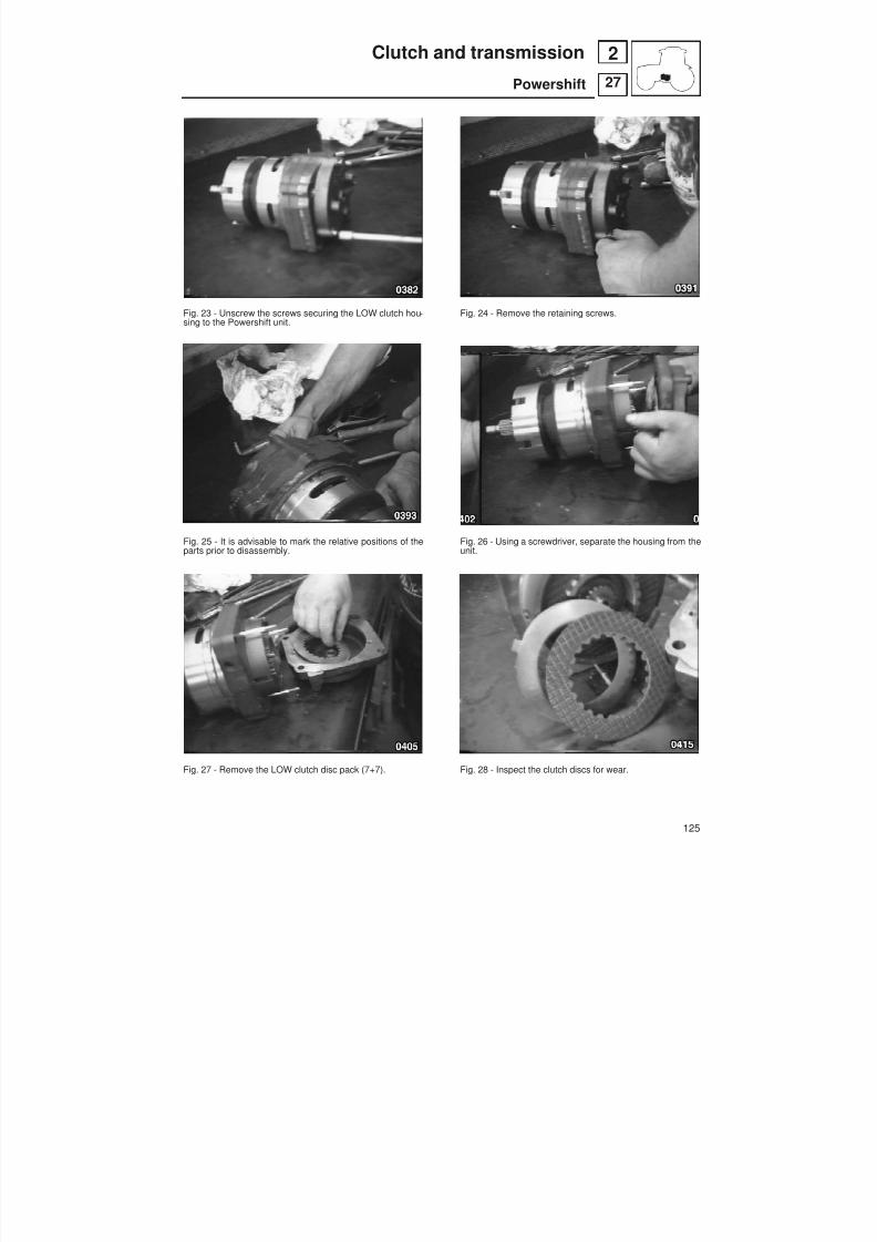
8/19/2019 Agrocompact f60 f70 f80 f90 Repair manual
http://slidepdf.com/reader/full/agrocompact-f60-f70-f80-f90-repair-manual 125/519
Fig. 23 - Unscrew the screws securing the LOW clutch hou -sing to the Powershift unit.
Fig. 25 - It is advisable to mark the relative positions of theparts prior to disassembly.
Fig. 27 - Remove the LOW clutch disc pack (7+7).
Fig. 24 - Remove the retaining screws.
Fig. 26 - Using a screwdriver, separate the housing from theunit.
Fig. 28 - Inspect the clutch discs for wear.
125
27
2Clutch and transmission
Powershift

8/19/2019 Agrocompact f60 f70 f80 f90 Repair manual
http://slidepdf.com/reader/full/agrocompact-f60-f70-f80-f90-repair-manual 126/519
Fig. 29 - Remove the circlip securing the hub of the LOWclutch.
Fig. 31 - Remove the circlip located behind the hub of theLOW clutch.
Fig. 33 - Using a drift, separate the MEDIUM-LOW housingfrom the rest of the unit.
Fig. 30 - Remove the hub of the LOW clutch.
Fig. 32 - Proceed with the disassembly of the housing of theMEDIUM-LOW clutches.
Fig. 34 - Detach the MEDIUM-LOW housing from the unit.
126
27
2 Clutch and transmission
Powershift

8/19/2019 Agrocompact f60 f70 f80 f90 Repair manual
http://slidepdf.com/reader/full/agrocompact-f60-f70-f80-f90-repair-manual 127/519
Fig. 35 - Remove the Belleville springs from the MEDIUMclutch.
Fig. 37- MEDIUM clutch discs (4 friction discs+3 counter-discs+2 thrust plates).
Fig. 39- This piston can be removed by removing the circlip ofthe piston return spring located on the opposite end of the ho -using.
Fig. 36 - Remove the discs from the MEDIUM clutch.
Fig. 38 - The control piston of the LOW clutch may be remo-ved from the “MEDIUM-LOW” bell-housing using a press ofthe type illustrated below.
Fig. 40 - Remove the LOW clutch shaft.
127
27
2Clutch and transmission
Powershift
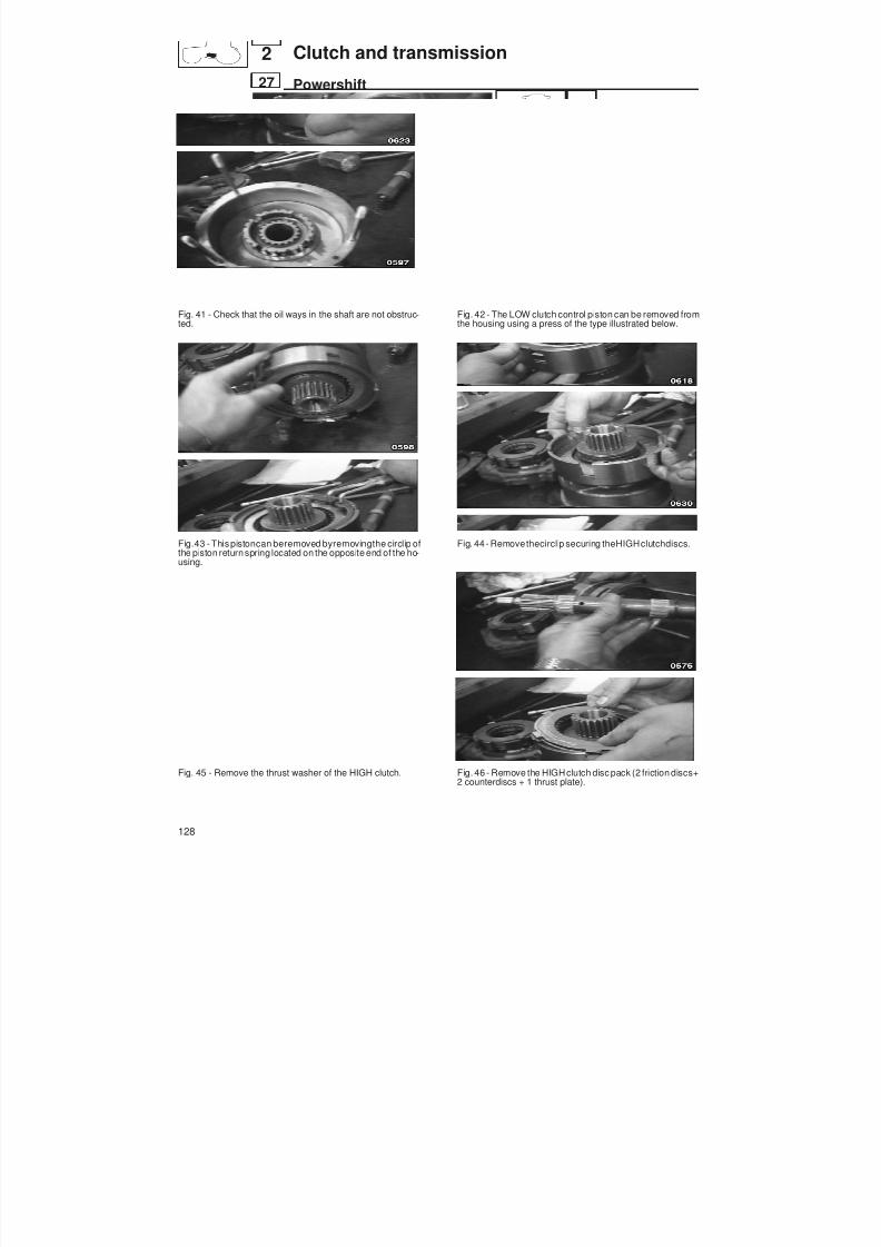
8/19/2019 Agrocompact f60 f70 f80 f90 Repair manual
http://slidepdf.com/reader/full/agrocompact-f60-f70-f80-f90-repair-manual 128/519
Fig. 41 - Check that the oil ways in the shaft are not obstruc -ted.
Fig.43 - This pistoncan beremoved byremovingthe circlip ofthe piston return spring located on the opposite end of the ho -using.
Fig. 45 - Remove the thrust washer of the HIGH clutch.
Fig. 42 - The LOW clutch control piston can be removed fromthe housing using a press of the type illustrated below.
Fig. 44 - Remove thecirclip securing theHIGHclutchdiscs.
Fig. 46 - Remove the HIGH clutch disc pack (2 friction discs+2 counterdiscs + 1 thrust plate).
128
27
2 Clutch and transmission
Powershift
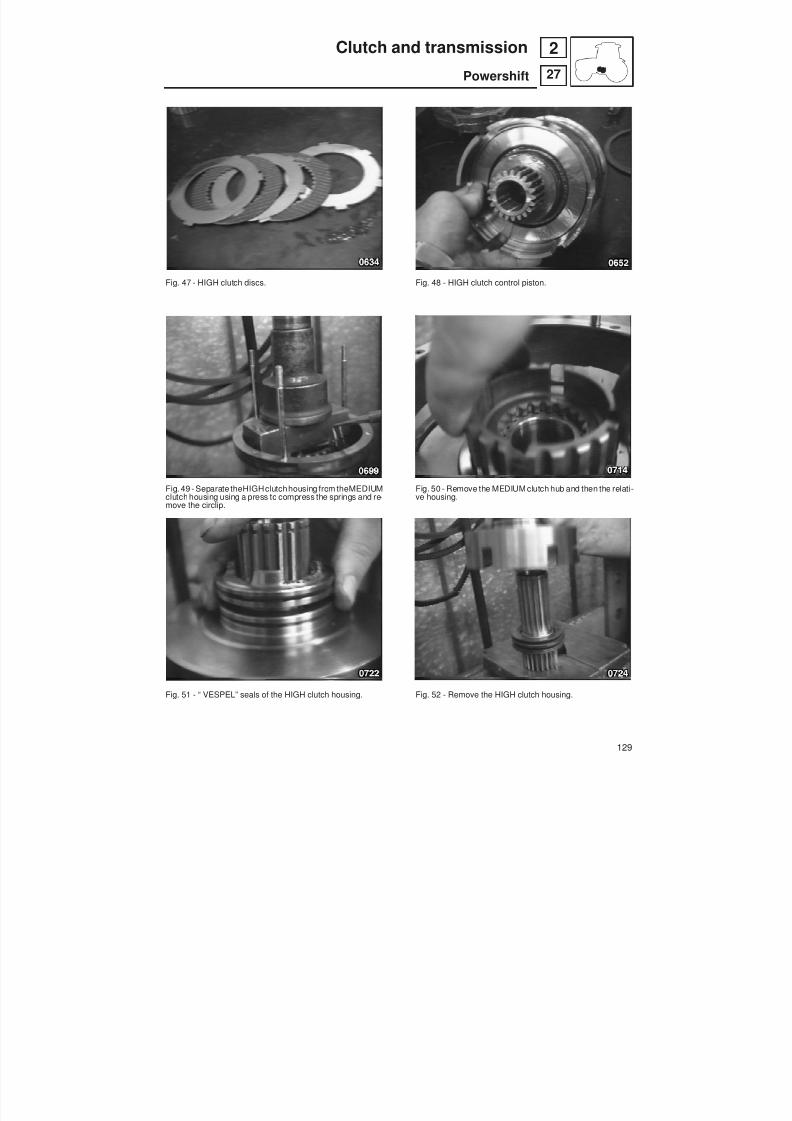
8/19/2019 Agrocompact f60 f70 f80 f90 Repair manual
http://slidepdf.com/reader/full/agrocompact-f60-f70-f80-f90-repair-manual 129/519
Fig. 47 - HIGH clutch discs.
Fig. 49 - Separate theHIGHclutchhousing from theMEDIUMclutch housing using a press to compress the springs and re -move the circlip.
Fig. 51 - “ VESPEL” seals of the HIGH clutch housing.
Fig. 48 - HIGH clutch control piston.
Fig. 50 - Remove the MEDIUM clutch hub and then the relati-ve housing.
Fig. 52 - Remove the HIGH clutch housing.
129
27
2Clutch and transmission
Powershift

8/19/2019 Agrocompact f60 f70 f80 f90 Repair manual
http://slidepdf.com/reader/full/agrocompact-f60-f70-f80-f90-repair-manual 130/519
Fig. 53 - Remove the Belleville return springs of the HIGHclutch control piston from the MEDIUM shaft.
Fig. 55 - If necessary, remove the circlip and remove the be-aring from the MEDIUM clutch housing.
Fig. 57 - Examine the condition of the seal ring of the pistonfrom the MEDIUM clutch housing.
Fig. 54 - Examine the condition of the “VESPEL” seals on theHIGH clutch housing.
Fig. 56 - Remove the piston from the MEDIUM clutch hou-sing.
Fig. 58 - Proceed to dismantle the LOW clutch control pistonwith the aid of a press.
130
27
2 Clutch and transmission
Powershift
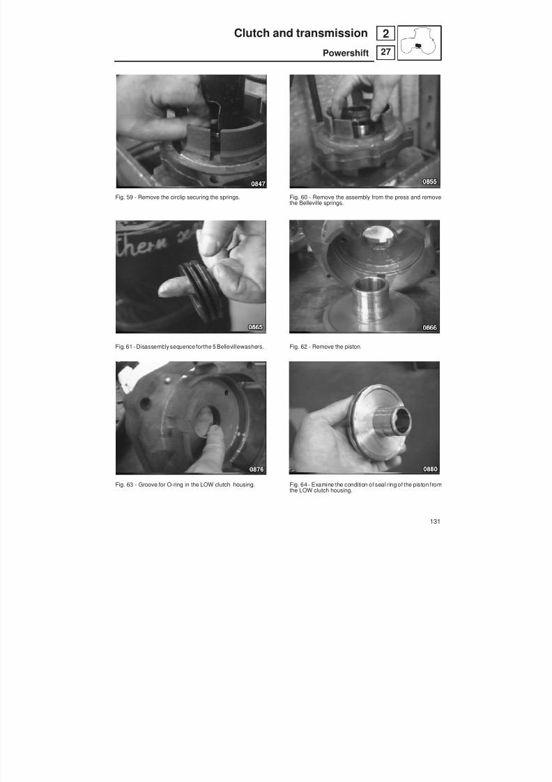
8/19/2019 Agrocompact f60 f70 f80 f90 Repair manual
http://slidepdf.com/reader/full/agrocompact-f60-f70-f80-f90-repair-manual 131/519
Fig. 59 - Remove the circlip securing the springs.
Fig. 61 - Disassembly sequence forthe 5 Bellevillewashers.
Fig. 63 - Groove for O-ring in the LOW clutch housing.
Fig. 60 - Remove the assembly from the press and removethe Belleville springs.
Fig. 62 - Remove the piston.
Fig. 64 - Examine the condition of seal ring of the piston fromthe LOW clutch housing.
131
27
2Clutch and transmission
Powershift

8/19/2019 Agrocompact f60 f70 f80 f90 Repair manual
http://slidepdf.com/reader/full/agrocompact-f60-f70-f80-f90-repair-manual 132/519
A - Cover I - Seeger T - LOW sun wheelB - LOW clutch L - Clutch hub U - Planet carrierC - LOW clutch control piston M - Thrust plate V - Thrust washerD - Clutch housing N - Bearing Z - Ring gear
MEDIUM - LOW O - Thrust plate X - Planet gearsE - LOW clutch belleville springs P - MEDIUM clutch control piston J - LOW shaftF - MEDIUM clutch belleville springs Q - HIGH clutch housing Y - MEDIUM shaftG - Actuator disc R - HIGH clutch control piston W - Secondary shaftH - MEDIUM clutch S - HIGH clutch K - Reduction unit shaft
Fig. 65 - Powershift unit
132
27
2 Clutch and transmission
Powershift
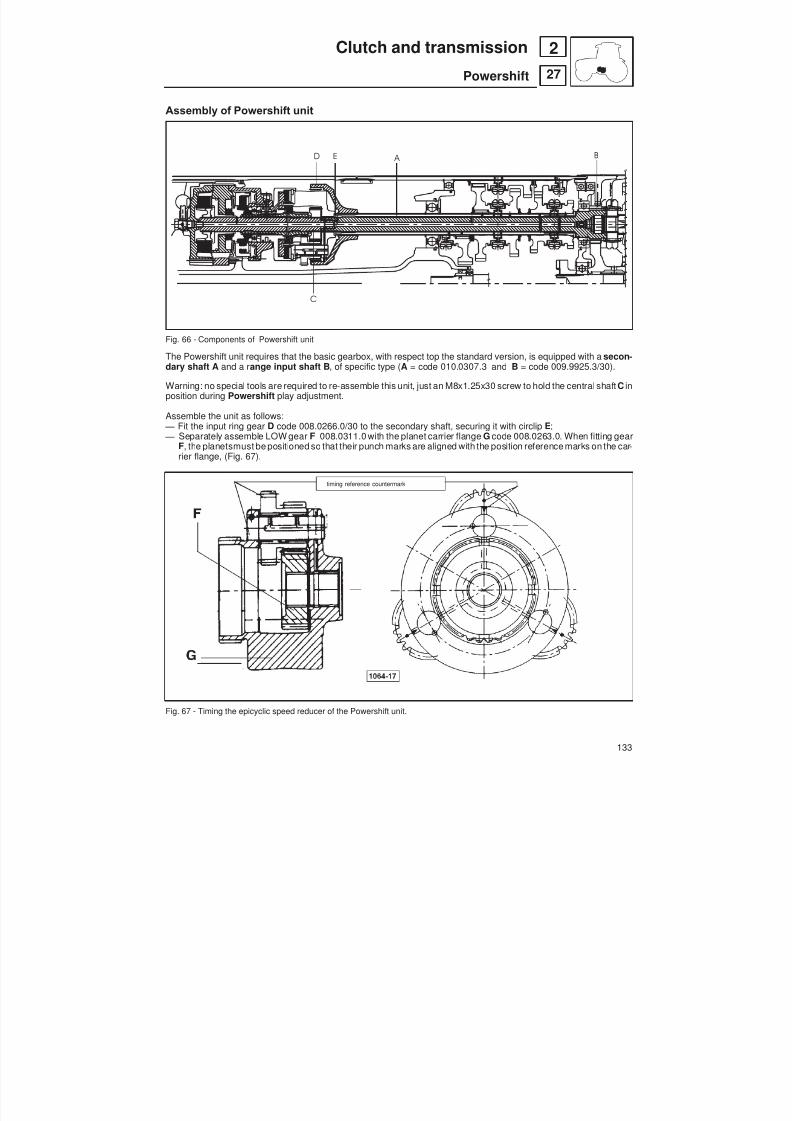
8/19/2019 Agrocompact f60 f70 f80 f90 Repair manual
http://slidepdf.com/reader/full/agrocompact-f60-f70-f80-f90-repair-manual 133/519
D E A
C
B
Assembly of Powershift unit
Fig. 66 - Components of Powershift unit
The Powershift unit requires that the basic gearbox, with respect top the standard version, is equipped with a secon -dary shaft A and a r ange input shaft B , of specific type ( A = code 010.0307.3 and B = code 009.9925.3/30).
Warning: no special tools are required to re-assemble this unit, just an M8x1.25x30 screw to hold the central shaft C inposition during Powershift play adjustment.
Assemble the unit as follows:— Fit the input ring gear D code 008.0266.0/30 to the secondary shaft, securing it with circlip E;— Separately assemble LOW gear F 008.0311.0 with the planet carrier flange G code 008.0263.0. When fitting gear
F, the planetsmust be positioned so that their punch marks are aligned with the position reference marks on the car -rier flange, (Fig. 67).
timing reference countermark
Fig. 67 - Timing the epicyclic speed reducer of the Powershift unit.
133
27
2Clutch and transmission
Powershift
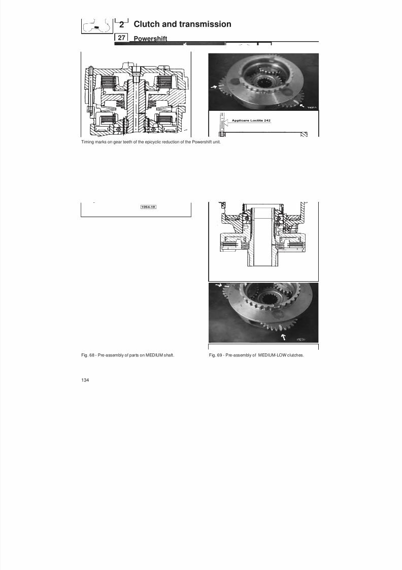
8/19/2019 Agrocompact f60 f70 f80 f90 Repair manual
http://slidepdf.com/reader/full/agrocompact-f60-f70-f80-f90-repair-manual 134/519
Timing marks on gear teeth of the epicyclic reduction of the Powershift unit.
Fig. 68 - Pre-assembly of parts on MEDIUM shaft. Fig. 69 - Pre-assembly of MEDIUM-LOW clutches.
134
27
2 Clutch and transmission
Powershift
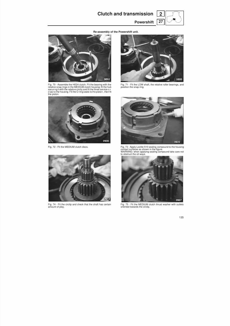
8/19/2019 Agrocompact f60 f70 f80 f90 Repair manual
http://slidepdf.com/reader/full/agrocompact-f60-f70-f80-f90-repair-manual 135/519
Re-assembly of the Powershift unit.
Fig. 70 - Assemble the HIGH clutch. Fit the bearing with therelative snap rings in the MEDIUM clutch housing; fit the hubsecuring it with the relative circlip and fit the three service cir -clips to the housing. Fit the O-ring seals to the piston , then fitthe piston.
Fig. 72 - Fit the MEDIUM clutch discs.
Fig. 74 - Fit the circlip and check that the shaft has certainamount of play.
Fig. 71 - Fit the LOW shaft, the relative roller bearings, andposition the snap ring.
Fig. 73 - Apply Loctite 510 sealing compound to the housingcontact surfaces as shown in the figure.WARNING: when applying sealing compound take care notto obstruct the oil ways.
Fig. 75 - Fit the MEDIUM clutch thrust washer with outletsoriented towards the circlip.
135
27
2Clutch and transmission
Powershift

8/19/2019 Agrocompact f60 f70 f80 f90 Repair manual
http://slidepdf.com/reader/full/agrocompact-f60-f70-f80-f90-repair-manual 136/519
Fig. 76 - Join the two housings together; the studs will locatein the 3 holes to ensure the correct relative positions of thetwo housings. Rotate the shaft during this operation so as tocentre the clutch discs.
Fig. 78 - Fit the LOW clutch, first positioning the circlip on theshaft as indicated in the figure.
Fig. 80 - Then install the discs of the LOW clutch.
Fig. 77 - Note that a small space will be left between the twohousings; this is to allow preloading of the Belleville springswhen the screws are tightened.
Fig. 79 - Then fit the clutch hub and position the second cir -clip.
Fig. 81 - The disc pack is completed with a final friction disc,the tabs of which do not engage the splines on the hub, andtherefore, when refitting the cover, it is advisable not to rotatethe shaft soas to allow the disc tabs tomeshcorrectly withthehub.
136
27
2 Clutch and transmission
Powershift

8/19/2019 Agrocompact f60 f70 f80 f90 Repair manual
http://slidepdf.com/reader/full/agrocompact-f60-f70-f80-f90-repair-manual 137/519
ADJUSTMENT OF END FLOAT IN THE POWERSHIFT UNIT (fig. 82)
Screw one M8x1,25x30 bolt finger tight into the cover W (fig82), soas to hold the centre shaft of the H-M-L unit inposi -tion during the adjustment.
Measuredimensions X and Y with a gauge then calculate (X-Y-1mm) , which gives the thickness of the thrust washerK to fit.
Example: values measured X = 191,88 Y = 188,24
(191,88 - 188,24 - 1) = 2,64~ 2,6mm (2.1599.727.0/10 washer required is p/n2.1599.729.0/10)
IMPORTANT : the thrust washer must be selected from those available to give either the exact thickness, or the nextthickness down from the value calculated.washer p/n:
2.1599.725.0/10 thickness 2.2 mm
2.1599.726.0/10 thickness 2.4 mm2.1599.727.0/10 thickness 2.6 mm2.1599.728.0/10 thickness 2.8 mm2.1599.729.0/10 thickness 3 mm2.1599.730.0/10 thickness 3.2 mm2.1599.731.0/10 thickness 3.4 mm2.1599.732.0/10 thickness 3.6 mm2.1599.733.0/10 thickness 3.8 mm2.1599.734.0/10 thickness 4 mm
— Fit a shim of the predetermined thickness on the LOW shaft with the relative circlip— Fit the epicyclic reduction unit in the gearbox and then fit the Powershift clutchesunit, applying Silastic sealing com -
pound to the contact surfaces.
Fig. 82 - Location of the preassembled Powershift unit in its housing.
137
27
2Clutch and transmission
Powershift

8/19/2019 Agrocompact f60 f70 f80 f90 Repair manual
http://slidepdf.com/reader/full/agrocompact-f60-f70-f80-f90-repair-manual 138/519
Fitting the oil manifolds of the Powershift unit
Fit the manifolds in their respective seats so that they protrude 12 mm relative to the upper face of the gearbox, as indicated in the fi -gure.
Hydraulic control circuit (version without hydraulic shuttle).
138
27
2 Clutch and transmission
Powershift
H
M
L
P
T
A
A
T
P
Lubrif.
Lubrificaz.
Alimentaz.
High
Low
Medium

8/19/2019 Agrocompact f60 f70 f80 f90 Repair manual
http://slidepdf.com/reader/full/agrocompact-f60-f70-f80-f90-repair-manual 139/519
A
P T
A
P T
H M L
P T
A A
I n n
.
D i s
.
Front
Diff.look
Rear D i s
.
I n n
.
4 Wd
TP
V max V max V max13.9 cm14.7 cm11.6 cm 3 3 3
ø 1 Lf
5 bar 16 bar
P.T.O.
A
P T
11 bar
27 L/min.
150 Micr.
3 2 c c
ø 1.1
Main shaft
Sec. shaft
11 cm
x
15 Micr.
2.4419.480.0
GUIDA IDROSTATICA
A B
C
D
E
F
G
H
I
N
T
RS
LP Q O
M1
M1 M2
1 1
2 2
A pressure regulator valve N hydrostatic steering(operating pressure 16 bar) O 4-wheel drive
B gearbox lubrication oil 1 - disengagedpressure setting valve 2 - engaged(setting 5 bar) P front differential lock
C anticavitation valve for safety 1 - disengagedsteering (30 l/min.) 2 - engaged
D oil pump (capacity 10 to 27 l/min.) Q rear differential lockE suction filter 1 - disengagedF solenoid control valves 2 - engagedG electro-hydraulic control unit R P.T.O.H anticavitation valve for safety steering S primary shaftI bistable valve T lubricationL secondary shaft
M1 pressure gauge with scale 0 ÷ 40 barM2 pressure gauge with scale 0 ÷ 10 bar
Fig. 83 - Hydraulic diagram illustrating operation.
139
27
2Clutch and transmission
Powershift
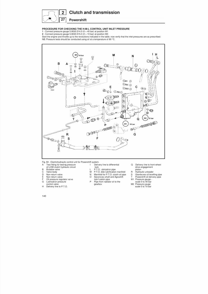
8/19/2019 Agrocompact f60 f70 f80 f90 Repair manual
http://slidepdf.com/reader/full/agrocompact-f60-f70-f80-f90-repair-manual 140/519
PROCEDURE FOR CHECKING THE H-M-L CONTROL UNIT INLET PRESSURE1 - Connect pressure gauge 5.9030.514.0 (0 ÷ 40 bar) at position M1.2 - Connect pressure gauge 5.9030.515.0 (0 ÷ 10 bar) at position M2.Start the engine and throttle up to the revolutions indicated in the table; now verify that the inlet pressures are as prescribed.NB: Pressure tests should be conducted using oil at a temperature of 80 °C.
Fig. 84 - Electrohydraulic control unit for Powershift system.A Test fitting for testing pressure I Delivery line to differential Q Delivery l ine to front-wheel
of LOW clutch hydraulic circuit lock drive engagementB Bistable valve L P.T.O. lubrication pipe pistonC Valve body M P.T.O. disk lubrification manifold R Hydraulic unloaderD Non-return valve N Manifold for P.T.O. clutch oil pipe S Gearboxes oil levelling pipeE Non-return valve O Secondary shaft and Agroshift T Powershift oil delivery pipeF Oil pressure regulator valve lubrification pipe M1 Pressure gauge -G Lubrication pressure P Pipe from radiator oil to the scale 0 to 40 bar
control valve gearbox M2 Pressure gaugeH Delivery line to P.T.O. scale 0 to 10 bar
140
27
2 Clutch and transmission
Powershift
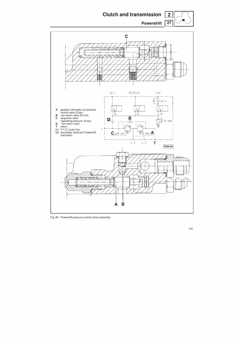
8/19/2019 Agrocompact f60 f70 f80 f90 Repair manual
http://slidepdf.com/reader/full/agrocompact-f60-f70-f80-f90-repair-manual 141/519
A gearbox lubrication oil pressurecontrol valve (5 bar)
B non-return valve 30 l/minC sequence valve
(operating pressure 16 bar)
D non-return valveT returnL1 P.T.O. clutch lineL2 secondary shaft and Powershift
lubrication
Fig. 85 - Powershift pressure control valves assembly
141
27
2Clutch and transmission
Powershift

8/19/2019 Agrocompact f60 f70 f80 f90 Repair manual
http://slidepdf.com/reader/full/agrocompact-f60-f70-f80-f90-repair-manual 142/519
clutch slips
clutch won’tdisengage
check the clutchassembly hydraulicsystem
check piston forfree stroke
check the clutch
plates for wear
inspect the controlmechanism
inspect the disks
piston jammed inseat
replace the defecti -ve parts
examine piston andmanifold seal rings
remove any roug -hness preventingpiston from slidingfreely
replace the clutch
disks
replace defectiveparts
burnt disks
relpace the piston
replacedefective parts
replace the disks
jammed disksremove any roug -hness preventingdisks from slidingfreely
142
2 Clutch and transmission
Diagnosing malfunctions

8/19/2019 Agrocompact f60 f70 f80 f90 Repair manual
http://slidepdf.com/reader/full/agrocompact-f60-f70-f80-f90-repair-manual 143/519
General specificationsThe basic transmission utilizes 5 speed synchromesh gearbox with 2 or 3 speed ranges.
A shuttle, fitted as standard, makes the tractor easy to handle and manoeuvre.
Options include Creeper, and Underdrive (in place of or in addition), giving a total of:
For tractors equipped with driving position with footplates only16 FWD + 8 REV: 4 gears x 2 ranges + mini-reduction + reverser shuttle24 FWD + 12 REV: 4 gears x 3 ranges + mini-reduction + reverser shuttle
For tractors equipped with platform or cab20 FWD + 10 REV: 5 gears x 2 ranges (L-V) + mini-reduction + reverser shuttle30 FWD + 15 REV: 5 gears x 3 ranges (SR-L-V) + mini-reduction + reverser shuttle.
45 FWD + 45 REV: 5 gears x 3 ranges (SR-L-V) + reverser shuttle + POWERSHIFT
Each version is also available with 30 or 40 km/h top speed.
Technical specifications
number of speeds 16 AV + 8 RM 20 AV + 10 RM
gearbox ratios1st gear 19/59 = 1/3,1053 19/59 = 1/3,1053
2nd gear 24/47 = 1/1,9583 23/50 = 1/2,17393rd gear 34/42 = 1/1,2353 29/44 = 1/1,5172
4th gear 41/32 = 1/0,7805 35/38 = 1/1,08575th gear - 42/30 = 1/0,7143
shuttle: forward 29/37 = 1/0,7838reverse 23/19 = 1/0,8261
range ratios: low (19/50)x(22/46)= 1/5,5024high 1
rear axle ratiosbevel gear pair 30 km/h 8/36 = 1/4,5000 -
40 km/h 12/45 = 1/3,7500 12/45 = 1/3,7500- with tyres 380/79R20 and 240/70R16 30 km/h - -- with tyres 380/79R20 and 240/70R16 40 km/h 9/32 = 1/3,5556 9/32 = 1/3,5556
epicyclic final drive (12/12+69) = 1/6,7500overall ratio 30 km/h 1/30,3750 -
40 kmIh 1/25,3125 1/25,3125
backlash between crownwheeland pinion teeth mm 0,18 - 0,24
Mini-reduction 32/34 = 1/0,9412
Super-reduction (19/50)x(22/46)x(19/50)x(20/48) = 1/34,7520
axial play of the secondary shaft mm 0,09axial play of the gears of the change,of the reverser and mini-reduction mm 0,15 ÷ 0,30
reference distance for adjustmentof bevel gear pair mm 2,5 ± 0,1
143
31
3Transmission
Gearbox

8/19/2019 Agrocompact f60 f70 f80 f90 Repair manual
http://slidepdf.com/reader/full/agrocompact-f60-f70-f80-f90-repair-manual 144/519
Speed change configurations
Speed range Gearshifting Reversing NO. OF SPEEDControl Control Control (forward + reverse)
16 + 8
24 + 12
20 + 10
30 + 15
45 + 45
DURING TRANSPORT OPERATIONS ON PUBLIC ROADS BOTH BRAKE PEDALS MUST BE
OBLIGATORILY COUPLED BY MEANS OF THE SPECIAL LOCKING LATCH. IN ANY CASE,ALWAYS OBSERVE LAWS AND REGULATIONS IN FORCE.
144
31
3 Transmission
Gearbox

8/19/2019 Agrocompact f60 f70 f80 f90 Repair manual
http://slidepdf.com/reader/full/agrocompact-f60-f70-f80-f90-repair-manual 145/519
* see technical characteristics of gearbox on p. 143 * see technical characteristics of gearbox on p. 143** see technical characteristics of 4wd front axle on p. 217 ** see technical characteristics of 4wd front axle on p
Fig. 1 - Ratios of 4-speed x 2 range transmission with mini-reduction (16 FWD + 8 REV). Ratios of 4-speed x 2 range transmission with mini-reduction

8/19/2019 Agrocompact f60 f70 f80 f90 Repair manual
http://slidepdf.com/reader/full/agrocompact-f60-f70-f80-f90-repair-manual 146/519
* see technical characteristics of gearbox on p. 139 * see technical characteristics of gearbox on p. 143** see technical characteristics of 4wd front axle on p. 217 ** see technical characteristics of 4wd front axle on p. 209
Fig. 2 - Ratios of 5-speed x 2 range transmission with mini-reduction (20 FWD + 10 REV). Ratios of 5-speed x 2 range transmission with mini-reduction and
146
Transmission
Gearbox
331
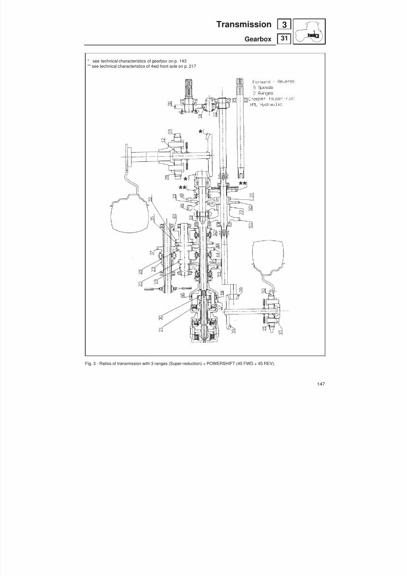
8/19/2019 Agrocompact f60 f70 f80 f90 Repair manual
http://slidepdf.com/reader/full/agrocompact-f60-f70-f80-f90-repair-manual 147/519
* see technical characteristics of gearbox on p. 143** see technical characteristics of 4wd front axle on p. 217
Fig. 3 - Ratios of transmission with 3 ranges (Super-reduction) + POWERSHIFT (45 FWD + 45 REV).
147
31
3Transmission
Gearbox

8/19/2019 Agrocompact f60 f70 f80 f90 Repair manual
http://slidepdf.com/reader/full/agrocompact-f60-f70-f80-f90-repair-manual 148/519
Assemble the front and rear gearboxes and the rear hydraulic lift,after having applied PIANERMETIC 510 to surfaces Aand LOCTITE 636 to bushes B .
Fig. 4 - Front and rear gearbox.
148
31
3 Transmission
Gearbox
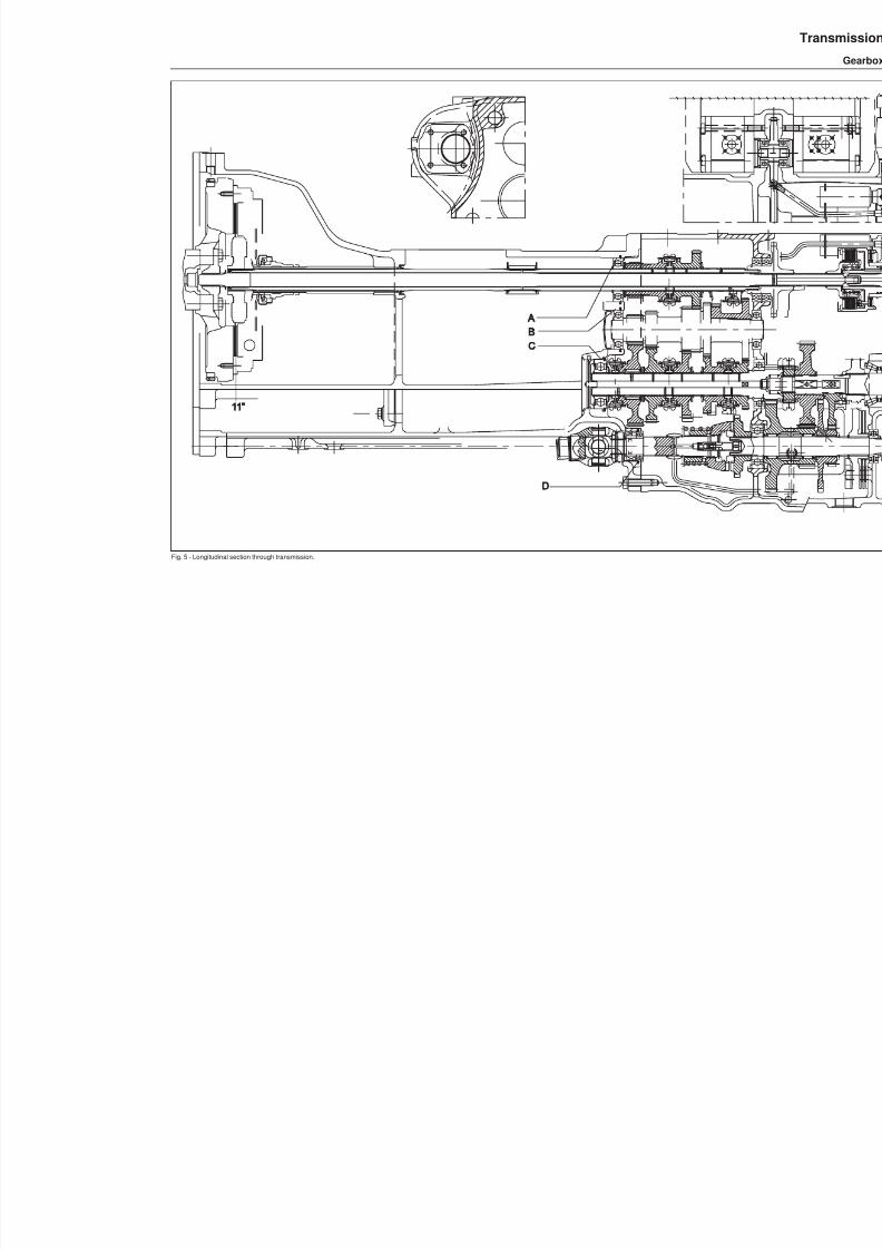
8/19/2019 Agrocompact f60 f70 f80 f90 Repair manual
http://slidepdf.com/reader/full/agrocompact-f60-f70-f80-f90-repair-manual 149/519
Fig. 5 - Longitudinal section through transmission.
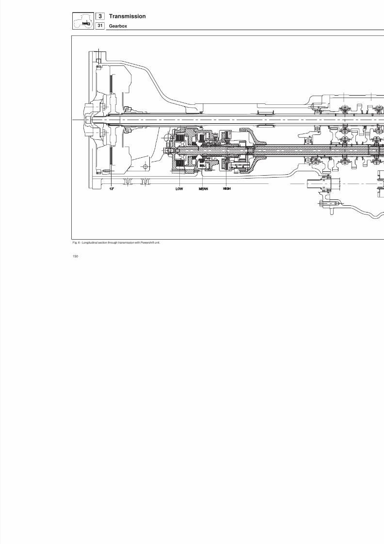
8/19/2019 Agrocompact f60 f70 f80 f90 Repair manual
http://slidepdf.com/reader/full/agrocompact-f60-f70-f80-f90-repair-manual 150/519
Fig. 6 - Longitudinal section through transmission with Powershift unit.
150
Transmission
Gearbox
331
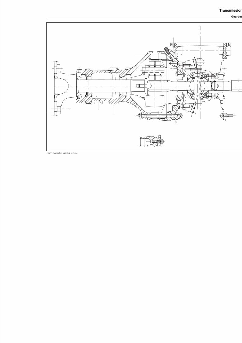
8/19/2019 Agrocompact f60 f70 f80 f90 Repair manual
http://slidepdf.com/reader/full/agrocompact-f60-f70-f80-f90-repair-manual 151/519
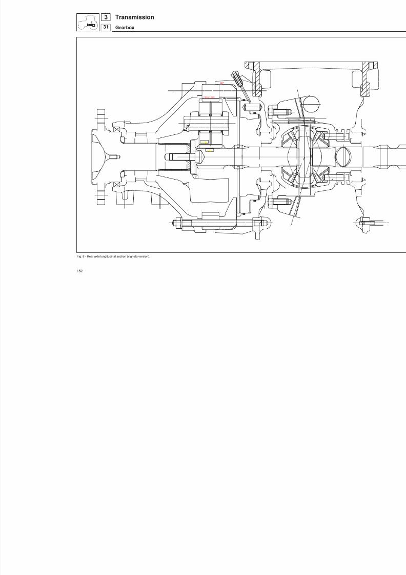
8/19/2019 Agrocompact f60 f70 f80 f90 Repair manual
http://slidepdf.com/reader/full/agrocompact-f60-f70-f80-f90-repair-manual 152/519
Fig. 8 - Rear axle longitudinal section (vigneto version).
152
Transmission
Gearbox
331
z 69-m 3.25
H7
z 28
z 12
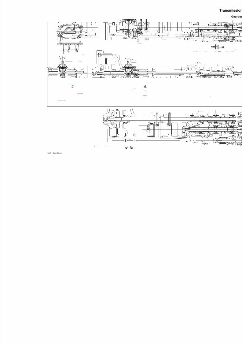
8/19/2019 Agrocompact f60 f70 f80 f90 Repair manual
http://slidepdf.com/reader/full/agrocompact-f60-f70-f80-f90-repair-manual 153/519
Fig. 9 - Gear lever.
L U B R I F .
L O W
M E D I U M / H I G H
LOCTITE 638
INGOMBRO MAX. FORCELLA
INVERSORE
CAMBIO
77796.0
5 9
. 5
C
8 °1 5'
7 °5 6 '
(10° 1 ') (9°33' )
8 ° 2 3 ' ( 1 0
8 ° 1 3 ' )
8 ° 7 ' ( 9 8 ° 4 8 ' )
ø140 g7
77100.0

8/19/2019 Agrocompact f60 f70 f80 f90 Repair manual
http://slidepdf.com/reader/full/agrocompact-f60-f70-f80-f90-repair-manual 154/519
Fig. 10 - Views of the gearbox.
154
Transmission
Gearbox
331
I N V E R S O R E
M I N I
I N V E R S O R E
M I N I
Asse motoreEngine axle
1°3°/43°4°/54°2°/32°
1°/21°
s m o n t a g g i o
SAUER 11 cc
L-VSR
L-SR V
LATO DESTRO
LATO DESTRO
LATO DESTRO
CAMBIOINVERSORE
RIDUTTORERIDUTTORESez.
Section
B-B
Sez.Section
A-A
1 0 7 °
+ 4 0 '
0
6 ° 5 5 ' ( 7 6 ° 2 2 ' )
2
220 MINIMO VIGNETO
6 ° 2 6 '10°24 '(1210 °29' )
1 0 ° 2 4 ' ( 1 2 1 0 ° 2 9 ' )
8.5 ±0.05
6 ° 5 3 '
6 ° 5 3 '
L-SR V
SR
C
s m o n t a g g i o
SAUER 11 cc
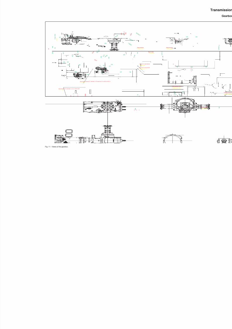
8/19/2019 Agrocompact f60 f70 f80 f90 Repair manual
http://slidepdf.com/reader/full/agrocompact-f60-f70-f80-f90-repair-manual 155/519
Fig. 11 - Views of the gearbox.
Vista parziale da BPartial view from
D
D
M
A R
1
3 2
5 4
2 1
4 3
C A M B I O
I N V E R S O R E
I
R I D U T T O R E
L V S R
M18x1.5
1 6 ° 5
4 '
8525165
238182232
1 0 5
2 1 5
3 2 5
3 7 4
4 3 5 142
1 3 5
24 74
4 f o r i M 1 4
162
192
25
h o l e s
2 fori ø13holes
3 fori ø15holes
2 spine ø12 B8
dowels
8 ° 5 7 '
8 ° 5 7
'
8 ° 6 '
Albero presa di potenza D.T. ANSI B92.1-1970 øe28.28 Z17 m1.5875/0.79375 c.f.4 W.D. shaft
124211
414
1 4 8
1 8 3
6 8
. 5
1 ° 2 8 ' 5 2 "
4 ° 3 2 ' 3 0 "
2 0 ° 2 9 ' 2 7 "
1 2 ° 1 6
' 5 3 "
F O L L E
5 4 0 7
5 0
1 0 0 0
2 6 5
116583 317
Asse motoreEngine axle
Albero entrata P.T.O. ANSI B92.1 z:14 m:1.5875/0.79375P.T.O. shaft.
Albero frizione cambio ANSI B92.1 z:24 m:1.5875/0.79375Trasmission shaft
409
1 1 3
. 5
PIK UP
62470
1114
2225
ø 1 5 2
. 4
6 2 4
7 0
7 0
8 ° 1 5 '
7 ° 5 6 '
679
1262
2 0
1 2 5
1 4 8
20 6 f o r i M 1 6
h o
l e s
332 190
2 0 7
2 9 2
1 0 5
120 60
1 4 0
1 0 ° 5 ° 3 '
Asse ruotaWheel axle
B
Albero P.T.O. 540/750/1000Power take-off
Albero P.T.O. sincronizzataGround speed P.T.O.
3 5
5 8
201
243
= =
Asse motoreEngine axle
= =
= =
= =
5 1 6
= =

8/19/2019 Agrocompact f60 f70 f80 f90 Repair manual
http://slidepdf.com/reader/full/agrocompact-f60-f70-f80-f90-repair-manual 156/519
Fig. 12 - Views of the gearbox.
156
Transmission
Gearbox
331
C
I
Engine axle Asse motore
4 fori M12
4 f o r i
M 1 6
8282
2 2 0
208
holes
h o l e s
158
2 f o r i
M 1 6
28
35
h o l e s
6 ° 5 5 '
6 ° 3 8 '
6 ° 3 8 '
118118
2 f o r i
M 1 6
8 f o r i
M 1 2
h o l e s h o
l e s
Sez.Section
E-E Sez.Section
H-H
C
R
7 ° 5 0 '
7 ° 3 5 '
1 0 ° 2 4 '
1 0 ° 2 4 '
45185
1 9 7
A
E
E
H
H
G
G
K
K

8/19/2019 Agrocompact f60 f70 f80 f90 Repair manual
http://slidepdf.com/reader/full/agrocompact-f60-f70-f80-f90-repair-manual 157/519
Fig. 13 - Electro - hydraulic control for front-wheel drive engagement/disengagement.
Asse ruota
97080.2
4 marce
COMANDO D.T. A FRIZIONE
DIN 5480 35x2x16 c.e.
4 marce
4 marce
VERSIONE RISAIA
VERSIONE STANDARD
14.9
15.2
15.5
15.8
( )
( )
( )
( )
ø
0 . 4
M 1 6 x 1
. 5
1.95/2.87
0.74/1.99
4
57 +0.20
47.6 +0.20
1.5 -0.06
10 ±0.1
8 2.5 0
-0.06
2/2.96
17.2
1.6 ±0.05
2.2 ±0.05
60.65
1.1 0-0.06
7.5 0-0.1
0.010.9881.00.010.9882.00.010.9883.0
0.010.9884.0

8/19/2019 Agrocompact f60 f70 f80 f90 Repair manual
http://slidepdf.com/reader/full/agrocompact-f60-f70-f80-f90-repair-manual 158/519
Fig. 14 - Gear selector rod. A - bolts securing hubs to rod. Fig. 15 - Gear selector rod. B - C - bolts securing hubs to rod
158
Transmission
Gearbox
331
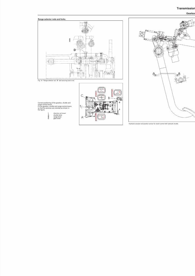
8/19/2019 Agrocompact f60 f70 f80 f90 Repair manual
http://slidepdf.com/reader/full/agrocompact-f60-f70-f80-f90-repair-manual 159/519
Range selector rods and forks.
Fig. 16 - Range selector rod. D - bolt securing hub to rod.
Correct positioning of the gearbox, shuttle andrange control levers.Fit the gearbox, shuttle and range control leversso that the grooves are oriented as shown inthe figure.
1 direction of travelA shuttle leverB range leverC gear lever
Hydraulic actuator and position sensor for clutch control with h
M
A R
1
3 2
5 4
2 1
4 3
C A M B I O
I N V E R S O R E
R I D U T T O R E
L V
S R
1
BC
A

8/19/2019 Agrocompact f60 f70 f80 f90 Repair manual
http://slidepdf.com/reader/full/agrocompact-f60-f70-f80-f90-repair-manual 160/519
Hydraulic shuttle control.
160
Transmission
Gearbox
331
Posizionassenza (recupe
A-R
1° 2°-3°
C
LOCTITE 638
CAMBIO
A 1 2 1
intervallo corrispondente alla fase di incertezzadel sensore, (contatto aperto-contatto chiuso)
Da 4.67 a 6.4:
L O W
M E D I U M / H I G H
Sez.Section
A-A
Inversore
A-R
il sensore puo' indicare "innesto marcia avvenuto"
Ø 2 0 f 7 /
+ 0
. 1 2 0
+ 0
. 0 9 0
6.4 corsa
2
6
2
5
4.67 Corsa
Contatto chiuso/aperto
il contatto inizia ad aprire/chiuderesegnando la posizione di folle
2.6
26
70.8 ±0.15
4 0 ± 0 . 1
24 ±0.2
52±0.1
27
22 ±0.125
52 ±0.15

8/19/2019 Agrocompact f60 f70 f80 f90 Repair manual
http://slidepdf.com/reader/full/agrocompact-f60-f70-f80-f90-repair-manual 161/519

8/19/2019 Agrocompact f60 f70 f80 f90 Repair manual
http://slidepdf.com/reader/full/agrocompact-f60-f70-f80-f90-repair-manual 162/519

8/19/2019 Agrocompact f60 f70 f80 f90 Repair manual
http://slidepdf.com/reader/full/agrocompact-f60-f70-f80-f90-repair-manual 163/519
Removal of the gear train positioned in the front gearbox
WARNING: On tractors equipped with Powershift, first follow the instructions to remove the Powershiftunit and the ge-arbox input and P.T.O. shafts.For the following operations the driving platform or cab must be removed in order to gain access to the upper gearboxcover.
Before proceeding with the removal of the gear train, it is necessary to remove the selector rods and forks. Theseoperations are only possible after having separated the rear gearbox from the front; before separating the twogearboxes, remove D fig. 5 on page149.Detach the front gearbox from the rear gearbox. To do this, it will be necessary to remove the 5 speedrelay hub togetherwith the intermediate support, located on the right-hand side of the rear gearbox. Remove screw A (fig. 14) screws B(fig. 15) and screw D (fig. 16).
NB: Remove the selector rod detent balls and springs by unscrewing the relative plugslocatedon the right-hand side ofthe gearbox. Then proceed with the separation of the two gearboxes.The 3 gearbox shafts (inversor, primary and secondary) and the gear selector and inversor control rods and forks willremain attached to the front gearbox. To remove these rods, it will first be necessary to remove the 3 shafts by removingthe 3 circlips A - B - C fig. 5 on page 149 andthen moving all 3 shafts simultaneously backwards to disengage them fromtheir housings; the first shaft to be detached willbe the primary shaft, followed by thesecondary, and then theinput shaftlocatedat theuppermost part of the gearbox is to be withdrawn. Eachselector rodwillcomeaway together with its shaft.
Fig. 19 - Oilpipe from thesolenoid control valve to thehydraulicactuatorresponsible forengaging/disengaging front-wheel drive.A Pipe union on solenoid valve end B Pipe union on actuator ende C Connection pipe.D Manifold E Solenoid valve assembly
163
31
3Transmission
Gearbox
M 1 6 x 1
. 5
A
E
D C B

8/19/2019 Agrocompact f60 f70 f80 f90 Repair manual
http://slidepdf.com/reader/full/agrocompact-f60-f70-f80-f90-repair-manual 164/519
Fig. 20 - Retaining screws of the gear rodsto be removed prior to detaching the frontgearbox from the rear gearbox.
A retaining screw of the inversor controlrod hub.
B retaining screws of the gear controlrod hubs.
C Range gear control rod.
Disassembly of the inversor control rods and forksDisengage the fork from the sleeve and rotate it so that the hole in the fork is aligned with the retaining pin; then, using adrift as shown in figure 23, tap the pin out of the hole.On tractor equipped with a minireduction unit, repeat the above operations to remove the second selector fork.
Fig. 21 - Components of inversor rod and fork assemblyefor gearbox with minireduction.
Fig. 23 - Removal of the fork retaining pin.
Fig. 22 - Rod and fork for gearbox without minireduction.
Fig. 24 - Removal of fork from control rod.
164
31
3 Transmission
Gearbox
A
B
C
B
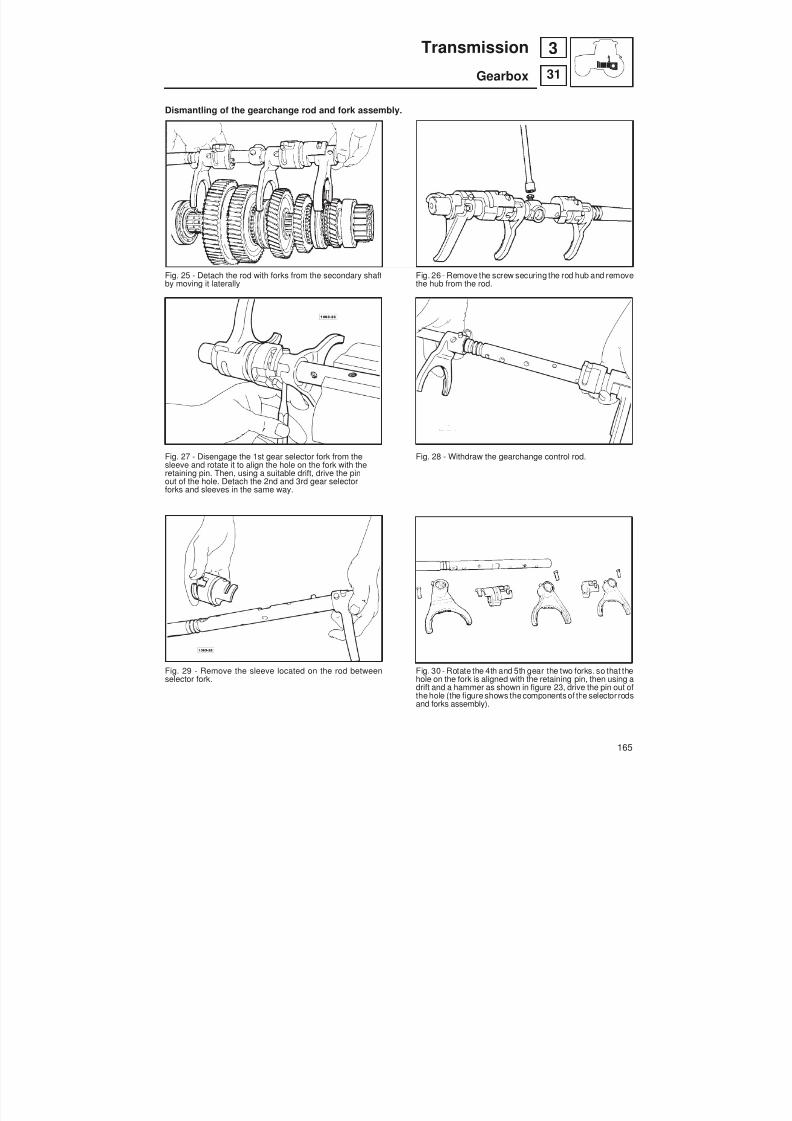
8/19/2019 Agrocompact f60 f70 f80 f90 Repair manual
http://slidepdf.com/reader/full/agrocompact-f60-f70-f80-f90-repair-manual 165/519
Dismantling of the gearchange rod and fork assembly.
Fig. 25 - Detach the rod with forks from the secondary shaftby moving it laterally
Fig. 27 - Disengage the 1st gear selector fork from thesleeve and rotate it to align the hole on the fork with theretaining pin. Then, using a suitable drift, drive the pinout of the hole. Detach the 2nd and 3rd gear selectorforks and sleeves in the same way.
Fig. 29 - Remove the sleeve located on the rod betweenselector fork.
Fig. 26 - Remove the screw securing the rod hub and removethe hub from the rod.
Fig. 28 - Withdraw the gearchange control rod.
Fig. 30 - Rotate the 4th and 5th gear the two forks. so that thehole on the fork is aligned with the retaining pin, then using adrift and a hammer as shown in figure 23, drive the pin out ofthe hole (the figure shows thecomponents of the selector rodsand forks assembly).
165
31
3Transmission
Gearbox

8/19/2019 Agrocompact f60 f70 f80 f90 Repair manual
http://slidepdf.com/reader/full/agrocompact-f60-f70-f80-f90-repair-manual 166/519
Dismantling of the gearchange selector rods and forks assembly
Fig. 31 - Unscrew the 6 retaining screws and remove thecover giving access to the gearchange selector rods andforks assembly. Then using a spanner, unscrew the guidebolt of the super-reduction control fork.
Fig. 33 - Unscrew the guide screw of the L-V selector fork.
Fig. 35 - Remove all the parts mounted on the rod, recoveringthem from the lateral access hole.
Fig. 32 - Unscrew the guide screw of the central sleevelocated between the 2 forks. (NB. Loctite has been applied tothese screws; we recommend that they are heated using anoxyacetylene torch to facilitate removal).
Fig. 34 - Access the front compartment of the gearbox extractthe rod by pulling the hub.
Fig. 36 - Parts comprising the selector rod and forks themfrom the lateral accesshole assembly for thesuper-reductionunit and range gears.
166
31
3 Transmission
Gearbox

8/19/2019 Agrocompact f60 f70 f80 f90 Repair manual
http://slidepdf.com/reader/full/agrocompact-f60-f70-f80-f90-repair-manual 167/519
Removal of the shaft with the actuator for engagement/disengagement of the front-wheel driveSeparate the rear gearbox from the frontgearbox, (it is first necessary to remove circlip ( A fig 37).Unscrew union B ( fig19 page 163) located on the left-hand side of the rear gearbox and remove the front shaft complete with the front-wheeldrive actuator.
IMPORTANT: Only unscrew union B fig. (19 page 163) located on the left-hand side of the rear gearbox when the twogearboxes are separated, as refitting is only possible in this condition.
Disassemble the unit, removing the circlip securing the oilmanifold and the circlip securing the thrust plate of the helicalspring; then disassemble the unit into its component parts, inspecting for wear the two oil seals (on the shaft and incontact with the control piston) and the areas in contact with the oil manifold.
WARNING: the valve located inside the shaft must be positioned as shown on page 173.
Fig. 37 - Front-wheel drive output.
Removal of the range gear shaftSeparate the rear gearbox from the front gearbox, (it is first necessary to remove circlip A fig. 37) remove the right rearwheel support and the cover on which the electro-hydraulic control valves are mounted, detach the oil pipe for 4WDdisengagement by undoing union B (fig. 19 on page 163) located on thesolenoid valve mounting on the right-hand sideof the gearbox. Remove the cover supporting the internal parking brake control.Then remove the synchronised P.T.O. shaft by removing the retaining flange mounted on the rear of the gearbox andremove the synchronised P.T.O. engagement sleeve mounted on the 4WD shaft, which can be accessed through thespace left void by removal of the wheel support.Remove circlip B fig. 37 and thrust plate C fig. 37, which can be accessed through the space created by removal of the
wheel support.Working through the aperture created by removal of the cover on which the electro-hydraulic control valves aremounted, remove circlips D - E - F - G fig. 37 and pull shaft towards the front of the gearbox.
167
31
3Transmission
Gearbox
A BC D E F G

8/19/2019 Agrocompact f60 f70 f80 f90 Repair manual
http://slidepdf.com/reader/full/agrocompact-f60-f70-f80-f90-repair-manual 168/519

8/19/2019 Agrocompact f60 f70 f80 f90 Repair manual
http://slidepdf.com/reader/full/agrocompact-f60-f70-f80-f90-repair-manual 169/519
ADJUSTING PLAY OF THE GEARBOX SHAFTS BY MEANS OF THE THRUST PLATES ON THEMINI/INVERSOR SHAFT AND THE SECONDARY SHAFT
MINI/INVERSOR SHAFTS
Circlip position for measurement of distance “x”
Adjusting the play of the minireduction gear mounted on the inversor shaft.Obtain an play X of 0.15 0.30 mm of minireduction gear (z=35) by selecting the thrust plate R of the appropriate thic -kness from among those available:
cod. 008.0251.0 010.0629.0 010.0630.0 010.0631.0 010.0632.0
Play X is to be measured by pushing the spacer B in the direction indicated by the arrow up to the point where thesynchroniser is pushed up against point Y, while simultaneously pushing the forward speed gear (z=37) in the directionindicated by the arrow up against circlip A .
+
Circlip position for measurement of distance “x”
Adjusting the play of the forward speed gear on the inversor shaft (version with minireduction).Obtain an play X of 0.15 0.30 mm of the forward speed gear (z=35) by selecting the thrust plate R of the appropriatethickness from among those available:
cod. 008.0251.0 010.0629.0 010.0630.0 010.0631.0 010.0632.0
Play X is to be measured by pushing the gear (z=23) in the direction indicated by the arrow so that the synchroniser ispushed up against point Y, while simultaneously pushing the minireduction gear (z=35) in the direction indicated by thearrow up against circlip A.
169
31
3Transmission
Gearbox

8/19/2019 Agrocompact f60 f70 f80 f90 Repair manual
http://slidepdf.com/reader/full/agrocompact-f60-f70-f80-f90-repair-manual 170/519
REVERSE SHAFT
Circlip position for measurement of distance “x”
Adjusting the play of the reverse gearwheel mounted on the shuttle shaft.Obtain play X of 0.15 to 0.30 mm of reverse gearwheel (z = 23) by selecting and fitting a thrust washer R of suitablethickness from those available:
code 008.0251.0 010.0629.0 010.0630.0 010.0631.0 010.0632.0
Play X is measured by pushing the forward gearwheel (z=37) in the direction indicated by the arrow, thereby pushingthe synchronizer up against point Y and pushing the circlip A as indicated in the detail.
SECONDARY SHAFT 1st SPEED
Circlip position for measurement of distance “x”
Adjusting the play of the 1st speed gear (z=59) .Obtain an play X of 0.15 0.30 mm of the 1st speed gear (z=59) by selecting the thrust plate R of the appropriate thic -kness from among those available:
cod. 008.0251.0 010.0629.0 010.0630.0 010.0631.0 010.0632.0
Play X is to be measured with a feeler gauge while pushing spacer B in the direction indicated by the arrow so that thesynchroniser is pushed up against point Y , while simultaneously pushing the 2nd speed gear (z=50) in the directionindicated by the arrow up against circlip A .
170
3 Transmission
Gearbox
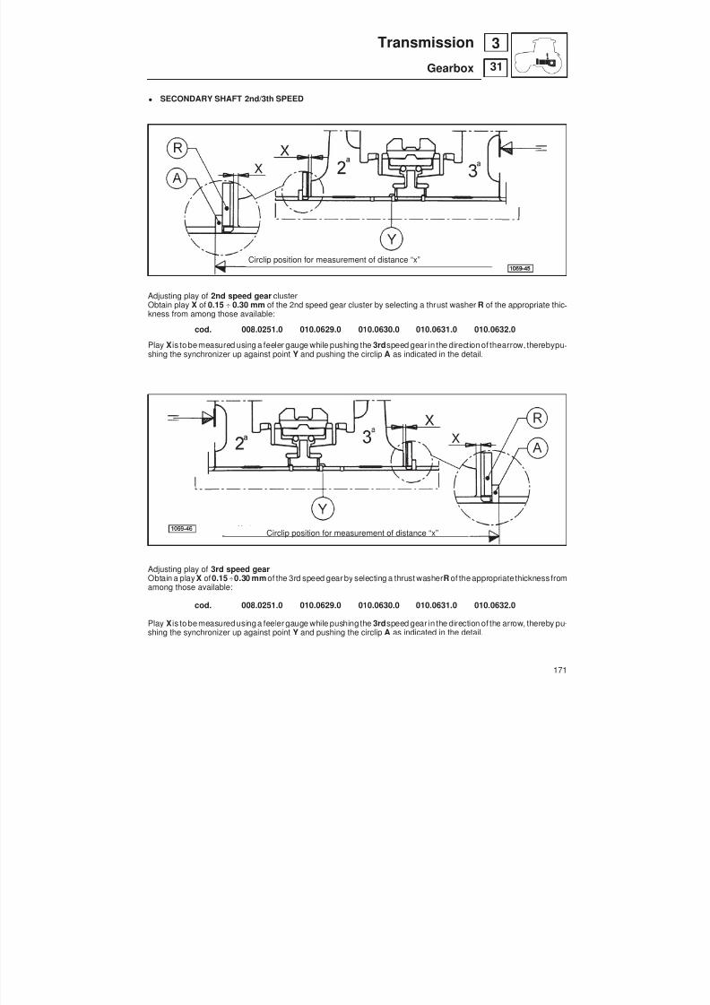
8/19/2019 Agrocompact f60 f70 f80 f90 Repair manual
http://slidepdf.com/reader/full/agrocompact-f60-f70-f80-f90-repair-manual 171/519
SECONDARY SHAFT 2nd/3th SPEED
Circlip position for measurement of distance “x”
Adjusting play of 2nd speed gear clusterObtain play X of 0.15 0.30 mm of the 2nd speed gear cluster by selecting a thrust washer R of the appropriate thic -kness from among those available:
cod. 008.0251.0 010.0629.0 010.0630.0 010.0631.0 010.0632.0
Play Xis to be measured using a feeler gauge while pushing the 3rd speed gear in the direction of thearrow, therebypu -shing the synchronizer up against point Y and pushing the circlip A as indicated in the detail.
Circlip position for measurement of distance “x”
Adjusting play of 3rd speed gearObtain a play X of 0.15 0.30 mm of the 3rd speed gear by selecting a thrust washer R of the appropriate thickness fromamong those available:
cod. 008.0251.0 010.0629.0 010.0630.0 010.0631.0 010.0632.0Play Xis to be measured using a feeler gauge while pushing the 3rd speed gear in the direction of the arrow, thereby pu -shing the synchronizer up against point Y and pushing the circlip A as indicated in the detail.
171
31
3Transmission
Gearbox

8/19/2019 Agrocompact f60 f70 f80 f90 Repair manual
http://slidepdf.com/reader/full/agrocompact-f60-f70-f80-f90-repair-manual 172/519
SECONDARY SHAFT 4th/5th SPEED
circlip position for measurement of distance "X"
Adjusting the play of the 4th speed gear cluster.Obtain a play X of 0.15 to 0.30 mm of the 4th speed gear cluster by selecting and fitting a thrust washer R of the appro -priate thickness from those available:
code 008.0251.0 010.0629.0 010.0630.0 010.0631.0 010.0632.0
Play X is to be measured using a feeler gauge while pushing the 3rd speed gear in the direction of the arrow, therebypushing the synchronizer up against point Y and pushing the circlip A as indicated in the detail.
SECONDARY SHAFT
Shimming the front bearing of thesecondary shaftFit shims of appropriate thickness to reduceend-float between the shaft and the bearingto the minimum possible amount. By fittingthe correct shims you can obtain amaximum play of 0.09 mm.
INPUT SHAFT AND INVERSOR SHAFT
Fitting the bush joining the input shaft to the inversor shaftFit bush A oriented as shown in the figure to facilitate subsequentremoval.
172
31
3 Transmission
Gearbox

8/19/2019 Agrocompact f60 f70 f80 f90 Repair manual
http://slidepdf.com/reader/full/agrocompact-f60-f70-f80-f90-repair-manual 173/519
Fitting the spacer determining the stroke of the valve for hydraulic disengagement of front-wheel drive.To allow correct disengagement of the front-wheel drive, bush A must be installed as shown in the figure above.
WARNINGS RELATED TO ASSEMBLY OF THE GEARS OF THE P.T.O. UNIT, THE RANGEREDUCTION UNIT AND THE SYNCHRONISED P.T.O. SHAFTAssembly of the P.T.O.Install:— The synchronised P.T.O. output shaft (to be installed after the range reduction unit);— The P.T.O. output shaft and relative gears;— The rear P.T.O. shaft.
Installation of the range reduction unit, the gear for the front-wheel drive shaft and theparking brake discs— Position on the bottom of the gearbox the L-V range reduction unit (complete with bushes and roller cage) and the
super-reduction gear (complete with roller cage).— Slide the shaft, complete with circlip, through the front end of the gearbox, and fit the previously positioned gearsonto the shaft.— Fit the thrust washer and 2 circlips.— Position the drive gear of the front-wheel drive complete with parking brake discs.— Fit the ball bearing for the rear end of the shaft, inserting it in its housing in the gearbox.— Insert the thrust washer and position the circlip.— Position the bearing and the bearing circlip in the housing;— Fit the thrust washer and the circlip;— Install the synchronised P.T.O. shaft in the rear end of the gearbox, and fit the control sleeve to the shaft.— Fit the bevel pinion and the gears of the range reduction unit with the relative synchroniser;— Fit the differential housing complete with the crown wheel and the internal diff. lock control.Warnings:The spacer installed on the rear output shaft is fitted with an O-ring on the outer surface and an internal oil seal.To remove this spacer requires the use of a puller to be attached to the spacer using the two holes provided.At each dismantling of the pins of the brake and clutch control levers, check the bushes for wear.
173
31
3Transmission
Gearbox

8/19/2019 Agrocompact f60 f70 f80 f90 Repair manual
http://slidepdf.com/reader/full/agrocompact-f60-f70-f80-f90-repair-manual 174/519
Fig. 42 - Range gearbox
Fig. 43 - Removal of the groundspeed P.T.O. sleeve. Fig. 44 - Removal of the circlip securing the shaft.
FIg. 45 - Gears on range gearbox shaft. Fig. 46 - Checking the oil seals on the 4WD shaft.
174
31
3 Transmission
Gearbox
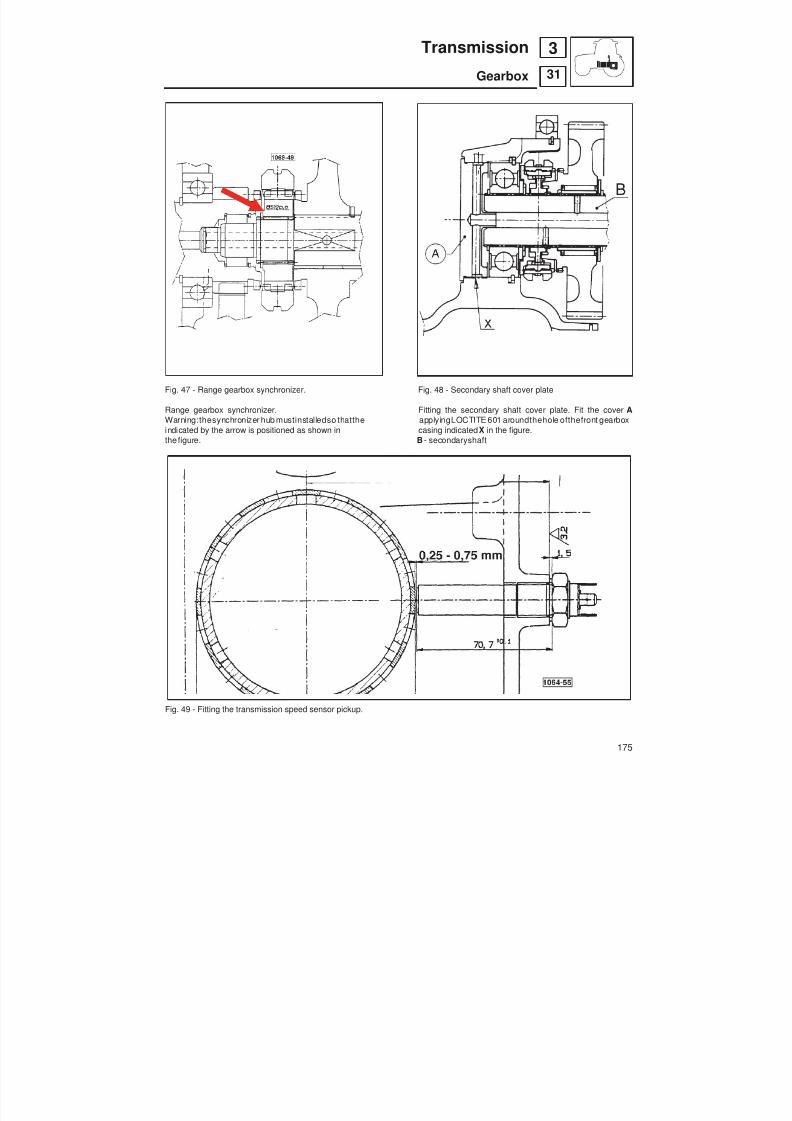
8/19/2019 Agrocompact f60 f70 f80 f90 Repair manual
http://slidepdf.com/reader/full/agrocompact-f60-f70-f80-f90-repair-manual 175/519
Fig. 47 - Range gearbox synchronizer. Fig. 48 - Secondary shaft cover plate
Range gearbox synchronizer. Fitting the secondary shaft cover plate. Fit the cover AWarning:thesynchronizer hub mustinstalledso thatthe applyingLOCTITE 601 aroundthehole ofthefront gearboxindicated by the arrow is positioned as shown in casing indicated X in the figure.the figure. B - secondaryshaft
Fig. 49 - Fitting the transmission speed sensor pickup.
175
31
3Transmission
Gearbox

8/19/2019 Agrocompact f60 f70 f80 f90 Repair manual
http://slidepdf.com/reader/full/agrocompact-f60-f70-f80-f90-repair-manual 176/519
Fitting the baulk ring of the synchronizer forthe1 st speed gear mounted on the secon -dary shaft.Should it be necessary to restore the correctplay X of 0.15 to 0.30 mm of the 1 st speedgear (z=59), it is possible to select asynchroniser baulk ring of suitable thic -kness from the two available, as shown inthe figure.
Fig. 51 - Bearing for4WD shaft.
Fig. 50 - Fit the 50x90x20 ball bearing, indicated A in the figure,without the retaining ring.
Fig. 52 - Position the groundspeed P.T.O. cover plate as indicatedin the figure.
176
31
3 Transmission
Gearbox

8/19/2019 Agrocompact f60 f70 f80 f90 Repair manual
http://slidepdf.com/reader/full/agrocompact-f60-f70-f80-f90-repair-manual 177/519
Points where sealant is to be used
Fig. 53 - Rear gearbox.Apply LOCTITE n°601 to the base of studs A (n°9) - B (n°1) - C (n°1), as shown in the figure, prior to assembly.
Fig. 54 - Fitting the wheel support.Apply PIANERMETIC 510 sealant to the surfaces indicated with the letter L in the figure; apply SILASTIK sealant to the surfacesindicated with the letter S .
177
31
3Transmission
Gearbox

8/19/2019 Agrocompact f60 f70 f80 f90 Repair manual
http://slidepdf.com/reader/full/agrocompact-f60-f70-f80-f90-repair-manual 178/519
Fig. 55 - Tightening the bolts of the gear selector linkage.After fully tightening the bolts A indicated in the figure, check that distance K is equal to 3 mm .
178
31
3 Transmission
Gearbox
CAMBIO
LEVA INVERSORELEVA CAMBIO
K
A
A
K A
A
Lato Destro Lato Sinistro
K
K
Right Side Left Side
GEAR LEVER SHUTTLE LEVER

8/19/2019 Agrocompact f60 f70 f80 f90 Repair manual
http://slidepdf.com/reader/full/agrocompact-f60-f70-f80-f90-repair-manual 179/519
Fig. 56 - Tightening the bolts of the gear selector linkage.After fully tightening the bolts A indicated in the figure, check that distance K is equal to 3 mm .
Fig. 57 - Silastik and grease application. Apply a coatingof Silastik between the face of the front gearbox and the retaining face of therubber gasket. Apply grease to the sections of the selector rods indicated * in the figure.
179
31
3Transmission
Gearbox
A
CAMBIO A
K
K
Spalmare Silastic
80 *
80 *
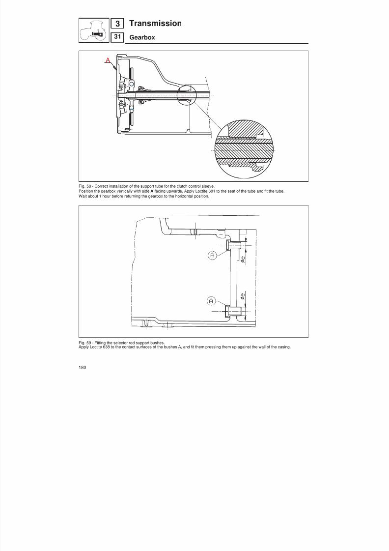
8/19/2019 Agrocompact f60 f70 f80 f90 Repair manual
http://slidepdf.com/reader/full/agrocompact-f60-f70-f80-f90-repair-manual 180/519
Fig. 58 - Correct installation of the support tube for the clutch control sleeve.Position the gearbox vertically with side A facing upwards. Apply Loctite 601 to the seat of the tube and fit the tube.Wait about 1 hour before returning the gearbox to the horizontal position.
Fig. 59 - Fitting the selector rod support bushes.Apply Loctite 638 to the contact surfaces of the bushes A, and fit them pressing them up against the wall of the casing.
180
31
3 Transmission
Gearbox
12"
11"
A
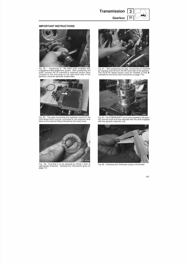
8/19/2019 Agrocompact f60 f70 f80 f90 Repair manual
http://slidepdf.com/reader/full/agrocompact-f60-f70-f80-f90-repair-manual 181/519
IMPORTANT INSTRUCTIONS
Fig. 60 - Positioning of the 4WD shaft complete withengagement/disengagement system. After positioning theshaft, connect the oil manifold to solenoid control valve(located on the mounting on the right-hand side of thegearbox) using the specially shaped pipe.
Fig. 62 - The pipe connecting the hydraulic control of thefront-wheel drive must be connected to the solenoid valveblock at the external fitting indicated by the small arrow.
Fig. 64 - End-float is to be adjusted by fitting a shim ofappropriate thickness following the instructions given onpage 137.
Fig. 61 - After positioning the pipe, connect the oil manifoldby inserting union A from the left-hand side of the gearbox.The PICK-UP speed sensor must be installed in hole Bindicated by the arrow (see instructions on page 175).
Fig. 63 - The POWERSHIFT unit is to be installed in the gear -box and the shaft end-float adjusted with the shaft engagedwith the epicyclic reduction unit.
Fig. 65 - Checking shim thickness using a micrometer.
181
31
3Transmission
Gearbox
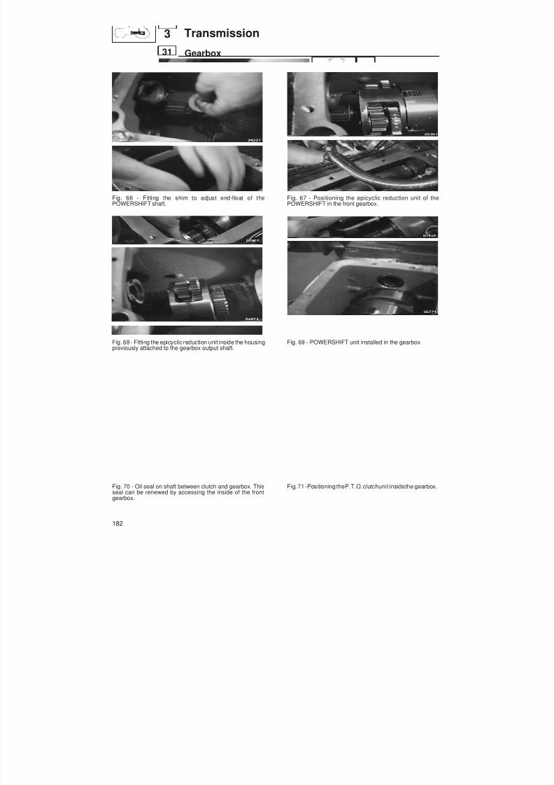
8/19/2019 Agrocompact f60 f70 f80 f90 Repair manual
http://slidepdf.com/reader/full/agrocompact-f60-f70-f80-f90-repair-manual 182/519
Fig. 66 - Fitting the shim to adjust end-float of thePOWERSHIFT shaft.
Fig. 68 - Fitting the epicyclic reduction unit inside the housingpreviously attached to the gearbox output shaft.
Fig. 70 - Oil seal on shaft between clutch and gearbox. Thisseal can be renewed by accessing the inside of the frontgearbox.
Fig. 67 - Positioning the epicyclic reduction unit of thePOWERSHIFT in the front gearbox.
Fig. 69 - POWERSHIFT unit installed in the gearbox.
Fig. 71 -Positioning theP.T.O. clutchunit insidethe gearbox.
182
31
3 Transmission
Gearbox
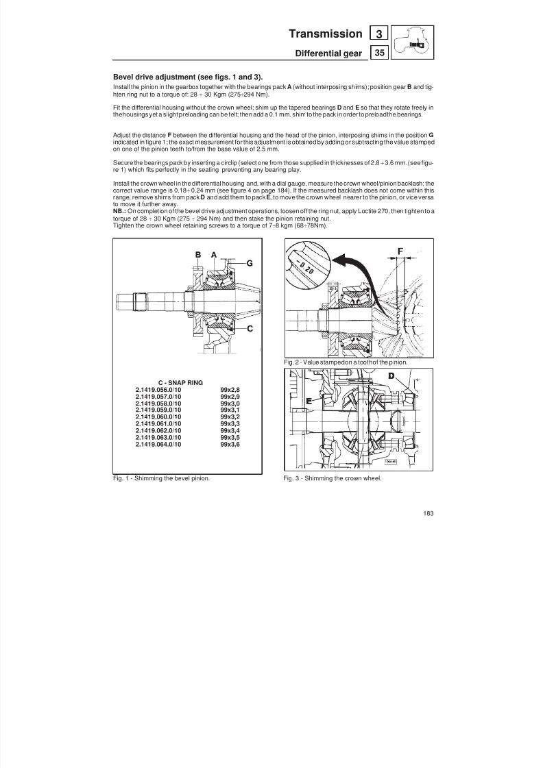
8/19/2019 Agrocompact f60 f70 f80 f90 Repair manual
http://slidepdf.com/reader/full/agrocompact-f60-f70-f80-f90-repair-manual 183/519
Bevel drive adjustment (see figs. 1 and 3).Install the pinion in the gearbox together with the bearings pack A (without interposing shims); position gear B and tig -hten ring nut to a torque of: 28 30 Kgm (275 294 Nm).
Fit the differential housing without the crown wheel; shim up the tapered bearings D and E so that they rotate freely inthehousingsyet a slightpreloading can be felt; then add a 0.1 mm. shimto the pack in order to preloadthe bearings.
Adjust the distance F between the differential housing and the head of the pinion, interposing shims in the position Gindicated in figure 1; the exact measurement for this adjustment is obtained by adding or subtracting thevalue stampedon one of the pinion teeth to/from the base value of 2.5 mm.
Secure the bearings pack by inserting a circlip (select one from those supplied in thicknesses of 2.8 3.6 mm.(see figu -re 1) which fits perfectly in the seating preventing any bearing play.
Install the crown wheel in the differential housing and, with a dial gauge, measure the crown wheel/pinionbacklash; thecorrect value range is 0.18 0.24 mm (see figure 4 on page 184). If the measured backlash does not come within thisrange, remove shims from pack D and add them to pack E, to move the crown wheel nearer to the pinion, or vice versato move it further away.NB.: On completion of the bevel drive adjustment operations, loosen off the ring nut, apply Loctite 270, then tighten to atorque of 28 30 Kgm (275 294 Nm) and then stake the pinion retaining nut.Tighten the crown wheel retaining screws to a torque of 7 8 kgm (68 78Nm).
Fig. 2 - Value stampedon a toothof the pinion.
C - SNAP RING2.1419.056.0/10 99x2,82.1419.057.0/10 99x2,92.1419.058.0/10 99x3,02.1419.059.0/10 99x3,12.1419.060.0/10 99x3,22.1419.061.0/10 99x3,32.1419.062.0/10 99x3,42.1419.063.0/10 99x3,52.1419.064.0/10 99x3,6
Fig. 1 - Shimming the bevel pinion. Fig. 3 - Shimming the crown wheel.
183
35
3Transmission
Differential gear
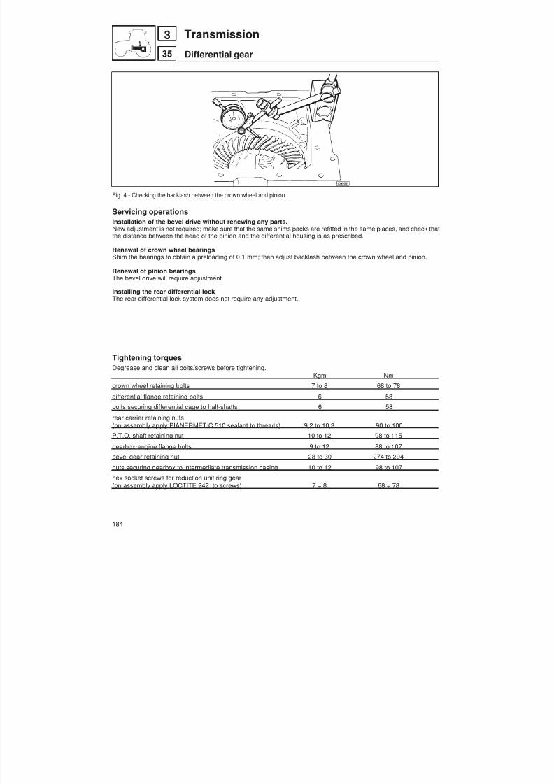
8/19/2019 Agrocompact f60 f70 f80 f90 Repair manual
http://slidepdf.com/reader/full/agrocompact-f60-f70-f80-f90-repair-manual 184/519
Fig. 4 - Checking the backlash between the crown wheel and pinion.
Servicing operationsInstallation of the bevel drive without renewing any parts.New adjustment is not required; make sure that the same shims packs are refitted in the same places, and check thatthe distance between the head of the pinion and the differential housing is as prescribed.
Renewal of crown wheel bearingsShim the bearings to obtain a preloading of 0.1 mm; then adjust backlash between the crown wheel and pinion.
Renewal of pinion bearingsThe bevel drive will require adjustment.
Installing the rear differential lockThe rear differential lock system does not require any adjustment.
Tightening torquesDegrease and clean all bolts/screws before tightening.
Kgm Nm
crown wheel retaining bolts 7 to 8 68 to 78
differential flange retaining bolts 6 58
bolts securing differential cage to half-shafts 6 58
rear carrier retaining nuts(on assembly apply PIANERMETIC 510 sealant to threads) 9,2 to 10,3 90 to 100
P.T.O. shaft retaining nut 10 to 12 98 to 115
gearbox-engine flange bolts 9 to 12 88 to 107
bevel gear retaining nut 28 to 30 274 to 294
nuts securing gearbox to intermediate transmission casing 10 to 12 98 to 107
hex socket screws for reduction unit ring gear(on assembly apply LOCTITE 242 to screws) 7 ÷ 8 68 ÷ 78
184
35
3 Transmission
Differential gear
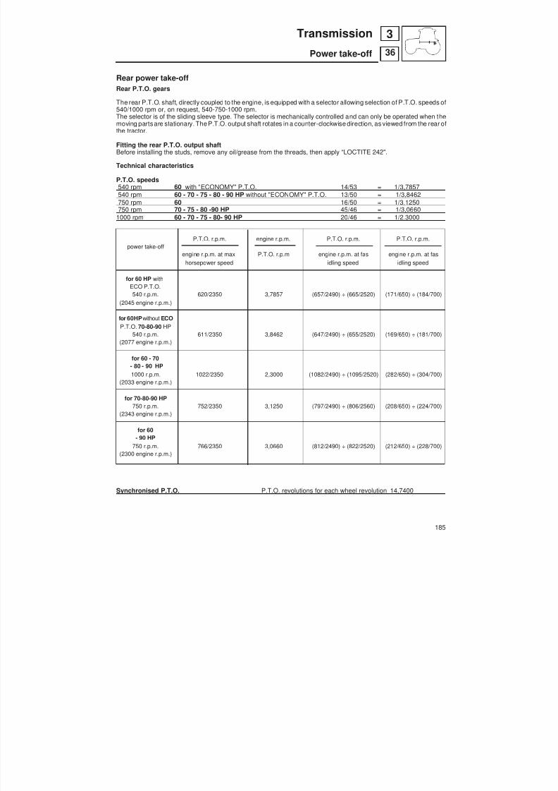
8/19/2019 Agrocompact f60 f70 f80 f90 Repair manual
http://slidepdf.com/reader/full/agrocompact-f60-f70-f80-f90-repair-manual 185/519
Rear power take-offRear P.T.O. gears
The rear P.T.O. shaft, directly coupled to the engine, is equipped with a selector allowing selection of P.T.O. speeds of540/1000 rpm or, on request, 540-750-1000 rpm.The selector is of the sliding sleeve type. The selector is mechanically controlled and can only be operated when themoving parts are stationary. TheP.T.O. output shaft rotates in a counter-clockwise direction, as viewed from the rear ofthe tractor.
Fitting the rear P.T.O. output shaftBefore installing the studs, remove any oil/grease from the threads, then apply “LOCTITE 242".
Technical characteristics
P.T.O. speeds540 rpm 60 with "ECONOMY" P.T.O. 14/53 = 1/3,7857540 rpm 60 - 70 - 75 - 80 - 90 HP without "ECONOMY" P.T.O. 13/50 = 1/3,8462750 rpm 60 16/50 = 1/3,1250750 rpm 70 - 75 - 80 -90 HP 45/46 = 1/3,0660
1000 rpm 60 - 70 - 75 - 80- 90 HP 20/46 = 1/2,3000
P.T.O. r.p.m. engine r.p.m. P.T.O. r.p.m. P.T.O. r.p.m.power take-off
engine r.p.m. at max P.T.O. r.p.m engine r.p.m. at fas engine r.p.m. at fashorsepower speed idling speed idling speed
for 60 HP with
ECO P.T.O.540 r.p.m. 620/2350 3,7857 (657/2490) ÷ (665/2520) (171/650) ÷ (184/700)
(2045 engine r.p.m.)
for 60HP without ECOP.T.O. 70-80-90 HP
540 r.p.m. 611/2350 3,8462 (647/2490) ÷ (655/2520) (169/650) ÷ (181/700)(2077 engine r.p.m.)
for 60 - 70- 80 - 90 HP1000 r.p.m. 1022/2350 2,3000 (1082/2490) ÷ (1095/2520) (282/650) ÷ (304/700)
(2033 engine r.p.m.)
for 70-80-90 HP750 r.p.m. 752/2350 3,1250 (797/2490) ÷ (806/2560) (208/650) ÷ (224/700)
(2343 engine r.p.m.)
for 60- 90 HP
750 r.p.m. 766/2350 3,0660 (812/2490) ÷ (822/2520) (212/650) ÷ (228/700)(2300 engine r.p.m.)
Synchronised P.T.O. P.T.O. revolutions for each wheel revolution 14,7400
185
36
3Transmission
Power take-off

8/19/2019 Agrocompact f60 f70 f80 f90 Repair manual
http://slidepdf.com/reader/full/agrocompact-f60-f70-f80-f90-repair-manual 186/519
Fig. 1 - Rear P.T.O. speed configurations.
186
36
3 Transmission
Power take-off

8/19/2019 Agrocompact f60 f70 f80 f90 Repair manual
http://slidepdf.com/reader/full/agrocompact-f60-f70-f80-f90-repair-manual 187/519
2-speed version 540 – 750 rpm
WARNING: on assembly, position the lever indicated with thearrow so that head of the lock screw is facing the frontof the tractor.
2-speed version 540 – 1000 rpm
Fig. 2 - P.T.O. controls and output shafts (2-speed version) for 60 HP models
187
36
3Transmission
Power take-off
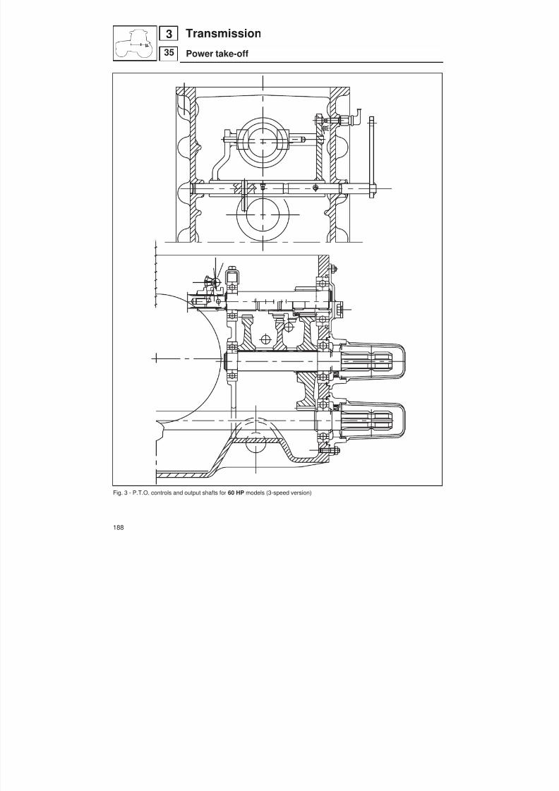
8/19/2019 Agrocompact f60 f70 f80 f90 Repair manual
http://slidepdf.com/reader/full/agrocompact-f60-f70-f80-f90-repair-manual 188/519
Fig. 3 - P.T.O. controls and output shafts for 60 HP models (3-speed version)
188
35
3 Transmission
Power take-off

8/19/2019 Agrocompact f60 f70 f80 f90 Repair manual
http://slidepdf.com/reader/full/agrocompact-f60-f70-f80-f90-repair-manual 189/519
Fig. 4 - P.T.O. controls and output shafts for 70 - 80 - 90 HP models (3-speed version).
189
36
3Transmission
Power take-off
9 kgm(90 Nm)

8/19/2019 Agrocompact f60 f70 f80 f90 Repair manual
http://slidepdf.com/reader/full/agrocompact-f60-f70-f80-f90-repair-manual 190/519
Fig. 5 - P.T.O. controls and output shafts for 70 - 80 - 90 HP models (2-speed 540/1000 + groundspeed version).
190
36
3 Transmission
Power take-off
z 22
30 Km/h
C.51.2
30x72x19
z 38
30x72x19
C.51.2
z13Sx
z50Dx
540-1000 + SINCRO
z20
z46
9 kgm(90 Nm)
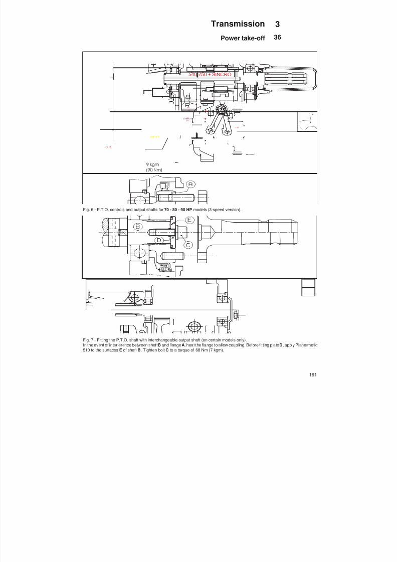
8/19/2019 Agrocompact f60 f70 f80 f90 Repair manual
http://slidepdf.com/reader/full/agrocompact-f60-f70-f80-f90-repair-manual 191/519
Fig. 6 - P.T.O. controls and output shafts for 70 - 80 - 90 HP models (3-speed version).
Fig. 7 - Fitting the P.T.O. shaft with interchangeable output shaft (on certain models only).In the event of interference between shaft B and flange A, heat the flange to allow coupling. Before fitting plate D , apply Pianermetic510 to the surfaces E of shaft B . Tighten bolt C to a torque of 68 Nm (7 kgm).
191
36
3Transmission
Power take-off
C.R.
30 Km/h
z 38
z13
Sx
z50
Dx
540-750 + SINCRO
z16
z50
9 kgm(90 Nm)
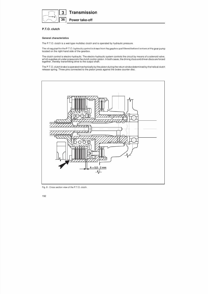
8/19/2019 Agrocompact f60 f70 f80 f90 Repair manual
http://slidepdf.com/reader/full/agrocompact-f60-f70-f80-f90-repair-manual 192/519
P.T.O. clutch
General characteristics
The P.T.O. clutch is a wet-type multidisc clutch and is operated by hydraulic pressure.
The oil required for theP.T.O. hydraulic control is drawn from the gearboxand filtered before it arrives at the gear pumplocated on the right-hand side of the gearbox.
The clutch control is electro-hydraulic. The electro-hydraulic system controls the circuit by means of a solenoid valve,which supplies oil under pressureto the clutch control piston. In both cases, the driving discs and driven discs are forcedtogether, thereby transmitting drive to the output shaft.
The P.T.O. clutch brake is operatedmechanically by the piston during the return stroke determined by thehelical clutchrelease spring. Three pins connected to the piston press against the brake counter disc.
Fig. 8 - Cross section view of the P.T.O. clutch.
192
36
3 Transmission
Power take-off
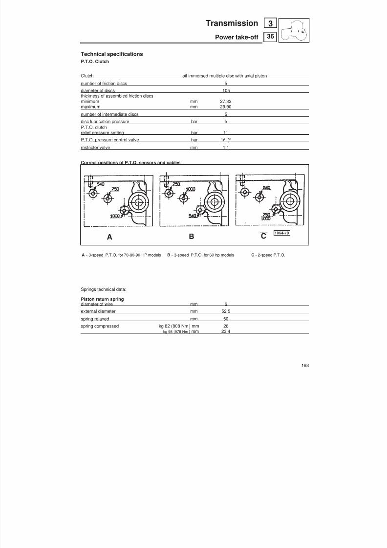
8/19/2019 Agrocompact f60 f70 f80 f90 Repair manual
http://slidepdf.com/reader/full/agrocompact-f60-f70-f80-f90-repair-manual 193/519
Technical specificationsP.T.O. Clutch
Clutch oil-immersed multiple disc with axial piston
number of friction discs 5
diameter of discs 105thickness of assembled friction discsminimum mm 27.32maximum mm 29.90
number of intermediate discs 5
disc lubrication pressure bar 5P.T.O. clutch
relief pressure setting bar 11P.T.O. pressure control valve bar 16 0
2+
restrictor valve mm 1.1
Correct positions of P.T.O. sensors and cables
A - 3-speed P.T.O. for 70-80-90 HP models B - 3-speed P.T.O. for 60 hp models C - 2-speed P.T.O.
Springs technical data:
Piston return springdiameter of wire mm 6
external diameter mm 52,5
spring relaxed mm 50
spring compressed kg 82 (808 Nm ) mm 28
kg 98 (978 Nm ) mm 23,4
193
36
3Transmission
Power take-off
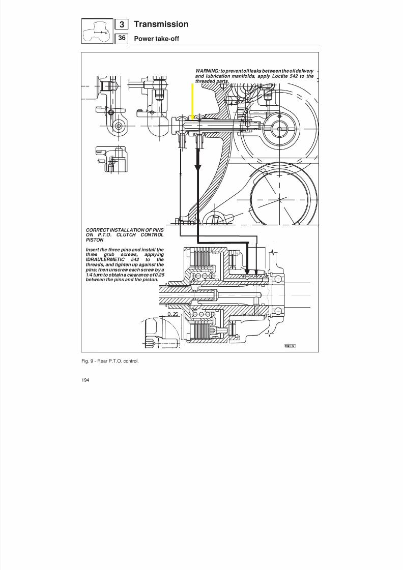
8/19/2019 Agrocompact f60 f70 f80 f90 Repair manual
http://slidepdf.com/reader/full/agrocompact-f60-f70-f80-f90-repair-manual 194/519
CORRECT INSTALLATION OF PINS ON P.T.O. CLUTCH CONTROLPISTON
Insert the three pins and install the three grub screws, applying IDRAULERMETIC 542 to the threads, and tighten up against the pins; then unscrew each screw by a
1/4 turn to obtain a clearance of 0.25 between the pins and the piston.
Fig. 9 - Rear P.T.O. control.
WARNING: to preventoil leaks between the oildelivery and lubrication manifolds, apply Loctite 542 to the threaded parts.
194
36
3 Transmission
Power take-off

8/19/2019 Agrocompact f60 f70 f80 f90 Repair manual
http://slidepdf.com/reader/full/agrocompact-f60-f70-f80-f90-repair-manual 195/519

8/19/2019 Agrocompact f60 f70 f80 f90 Repair manual
http://slidepdf.com/reader/full/agrocompact-f60-f70-f80-f90-repair-manual 196/519
Checking clutch hydraulic pressuresConnect themini fitting code 009.2923.4 (with M4 12x1.5 threaded fitting) to the electro-hydraulic control unitas shownin figure 11.Connect tool 5.9030.517.4 to the fitting and attach the pressure gauge 5.9030.514.0.Operate the control valve and check that the pressure gauge shows a reading of approximately 16 bar.For instructions on measuring pressure and relative values see the chapter “electro-hydraulic controls”.
Fig. 11 - Checking the operating pressure in the P.T.O. clutch control circuit.
196
36
3 Transmission
Power take-off

8/19/2019 Agrocompact f60 f70 f80 f90 Repair manual
http://slidepdf.com/reader/full/agrocompact-f60-f70-f80-f90-repair-manual 197/519
Checking the end-play of the front shaft of the P.T.O. clutchOn the front shaft of the P.T.O., install circlip A and thrust washer B code 2.1599.761.0; position the shaft in the clutchunit and push it towards the front of the tractor so that it rest up against the oil seal shown in figure at C , then check thatclearance between the thrust washer B and the clutch hub is not less than 1 mm.If the clearance is less than 1 mm, remove thrust washer B .
Fig. 12 - Checking the end-play of the front shaft of the P.T.O. clutch.
Fig. 13 - Installation of the waterproof seals.
Installing the waterproof sealsRearP.T.O.output shaft andsynchronised P.T.O.Fit the seal using a suitable installation tool;the seal is to be oriented as shown in the figureand pressed in to the full depth of the tool.The measurements indicated here are to beused to construct the oil seal installation tool.
197
36
3Transmission
Power take-off

8/19/2019 Agrocompact f60 f70 f80 f90 Repair manual
http://slidepdf.com/reader/full/agrocompact-f60-f70-f80-f90-repair-manual 198/519
RENEWAL OF THE REAR P.T.O. CLUTCH
The P.T.O. clutch unit can be removed without having to remove the driving platform.
proceed as follows:
— Remove the top link;— Detach the lift rods of the 3-point linkage from the lift arms;— Detach the lift control rods from the control levers;— Disconnect the oil delivery pipe to the auxiliary control valves from the rear pump;— On models with 4-way control valves, detach the oil pipe from the lift control valve to the auxiliary hydraulic control
valves. On models with 6-way controlvalves, detachalso thepipe from hydraulic controlvalves to theupper gearboxcover plate (for 4-way control valves);
— Disconnect the controllevers of thehydraulic control valves from the relay levers connected to thecontrol valves, byremoving the relative cotter pins and retaining pins;
— Remove the 3 screws securing the hydraulic control valve from the support bracket;— Remove the 9 screws and the two nuts securing the lift unit to the rear gearbox;— Attach the lift unit to a hoist and lift it clear of the tractor (when removing the lift unit, take care not to damage the thre -
ads on the two studs);— Unscrew the screws securing the P.T.O. access cover (located above the gearbox) and remove this cover;— Using a suitable lever, push towards the front of the tractor the sleeve coupling the P.T.O. clutch output shaft to the
P.T.O. rear shaft;— Loosen the two screws and remove the rear shaft bearing stop plate;
NOTE: when removing this plate, take care that thespacers positioned underneath it do not fall into thegearbox.
— Unscrew the3 retaining screws and remove thetop flange located at the rear of the gearbox. Then withdraw the bea -ring together with the upper 540 rpm gear.NOTE: when withdrawing the gear, take care that the roller bearing located in thegeardoes not fall into the gearbox.
— Disconnect thepipe supplying oil for lubrication of theinversor shaftand to the oil-bath for the P.T.O. clutch discs, lo -cated on the right-hand side of the gearbox, by undoing the relative union; then remove the union of the oil supplypipe to the P.T.O. clutch;
— With the aid of a lever, push the P.T.O. shaft a few centimetres to the rear;This will only be possible if the shaft is positioned in such a way that there is no interference between the teethof thegear and those on the shaft;
— Slide the sleeve onto the rear shaftafter having firstpushed thebearing located in thewall of thegearbox back a suf -ficient distance;
— Push the clutch unit together with the front shaft and the output shaft to therear, so as to be able to withdraw the frontshaft to the front P.T.O. unit;
— Extract the complete clutch unit, disengaging it from the rear shaft;— Inspect the clutch discs and renew them if necessary, removing the large circlip and the spacer.
WARNING: on re-assembly, after having positioned theclutch unit complete with the front shaft, refit the two oil unionsin order to ensure that the unit is positioned correctly, then insert the rear shafts and complete the assembly.
198
36
3 Transmission
Power take-off
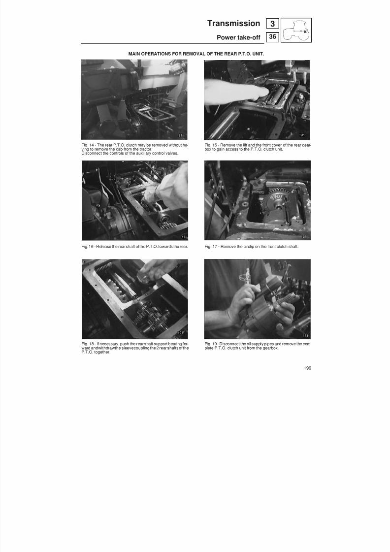
8/19/2019 Agrocompact f60 f70 f80 f90 Repair manual
http://slidepdf.com/reader/full/agrocompact-f60-f70-f80-f90-repair-manual 199/519
MAIN OPERATIONS FOR REMOVAL OF THE REAR P.T.O. UNIT.
Fig. 14 - The rear P.T.O. clutch may be removed without ha -ving to remove the cab from the tractor.Disconnect the controls of the auxiliary control valves.
Fig.16 - Release the rearshaft ofthe P.T.O.towards the rear.
Fig. 18 - If necessary, push the rear shaft support bearing for -ward andwithdrawthe sleevecoupling the2 rear shaftsof theP.T.O. together.
Fig. 15 - Remove the lift and the front cover of the rear gear -box to gain access to the P.T.O. clutch unit.
Fig. 17 - Remove the circlip on the front clutch shaft.
Fig. 19 - Disconnect the oil supply pipes and remove the com -plete P.T.O. clutch unit from the gearbox.
199
36
3Transmission
Power take-off

8/19/2019 Agrocompact f60 f70 f80 f90 Repair manual
http://slidepdf.com/reader/full/agrocompact-f60-f70-f80-f90-repair-manual 200/519
OPERATIONS FOR REMOVAL OF THE REAR P.T.O. UNIT
Fig. 20 - Withdraw the front shaft from the clutch unit.
Fig. 22 - Check the condition of the lube pipe and nozzle forthe hydraulic pumps drive gears.
Fig. 24 - Remove the clutch discs.
Fig.21 - Check thatthe clutchhubslides freely inits housing.
Fig. 23 - Remove the circlip securing the clutch discs.
Fig. 25 - The complete disc pack can be extracted along withthe clutch hub.
200
36
3 Transmission
Power take-off

8/19/2019 Agrocompact f60 f70 f80 f90 Repair manual
http://slidepdf.com/reader/full/agrocompact-f60-f70-f80-f90-repair-manual 201/519
Fig. 26 - Inspect the piston; note the three pins of the clutchbrake, which is engaged by the action of the clutch releasespring in the absence of hydraulic pressure.
Fig. 28 - Inspect the clutch discs for wear.
Fig. 30 - Examine the teeth of the clutch hub.
Fig. 27 - Remove the thrust washer from between the springand the clutch hub.
Fig. 29 - Examine the condition of the counter disc.
Fig. 31 - Remove thecirclip securing thehydraulicmanifold ofthe clutch unit.
201
36
3Transmission
Power take-off
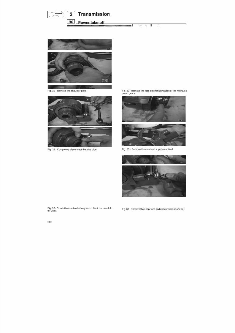
8/19/2019 Agrocompact f60 f70 f80 f90 Repair manual
http://slidepdf.com/reader/full/agrocompact-f60-f70-f80-f90-repair-manual 202/519
Fig. 32 - Remove the shoulder plate.
Fig. 34 - Completely disconnect the lube pipe.
Fig. 36 - Check the manifold oil ways and check the manifoldfor wear.
Fig. 33 - Remove the lube pipe for lubrication of the hydraulicpump gears.
Fig. 35 - Remove the clutch oil supply manifold.
Fig.37 - Remove the snaprings and checkforsigns ofwear.
202
36
3 Transmission
Power take-off
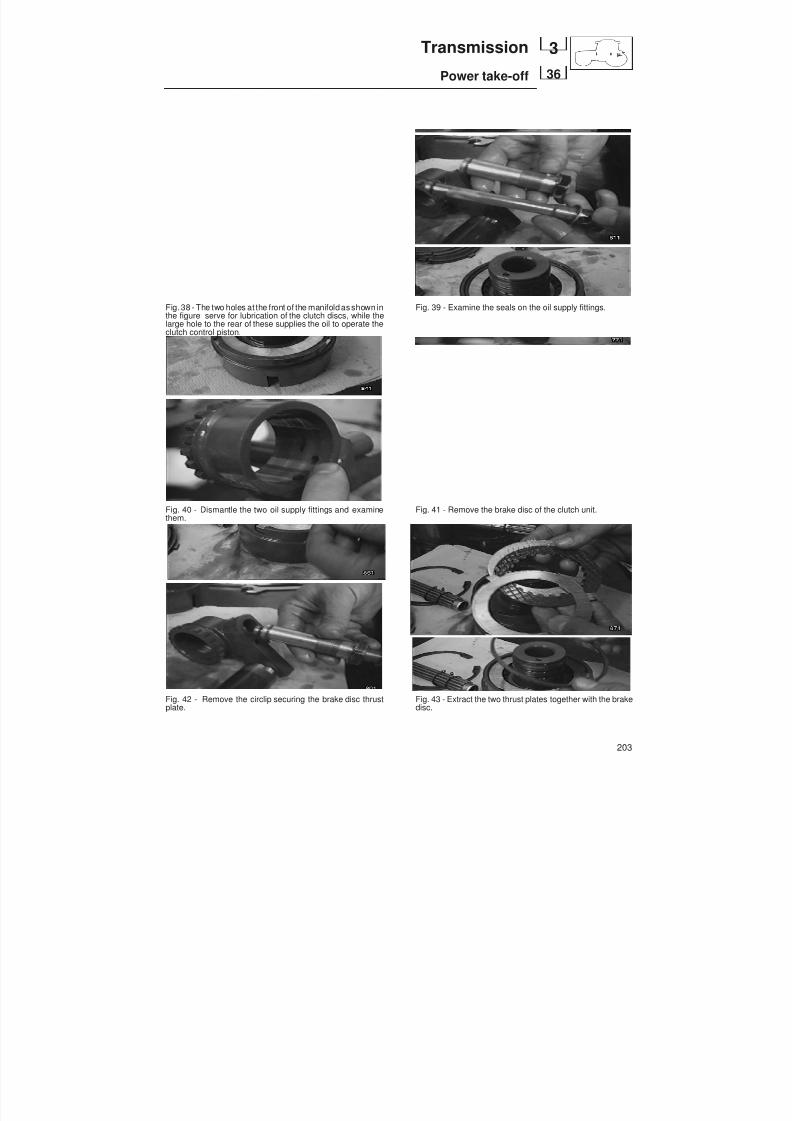
8/19/2019 Agrocompact f60 f70 f80 f90 Repair manual
http://slidepdf.com/reader/full/agrocompact-f60-f70-f80-f90-repair-manual 203/519
Fig. 38 - The two holes at the front of the manifold as shown inthe figure serve for lubrication of the clutch discs, while thelarge hole to the rear of these supplies the oil to operate theclutch control piston.
Fig. 40 - Dismantle the two oil supply fittings and examinethem.
Fig. 42 - Remove the circlip securing the brake disc thrustplate.
Fig. 39 - Examine the seals on the oil supply fittings.
Fig. 41 - Remove the brake disc of the clutch unit.
Fig. 43 - Extract the two thrust plates together with the brakedisc.
203
36
3Transmission
Power take-off

8/19/2019 Agrocompact f60 f70 f80 f90 Repair manual
http://slidepdf.com/reader/full/agrocompact-f60-f70-f80-f90-repair-manual 204/519
Fig. 44 - Examine the clutch brake disc pack. Fig. 45 - Check the three pressure pins for wear.
Diagnosing malfunctions
the clutch slips
the clutch fails to di -sengage
check the hydraulicsystem of the sole-noid valve block
check that the pi -ston slides freely
check the clutchplates for wear
incomplete controlvalve stroke, sole -noid valve faulty
piston stuck
replace the springsof incorrectly cali -brated valves
check the seals onthe piston and ma -nifold
eliminate any roug -hness preventingfree movement
replace the plates
check the controllinkage
check the plates
replace the piston
if necessary, repla -ce the defectiveparts
replace the defecti -ve parts
plates burned
plates jammed
replace the plates
eliminate any roug -hness preventingfree movement
204
36
3 Transmission
Power take-off
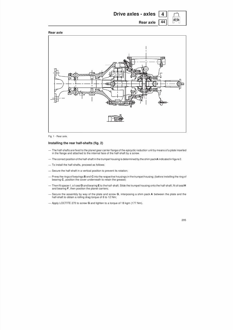
8/19/2019 Agrocompact f60 f70 f80 f90 Repair manual
http://slidepdf.com/reader/full/agrocompact-f60-f70-f80-f90-repair-manual 205/519

8/19/2019 Agrocompact f60 f70 f80 f90 Repair manual
http://slidepdf.com/reader/full/agrocompact-f60-f70-f80-f90-repair-manual 206/519
Fig. 2 - Fitting of rear stub axles.
Fig. 3 - Fitting of rear stub axles. Fig. 4 - Halfshaft securing plate.A - Planet carrier housingB - Spacer
206
44
4 Drive axles - axles
Rear axle

8/19/2019 Agrocompact f60 f70 f80 f90 Repair manual
http://slidepdf.com/reader/full/agrocompact-f60-f70-f80-f90-repair-manual 207/519
Fig. 5 - Fitting of bearing to halfshaft.
Fig. 6 - Fitting of O-ring to stub axles.
207
44
4Drive axles - axles
Rear axle

8/19/2019 Agrocompact f60 f70 f80 f90 Repair manual
http://slidepdf.com/reader/full/agrocompact-f60-f70-f80-f90-repair-manual 208/519
Removal and disassembly of the epicyclic reduction unit
Unscrew the three screws securing the planet carrier B ( Fig. 7) to the half-shaft.
Then remove the spacer and the flange, and recover the underlying shim pack.
Remove the epicyclic reduction unit and disassemble it into its component parts as follows:
1 - Using a hammer and drift, remove the pin securing journal A of planet gear B (Fig. 8).
2 - Withdraw the journal and remove the planet gear together with the roller cage and the two thrust washers.
3 - Remove bearing A from the flange of epicyclic reduction unit B , using a suitable puller (Fig. 9).
Fig. 7 - Removing the spacer.A - FlangeB - Planet carrier
Fig. 8 - Epicyclic reduction unit.A - JournalB - Planet Fig. 9 - Removing the bearing from the epicyclic reduction unit flange.
208
44
4 Drive axles - axles
Rear axle
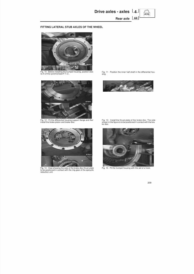
8/19/2019 Agrocompact f60 f70 f80 f90 Repair manual
http://slidepdf.com/reader/full/agrocompact-f60-f70-f80-f90-repair-manual 209/519
FITTING LATERAL STUB AXLES OF THE WHEEL
Fig. 10 - Before installing the trumpet housing, position slee -ve A of the synchronised P.T.O..
Fig. 12 - Fit the differential housing support flange and theninstall the brake piston and brake disc.
Fig. 14 - View showing the side of the brake disc thrust plateto be positioned in contact with the ring gear of the epicyclicreduction unit.
Fig. 11 - Position the inner half-shaft in the differential hou-sing.
Fig. 13 - Install the thrust plate of the brake disc. The sideshown in the figure is to be positioned in contact with the bra -ke disc.
Fig. 15 - Fit the trumpet housing with the aid of a hoist.
209
44
4Drive axles - axles
Rear axle

8/19/2019 Agrocompact f60 f70 f80 f90 Repair manual
http://slidepdf.com/reader/full/agrocompact-f60-f70-f80-f90-repair-manual 210/519
2WD extendible axle
General informationThe wide sideways front axle swinging obtained through excellent anchoring, not only makes it possible to operate thetractor nimbly on steep slopes but also permits the axle to be easily removed from the tractor when any repair is to beperformed. End play check is the only operation required on axle reassembly.
The telescopic-type axle is extremely rugged and enables the tread to be adapted to any work requirementswithout re -moving the hydrostatic steering cylinders.
Fig. 1 - Extendible front axle pivot system.
Tecnical specifications
front axle AGROCOMPACT F60 - 70F3 - 70F4 - F80 - F90
tread- minimum mm 993 803- base mm 1050 853- maximum mm 1271 1079toe-in mm 2 - 6 2 - 6wheel caster angle 3° 3°axle swinging angle 12° 12°tyre inflating pressure bar 2,4 2,4lubricating grease type NLGI 2 LITIO/Casteering angle 70° 70°
210
42
4 Drive axles - axles
2 W.D. extendible axle
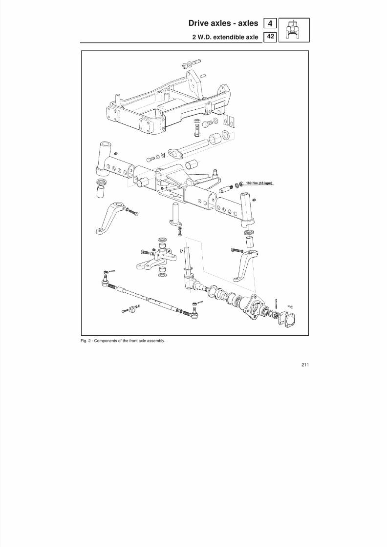
8/19/2019 Agrocompact f60 f70 f80 f90 Repair manual
http://slidepdf.com/reader/full/agrocompact-f60-f70-f80-f90-repair-manual 211/519
Fig. 2 - Components of the front axle assembly.
211
42
4Drive axles - axles
2 W.D. extendible axle

8/19/2019 Agrocompact f60 f70 f80 f90 Repair manual
http://slidepdf.com/reader/full/agrocompact-f60-f70-f80-f90-repair-manual 212/519
Removing the axle from the front support
Fig. 3 - Place some suitable vessels beneath the steering con -trol cylinders, then loosen unions A of control cylinders C fromhoses B side.
Fig. 5 - Using a hammer and light-alloy punch tap on rear endof pin A .
WARNING: Keep the two shim packs separated so that thecorrect position can be restored on reassembly.
Fig. 7 - Remove the axle from the front support by tapping afew times the axle centre portion with the hammer.Lower axle A very slowly and make sure that it does not touchother parts in the process, then remove shoulder rings B .
Fig. 4 - Loosen both securing screws of pin A to axle supportB .
Fig. 6 - Fig. 6 - By way of both levers A withdraw pin B for -ward and recover the shims interposed between flange andfront support.Ensure the securing pin surface shows no flattening, cra -king or chipping, replace the pin if necessary.
Fig. 8 - Ensurethatbushes A of the centre axle are not worn,checking for well-evident indentations, remove the bushesby hammer and punch if necessary.
212
42
4 Drive axles - axles
2 W.D. extendible axle
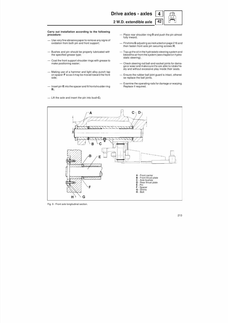
8/19/2019 Agrocompact f60 f70 f80 f90 Repair manual
http://slidepdf.com/reader/full/agrocompact-f60-f70-f80-f90-repair-manual 213/519
Carry out installation according to the followingprocedure:
— Use very fine abrasive paper to remove any signs ofoxidation from both pin and front support;
— Bushes and pin should be properly lubricated withthe specified grease type;
— Coat the front support shoulder rings with grease tomake positioning easier;
— Making use of a hammer and light alloy punch tapon spacer F so as it may be moved toward the front
side;
— Insert pin E into the spacer and fit frontshoulder ringB;
— Lift the axle and insert the pin into bush C;
Fig. 9 - Front axle longitudinal section.
— Place rear shoulder ring D and push the pin almostfully inward;
— Fit shims G adjusting as instructed on page 216 andthen fasten front axle pin securing screws H;
— Top up the oil in the hydrostatic steering system andbleedthe air from the system (see chapteron hydro -static steering).
— Check steering rod ball-and-socket joints for dama-ge or wear and make sure the are able to rotate fre -ely and without excessive play inside their seats.
— Ensure the rubber ball joint guard is intact, otherwi -
se replace the ball joints. — Examine the operating rods for damage or warping.
Replace if required.
A - Front carrierB - Front thrust plateC - Axle bushesD - Rear thrust plateE - PinF - SpacerG - ShimsH - Bolt
213
42
4Drive axles - axles
2 W.D. extendible axle

8/19/2019 Agrocompact f60 f70 f80 f90 Repair manual
http://slidepdf.com/reader/full/agrocompact-f60-f70-f80-f90-repair-manual 214/519
Fig. 10 - Removing the wheel hub.A - Tractor wheelB - Safety standC - Front axle
Fig. 11 - Removing the guard cover.A - Check pinB - GasketC - CoverD - HubE - Nut
Fig. 12- Using a pullerto removethe wheel hub.A - Wheel hub shaft pinB - Whole wheel hub
Fig. 13 - Wheel hub components.A - Cover D - SpacerB - Oil seal E - Ball bearing
C - Spacer F - HubG - Ball bearing
Wheel hub — Using a universal puller withdraw whole wheel hub B from pin,
(Fig. 12). — Make use of a suitable puller to remove front ball bearing G
(Fig. 13) . — Remove retaining ring A by prising, then using a proper puller
remove rear ball bearing E, (Fig.13).
— Before assembly coat bearings B and D and new retaining ringA with the recommended grease, (Fig. 14).Carefully insert retaining ring A using a hammer and light-alloypunch.
— Install wheel hub C onto pin G tapping slightly with the hammerfor proper bedding
— Tighten castellated nut E to the prescribed torque.Make sure the nut cut is duly aligned with the check pin hole inthe pin, otherwise tighten the nut furtherto make them coincideand re-install the check pin.
— Ensurewheel hub C end playis 0.12to 0.48mm with respect towheel shaft pin G .
Fig. 14 - Section view of the wheel hub.A - Oil seal E - Castellated nutB - Innner ball bearing F - Thrust plateC - Whel hub G - Whel shaft pinD - Outer ball bearing H - Space
214
42
4 Drive axles - axles
2 W.D. extendible axle

8/19/2019 Agrocompact f60 f70 f80 f90 Repair manual
http://slidepdf.com/reader/full/agrocompact-f60-f70-f80-f90-repair-manual 215/519
Inspections and checks
Clean bearings and the other parts carefully, then dry using com -pressed air.Carefully examine the bearings turning them slowly, if the bearingis sound no vibrations, noise nor slight jam-ups shall occur.
Carefully examine bearing raceand rolling member conditions en -suring no scoring, marking, grinding signs due to foreign matterabrasion are noticed, otherwise replace the bearing.
WARNING: Should a bearing be no longer serviceable, both theinternal and the external bearings must be replaced.
Make sure the wheel shaft has suffered no damage and the threa -ding is whole, replace if required.
Be sure no signs of oxidation are visible on the wheel shaft, if soremove with very fine abrasive paper.
Check the shaft for either warp or damage, if so replace the shaft.Carefully inspect the axial bearing making sure no grinding, sco -ring or marking are evident either on the rolling members or on thebearing races, otherwise replace the worn parts.
Check side axle upper and lower bushes A for wear, ascertainingthey still show evidence of the purpose-made indentations, other -wise replace.
Fig. 15 - Wheel pivot bushes.A - Clearance hole
Fig. 16 - Removing the steering lever.A - External steering leverB - GasketC - Wheel shaft
Fig. 17 - Removing thewheelpivot axial bearing.A - Wheel shaftB - Axial bearing
C - O-RingD - Axial bearing race
215
42
4Drive axles - axles
2 W.D. extendible axle

8/19/2019 Agrocompact f60 f70 f80 f90 Repair manual
http://slidepdf.com/reader/full/agrocompact-f60-f70-f80-f90-repair-manual 216/519
Fig. 18 - Track rods.A - SleeveB - Steering knuckle
Correct track rod assembly (Fig. 18)Rotate sleeve A around its axis so that knuckle B is in the positionshown in figure, i.e. make sure the knuckle working angle is 90°,then insert and tighten both the sleeve securing bolts.
End float adjustment (Fig. 19).Push the axle towards the rear and, using a feeler gauge, checkthat the maximum end float “G” does not exceed 0.4 mm.
If the end float exceeds this value, proceed as follows.
— Unscrew bolts E securing pin B to the front carrier A;
— Slightly move the pin and remove some of shims D to restorecorrect end float.
— Re-tighten bolts E and check end float again.
Fig. 19 - Adjusting the endfloat of the front axle .A - Front carrierB - PinC - Thrust plateD - ShimsE - Bolt
216
42
4 Drive axles - axles
2 W.D. extendible axle

8/19/2019 Agrocompact f60 f70 f80 f90 Repair manual
http://slidepdf.com/reader/full/agrocompact-f60-f70-f80-f90-repair-manual 217/519
FRONT-WHEEL DRIVE
Specificationsfront drive axle ratios
reduction gear-front-wheel drive 30 km/h 21/47 = 1/2.238140 km/h 28/47 = 1/1.6786
bevel gears 15/33 = 1/2.2000final epicyclic reducer (13/13+50)=1/4.8462total reduction 30 km/h 1/23.8618
40 km/h 1/17.8966mechanical ratio( number of front wheel turns for each rear wheel turn)
30 km/h 1.379040 km/h 1.3830
bevel gear teeth backlash mm 0.15 ÷ 0.20front drive axle end play mm 0.1 ÷ 0.4front drive axle swinging 10°steering angle 50°toe-in see specification table here belowwheel caster angle 7°camber 1°Check value for the adjusting the bevel gears mm 1
Fig. 1 - Measuring front wheel toe-in and front wheel geometry.
Adjusting toe-inAdjustthe front wheel tie rod soas the difference A-B shown in figure1 is:
wheel rim keying diameter A-B mm2RM 4RM
up to 20" (508 mm) 2 to 6 0±2from 20’’ to 30" (509 ÷ 762 mm) 2 to 6 0±3over 30" 2 to 6 0±3.5
Adjusting steering anglesMake sure the front drive wheel steering angle is as specified in the tableabove.Otherwise adjust by way of the special setscrews or spacers. Fig. 2 -Front-wheel drive steering angles.
217
43
4Drive axles - axles
4 W.D. front axle
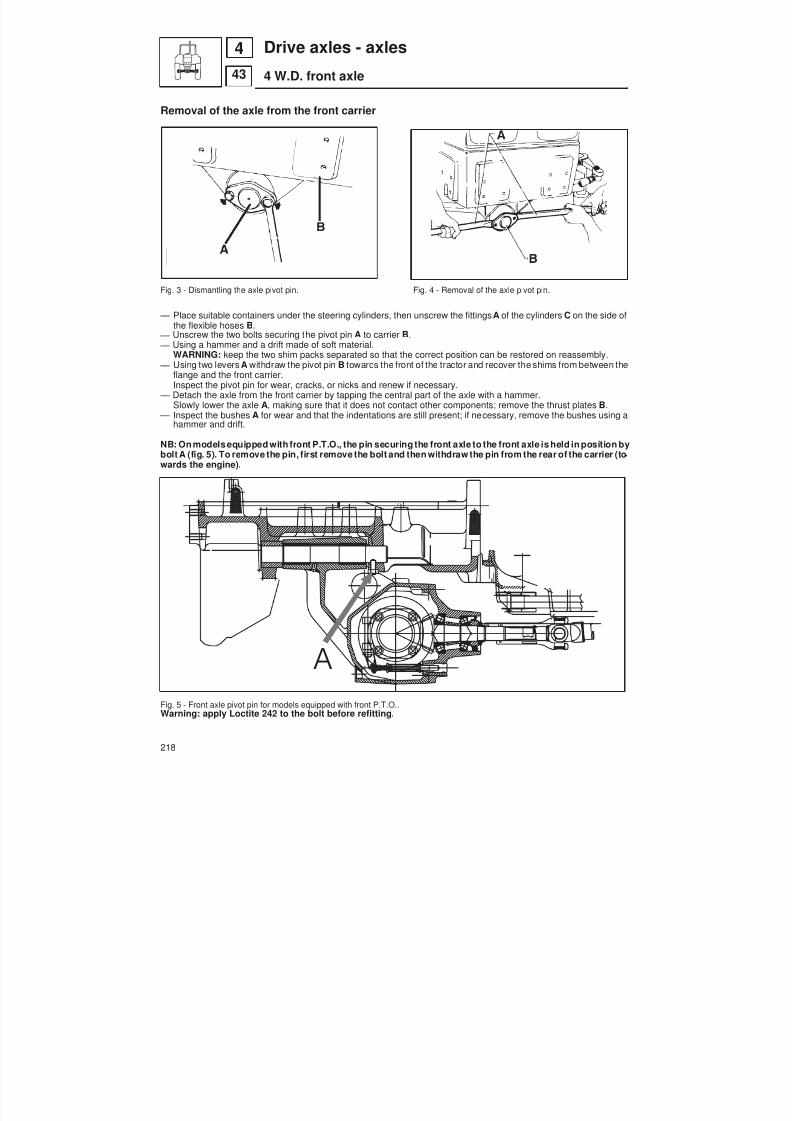
8/19/2019 Agrocompact f60 f70 f80 f90 Repair manual
http://slidepdf.com/reader/full/agrocompact-f60-f70-f80-f90-repair-manual 218/519
Removal of the axle from the front carrier
Fig. 3 - Dismantling the axle pivot pin. Fig. 4 - Removal of the axle pivot pin.
— Place suitable containers under the steering cylinders, then unscrew the fittings A of the cylinders C on the side ofthe flexible hoses B .
— Unscrew the two bolts securing the pivot pin A to carrier B . — Using a hammer and a drift made of soft material.
WARNING: keep the two shim packs separated so that the correct position can be restored on reassembly. — Using two levers A withdraw the pivot pin B towards the front of the tractor and recover the shims from between the
flange and the front carrier.Inspect the pivot pin for wear, cracks, or nicks and renew if necessary.
— Detach the axle from the front carrier by tapping the central part of the axle with a hammer.
Slowly lower the axle A , making sure that it does not contact other components; remove the thrust plates B . — Inspect the bushes A for wear and that the indentations are still present; if necessary, remove the bushes using ahammer and drift.
NB: On models equipped with front P.T.O., the pin securing the front axle to the front axle is held in position bybolt A (fig. 5). To remove the pin, first remove the bolt and then withdraw the pin from the rear of the carrier (to -wards the engine).
Fig. 5 - Front axle pivot pin for models equipped with front P.T.O..Warning: apply Loctite 242 to the bolt before refitting.
218
43
4 Drive axles - axles
4 W.D. front axle
d
0.010.0978.0
23.1
A

8/19/2019 Agrocompact f60 f70 f80 f90 Repair manual
http://slidepdf.com/reader/full/agrocompact-f60-f70-f80-f90-repair-manual 219/519
Fig. 6 - Front axle - longitudinal section.
Bloccaggio differenziale meccanico.
Bloccaggio differenziale elettroidraulico.
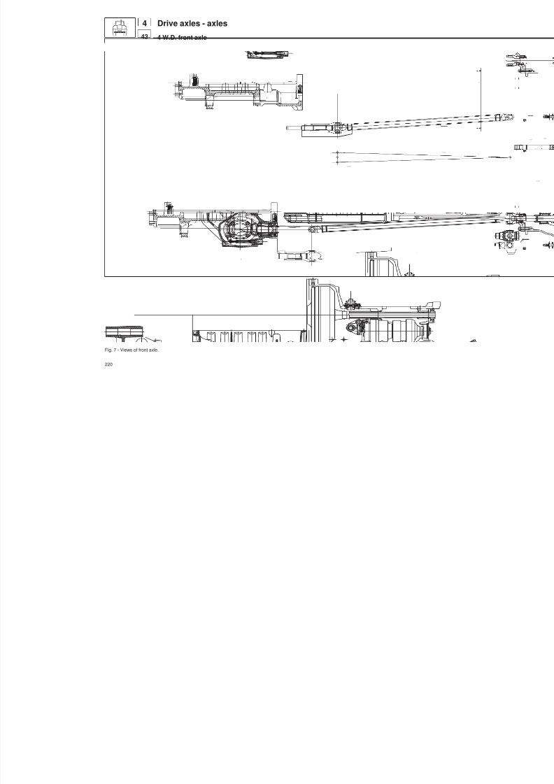
8/19/2019 Agrocompact f60 f70 f80 f90 Repair manual
http://slidepdf.com/reader/full/agrocompact-f60-f70-f80-f90-repair-manual 220/519
Fig. 7 - Views of front axle.
220
Drive axles - axles
4 W.D. front axle
443
0.010.0979.2
d
d
0.010.0974.3
0.010.0978.0
Lin e a d e i c e n triC en ter lin e
23.1
30.63
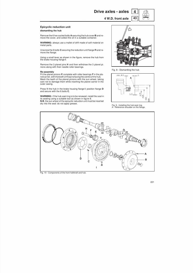
8/19/2019 Agrocompact f60 f70 f80 f90 Repair manual
http://slidepdf.com/reader/full/agrocompact-f60-f70-f80-f90-repair-manual 221/519
Epicyclic reduction unitdismantling the hub
Remove the 6 hex socket bolts A securing the hub cover B and re-move the cover, and collect the oil in a suitable container.
WARNING: always use a mallet of drift made of soft material onmetal parts.
Unscrew the 6 bolts C securing the reduction unit flange D and re -move the flange.
Using a small lever as shown in the figure, remove the hub fromthe brake housing flange I.
Remove the 3 planet pins H and then withdraw the 3 planet pi -nions along with their needle roller bearings.
Re-assemblyFit the planet pinions E complete with roller bearings F in the pla -netcarrier, with theteeth of thepinsfacing the centre of the hub.Mesh the teeth of the planet pinions with the sun wheel, takingcare not to damage them while inserting the planet carrier in theouter casing.
Press fit the hub in the brake housing flange I; position flange Dand secure with the 6 bolts C .
WARNING: if the hub seal ring is to be renewed, install the seal in
its seating using a suitable tool as shown in figure 8.N.B. the sun wheelof the epicyclic reduction unit must be inserteddry into the seal: do not apply grease.
Fig. 10 - Components of the front halfshaft and hub.
Fig. 8 - Dismantling the hub
Fig. 9 - Installing the hub seal ring.A - Reference shoulder on the flange.
221
43
4Drive axles - axles
4 W.D. front axle

8/19/2019 Agrocompact f60 f70 f80 f90 Repair manual
http://slidepdf.com/reader/full/agrocompact-f60-f70-f80-f90-repair-manual 222/519
Fig. 11 - Fixing the halfshaft for assembly of theepicyclic reduction unitA - Spider
Fig. 12 - Checking wheel hub clearance.A - LeverB - ScrewsC - Pack of shimsD - ScrewsE - 0.5 mm shim.
The following procedure should be observed on re -assembly
BrakesReplace the brake control piston O-rings and insert piston in itsseat with the oil grooves turned outwards.
Final epicyclic reducerInstall the final epicyclic reducer holding the axle shaft in positionas shown in figure 12 by prising outwards on cross journal A; inor -der to prevent the axle shaft from moving inwards.
Axle shaftsWhen inserting the axle shaft pay attention not to damage the rol -ler bearing or the seal ring.
The axle shaft end shouldbe correctly introducedinto thedifferen -tial gear planetaries.Make sure the axle shaft is free to rotate without any hindrance.
ForksAfter installing the bearings and the dust rings mount the fork byplacing one 0.5 mm shimunder the lower pin, then fit the pin, use ahammer if necessary, finally tighten the securing screws. Fit apack of shims thicker than the one taken on removal under the up -per pin. Install the pin tightening the securing screws.
Adjusting the preloading of the hub carrier bearings
Loosen the screws and install a shim pack of thickness 0.5mm un -der the lower pivot pin and a shim pack of greater thickness thanthat previously installed under the upper pivot pin.In the pack of shims to be used for adjustment it is always advisa-ble to group more shims in one: as an example, it is better one 0,2mm shim be used instead of two 0.1 mm shims.
Fit no. 5.9030.267.0 magnetic base with no. 5.9030.272.0 cente -simal dial gauge onto the drive axle and then place the gauge fee-ler perpendicularly to the lower pin, close to centre, and set tozero.
Using lever A as shown in figure, move the fork fully upwards andread the clearance on the gauge dial.
Loosen the two screws B and remove shims from pack C so thatanyclearance maybe taken up without preloading thebearings.
WARNING: The clearance amount should be reduced graduallyby repeating reading with thedialgauge each time so that the bea -rings are not preloaded.After all clearance has been taken up, remove a 0.10 to 0.15 mmshim pack, so that a correct bearing preloadingcanbe obtained.Tighten screws B and D to the specified torque.
After correctly performing the adjustment, ensure the shaft taperroller bearing slide in their seats freely, even though a slight prelo -ading is felt.
Grease the hub bearings.
222
43
4 Drive axles - axles
4 W.D. front axle

8/19/2019 Agrocompact f60 f70 f80 f90 Repair manual
http://slidepdf.com/reader/full/agrocompact-f60-f70-f80-f90-repair-manual 223/519
Side hubs
Disassemble the twin universal joints if required, keeping to the following procedure:
— Remove both snap rings A from one cross journal B . A non-ferrous metal hammer and punch may help in carryingout this operation, (see Fig. 13).
— Fix the joint fork in a vice provided with protective jaws.
— Tap with a hammer on wheel shaft fork A (see Fig. 15), so that the bearing may be removed upwards from its seat infork A. Separate cross joint D from the fork.
— Following the same procedure separate the cross joint from the universal joint fork as well as from the axle shaftfork.
Fig. 13 - Twin universal joint.A - Snap ringB - Twin universal joint cross journal
Fig. 14 - Axle shaft twin-type universal joint bearing.
A - RollersB - Dust rings
Fig. 15 - Disassembling the twin-type universal joint from the axle shaft.A - Wheel shaft forksB - Roller bearingC - Roller bearingD - Cross joint
223
43
4Drive axles - axles
4 W.D. front axle

8/19/2019 Agrocompact f60 f70 f80 f90 Repair manual
http://slidepdf.com/reader/full/agrocompact-f60-f70-f80-f90-repair-manual 224/519
Fitting the front axle studs
Fit the 2 studs code 2.0432.161.7 in holes 1and 2 in the figure.
Fig. 16 - Fitting the front axle studs.
Axle shaftsCheck for excessive wear: splines should not be nicked and permit a free gear movement.Spider forks should not be warped and bearings should slide freely.
GearsMake sure all gear toothing is neither worn nor damaged, teeth should work on the whole contact face.
BearingsExamine bearings for proper working conditions, ensure they show neither excessive radial nor end play.Pressing the bearings by hand and simultaneously turning them in both directions, they should slide freely.
TIGHTENING TORQUESBefore tightening, all screws should be degreased and cleaned
kgm NmDifferential/bevel gear securing screws 7,5 73Bevel pinion fixing nut 21 ÷ 23 206 ÷ 226Bearing holding flange securing screws 9,7 95Hydraulic cylinder fixing pin 5,5 54Ball-and-socket joint castellated nuts 12 119Transmission shaft flange securing screws * 5 49Differential half case securing screws 11.5 ÷ 12 113 ÷ 118* Coat the nut with a small amount of Loctite 242.
Check periodically that the wheel bolts are correctly tightened.Front wheel bolts 2RM (M20x1.5) 50 kgm (490 Nm);Front wheel bolts 4RM (M18x1.5) 36.8 kgm (360 Nm)Rear wheel bolts (M20x1.5) 50 kgm (490 Nm).
224
43
4 Drive axles - axles
4 W.D. front axle
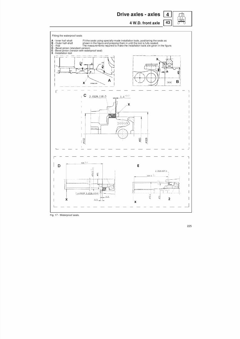
8/19/2019 Agrocompact f60 f70 f80 f90 Repair manual
http://slidepdf.com/reader/full/agrocompact-f60-f70-f80-f90-repair-manual 225/519
Fitting the waterproof seals
A - Inner half-shaft Fit the seals using specially-made installation tools, positioning the seals asB - Outer half-shaft shown in the figure and pressing them in until the tool is fully seated.C - Hub The measurements required to make the installation tools are given in the figure.D - Bevel pinion (standard version)E - Bevel pinion (version with waterproof seal)X - Installation tool
Fig. 17 - Waterproof seals.
225
43
4Drive axles - axles
4 W.D. front axle
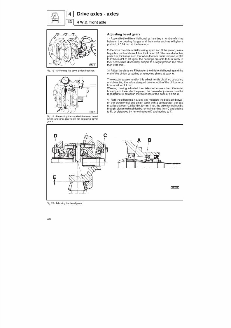
8/19/2019 Agrocompact f60 f70 f80 f90 Repair manual
http://slidepdf.com/reader/full/agrocompact-f60-f70-f80-f90-repair-manual 226/519
Fig. 18 - Shimming the bevel pinion bearings.
Fig. 19 - Measuring the backlash between bevel
pinion and ring gear teeth for adjusting bevelgears.
Fig. 20 - Adjusting the bevel gears.
Adjusting bevel gears
1 - Assemble the differential housing, inserting a number of shimsbetween the bearing flanges and the carrier such as will give apreload of 0.04 mm at the bearings.
2 -Remove the differential housing again and fit the pinion, inser -ting a first pack of shims A to a thickness of 0.50 mm and a furtherpack B of thickness such that when the lock nut is torqued to 206to 226 Nm (21 to 23 kgm), the bearings are able to turn freely intheir seats while discernibly subject to a slight preload (no morethan 0.04 mm).
3 - Adjust the distance E between the differential housing and theend of the pinion by adding or removing shims at pack A .
The exact measurement for this adjustment is obtained by addingor subtracting the value stamped on one tooth of the pinion to orfrom a value of 1 mm.Warning: having adjusted the distance between the differentialhousing and the end of the pinion, the preload adjustment must berepeated to re-establish the thickness of the pack of shims B .
4 - Refit the differential housing and measure the backlash betwe -en the crownwheel and pinion teeth with a comparator: the gapmust be between0.15 and0.20 mm; if not, the crownwheelcan bebrought closer to the pinion by removing shims from C and addingto D , or distanced by removing from D and adding to C .
226
43
4 Drive axles - axles
4 W.D. front axle
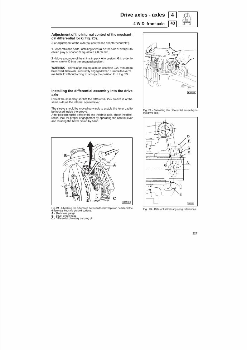
8/19/2019 Agrocompact f60 f70 f80 f90 Repair manual
http://slidepdf.com/reader/full/agrocompact-f60-f70-f80-f90-repair-manual 227/519
Adjustment of the internal control of the mechani -cal differential lock (Fig. 23).(For adjustment of the external control see chapter “controls”).
1 - Assemble the parts, installing shims A on the side of circlip B toobtain play of spacer C equal to 0 ± 0.05 mm.
2 - Move a number of the shims in pack A to position G in order tomove sleeve D into the engaged position.
WARNING - shims of packs equal to or less than 0.20 mm are tobe moved. Sleeve D is correctly engaged when it is able to overco -me balls F without forcing to occupy the position E in Fig. 23.
Installing the differential assembly into the driveaxleSwivel the assembly so that the differential lock sleeve is at thesame side as the internal control lever.
The sleeve should be moved outwards to enable the lever pad tobe housed inside the groove.After positioning the differential into the drive axle, check the diffe -rential lock for proper engagement by operating the control leverand rotating the bevel pinion by hand.
Fig. 21 - Checking the difference between the bevel pinion head and thedifferential housing ground surface.A - Thickness gaugeB - Bevel pinion headC - Differential planetary carrying pin
Fig. 22 - Swivelling the differential assembly inthe drive axle.
Fig. 23 - Differential lock adjusting references.
227
43
4Drive axles - axles
4 W.D. front axle
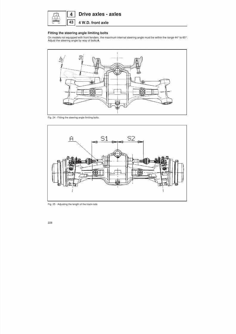
8/19/2019 Agrocompact f60 f70 f80 f90 Repair manual
http://slidepdf.com/reader/full/agrocompact-f60-f70-f80-f90-repair-manual 228/519
Fitting the steering angle limiting boltsOn models not equipped with front fenders, the maximum internal steering angle must be within the range 44°to 60°.Adjust the steering angle by way of bolts A .
Fig. 24 - Fitting the steering angle limiting bolts
Fig. 25 - Adjusting the length of the track rods
228
43
4 Drive axles - axles
4 W.D. front axle
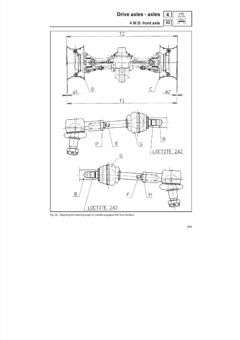
8/19/2019 Agrocompact f60 f70 f80 f90 Repair manual
http://slidepdf.com/reader/full/agrocompact-f60-f70-f80-f90-repair-manual 229/519
Fig. 26 - Adjusting the steering angle on models equipped with front fenders.
229
43
4Drive axles - axles
4 W.D. front axle
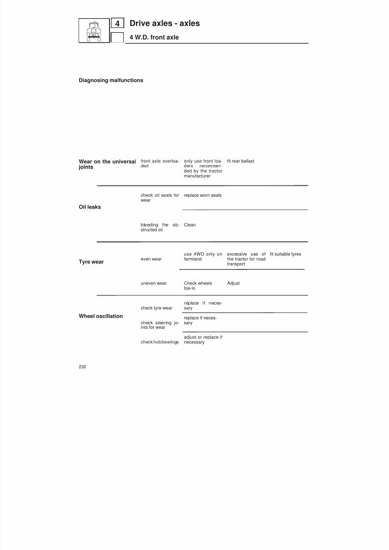
8/19/2019 Agrocompact f60 f70 f80 f90 Repair manual
http://slidepdf.com/reader/full/agrocompact-f60-f70-f80-f90-repair-manual 230/519
Diagnosing malfunctions
Wear on the universaljoints
Oil leaks
Tyre wear
Wheel oscillation
front axle overloa -ded
check oil seals forwear
bleeding the ob-structed oil
even wear
uneven wear
check tyre wear
check steering jo-ints for wear
check hubbearings
only use front loa -ders recommen -ded by the tractormanufacturer
replace worn seals
Clean
use 4WD only onfarmland
Check wheelstoe-in
replace if neces -sary
replace if neces -sary
adjust or replace ifnecessary
fit rear ballast
excessive use ofthe tractor for roadtransport
Adjust
fit suitable tyres
230
4 Drive axles - axles
4 W.D. front axle

8/19/2019 Agrocompact f60 f70 f80 f90 Repair manual
http://slidepdf.com/reader/full/agrocompact-f60-f70-f80-f90-repair-manual 231/519
Brakes
General informationThe service brakes are located between gearbox and finalepicyclic reducers and assure a precise and safe braking action.In addition, the four-wheel drive tractor models are also equippedwith integral braking system providing braking on all tractor whe -els.
The braking systemis sintered-lining, oil-immerseddisk type. Theright-hand brake control is completely independent from theleft-hand brake control; this allows the tractor turning radius to beconveniently reduced (this operation is only possible when wor -king on farm land and never during transport operations on publicroads). The braking system is provided with the “SEPARATE
BRAKES” valve which enables the front wheel braking to be ex -cluded.
Each brake pedal controls a hydraulic pump which delivers oil un -der pressure to a disk thrust plate, which causes the brake disk tolock.Operating both brake pedals simulteneously by coupling themwith the special joining latch, opens an oil duct connecting bothhydraulic circuits to balance the baking pressure on the wheels.Brake maintenance is limited to an easy adjustment and a systemair bleeding if necessary.
The parking brake has mechanical control and acts on transmis -
sion downstream of gearbox. Pulling the control lever upwardsmakes the brake disks pack together thus locking the shaft beingconstantly meshed with the wheels.Maintenance is very easy and consists of replacing the frictionpads when worn or adjusting the control lever travel.
Specifications
Fig. 1 - Front service brakes.
Fig. 2 - Parking brake parts.
service brakes front rear2RM 4RM
Manufacturer SAME - DEUTZ FAHR GROUPbrake type oil-immersed disks
number of disks each brake 2 (each side) 1 (each side) 1 (each side)brake disk outside diameter mm 223,4 223,4 280original brake disk thickness mm 4,80 4,80 7brake disk minimum thicknessallowable mm 4,40 4,40 6brake pedal free travel mm 40braking piston max. Play mm 1,15hydraulic pump type benditalia Ø 1’’parking brakebrake type oil-immersed disksnumber of braking pads double braking surface n°2
single braking surface n°2original braking pad thickness double mm 5
single mm 3,5braking pad minimumthickness allowable double mm 4,3
single mm 3,2brake disk number 3parking brake control lever travel mm 100
231
54
5Vehicle
Brakes

8/19/2019 Agrocompact f60 f70 f80 f90 Repair manual
http://slidepdf.com/reader/full/agrocompact-f60-f70-f80-f90-repair-manual 232/519
Fig. 3 - Brake control assembly parts.
Fig. 4 - Brake pump control unit.
Hydraulic pump
Disassebly and checking procedure
Referring to fig 4: — Remove guard boot A , take snap ring B and withdraw rod C
along with the support disk.
Referring to fig 6: — Fix the pump in a vice provided with protective jaws and pu -
shing pistons into the pump partly, as shown in figure 6, loosenthe piston retaining screws and then remove the pistons toget -her with the spring down below.
232
54
5 Vehicle
Brakes

8/19/2019 Agrocompact f60 f70 f80 f90 Repair manual
http://slidepdf.com/reader/full/agrocompact-f60-f70-f80-f90-repair-manual 233/519
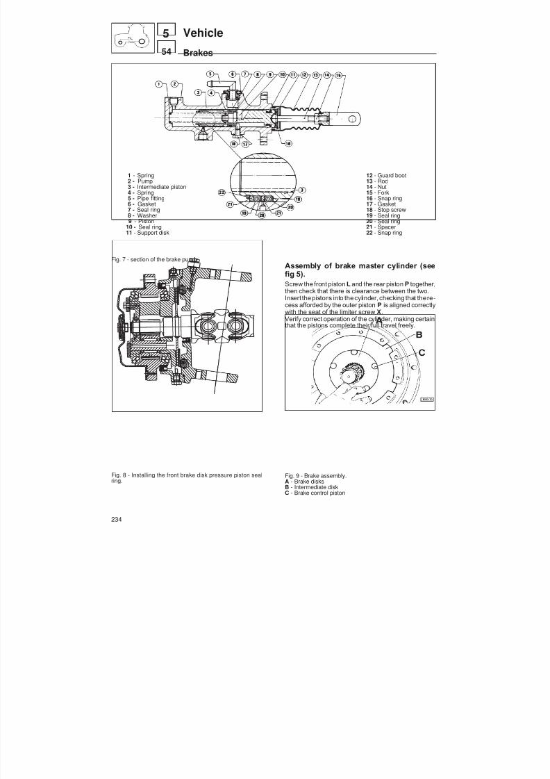
8/19/2019 Agrocompact f60 f70 f80 f90 Repair manual
http://slidepdf.com/reader/full/agrocompact-f60-f70-f80-f90-repair-manual 234/519
1 - Spring2 - Pump
3 - Intermediate piston4 - Spring5 - Pipe fitting6 - Gasket7 - Seal ring8 - Washer9 - Piston
10 - Seal ring11 - Support disk
Fig. 7 - section of the brake pump.
Fig. 8 - Installing the front brake disk pressure piston sealring.
12 - Guard boot13 - Rod
14 - Nut15 - Fork16 - Snap ring17 - Gasket18 - Stop screw19 - Seal ring20 - Seal ring21 - Spacer22 - Snap ring
Assembly of brake master cylinder (seefig 5).Screw the front piston L and the rear piston P together,then check that there is clearance between the two.Insert thepistons into thecylinder, checking that there -cess afforded by the outer piston P is aligned correctlywith the seat of the limiter screw X.Verify correct operation of the cylinder, making certainthat the pistons complete their full travel freely.
Fig. 9 - Brake assembly.A - Brake disksB - Intermediate diskC - Brake control piston
234
54
5 Vehicle
Brakes
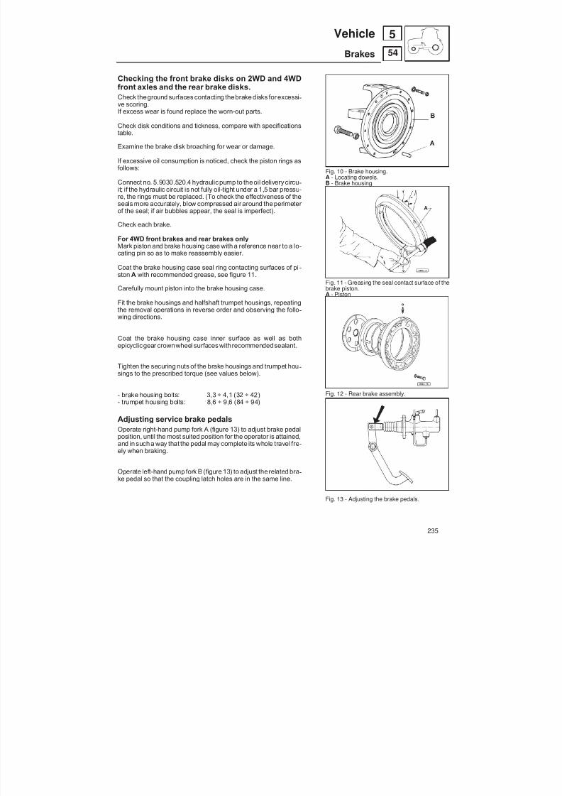
8/19/2019 Agrocompact f60 f70 f80 f90 Repair manual
http://slidepdf.com/reader/full/agrocompact-f60-f70-f80-f90-repair-manual 235/519
Checking the front brake disks on 2WD and 4WDfront axles and the rear brake disks.Check theground surfaces contacting thebrake disks for excessi -ve scoring.If excess wear is found replace the worn-out parts.
Check disk conditions and tickness, compare with specificationstable.
Examine the brake disk broaching for wear or damage.
If excessive oil consumption is noticed, check the piston rings asfollows:
Connect no. 5.9030.520.4 hydraulic pump to theoil delivery circu -
it; if the hydraulic circuit is not fully oil-tight under a 1,5 bar pressu -re, the rings must be replaced. (To check the effectiveness of theseals more accurately, blow compressed air around theperimeter of the seal; if air bubbles appear, the seal is imperfect).
Check each brake.
For 4WD front brakes and rear brakes onlyMark piston and brake housing case with a reference near to a lo -cating pin so as to make reassembly easier.
Coat the brake housing case seal ring contacting surfaces of pi -ston A with recommended grease, see figure 11.
Carefully mount piston into the brake housing case.
Fit the brake housings and halfshaft trumpet housings, repeatingthe removal operations in reverse order and observing the follo -wing directions.
Coat the brake housing case inner surface as well as bothepicyclicgear crownwheel surfaces withrecommendedsealant.
Tighten the securing nuts of the brake housings and trumpet hou -sings to the prescribed torque (see values below).
- brake housing bolts: 3,3 ÷ 4,1 (32 ÷ 42)- trumpet housing bolts: 8,6 ÷ 9,6 (84 ÷ 94)
Adjusting service brake pedalsOperate right-hand pump fork A (figure 13) to adjust brake pedalposition, until the most suited position for the operator is attained,and in such a way that the pedal may complete its whole travel fre -ely when braking.
Operate left-hand pump fork B (figure 13) to adjust therelated bra -ke pedal so that the coupling latch holes are in the same line.
Fig. 10 - Brake housing.A - Locating dowels.B - Brake housing
Fig. 11 - Greasing the seal contact surface of the
brake piston.A - Piston
Fig. 12 - Rear brake assembly.
Fig. 13 - Adjusting the brake pedals.
235
54
5Vehicle
Brakes

8/19/2019 Agrocompact f60 f70 f80 f90 Repair manual
http://slidepdf.com/reader/full/agrocompact-f60-f70-f80-f90-repair-manual 236/519
Fig. 14 - Rear brakes for 2WD front axle.
Fig. 15 - Parking brake inspection window
Correct installation of inspection cover for parkingbrake discs
Before fitting the cover, apply the sealantPIANERMETIC 510 to the surfaces in contact with thegearbox (marked A in thefigure), then tighten the threescrews marked B in the figure to a torque of 5.8 kgm(55 Nm).Check that with the control lever positioned at angle of approx. 40° relative to the horizontal, the brake play isthat indicated in the figure. If the play exceeds this va -lue, replace disc C with the single braking surface witha discs with a double braking surface (to recover 1mmof play). Alternatively insert a shim (code 009.9648.0)between the disc C and the reaction plate (to recover 2mm of play).
Checking parking brake padsExamine the brake pads for wear. If brake pad thic -kness is out of specifications these shall be replaced.Brake pads can be dismounted after removing the lo -wer brake pad lockpin, this permits access through thecover placed under the gearbox to be gained.Before installing new brake pads, check lockpin sealring conditions, replace if necessary.
236
54
5 Vehicle
Brakes

8/19/2019 Agrocompact f60 f70 f80 f90 Repair manual
http://slidepdf.com/reader/full/agrocompact-f60-f70-f80-f90-repair-manual 237/519
Fig. 16 - Parking brake assembly; ( A- Brakes disk).
Bleeding air from the brake hydraulic systemOperate as follows:
— unhook pedals by removing the coupling latch: afterwards pla -ce the “SEPARATE BRAKES” valve control in OFF position;
— operate the right-hand brake pedal several times; — by holding the pedal in fully depressed position, slightly un -
screw and tighten soon after the relevant air bleeding valve onthe rear right-hand brake.
This operation should be repeated until such time as the oil flowsout of the bleeding valve without air bubbles.
Repeat the same procedure on the front right-hand brake by ac -ting on the related air bleeding valve.
Follow the same procedure on the front and rear left-hand brakesmaking use of the related air bleeding valves.
We recommend that only oil with internationalspecifications ATF DEXRON II I used in the bra -king system.
Fig. 17 - Bleeding the air from the rear servicebrake hydraulic system.
Fig. 18 - Bleeding the air from the front servicebrake hydraulic system.
237
54
5Vehicle
Brakes

8/19/2019 Agrocompact f60 f70 f80 f90 Repair manual
http://slidepdf.com/reader/full/agrocompact-f60-f70-f80-f90-repair-manual 238/519
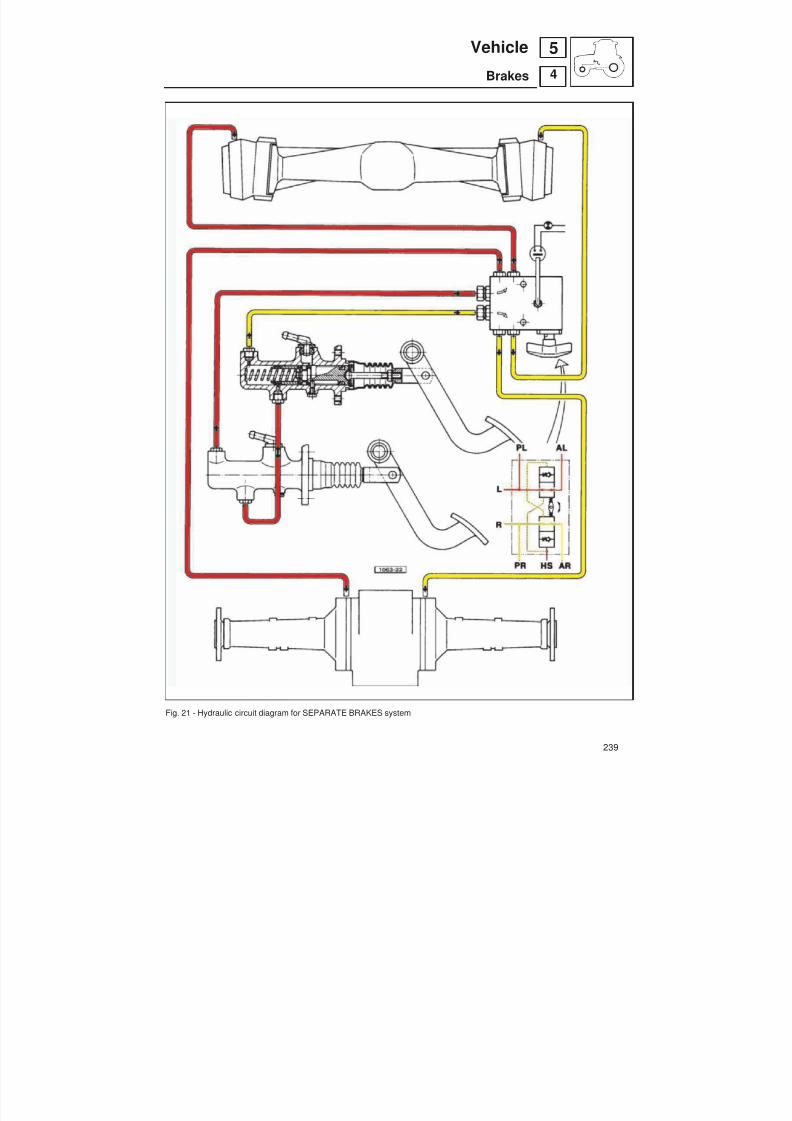
8/19/2019 Agrocompact f60 f70 f80 f90 Repair manual
http://slidepdf.com/reader/full/agrocompact-f60-f70-f80-f90-repair-manual 239/519
Fig. 21 - Hydraulic circuit diagram for SEPARATE BRAKES system
239
4
5Vehicle
Brakes
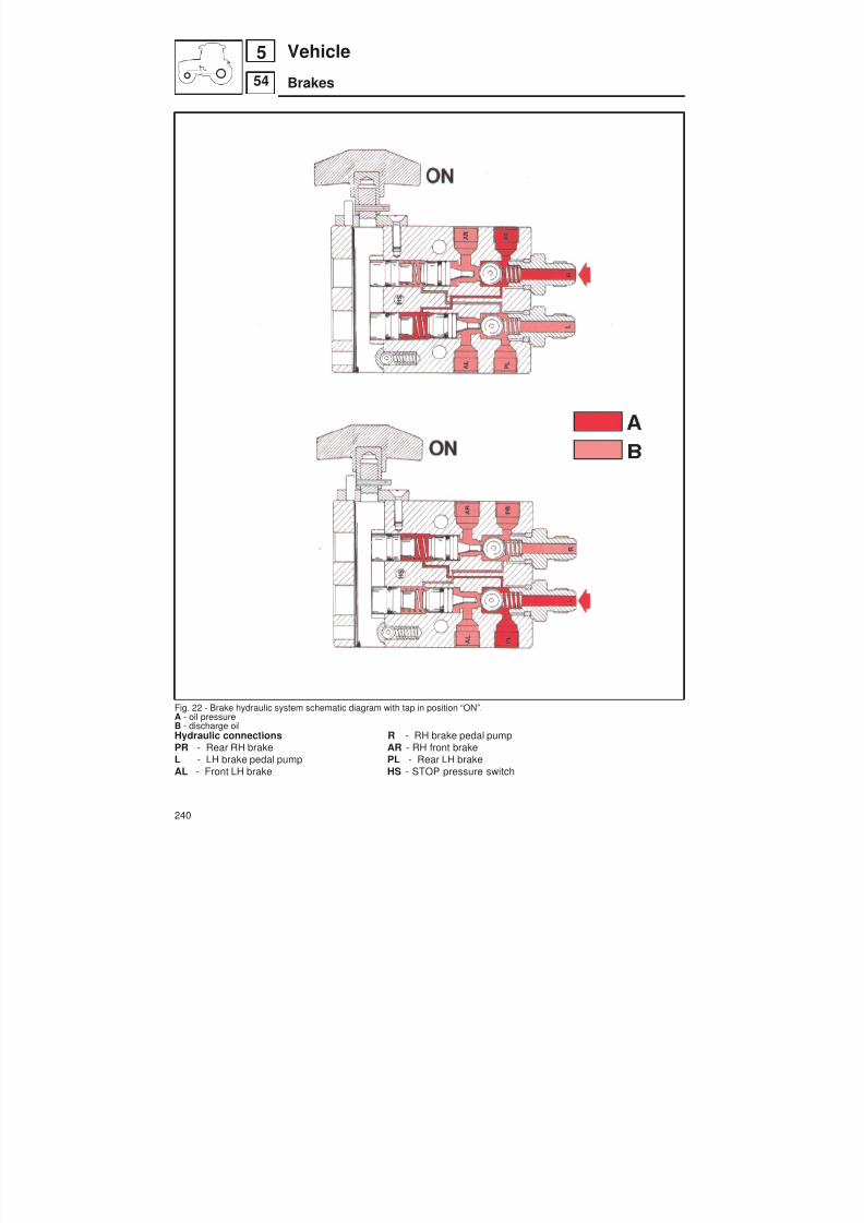
8/19/2019 Agrocompact f60 f70 f80 f90 Repair manual
http://slidepdf.com/reader/full/agrocompact-f60-f70-f80-f90-repair-manual 240/519
Fig. 22 - Brake hydraulic system schematic diagram with tap in position “ON”.A - oil pressureB - discharge oilHydraulic connections R - RH brake pedal pumpPR - Rear RH brake AR - RH front brakeL - LH brake pedal pump PL - Rear LH brakeAL - Front LH brake HS - STOP pressure switch
240
54
5 Vehicle
Brakes
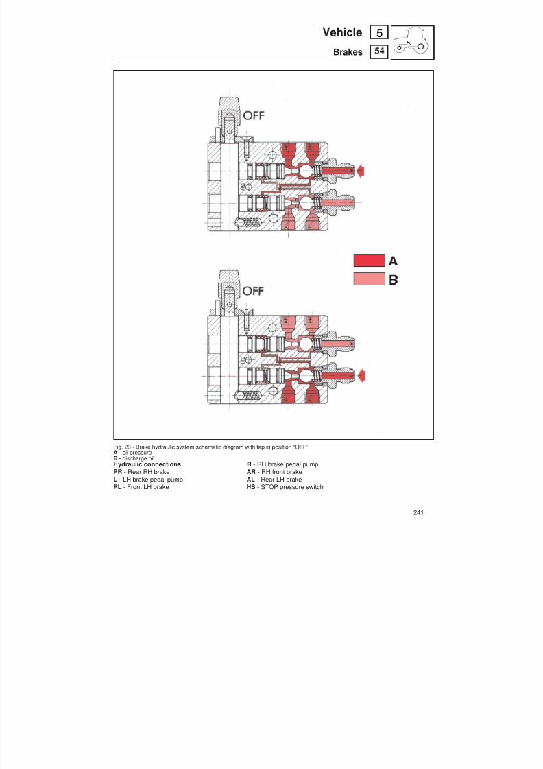
8/19/2019 Agrocompact f60 f70 f80 f90 Repair manual
http://slidepdf.com/reader/full/agrocompact-f60-f70-f80-f90-repair-manual 241/519
Fig. 23 - Brake hydraulic system schematic diagram with tap in position “OFF”A - oil pressureB - discharge oil
Hydraulic connections R - RH brake pedal pumpPR - Rear RH brake AR - RH front brakeL - LH brake pedal pump AL - Rear LH brakePL - Front LH brake HS - STOP pressure switch
241
54
5Vehicle
Brakes

8/19/2019 Agrocompact f60 f70 f80 f90 Repair manual
http://slidepdf.com/reader/full/agrocompact-f60-f70-f80-f90-repair-manual 242/519
Diagnosing malfunctions
poor braking
uneven braking
noisy braking
make sure no air isinside system
check for correctadjustment
check brake disksfor wear
make sure the re -commended oiltype is used
check for correctadjustment
make sure the re-commended oiltype is used
check brakes diskfor wear
bleed the air
adjust
replace
bleed the air
replace
adjust
replace
replace
242
54
5 Vehicle
Diagnosing malfunctions
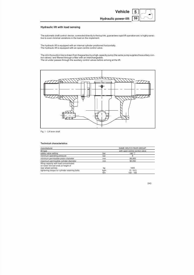
8/19/2019 Agrocompact f60 f70 f80 f90 Repair manual
http://slidepdf.com/reader/full/agrocompact-f60-f70-f80-f90-repair-manual 243/519
Hydraulic lift with load sensing
The automatic draft control device, connecteddirectly to the top link, guarantees rapid lift operation and is highly sensi -tive to even minimal variations in the load on the implement.
The hydraulic lift is equipped with an internal cylinder positioned horizontally.The hydraulic lift is equipped with an open-centre control valve.
The oil in thesuction line is drawn from thegearbox by a high-capacity pump(the same pump supplies theauxiliary con -trol valves) ‘and filtered through a filter with an interchangeable.The oil under passes through the auxiliary control valves before arriving at the lift.
Fig. 1 - Lift lever shaft
Technical characteristics
manufacturer SAME DEUTZ-FAHR GROUPlift type with open-centre control valvesafety valve setting bar 190 0
10+
minimum operating pressure bar 8minimum permissible piston diameter mm 89,900maximum permissible cylinder diameter mm 90,050lifting capacity with load concentrated
on lower link ball ends at height ofrear wheel centres kg 1600tightening torque for cylinder retaining bolts kgm 15 -16,5
Nm 150 - 165
243
59
5Vehicle
Hydraulic power-lift

8/19/2019 Agrocompact f60 f70 f80 f90 Repair manual
http://slidepdf.com/reader/full/agrocompact-f60-f70-f80-f90-repair-manual 244/519
Installing the lift and front cover plate of the gearbox
Install the two lift mounting studs ( A in figu-re) and the two cover plate retaining screws(B in figure), applyingLoctite 242 to the thre -ads in both cases.
Fig. 3 - Lift unit components.
Fig. 4 - Hydraulic control valve.
Fig. 2 - Fixing the front lift and the front cover to the gearbox
Lift mechanismInspect the splines for grooves or excessive wear; replace the le -vers if necessary.Inspect the splines of the lift shaft for excessive wear and checkthat themachined surfaces in contact with thesupports arenot da -maged; carefullyclean thelubricationslots for theshaft supports. At each dismantling, remove the seals and gaskets. Check thatthere are no oil leaks from the lift cylinder.
Checking the safety valvesCheck that the safety valve incorporated in the auxiliary controlvalves is set to 190 bar.Remember that to ensure the correct operation of the lift, the ope -rating pressure in the lift circuit must not exceed 150 bar.
244
59
5 Vehicle
Hydraulic power-lift
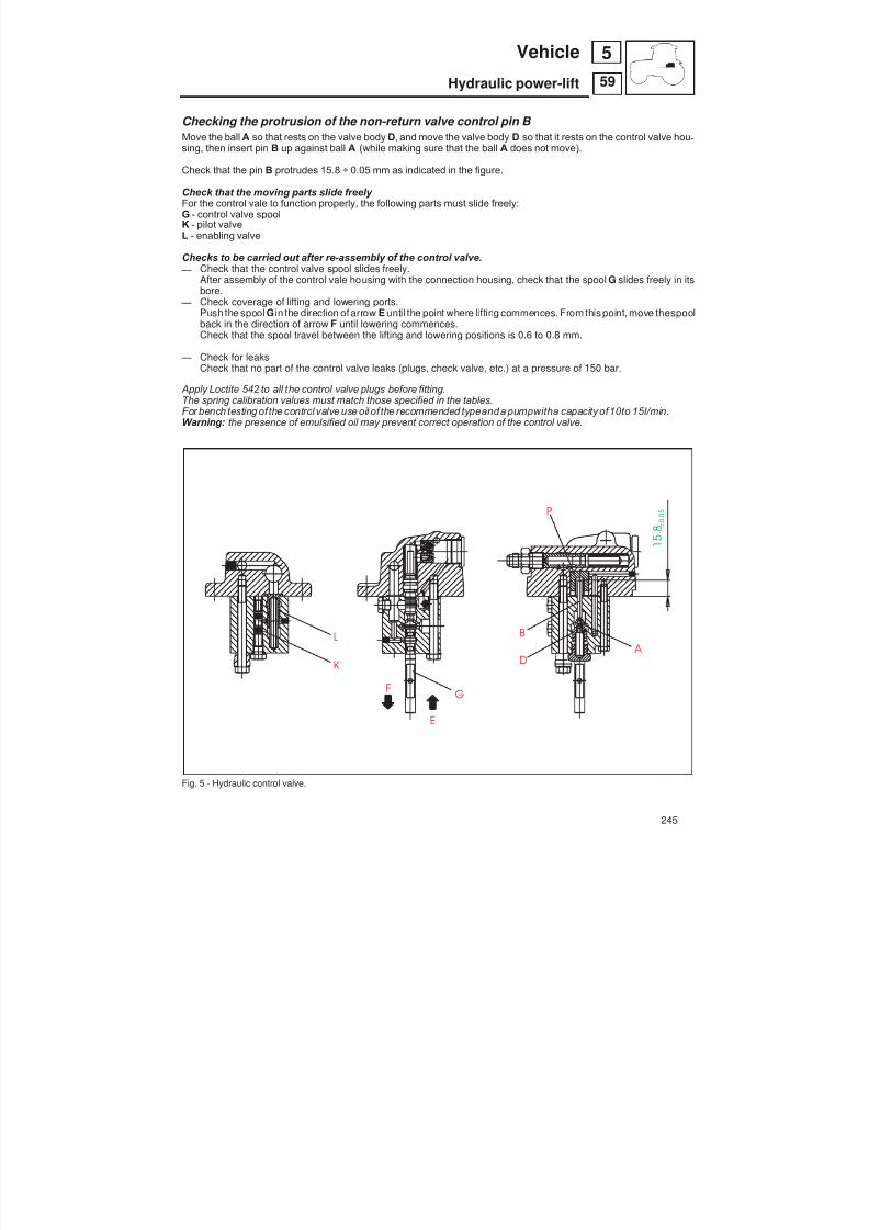
8/19/2019 Agrocompact f60 f70 f80 f90 Repair manual
http://slidepdf.com/reader/full/agrocompact-f60-f70-f80-f90-repair-manual 245/519
A
B
D
L
K
P
GF
E
1 5
. 8 ± 0
. 0 5
Checking the protrusion of the non-return valve control pin B Move the ball A so that rests on the valve body D, and move the valve body D so that it rests on the control valve hou -sing, then insert pin B up against ball A (while making sure that the ball A does not move).
Check that the pin B protrudes 15.8 ÷ 0.05 mm as indicated in the figure.
Check that the moving parts slide freely For the control vale to function properly, the following parts must slide freely:G - control valve spoolK - pilot valveL - enabling valve
Checks to be carried out after re-assembly of the control valve. — Check that the control valve spool slides freely.
After assembly of the control vale housing with the connection housing, check that the spool G slides freely in itsbore.
— Check coverage of lifting and lowering ports.Push the spool G in the direction of arrow E until the point where lifting commences. From this point, move thespoolback in the direction of arrow F until lowering commences.Check that the spool travel between the lifting and lowering positions is 0.6 to 0.8 mm.
— Check for leaksCheck that no part of the control valve leaks (plugs, check valve, etc.) at a pressure of 150 bar.
Apply Loctite 542 to all the control valve plugs before fitting.The spring calibration values must match those specified in the tables.For bench testing of the control valve use oil of the recommended typeanda pumpwitha capacity of10to 15l/min.Warning: the presence of emulsified oil may prevent correct operation of the control valve.
Fig. 5 - Hydraulic control valve.
245
59
5Vehicle
Hydraulic power-lift

8/19/2019 Agrocompact f60 f70 f80 f90 Repair manual
http://slidepdf.com/reader/full/agrocompact-f60-f70-f80-f90-repair-manual 246/519
Fig. 6 - Lift control adjustment diagram.F - Position control lever (yellow knob)G - Draft control lever (green knob)
246
59
5 Vehicle
Hydraulic power-lift - first version

8/19/2019 Agrocompact f60 f70 f80 f90 Repair manual
http://slidepdf.com/reader/full/agrocompact-f60-f70-f80-f90-repair-manual 247/519
Adjusting the lift (Fig. 6)
Warning: before adjustment, attach a weight of approx. 200 kg to the 3-point hitch.
Adjust the forks of the external tie-rods of the lift control linkage so that the yellow lever and the green lever are free tomove the entire length of the control slot.
Adjusting the lift travel - YELLOW LEVER -
Start the engine, and move the yellow lever to the maximum lift position and move the green lever to position 12 in itscontrol slot. Adjust screw E (fig. 6), so that it is up against its stop when the reference markson the right-hand side of the lift housingand the lift arm coincide.If necessary, also adjust fork B of tie-rod A .
Adjusting the GREEN LEVER
Move theyellowlever to theposition CONTR of its control slot, and check that when the green lever is moved from posi -tion 12 towards 0 , the lifting action commences when the lever is in correspondence with position 4.If not, adjust fork D of tie-rod C.
Checking operation of the safety stop.
Move the green lever to the maximum lift position (position 0 ). The lift arms will be raised, rotating through a further an -gle of approx. 4° (corresponding to a movement of the notch on the lift arm of 6 mm).
Checking balance.
With the yellow lever in the CONTR position, move thegreen lever from position 12 to 4 to find the point of balance (be-
fore the lifting actionbegins); check that when thecounterweight applied to the lift arms is pulledupwards, the lift raisesthe arms, and that when the counterweight is pushed downwards, the lift lowers the arms.
Adjusting the lift control levers
Screw the self-locking screws A - B fully home, unscrewscrews A one and a half turns and screws B a half turn.
Operate the levers to check the effort required.
If necessary, adjust the screws until the levers functioncorrectly.
Fig. 7 - Adjusting the lift control levers
247
59
5Vehicle
Hydraulic power-lift

8/19/2019 Agrocompact f60 f70 f80 f90 Repair manual
http://slidepdf.com/reader/full/agrocompact-f60-f70-f80-f90-repair-manual 248/519
Yellow = Oil delivery to the hydraulic control valveBlue = Oil flow from the control valve to the lowering valve
Green = Oil for piloting the valvesRed = Pressurised oil to the lift piston
Fig. 8 - Lift hydraulic circuit.
1 - Valvematic2 - Anti-shock valve3 - Down valve4 - Control valve5 - Pilot valve6 - Enabling valve7 - Inlet valveP - PumpT - Return
248
59
5 Vehicle
Hydraulic power-lift
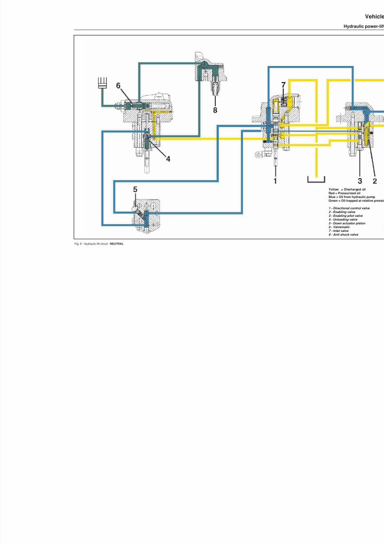
8/19/2019 Agrocompact f60 f70 f80 f90 Repair manual
http://slidepdf.com/reader/full/agrocompact-f60-f70-f80-f90-repair-manual 249/519
Fig. 9 - Hydraulic lift circuit - NEUTRAL
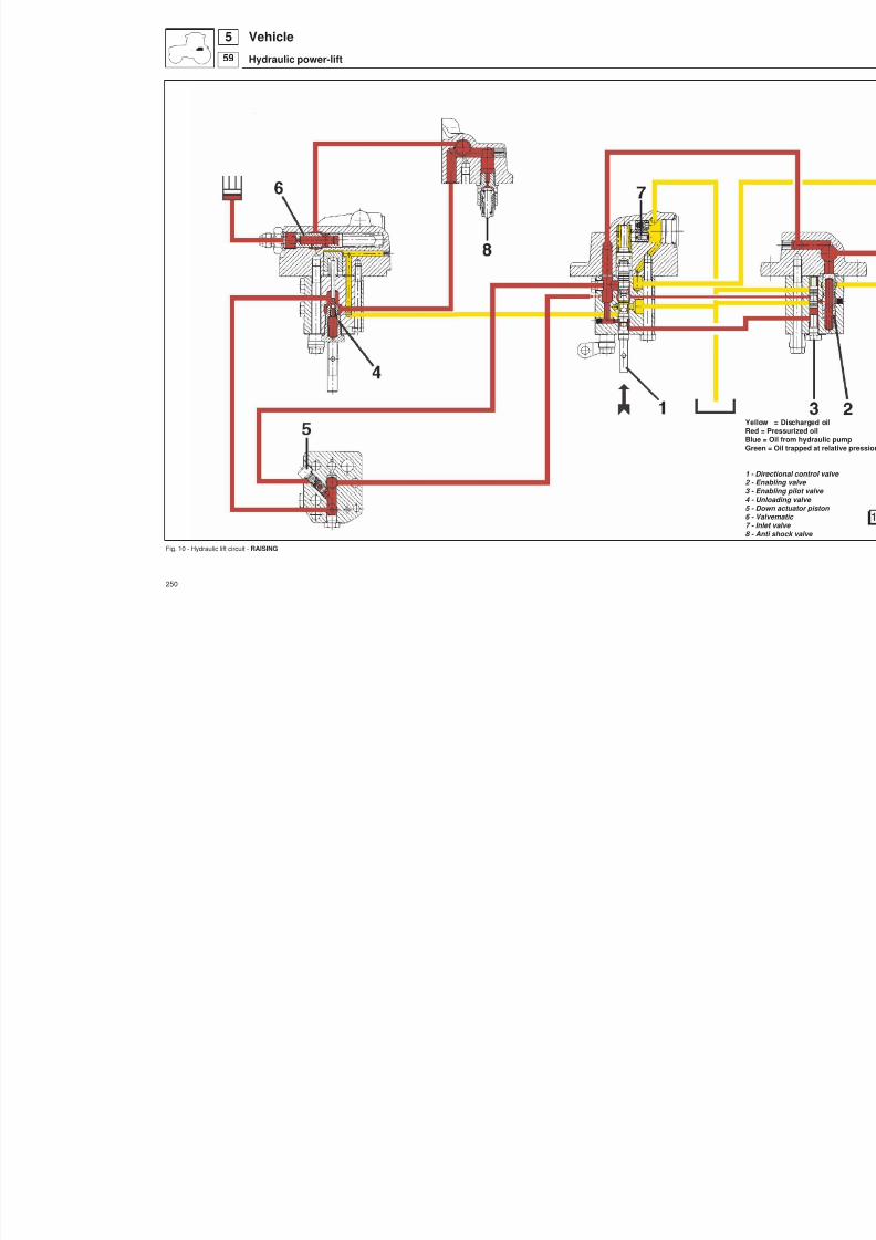
8/19/2019 Agrocompact f60 f70 f80 f90 Repair manual
http://slidepdf.com/reader/full/agrocompact-f60-f70-f80-f90-repair-manual 250/519
Fig. 10 - Hydraulic lift circuit - RAISING
250
Vehicle
Hydraulic power-lift
559
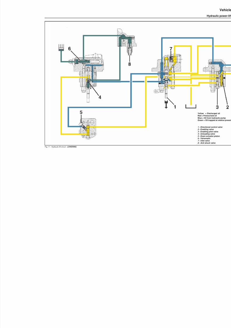
8/19/2019 Agrocompact f60 f70 f80 f90 Repair manual
http://slidepdf.com/reader/full/agrocompact-f60-f70-f80-f90-repair-manual 251/519
Fig. 11 - Hydraulic lift circuit - LOWERING

8/19/2019 Agrocompact f60 f70 f80 f90 Repair manual
http://slidepdf.com/reader/full/agrocompact-f60-f70-f80-f90-repair-manual 252/519
Fig. 12 - Control linkage for draft control.
Fig. 13 - Lift hydraulic control valve. Fig. 14 - Section views of the lift
252
Vehicle
Hydraulic power-lift
559

8/19/2019 Agrocompact f60 f70 f80 f90 Repair manual
http://slidepdf.com/reader/full/agrocompact-f60-f70-f80-f90-repair-manual 253/519
Fig. 15 - Pins of the draft control and position control levers
Fig. 16 - Control linkage for draft control and stop screw for the position control lever
253
59
5Vehicle
Hydraulic power-lift

8/19/2019 Agrocompact f60 f70 f80 f90 Repair manual
http://slidepdf.com/reader/full/agrocompact-f60-f70-f80-f90-repair-manual 254/519
Fig. 17 - Top view of the lift.
Fig. 18 - Rear view of the lift.
254
59
5 Vehicle
Hydraulic power-lift
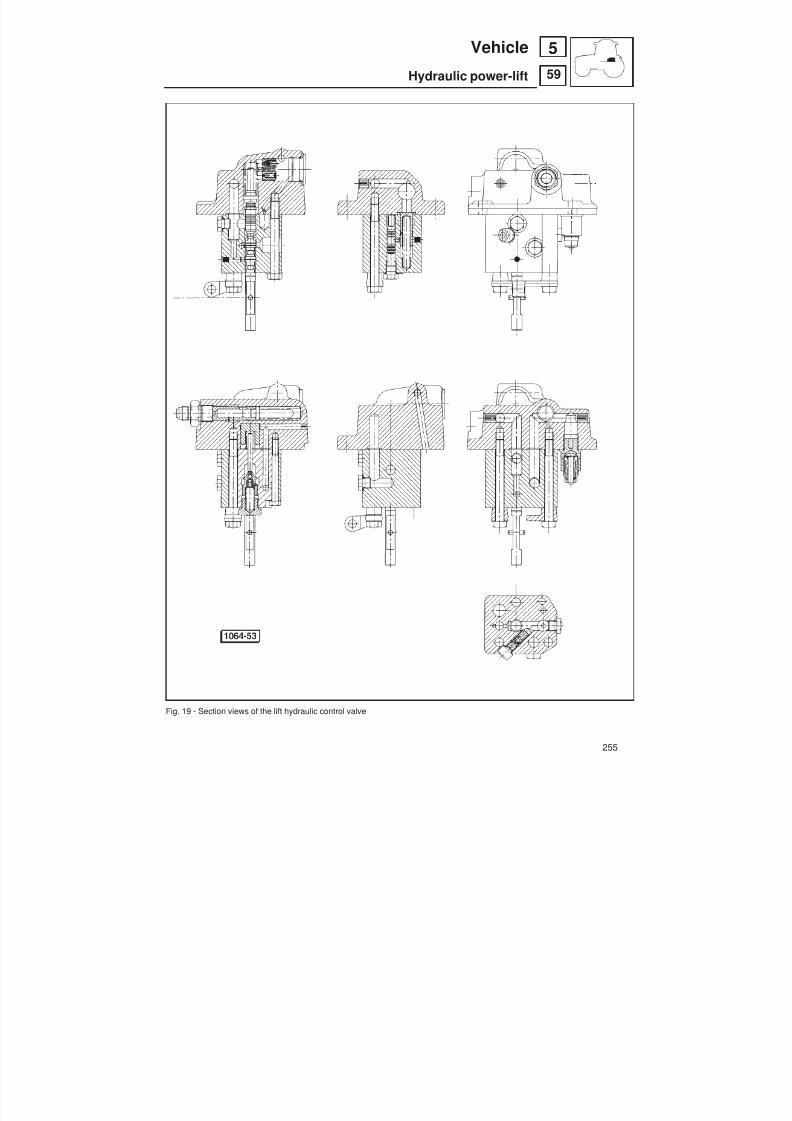
8/19/2019 Agrocompact f60 f70 f80 f90 Repair manual
http://slidepdf.com/reader/full/agrocompact-f60-f70-f80-f90-repair-manual 255/519
Fig. 19 - Section views of the lift hydraulic control valve
255
59
5Vehicle
Hydraulic power-lift
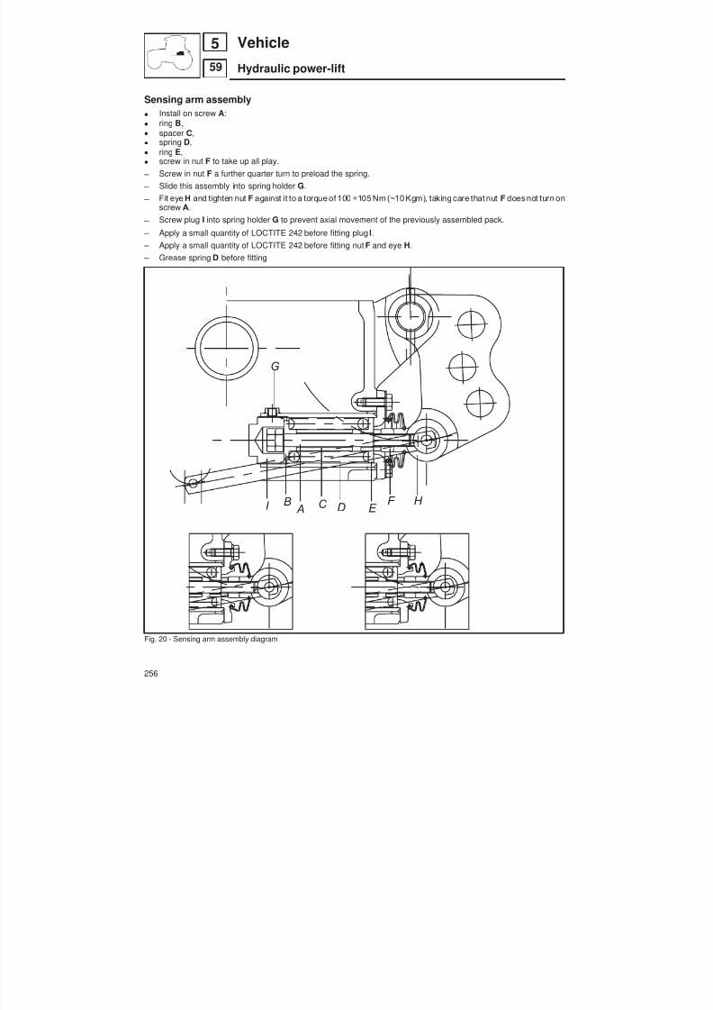
8/19/2019 Agrocompact f60 f70 f80 f90 Repair manual
http://slidepdf.com/reader/full/agrocompact-f60-f70-f80-f90-repair-manual 256/519
I B A C D E
F H
G
Sensing arm assembly Install on screw A : ring B , spacer C , spring D, ring E , screw in nut F to take up all play.
– Screw in nut F a further quarter turn to preload the spring.
– Slide this assembly into spring holder G .
– Fit eye H and tighten nut F against it to a torque of 100 ÷105 Nm (~10 Kgm), taking care that nut F does not turn onscrew A.
– Screw plug I into spring holder G to prevent axial movement of the previously assembled pack.
– Apply a small quantity of LOCTITE 242 before fitting plug I.
– Apply a small quantity of LOCTITE 242 before fitting nut F and eye H. – Grease spring D before fitting
Fig. 20 - Sensing arm assembly diagram
256
59
5 Vehicle
Hydraulic power-lift

8/19/2019 Agrocompact f60 f70 f80 f90 Repair manual
http://slidepdf.com/reader/full/agrocompact-f60-f70-f80-f90-repair-manual 257/519
Power-lift distributor valve spring setting specifications
oil flow control valve springno. of springs used n. 1wire diameter mm 1,4external diameter mm 7,8released spring mm 54loaded spring (N 40,4) -kg 4,115 mm 47,5
(N 66) - kg 6,727 mm 43,37
pilot valve spring
no. of springs used n. 1wire diameter mm 0,9external diameter mm 7,8released spring mm 25,5loaded spring (N 21) - kg 2,133 mm 15,2
(N 28,5) - kg 2,899 mm 11,5
hydraulic distributor springno. of springs used n. 1wire diameter mm 1,2external diameter mm 10,4released spring mm 110
loaded spring (N 43) - kg 4,4 mm 65(N 39) - kg 4 mm 60
nonreturn valve springno. of springs used n. 2wire diameter mm 1,1external diameter mm 8,8released spring mm 25loaded spring (N 29) - kg 2,96 mm 17
(N 43) - kg 4,43 mm 13
valvematicspringno. of springs used Nº 1wire diameter mm 1,2external diameter mm 9,5released spring mm 57,3loaded spring (N 41,3) - kg 4,2 mm 35
(N 54,3) - kg 5,5 mm 25,8
257
59
5Vehicle
Hydraulic power-lift

8/19/2019 Agrocompact f60 f70 f80 f90 Repair manual
http://slidepdf.com/reader/full/agrocompact-f60-f70-f80-f90-repair-manual 258/519
ELECTRONIC LIFTThe electronic lift is controlled by an electronic control unit and a control panel.
The electronic control unit processes the signals from the input devices and generates the output signals for the elec -tro-hydraulic control of the lift control valve.
The system provides Draft and Position control functions.
IMPORTANTThe "ALLROUND TESTER" provides the interface for electronic control unit self-diagnostic and programming operations. All the display messagesaregiven in thechapter "LIFT TESTER Control unit version 1.24A" of the Appendix (see table of contents).
Fig. 1 - Configuration of the electronic lift system1 - Control panel2 - Electro-hydraulically operated control valve (2 proportional solenoid valves)3 - Hydraulic pump4 - Draft sensor5 - Position sensor6 - Maximum lift height control knob7 - Lowering speed control knob8 - Draft/wheelslip intermix control knob9 - Depth control knob10 - Up/Down control11 - Lock and alarm warning light12 - Manual UP control13 - Manual DOWN control
258
59
5 Vehicle
Electronic power-lift
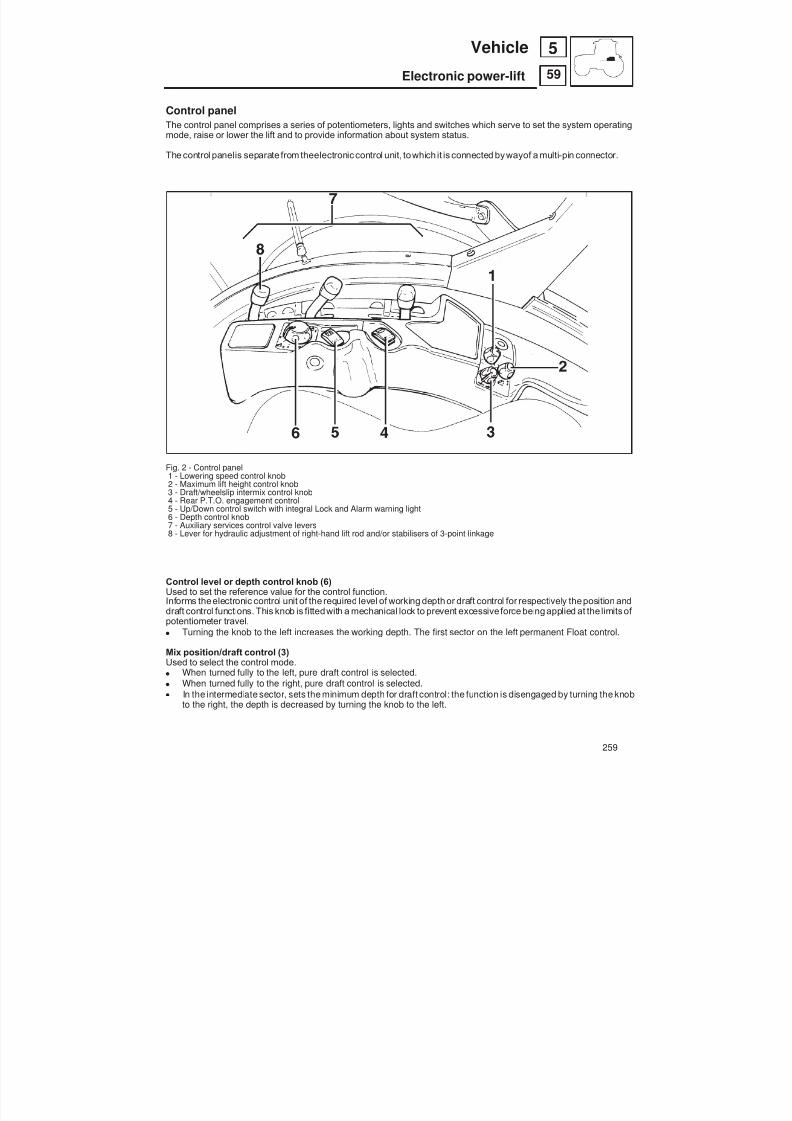
8/19/2019 Agrocompact f60 f70 f80 f90 Repair manual
http://slidepdf.com/reader/full/agrocompact-f60-f70-f80-f90-repair-manual 259/519
Control panelThe control panel comprises a series of potentiometers, lights and switches which serve to set the system operating
mode, raise or lower the lift and to provide information about system status.
The control panelis separate from theelectronic control unit, towhich it is connected by wayof a multi-pin connector.
Fig. 2 - Control panel1 - Lowering speed control knob2 - Maximum lift height control knob3 - Draft/wheelslip intermix control knob4 - Rear P.T.O. engagement control5 - Up/Down control switch with integral Lock and Alarm warning light6 - Depth control knob7 - Auxiliary services control valve levers8 - Lever for hydraulic adjustment of right-hand lift rod and/or stabilisers of 3-point linkage
Control level or depth control knob (6)Used to set the reference value for the control function.Informs theelectronic control unit of the required level of working depth or draft control for respectively theposition anddraft control functions. This knob is fittedwith a mechanical lock to prevent excessive force being applied at the limits of potentiometer travel.
Turning the knob to the left increases the working depth. The first sector on the left permanent Float control.
Mix position/draft control (3)Used to select the control mode.
When turned fully to the left, pure draft control is selected. When turned fully to the right, pure draft control is selected. In the intermediate sector, sets the minimum depth for draft control: the function is disengaged by turning the knob
to the right, the depth is decreased by turning the knob to the left.
259
59
5Vehicle
Electronic power-lift
8/19/2019 Agrocompact f60 f70 f80 f90 Repair manual
http://slidepdf.com/reader/full/agrocompact-f60-f70-f80-f90-repair-manual 260/519
Lowering speed control knob (1)Used to vary the rate at which the linkage is lowered.Sets the maximum aperture of the proportional solenoid valve that controls the lowering speed.Turning the knob to the left reduces the lowering speed.
Maximum lift height control knob (2)Used to set the maximum height to which the linkage is raised when the driver operates the lift control.Turning the knob to the left reduces the maximum lift height.
Up/Down control switch (5)Rocker switch used to raise or lower the linkage, incorporating a safety lockout/release.
Up controlPressing this button for at least 0.2 seconds raises the lift to the maximum lift height.
Control/Float modeIf the Down button is pressed for less than 0.2 seconds, Control mode is activated.If the button is held pressed for longer, Float mode is activated. In the latter case, the implement will be lowered at therate set by the lowering speed control knob and the lowering solenoid valve will be operated for as long as the button isheld pressed.The moment the button is released, the system will exit Float mode and automatically resume Control mode.
Lock/release Activates/deactivates total lock out of the control panel. When the lock is activated, the warning light illuminates.On starting, the system is always locked; to release the lock, hold the Up control button pressed for 3 seconds until thelight goes out. The light will flash rapidly while the button is pressed.To activate the lock, hold theUp control buttonpressed for 3 seconds after which the light will illuminate; again, the lightwill flash rapidly while the button is being pressed.On activating the lock, the linkage is immediately raised to the height determined by the maximum lift height controlknob. Any subsequent alteration to the position of the lift controls (including the maximum lift height control knob) willhave no effect on the position of the linkage until the lock is released.
Lift status indicator lightThis light provides information about the operating status of the lift.If the light is permanently illuminated, this indicates that the system is locked.If the light is off, this indicates that the system is operating normally.If the light is flashing, this indicates an alarm condition.
WARNING: only use the Up control button located on the solenoid valve of the lift control valve in cases of extreme ne -cessity and when the engine is running at idle speed. Release the button before the linkage reaches the maximum he -ight, as the automatic stop determined by the both position sensor and the safety switch is excluded during this opera -tion.
260
59
5 Vehicle
Electronic power-lift

8/19/2019 Agrocompact f60 f70 f80 f90 Repair manual
http://slidepdf.com/reader/full/agrocompact-f60-f70-f80-f90-repair-manual 261/519
Remote pushbuttons for lift operation from ground
Two remote pushbuttons are located on the rear fender.
To enable these pushbuttons it is first necessary to release the lift control system.
Operation of themanual controls overrides any current lift functions and places thecontrol unit in STOP condition, awai -ting new control signals.
Fig. 3 - Lift control pushbuttons A - Up B - Down
Fig. 4 - Flow control valve used to regulate the rate of oil flow to the lift cylinder. Fig. 5 - Ground-operated lift controls.
261
59
5Vehicle
Electronic power-lift

8/19/2019 Agrocompact f60 f70 f80 f90 Repair manual
http://slidepdf.com/reader/full/agrocompact-f60-f70-f80-f90-repair-manual 262/519
Lift operationOn starting the engine, the lift is in Lock condition; to release the lift, press the UP switch for at least 3 seconds.The lift control system enters STOP status in which condition the lift may be raised to the maximum lift height by pres -sing the switch for at least 0.5 seconds but no more than 3 seconds.To activate the lift control system, press the DOWNswitch for less than0.3 seconds; if the switch is heldpressed for lon -ger, FLOAT mode is activated and CONTROL mode will only be resumed when the switch is released.The functions of the three potentiometers are as follows:1 - MAXIMUM LIFT HEIGHT (used to set the maximum height to which the linkage can be raised)2 - LOWERING SPEED (used to set the rate at which the implement is lowered).3 - CONTROL (used to select the control type: when turned fully to the left POSITION control is selected, when turned fully right DRAFT control is selected).When turned to the intermediate sector, mixed draft and position control is selected.
LIFT ALARMS
CODE MESSAGE ON TESTER Alarm description
11 UPSV DISCONN. UP SOLENOID DISCONNECTED
12 UPSV S.C. UP SOLENOID SHORT CIRCUIT
13 DWSV DISCONN. DOWN SOLENOID DISCONNECTED
14 DWSV S.C. DOWN SOLENOID SHORT-CIRCUIT
15 - -
21 POS.SENS.S.C. POSITION SENSOR SHORT CIRCUIT
22 POS.SENS. DIS. POSITION SENSOR DISCONNECTED
23 GEN.FAIL.CPU GENERAL FAILURE OF CPU.
24 -
25 -
31 -
41 DRAFT SENS. DIS. DRAFT SENSOR DISCONNECTED
42 DRAFT SENS. S.C. DRAFT SENSOR SHORT CIRCUIT
45 EEPROM CHECK EEPROM ERROR
Example display of code 23:
all times in secondson
2 0.3 0.3 0.3 1,2 0.2 0.2 0.2 0.2 0.2 2off
The criteria for encoding are as follows: — light off for 2 seconds
— number of 0.3 second flashes corresponding to the tens digit — light off continuously for 1.2 seconds — number of 0.2 second flashes corresponding to the units digit — repetition of the cycle until the alarm ceases
262
59
5 Vehicle
Electronic power-lift
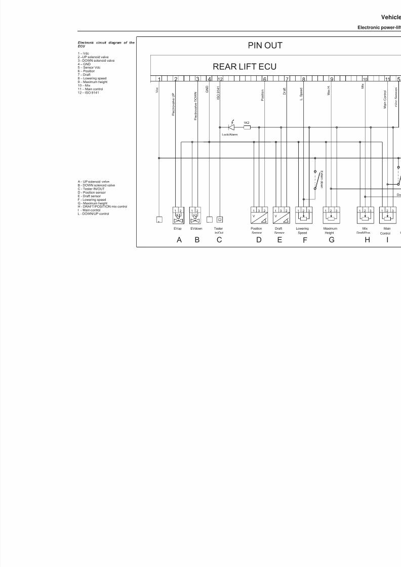
8/19/2019 Agrocompact f60 f70 f80 f90 Repair manual
http://slidepdf.com/reader/full/agrocompact-f60-f70-f80-f90-repair-manual 263/519
Electronic circuit diagram of theECU
1 – Vdc2 –UP solenoid valve3 - DOWN solenoid valve4 – GND
5 – Sensor Vdc6 – Position7 – Draft8 – Lowering speed9 – Maximum height10 – Mix11 – Main control12 – ISO 9141
A - UP solenoid valveB - DOWN solenoid valveC - Tester IN/OUTD - Position sensor E - Draft sensor F - Lowering speedG - Maximum heightH - DRAFT/POSITION mix controlI - Main controlL - DOWN/UP control
REAR LIFT ECU
1 2
EVup
1 2 6
E l e c t r o v a l v e
U P
P o s i t i o n G
N D
3 7
Sensor Position
31
V
2
V c c
2
EVdown
1
E l e c t r o v a l v e
D O W N
Sensor Draft
2
V
1 3
D r a f t
SpeedLowering
21 3
L . S p e e d
MaximumHeight
1 2 3
M a x
H .
8 9
+ -
4 12
I S O 9 1 4 1
Lock/Alarm
1K2
Tester In/Out
E x t er n d own
PIN OUT
A B C D E F G
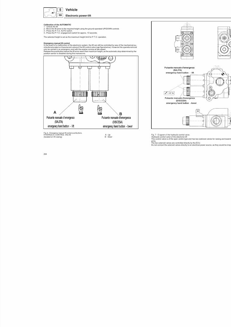
8/19/2019 Agrocompact f60 f70 f80 f90 Repair manual
http://slidepdf.com/reader/full/agrocompact-f60-f70-f80-f90-repair-manual 264/519
Calibration of the AUTOMATIC1 - Unlock the lift.2 - Move the lift arms to the required height using the ground-operated UP/DOWN controls.3 - Press the P.T.O. AUTO switch.4 - Press the P.T.O. engagement switch for approx. 10 seconds.
The selected height is set as the maximum height limit for P.T.O. operation.
Emergency manual lift controlIn the event of a malfunction of the electronic system, the lift can still be controlled by way of the mechanical pu -shbuttonslocated on thesolenoid valvesof the lift control valve (see figurebelow). However this operationshouldonly be carried in an emergency and with the engine running at idle speed.Release the pushbutton before the lift arms reach their maximum height, as the automatic stop determined by theposition sensor is disabled during this manoeuvre.
Fig. 6 - Emergency manual lift control pushbuttons.HYDRAULIC CONTROL VALVE A - Up Fig. 7 - Diagram of the hydraulic control valve.(located on lift casing) B - Down Hydraulic control valve of the electronic lift
This control valve is of the open centre type and has two soarms.The two solenoid valves are controlled directly by the ECU.Do not connect the solenoid valves directly to an electrical p
264
Vehicle
Electronic power-lift
559
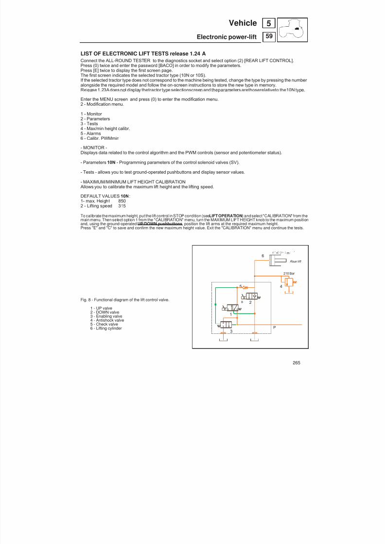
8/19/2019 Agrocompact f60 f70 f80 f90 Repair manual
http://slidepdf.com/reader/full/agrocompact-f60-f70-f80-f90-repair-manual 265/519
LIST OF ELECTRONIC LIFT TESTS release 1.24 AConnect the ALL-ROUND TESTER to the diagnostics socket and select option (2) [REAR LIFT CONTROL].
Press (0) twice and enter the password [BACO] in order to modify the parameters.Press [E] twice to display the first screen page.The first screen indicates the selected tractor type (10N or 10S).If the selected tractor type does not correspond to the machine being tested, change the type by pressing the number alongside the required model and follow the on-screen instructions to store the new type in memory.Release1.23Adoes not display thetractor type selectionscreen and theparameters arethoserelativeto the10N type.
Enter the MENU screen and press (0) to enter the modification menu.2 - Modification menu.
1 - Monitor 2 - Parameters3 - Tests4 - Max/min height calibr.5 - Alarms6 - Calibr. PWMmin
- MONITOR -Displays data related to the control algorithm and the PWM controls (sensor and potentiometer status).
- Parameters 10N - Programming parameters of the control solenoid valves (SV).
- Tests - allows you to test ground-operated pushbuttons and display sensor values.
- MAXIMUM/MINIMUM LIFT HEIGHT CALIBRATION Allows you to calibrate the maximum lift height and the lifting speed.
DEFAULT VALUES 10N :1- max. Height 8502 - Lifting speed 315
To calibrate themaximum height, put the lift control in STOP condition (see LIFTOPERATION ) andselect "CALIBRATION" from themain menu. Then select option 1 from the "CALIBRATION" menu, turn the MAXIMUM LIFT HEIGHT knob to the maximum positionand, using the ground-operated UP/DOWN pushbuttons , position the lift arms at the required maximum height.Press "E" and "C" to save and confirm the new maximum height value. Exit the "CALIBRATION" menu and continue the tests.
Fig. 8 - Functional diagram of the lift control valve.
1 - UP valve2 - DOWN valve3 - Enabling valve4 - Antishock valve5 - Check valve
6 - Lifting cylinder
265
59
5Vehicle
Electronic power-lift
Rear lift
210 Bar
= . m
P
B
1
2
3
45
6

8/19/2019 Agrocompact f60 f70 f80 f90 Repair manual
http://slidepdf.com/reader/full/agrocompact-f60-f70-f80-f90-repair-manual 266/519
Fig. 9 - Control valve hydraulic circuit - NEUTRAL
1 - UP solenoid valve2 - DOWN solenoid valve3 - Enabling valve4 - Check valveP - Oil flow
266
59
5 Vehicle
Electronic power-lift

8/19/2019 Agrocompact f60 f70 f80 f90 Repair manual
http://slidepdf.com/reader/full/agrocompact-f60-f70-f80-f90-repair-manual 267/519
Fig. 10 - Control valve hydraulic circuit - LIFTING
1 - UP solenoid valve2 - DOWN solenoid valve3 - Enabling valve4 - Check valveP - Oil flow
267
59
5Vehicle
Electronic power-lift

8/19/2019 Agrocompact f60 f70 f80 f90 Repair manual
http://slidepdf.com/reader/full/agrocompact-f60-f70-f80-f90-repair-manual 268/519
Fig. 11 - Control valve hydraulic circuit - LOWERING
1 - UP solenoid valve2 - DOWN solenoid valve3 - Enabling valve4 - Check valveP - Oil flow
268
59
5 Vehicle
Electronic power-lift

8/19/2019 Agrocompact f60 f70 f80 f90 Repair manual
http://slidepdf.com/reader/full/agrocompact-f60-f70-f80-f90-repair-manual 269/519
Fig. 12 - Hydraulic control valve for electronic lift.
269
59
5Vehicle
Electronic power-lift

8/19/2019 Agrocompact f60 f70 f80 f90 Repair manual
http://slidepdf.com/reader/full/agrocompact-f60-f70-f80-f90-repair-manual 270/519
Fig. 13 - Position sensor calibration of the electronic lift.
POSITION SENSOR CALIBRATION.If a new position sensor is fitted, it will have to be adjusted. Proceed as follows:1 – Move the lift arms to the minimum height position, connect the "ALL AROUND TESTER" and access the maximum
height calibration screen; screw the sensor in or out until a number between 4 and 10 is displayed.2 – Tighten down the sensor 3 – Proceed with the calibration of the maximum height.
270
59
5 Vehicle
Electronic power-lift

8/19/2019 Agrocompact f60 f70 f80 f90 Repair manual
http://slidepdf.com/reader/full/agrocompact-f60-f70-f80-f90-repair-manual 271/519
Fig. 14 - Pin for draft control of the electronic lift1 - Pressure test fitting for lift cylinder pressure2 - Anti-shock valve3 - Lift control valve
271
59
5Vehicle
Electronic power-lift
1
2
3

8/19/2019 Agrocompact f60 f70 f80 f90 Repair manual
http://slidepdf.com/reader/full/agrocompact-f60-f70-f80-f90-repair-manual 272/519
Fig. 15 - Rear view of the electronic lift.
272
59
5 Vehicle
Electronic power-lift
A
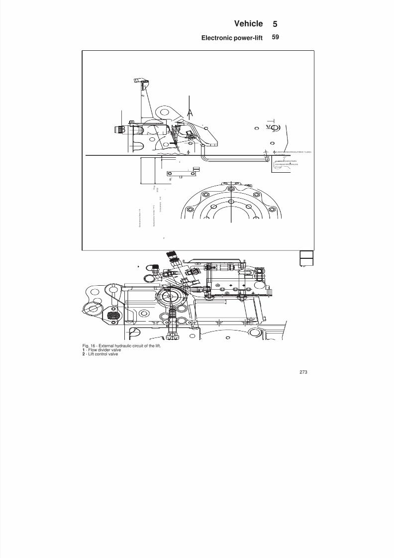
8/19/2019 Agrocompact f60 f70 f80 f90 Repair manual
http://slidepdf.com/reader/full/agrocompact-f60-f70-f80-f90-repair-manual 273/519
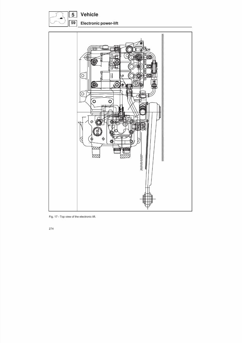
8/19/2019 Agrocompact f60 f70 f80 f90 Repair manual
http://slidepdf.com/reader/full/agrocompact-f60-f70-f80-f90-repair-manual 274/519
Fig. 17 - Top view of the electronic lift.
274
59
5 Vehicle
Electronic power-lift
K I C K - O UT
F L OA T
DE T E NT .
P A
T .
E
L E S
A
( S a
l i t a )
( d i s c e s a
)
A s s e t u b o a l i m
. d
a r e g o l a t o r e
d i
f l u s s o
x s o l l e v .
m e c c a n i c o

8/19/2019 Agrocompact f60 f70 f80 f90 Repair manual
http://slidepdf.com/reader/full/agrocompact-f60-f70-f80-f90-repair-manual 275/519
Precautions for electronic equipmentThe tractor is equipped with a number of sensitiveelectrical devices andelectronic components. In particular, electronic
components do not tolerate polarity inversion, over-current, connection errors, etc..The electronic components areprovided with internal and external protections,but thefollowingprecautions arestill ne -cessary:
— Switch off the control panel before carrying out any work on electrical components. — Do notuse a screwdriver of lightbulb to test for electrical current; only use the appropriate diagnostic equipment (te -
ster). — Do not apply excessive force when connecting and disconnecting electrical connectors; do not prise connectors
apart using a screwdriver, and always respect the polarity of the connection. — In the event of a fault in a circuit controlled by an electronic control unit, do not immediately replace the control unit,
but first check that the sensors and actuators are functioning correctly. — When replacing a defective electronic control unit, only unscrew the retaining screws; avoid interfering with other
screws as these could be calibration screws. — Inspect contacts on sensors and connectors for corrosion. — Do not use arc welding in the vicinity of electrical circuits. — Avoid short-circuits and polarity inversion. — When working on components controlled by microprocessors, always disconnect the power supply by turning the
ignition key to the STOP position before disconnecting the component. — If the tractor is to be resprayed and passed through a paint baking oven, remove all electronic components. — Do not insert the probes of the tester into multi-pole sockets on connectors or other devices (this deforms the con -
tacts and thus leads to poor connections). — Do not test for thepresence of electrical currentby causing a spark, i.e. by short-circuitingcomponentsacrosswires
or to earth. — Do not reverse the polarity or swap over wires in multi-pole connectors.
CHECKING THE ELECTRONIC SYSTEM
Elements to check: — Sensors — Electronic control units — Actuators
1) Checking the system power supply: — current present at input to the connector plugged into the device; — current present at output from connector — earth connection — voltage correct.2) Check downstream components: sensors .3) Check upstream components.
CHECKING MECHANICAL COMPONENTSCheck thesplines on theexternal and internal lift arms fordamageor excessivewear; replace thelevers if necessary.
Check the bushes of the lift arm shaft for scoring or excessive wear.Check the bushes and the pins connecting the lift arms to the hydraulic cylinder are not worn and are firmly inserted inthe seats on the levers.
Check the diameters of the rod and bushes in the cylinders and compare with the maximum wear limits in the table.
Check that the splines on the lifting shaft are not excessively worn and that the machines surfaces in contact with thesupport bushes are not damaged.
NOTE: whenever the lifting cylinders are dismantled, new seals must be fitted.
275
59
5Vehicle
Electronic power-lift

8/19/2019 Agrocompact f60 f70 f80 f90 Repair manual
http://slidepdf.com/reader/full/agrocompact-f60-f70-f80-f90-repair-manual 276/519
Front hydraulic liftOn request the tractor can be equipped with the front hydraulic lifting system.
It is operated by means of two hydraulic cylinders actuated by the related control lever placed at the right-hand side of the operator driving position.The lever controls a single-acting distributor valve linked to the rear tractor power-lift case.
InspectionsEnsure that the cylinder pin bushings are not worn and be sure these are firmly secured in their seats.NOTE: Replace gaskets after each hydraulic lifting cylinder disassembly.
Specificationspower-lift type with two hydraulic cylinders and removable armshydraulic cylinder type single-actingoil supply from the rear auxiliary
hydraulic distributorpeak operating pressure bar 180cylinder stem diameter mm 50lifting stroke mm 170distance between both lower link ends mm 865lifting capacity kg 1500
A - Front lift cylinders (2)
B - Hydraulic accumulator Volume 0.700 litresNitrogen precharge 130 bar maximum operating pressure 250 ba r
C - Antishock valve
D - Lowering speed regulator valve
E - Lockout cock (prevents oil fromdischarging from the cylinders whentransporting raised implements on the road).
Fig. 1 - Lift operation.
276
59
5 Vehicle
Front hydraulic power-lift

8/19/2019 Agrocompact f60 f70 f80 f90 Repair manual
http://slidepdf.com/reader/full/agrocompact-f60-f70-f80-f90-repair-manual 277/519
Hydraulic accumulator and antishock valve for front lift
The front lift is equipped with a hydraulic accumulator with an antishock valve. This improves hydraulic system perfor -mance and reduces strain on the front axle.
Fig. 2 - Front lift components.
277
59
5Vehicle
Front hydraulic power-lift

8/19/2019 Agrocompact f60 f70 f80 f90 Repair manual
http://slidepdf.com/reader/full/agrocompact-f60-f70-f80-f90-repair-manual 278/519
A - TO LIFT CYLINDERSB - RATE OF DROP VALVEC - ANTI-SHOCK VALVED - ACCUMULATORE - LOWERING SPEED
CONTROL VALVEF - DIRECTIONAL CONTROL VALVE
Fig. 3 - Oil pressure accumulator and anti-shock valve. (The directional valve to which is connecting, is convertable into sin -gle-acting. For the operations to see auxiliary systems chapter).
278
59
5 Vehicle
Front hydraulic power-lift

8/19/2019 Agrocompact f60 f70 f80 f90 Repair manual
http://slidepdf.com/reader/full/agrocompact-f60-f70-f80-f90-repair-manual 279/519
Front power take-offGeneral information
The power take-off clutch is a multidisk, oil-bath and electro-hydraulic control type.The front power take-off is directly linked to the crankshaft by means of a flexing coupling; while the shaft-end is equip -ped by an universal joint.
The oil used for P.T.O. operation is contained in the P.T.O. Casing.
A specific gear pump installed on the P.T.O. shaft sucks the oil, which flows first through a filter for being subsequentlyrouted under pressure to the clutch assembly through an electro-hydraulic distributor.
To avoid exceeding these values, we recommend that a suitable coupling is installed between the implement and thepower take-off.
The P.T.O. shaft rear teminal has clockwise direction of rotation (with respect to the driving position).
The electro-hydraulic control operates the system by way of a solenoid valve. When the valve is open, pressurised oilacts on the pistons to force together the driving plates and driven plates of the clutch and thereby transmit drive to theoutput shaft.
The P.T.O. clutch brake is operated mechanically by the piston during the return stroke determined by the helicalspring. Three pins attached to the piston push against the brake pressure plate.Control is electro-hydraulic type and isprovided by the relevant switching knob.
specificationspower take-off clutch
Clutch wet multi-plate with axial piston
number of plates 5
diameter of plates 105thickness of clutch plate packMinimum mm 27.32Maximum mm 29.90
N°of thrust plates 5
plate lubrication pressure bar 5
maximum engagement pressure setting bar 16 02+
P.T.O. pressure control valve bar 16 02+
Restrictor orifice mm 1.1
clutch spring specifications
Piston return spring
wire diameter mm 6
outside diameter mm 52,5
free length mm 50
length under compression kg 82 (808 Nm) mm 28kg 98 (978 Nm) mm 23,4
279
59
5Vehicle
Front power take-off
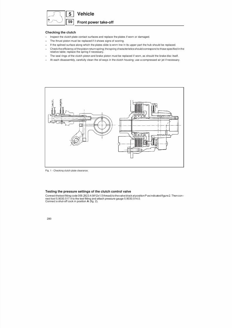
8/19/2019 Agrocompact f60 f70 f80 f90 Repair manual
http://slidepdf.com/reader/full/agrocompact-f60-f70-f80-f90-repair-manual 280/519
Checking the clutch – Inspect the clutch plate contact surfaces and replace the plates if worn or damaged. – The thrust piston must be replaced if it shows signs of scoring. – If the splined surface along which the plates slide is worn low in its upper part the hub should be replaced. – Check the efficiency of the piston return spring; the spring characteristics should correspondto those specified in the
relative table; replace the spring if necessary. – The seal rings of the clutch piston and brake piston must be replaced if worn, as should the brake disc itself. – At each disassembly, carefully clean the oil ways in the clutch housing; use a compressed air jet if necessary.
Fig. 1 - Checking clutch plate clearance.
Testing the pressure settings of the clutch control valveConnect thetest fitting code 009.2923.4 (M12x1.5 thread) to thevalve block at position P as indicatedfigure2. Then con -
nect tool 5.9030.517.4 to the test fitting and attach pressure gauge 5.9030.514.0.Connect a shut-off cock in position A (fig. 2).
280
59
5 Vehicle
Front power take-off

8/19/2019 Agrocompact f60 f70 f80 f90 Repair manual
http://slidepdf.com/reader/full/agrocompact-f60-f70-f80-f90-repair-manual 281/519
Allow the oil to flow through the valve block, take the following pressure readings:
SOLENOID EV.4 NOT ENERGISED SOLENOID EV.4 ENERGISEDSHUT-OFF VALVE OPEN SHUT-OFF VALVE CLOSED
Pressure control valve 2 Pressure limiting valve 3
Pump capacity l/min Pressure M bar Pump capacity l/min Pressure M bar
7 5 max. 7 15 min. 18 max.
1 - Filter (filtering capacity 25)
2 - Pressure control valve.3 - Pressure limiting valve4 - Solenoid valve ON / OFF
Fig. 2 - Testing the operating pressure in the P.T.O. clutch supply circuit.
281
59
5Vehicle
Front power take-off

8/19/2019 Agrocompact f60 f70 f80 f90 Repair manual
http://slidepdf.com/reader/full/agrocompact-f60-f70-f80-f90-repair-manual 282/519
Lubrication pipe Remove pipe and fit shut-off valve
Restrictor
to P.T.O. clutch
Return
pump delivery
suction
Fig. 3 - Hydraulic control and power system components.
282
59
5 Vehicle
Front power take-off

8/19/2019 Agrocompact f60 f70 f80 f90 Repair manual
http://slidepdf.com/reader/full/agrocompact-f60-f70-f80-f90-repair-manual 283/519
Instructions for disengaging the drive to the front P.T.O.
When front P.T.O.is not to beused for long periods, it is recommended that thedrive to theoutput shaft is disengaged.
Proceed as follows:Remove cover E , then remove spacer B (fig. 4) and place in the bottom of cover E in position D, as indicated in the dia -gram on the right-hand side of figure 2 (drive shaft disconnected). Now pull the shaft F forward to disengage it from thedrive coupling and position washer A in the groove G.Replace cover E .
To re-connect the front P.T.O. drive, remove cover E and washer A and push the drive shaft in. Replace washer A asshown in the diagram on the left of the figure (drive shaft connected), then replace cover E .
Fig. 4 - Drive shaft connected - Drive shaft disconnected
283
59
5Vehicle
Front power take-off

8/19/2019 Agrocompact f60 f70 f80 f90 Repair manual
http://slidepdf.com/reader/full/agrocompact-f60-f70-f80-f90-repair-manual 284/519
Fitting the "RING-FEEDER" rings - fig. 5Fit the parts in the order shown in the figure.
Tighten down the pulley hub on the crankshaft applying a torque of 34 ± 1.5 kgm (333 ± 15 Nm).
Fitting the oil seal on the front P.T.O. shaft - fig. 6To avoid damaging the seal during installation, first fit a protective sleeve A over the splines of the shaft as shown in fi -gure 6.
Fig. 5 - “RING-FEEDER” rings installed" Fig. 6 - Front P.T.O. assembly parts.
Fig. 7 Solenoid control valve block. Fig. 8 - P.T.O. output shaft.1 - Filter2 - Pressure limiting valve3 - Pressure control valve4 - Solenoid control valve
284
59
5 Vehicle
Front power take-off
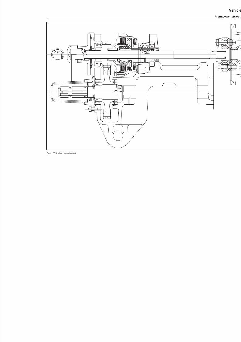
8/19/2019 Agrocompact f60 f70 f80 f90 Repair manual
http://slidepdf.com/reader/full/agrocompact-f60-f70-f80-f90-repair-manual 285/519
Fig. 9 - P.T.O. clutch hydraulic circuit.
Z 50
Z 22

8/19/2019 Agrocompact f60 f70 f80 f90 Repair manual
http://slidepdf.com/reader/full/agrocompact-f60-f70-f80-f90-repair-manual 286/519
Fig.10 - P.T.O. clutch hydraulic circuit
286
Vehicle
Front power take-off
559
l u b r i f .
m a n d a t a
8 5
°
M42x1.5

8/19/2019 Agrocompact f60 f70 f80 f90 Repair manual
http://slidepdf.com/reader/full/agrocompact-f60-f70-f80-f90-repair-manual 287/519
Fig. 11 - Servicing the front P.T.O. unit
A - Oil filler plug.
B - P.T.O. oil delivery line filter (to access for servicing, unscrew the two screws and remove the filter flange).
C - Oil level inspection window.To access, remove the plastic plug located on the left0-hand side of the front carrier.
D - Oil drain plug.
E - Wire mesh filter on suction line (clean the filter if you notice any control malfunction; then, if necessary, also clean or renew the de -livery line filter B ).
287
59
5Vehicle
Front power take-off
8/19/2019 Agrocompact f60 f70 f80 f90 Repair manual
http://slidepdf.com/reader/full/agrocompact-f60-f70-f80-f90-repair-manual 288/519
Diagnosing malfuntions
clutch slipping
P.T.O. brake does notapply
Verify activation of
the solenoid valve
check piston for free stroke
verify movement of piston
inspect clutch discsfor wear
Check the solenoidoperated controlvalve
Check engage -ment pressure
piston jammed
replace the soleno -id valve if neces -sary
replace the springsof inefficient valves
inspect O-rings onpiston andmanifold
remove any roug -hness preventingsmooth action
replace discs
replace the soleno -id valve if neces -sary
inspect O-rings andreplace if neces -sary
replace out-of- set -ting valve springs
recheck pressure
replace the defecti -ve parts
replace the soleno -id valves if neces -sary
288
59
5 Vehicle
Diagnosing malfuntion

8/19/2019 Agrocompact f60 f70 f80 f90 Repair manual
http://slidepdf.com/reader/full/agrocompact-f60-f70-f80-f90-repair-manual 289/519
Hydrostatic steeringCode 290.6310.4/10 Danfoss type for 4WD Code 009.3141.4/10 for 2RM
General information
Turning the steering wheel operates a rotary distributor connected to an oil flow control shutter permitting the pressureoil to be directed to the hydraulic cylinder in the amount necessary to provide the desired steering action.
The steering system is an open-centre reactive type: the user can directly feel the steering response on the steeringwheel and perform a prompt correction of the driving direction.In addition, the remarkable wheel caster angle will help increase the wheel self-centering effect as the wheels will auto -matically get in a straight line when the steering wheel is released.
The hydraulic circuit is fully independent. The oil drawn from the gearbox flows first through a high-delivery filter beforebeing routed under pressure to the distributor by a pump constantly in mesh driven by the engine and fitted on gearboxleft-hand side.Two powerful single-acting cylinders, connected to the front wheel hubs, ensure the thrust necessary to steering underany working conditions.
Oil returning from the power steering unit is cooled by a radiator in the engine compartment and then directed to the unitpiloting the electrohydraulic controls and sole function to lubricate the gearbox.Moreover this system offers the advantage that the tractor can be driven also in the event of either a pump failure or anengine stop. A valve within the distributor will allow the oil to be drawn from the discharge circuit through the oil controlshutter, whenever a pressure drop occurs in the pump delivery circuit.
hydraulic control valvecontrol valve OSPC 80 OR, open-centre reaction-type valvesafety valve setting bar 150 for 4WD
bar 100 for 2WDclearance between two bodies of control valve mm 0,03steering wheel rotation before wheels turn
- with engine running 0°- 2°- with engine off 0°- 6°
Steering cylinder - 2WD versionworking stoke of cylinder rod mm 142rod diameter mm 22piston diameter mm 48steering wheel turns to achieve full-lock number 2,17
Steering cylinder - 4WD versionworking stoke of cylinder rod mm 170 (85 mm for part)rod diameter mm 16,2piston diameter mm 58steering wheel turns to achieve full-lock number 2,17
tightening torquescontrol valve cover bolts kgm 3 Nm 2cylinder retaining bolts kgm 16 Nm 155
289
63
6Controls
Hydrostatic steering
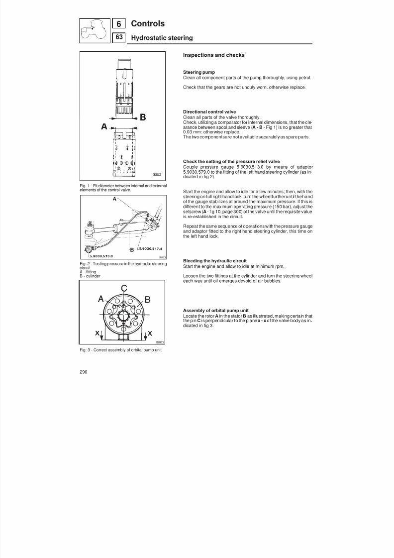
8/19/2019 Agrocompact f60 f70 f80 f90 Repair manual
http://slidepdf.com/reader/full/agrocompact-f60-f70-f80-f90-repair-manual 290/519
Fig. 1 - Fit diameter between internal and externalelements of the control valve.
Fig. 2 - Testing pressure in the hydraulic steeringcircuit.A - fittingB - cylinder
Fig. 3 - Correct assembly of orbital pump unit
Inspections and checks
Steering pumpClean all component parts of the pump thoroughly, using petrol.
Check that the gears are not unduly worn, otherwise replace.
Directional control valveClean all parts of the valve thoroughly.Check, utilizing a comparator for internal dimensions, that the cle -arance between spool and sleeve ( A - B - Fig 1) is no greater that0.03 mm: otherwise replace.The twocomponentsare notavailableseparatelyas spare parts.
Check the setting of the pressure relief valveCouple pressure gauge 5.9030.513.0 by means of adaptor5.9030.579.0 to the fitting of the left hand steering cylinder (as in -dicated in fig 2).
Start the engine and allow to idle for a few minutes; then, with thesteering on full right hand lock, turn the wheelfurtheruntil thehand
of the gauge stabilizes at around the maximum pressure. If this isdifferent to the maximum operating pressure (150 bar), adjust thesetscrew ( A - fig 10, page 300) of the valve until the requisite valueis re-established in the circuit.
Repeat the same sequence of operationswith the pressure gaugeand adaptor fitted to the right hand steering cylinder, this time onthe left hand lock.
Bleeding the hydraulic circuitStart the engine and allow to idle at minimum rpm.
Loosen the two fittings at the cylinder and turn the steering wheeleach way until oil emerges devoid of air bubbles.
Assembly of orbital pump unitLocate the rotor A in thestator B as illustrated, making certain thatthe pin C is perpendicular to the plane x - x of the valve body as in -dicated in fig 3.
290
63
6 Controls
Hydrostatic steering
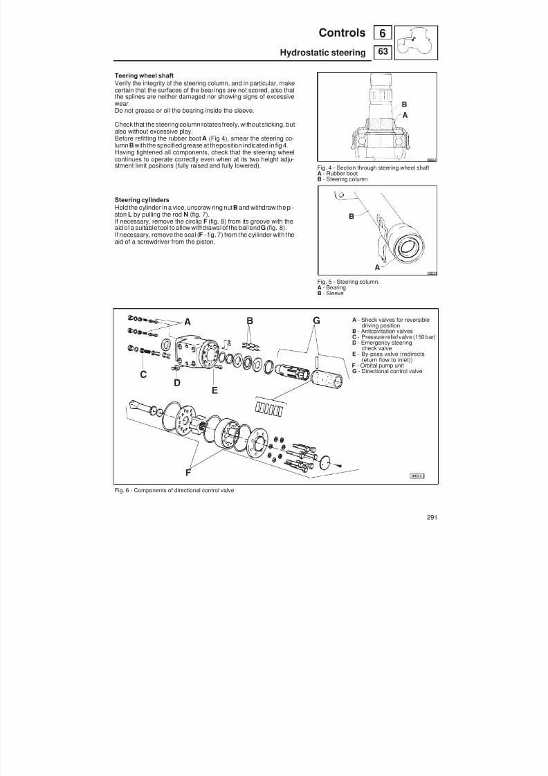
8/19/2019 Agrocompact f60 f70 f80 f90 Repair manual
http://slidepdf.com/reader/full/agrocompact-f60-f70-f80-f90-repair-manual 291/519
Teering wheel shaftVerify the integrity of the steering column, and in particular, makecertain that the surfaces of the bearings are not scored, also thatthe splines are neither damaged nor showing signs of excessivewear.Do not grease or oil the bearing inside the sleeve.
Check that the steering column rotates freely, without sticking, butalso without excessive play.Before refitting the rubber boot A (Fig 4), smear the steering co -lumn B with the specified grease at theposition indicated in fig 4.Having tightened all components, check that the steering wheelcontinues to operate correctly even when at its two height adju -stment limit positions (fully raised and fully lowered).
Steering cylindersHold the cylinder in a vice, unscrew ring nut B and withdraw thepi -ston L by pulling the rod N (fig. 7).If necessary, remove the circlip F (fig. 8) from its groove with theaid ofa suitable tool to allow withdrawal of the ball end G (fig. 8).If necessary, remove the seal ( F - fig. 7) from the cyilinder with theaid of a screwdriver from the piston.
Fig. 6 - Components of directional control valve
Fig. 4 - Section through steering wheel shaftA - Rubber bootB - Steering column
Fig. 5 - Steering column.A - BearingB - Sleeve
A - Shock valves for reversibledriving position
B - Anticavitation valvesC - Pressure reliefvalve (150 bar)D - Emergency steering
check valveE - By-pass valve (redirects
return flow to inlet))F - Orbital pump unitG - Directional control valve
291
63
6Controls
Hydrostatic steering
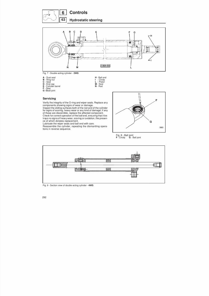
8/19/2019 Agrocompact f60 f70 f80 f90 Repair manual
http://slidepdf.com/reader/full/agrocompact-f60-f70-f80-f90-repair-manual 292/519
Fig. 7 - Double-acting cylinder - 2WD .
A - Dust seal H - Ball endB - Ring nut I - CirclipC - Seal L - PistonD - End cap M - SealE - Cylinder barrel N - RodF - SealG -Bball joint
ServicingVerify the integrity of the O-ring and wiper seals. Replace anycomponents showing signs of wear or damage.Inspect the sliding surfaces both of the rod and of the cylinderfor signs of scoring, heavy wear or any kind of damage; if anyof these are discernible, replace the affected component.Check for correct operation of the ball end, ensuring that it be -trays no signs of heavy wear, scoring or oxidation, the presen -ce of which dictates replacement.Lubricate the wiper seals and ball end with care.Reassemble the cylinder, repeating the dismantling opera -tions in reverse sequence.
Fig. 8 - Ball jointF - Circlip G - Ball joint
Fig. 9 - Section view of double-acting cylinder - 4WD .
292
63
6 Controls
Hydrostatic steering

8/19/2019 Agrocompact f60 f70 f80 f90 Repair manual
http://slidepdf.com/reader/full/agrocompact-f60-f70-f80-f90-repair-manual 293/519
Instructions for the hydro -static steering distributor
assembly
3 - Press the spring blades to align incentre position.
6 -Fit the spacer onte the distributor.
9 - Axial bearing installation.
1 - Insert the spring set (blue) as shownin figure.
4 - Reassemble the rotary distributor.
7 - Insert the drive pin into the cylinder
10 - Use no. 5.9030.480.0 tool to fit theseal ring.
2 -Insert first the two external spring bla -des into the rotary distributor and subse -quently the two internal ones.
5 - Act onspringsin sucha waythey areprevented from projecting outwards withrespect to the rotary distributor outside
surface.
8 - Install the axial bearing following theassembly order shown in next figure.
11 - Insert the O-ring after fitting the toolsleeve into the distributor case.
293
63
6Controls
Hydrostatic steering

8/19/2019 Agrocompact f60 f70 f80 f90 Repair manual
http://slidepdf.com/reader/full/agrocompact-f60-f70-f80-f90-repair-manual 294/519
12 - O-ring as installed on the plug.
15 - Insert the distributor from the bot -tom trying to make installation easier al -ternately rotating in both directions.
18 - Screw down the valve grub screw inits seat.
21 - Fit the seal ring inthe related seat.
13 - Insert the O-ring into the sleeve andpress until it is fully inserted.
16 - Press the distributor until the plug ispushed out of the opposite side.
19 - Insert the balls as shown by the ar -row.
22 - Fit the spacer in such a way the ho -les init arein the sameline asthe corre -sponding grooves.
14 - Pull out the tool.
17 - Turn the distributor case upsidedown holding the rotary distributor inplace and iserting the shunt valve as in -
dicated by the arrow in figure.
20 - Insertthe two pins inthe sameposi -tions as previously shown.
23 - Insert the drive shaft in the distribu -tor so that the notching may engage intothe pin in a position being parallel to thedistributor face.
294
63
6 Controls
Hydrostatic steering

8/19/2019 Agrocompact f60 f70 f80 f90 Repair manual
http://slidepdf.com/reader/full/agrocompact-f60-f70-f80-f90-repair-manual 295/519
24 - Place the fork as shown in figure soas the drive shaft may be held in posi -tion.
27 - Place the spacer ring, (only for tho -se models which the spacer is fitted).
30 - Fix the cover with the securingscrews by tightening to the recommen -ded torque.
33 - Install the pressure relief valve.
25 - After inserting the two O-rings pro -perly lubricated into the oil flow controlshutter fit the stator positioning asshown in figure.
28 - Install the pin screw in the specialhole (the ball valve hole).
31 - Fit the seal ring.
34 - Insert the spring.
26 - The rotor shouldbe placedto the sta -tor and then swiveled with regard to thedrive shaft as shown in figure.
29 - Fit the cover.
32 - Insert the seal ring into its seat.
35 - Fit the pressure relief valve capscrew.
295
63
6Controls
Hydrostatic steering

8/19/2019 Agrocompact f60 f70 f80 f90 Repair manual
http://slidepdf.com/reader/full/agrocompact-f60-f70-f80-f90-repair-manual 296/519
A - pressure relief valve F - return flowB - check valve L - to left hand cylinderC - from pump R - to right hand cylinderD - anticavitation valve P - pumpE - emergency steering check valve T - discharger
Fig. 10 - Distributor cross-section.
296
63
6 Controls
Hydrostatic steering
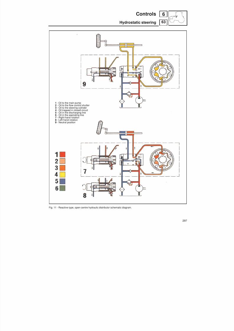
8/19/2019 Agrocompact f60 f70 f80 f90 Repair manual
http://slidepdf.com/reader/full/agrocompact-f60-f70-f80-f90-repair-manual 297/519
1 - Oil to the main pump2 - Oil to the flow control shutter3 - Oil to the steering cylinder4 - Oil trapped in closed circuit5 - Oil in the discharging line6 - Oil in the aspirating line7 - Right-hand rotation
8 - Left-hand rotation9 - Neutral position
Fig. 11 - Reactive-type, open-centre hydraulic distributor schematic diagram.
297
63
6Controls
Hydrostatic steering
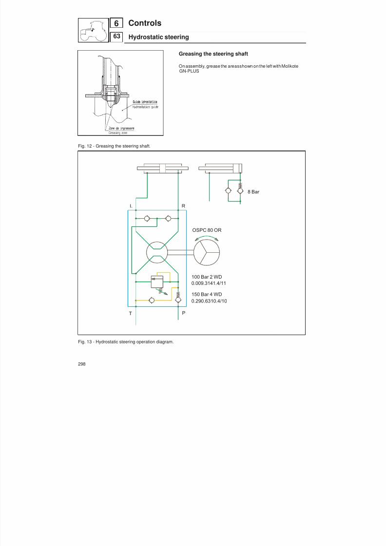
8/19/2019 Agrocompact f60 f70 f80 f90 Repair manual
http://slidepdf.com/reader/full/agrocompact-f60-f70-f80-f90-repair-manual 298/519
Greasing the steering shaft
On assembly, grease the areasshown on the left with MolikoteGN-PLUS
Fig. 12 - Greasing the steering shaft.
Fig. 13 - Hydrostatic steering operation diagram.
298
63
6 Controls
Hydrostatic steering
L R
T P
8 Bar
OSPC 80 OR
100 Bar 2 WD
0.009.3141.4/11
150 Bar 4 WD
0.290.6310.4/10
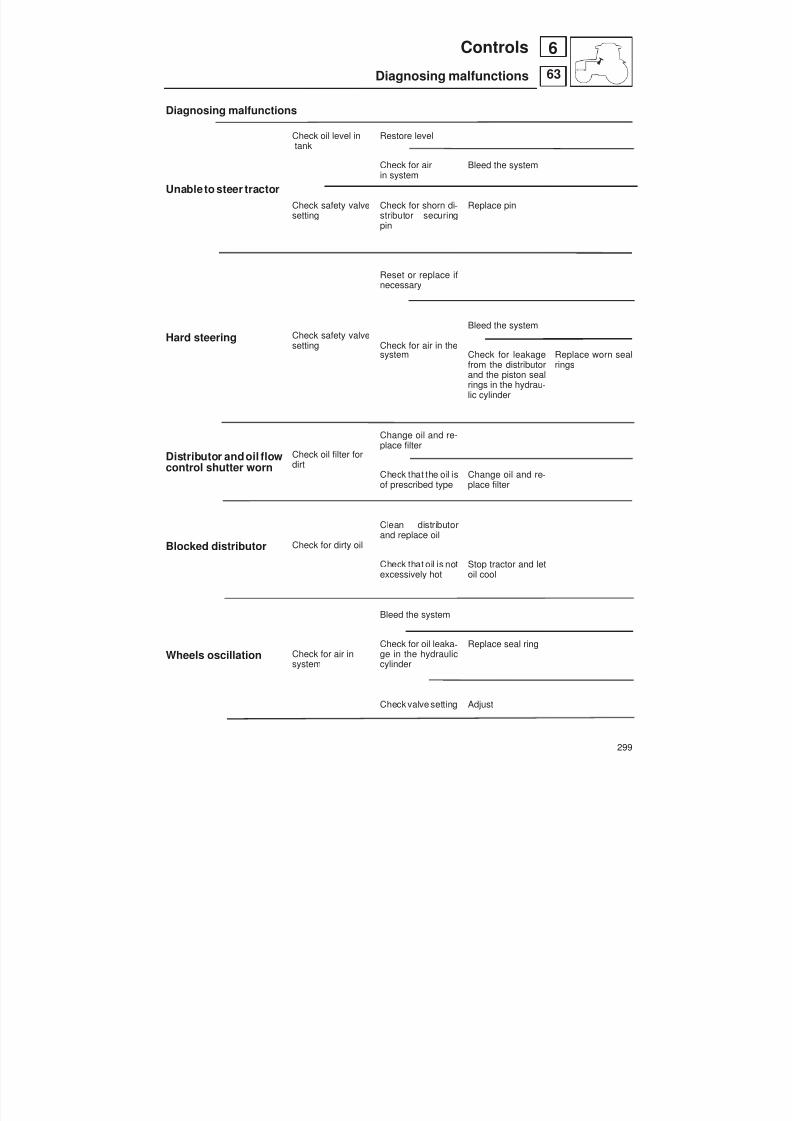
8/19/2019 Agrocompact f60 f70 f80 f90 Repair manual
http://slidepdf.com/reader/full/agrocompact-f60-f70-f80-f90-repair-manual 299/519
Diagnosing malfunctions
Unable to steer tractor
Hard steering
Distributor andoil flowcontrol shutter worn
Blocked distributor
Wheels oscillation
Check oil level intank
Check safety valvesetting
Check safety valvesetting
Check oil filter fordirt
Check for dirty oil
Check for air insystem
Restore level
Check for airin system
Check for shorn di -stributor securingpin
Reset or replace ifnecessary
Check for air in thesystem
Change oil and re-place filter
Check that the oil isof prescribed type
Clean distributorand replace oil
Check that oil is notexcessively hot
Bleed the system
Check for oil leaka -ge in the hydrauliccylinder
Check valve setting
Bleed the system
Replace pin
Bleed the system
Check for leakagefrom the distributorand the piston sealrings in the hydrau -lic cylinder
Change oil and re -place filter
Stop tractor and letoil cool
Replace seal ring
Adjust
Replace worn sealrings
299
63
6Controls
Diagnosing malfunctions
8/19/2019 Agrocompact f60 f70 f80 f90 Repair manual
http://slidepdf.com/reader/full/agrocompact-f60-f70-f80-f90-repair-manual 300/519
Mechanical controlsGiven the constructional simplicity of these controls, we present a series of figures illustrating the individual compo -nents of the controls.Only some of these controls require adjustment; for instructions for these adjustments, refer to the chapter dealing withcorresponding unit.
Fig. 1 Mini-reduction/shuttle control Fig. 2 Gearshift controls Fig. 3 Range gear control Fig. 4 Internal gear controls Fig. 5 Internal shuttle control Fig. 6 Differential lock control Fig. 7 Internal differential lock control Fig. 8 Handbrake control Fig. 9 Handbrake control (part under footplate) Fig. 10 4WD - Front differential lock Fig. 11 4WD - Drive shaft Fig. 12 4WD - Power take-off Fig. 13 4WD engagement control Fig. 14 2-speed P.T.O.Fig. 15 3-speed P.T.O. - 60 HP Fig. 16 3-speed P.T.O. - 70 - 80 - 90 HP Fig. 17 2-speed + groundspeed P.T.O.Fig. 18 2-speed + groundspeed P.T.O. (internal controls)
Fig. 19 Groundspeed P.T.O. control Fig. 20 Groundspeed P.T.O. internal control Fig. 21 Front P.T.O.Fig. 22 Throttle controls Fig. 23 Hand throttle control Fig. 24 Electronic hand throttle control Fig. 25 Accelerator pedal control Fig. 26 Lift control levers Fig. 27 Auxiliary service control valve - flow control valve Fig. 28 Lift control levers under footplate Fig. 29 Auxiliary service control valves - 6-way
Fig. 30 Auxiliary service control valves - 4-way
WARNING: It is important that those tie-rods fitted with adjustable forks are adjusted so that their respective control le -vers can be moved through their entire range from min. to max. without obstruction.
300
64
6 Controls
Mechanical controls
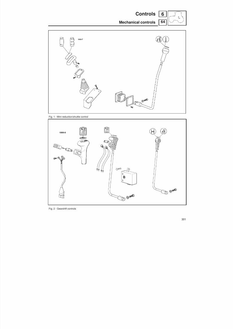
8/19/2019 Agrocompact f60 f70 f80 f90 Repair manual
http://slidepdf.com/reader/full/agrocompact-f60-f70-f80-f90-repair-manual 301/519
Fig. 1 - Mini-reduction/shuttle control
Fig. 2 - Gearshift controls
301
64
6Controls
Mechanical controls

8/19/2019 Agrocompact f60 f70 f80 f90 Repair manual
http://slidepdf.com/reader/full/agrocompact-f60-f70-f80-f90-repair-manual 302/519
Fig. 3 - Range gear control
Fig. 4 - Internal gear controls.
302
64
6 Controls
Mechanical controls

8/19/2019 Agrocompact f60 f70 f80 f90 Repair manual
http://slidepdf.com/reader/full/agrocompact-f60-f70-f80-f90-repair-manual 303/519
Fig. 5 - Internal shuttle control.
Fig. 6 - Differential lock control.
303
64
6Controls
Mechanical controls
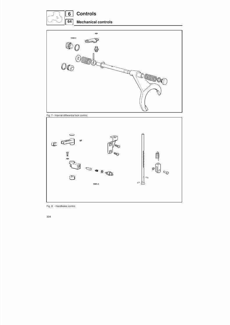
8/19/2019 Agrocompact f60 f70 f80 f90 Repair manual
http://slidepdf.com/reader/full/agrocompact-f60-f70-f80-f90-repair-manual 304/519
Fig. 7 - Internal differential lock control.
Fig. 8 - Handbrake control.
304
64
6 Controls
Mechanical controls

8/19/2019 Agrocompact f60 f70 f80 f90 Repair manual
http://slidepdf.com/reader/full/agrocompact-f60-f70-f80-f90-repair-manual 305/519
Fig. 9 - Handbrake control (part under footplate).
Fig. 10 - 4WD - Front differential lock.
305
64
6Controls
Mechanical controls

8/19/2019 Agrocompact f60 f70 f80 f90 Repair manual
http://slidepdf.com/reader/full/agrocompact-f60-f70-f80-f90-repair-manual 306/519
Fig. 11 - 4WD - Drive shaft
Fig. 12 - 4WD - Power take-off.
306
64
6 Controls
Mechanical controls

8/19/2019 Agrocompact f60 f70 f80 f90 Repair manual
http://slidepdf.com/reader/full/agrocompact-f60-f70-f80-f90-repair-manual 307/519
Fig. 13 - 4WD engagement control.
Fig. 14 - 2-speed P.T.O..
307
64
6Controls
Mechanical controls
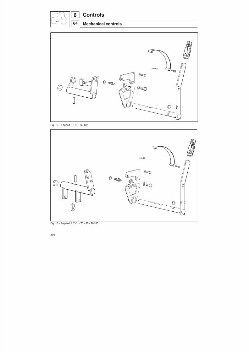
8/19/2019 Agrocompact f60 f70 f80 f90 Repair manual
http://slidepdf.com/reader/full/agrocompact-f60-f70-f80-f90-repair-manual 308/519
Fig. 15 - 3-speed P.T.O. - 60 HP.
Fig. 16 - 3-speed P.T.O. - 70 - 80 - 90 HP
308
64
6 Controls
Mechanical controls
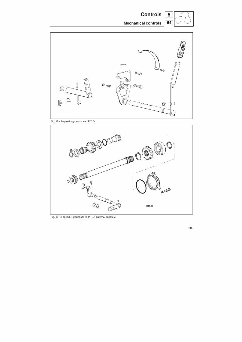
8/19/2019 Agrocompact f60 f70 f80 f90 Repair manual
http://slidepdf.com/reader/full/agrocompact-f60-f70-f80-f90-repair-manual 309/519
Fig. 17 - 2-speed + groundspeed P.T.O..
Fig. 18 - 2-speed + groundspeed P.T.O. (internal controls).
309
64
6Controls
Mechanical controls
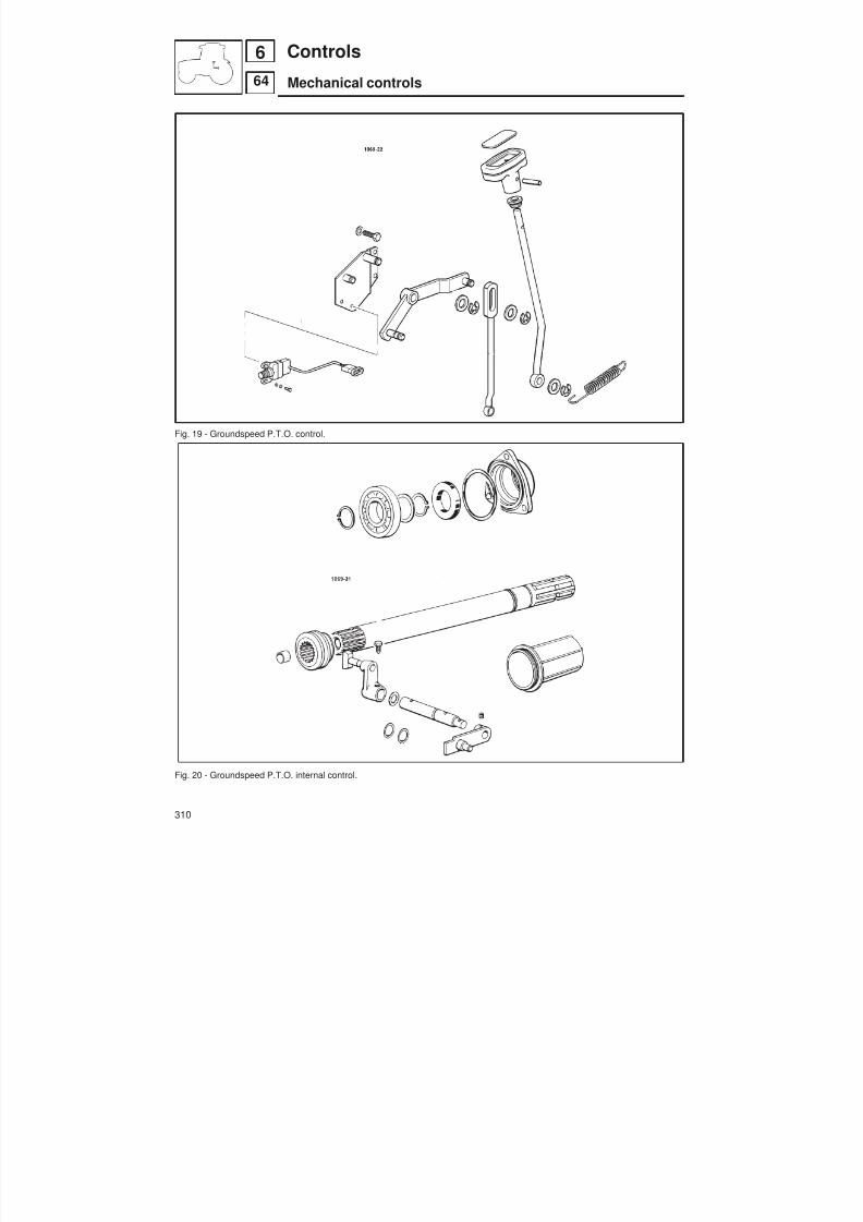
8/19/2019 Agrocompact f60 f70 f80 f90 Repair manual
http://slidepdf.com/reader/full/agrocompact-f60-f70-f80-f90-repair-manual 310/519
Fig. 19 - Groundspeed P.T.O. control.
Fig. 20 - Groundspeed P.T.O. internal control.
310
64
6 Controls
Mechanical controls
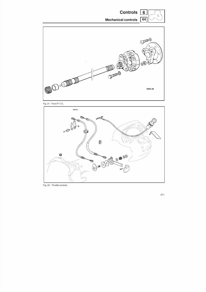
8/19/2019 Agrocompact f60 f70 f80 f90 Repair manual
http://slidepdf.com/reader/full/agrocompact-f60-f70-f80-f90-repair-manual 311/519
Fig. 21 - Front P.T.O..
Fig. 22 - Throttle controls.
311
64
6Controls
Mechanical controls

8/19/2019 Agrocompact f60 f70 f80 f90 Repair manual
http://slidepdf.com/reader/full/agrocompact-f60-f70-f80-f90-repair-manual 312/519
Fig. 23 - Hand throttle control.
Fig. 24 - Electronic hand throttle control.
312
64
6 Controls
Mechanical controls

8/19/2019 Agrocompact f60 f70 f80 f90 Repair manual
http://slidepdf.com/reader/full/agrocompact-f60-f70-f80-f90-repair-manual 313/519
Fig. 25 - Accelerator pedal control.
Fig. 26 - Lift control levers.
313
64
6Controls
Mechanical controls

8/19/2019 Agrocompact f60 f70 f80 f90 Repair manual
http://slidepdf.com/reader/full/agrocompact-f60-f70-f80-f90-repair-manual 314/519
Fig. 27 - Auxiliary service control valve Fig. 28 - Lift control levers.- flow control valve
314
64
6 Controls
Mechanical controls

8/19/2019 Agrocompact f60 f70 f80 f90 Repair manual
http://slidepdf.com/reader/full/agrocompact-f60-f70-f80-f90-repair-manual 315/519
Fig. 29 - Auxiliary service control valves - 6-way.
Fig. 30 - Auxiliary service control valves - 4-way.
315
64
6Controls
Mechanical controls

8/19/2019 Agrocompact f60 f70 f80 f90 Repair manual
http://slidepdf.com/reader/full/agrocompact-f60-f70-f80-f90-repair-manual 316/519
Electro-hydraulic controls
Front P.T.O. clutch engagement controlThe front P.T.O. can only be engaged when the engine is running. Pressing the pushbutton engages the front P.T.O..The integral light illuminates to indicate that the P.T.O. is engaged.
Rear P.T.O. clutch engagement controlThe rear P.T.O. can only be engaged when the engine is running. Pressing the pushbutton engages the rear P.T.O..The integral light illuminates to indicate that the P.T.O. is engaged.
Differential lock engagement controlPressing the pushbutton engages the front and rear differential locks. The integral light illuminates to indicate that thelocks are engaged. Pressing the pushbutton again disengages the locks.
Front-wheel drive engagement controlPushbutton with integral indicator light.Press to engage front-wheel drive; press again to disengage.
N.B. Engagement of the above devices is also signalled by indicator lights on the console.
Rear P.T.O. engagement controlPushbutton with integral indicator light.Press to engage the rear P.T.O.; press again to disengage.The P.T.O. may only be engaged when the engine is running.
Gearbox
The POWERSHIFTtransmission offers the possibility toselect each speed in , or (using the gear and rangelever) without having to depress the clutch pedal simply by pressing the electro-hydraulic control switch.This is achieved by way of three multi-plate clutches.
Electro-hydraulic shuttleAs an alternative to the mechanical shuttle, all transmission types may be equipped with an electro-hydraulically con -trolled shuttle. This comprises an electronically controlled system, where two hydraulically controlled actuators act onthe gearbox clutch and the direction selector rod. The shuttle control lever is located on the left below the steering co -lumn.
Front and rear liftThe front lift is operated by way of the control lever of the auxiliary service control valves located on the right of the dri -ving seat, after first opening the shut-off cock in the oil delivery line to the front lift.The mechanical rear lift is operated by controls located to the right of the driving seat.For tractors equipped with electronic lifts, see p. 258 for a description of the controls.
Electro-hydraulic controls for adjustment of the right-hand lift rod and the lateral stabilisers.The adjustable lift rod consists of a double-acting hydraulic cylinder, while the stabilisers are single-acting hydrauliccylinders.
In the version in which the oil is drawn from the auxiliary service control valves, the control system is equipped with aflow divider valve which, operated by a solenoid valve controlled from a switch, sends oil to the lift rod or the stabilisers.The linkage can then be adjusted using the first control valve lever.
In the version with full electro-hydraulic control, the system is equipped with a specific control unit, which allows directadjustment of the linkage.
316
68
6 Controls
Electro-hydraulic controls

8/19/2019 Agrocompact f60 f70 f80 f90 Repair manual
http://slidepdf.com/reader/full/agrocompact-f60-f70-f80-f90-repair-manual 317/519
A - Main oil filter on supply circuitB - Hydraulic pump for auxiliary service
control valve and power liftC - Hydraulic pump for hydrostatic
steering and electro-hydraulic controlsE - Hydrostatic steering control valveF - Steering cylindersG - Oil coolerH - Pressure control valvesI - Gearbox lubricationL - Hydraulic power unitM - Differential locksN - 4WD engagementO - Rear P.T.O. clutchP - 6-way auxiliary service control valveQ - Front lift hydraulic control valveR - Lifting cylinder
Fig. 1 - Hydraulic circuit diagram (with electronic lift - STANDARD version).
L R
T P
5 bar 16 bar
P.T.O.
Rapp. 1/1.0732 (44/41)
8 Bar
OSPC 80 OR
100 Bar 2 WD0.009.3141.4/11
150 Bar 4 WD0.290.6310.4/10
27 L/min.
150 Micr.
3 2 c c
ø 1.1
Main shaft
Sec. shaft
N.giri/min.pompe:2522
11 cm 3
x
15 Micr.
2.4419.480.0
35 L/min.14 cm 319 cm 3
47 L/min.
11 bar
Rh Lf
A
P T
A
P T
I n n
.
D i s
.
Front
Diff.look
Rear D i s
.
I n n
.
4 Wd
A
P T
4RM 2RM
F
E
MN
O
I
L
H
G
B
C
A

8/19/2019 Agrocompact f60 f70 f80 f90 Repair manual
http://slidepdf.com/reader/full/agrocompact-f60-f70-f80-f90-repair-manual 318/519
A - Main oil filter on supply circuitB - Hydraulic pump for auxiliary service
control valve and power liftC - Hydraulic pump for hydrostatic steering
and electro-hydraulic controlsD - H-M-LE - Hydrostatic steering control valveF - Steering cylinders
G - Suction line filterG1 - Delivery line filterH - Pressure control valvesI - Gearbox lubricationL - Hydraulic power unitM - Differential locksN - 4WD engagementO - Rear P.T.O. clutchP - 6-way auxiliary service control valveQ - Front lift hydraulic control valveR - Lifting cylinderS - Shut-off valve for front liftT - Control valve for hydraulic trailer brakingU - Front lift cylindersV1 - Anti-shock valve for front liftV2 - Lowering speed control valve for front liftZ - Hydraulic cylinders for adjustable stabilisersW - Hydraulic cylinder for adjustable lift rodX - Solenoid valve for switching flow between
stabilisers/lift rodY - Supplementary hydraulic control valveJ1 - Supplementary hydraulic lineJ2 - Supplementary hydraulic line for free return
J 3 - Hydraulic unloader (oil level pump)
Fig. 2 - Hydraulic circuit diagram (version with full complement of optional equipment).
318
Controls
Electro-hydraulic controls
668
A
P T
A
P T
Trailer brake
Tractor brake
2.3719.810.0/10 (Italia)2.3719.550.0/20 (Francia)
70 Bar
190 Bar T
E
P
A AB B
1
0 0
2 2
1
1
0
N
2.3719.730.0
H M L
P T
A A
I n n
.
D i s
.
Front
Diff.look
Rear D i s
.
I n n
.
4 Wd
TP
7 0 0 c c
A
B
PT
V max V max V max13.9 cm14.7 cm11.6 cm 3 3 3
11+11 cm27+27 L/min.3
Ø 1
0.009.9020.4
Rh side
Rh side Lf side
Free return Rh side
0.010.5140.4
0 . 0
1 1
. 3 4 6 8
. 4
0.011.3671.4/10
0.35 bar
P
Y
Rh Lf Rh
Y
P1P2
C3
C2
ø1 ø1
C1C2
Rear free return
Fto A2
L R
T P
5 bar 16 bar
P.T.O.
Rapp. 1/1.0732 (44/41)
A
P T
11 bar
8 Bar
OSPC 80 OR
100 Bar 2 WD0.009.3141.4/11
150 Bar 4 WD0.290.6310.4/10
27 L/min.
150 Micr.
3 2 c c
ø 1.1
Main shaft
Sec. shaft
N.giri/min.pompe:2522
11 cm 3
x
15 Micr.
2.4419.480.0
Freno inser.=13 bar,disinse=3 bar
F
4RM 2RM
E
M
N
O
I
L
H
G
BC
A
Y
Z
W
X
U
V2
S
J1 J
J2
T
D
J3
G1
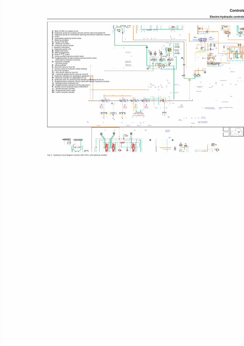
8/19/2019 Agrocompact f60 f70 f80 f90 Repair manual
http://slidepdf.com/reader/full/agrocompact-f60-f70-f80-f90-repair-manual 319/519
A
P T
A
P T
Trailer brake
2.372.37
I n n
.
D i s
.
Front
Diff.look
Rear D i s
.
I n n
.
4 Wd
V max V max V max13.9 cm14.7 cm11.6 cm 3 3 3
11+11 cm27+27 L/min.
3
Front free return Rh side
P
RhRh
L R
T P
5 bar 16 bar
P.T.O.
Rapp. 1/1.0732 (44/41)
A
P T
11 bar
OSPC 80 OR
100 Bar 2 WD0.009.3141.4/11
150 Bar 4 WD0.290.6310.4/10
27 L/min.
150 Micr.
3 2 c c
ø 1.1
Main shaft
Sec. shaft
N.giri/min.pompe:2522
11 cm 3
15 Micr.2.4419.480.0
F
E
MN
O
I
L
H
BLf C
G
Z
J1
A
A3B3
1
0
2
E
RV1
R
T
E
T
Priority flow
R e s i d u a l f l o w
VDP
Pr
190bar
A2
1
0
2
B2 A1
1
0
2
B1
T
DSE190 Bar
Lh side Rh side Joystick Rh side
5 566 4 4
Tasto basculante
2.3729.500.0185 Bar
ø1.8
P
6
T
A A
PT
T PP T
T P
A
P T
A
D a l l a P o m p a
F r o m P u m p
Stabilizzatore RxRight Stabilizer
P T
A A
TP TP
A
P
A
H M L
M12x1.5 M12x1.5 M12x1.5
AV RM Azionam.
M12x1.5
Frizione
D
K
K1
K2
K3
Q
Y
A - Main oil filter on supply circuitB - Hydraulic pump for auxiliary service control valve and power liftC - Hydraulic pump for hydrostatic steering and electro-hydraulic controlsD - H-M-LE - Hydrostatic steering control valveF - Steering cylindersG - Suction line filterG1 - Delivery line filterH - Pressure control valvesI - Gearbox lubricationL - Hydraulic power unitM - Differential locksN - 4WD engagementO - Rear P.T.O. clutchP - 6-way auxiliary service control valveP1 -Supplementary 6-way auxiliary service control valve
(with electro-hydraulic controls)Q - Hydraulic unloader
(oil level pump)R - Lifting cylinderS - Shut-off valve for front liftT - Control valve for hydraulic trailer brakingU - Front lift cylindersV1 - Anti-shock valve for front liftV2 - Lowering speed control valve for front liftZ - Hydraulic cylinders for adjustable stabilisersW - Hydraulic cylinder for adjustable lift rodX - Solenoid valve for switching flow between stabilisers/rh lift rodY - Supplementary hydraulic control valve with electro-hydraulic controls
J1 - Supplementary hydraulic lineJ2 - Supplementary hydraulic line for free returnK - Shuttle control solenoid valve (FWD/REV)K1 - Shuttle actuator cylinderK2 - Proportional clutch valveK3 - Clutch actuator cylinder
Fig. 3 - Hydraulic circuit diagram (version with H-M-L and hydraulic shuttle).

8/19/2019 Agrocompact f60 f70 f80 f90 Repair manual
http://slidepdf.com/reader/full/agrocompact-f60-f70-f80-f90-repair-manual 320/519
A - Check valveB - Check valveC - Gearbox lubrication pressure control valve (5 bar)D - Sequence valve (16 bar)P - PumpT - Oil returnL1 - Gearbox lubricationL2 - P.T.O. lubrication1 - Rear P.T.O.2 - Differential lock3 - 4WD
Fig. 4 - Hydraulic circuit on right-hand side of gearbox.
320
Controls
Electro-hydraulic controls
668

8/19/2019 Agrocompact f60 f70 f80 f90 Repair manual
http://slidepdf.com/reader/full/agrocompact-f60-f70-f80-f90-repair-manual 321/519
Fig. 5 - Hydraulic components on upper part of gearbox casing - Version with POWERSHIFT.
ASSE MOTORE
ASSE MOTORE
ASSE MOTORE
INVERSORE
CAMBIO
AR M
I N I
L u
b r
i f .
N°6 viti M12x30
N°2 viti M12x55
SMONTAGGIO
Lubrif.
Lubrificaz.
High
Low
Medium
2.3719.670.0
2.3719.670.0
z0

8/19/2019 Agrocompact f60 f70 f80 f90 Repair manual
http://slidepdf.com/reader/full/agrocompact-f60-f70-f80-f90-repair-manual 322/519
5
N m
Alimentaz.
12 V - 21 W
ASSE MOTORE
ASSE MOTORE
ASSE MOTORE
5 N m
5 N m
6 7
CAMBIO
L u b r i f .
N°1 vite M12x40
I n v e r s .
I n v e r s .
N°2 viti M12x55
N
p
3 2
0.008.1646.0sensore velocita
Fig. 6 - Hydraulic controls for shuttle and POWERSHIFT.
322
Controls
Electro-hydraulic controls
668
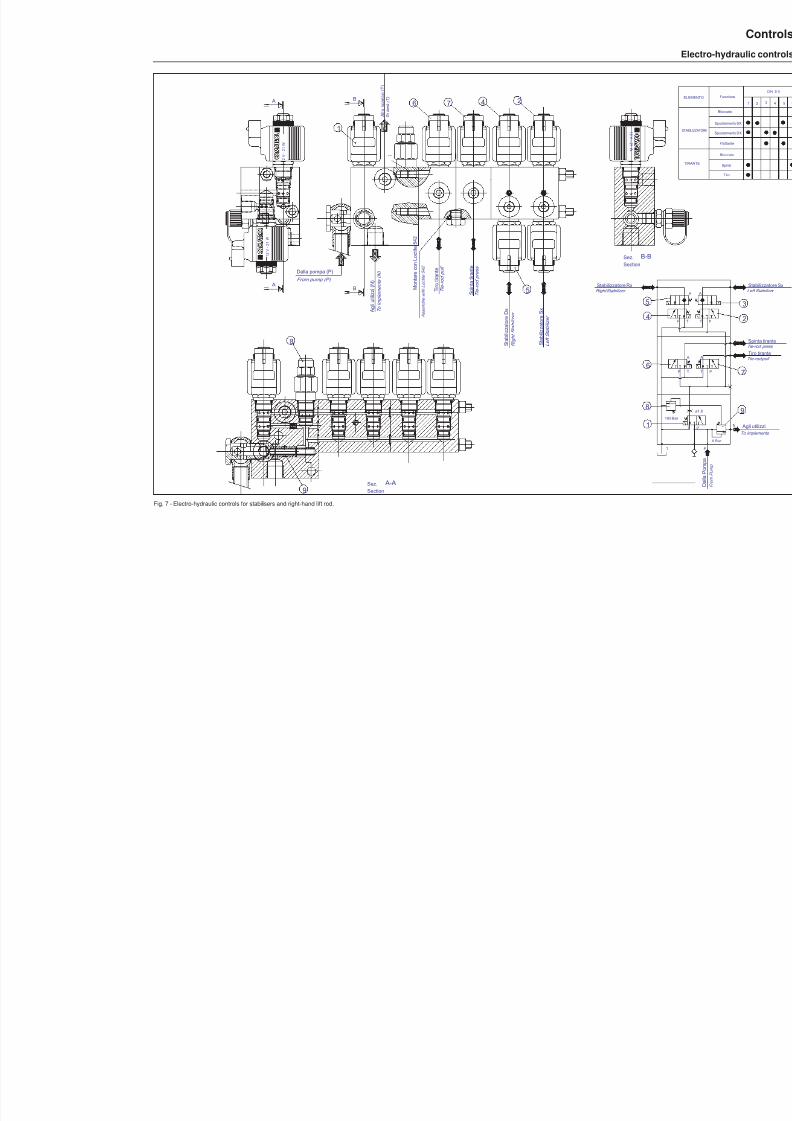
8/19/2019 Agrocompact f60 f70 f80 f90 Repair manual
http://slidepdf.com/reader/full/agrocompact-f60-f70-f80-f90-repair-manual 323/519
Sez.Section
B-B
5
1 2 V -2 1 W
1 2 V - 2 1
W
1 2 V - 2 1
W
Sez.Section
A-A
**
M o n t a r e c o n L o c t i t e 5 4 2
A s s e m b l e
w i t h
L o c t i t e 5 4 2
185
T
Stabilizzatore RxRight Stabilizer
B
B
A g l i u t i l i z z i ( N )
T o i m
p l e m e n t s
( N )
T i e - r o d p u
l l
T i e - r o d p r e s
s
S p i n t a t i r a n t e
T i r o t i r a n t e
T o t a n k ( T
)
A l l o s c a r i c o
( T )
Dalla pompa (P)From pump (P)
A
A
S t a b i l i z z a t o r e S x
L e f t S t a b i l i z e r
S t a b i l i z z a t o r e D x
R i g h t S t a b i l i z e r
9
8
6 47 2
1
5
4
6
8
1
Fig. 7 - Electro-hydraulic controls for stabilisers and right-hand lift rod.
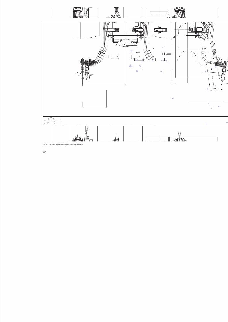
8/19/2019 Agrocompact f60 f70 f80 f90 Repair manual
http://slidepdf.com/reader/full/agrocompact-f60-f70-f80-f90-repair-manual 324/519
45
435
ø 2 2
5 0 x
1 . 5
ø 3 8
41
31 2615
4.5
ø 5 5 16
42
8877.5
Tubo ø8x1
ø 5 0 h 1 1
19.5 mm=3Kg
89.2
32.99x2.62
21.89x2.62
195
11
114
46.07
1 3 4
1 2 9
1 1 0
1 0 5
240 ±0.5
34
Fig. 8 - Hydraulic system for adjustment of stabilisers.
324
Controls
Electro-hydraulic controls
668
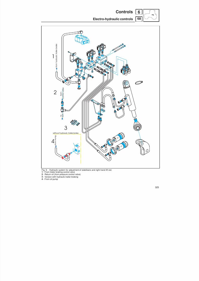
8/19/2019 Agrocompact f60 f70 f80 f90 Repair manual
http://slidepdf.com/reader/full/agrocompact-f60-f70-f80-f90-repair-manual 325/519
f r o m h y d r a u l i c t r a i l e r b r a k e
D X
S X
f r o m P u m p
without hydraulic trailer brake
f r o m
c o n t r o l v a l v e
t o t a n k
1
2
3
4
Fig. 9 - Hydraulic system for adjustment of stabilisers and right-hand lift rod.1 - From trailer braking control valve2 - Return oil (from pressure control valve)3 - Version with hydraulic trailer braking4 - From oil pump
325
68
6Controls
Electro-hydraulic controls

8/19/2019 Agrocompact f60 f70 f80 f90 Repair manual
http://slidepdf.com/reader/full/agrocompact-f60-f70-f80-f90-repair-manual 326/519
L UB RI C .
L U B R I C A T I O N
F E E D
Hi gh
L ow
M e d i um
High
Low
Fig. 10 - POWERSHIFT solenoid valves - LOW clutch engagement
326
68
6 Controls
Electro-hydraulic controls

8/19/2019 Agrocompact f60 f70 f80 f90 Repair manual
http://slidepdf.com/reader/full/agrocompact-f60-f70-f80-f90-repair-manual 327/519
L UB RI F I C .
L U B R I F I C A T I O N
F E E D
Hi gh
L ow
M e d i um
T
High
Low
Fig. 11 - POWERSHIFT solenoid valves - MEDIUM clutch engagement
327
68
6Controls
Electro-hydraulic controls

8/19/2019 Agrocompact f60 f70 f80 f90 Repair manual
http://slidepdf.com/reader/full/agrocompact-f60-f70-f80-f90-repair-manual 328/519
L UB RI C .
L U B R I C A T I O N
F E E D
Hi gh
L ow
M e d i um
T
High
Low
Fig. 12 - POWERSHIFT solenoid valves - HIGH clutch engagement .
328
68
6 Controls
Electro-hydraulic controls

8/19/2019 Agrocompact f60 f70 f80 f90 Repair manual
http://slidepdf.com/reader/full/agrocompact-f60-f70-f80-f90-repair-manual 329/519
12 V -
12 V -
1 2 V - 2 1 W
Low
AV
RM
HIGH
1
2
3
4
5
8
1 - Clutch control piston
2 - Position sensor controlling oil flow to actuator 53 - Proportional solenoid valve4 - REV solenoid valve5 - Shuttle control actuator6 - FWD solenoid valve7 - LOW solenoid valve (POWERSHIFT)8 - HIGH solenoid valve
Fig. 13 - Control system for POWERSHIFT with hydraulic shuttle.
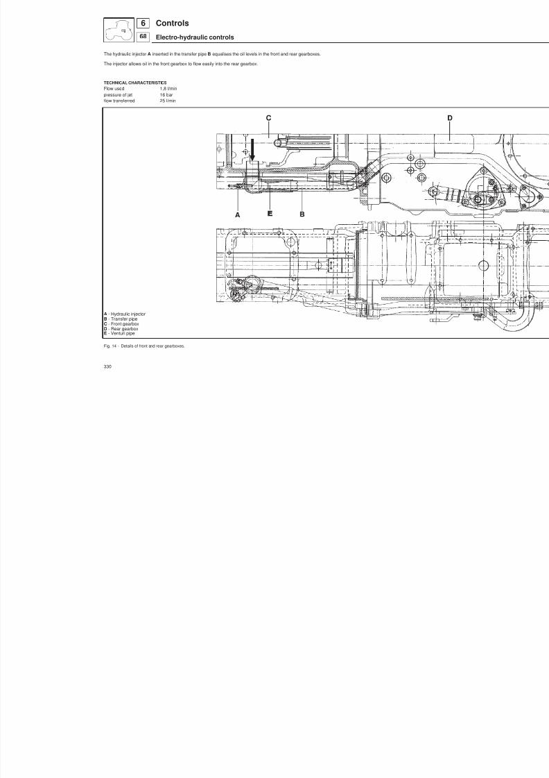
8/19/2019 Agrocompact f60 f70 f80 f90 Repair manual
http://slidepdf.com/reader/full/agrocompact-f60-f70-f80-f90-repair-manual 330/519
The hydraulic injector A inserted in the transfer pipe B equalises the oil levels in the front and rear gearboxes.
The injector allows oil in the front gearbox to flow easily into the rear gearbox.
TECHNICAL CHARACTERISTICSFlow used 1,8 l/min
pressure of jet 16 barflow transferred 25 l/min
A - Hydraulic injectorB - Transfer pipeC - Front gearboxD - Rear gearboxE - Venturi pipe
Fig. 14 - Details of front and rear gearboxes.
330
Controls
Electro-hydraulic controls
668
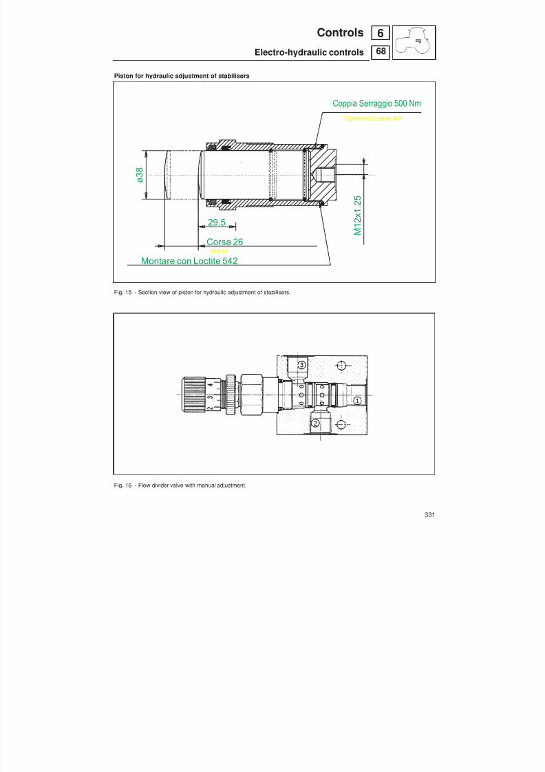
8/19/2019 Agrocompact f60 f70 f80 f90 Repair manual
http://slidepdf.com/reader/full/agrocompact-f60-f70-f80-f90-repair-manual 331/519
Piston for hydraulic adjustment of stabilisers
Fig. 15 - Section view of piston for hydraulic adjustment of stabilisers.
Fig. 16 - Flow divider valve with manual adjustment.
331
68
6Controls
Electro-hydraulic controls
Montare con Loctite 542
Coppia Serraggio 500 NmTightening torque Nm
ø 3 8
29.5 M 1 2 x 1
. 2 5
Stroke
Corsa 26

8/19/2019 Agrocompact f60 f70 f80 f90 Repair manual
http://slidepdf.com/reader/full/agrocompact-f60-f70-f80-f90-repair-manual 332/519
Adjustment of front and rear differential lock controlTurn fork A and lock nut B to preload spring C, so as to obtain a distance X allowing contact with piston E (with spring Dattached) when the piston is positioned flush with surface F (on version with electrohydrauliccontrols) or protrudes 18.5mm (on version with mechanical controls). Also checkthat the shoes of the fork do not rub against thesides of the enga -gement sleeve.For adjustment of engagement sleeve, see chapter on front-wheel drive.
Fig. 17 - Front and rear differential lock control.
332
68
6 Controls
Electro-hydraulic controls
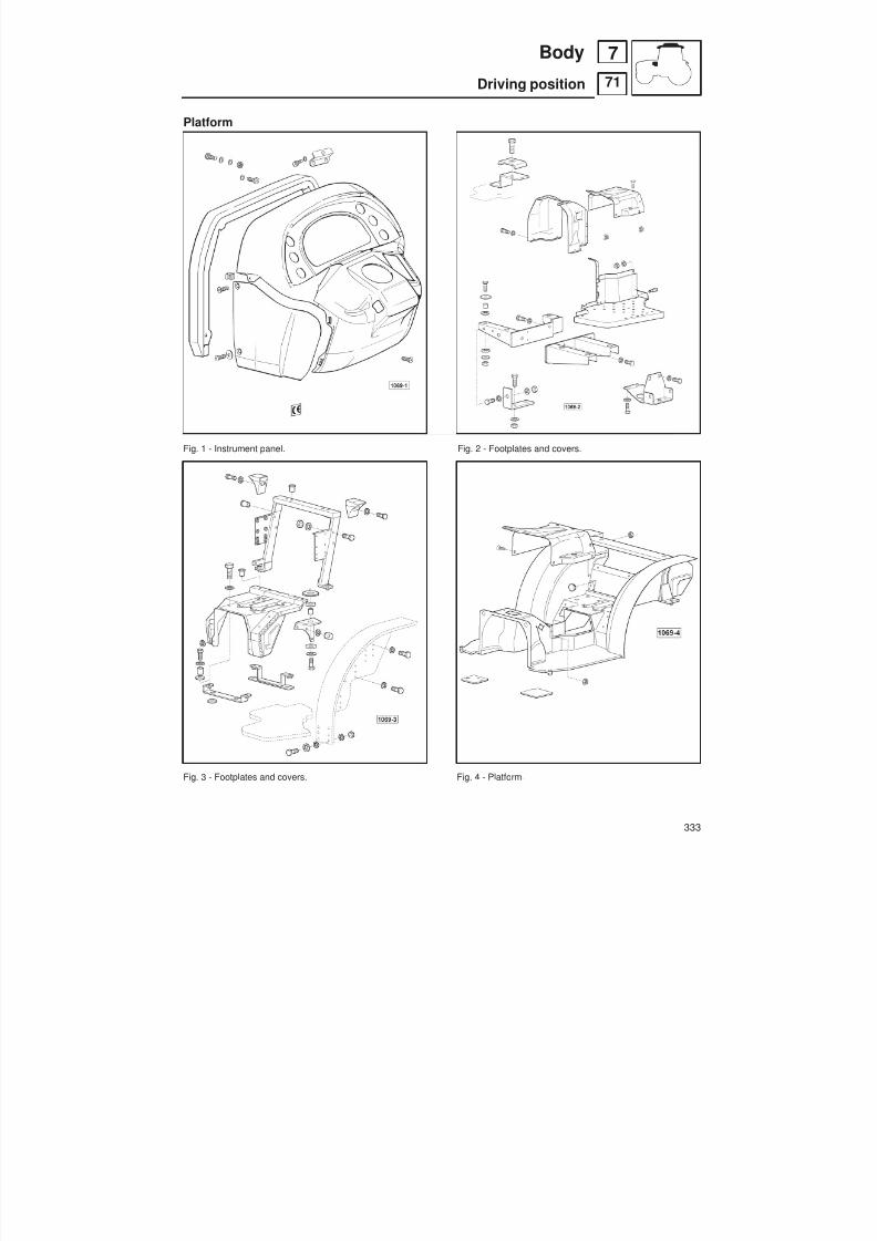
8/19/2019 Agrocompact f60 f70 f80 f90 Repair manual
http://slidepdf.com/reader/full/agrocompact-f60-f70-f80-f90-repair-manual 333/519
Platform
Fig. 1 - Instrument panel. Fig. 2 - Footplates and covers.
Fig. 3 - Footplates and covers. Fig. 4 - Platform.
333
71
7Body
Driving position

8/19/2019 Agrocompact f60 f70 f80 f90 Repair manual
http://slidepdf.com/reader/full/agrocompact-f60-f70-f80-f90-repair-manual 334/519
Fig. 5 - Rear mudguards. Fig. 6 - One-piece cab.
Fig. 7 - Glass and seals. Fig. 8 - Glass and seals.
334
71
7 Body
Driving position

8/19/2019 Agrocompact f60 f70 f80 f90 Repair manual
http://slidepdf.com/reader/full/agrocompact-f60-f70-f80-f90-repair-manual 335/519
Fig. 9 - Interior trim panels. Fig. 10 - Interior trim panels.
Fig. 11 - Windscreen wiper. Fig. 12 - Ventilation and air conditioning.
335
71
7Body
Driving position
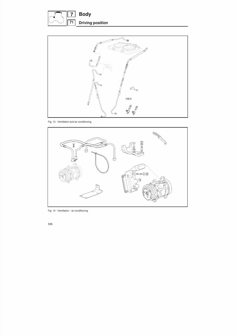
8/19/2019 Agrocompact f60 f70 f80 f90 Repair manual
http://slidepdf.com/reader/full/agrocompact-f60-f70-f80-f90-repair-manual 336/519
Fig. 13 - Ventilation and air conditioning.
Fig. 14 - Ventilation - air conditioning
336
71
7 Body
Driving position
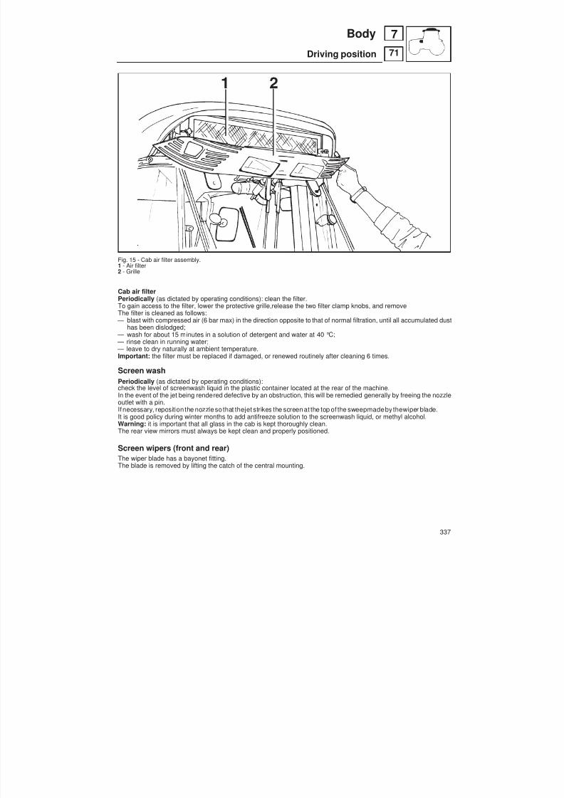
8/19/2019 Agrocompact f60 f70 f80 f90 Repair manual
http://slidepdf.com/reader/full/agrocompact-f60-f70-f80-f90-repair-manual 337/519
Fig. 15 - Cab air filter assembly.1 - Air filter2 - Grille
Cab air filterPeriodically (as dictated by operating conditions): clean the filter.To gain access to the filter, lower the protective grille,release the two filter clamp knobs, and removeThe filter is cleaned as follows:
— blast with compressed air (6 bar max) in the direction opposite to that of normal filtration, until all accumulated dusthas been dislodged;
— wash for about 15 minutes in a solution of detergent and water at 40 °C; — rinse clean in running water; — leave to dry naturally at ambient temperature.Important: the filter must be replaced if damaged, or renewed routinely after cleaning 6 times.
Screen washPeriodically (as dictated by operating conditions):check the level of screenwash liquid in the plastic container located at the rear of the machine.In the event of the jet being rendered defective by an obstruction, this will be remedied generally by freeing the nozzleoutlet with a pin.Ifnecessary, reposition the nozzle so that thejet strikes the screen at the top of the sweepmadeby thewiper blade.It is good policy during winter months to add antifreeze solution to the screenwash liquid, or methyl alcohol.Warning: it is important that all glass in the cab is kept thoroughly clean.The rear view mirrors must always be kept clean and properly positioned.
Screen wipers (front and rear)The wiper blade has a bayonet fitting.The blade is removed by lifting the catch of the central mounting.
337
71
7Body
Driving position

8/19/2019 Agrocompact f60 f70 f80 f90 Repair manual
http://slidepdf.com/reader/full/agrocompact-f60-f70-f80-f90-repair-manual 338/519
Remove cab.
Fig. 16 - Position the cab on suitable supportsand proceed with the operations on the tractor.
Breakage of the top hood releasecable
Fig. 17 - Component of the top hood release me -chanism.
WARNING: during the cab hoisting operation, check carefully thatall the parts have been disconnected and that the cab disengagesfrom the tractor.
IMPORTANT: If the fuel tank is also to be removed, disconnectthe flexible pipe from the metal leak-off pipe from the injectionpump.
To open the hood, insert a screwdriver between the hood and thegrille to operate the hood catch.
Push the screwdriver to the left (relative to the driving position) torelease the hood.
338
71
7 Body
Driving position

8/19/2019 Agrocompact f60 f70 f80 f90 Repair manual
http://slidepdf.com/reader/full/agrocompact-f60-f70-f80-f90-repair-manual 339/519
VentilationThe ventilation unit is housed in the cab ceiling.
To switch it on and adjust it, turn the electrical fan switch to the desired speed.The cabbecomes slightlypressurized when theventilationsystem is in operation, so that fresh aircanenteronly bywayof the filter installed in the rear section of the cab roof.The fan switch can be operated only after the ignition key is inserted.
The air flow can be regulated and directed by suitably positioning the air diffusers. Air can be taken in fresh from outside or recirculated from within the cab by way of the relative side inlets.
Recirculation inlets fully closed : air is taken in entirely from outside the cab through the rear grille and filte-red through a paper element positioned behind the grille.
Either fully or partially open air recirculating grille: now the air is recirculated inside the cab.
N.B. - It is very important that the air diffusers never be completely closed so as to allow for a steady air flow.To obtain a greater pressurization inside the cab, it is necessary to take the air from the outside, therefore the inside air recirculating grille should be fully closed.
Climate control system
A - Condenser
B - Control switches
C - Water radiator
D - Defroster
E - Ventilation unit
Heating SystemThe heater is switched on and adjusted by rotating the control knob at the roof console, then switching on the blower and setting the selector at the preferred speed .To warm the cab up quickly, the knob should be rotated fully clockwise and the blower set to speed III.The screen is demisted or defrosted by air directed through a slot vent.For defrost or fast demist, all other vents should be closed off.
IMPORTANT: ventilation is provided by a single blower unit serving both the heating system and the air-conditioningsystem. After reaching the desired temperature adjust the system to suit your needs.
N.B. - For ideal system operation, the engine must run at 1600 r.p.m.
WARNING: Before starting theengine, make sure thesystem is off (by turning off theventilationfan) so as not to overlo -ad the battery.
After using the system at full power for a long period of time, never turn it off suddenly but let it first idle for about 20 se -conds.
339
86
8Systems
Air conditioning

8/19/2019 Agrocompact f60 f70 f80 f90 Repair manual
http://slidepdf.com/reader/full/agrocompact-f60-f70-f80-f90-repair-manual 340/519
System configurationThe heating system consist of two units:
1 - Electric heater 3 (3 fig. 1) and blower unit (4 fig. 1) installed behind roof console.2 - Power supplyng set, consisting of an auxiliary alternator (1 fig.1) located front of the engine and driven by a belt di -rectly linked to the engine pulley.
If the air does not comeout from the diffusers right away as soonas the systemis started, turn off immediately and iden -tify the fault.
N.B. Never turn on the heating system when working in dusty environments.
In the event of the system failing to operate, check the fuse in the roof terminal box.
Fig. 1 - Configuration of ventilation and heating unit.
1 - Compressor (For air-cooled engine)2 - Engine coolant manifold (For water-cooled engine)3 - 3 speed fan4 - Heater5 - Evaporator6 - Ventilator7 - Dehydrating filter8 - Condenser9 - Air filter10- Recirculation inlets11- Pivotable air diffusers
340
86
8 Systems
Air conditioning
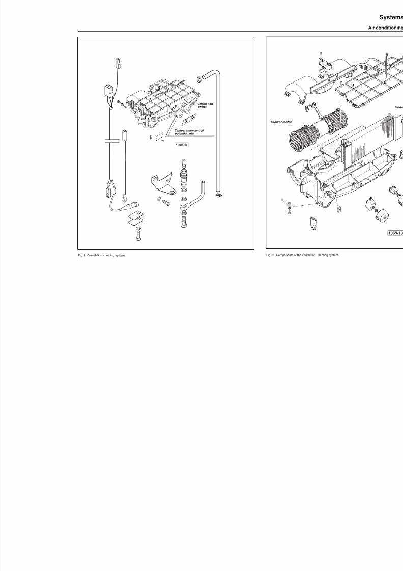
8/19/2019 Agrocompact f60 f70 f80 f90 Repair manual
http://slidepdf.com/reader/full/agrocompact-f60-f70-f80-f90-repair-manual 341/519
Ventilationswitch
Temperature control potentiometer
Fig. 2 - Ventilation - heatin g system.
Blower motor
Fig. 3 - Components of the ventilation - heating system.
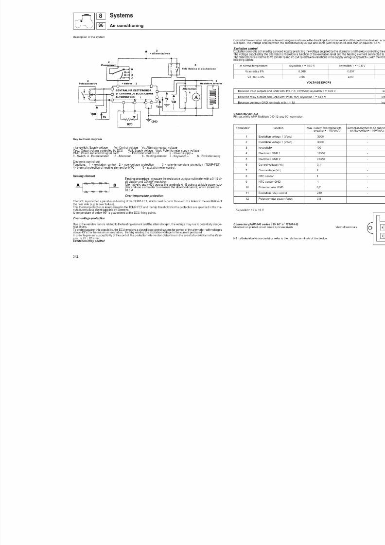
8/19/2019 Agrocompact f60 f70 f80 f90 Repair manual
http://slidepdf.com/reader/full/agrocompact-f60-f70-f80-f90-repair-manual 342/519

8/19/2019 Agrocompact f60 f70 f80 f90 Repair manual
http://slidepdf.com/reader/full/agrocompact-f60-f70-f80-f90-repair-manual 343/519
Air conditioning unit for cabsThe air conditioning system will operate only with engine running and the 3-speed electric fan unit switched on.
Technical specifications
type of refrigerant R 134 ainlet circuit pressure (*): high bar 2,5- normal bar 0,8 ÷ 2,5- low bar 0,8delivery circuit pressure bar see page 350quantity of refrigerant in circuit g 950quantity of oil cc 110type of oil Suniso SP20minimum pressure switch setting bar 2maximum pressure switch setting bar 27electric fan pressure switch setting close at 15 bar - open at 11 bar tightening torque for pipeline fittings kgm (Nm) 6 (58)
(*)Pressure is influenced by ambient temperature; in normal operating conditions, with a temperatureof 27 °C,pressu -re in the delivery circuit will be 12 bar.
Pressure in the same system will register at around 16 bar with an ambient temperature of 38 °C.
1 - Electromagnetic coupling2 - Compressor3 - Condenser4 - Fan5 - Filter6 - Sight glass7 - Minimum pressure switch8 - Electric fan control
pressure switch9 - Maximum pressure switch
10 - Expansion valve11 - Evaporator12 - Bulb13 - Potentiometer
Fig. 4 - Diagram showing operation of air conditioning system.
343
86
8Systems
Air conditioning

8/19/2019 Agrocompact f60 f70 f80 f90 Repair manual
http://slidepdf.com/reader/full/agrocompact-f60-f70-f80-f90-repair-manual 344/519
Operation and maintenance of the air-conditioning system
Air-conditioning processThecooler is provided with a three-speed fanwhich aspirates theair from thecab interior thereafter forcing it across theradiant block, thus making it cool down.
The heat exchange occurring between the gaseous coolant and the air lapping the walls of the cooler radiant block re -sults in air cooling.
Theconditioned airundergoes a humidification process, as the lowtemperatureinside thecoolercausesa great deal of condensate to deposit on theexternal walls of thecooler. This condensate is subsequently conveyed under liquid stateoutside the cab through a special drainage system.
The coolant at the cooler exit is still under gaseous state and has a temperature of 5 to 10°C, in spite of the thermal ex -change that has taken place, and then it is aspirated by the compressor again.
How to operate the system
Before starting the air-conditioning system set the electric fan onto the desired speed. If the electric fan is switched off,the conditioning system will not start.
Theair-conditioningsystemis turnedon by progressively rotating thecontrol potentiometer clockwise, which is locatedin the front top section of the cab compartment. Rotate it anticlockwise to turn the system off.
Warning: Before starting the engine, always make sure the air-conditioning system is switched off so that the battery
will not be overloaded.
When the air-conditioning system is operating, the pivotable air diffusers should never be completely closed.To obtain a quick cab environment cooling the following is recommended:
— fully open the air recirculation grating and the pivotable air diffusers;
— turn first the fan control and then the potentiometer control all the way out;
— open the doors a few seconds so as to let the hot air out of the cab compartment if the tractor has stood under the sun radiation for a long period;
— adjust the system according to personal preference when the desired temperature has been attained.
Checking the air-conditioning system charge
System fully charged(refrigerant entirely in liquid state)System fully discharged(refrigerant entirely in gaseous state)
System not fully chargedRefrigerant in part gaseous and part liquid state
Sight glass clear
Sight glass cloudy
(Bubbles or foam visible)
344
86
8 Systems
Air conditioning

8/19/2019 Agrocompact f60 f70 f80 f90 Repair manual
http://slidepdf.com/reader/full/agrocompact-f60-f70-f80-f90-repair-manual 345/519
Switching on the air conditioning
Electromagnetic coupling
Pressure switches
Expansion valve
Temperature sensor
The system is activated by way of the 3 spe -ed electric fan switch.
Once the potentiometer is moved beyondthe initial contact, a voltage of 12 V is gene -rated between terminal B (red wire) and thebrown wire terminal of the potentiometer.
Engagement and disengagement is pilotedby the temperature control potentiometer,and by the pressure switch located at thedemoisturizing filter which cuts in respecti -vely at: 2 bar and 27 bar.
Pressure switch (positioned on demoisturi -zing filter)Comprises 3 switches:
— 1 controlling minimum pressure — 1 controlling maximum pressure — 1 controlling the electric fan of the con-
denser. The electric fan unit is interloc -kedto thepressureswitch, which is set:- to close the circuit at 15 bar - to open the circuit at 11 bar
Electric fan unit
By-pass the pressure switch (place jumpers across the two terminals of the pressure switch and the 2 leads of the fanunit).
If the fan operates: the pressure switch is defective
If the fan does not operate: a) check the fuse;b ) check the relay .
Tracing faults in the electric fan unit
Fault Causes Action
Fan does not start Defective pressure switch Replace pressure switch
Defective relay Replace relay
Defective electrical or mechanical Replace fan unit motorino difettosa
Relay (see electrical diagram)Place a jumper across terminals 30 and 87a ; if the fan comes into operation, the relay needs to be replaced.
Water dripping from the points at which condensate drain lines are connected to the condi -
tioning unitThe problem can be overcome by loosening the clip that fastens the drain line to the cab upright and pulling the tubedownwards, so that the water can run away freely.
345
86
8Systems
Air conditioning

8/19/2019 Agrocompact f60 f70 f80 f90 Repair manual
http://slidepdf.com/reader/full/agrocompact-f60-f70-f80-f90-repair-manual 346/519
Fig. 5 - Compressor, air conditioning system.
Fig. 6 - Demoisturizing filter, air conditioning system.
346
86
8 Systems
Air conditioning

8/19/2019 Agrocompact f60 f70 f80 f90 Repair manual
http://slidepdf.com/reader/full/agrocompact-f60-f70-f80-f90-repair-manual 347/519
Checking systemCheck belt tension: under finger pressure applied to themidpointbetween the twopulleys, belt shouldnot deflect more
than 8 to 10 mm maximally.
Always keep condenser fins duly clean.
Cleaningshould becarried out by a water or air jet (be careful not tobendthe fins, use the special combing tool to straig -hten them again).
Ascertain the compressor is firmly secured to tractor and the pulleys are properly aligned.
Warning: When removing the strainer or the air-conditioning unit it is required to plug the inlet and the outlet pipes atonce, this is to prevent both dust and moisture from entering.
Even a few minutes’ exposure to the environmental humidity makes it necessary to replace the filter.
System safety elementsMinimum pressure switch (7 Fig. 4) .Switches the system off when a failure causes the pressure to drop below 2 bar within the high pressure circuit.
Maximum pressure switch (9 Fig. 4).Switches the system off when pressure exceeds 27 bar inside the circuit as a result of an excessive setting or a failure(high pressure area).
Condenser fan control pressure switch (8 Fig. 4)Switches the condenser fan on when coolant attains the same pressure of the switch setting pressure.Note: The above three safety devices are grouped inside the thermostatic bulb located on the dehydrator filter. (Fig. 6page 346).
Temperature regulation
Temperature regulation is obtainedthrough the potentiometer, which automatically regulates the temperature of the air flow from the radiator according to the environmental temperature, through a combined action with the fan.
A pressure switch located on the electric circuit opens and closes the electric circuit of the compressor electromagneticcouplingas a consequenceof thepotentiometeroperation. When thecircuit is open thepulley will be idling, on theother hand, when the circuit is closed, this will operate integrally with the compressor shaft.
347
86
8Systems
Air conditioning

8/19/2019 Agrocompact f60 f70 f80 f90 Repair manual
http://slidepdf.com/reader/full/agrocompact-f60-f70-f80-f90-repair-manual 348/519
Charging the systemwith recharging station p/n 5.9030.508.6
1 - High pressure gauge2 - Low pressure gauge3 - Low pressure valve4 - Vacuum pump valve5 - Metering pipeline valve6 - Recharge pipeline valve7 - Metering pipeline8 - Vacuum pump pipeline9 - Low pressure circuit recharge pipeline
(blue)10 - High pressure circuit recharge pipeline
(red)11 - Vacuum pump12 - Electric switch13 - Metering gauge14 - Air bleed valves15 - Metering unit16 - Electrical power supply17 - Compressor18 - Refrigerant bottle19 - Electric leak detector20 - Electric heater element for refrigerant
Fig. 7 - Charging station for air conditioning circuit.
Filling the metering unitConnect the refrigerant bottle to the metering unit by means of the high or low pressure hose (9 - 10 Fig. 7).Make certain that the valve (5 Fig. 7) is securely shut, then open the valve of the bottle. As the refrigerant flows into the metering unit, open and shut the air bleed valve (14, Fig. 7) intermittently.Read thevaluegivenby thehandof themetering unit pressure gauge (13, Fig. 7) and positionthe valueagainst theindi -cator.Once 950 grams of refrigerant have been transferred into the metering unit, close the valve of the bottle and detach thehose.
Refilling the system with oilConnect the highpressurehose (9, Fig. 7)of the rechargestation byway of the smaller diametervalve A (Fig.8) positionedon the pipeline connecting with fitting D (Fig. 5) at the compressor (mounted in the engine compartment), and the low
pressure hose (10, Fig. 7) of the station by way of the larger diameter valve B (Fig. 8) positioned on thepipeline connec -ted with fitting S (Fig. 5) at the compressor; then activate the pump for 30 minutes approx to establish a vacuum in thecircuit.The valves (3 - 4 - 5 - 6, Fig. 7) must remain open during this operation.
348
86
8 systems
air conditioning
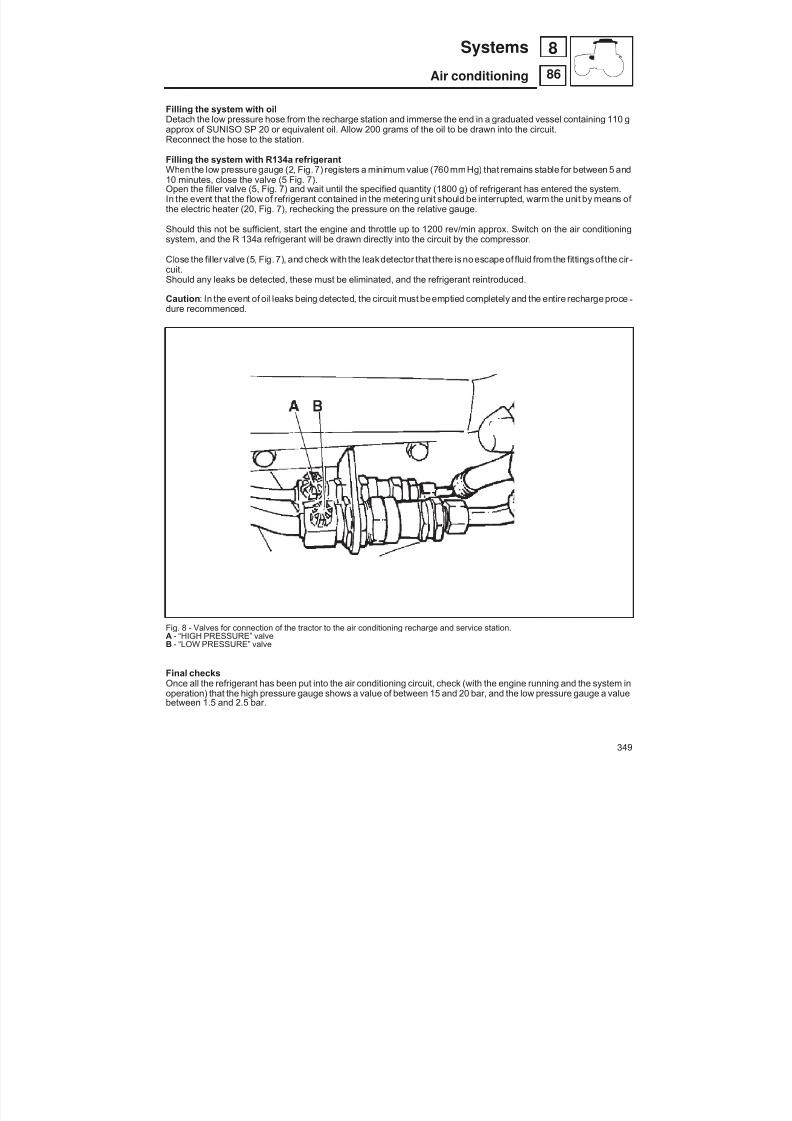
8/19/2019 Agrocompact f60 f70 f80 f90 Repair manual
http://slidepdf.com/reader/full/agrocompact-f60-f70-f80-f90-repair-manual 349/519
Filling the system with oilDetach the low pressure hose from the recharge station and immerse the end in a graduated vessel containing 110 gapprox of SUNISO SP 20 or equivalent oil. Allow 200 grams of the oil to be drawn into the circuit.Reconnect the hose to the station.
Filling the system with R134a refrigerantWhen the low pressure gauge (2, Fig. 7) registers a minimum value (760 mmHg) that remains stable for between 5 and10 minutes, close the valve (5 Fig. 7).Open the filler valve (5, Fig. 7) and wait until the specified quantity (1800 g) of refrigerant has entered the system.In the event that the flow of refrigerant contained in the metering unit should be interrupted, warm the unit by means of the electric heater (20, Fig. 7), rechecking the pressure on the relative gauge.
Should this not be sufficient, start the engine and throttle up to 1200 rev/min approx. Switch on the air conditioningsystem, and the R 134a refrigerant will be drawn directly into the circuit by the compressor.
Close the filler valve (5, Fig. 7), and check with the leakdetector that there is noescapeof fluid fromthe fittings of the cir -
cuit.Should any leaks be detected, these must be eliminated, and the refrigerant reintroduced.
Caution : In the event of oil leaks being detected, the circuit must beemptied completely and the entire recharge proce -dure recommenced.
Fig. 8 - Valves for connection of the tractor to the air conditioning recharge and service station.A - “HIGH PRESSURE” valveB - “LOW PRESSURE” valve
Final checksOnce all the refrigerant has been put into the air conditioning circuit, check (with the engine running and the system inoperation) that the high pressure gauge shows a value of between 15 and 20 bar, and the low pressure gauge a valuebetween 1.5 and 2.5 bar.
349
86
8Systems
Air conditioning

8/19/2019 Agrocompact f60 f70 f80 f90 Repair manual
http://slidepdf.com/reader/full/agrocompact-f60-f70-f80-f90-repair-manual 350/519
VERIFYING OPERATION OF THE SYSTEM AFTER RECHARGINGThe system can be regarded as performing to its full capabilites when the delivery pressure gauge shows the following
values: Ambient temperature °C Delivery circuit pressure
27 12 bar 32 14 bar 35 15 bar 38 17 bar 40 18 bar 43 20 bar
The temperature values indicated are those likely to be encountered in the course of a typical twelve month period.
Havingestablished that the systemis operating correctly, detach the high and lower pressure hoses of the station fromthe tractor and check again with the leak detector that there is no escape of fluid from any part of the system.
CAUTION : use onlyR 134arefrigerant asindicated onthe Connecting the tractor tothe air conditioning systemrechargeR data plate attached to the compressor of the air conditioning and service station.system.
Directions for tightening air conditioning system pipeline fittings. All fittings have an internal seal. Screw the two parts of the fitting together by hand until the nut is finger tight, then hol -ding the one part steadywitha fixed wrench, apply a torquewrench to the nut and tighten to the value indicated in the ta -ble.
Type Thread Tightening torque
6 5/8” - 18 UNF 13,6 ÷ 20,3 Nm (1,4 ÷ 2,1 kgm)
7 3/4” - 16 UNF 33,5 ÷ 40,0 Nm (3,3 ÷ 4,0 kgm)
8 7/8” - 16 UNF 35,5 ÷ 42,0 Nm (3,6 ÷ 4,3 kgm)
9 1 1/16” - 16 UNF 40,3 ÷ 47,5 Nm (4.1 ÷ 4,8 kgm)
350
86
8 Systems
Air conditioning

8/19/2019 Agrocompact f60 f70 f80 f90 Repair manual
http://slidepdf.com/reader/full/agrocompact-f60-f70-f80-f90-repair-manual 351/519
Fig. 9 - Control switches1 - Heating control.2 - Air conditioning control.3 - Ventilation control.
Fig. 10 - Receiver-drier located in cab roof. Fig. 11 - Air conditioning unit.1 - Level sight glass.

8/19/2019 Agrocompact f60 f70 f80 f90 Repair manual
http://slidepdf.com/reader/full/agrocompact-f60-f70-f80-f90-repair-manual 352/519
R 2
. 5
R 4 B 0
. 5
C 4
MM
1
2
3
CTF
RV
0
N 4
R 4
M 2.5
LR 1.5
COMPONENTS LIST
ELECTRICAL DIAGRAM FOR HEATING AND AIR CONDITIONING SYSTEM
M - BLOWER FANRV - FAN SPEED RESISTORC - FAN SPEED CONTROL SWITCH
RC - AIR CONDITIONING RELAYF - POWER FUSET - AIR CONDITIONING PRESSURE SWITCHCO - COMPRESSORS - DEFROSTING THERMOSTATB - POWER SUPPLY CONNECTOR A - CLIMATE CONTROL CONNECTOR
352
Systems
Air conditioning
886
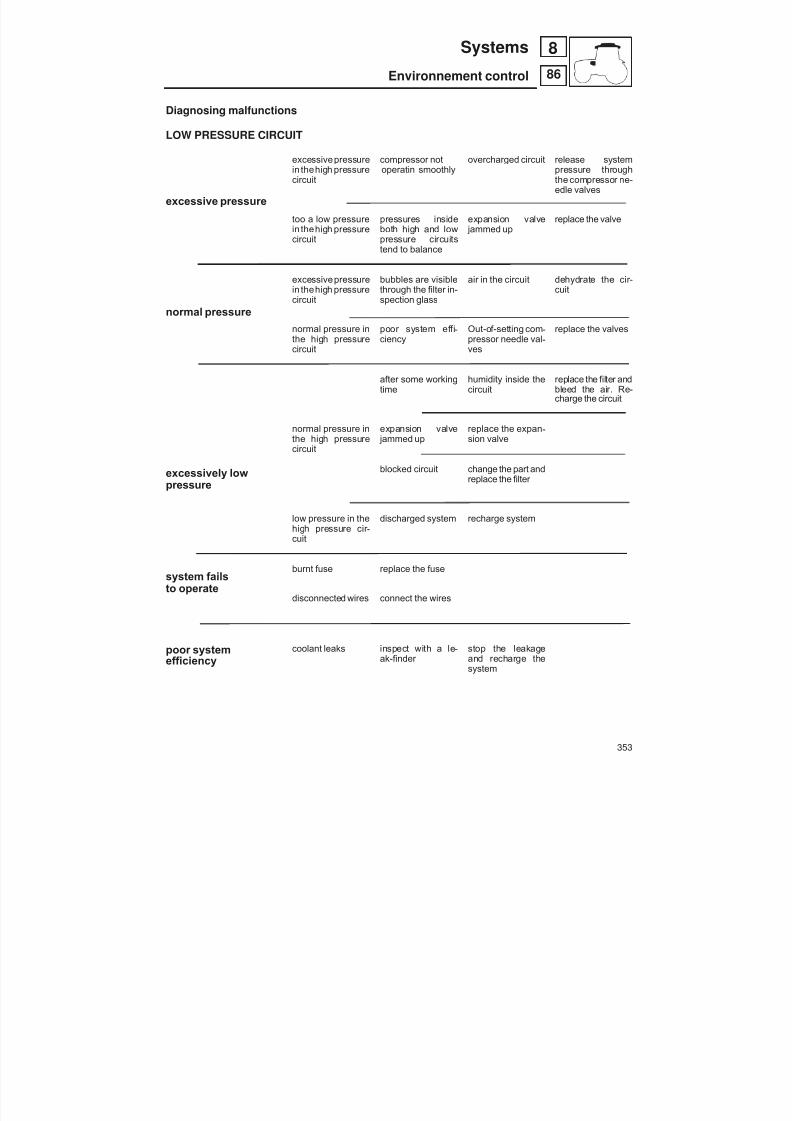
8/19/2019 Agrocompact f60 f70 f80 f90 Repair manual
http://slidepdf.com/reader/full/agrocompact-f60-f70-f80-f90-repair-manual 353/519
Diagnosing malfunctions
LOW PRESSURE CIRCUIT
excessive pressure
normal pressure
excessively lowpressure
system failsto operate
poor systemefficiency
excessivepressurein thehigh pressurecircuit
too a low pressurein thehigh pressurecircuit
excessivepressurein thehigh pressurecircuit
normal pressure inthe high pressurecircuit
normal pressure inthe high pressurecircuit
low pressure in thehigh pressure cir -cuit
burnt fuse
disconnected wires
coolant leaks
compressor notoperatin smoothly
pressures insideboth high and lowpressure circuitstend to balance
bubbles are visiblethrough the filter in -spection glass
poor system effi -ciency
after some workingtime
expansion valve jammed up
blocked circuit
discharged system
replace the fuse
connect the wires
inspect with a le -ak-finder
overcharged circuit
expansion valve jammed up
air in the circuit
Out-of-setting com -pressor needle val -ves
humidity inside thecircuit
replace the expan -sion valve
change the part andreplace the filter
recharge system
stop the leakageand recharge thesystem
release systempressure throughthe compressor ne -edle valves
replace the valve
dehydrate the cir -cuit
replace the valves
replace the filter andbleed the air. Re -charge the circuit
353
86
8Systems
Environnement control

8/19/2019 Agrocompact f60 f70 f80 f90 Repair manual
http://slidepdf.com/reader/full/agrocompact-f60-f70-f80-f90-repair-manual 354/519
Hydraulic system
KEY TO FIGURE 1:
1 - Delivery line pressure test point2 - Hydrostatic steering - maximum hydrostatic steering pressure (see instructions on p. 290).3 - 4WD steering cylinder pressure test point4 - 2WD steering cylinder pressure test point5 - Gearbox oil cooler6 - Electro-hydraulic control unit (see instructions on p. 196)7 - Hydraulic power unit pressure test point (see instructions on p. 263)8 - Lubrication oil pressure test point9 - H-M-L
10 - Hydraulic unloader for equalising oil level in gearboxes11 - Gearbox lubrication12 - Rear P.T.O. (see instructions on p. 196)13 - Diff. lock hydraulic actuators14 - 4WD engagement hydraulic actuator15 - Trailer braking hydraulic control valve16 - Pressure test point for trailer braking hydraulic control valve17 - 8-way auxiliary control valve (see instructions on pages 362-376)18 - Pressure relief valve oil pressure test point19 - Kick-out oil pressure test point (see instructions on page 365)20 - Hydraulic ways oil pressure test point21 - Connected implement22 - Rear lift23 - Front lift antishock valve and accumulator24 - Implement coupled to rear lift25 - Lifting cylinder26 - Rear lift antishock valve27 - Front lift (see instruction on p. 362)28 - Lifting cylinder pressure test point29 - Front lift antishock valve30 - Shut-off valve for oil supply to front lift
31 - Supplementary hydraulic control valves32 - Operating pressure test point for supplementary hydraulic control valve33 - Pressure test point for kick-out of supplementary hydraulic control valve34 - Implement connected to supplementary hydraulic control valve35 - Pressure relief valve setting pressure test point36 - Supplementary flow divider valve37 - Hydraulic power unit for 3-point linkage with hydraulic adjustments38 - Rh lift rod with hydraulic adjustment39 - Rh stabiliser40 - Lh stabiliser41 - Free oil return line on right-hand side of tractor (for hydraulic motors)42 - Hydraulic ways on right-hand side43 - Free oil return line on rear of tractor (for hydraulic motors)44 - Front P.T.O. control valve (see instructions on p. 281).
354
82
8 Systems
Hydraulic system

8/19/2019 Agrocompact f60 f70 f80 f90 Repair manual
http://slidepdf.com/reader/full/agrocompact-f60-f70-f80-f90-repair-manual 355/519
Fig. 1 - Points provided for measurement of oil pressures in the tractor’s hydraulic system (see references on page 354).
A
P T
A
P T
T
railer
brake
T
ractor
brake
701 Bar
190 Bar T
E
P
A AB B
1
0 0
2 2
1
1
0
N
H M L
P T
A A
I n n
.
D i s
.
Front
Dif
f.look
Rear
D i s
.
I n n
.
4 Wd
TP
7 0 0
c c
A
B
PT
V max V max V max13.9 cm14.7 cm11.6 cm 3 3 3
6/20 L/min.
11+11 cm27+27 L/min.
3
ø 1
Rh
side
Rh
side
Free
return
Rh
side
0.35
bar
P
Y
Rh Lf Rh
190 bar P-Ecc.
P-Reg.
AB B
A
B
Rear
free
return
F.to A2
L R
T P
5 bar 16 bar
Rapp. 1/1.0732 (44/41)
A
P T
11 bar
8 Bar
OSPC 80 OR
100 Bar 2 WD
150 Bar 4 WD
27 L/min.
150 Micr.
3 2 c c
ø 1.1
Main
shaf
t
Sec.
shaf
t
N.giri/min.pompe:2522
11 cm 3
x
15 Micr.
Freno inser.=13 bar,disinser.=5 bar
T I R A N T E D X
S T A B I L I Z Z
. D X
100 Bar
ø1.8
c o n v a
l v . d i
b l o c c o
P
S T A B I L I Z Z
. S X
ø0.7 ø0.7
TIROSPINTA
6 Bar
N
T
T P
A
P T
A
A A
PT
T PP Tø1.2
16 bar
150 bar 100 bar
190 bar
150 bar
5 bar
CENTRALINA COMANDI ELETROIDRAULICI
AGROSHIFT
PTO
16 bar
GUIDA IDROSTATICA
DISTRIBUTORI IDRAULICISUPPLEMENTARI
DISTRIBUTORE IDRAULICOPER LA FRENATURA DEL RIMORCHIO
CENTRALINA IDRAULICA DI COMANDODELL’ATTACCO A 3 PUNTI CONREGOLAZIONIIDRAULICHE
SOLLEVATORE ANTERIORE
SOLLEVATORPOSTERIORE
DISTRIBUTORE IDRAU
ATTREZZO COLLEGATO ATTREZ
Pressione dii esercizio Pressione dii esercizio
Pressione Max valvola di sicurezza
Sollevatore anteriorecon attrezzo collegato
Pressione di esercizio
190 bar
190 bar
1
2
4
5
6
7
8
10
1112
13 14
15
16
20
22
23
17
16 bar VALVOPTO an
27
28
29
30
31
32 33
34
35
3
9
36
38
3940
41 42 43
37
PTOH-M-L

8/19/2019 Agrocompact f60 f70 f80 f90 Repair manual
http://slidepdf.com/reader/full/agrocompact-f60-f70-f80-f90-repair-manual 356/519
Oil filtersThetractoris equipped with 15 micronfilter installedon thedeliverylinefrom thehydraulic pump to thehydrostatic steeringsystem. This filter is located on the right-hand side of the tractor and has an interchangeable cartridge.This filter cartridge must be renewed:after the first 50 operating hours;after the first 150 operating hours;and every 300 operating hours thereafter.
Inany case,the filtercartridgemust berenewedwhenthe "filter clogging"warninglight onthe console stayson afterthe en -gine has reached normal operating temperature.It is, however, perfectly normal for the light to stay on for a few minutes after starting the engine.
The tractor is equipped with a second filter with a filtration capacity of 160 microns. This second filter is located on the firstsection of the oil suction line on the right-hand side of the tractor.This filter cartridge is to be renewed after the first 150 operating hours and thereafter every 1200 operating hours .To renew the suction line filter cartridge, loosen the two straps securing the filter.Torenewthefilter cartridgeon thehydrostatic steeringdeliveryline, simplyunscrewtheold cartridgeandfit a newone.
The filter clogging pressure switch is set to 2.4 bar; if the pressure switch loses its setting it must be replaced with another switchwiththesamecharacteristics.Checkthatthe calibrationsettingof 2.4baris stamped onthe body ofthe newswitch.
IMPORTANT - If the "filter clogging" warning light comes on during operation of the tractor, replace the filters.
Fig. 2 - Component parts of the hydraulic pump assembly
A - Snap-ring H - Bearing
B - Seal ring I - BushesC - Cover L - Driver gearD - Gasket M - Pump caseE - Gasket N - GasketF - Gasket O - Driver gearG - Feather key P - Cover
Hydraulic pumpsThe hydraulic pumps require no servicing or adjustment even after a long period of operation, although the splines of thepump shaft must be inspected with care: there must be no signs of wear or damage.
Checking the relief valves of the hydraulic lift system
Using tool 5.9030.520.4, check that the circuit pressure relief valve incorporated into the auxiliary spool valves is set at 190bar and the system pressure shock valve at 210 bar.Remember that for the lift to function correctly, operating pressure in the circuit should not exceed 150 bar.The operating pressure can be measured by coupling a gauge to the oil pressure line between the directional control valveandthe lift;for machines withassistorcylinders, the gaugecan be coupled to the pressureline connectingwith theassistors.
Fig. 3 - Pump assembly cover. A - Cover. B - Pump case.C - Base.
356
Systems
Hydraulic system
882

8/19/2019 Agrocompact f60 f70 f80 f90 Repair manual
http://slidepdf.com/reader/full/agrocompact-f60-f70-f80-f90-repair-manual 357/519
Stripping the hydraulic pumpRemoval
The pump is secured to the tractor by 2 of the 4 bolts holding thepump assembly together. These two bolts are diagonally opposi -te. Having removed the pump from the vehicle, the componentsare freed by unscrewing the two remaining bolts which keep thecover A (see fig 3) clamped to the frame C and the pump body B;this done, remove the washers and then the cover.
Using a proper pointed tool removegasket E and then take the be -arings from their seats by pushing from insideoutwards and beingcareful the connecting pin neither be lost nor damaged.
Mark with a reference the position of the bearings with respect tothe pump case; then remove paying attention the connecting pinneither be lost nor damaged.
Block the pump case in a vice as shown in figure and then removesnap ring F .
Remove the seal ring.
WARNING - If pump bearings, pinions or casing are found to bedamagedor worn, these parts cannot be repaired because of their construction tolerances.
When performing checks, in thewarrantyperiod, because of an oilleakage or an excessive and irregular delivery pressure, only the
gaskets indicated in the spare parts lists can be replaced. After checking the pump for wear due to abrasion from impuritiesand for any other visible damage, when reassembling use, in anycase, a new set of gaskets.
It is also indispensable to mark each single part to reinstall cor -rectly.
B - Pump caseC - BaseD - BearingsG - GearsI - Screw
Fig. 5 - Pump disassembly.
D - BearingE - Gasket
Fig. 6 - Internal pump case parts.
C - HousingD - BearingG - GearH - Bush
Fig. 7 - Pump gears.
C - BaseF - Snap ring
Fig. 8 - Snap ring removal.
357
82
8Systems
Hydraulic system

8/19/2019 Agrocompact f60 f70 f80 f90 Repair manual
http://slidepdf.com/reader/full/agrocompact-f60-f70-f80-f90-repair-manual 358/519
A - Stop ringB - GasketC - Bearings
Fig. 9 - Inside seals.
A - Seal ring.
Fig. 10 - Seal ring.
Inspections and checks After removing all gaskets, both on the covers and in the pump ca -sing, carefully clean all parts using a proper solvent.Carefully dry all parts with compressed air; this is to avoid that anysolvent residuals may damage the gaskets on reassembly.Visually check the pump case internally and ascertain it is not da -maged.Check both pinions andbearings for wear, abrasiondue to foreignmatters or cavitation.
NOTE: Should any damage, wear or in any case a component re -placementbe required, with theexception of thegaskets, theenti -re pump must be replaced.WARNING: Do not press onto the stop ring to prevent any dama -ge.Use a dialgauge tomakesure the stop ringheight be 21 0 15
0 05, ,,
-+ mm,
otherwise replace taking care the new stop ring installed be mea -sured accordingly.If reading is above specification fit the new ring in reversed posi-tion and perform a grinding using a very fine emery cloth.
AssemblyBefore assembly all parts shall be oiled.Correctly position the gaskets in their seats paying particular atten -tion stop ring A and gasket B be correctly fitted into bearings C.Coat the cover inner side with a slight grease layer then apply topump case and tightening the four securing screws to the recom -mended torque.
WARNING: The securing screws should be tightened graduallymaking also sure that rotors are not hampered in their move -ments.
Tightening torquesPump cover securing screws:- M8 2 kgm (20 Nm)- M10 5 kgm (49 Nm)
Restore therecommended oil level and then bleed theair from thehydraulic circuit.
Fig. 11 - For tractors with flow control; fit the check valve observing the di-rection of the arrow in the figure.
358
82
8 Systems
Hydraulic system

8/19/2019 Agrocompact f60 f70 f80 f90 Repair manual
http://slidepdf.com/reader/full/agrocompact-f60-f70-f80-f90-repair-manual 359/519
Auxiliary hydraulic spool valves Auxiliary spool valves are used to control hydraulically operated external implements.The controls consist in 2 levers
for a 4-way valve, or 3 levers for a 6-way valve.The levers are located on the driver’s right hand side.
Auxiliary hydraulic spool valves:
Version 1: with 4 ways (2 double-acting ways convertible to single-acting and equipped with detent). Version 2: with 6 ways (2 double-acting ways convertible to single-acting and with kick-out; 2 double-actingways con-vertible to single-acting and with detent; 2 double-acting ways convertible to single-acting with float position).
Version 3: with 10 ways (version 2 + 4 ways in mid-position of tractor, 2 on left and 2 on right).
Furthermore, there is a special version for those users who require additional controls for a wider range of ap -plications.
Version 4: 12 ways (version 2 + 6-way control valve) located in the middle of the tractor on the right-hand side withelectro-hydraulically operated control valve.
6 ways connected to the control valve located at the rear of the tractor and operated by way of the levers mo -unted on the mudguard to the right of the driver (two double-acting 1-1 ways convertible to single-acting andwith kick-out, two double-acting 2-2 ways convertible to single-acting and with detent, two double-acting 3-3ways with float position).
2 ways controlled by rocker switch with float position (mid-mounted ways number 4-4 on right-hand side of trac -tor) connected to the electro-hydraulically controlled control valve located in the middle of the tractor onright-hand side.
4 ways controlled by joystick (mid-mounted ways number 6-6 on left-hand side of tractor and mid-mountedways number 5-5 on right-hand side of tractor) The joystick is equipped with a lock-release button; when thisbutton is released when the joystick is in the position with the yellow marker, Float position is obtained. Theways are connected to the electro-hydraulic control valve located in the middle of the tractor on the right-handside.
NB: with theauxiliary spool valve in use(unless a Flow Divider is incorporated), theoperation of thehydraulic lift systemremains inhibited (except in FLOAT position).
Important: the lever should be recentred to the neutral position as soon as the external actuator has reached its strokelimit, to ensure that thehydraulic circuit does not remainpressurizedany longer than strictly necessary; prolonged pres -sure will result ultimately in the hydraulic system being subjected to hazardous levels of stress. Auxiliary spool valves levers must always be in the neutral position when external services are not in use.
359
88
8Systems
Auxiliary systems

8/19/2019 Agrocompact f60 f70 f80 f90 Repair manual
http://slidepdf.com/reader/full/agrocompact-f60-f70-f80-f90-repair-manual 360/519
Fig. 1 - 4-way auxiliary control valves.A - Quick coupling for free dischargeB - Pressure relief valve.
360
88
8 Systems
Auxiliary systems
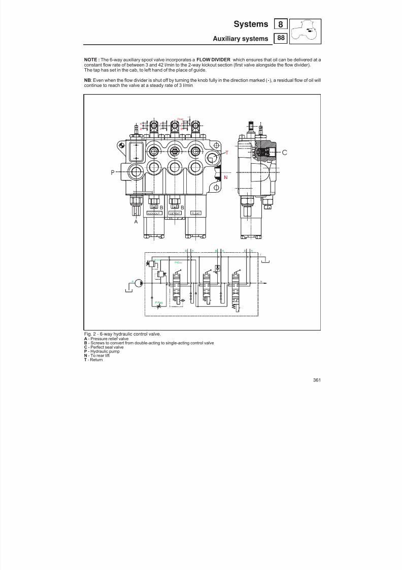
8/19/2019 Agrocompact f60 f70 f80 f90 Repair manual
http://slidepdf.com/reader/full/agrocompact-f60-f70-f80-f90-repair-manual 361/519
NOTE : The 6-way auxiliary spool valve incorporates a FLOW DIVIDER which ensures that oil can be delivered at aconstant flow rate of between 3 and 42 l/min to the 2-way kickout section (first valve alongside the flow divider).The tap has set in the cab, to left hand of the place of guide.
NB: Even when the flow divider is shut off by turning the knob fully in the direction marked ( -), a residual flow of oil willcontinue to reach the valve at a steady rate of 3 l/min.
Fig. 2 - 6-way hydraulic control valve.A - Pressure relief valveB - Screws to convert from double-acting to single-acting control valveC - Perfect seal valveP - Hydraulic pumpN - To rear liftT - Return
361
88
8Systems
Auxiliary systems
KICK-OUT FLOATDETENT.
190 bar P-Ecc.
P-Reg.
P
B AB A
T
N
B A
P
B B
N
T
A
A
B
A
B
Float
A
B 5
5
5
5
5
5
4
C

8/19/2019 Agrocompact f60 f70 f80 f90 Repair manual
http://slidepdf.com/reader/full/agrocompact-f60-f70-f80-f90-repair-manual 362/519
Fig. 4 - Checking the operating pressure of auxi -liary spool valves.A - Quick couplerB - Implement oil lineC - Tee
Fig. 5 - A conversion screw allowing conversionfrom double to single acting operation; B conver -sion screw lock washer.
Fig.6 - Longitudinal section through 4/6-way spo -ol valve.
Checking the pressure relief valve settingThe setting of the pressure relief valve must always be 190 bar,
and can be checked by fitting gauge p/n 5.9030.513.0 to either of the valve work ports and operating the relative lever. If the gaugereading is not correct, adjust the pressure relief valve see pages360 - 361.
NOTE: Remember that thepurpose of the reliefvalve is to mainta-in pressure in the hydraulic lift circuit within a given safety limit, inthis instance 190 bar.
Checking the operating pressure (see fig 4)To verify the operating pressure of an implement connnected tothe work ports of the auxiliary spool valves, proceed as follows:
— Connect a Tee between quick coupler A and the implementpressure line B .
— Connect pressure gauge p/n 5.9030.513.0 to the Tee. — Start the engine, apply the parking brake in the interests of sa -
fety, andoperate thespool valve connected to the implement. — The gauge will show the operating pressure currently registe -
ring in the circuit.The operating pressure depends on the weight of the hitchedimplement, and should not normally exceed 150 bar.
Conversion of auxiliary spool valves from doubleacting to single acting operation (see fig 5)Where particular requirements dictate, a double acting spool val -ve can be converted to operate in single acting mode.
To effect the conversion from double to single acting, hold the fit -ting secure and loosen the screw A by between 4 and 5 turns.NOTE: Once slack, the screw is best rotated by hand to avoidapplying excessive force and unseating the lock washer B ; if thiswere to happen, the washer would find its way into the hydraulic
circuit and disallow normal operation of the lift system.
The conversion from single to double acting operation is effectedby tightening the screw A fully.
Checking the surface of the valve spoolsCheck that the machined surface of the spool is free of scoring or any other kind of wear.
362
88
8 Systems
Auxiliary systems

8/19/2019 Agrocompact f60 f70 f80 f90 Repair manual
http://slidepdf.com/reader/full/agrocompact-f60-f70-f80-f90-repair-manual 363/519
Fig. 7 - FLOW DIVIDER valve for adjustment of oil flow rate.
1 - Oil from hydraulic pump2 - Oil to auxiliary control valves3 - Oil to hydraulic lift
363
88
8Systems
Auxiliary systems
32 4
1
2
3
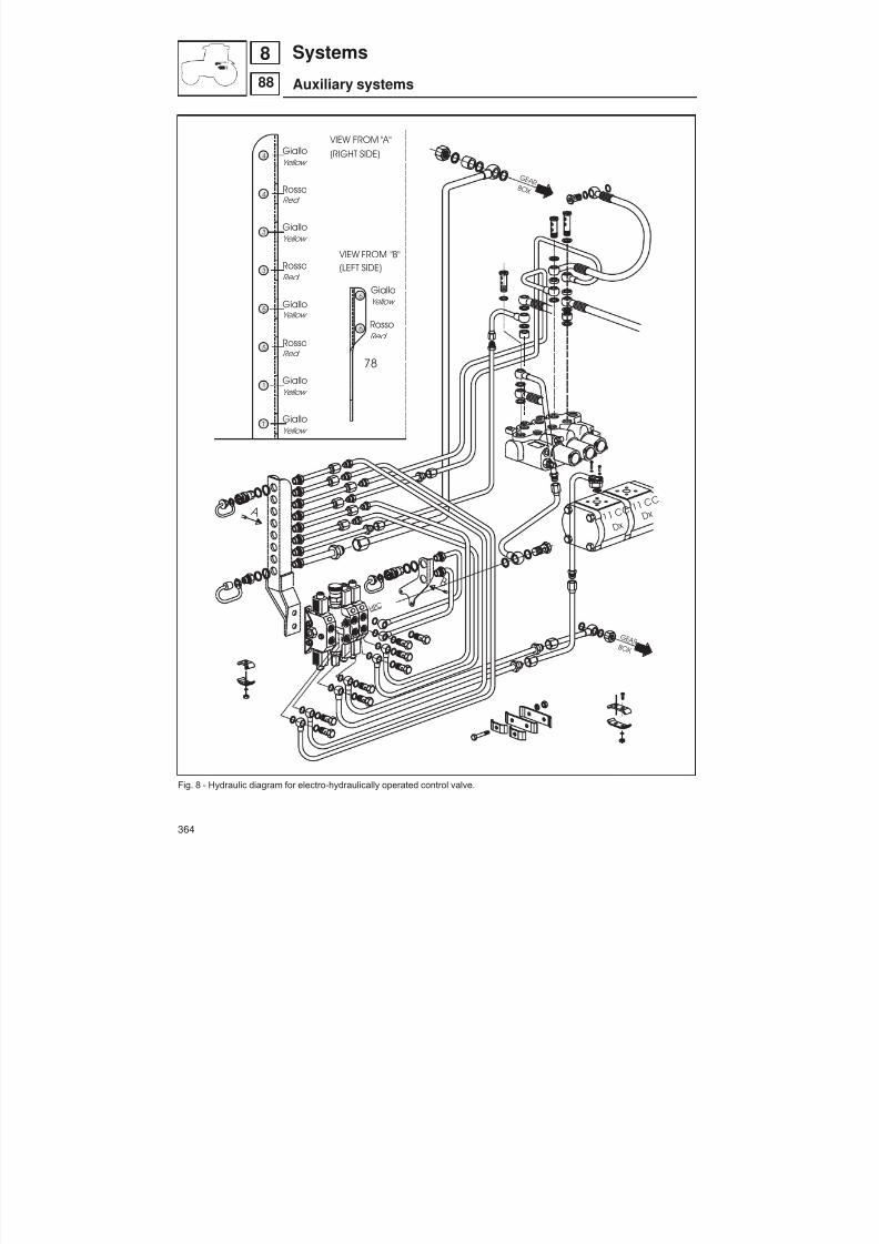
8/19/2019 Agrocompact f60 f70 f80 f90 Repair manual
http://slidepdf.com/reader/full/agrocompact-f60-f70-f80-f90-repair-manual 364/519
Fig. 8 - Hydraulic diagram for electro-hydraulically operated control valve.
364
88
8 Systems
Auxiliary systems
1 1 C C
D x
1 1 C C
D x
4
4
3
3
5
5
T
1
6
6
B
VIEW FROM "A"
G E A R B O X
G E A R B O X
(RIGHT SIDE)
VIEW FROM "B"(LEFT SIDE)
T
P
H P C
Yellow Giallo
RossoRed
GialloYellow
RossoRed
GialloYellow
RossoRed
GialloYellow
GialloYellow
GialloYellow
RossoRed
78
A

8/19/2019 Agrocompact f60 f70 f80 f90 Repair manual
http://slidepdf.com/reader/full/agrocompact-f60-f70-f80-f90-repair-manual 365/519
Fig. 9 - 6-way auxiliary control valve with electro-hydraulic controls.
DSE 2 - Screw to convert from double-acting to single-acting control valve VDP 2 - FLOW DIVIDER valve for adjustment of oil flow rate.RV 1 - Safety valve4 - 4 - Hydraulic ways located in middle of tractor on right-hand side; controlled by rocker switch located on
left-hand side of console.5 - 5 - Hydraulic ways located in middle of tractor on right-hand side; controlled by joystick.6 - 6 - Hydraulic ways located in middle of tractor on left-hand side; controlled by joystick.
365
88
8Systems
Auxiliary systems
DSE2
T
P 4
5
RV1
VDP2
6
6
5
4

8/19/2019 Agrocompact f60 f70 f80 f90 Repair manual
http://slidepdf.com/reader/full/agrocompact-f60-f70-f80-f90-repair-manual 366/519
A3B3
1
0
2
E
RV1
R
P
T
E
T
Priority flow
R e s i d u a l
f l o w
VDP
Pr
190bar
A2
1
0
2
B2 A1
1
0
2
B1 T
HPC
DSE
Attacco conn. DIN 43650
T
P
HPC
Fig. 10 - Solenoid valvesfor control of auxiliaryservicecontrol valves(control valve located in centreof tractor on right-hand side)
HPC – Oil flow to electrohydraulic control unit for stabilisers and lift rod adjustment.
366
88
8 Systems
Auxiliary systems
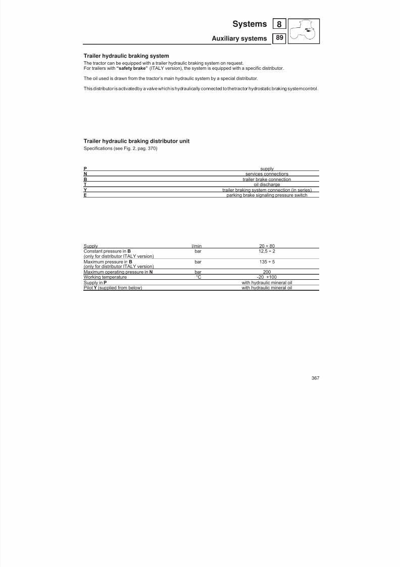
8/19/2019 Agrocompact f60 f70 f80 f90 Repair manual
http://slidepdf.com/reader/full/agrocompact-f60-f70-f80-f90-repair-manual 367/519
Trailer hydraulic braking systemThe tractor can be equipped with a trailer hydraulic braking system on request.
For trailers with “safety brake” (ITALY version), the system is equipped with a specific distributor.
The oil used is drawn from the tractor’s main hydraulic system by a special distributor.
This distributor is activatedby a valve whichis hydraulically connected to thetractor hydrostatic braking systemcontrol.
Trailer hydraulic braking distributor unitSpecifications (see Fig. 2, pag. 370)
P supplyN services connectionsB trailer brake connectionT oil discharge Y trailer braking system connection (in series)E parking brake signaling pressure switch
Supply l/min 20 ÷ 80Constant pressure in B bar 12,5 ÷ 2(only for distributor ITALY version)Maximum pressure in B bar 135 ÷ 5(only for distributor ITALY version)Maximum operating pressure in N bar 200Working temperature °C -20 +100Supply in P with hydraulic mineral oilPilot Y (supplied from below) with hydraulic mineral oil
367
89
8Systems
Auxiliary systems

8/19/2019 Agrocompact f60 f70 f80 f90 Repair manual
http://slidepdf.com/reader/full/agrocompact-f60-f70-f80-f90-repair-manual 368/519
Hydraulic control valve
Trailer brake control lever
Sensor for indicator light on console
Connection to handbrake
Fig. 1 - Hydraulic system for hydraulic trailer braking - ITALY version.
368
89
8 Systems
Auxiliary systems
8/19/2019 Agrocompact f60 f70 f80 f90 Repair manual
http://slidepdf.com/reader/full/agrocompact-f60-f70-f80-f90-repair-manual 369/519
Use of the tractor with CUNA 341/01 hydraulic trailer braking
The trailer hitched to a tractor equippedwith this type of trailer braking requiresa constant pressureof 12.5 ± 2.5bar inorder to release the parking brake ( spring operated).
Therefore, before hitching or unhitching the trailer, this pressure must be eliminated at the coupler by switching off theengine, or better still, by applying the tractor handbrake.
The female quick-action couplers are specially-designed to remain connected if the internal pressure exceeds1.5 bar.
Unless the driver waits the few seconds required to eliminate thepressure, thecoupling or uncoupling operationwill beextremely difficult if not impossible.
The correct type of femalecoupler inserts aremarked FASTER VFBO/1815F and can also be identified by the releasering, which is 44 mm in diameter and 38 mm long.
When uncoupling is performed to hastily, thepressurein the trailer's hydraulic systemwill lock thecoupling, and in addi-tion to compromising the efficiency of the emergency brake , it will prevent re-coupling.
In this event:
— Uncouple the push-pull coupler which passes through the reservoir mounted on the trailer, by pulling on the pipeconnecting the trailer to the tractor.
— Discharge the pressure.
— Re-couple
Special recommendations
In order to changefrom parking brake applied from the trailer (tractor handbrake in lowered position) to efficientservicebraking, the tractor needs to send large quantities of oil to the cylinders.Some time is therefore required before trailer braking reaches full efficiency and therefore, should it be necessary touse the service brake urgently, after having released the parking brake, accelerate the engine to maximumspeed before releasing the tractor handbrake.
In general, remember that if the engine revs are high, braking will be more responsive.
Users who have trailers with "France" type non-type approved hydraulic braking may adapt the SAFIM brake valve tothis type of operation by unscrewing thehex socketscrew on thepilotside cover by three turns (6 mmAllenwrench).In this way, the 12.5 bar pressure is eliminated, the red light remains on, only going out on braking.
It is dangerous to leave thevalve by-pass lever in thebraking position; trailers which do not conform to theCuna 341/01standard are not equipped any protection against this.
The lever on the valve serves to completely by-pass the valve when trailers are not to be hitched to the tractor for longperiods (on trailers which conform to the Cuna 341/01 standard, even if the lever is left in the OFF position, the trailer parking brake is not released).
369
89
8Systems
Auxiliary systems
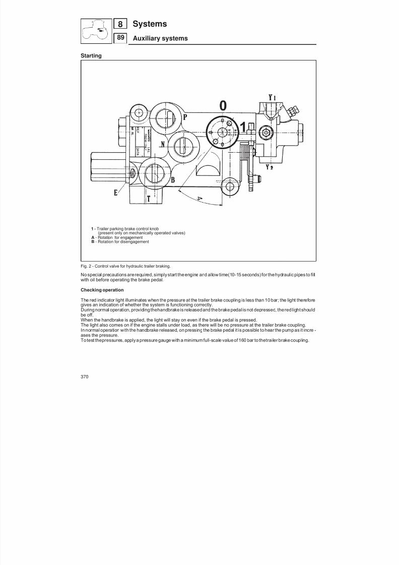
8/19/2019 Agrocompact f60 f70 f80 f90 Repair manual
http://slidepdf.com/reader/full/agrocompact-f60-f70-f80-f90-repair-manual 370/519
Starting
1 - Trailer parking brake control knob(present only on mechanically operated valves)
A - Rotation for engagementB - Rotation for disengagement
Fig. 2 - Control valve for hydraulic trailer braking.
No special precautions arerequired, simplystart theengine and allow time(10-15 seconds) for thehydraulic pipes to fillwith oil before operating the brake pedal.
Checking operation
The red indicator light illuminates when the pressure at the trailer brake coupling is less than 10 bar; the light thereforegives an indication of whether the system is functioning correctly.Duringnormal operation, providingthehandbrake is releasedand thebrake pedal is not depressed, thered light shouldbe off.When the handbrake is applied, the light will stay on even if the brake pedal is pressed.The light also comes on if the engine stalls under load, as there will be no pressure at the trailer brake coupling.In normal operation with the handbrake released, on pressing the brake pedal it is possible to hear the pump as it incre -ases the pressure.
To test thepressures, applya pressure gauge with a minimumfull-scale valueof 160 bar to thetrailer brakecoupling.
370
89
8 Systems
Auxiliary systems
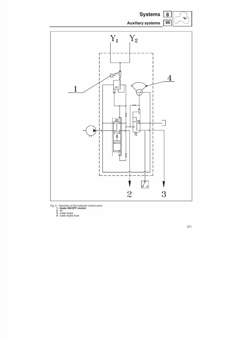
8/19/2019 Agrocompact f60 f70 f80 f90 Repair manual
http://slidepdf.com/reader/full/agrocompact-f60-f70-f80-f90-repair-manual 371/519
Fig. 3 - Operation of the hydraulic control valve1 - brake ON/OFF control2 - lift3 - trailer brake4 - trailer brake lever
371
89
8Systems
Auxiliary systems
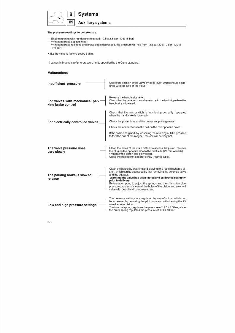
8/19/2019 Agrocompact f60 f70 f80 f90 Repair manual
http://slidepdf.com/reader/full/agrocompact-f60-f70-f80-f90-repair-manual 372/519
The pressure readings to be taken are:
— Engine running with handbrake released: 12.5 ± 2.5 bar (10 to15 bar) — With handbrake applied: 0 bar — With handbrake released and brake pedal depressed, the pressure will rise from 12.5 to 130 ± 10 bar (120 to
140 bar).
N.B.: the valve is factory-set by Safim.
( ) values in brackets refer to pressure limits specified by the Cuna standard.
Malfunctions
Insufficient pressure
For valves with mechanical par -king brake control
For electrically controlled valves
The valve pressure risesvery slowly
The parking brake is slow torelease
Low and high pressure settings
Check the position of the valve by-pass lever, which should be ali -gned with the axis of the valve.
Release the handbrake lever.Check that the lever on the valve returns to the limit stop when thehandbrake is lowered.
Check that the microswitch is functioning correctly (operatedwhen the handbrake is lowered).
Check the power fuse and the power supply in general.
Check the connections to the coil on the two opposite poles.
If the coil is energised, by loosening the retaining nut it is possibleto feel the pull of the magnet; the coil will be very hot.
Clean the holes of the main piston; to access the piston, removethe plug on the opposite side to the pilot side (27 mm wrench).Withdraw the piston and blow clean.Close the hex socket adapter screw (France type).
Clean the holes (by washing and blowing) the rapid discharge pi -ston, which can be accessed by first removing the solenoid valveand the adapter.Warning: the valve has been tested and calibrated correctlyprior to delivery.Before attempting to adjust the springs and the shims, to solvepressure problems, clean all the holes of the piston and solenoidvalve with petrol and compressed air.
The pressure settings are regulated by way of shims, which can
be accessed by removing the pilot valve and withdrawing the 25mm diameter piston.The internal spring regulates the pressure of 12.5 ± 2.5 bar, whilethe outer spring regulates the pressure of 130 ± 10 bar.
372
89
8 Systems
Auxiliary systems

8/19/2019 Agrocompact f60 f70 f80 f90 Repair manual
http://slidepdf.com/reader/full/agrocompact-f60-f70-f80-f90-repair-manual 373/519
Fig. 4 - View of the hydraulic control valve.
1 - Lever position with handbrake fully applied2 - Start of trailer braking3 - Lever position with handbrake released
373
89
8Systems
Auxiliary systems
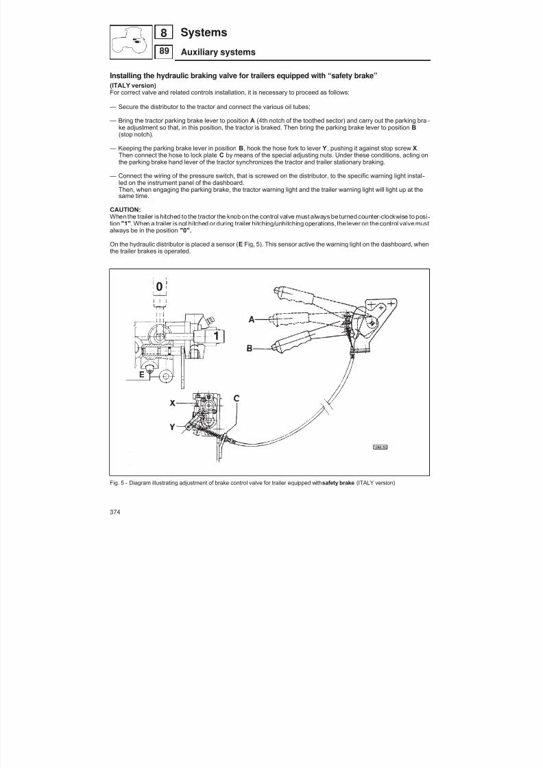
8/19/2019 Agrocompact f60 f70 f80 f90 Repair manual
http://slidepdf.com/reader/full/agrocompact-f60-f70-f80-f90-repair-manual 374/519
Installing the hydraulic braking valve for trailers equipped with “safety brake”(ITALY version)
For correct valve and related controls installation, it is necessary to proceed as follows:
— Secure the distributor to the tractor and connect the various oil tubes;
— Bring the tractor parking brake lever to position A (4th notch of the toothed sector) and carry out the parking bra -ke adjustment so that, in this position, the tractor is braked. Then bring the parking brake lever to position B(stop notch).
— Keeping the parking brake lever in position B, hook the hose fork to lever Y, pushing it against stop screw X.Then connect the hose to lock plate C by means of the special adjusting nuts. Under these conditions, acting onthe parking brake hand lever of the tractor synchronizes the tractor and trailer stationary braking.
— Connect the wiring of the pressure switch, that is screwed on the distributor, to the specific warning light instal -led on the instrument panel of the dashboard.Then, when engaging the parking brake, the tractor warning light and the trailer warning light will light up at thesame time.
CAUTION:When the trailer is hitched to the tractor the knob on the control valve must always be turned counter-clockwise to posi -tion "1" . When a trailer is not hitched or during trailer hitching/unhitching operations, the lever on thecontrol valve mustalways be in the position "0".
On the hydraulic distributor is placed a sensor ( E Fig, 5). This sensor active the warning light on the dashboard, whenthe trailer brakes is operated.
Fig. 5 - Diagram illustrating adjustment of brake control valve for trailer equipped with safety brake (ITALY version)
374
89
8 Systems
Auxiliary systems

8/19/2019 Agrocompact f60 f70 f80 f90 Repair manual
http://slidepdf.com/reader/full/agrocompact-f60-f70-f80-f90-repair-manual 375/519
Fig. 6 - Components of the hydraulic control valve - FRANCE version.
375
89
8Systems
Auxiliary systems
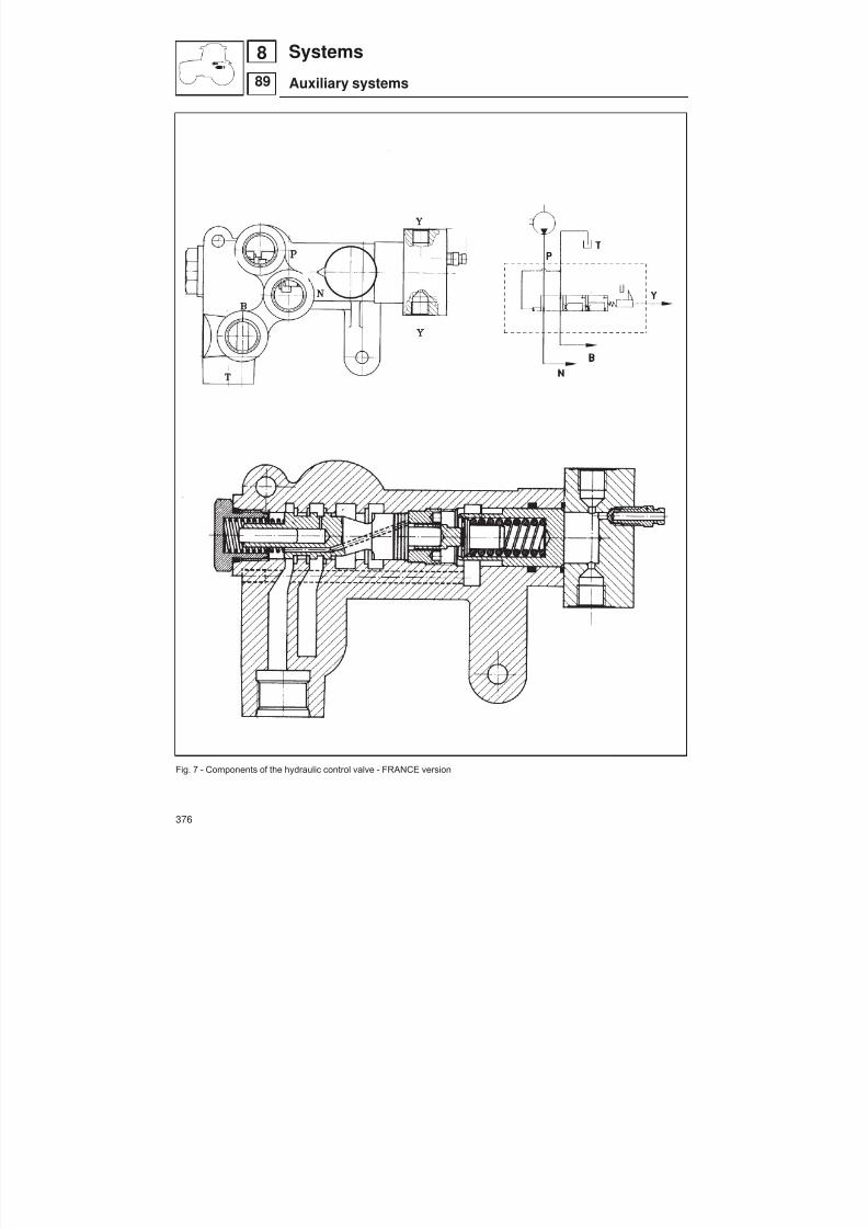
8/19/2019 Agrocompact f60 f70 f80 f90 Repair manual
http://slidepdf.com/reader/full/agrocompact-f60-f70-f80-f90-repair-manual 376/519
Fig. 7 - Components of the hydraulic control valve - FRANCE version
376
89
8 Systems
Auxiliary systems

8/19/2019 Agrocompact f60 f70 f80 f90 Repair manual
http://slidepdf.com/reader/full/agrocompact-f60-f70-f80-f90-repair-manual 377/519
General specificationsThe electrical systemis fully equipped foruseon theroad, with sidelights,main/dipped beamheadlamps, direction indi -catorsdoubling as hazard warning lights, and work lights, all fully in compliance with legal requirements as embodied inthe highway code.
There are four essential components and assemblies: battery, alternator, starter motor, and auxiliaries.
The system operates at a nominal 12 Volts (the maximum voltage in operation is 14,3 ÷ 0,5 V).
The battery charge level is indicated by a relative meter on the instrument panel.
specifications
batterytype maintenance freevoltage V 12discharge capacity over 20 hours Ah 100rated current A 470
starter motor60 - 70 CV 80 - 90 CV
code (BOSCH) 2.9619.300.0/10 2.9619.290.0/10voltage V 12 12
nominal rated power cv 3,4 (2,6 kW) 4 (3 kW)electromagnetic control electro-magnetic with translation
and rotation of pinion
alternator RECHARGE SYSTEMcode 65A MARELLI 2.9439.400.0
65A BOSCH 2.9439.410.065A ISKRA 2.9439.420.0/10ISKRA 85A 2.9439.460.0/10
type three-phasenominal rated voltage V 12pulley nut tightening torque kgm 5,5 (62 Nm)
377
84
8Systems
Electrical system

8/19/2019 Agrocompact f60 f70 f80 f90 Repair manual
http://slidepdf.com/reader/full/agrocompact-f60-f70-f80-f90-repair-manual 378/519
GENERAL SAFETY DIRECTIONSPRECAUTIONS AGAINST DAMAGE TO ELECTRICAL AND ELECTRONIC EQUIPMENT
— Disconnect any electronic equipment from the system when the tractor is placed in any environment where tempe -ratures are likely to exceed 80 °C.
— Remove battery connections when carrying out servicing or repair operations on the electrical system.
— Avoid overvoltages in the electrical system. Always remove battery and alternator connections before carrying outwelding operations or when recharging the battery from the mains.
— Never disconnect the battery while the engine is running.
— In theevent that thebattery needs topping up,useonly distilledor demineralized water; topup only when thebatteryis AT REST and at AMBIENT TEMPERATURE (allow time for cooling after operation and following recharge).
— Never carry out servicing operations on the electric heating system with the engine running.
— When washing the tractor, ensure that the alternator and starter motor are well protected. These components mustnot be sprayed or splashed directly with water.
PRECAUTIONS AGAINST ACCIDENT AND INJURYWHEN COMMENCING ANY KIND OF WORK:
— Turn off the main ignition switch.— Disconnect the battery; remember that electric shocks discharged through the human body will damage pacema -
kers.
— Thebattery generatespowerfuland inflammablegases when recharging,which if ignited cancausethe battery itself to explode.
— Do not make temporary or makeshift connections to the battery, as these can cause dangerous sparks.
— The electrolyte in the battery is a solution of dilute sulphuric acid; if splashed on the skin, wash straight away withplenty of water and sodium bicoarbonate.
— Seek attention immediately from a doctor if electrolyte is splashed into the eyes.
— Never allow the battery near a naked flame.
— Keep a safedistance froma rechargingbatterywhen testingor measuring, andalwayswear suitableeyeprotection.
— Make certain that the electrical system and all its components are inspected and serviced periodically; any faultsmust be eliminated without delay, and parts subject to everyday wear replaced at the recommended intervals.
— Ensure that trailers are fitted with regulation lights.
IMPORTANT REMINDERSThe maker declines all liability in respect of any damages resulting from operations performedother than in the recom -mended manner and/or by unskilled hands.
— To ensure smooth operation of the machine, use only genuine replacement parts.
378
84
8 Systems
Electrical system

8/19/2019 Agrocompact f60 f70 f80 f90 Repair manual
http://slidepdf.com/reader/full/agrocompact-f60-f70-f80-f90-repair-manual 379/519
JUMP START UTILIZING ANOTHER BATTERYNB: Emergency starting with the aid of a battery charger is not recommended.
PRECAUTIONSThe battery may be that of another tractor, but must in any event have thesameratedvoltage (and thereforean identicalnumber of cells).
1 - Make certain the two vehicles are not in contact with one another.
2 - Ensure that all auxiliary services are switched off.
3 - Make certain theflat battery is securely connected to earth, that thefiller caps areproperly tightened and that theelectrolyte is up to the correct level.
PROCEDURE:A - Connect the two batteries as indicated in figure 1 (part A).
B - If the jump battery is that of another tractor, start the engine and run at approximately 1/4 of full throttle.
C - Turn the ignition key to start the engine of the stranded tractor, following the procedure given in the operator’shandbook.
D - Remove the jump leads following the sequence as indicated in figure 1 (part B).
A - connection of leads tothe 2 batteries B - disconnection of leads from the2 batteries
SeparateBatteries
connected batteries
STEP 1 STEP 4
STEP 5
STEP 2
STEP 6
STEP 3
connected batteries separate batteries
Fig. 1 - Diagram of battery connections and relative leads.
379
84
8Systems
Electrical system

8/19/2019 Agrocompact f60 f70 f80 f90 Repair manual
http://slidepdf.com/reader/full/agrocompact-f60-f70-f80-f90-repair-manual 380/519
PRACTICAL HINTS
Before installing a battery, and periodically thereafter:— Check over the electrical system, giving particular attention to connections; make certain there are no traces of oxi -
dation and that there is no loss of current.— Check the alternator and the voltage regulator setting. If the charging voltage is inordinately high, distilledwater will
be consumed at a high rate, whereas a low voltage will not charge the battery sufficiently.— Check the charge level of a new battery with a density indicator or voltmeter; if the density is less than1.25kg/l or the
no-load voltage after at least 3 - 4 hours at rest is lower than 12.5 V, proceed to recharge.Install the battery in the machine with care, utilizing the anchorages provided.
When connecting the battery to the system:— secure the clamp.— before connecting the negative, make certain there is no sparking on contact with the corresponding terminal of the
battery. Sparks are due to insulation defects that must be located and eliminated.— Tighten the clamps on the terminals, smearing with petroleum jelly.
TABLE OF WIRING COLOUR CODES
BK = BLACK EXAMPLE:BL = BLUE BR = BROWN DK BL/WH 1 680DK BL = DARK BLUE DK GN = DARK GREEN DK BL/WH = DARK BLUE WITH WHITE LINE GN = GREEN GY = GREY 1 = CROSS SECTION OF WIRE (mm)OR = ORANGE 680 = LENGTH OF WIRE (mm )PK = PINK RD = RED VL = VIOLET WH = WHITE YL = YELLOW
EXAMPLE OF CONNECTORS (CAN BE 4-PIN, 6-PIN OR 8-PIN)
380
84
8 Systems
Electrical system
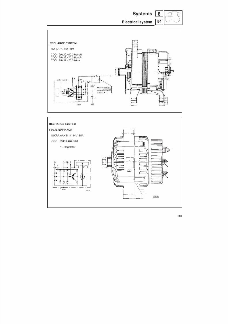
8/19/2019 Agrocompact f60 f70 f80 f90 Repair manual
http://slidepdf.com/reader/full/agrocompact-f60-f70-f80-f90-repair-manual 381/519
RECHARGE SYSTEM
65A ALTERNATOR
COD. 29439.400.0 Marelli COD. 29439.410.0 BoschCOD. 29439.410.0 Iskra
RECHARGE SYSTEM
65A ALTERNATOR
ISKRA AAK5114 14V 85A
COD. 29439.460.0/10
1 - Regolator
381
84
8Systems
Electrical system
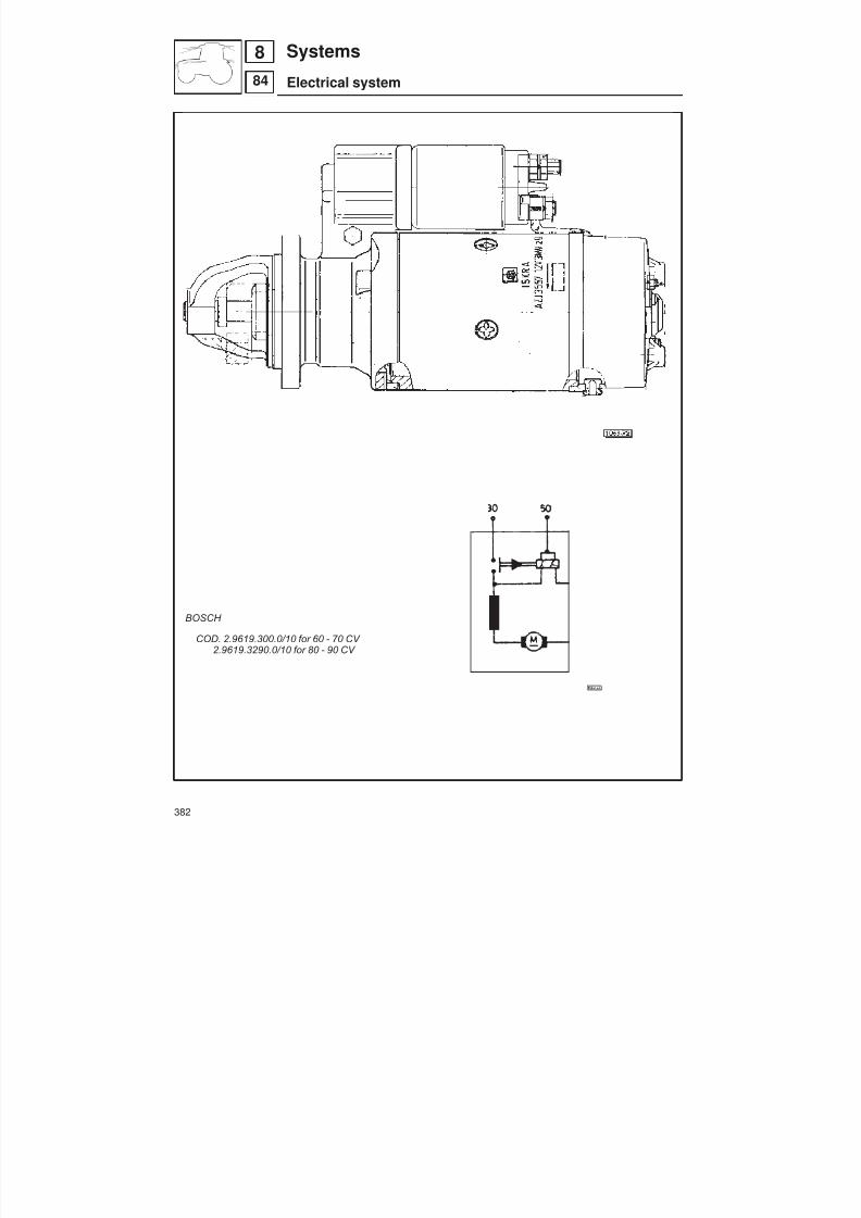
8/19/2019 Agrocompact f60 f70 f80 f90 Repair manual
http://slidepdf.com/reader/full/agrocompact-f60-f70-f80-f90-repair-manual 382/519
STARTING SYSTEM
ISKRA
COD. 2.9619. 360.0 for 60 - 70 CV 2.9619. 350.0 for 80 - 90 CV
BOSCH
COD. 2.9619.300.0/10 for 60 - 70 CV 2.9619.3290.0/10 for 80 - 90 CV
382
84
8 Systems
Electrical system
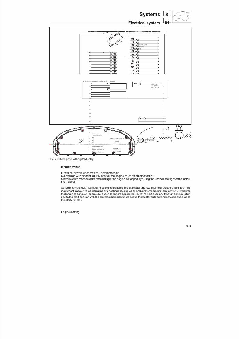
8/19/2019 Agrocompact f60 f70 f80 f90 Repair manual
http://slidepdf.com/reader/full/agrocompact-f60-f70-f80-f90-repair-manual 383/519
21
25
13
30
29
28
17
8
9
7
11
27
SCHEMA ELETTRICO INTERNO/ELECTRIC DIAGRAM
15
10
14
33 VCC lights
26
12
20
VCC Spie32
1
24
23
22
6
18
16
P2
P1
P3
Temperatura mot.
Livello carburante
Velocita' motore
Velocita' ruote
36
5
4
2
35
34
3
MICRO CONTROLLO
STRUMENTI
INDICATORI
DISPLAY
ETICHETTA ADESIVA
ACQUA 10N DIGIT
ADESIV LABEL
3 1 1 1 9
2
1
1 0
2 4
3 4
1 4
2 8 2 0
2 1
3 0
2 9
4 1 2
1 3
2 2
3 1 2 3
3 3 3 2
1 8 2 6
5
6
1 7
7 1 5
2 5
1 6 8
9
2 7 3 5
3 6
ILLUMINAZIONE
GND Spie 31
19
Fig. 2 - Check panel with digital display
383
84
8Systems
Electrical system
Ignition switch
Electtrical system deenergized - Key removable(On version with electronic RPM control, the engine shuts off automatically;On versio with machanical throttle linkage, the engine is stopped by pulling the knob on the right of the instru -ment panel).
Active electric circyit: - Lamps indicating operation of the alternator and low engine oil pressure light up on theinstrument panel. A lamp indicating pre-heating lights up when ambient temperature is below 10°C; wait untilthe lamphas goneout (approx. 55seconds) before turning the key to the next position. If the ignitionkey is tur -ned to the start position with the thermostart indicator still alight, the heater cuts out and power is supplied tothe starter motor.
Engine starting

8/19/2019 Agrocompact f60 f70 f80 f90 Repair manual
http://slidepdf.com/reader/full/agrocompact-f60-f70-f80-f90-repair-manual 384/519
IGNITION KEYmachines with mechanical throttlelinkage p/n 2.7659.071.0/30
machines with electronic rpmcod. 2.7659.127.0
VENTILATION CONTROLmachines with cab
PUSH BUTTON CONTROL
CODE 2.7659.110.0
HAZARD WARNING LIGHTS
384
84
8 Systems
Electrical system
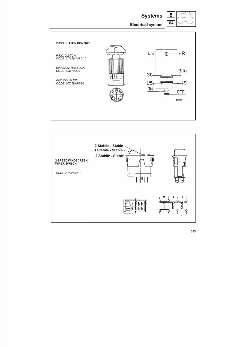
8/19/2019 Agrocompact f60 f70 f80 f90 Repair manual
http://slidepdf.com/reader/full/agrocompact-f60-f70-f80-f90-repair-manual 385/519
PUSH BUTTON CONTROL
P.T.O. CLUTCH CODE 2.7659.108.0/10
DIFFERENTIAL LOCK CODE 008.1335.0
4WD COUPLER
CODE 007.5945.0/20
2-SPEED WINDSCREENWIPER SWITCH
CODE 2.7659.092.0
385
84
8Systems
Electrical system

8/19/2019 Agrocompact f60 f70 f80 f90 Repair manual
http://slidepdf.com/reader/full/agrocompact-f60-f70-f80-f90-repair-manual 386/519
WORK LIGHTS
FRONT CODE 2.7659.078.0
REAR COD. 2.7659.079.0
SCREEN WASHER SWITCH
FRONT CODE 2.7659.091.0
BEACON PUSH BUTTON
CODE 2.7659.126.0
386
84
8 Systems
Electrical system
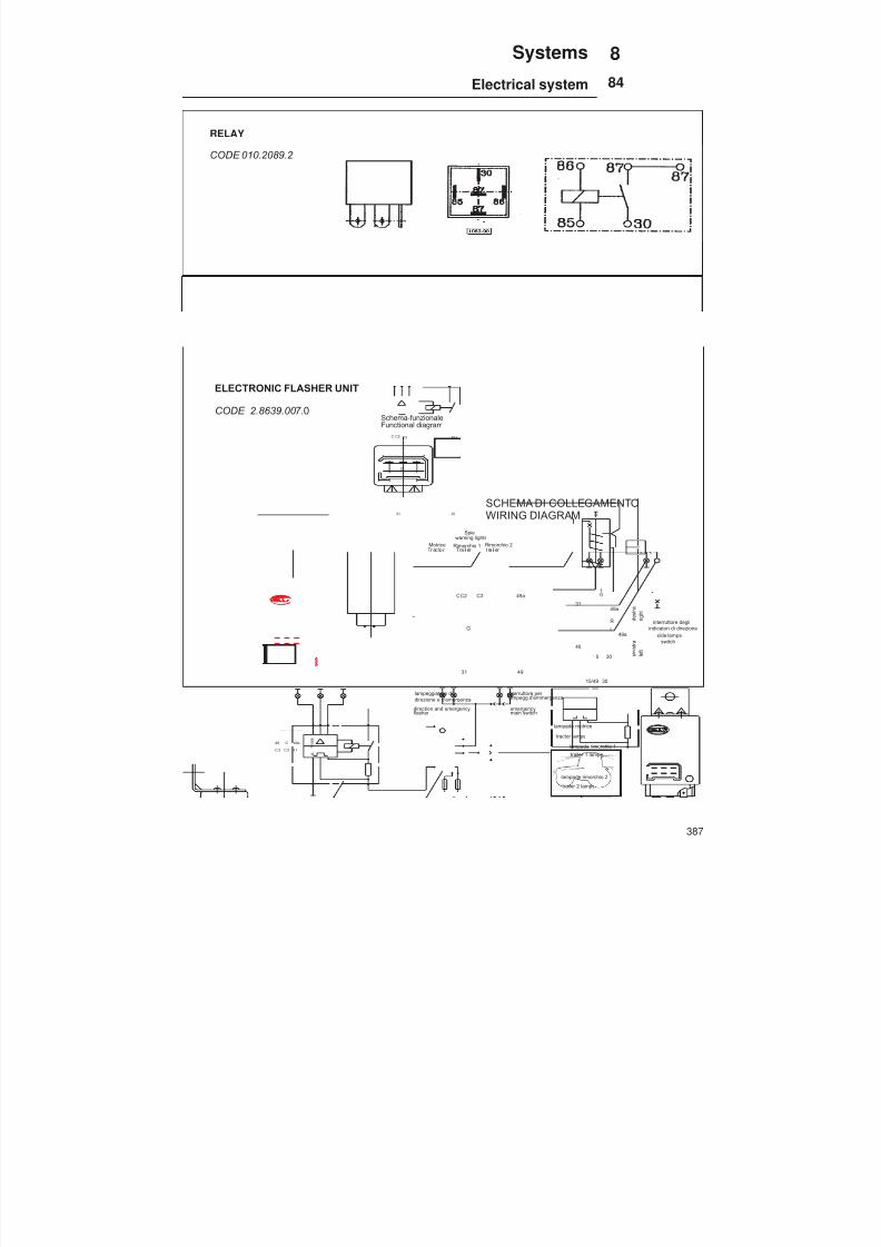
8/19/2019 Agrocompact f60 f70 f80 f90 Repair manual
http://slidepdf.com/reader/full/agrocompact-f60-f70-f80-f90-repair-manual 387/519
49 C 49a
C 3 C 2 3 1 7 1 4 5 8
A
Made In Germany
4DN 006 208-0112V21W2+1+1(8)P
TB83BLINKGEBR
Tr ac to r Tra il er t ra il er
lampeggiatore didirezione e d'emergenza
main switchemergency
indicatori di direzione
tractor lamps
C C2 C3 49a
31 49
G
01
49a
R
L49a
15 30
49
3015/49
31
s i n i s t r a
d e s t r a
31 49
G
C2C C3 49a
Functional diagramSchema-funzionale
SCHEMA DI COLLEGAMENTOWIRING DIAGRAM
warning lightsSpie
Rimorchio 1Motrice Rimorchio 2
flasher direction and emergency
interruttore per lampegg.d'emmergenza
lampade motrice
lampade rimorchio 1
side lamps
l e f t
r i g h t
lampade rimorchio 2
interruttore degli
switch
trailer 1 lamps
trailer 2 lamps
RELAY
CODE 010.2089.2
ELECTRONIC FLASHER UNIT
CODE 2.8639.007. 0
387
84
8Systems
Electrical system
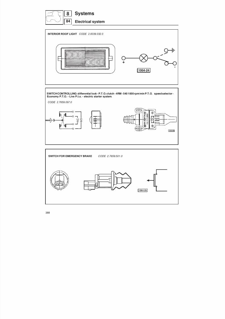
8/19/2019 Agrocompact f60 f70 f80 f90 Repair manual
http://slidepdf.com/reader/full/agrocompact-f60-f70-f80-f90-repair-manual 388/519
INTERIOR ROOF LIGHT CODE 2.8339.032.0
SWITCHCONTROLLING:differential lock - P.T.O. clutch - 4RM - 540 1000 rpm/min P.T.O. speed selector -Economy P.T.O. - Live P.t.o. - electric starter system .
CODE 2.7659.097.0
SWITCH FOR EMERGENCY BRAKE CODE 2.7659.501.0
388
84
8 Systems
Electrical system
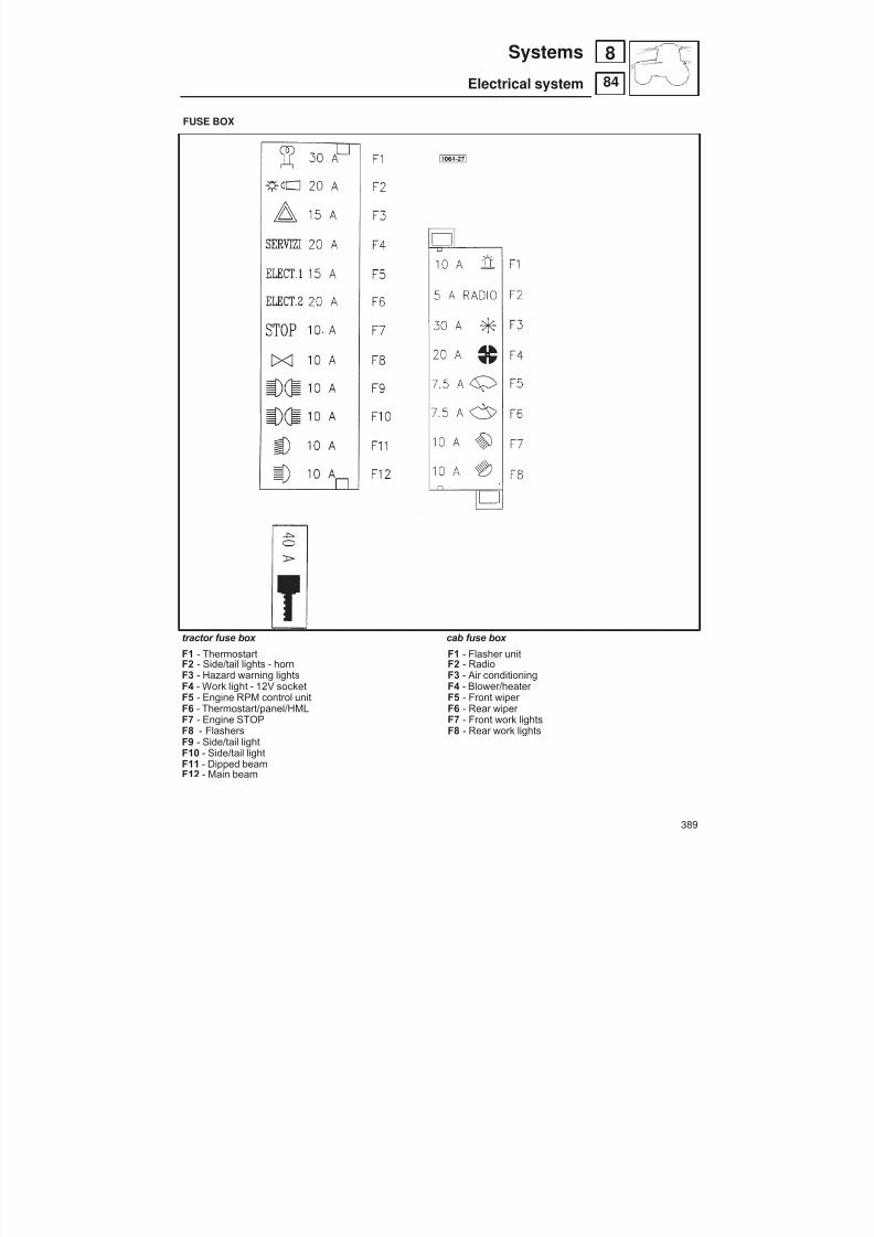
8/19/2019 Agrocompact f60 f70 f80 f90 Repair manual
http://slidepdf.com/reader/full/agrocompact-f60-f70-f80-f90-repair-manual 389/519
FUSE BOX
389
84
8Systems
Electrical system
F1 - ThermostartF2 - Side/tail lights - hornF3 - Hazard warning lightsF4 - Work light - 12V socketF5 - Engine RPM control unitF6 - Thermostart/panel/HMLF7 - Engine STOPF8 - FlashersF9 - Side/tail lightF10 - Side/tail lightF11 - Dipped beamF12 - Main beam
F1 - Flasher unitF2 - RadioF3 - Air conditioningF4 - Blower/heater F5 - Front wiper F6 - Rear wiper F7 - Front work lightsF8 - Rear work lights
tractor fuse box cab fuse box

8/19/2019 Agrocompact f60 f70 f80 f90 Repair manual
http://slidepdf.com/reader/full/agrocompact-f60-f70-f80-f90-repair-manual 390/519
Instrument panel with digital display
The basic panel is the same as described above, except that the dial is replaced by a 4-digit display showing:
— Lapsed time (hours) — Ground speed (speedometer) — P.T.O. speed — Trip meter (distance in metres)
There are also 4 high brightness Leds which indicate the function currently being displayed. Any specifications not individually listed below will be the same as for the basic panel.
OperationThe selection and content of the functions displayed are governed by pressing buttons, denoted P1 , P2 and P3 .
Button P1 - Red - Positioned to right of panel.Button P2 - Red - Positioned to right of panel.Button P3 - Red - Positioned near fuse box (cover must be removed to gain access).
Auxiliary electrical systems on(turn the ignitionkeytoposition ) the current total of working hours lapsedwill be displa -
yed.
Then, turn the ignitionkey toposition , whenthe engineis started, the display sets itself to indicate groundspeed(speedometer).
To display a function other than ground speed, simply press P1 repeatedly to select the function required.
1 - Lapsed work time indicated by 4 digits, to the nearest hour.
2 - Ground speed indicated by 3 digits, one of which after the decimal point (XX.X), in km/h. In the event that bigger or smaller rear tyres are fitted, the new size must be entered (see directions point 5 page 391).
390
84
8 Systems
Electrical system

8/19/2019 Agrocompact f60 f70 f80 f90 Repair manual
http://slidepdf.com/reader/full/agrocompact-f60-f70-f80-f90-repair-manual 391/519
IMPORTANT: If a function other than speedometer is currently selected, the panel will revert automatically to displa -ying ground speed if 20 km/h is exceeded.
3 - P.T.O. speed is indicated by 4 digits (XXX0), in revolutions per minute.
4 - The trip meter uses 4 digits (XXXX), indicating the distance covered by the tractor in metres. The trip meter can bereset; this is done by selecting the function then pressing and holding P2 for at least 3 seconds, during which time the fi -gures will blink before returning to zero. If P2 is released before the 3 seconds have passed, there will be no reset.
5 - Entering the speed constant according to the tyre size .This operation becomes necessary only if the rear tyres are replaced with others of a different size.
Withtheengine atstandstill and the ignitionkeyin the off position , press and holdbutton P3whileturningthekey
to the auxiliary position (without starting the engine), then release the button only when the tyre code appears inthe display. This code will correspond to the type of rear tyre currently fitted.Now press button P1 repeatedly to view the permissible tyre sizes, which will be displayed in sequence.When the size displayed matches that of the new tyres, press P3 again to memorize.If the key is returned to the off position without completing this last step, the tyre size code will not be updated.
Listedbelow arethe tyre options specifiedfor thetractor.Each size has a relative display code whichcorresponds to thenumber of impulses per 100 metres picked up by the speedometer sensor.
Tyre Impulses for 100 metres380/70R20 5792
12.4R24 5768
380/70R20 576813.6R24 5560
380/70R24 5560420/70/24 528012.4R28 5280
360/70R28 528013.6R28 5104
360/70R28 5104420/70R28 4864
1 - Diagnostics socket (on version with electronic RPM controlonly)3 - Tyre size selectionbutton (onversion with theInstrument panelwith digital display)
Button P 1, used to select the function di -splayed - Colour red.The 3 available functions (speedometer,P.T.O. speed, trip meter) are displayedcyclically by pressing P1 repeatedly.Thefunctionselected is indicated by a relati -ve Led on the instrument panel.
Button P 2, used to reset the function se -lected - Colour redPress this to select another function.
391
84
8Systems
Electrical system
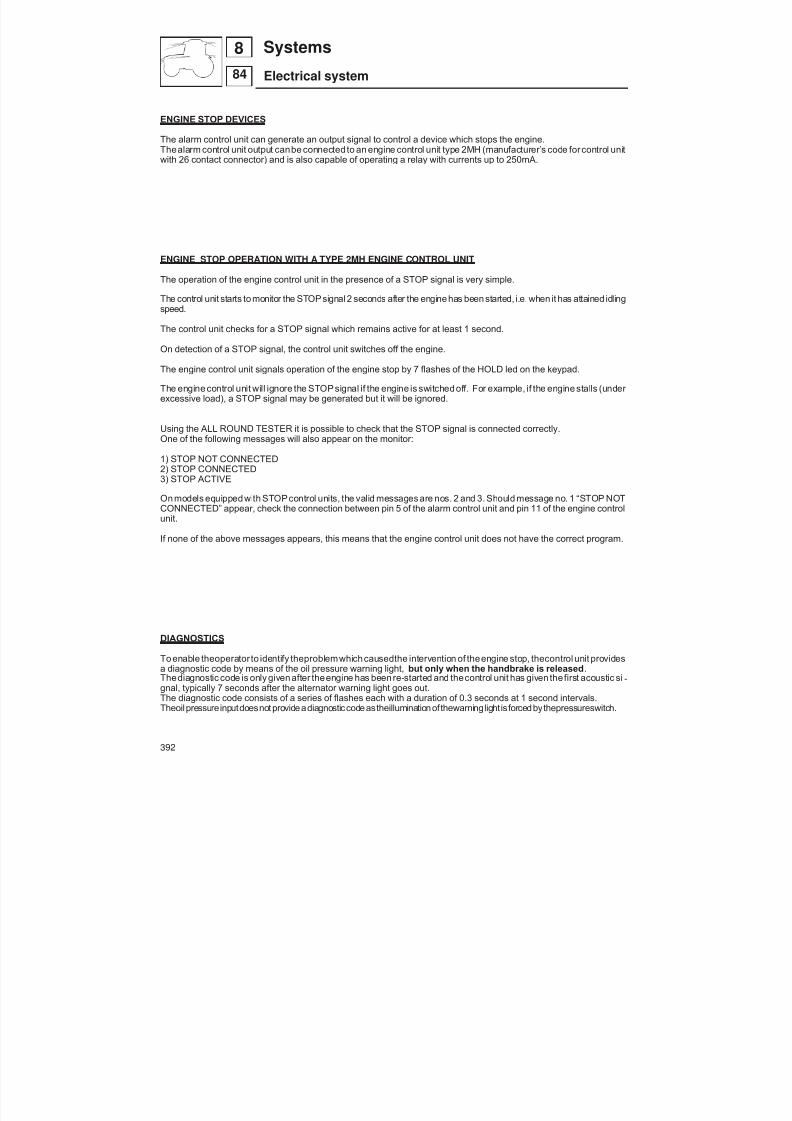
8/19/2019 Agrocompact f60 f70 f80 f90 Repair manual
http://slidepdf.com/reader/full/agrocompact-f60-f70-f80-f90-repair-manual 392/519
ENGINE STOP DEVICES
The alarm control unit can generate an output signal to control a device which stops the engine.Thealarm control unit output canbe connected to an engine control unit type 2MH (manufacturer’s code forcontrol unitwith 26 contact connector) and is also capable of operating a relay with currents up to 250mA.
ENGINE STOP OPERATION WITH A TYPE 2MH ENGINE CONTROL UNIT
The operation of the engine control unit in the presence of a STOP signal is very simple.
The control unit starts to monitor the STOP signal 2 seconds after the engine has been started, i.e. when it has attained idlingspeed.
The control unit checks for a STOP signal which remains active for at least 1 second.
On detection of a STOP signal, the control unit switches off the engine.
The engine control unit signals operation of the engine stop by 7 flashes of the HOLD led on the keypad.
The engine control unit will ignore the STOP signal if the engine is switched off. For example, if the engine stalls (under excessive load), a STOP signal may be generated but it will be ignored.
Using the ALL ROUND TESTER it is possible to check that the STOP signal is connected correctly.One of the following messages will also appear on the monitor:
1) STOP NOT CONNECTED2) STOP CONNECTED3) STOP ACTIVE
On models equipped with STOPcontrol units, the valid messages are nos. 2 and 3. Should message no. 1 “STOP NOTCONNECTED” appear, check the connection between pin 5 of the alarm control unit and pin 11 of the engine controlunit.
If none of the above messages appears, this means that the engine control unit does not have the correct program.
DIAGNOSTICS
To enable theoperator to identify theproblemwhichcausedthe intervention of theengine stop, thecontrol unit providesa diagnostic code by means of the oil pressure warning light, but only when the handbrake is released .
Thediagnostic code is only given after theengine has been re-started and thecontrol unit has given thefirst acoustic si -gnal, typically 7 seconds after the alternator warning light goes out.The diagnostic code consists of a series of flashes each with a duration of 0.3 seconds at 1 second intervals.Theoil pressureinputdoesnot provideadiagnostic codeastheilluminationofthewarninglight isforcedbythepressureswitch.
392
84
8 Systems
Electrical system

8/19/2019 Agrocompact f60 f70 f80 f90 Repair manual
http://slidepdf.com/reader/full/agrocompact-f60-f70-f80-f90-repair-manual 393/519
Diagnostic codes
Below is a list of the diagnostic codes and their meanings:
flashes
WARNING LIGHT
2 Broken fanbelt sensor 3 Alternator signal D+4 Auxiliary input5 Engine STOP output
example of code 2
ON
OFF
Description of faults
This chapter provides useful information for fault tracing.
Code 2 - Broken fanbelt sensor
This fault is signalled when the input signal from the fanbelt sensor fails to arrive at the control unit.If this fault occurs :- Check that the battery voltage is present between pins 1 and 2 of the sensor connector.- Check that pin 3 of the sensor connector is connected to pin 6 of the alarm control unit.
Code 3 - Alternator signal D+
This fault is signalled when the alternator signal D+ is no longer present after the alarm control unit has entered intooperation.If this fault occurs:- Check the alternator warning light: if on, the problem concerns the alternator itself; if off, the wire carrying the signal tothe control unit may have come disconnected.
Code 4 - Auxiliary input
This fault is signalled when the voltage on pin 8 of the control unit falls below 12V.This input is not currently utilised, consequently if this fault is signalled, check that pin 8 of the control unit is at +12V. If necessary, remove the contact from the connector and test again.
Code 5 - Engine STOP output
This fault is signalled when the control unit does not detect any connection to its STOP output.
If this fault occurs:- Check that pin 5 of the alarm control unit is connected to pin 11of the engine control unit.
Brokenbelt alarmsystemanddiagnostic codes. (If thelightstays oncontinuously this indicates lowengineoilpressure).
393
84
8Systems
Electrical system
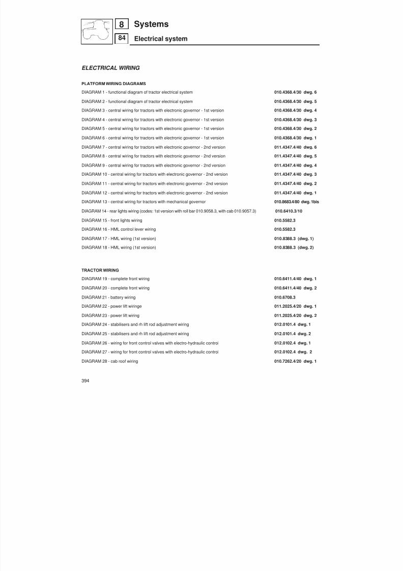
8/19/2019 Agrocompact f60 f70 f80 f90 Repair manual
http://slidepdf.com/reader/full/agrocompact-f60-f70-f80-f90-repair-manual 394/519
ELECTRICAL WIRING
PLATFORM WIRING DIAGRAMS
DIAGRAM 1 - functional diagram of tractor electrical system 010.4368.4/30 dwg. 6
DIAGRAM 2 - functional diagram of tractor electrical system 010.4368.4/30 dwg. 5
DIAGRAM 3 - central wiring for tractors with electronic governor - 1st version 010.4368.4/30 dwg. 4
DIAGRAM 4 - central wiring for tractors with electronic governor - 1st version 010.4368.4/30 dwg. 3
DIAGRAM 5 - central wiring for tractors with electronic governor - 1st version 010.4368.4/30 dwg. 2
DIAGRAM 6 - central wiring for tractors with electronic governor - 1st version 010.4368.4/30 dwg. 1
DIAGRAM 7 - central wiring for tractors with electronic governor - 2nd version 011.4347.4/40 dwg. 6
DIAGRAM 8 - central wiring for tractors with electronic governor - 2nd version 011.4347.4/40 dwg. 5
DIAGRAM 9 - central wiring for tractors with electronic governor - 2nd version 011.4347.4/40 dwg. 4
DIAGRAM 10 - central wiring for tractors with electronic governor - 2nd version 011.4347.4/40 dwg. 3
DIAGRAM 11 - central wiring for tractors with electronic governor - 2nd version 011.4347.4/40 dwg. 2
DIAGRAM 12 - central wiring for tractors with electronic governor - 2nd version 011.4347.4/40 dwg. 1
DIAGRAM 13 - central wiring for tractors with mechanical governor 010.8683.4/80 dwg. 1bis
DIAGRAM 14 - rear lights wiring (codes: 1st version with roll bar 010.9058.3, with cab 010.9057.3) 010.6410.3/10
DIAGRAM 15 - front lights wiring 010.5582.3
DIAGRAM 16 - HML control lever wiring 010.5582.3
DIAGRAM 17 - HML wiring (1st version) 010.8388.3 (dwg. 1)
DIAGRAM 18 - HML wiring (1st version) 010.8388.3 (dwg. 2)
TRACTOR WIRING
DIAGRAM 19 - complete front wiring 010.6411.4/40 dwg. 1
DIAGRAM 20 - complete front wiring 010.6411.4/40 dwg. 2
DIAGRAM 21 - battery wiring 010.6708.3
DIAGRAM 22 - power lift wiringe 011.2025.4/20 dwg. 1
DIAGRAM 23 - power lift wiring 011.2025.4/20 dwg. 2
DIAGRAM 24 - stabilisers and rh lift rod adjustment wiring 012.0101.4 dwg. 1
DIAGRAM 25 - stabilisers and rh lift rod adjustment wiring 012.0101.4 dwg. 2
DIAGRAM 26 - wiring for front control valves with electro-hydraulic control 012.0102.4 dwg. 1
DIAGRAM 27 - wiring for front control valves with electro-hydraulic control 012.0102.4 dwg. 2
DIAGRAM 28 - cab roof wiring 010.7262.4/20 dwg. 1
394
84
8 Systems
Electrical system
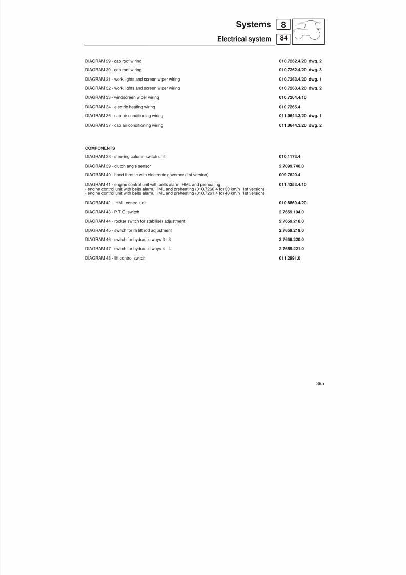
8/19/2019 Agrocompact f60 f70 f80 f90 Repair manual
http://slidepdf.com/reader/full/agrocompact-f60-f70-f80-f90-repair-manual 395/519
DIAGRAM 29 - cab roof wiring 010.7262.4/20 dwg. 2
DIAGRAM 30 - cab roof wiring 010.7262.4/20 dwg. 3
DIAGRAM 31 - work lights and screen wiper wiring 010.7263.4/20 dwg. 1
DIAGRAM 32 - work lights and screen wiper wiring 010.7263.4/20 dwg. 2
DIAGRAM 33 - windscreen wiper wiring 010.7264.4/10
DIAGRAM 34 - electric heating wiring 010.7265.4
DIAGRAM 36 - cab air conditioning wiring 011.0644.3/20 dwg. 1
DIAGRAM 37 - cab air conditioning wiring 011.0644.3/20 dwg. 2
COMPONENTS
DIAGRAM 38 - steering column switch unit 010.1173.4
DIAGRAM 39 - clutch angle sensor 2.7099.740.0
DIAGRAM 40 - hand throttle with electronic governor (1st version) 009.7620.4
DIAGRAM 41 - engine control unit with belts alarm, HML and preheating 011.4353.4/10- engine control unit with belts alarm, HML and preheating (010.7260.4 for 30 km/h 1st version)- engine control unit with belts alarm, HML and preheating (010.7261.4 for 40 km/h 1st version)
DIAGRAM 42 - HML control unit 010.8869.4/20
DIAGRAM 43 - P.T.O. switch 2.7659.194.0
DIAGRAM 44 - rocker switch for stabiliser adjustment 2.7659.218.0
DIAGRAM 45 - switch for rh lift rod adjustment 2.7659.219.0
DIAGRAM 46 - switch for hydraulic ways 3 - 3 2.7659.220.0
DIAGRAM 47 - switch for hydraulic ways 4 - 4 2.7659.221.0
DIAGRAM 48 - lift control switch 011.2991.0
395
84
8Systems
Electrical system

8/19/2019 Agrocompact f60 f70 f80 f90 Repair manual
http://slidepdf.com/reader/full/agrocompact-f60-f70-f80-f90-repair-manual 396/519
396
84
8 Systems
Electrical system
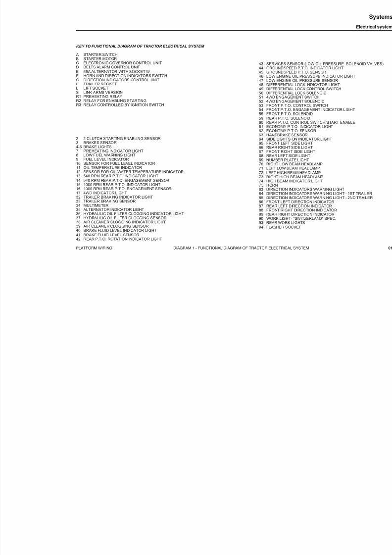
8/19/2019 Agrocompact f60 f70 f80 f90 Repair manual
http://slidepdf.com/reader/full/agrocompact-f60-f70-f80-f90-repair-manual 397/519
KEY TO FUNCTIONAL DIAGRAM OF TRACTOR ELECTRICAL SYSTEM
A STARTER SWITCHB STARTER MOTORC ELECTRONIC GOVERNOR CONTROL UNITD BELTS ALARM CONTROL UNITE 65A ALTERNATOR WITH SOCKET WF HORN AND DIRECTION INDICATORS SWITCHG DIRECTION INDICATORS CONTROL UNITI TRAILER SOCKETL LIFT SOCKETS LINK ARMS VERSIONR1 PREHEATING RELAYR2 RELAY FOR ENABLING STARTINGR3 RELAY CONTROLLED BY IGNITION SWITCH
2 2 CLUTCH STARTING ENABLING SENSOR3 BRAKES SENSOR4-5 BRAKE LIGHTS7 PREHEATING INDICATOR LIGHT8 LOW FUEL WARNING LIGHT9 FUEL LEVEL INDICATOR10 SENSOR FOR FUEL LEVEL INDICATOR11 OIL TEMPERATURE INDICATOR12 SENSOR FOR OIL/WATER TEMPERATURE INDICATOR13 540 RPM REAR P.T.O. INDICATOR LIGHT14 540 RPM REAR P.T.O. ENGAGEMENT SENSOR15 1000 RPM REAR P.T.O. INDICATOR LIGHT16 1000 RPM REAR P.T.O. ENGAGEMENT SENSOR17 4WD INDICATOR LIGHT32 TRAILER BRAKING INDICATOR LIGHT33 TRAILER BRAKING SENSOR34 MULTIMETER35 ALTERNATOR INDICATOR LIGHT36 HYDRAULIC OIL FILTER CLOGGING INDICATOR LIGHT37 HYDRAULIC OIL FILTER CLOGGING SENSOR38 AIR CLEANER CLOGGING INDICATOR LIGHT39 AIR CLEANER CLOGGING SENSOR40 BRAKE FLUID LEVEL INDICATOR LIGHT41 BRAKE FLUID LEVEL SENSOR42 REAR P.T.O. ROTATION INDICATOR LIGHT
43 SERVICES SENSOR (LOW OIL PRESSUR44 GROUNDSPEED P.T.O. INDICATOR LIGH45 GROUNDSPEED P.T.O. SENSOR46 LOW ENGINE OIL PRESSURE INDICAT47 LOW ENGINE OIL PRESSURE SENSOR48 DIFFERENTIAL LOCK INDICATOR LIGH49 DIFFERENTIAL LOCK CONTROL SWITC50 DIFFERENTIAL LOCK SOLENOID51 4WD ENGAGEMENT SWITCH52 4WD ENGAGEMENT SOLENOID53 FRONT P.T.O. CONTROL SWITCH54 FRONT P.T.O. ENGAGEMENT INDICATO55 FRONT P.T.O. SOLENOID59 REAR P.T.O. SOLENOID60 REAR P.T.O. CONTROL SWITCH/START61 ECONOMY P.T.O. INDICATOR LIGHT62 ECONOMY P.T.O. SENSOR63 HANDBRAKE SENSOR64 SIDE LIGHTS ON INDICATOR LIGHT65 FRONT LEFT SIDE LIGHT66 REAR RIGHT SIDE LIGHT67 FRONT RIGHT SIDE LIGHT68 REAR LEFT SIDE LIGHT69 NUMBER PLATE LIGHT70 RIGHT LOW BEAM HEADLAMP71 LEFT LOW BEAM HEADLAMP72 LEFT HIGH BEAM HEADLAMP73 RIGHT HIGH BEAM HEADLAMP74 HIGH BEAM INDICATOR LIGHT75 HORN83 DIRECTION INDICATORS WARNING LI84 DIRECTION INDICATORS WARNING LI85 DIRECTION INDICATORS WARNING LI86 FRONT LEFT DIRECTION INDICATOR87 REAR LEFT DIRECTION INDICATOR88 FRONT RIGHT DIRECTION INDICATOR89 REAR RIGHT DIRECTION INDICATOR90 WORK LIGHT- "SWITZERLAND" SPEC.93 REAR WORK LIGHTS94 FLASHER SOCKET
PLATFORM WIRING DIAGRAM 1 - FUNCTIONAL DIAGRAM OF TRACTOR ELECTRICAL SYSTEM
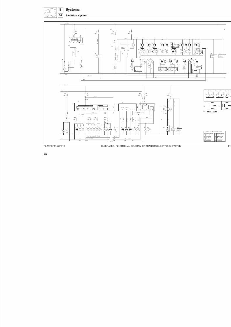
8/19/2019 Agrocompact f60 f70 f80 f90 Repair manual
http://slidepdf.com/reader/full/agrocompact-f60-f70-f80-f90-repair-manual 398/519

8/19/2019 Agrocompact f60 f70 f80 f90 Repair manual
http://slidepdf.com/reader/full/agrocompact-f60-f70-f80-f90-repair-manual 399/519
PLATFORM WIRING DIAGRAM 3 - CENTRAL WIRING FOR TRACTORS WITH ELECTRONIC GOVERNOR - 1ST VER
EV
PTO
HANDE BRAKE
V10
FRENO A MANO V.RUOTE
P4
SPEED
PTO SYNCRO
SYNCRO PTO
P2
P
5
TABELLA COLORI / COLOURS TABLE
Rosso/RedRosa/Pink Nero/Black Viola/Violet Verde/GreenMarrone/Brown
H
C
GLB A
Grigio/Gray Giallo/Yellow Blu/Dark BlueBianco/White Azzurro/Blue Arancio/Orange
3 2
4WDT
DOPPIA TRAZIONE
P3
H
EV H
H EV
L
L EV
EV L
SYNCRO
V12
SYNCRO
S
V13
II RISERVA
II EMPTY
V1425
4
26 29
1521
9
1 38
2014
TRAILER PRESS.
HAND BRAKEFRENO MANO
182021
1415
1617
9
13
12
EV DF
67
8
AL CENTRALETO CENTRAL
PTO 540PTO 1000ECONOMIC PTO
PTO 1000PTO 540
1234
A
PTO SYNCRO SYNCR O PTO
EV DT EV DTEV DF
VELOCITA'RUOTE SPEED VEL.RUOTE GND SPEED GND
EV PTO EV PTO
PTO ECONOMICA OIL FILTER/SERVICEF.OLIO/SERVICE5
PRESS.RIMORCHIO
GND GND
COM DT/DF/PTO COM DT/DF/PTO
22
10
G 1 AG 1
VB 1 VN 1
CN 1 AN 1H 1MV 1
MB 1RV 1HR 1GR 1
GV 1
N 1
G 1
N 1
G V 1
M V 1
H 1
N 1
X 1
A R 0 5
N 1
GV 1 X2
SPIA DT LIGHT DT11 AR05
Z B 1
M B 1
Z V 1
M B 1
EV HEV L
EV HEV L
ZV 1ZB 1
G 1
HN 1GALL RISERVA S PI A R ISE RVA EM PT Y L IGH T
EMPTY SENSORHM 1
H M 1
H N 1
N 1
H M 1
1 3 2
A MP
A MP
1 2 3
A M P
2 1
A M P
2 1
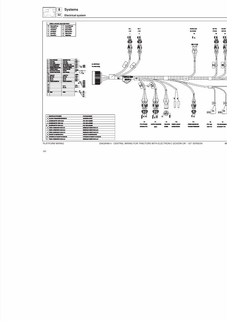
8/19/2019 Agrocompact f60 f70 f80 f90 Repair manual
http://slidepdf.com/reader/full/agrocompact-f60-f70-f80-f90-repair-manual 400/519
PLATFORM WIRING DIAGRAM 4 - CENTRAL WIRING FOR TRACTORS WITH ELECTRONIC GOVERNOR - 1ST VER
400
884
Systems
Electrical system
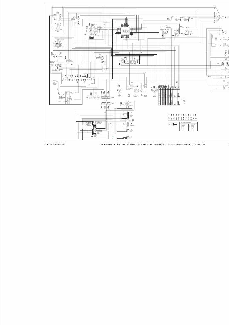
8/19/2019 Agrocompact f60 f70 f80 f90 Repair manual
http://slidepdf.com/reader/full/agrocompact-f60-f70-f80-f90-repair-manual 401/519

8/19/2019 Agrocompact f60 f70 f80 f90 Repair manual
http://slidepdf.com/reader/full/agrocompact-f60-f70-f80-f90-repair-manual 402/519
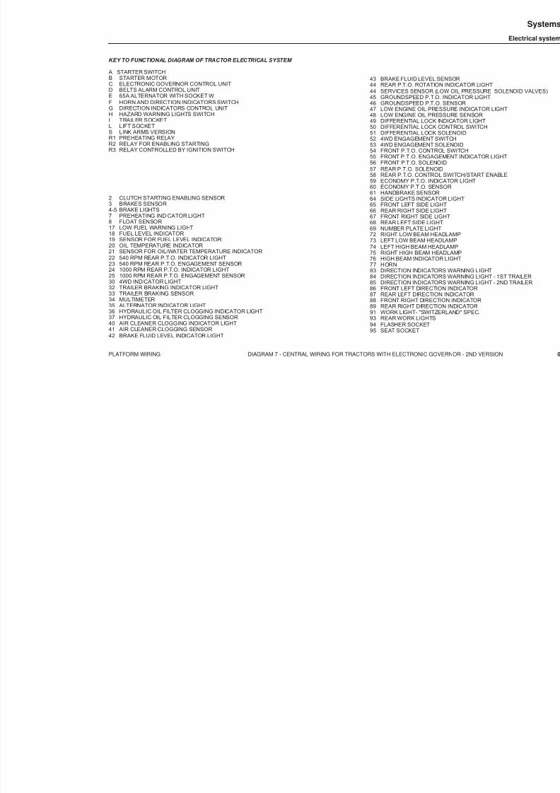
8/19/2019 Agrocompact f60 f70 f80 f90 Repair manual
http://slidepdf.com/reader/full/agrocompact-f60-f70-f80-f90-repair-manual 403/519
KEY TO FUNCTIONAL DIAGRAM OF TRACTOR ELECTRICAL SYSTEM
A STARTER SWITCHB STARTER MOTORC ELECTRONIC GOVERNOR CONTROL UNITD BELTS ALARM CONTROL UNITE 65A ALTERNATOR WITH SOCKET WF HORN AND DIRECTION INDICATORS SWITCHG DIRECTION INDICATORS CONTROL UNITH HAZARD WARNING LIGHTS SWITCHI TRAILER SOCKETL LIFT SOCKETS LINK ARMS VERSIONR1 PREHEATING RELAYR2 RELAY FOR ENABLING STARTINGR3 RELAY CONTROLLED BY IGNITION SWITCH
2 CLUTCH STARTING ENABLING SENSOR3 BRAKES SENSOR4-5 BRAKE LIGHTS7 PREHEATING INDICATOR LIGHT8 FLOAT SENSOR17 LOW FUEL WARNING LIGHT18 FUEL LEVEL INDICATOR19 SENSOR FOR FUEL LEVEL INDICATOR20 OIL TEMPERATURE INDICATOR21 SENSOR FOR OIL/WATER TEMPERATURE INDICATOR22 540 RPM REAR P.T.O. INDICATOR LIGHT23 540 RPM REAR P.T.O. ENGAGEMENT SENSOR24 1000 RPM REAR P.T.O. INDICATOR LIGHT25 1000 RPM REAR P.T.O. ENGAGEMENT SENSOR30 4WD INDICATOR LIGHT32 TRAILER BRAKING INDICATOR LIGHT33 TRAILER BRAKING SENSOR34 MULTIMETER35 ALTERNATOR INDICATOR LIGHT36 HYDRAULIC OIL FILTER CLOGGING INDICATOR LIGHT37 HYDRAULIC OIL FILTER CLOGGING SENSOR40 AIR CLEANER CLOGGING INDICATOR LIGHT41 AIR CLEANER CLOGGING SENSOR42 BRAKE FLUID LEVEL INDICATOR LIGHT
43 BRAKE FLUID LEVEL SENSOR44 REAR P.T.O. ROTATION INDICATOR LIG44 SERVICES SENSOR (LOW OIL PRESSUR45 GROUNDSPEED P.T.O. INDICATOR LIGH46 GROUNDSPEED P.T.O. SENSOR47 LOW ENGINE OIL PRESSURE INDICAT48 LOW ENGINE OIL PRESSURE SENSOR49 DIFFERENTIAL LOCK INDICATOR LIGH50 DIFFERENTIAL LOCK CONTROL SWITC51 DIFFERENTIAL LOCK SOLENOID52 4WD ENGAGEMENT SWITCH53 4WD ENGAGEMENT SOLENOID54 FRONT P.T.O. CONTROL SWITCH55 FRONT P.T.O. ENGAGEMENT INDICATO56 FRONT P.T.O. SOLENOID57 REAR P.T.O. SOLENOID58 REAR P.T.O. CONTROL SWITCH/START59 ECONOMY P.T.O. INDICATOR LIGHT60 ECONOMY P.T.O. SENSOR61 HANDBRAKE SENSOR64 SIDE LIGHTS INDICATOR LIGHT65 FRONT LEFT SIDE LIGHT66 REAR RIGHT SIDE LIGHT67 FRONT RIGHT SIDE LIGHT68 REAR LEFT SIDE LIGHT69 NUMBER PLATE LIGHT72 RIGHT LOW BEAM HEADLAMP73 LEFT LOW BEAM HEADLAMP74 LEFT HIGH BEAM HEADLAMP75 RIGHT HIGH BEAM HEADLAMP76 HIGH BEAM INDICATOR LIGHT77 HORN83 DIRECTION INDICATORS WARNING LI84 DIRECTION INDICATORS WARNING LI85 DIRECTION INDICATORS WARNING LI86 FRONT LEFT DIRECTION INDICATOR87 REAR LEFT DIRECTION INDICATOR88 FRONT RIGHT DIRECTION INDICATOR89 REAR RIGHT DIRECTION INDICATOR91 WORK LIGHT- "SWITZERLAND" SPEC.93 REAR WORK LIGHTS94 FLASHER SOCKET95 SEAT SOCKET
PLATFORM WIRING DIAGRAM 7 - CENTRAL WIRING FOR TRACTORS WITH ELECTRONIC GOVERNOR - 2ND VE

8/19/2019 Agrocompact f60 f70 f80 f90 Repair manual
http://slidepdf.com/reader/full/agrocompact-f60-f70-f80-f90-repair-manual 404/519
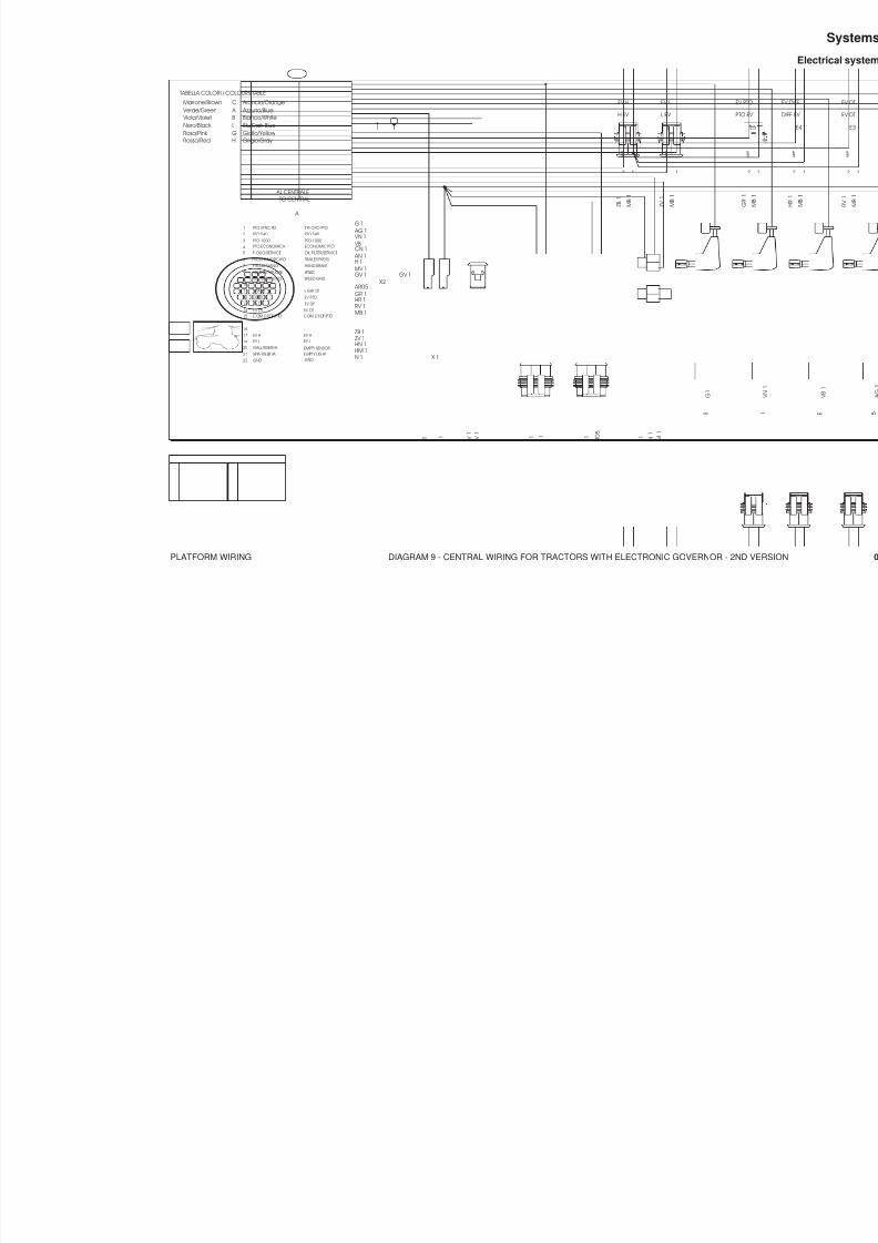
8/19/2019 Agrocompact f60 f70 f80 f90 Repair manual
http://slidepdf.com/reader/full/agrocompact-f60-f70-f80-f90-repair-manual 405/519
PLATFORM WIRING DIAGRAM 9 - CENTRAL WIRING FOR TRACTORS WITH ELECTRONIC GOVERNOR - 2ND VE
EV
PT
HANDE BRAKE
V10
FRENO A MANO V.RUOTE
P4
SPEED
PTO SYNCRO
SYNCRO PTO
P2
TABELLA COLORI / COLOURS TABLE
Rosso/RedRosa/Pink Nero/Black Viola/Violet Verde/GreenMarrone/Brown
H
C
GLB A
Grigio/Gray Giallo/Yellow Blu/Dark BlueBianco/White Azzurro/Blue Arancio/Orange
3 2
4WDT
DOPPIA TRAZIONE
P3
H
EV H
H EV
L
L EV
EV L
SYNCRO
V12
SYNCRO
S
V13
II RISERVA
II EMPTY
V1425
4
26 29
1521
9
1 38
2014
TRAILER PRESS.HAND BRAKEFRENO MANO
182021
1415
1617
9
1312
EV DF
678
AL CENTRALETO CENTRAL
PTO 540PTO 1000ECONOMIC PTO
PTO 1000PTO 540
123
4
A
PTO SYNC RO SYNCRO PTO
EV DT EV DTEV DF
VELOCITA'RUOTE SPEED VEL.RUOTE GND SPEED GND
EV PTO EV PTO
PTO ECONOMICA OIL FILTER/SERVICEF.OLIO/SERVICE5
PRESS.RIMORCHIO
GND GND
COM DT/DF/PTO COM DT/DF/PTO
22
10
G 1 AG 1
VB 1 VN 1
CN 1 AN 1H 1MV 1
MB 1RV 1HR 1
GR 1
GV 1
N 1
G 1
N 1
G V 1
M V 1
H 1
N 1
X 1
A R 0 5
N 1
GV 1 X2
SPIA DT LIGHT DT11 AR05
Z B 1
M B 1
Z V 1
M B 1
EV HEV L
EV HEV L ZV 1
ZB 1
G 1
HN 1GALL RISERVA SP IA R IS ERVA E MPT Y L IG HT
EMPTY SENSOR HM 1
H M 1
H N 1
N 1
H M 1
1 3 2
A MP
A MP
1 2 3
A M P
2 1
A M P
2 1

8/19/2019 Agrocompact f60 f70 f80 f90 Repair manual
http://slidepdf.com/reader/full/agrocompact-f60-f70-f80-f90-repair-manual 406/519
PLATFORM WIRING DIAGRAM 10 - CENTRAL WIRING FOR TRACTORS WITH ELECTRONIC GOVERNOR - 2ND VE
406
Systems
Electrical system
884
TRAILER PRESSURE
PRESS.RIMORCHIOFRENO A MANO
V10
HANDE BRAKESYNCRO PTO
PTO SYNCRO
P2 V11
FILTRO OLIO
V8
OIL FILTER
2 1
X2 X1 X4
To central wiring
AL CENTRALE
SEE NOTES
Targhetta di controlloCONTROL LABEL Vedi note
DOPPIA TRAZIONE
4WDT
P3 P4 VELOCITA'SPEED
X3
L EV
EV L
L H
H EV
EV H
X6
COLLEGAMENTO RISERVA II
II EMPTY
GALLEGGIANTEEMPTY SWITCH
-VCC+VCC
HM1
3 1 2
A MP
3 1 2 1 2
1
A MP
2
2 1 3
2 1 3
A MP
2 1
A M P
2
A M P
1
2 1 2 1
COM DT/DF/PTO
PRESS.RIMORCHIOF.OLIO/SERVICEPTO ECONOMICA
PTO SYNCRO
FRENO MANO
20
GND2221
EV PTO
EV DTEV DF
1718
16
15
1314
12
2 PTO 540PTO 1000
6
109
87
45
3
1
N 1
GR 1HR 1RV 1
GND
COM DT/DF/PTO
EV PTOEV DFEV DT
H 1 AN 1CN 1
VN 1 VB 1
AG 1G 1
PTO 540
OIL FILTER/SERVICEECONOMIC PTOPTO 1000
HAND BRAKETRAILER PRESS.
SYNCRO PTO
C N 1
N 1
N 1
G 1
H 1
N 1
A N 1
N 1
X3
HR-T 1
X1 N1
CN1CN1
X4
N1
T A P P O
T A P P O
N 1
A R 0 5
3 21
G V 0 8
V 1
MASSA VELOCITA'
VELOCITA' RUOTE
GND SPEED
SPEED V1GV08
N1N1
X2SPIA DT11 LIGHT DT
AR05
L H
Z V 1
R 1
R 1
Z B 1
ZV 1ZB 1EV H
EV LO
SPIA RISERVA GALL RISERVA I EMPTY SENS.1
EMPTY LIGHT
HN 1HM 1
G 1
G 1
X6
N1
COM EV H-L COM EV H-LR1
R1R1
TABELLA COLORI / COLOURS TABLE
Rosso/RedRosa/Pink Nero/Black Viola/Violet Verde/GreenMarrone/Brown
R
M
SNZ V
H
C
GLB A
Grigio/Gray Giallo/Yellow Blu/Dark BlueBianco/White Azzurro/Blue Arancio/Orange
HR-T 1HR-T 1HR-T 1

8/19/2019 Agrocompact f60 f70 f80 f90 Repair manual
http://slidepdf.com/reader/full/agrocompact-f60-f70-f80-f90-repair-manual 407/519
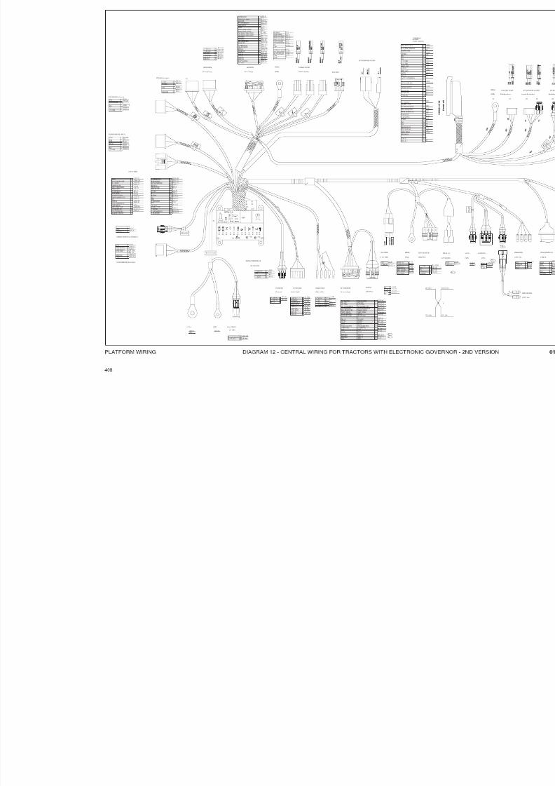
8/19/2019 Agrocompact f60 f70 f80 f90 Repair manual
http://slidepdf.com/reader/full/agrocompact-f60-f70-f80-f90-repair-manual 408/519
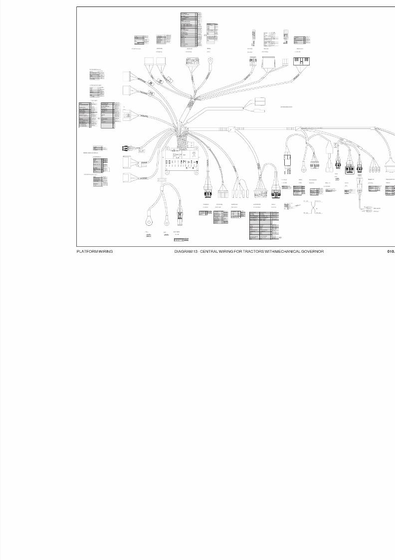
8/19/2019 Agrocompact f60 f70 f80 f90 Repair manual
http://slidepdf.com/reader/full/agrocompact-f60-f70-f80-f90-repair-manual 409/519

8/19/2019 Agrocompact f60 f70 f80 f90 Repair manual
http://slidepdf.com/reader/full/agrocompact-f60-f70-f80-f90-repair-manual 410/519
PLATFORMWIRING DIAGRAM14-REARLIGHTSWIRING(CODES:1STVERSIONWITHROLLBAR010.9058.3,WITHCA
410
Systems
Electrical system
884
SEE NOTES
Targhetta di controllo
CONTROL LABEL
Vedi note
Targhetta di controllo
Vedi noteSEE NOTES
CONTROL LABEL
TO UNDER-CARPET WIRING (LEFT) AL CABL.SOTTOTAPPETO (SX)
A
ALLA LUCE TARGATO PLAT LIGHT
I-3
TO UNDER-CARPET WIRING (RIGHT) AL CABL.SOTTOTAPPETO (DX)
A 1
GN 1
RN 1
G 1
N 1
TABELLA COLORI / COLOURS TABLE
Rosso/RedRosa/PinkNero/Black
Viola/VioletVerde/Green
Marrone/Brown
R
M
SN
ZV
H
C
GL
B A
Grigio/Gray
Giallo/YellowBlu/Dark Blue
Bianco/White Azzurro/Blue
Arancio/Orange
I-2 4
I-2 3
AN 1 B
G 1
N 1
G 1
B
A
B
( P O S I T I O N )
P O S
I Z I O N E
( C O N N E C T O R
C O N N E T T O R E
I-2
I-2
1
2
(TOTAL QUOTA)
QUOTATOTALE
RN 1
( C O N N E C T O R
C O N N E T T O R E
B
( P O S I T I O N )
P O S
I Z I O N E
G 1
AN 1
N 1
I-3 N 14
A 1 D
QUOTATOTALE
(TOTAL QUOTA)
( C O N N E C T O R
C O N N E T T O R E
I-3
I-3
I-3
3
2
1
P O S I Z I O N E
( P O S I T I O N )
C O N N E T T O R E
( C O N N E C T O R
GN 1
RN 1
D
D
( P O S I T I O N )
P O S I Z I O N E
S.U.2
S.U.3
D
3
1
2
AMP
3
2
1
4 4
I-2
RN 1
G 1
AN 1
N 1
N 1
1 1
AMP 2
4
3
4
2
3

8/19/2019 Agrocompact f60 f70 f80 f90 Repair manual
http://slidepdf.com/reader/full/agrocompact-f60-f70-f80-f90-repair-manual 411/519
PLATFORM WIRING DIAGRAM 15 - FRONT LIGHTS WIRING
8
7
4
6 GN 1
N 1
AN 1.5 A
3
1
CONN.AMP 070 P.M.COD.AMP 282370-1
CNT.AMP 2822378-1 (MASCHI)
N1
GN1
A N1 . 5
N1
G1
A 1 . 5
AL CABL.CENTRALE/SOTTOSTRUTTURA
TO CENTRAL/SUBSTRUCTURE WIRING
AI FANALINI ANTERIORI (SX)
TO FRONT-SIDE LIGHTS (LEFT)TO FRONT-SIDE LIGHTS (RIGHT)
AI FANALINI ANTERIORI (DX)
SPINE 5 AMP 140670
NASTRARE-BANDING
5 2

8/19/2019 Agrocompact f60 f70 f80 f90 Repair manual
http://slidepdf.com/reader/full/agrocompact-f60-f70-f80-f90-repair-manual 412/519
PLATFORM WIRING DIAGRAM 16 - HML CONTROL LEVER WIRING 2nd version equipped with pushbuttons code 2.7659.183.0
412
Systems
Electrical system
884
Z 0.5
H 0.5
B 0.5 Targhetta di controlloCONTROL LABEL
Vedi noteSEE NOTES
3
1
2 AMP
3
2
1
GUAINA-Scheat d.4

8/19/2019 Agrocompact f60 f70 f80 f90 Repair manual
http://slidepdf.com/reader/full/agrocompact-f60-f70-f80-f90-repair-manual 413/519
PLATFORM WIRING DIAGRAM 17 - HML WIRING (1ST VERSION)
TABELLA COLORI / COLOURS TABLE
Rosso/Red
Rosa/Pink Nero/Black
Viola/Violet Verde/GreenMarrone/Brown
R
M
SN
Z V
H
C
GL
B A
Grigio/Gray
Giallo/Yellow Blu/Dark Blue
Bianco/White Azzurro/Blue Arancio/Orange
T A R G H E T T A D I C O N T R O L L O
C o n t r o l l a b e l
V E D I N O T E
S e e n o t e s
Z-1 750
N 1 650Z-N 1 650 Z-B 1 650
M-B 1 530
Z-V 1 650
B 1 750
Z-N 1 1550 Z-B 1 1550
G U A I N A ( S h e a t h )
ø 7
Z
HB
H 1 750 X1
M B 1 530 M B 1 1030M B 1 120
M B 1 1030
X1
3 LEVA HI5 SPIA M6 +12 Vcc7 EV HI
12 LEVA LO13 LEVA COM.14 -Vcc15 EV LO
1
4
2
3
GTR.
8 7 6 5 43 2 1
M - B 1
1 2 0
Z - V 1 6 5 0
Z - B 1
6 5 0
Z - N 1 6 5 0
N 1 6 5 0
7
1 7
1 6
1 5
1 4
1 3
1 2
1 1
1 0
9
8
7
6
5
4
3
2
1
13 2
A M P
123

8/19/2019 Agrocompact f60 f70 f80 f90 Repair manual
http://slidepdf.com/reader/full/agrocompact-f60-f70-f80-f90-repair-manual 414/519
PLATFORM WIRING DIAGRAM 18 - HML WIRING (1ST VERSION)
414
Systems
Electrical system
884
TABELLA COLORI / COLOURS TABLE
Rosso/RedRosa/Pink Nero/Black Viola/Violet Verde/GreenMarrone/Brown
R
M
SNZ V
H
C
GLB A
Grigio/Gray Giallo/Yellow Blu/Dark BlueBianco/White Azzurro/Blue Arancio/Orange
Z 1 750
N 1 650
ZN 1 650 ZB 1 650MB 1 530
ZV 1 650
B 1 750
ZN 1 1550 ZB 1 1550
H 1 750
1
H/M
L
2 34 5 6 7 8
N 1 6 5 0
Z B 1 6
5 0
Z N 1 6 5 0
Z V 1 6 5 0
M B 1 1 2 0
SUBSTR.WIRING
CABL.SOTTOSTR.
X1
1 7
1 6
1 5
1 4
1 3
1 2
1 1
1 0
9
8
7
6
5
4
3
2
1
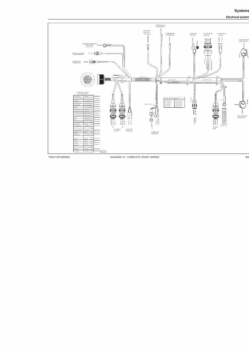
8/19/2019 Agrocompact f60 f70 f80 f90 Repair manual
http://slidepdf.com/reader/full/agrocompact-f60-f70-f80-f90-repair-manual 415/519
TRACTOR WIRING DIAGRAM 19 - COMPLETE FRONT WIRING
P T OA N T .
DIPPED HEAD LIGHTS
DIPPED HEAD LIGHTS
FULL BEAM HEAD LIGHTS
HORN
RPM INDICATOR
GENERATOR
TEMPERATURE
ENGINE OIL PRESS.
AIR FILTER
ANABBAGL.
ANABBAGL.
ABBAGLIANTI
AVV. ACUSTICO
W CONTAGIRI
GENERATORE
TEMPERAT.
P. OLIO MOT.
FILTRO ARIA
GENERATORE
1
2
3
4
5
6
7
8
B 1 1600
9
10
11
12
13
14
15
M 1 1300
R 1 1350
L 1 1700
BR 1 1700
Z 1 1350
V 1 1600
H 1 1600
HN 1 1600 N 1 1 4 0 0
MN 1 1 3 5 0
FILTRO ARIA
N 1 1 6 0 0
B 1
1 6 0 0
F R ON T P T O
GENERATOR
AIR FILTER
AL CABLAGGIO CENTRALETO CENTRAL WIRING
N 16 2050MOTORINO AVVIAMENTO
START ENGINE(OCCH.ø 10)
BRAKES OILOLIO FRENI
FULL BEAM HEAD LIGHTS ABBAGLIANTI V 1 1600
CANDELETTA PLUG RN 1.5 1150
RN 1.5 1150PLUG CANDELETTA
ELECKTROVALVE ELETTROVALVOLA BN 1 1250
F RO NT P TO P TO A NT. MN 1 1350
COMPRESS.COMPRESSOR VN 1.5 1150
16
RPM FAN
BRAKES OIL
+12 VOLT
RPM VENT.
OLIO FRENI
+12 VOLT MB 1 100
HB 1 175028
29
20 ZN 1 1750
L 1 1 7 0 0
( D +
)
B R 1 1 7 0 0 ( W )
N 1 6 2 0 5 0
( B + )
ELETTROVALVOLA ELCKTROVALVE
B N 1 1 2 5 0
V N 1 . 5 1 1 5 0
COMPRESSOR
2 x R N 1 . 5 1 1 5 0
CANDELETTA START PLUG
M 1 1300
R 1 1350
N 1 2 1 5 0
Z N 1 7 5 0
ENGINE PRESSUREPRESS.OLIO MOTORE
TEMPERATURETEMPERATURA
GUAINA IN PVC øi 12
G U A I N A I N P V C ø i 4
G U A I N A I N P V C ø i 4
GUAINA IN PVC øi 14
G U A I N A I N P V C ø i 7
CORRUGATO ø 17
CORRUGATO ø 6.7
C O R R U G A T O ø 1 0
(OCCH.ø 5.2)
GUAINA IN PVC øi 5
G.T.R.G.T.R. G.T.R.
TABELLA COLORI / COLOURS TABLE
Rosso/Red
Rosa/Pink Nero/Black
Viola/Violet Verde/Green
Marrone/Brown
R
M
SN
Z V
H
C
GL
B A
Grigio/Gray
Giallo/Yellow Blu/Dark Blue
Bianco/White Azzurro/Blue
Arancio/Orange
G . T . R .
G U A I N A I N P V C ø i 6
G.T.R. L=30
GALLEGGIAFuel level
C
1 1 2 5 0
H N 1 1 2 5 0
N
1 1 3 5 0
GALLEGGIANTE Fuel level 17
RISERVA reserve 18 HN 1 1250
C 1 1250
MB 1 1700
MB 1 1200
COMPRESSORE
G U A I N A I N P V C ø i 6
LIGHT L
DIRECT. L
DIREZ. DX
POS. DX
DIREZ. SX
P OSI Z. SX 2 1
22
23
24 A 1 250
G 1 250
AN 1 450
GN 1 450
LIGHT R
DIRECT. R
A N 1 4 5 0
GN 1 4 5 0
N 1 2 3 5 0
N 1 2 1 5 0
G1 2 5 0
A 1 2 5 0
GUAINA IN PVC øi
G.T.R.
C A P P U C C I O
C A P P U C C I O
1
9
2621
15
414
2925
20
38
SEE NOTES
Targhetta di controlloCONTROL LABEL
Vedi note
AI FANALINITO LIGHT
DX SX
1 2
A MP
1 A M P
3 24
A M P
1 3 2
A MP
1 2
1 3 2
A MP
2 3

8/19/2019 Agrocompact f60 f70 f80 f90 Repair manual
http://slidepdf.com/reader/full/agrocompact-f60-f70-f80-f90-repair-manual 416/519
TRACTOR WIRING DIAGRAM 20 - COMPLETE FRONT WIRING
416
Systems
Electrical system
884
PTO ANT.
DIPPED HEAD LIGHTS
DIPPED HEAD LIGHTS
FULL BEAM HEAD LIGHTS
HORN
RPM INDICATOR
GENERATOR
TEMPERATURE
ENGINE OIL PRESS.
AIR FILTER
ANABBAGL.
ANABBAGL.
ABBAGLIANTI
AVV. ACUSTICO
W CONTAGIRI
GENERATORE
TEMPERAT.
P. OLIO MOT.
FILTRO ARIA
GENERATORE
1
2
3
4
5
6
7
8
B 1
A
9
10
11
12
13
14
15
M 1
R 1
L 1
BR 1
Z 1
V 1
H 1
HN 1
N 1
MN 1
FILTRO A
N 1
B 1
FRONT PTO
GENERATOR AIR FILT
AL CABLAGGIO CENTRALETO CENTRAL WIRING
1
9
2621
15
414
2925
20
38 N
1 6
MOTORINO AVVIAMENTOSTART ENGINE
(OCCH.ø 10)
BRAKES OILOLIO FRENI
FULL BEAM HEAD LIGHTS ABBAGLIANTI V 1
CANDELATTA PLUG RN 1.5
RN 1.5PLUG CANDELATTA
ELECKTROVALVE ELETTROVALVOLA BN 1
FRONT PTO PTO ANT. MN 1
COMPRESS.COMPRESSOR VN 1.5
LIGHT L
BRAKES OIL
DIRECT. R
POSIZ. SX
OLIO FRENI
DIREZ. SX
MB 1
HB 1
21
22
20 ZN 1
L 1
B R 1
N 1 6
ELETTROVALVOLA ELCKTROVALVE
B N 1
V N 1 . 5
COMPRESSORECOMPRESSOR
R N 1
. 5
CANDELETTA START PLUG
M1
R 1
N 1
Z N 1
H B 1
N 1
MB 1
ENGINE PRESSUREPRESS.OLIO MOTORE
TEMPERATURETEMPERATURA
B
C
D
E
F G
H
I
L
P T
(OCCH.ø 5.2)
R N 1
. 5
VENTOLEFANS
Fuel level
ReserveRISERVA
GALLEGGIANTE
18
17
H N 1
N 1
MB 1
C1
MB 1
MB 1
C 1
HN 1
FUEL LEVELGALLEGGIANTE
I
RPM FAN
+12 VOLT +12 VOLT
RPM VENT. 28
29
23
24DIREZ. DX
POSIZ. DXLIGHT R
DIRECT. L
FANALINILIGHT
L2
GN 1
N 1
A N 1
SX
G 1
AN 1
GN 1
A 1
FANALINILIGHT
SX L2
N 1
G1
A 1
1 2
A MP
1 3 2
A MP
1
A M P
1 3 2 4
A MP
A MP
2 1 3 1
A MP
2 3

8/19/2019 Agrocompact f60 f70 f80 f90 Repair manual
http://slidepdf.com/reader/full/agrocompact-f60-f70-f80-f90-repair-manual 417/519
TRACTOR WIRING DIAGRAM 21 - BATTERY WIRING
MORSETTO POSITIVO BATTERIA (POSITIVE BATTERY)
TERMINALE INTEGRALE ø 10.5 (INTEGRAL CONT.)
MORSETTO NEGATIVO BATTERIA (NEGATIVE BATTERY)

8/19/2019 Agrocompact f60 f70 f80 f90 Repair manual
http://slidepdf.com/reader/full/agrocompact-f60-f70-f80-f90-repair-manual 418/519
TRACTOR WIRING DIAGRAM 22 - POWER LIFT WIRING
418
Systems
Electrical system
884
A M P
A M P
6
1
5
2
4
3
123 3
2
1
A M P
3
2
1
A M P
1
2
3 A M P
A M P
3
2
1
5
4
321
A MP
A M P
3 2 1
AMP4
5
6
1
2
3
1 2 21 3
4 6532 7 98 10 11 121
M A X
A L Z A T A
V E L . D I S C E S A
M I X
P O S I Z I O N E
I S O 9 1 4 1
+ 1 2
V C C
CENTRALINA SOLLEVATORE
M A S S I M A
V E L O C I T A '
R E G O L A Z I O N E
A L Z A T A
D I S C E S A
M I X
AL CARRO
C O M A N D O
U P - D W
R E G O L A Z I O N E
P O S I Z I O N E
ALIMENTAZI
AL SOTTOST.
VARIANTE
STEGOLI
C1
H
V
P 2
M
P 1
A1 A2
C
N 1
M 1
B N 1
A B 1 B 1 A N
1
H05
L05
M05
N05
M05
N05
M05
N05
S05
M05
N05
V05
MB1
M1
HR1
L05
S05
M B 1
H R 1
V 0 5 S 0 5
H 0 5
L 0 5
B N 1
N 1
A B 1
N 1
N 1
A B 1 A N 1
B N 1
N 1 M
1 B 1
G N D
+ 1 0 V C C
P O S I Z I O N E
S F O R Z O
E V U P
E V D
W
AB1
AN1
BN1
N1
M1
B1
ALZATA
UP
EV UP
DW
EV DW
P3
POSIZIONE
S
SFORZO
A N 1
M 1
M 1
N 1
B 1
C2
1 3221
1 5 0 1 5 0
H
V
M
P
N 1
M B 1
N 1
M B 1
H R 1
X2 X4 X5
X1 X3
X6 X7
D W
U P P S
1 2
1
7
6
X9
X10
X8
S E E N OT E S
T ar gh et t a d i c ont r ol l o
C ON T R OL L A B E L
V e d i n ot e
TABELLA COLORI / COLOURS TABLE
Rosso/Red
Rosa/Pink
Nero/Black
Viola/Violet
Verde/Green
Marrone/Brown
R
M
S
N
Z
V
H
C
G
L
B
A
Grigio/Gray
Giallo/Yellow
Blu/Dark Blue
Bianco/White
Azzurro/Blue
Arancio/Orange
F.to A2

8/19/2019 Agrocompact f60 f70 f80 f90 Repair manual
http://slidepdf.com/reader/full/agrocompact-f60-f70-f80-f90-repair-manual 419/519
TRACTOR WIRING DIAGRAM 23 - POWER LIFT WIRING
A MP
A M P
A MP
A MP
A MP
A MP
A MP
A M P
6 15 24 3123 321 321 1 2 3 321 54 3213 2 1
46 5 3 2 7 9 8 10 11 12 1
P O S I Z I O N E
+ 1 0 V C C
E V D W
G N D
S F O R Z O
E V U P
M A X A L Z A T A
V E L . D I S C E S A
M I X
P O S I Z I O N E
I S O 9 1 4 1
+ 1 2 V C C
CENTRALINA SOLLEVATORE
MA SSIMA VELOCITA' REGOLAZIONE
ALZATA DISCESA MIX AL CARRO
COMANDO
UP-DW
REGOLAZIONE
POSIZIONE
ALIMENTAZIONE
AL SOTTOST. VARIANTE
STEGOLI
M A X A L Z A T A
V E L . D I S C E S A
M I X
P O S I Z I O N E
I S O 9 1 4 1
+ 1 2 V C C
G N D
G N D
G N D
G N D
D W
G N D
+ 1 0 V C C
+ 1 0 V C C
+ 1 0 V C C
+ 1 0 V C C
+ 1 0 V C C
G N D
+ 1 2 V C C
I S O 9 1 4 1
C O M U N E
U P
C1
H V P2M P1
A1
A2
C
N 1
M 1
B N 1
A V 1
B 1 A N 1
H 0 5
V 0 5 M 0 5
N 0 5
M 0 5
N 0 5
M 0 5
N 0 5
S 0 5 M 0 5
N 0 5
L 1 H R 1
L 0 5
M 1
H R 1
N 1
M 1
N 1 M
B 1 M B 1
N 1
M B 1
H R 1
L 1 S 0 5 H 0 5
V 0 5
A V 1
A N 1
B N 1
N 1
M 1
B 1
G N D
+ 1 0 V C C
P O S I Z I O N E
S F O R Z O
E V U P
E V D W
X1
X2
X3 X4
X5

8/19/2019 Agrocompact f60 f70 f80 f90 Repair manual
http://slidepdf.com/reader/full/agrocompact-f60-f70-f80-f90-repair-manual 420/519
TRACTOR WIRING DIAGRAM 24 - STABILISERS AND RH LIFT ROD ADJUSTMENT WIRING
420
Systems
Electrical system
884
TABELLA COLORI / COLOURS TABLE
Rosso/RedRosa/PinkNero/BlackViola/VioletVerde/GreenMarrone/Brown
R
M
SNZV
H
C
GLB A
Grigio/GrayGiallo/YellowBlu/Dark BlueBianco/White Azzurro/Blue Arancio/Orange
1
2
4
3
5
1 AMP
2
1
2
4
3
5
1
2
4
3
5 L1HN1H1RV1L1
C1Z1M1RV1M1
L1G1H1RV1V1
G 1
N 1
M 1
N 1
C 1
N 1
Z 1
N 1
N1.5
RV1.5
1
2
ALIMENTAZIONE
G1G1V1V1GV1
CONN.SUPERSEALAMP 2 VIE P.F.
RV1.5
X1
RV1RV1
RV1
RV1
N1.5
X2
N1
N1
N1
N1
N1
X3
N1
N1
N1
N1
X5
M1M1
M1
M1
L1X6
L1
L1
L1
H1X7
H1
H1
N1
N1
HN1
HN1
EV4EV1EV6EV7
T
1 6 7 4 2
1 2
1
A MP
2
1 2
1
A MP
2
1 2
1
A MP
2
1 2
1
A MP
2
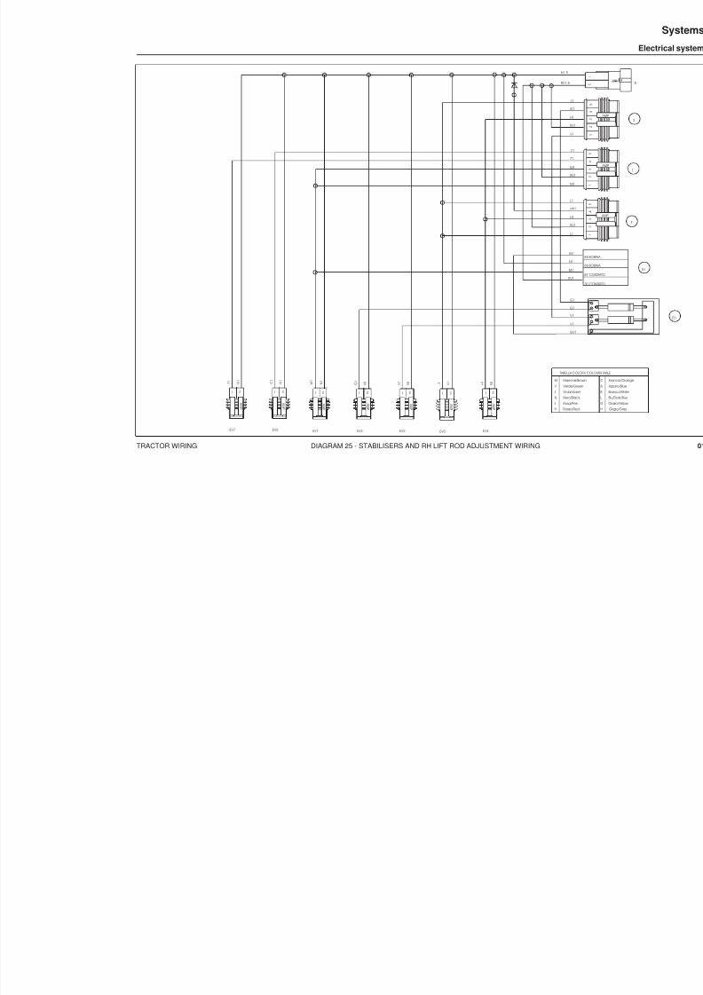
8/19/2019 Agrocompact f60 f70 f80 f90 Repair manual
http://slidepdf.com/reader/full/agrocompact-f60-f70-f80-f90-repair-manual 421/519
TRACTOR WIRING DIAGRAM 25 - STABILISERS AND RH LIFT ROD ADJUSTMENT WIRING
EV3EV5EV2EV4EV1EV6EV7
TABELLA COLORI / CO
Rosso/Red
Rosa/Pink
Nero/Black
Viola/Violet
Verde/Green
Marrone/Brown
R
M
S
N
Z
V H 1
N 1
1
2
4
3
5
1
2
1
2
4
3
5
1
2
4
3
5 L1
HN1
H1
RV1
L1
C1
Z1
M1
RV1
M1
L1
G1
H1
RV1
V1
L 1 N 1 V
1 N 1
G 1
N 1 M
1 N 1
C 1
N 1
Z 1 N 1
N1.5
RV1.5
G1
G1
V1
V1
GV1
GV1
N1
M1
RV1
1
A MP
2 1
A MP
2 1
A MP
2 1
A MP
2 1
A MP
2 1
A MP
2 1
A MP
2
85 BOB
86 BOB
30 CON
87 CON
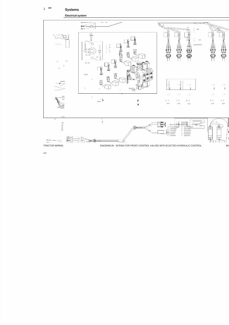
8/19/2019 Agrocompact f60 f70 f80 f90 Repair manual
http://slidepdf.com/reader/full/agrocompact-f60-f70-f80-f90-repair-manual 422/519
TRACTOR WIRING DIAGRAM 26 - WIRING FOR FRONT CONTROL VALVES WITH ELECTRO-HYDRAULIC CONTR
422
884
EV3A EV2A EV1A
5
5
6 6
34
12
1 2 3
TABELLA COLORI / COLOURS TABLE
Rosso/RedRosa/Pink Nero/Black Viola/Violet Verde/GreenMarrone/Brown
R
M
SNZ V
H
C
GLB A
Grigio/Gray Giallo/Yellow Blu/Dark BlueBianco/White Azzurro/Blue Arancio/Orange
M 1
N 1
C 1
N 1
Z 1 N 1
Z1
G1
C1
V1
RV1
M1
RV1
L1
N1.5
RV1.5
1A
1B
2A
2B
+
RV1-100
RV1-100
RV1-100
1
3
2
4
Z1
G1
C1
V1
ROSSO
GIALLO
RV1-100
1 2
1
A MP
2
1 2
1
A MP
2
1 2
1
A MP
2
1
A MP
2
1
A MP
2
1
A MP
2
1 2
1
A MP
2
A MP
1
A MP
2
RV1.5
X2
RV1
RV1
N1N1
N1
X1
N1
N1N1
N1.5
RV1
RV1
RV1
Systems
Electrical system

8/19/2019 Agrocompact f60 f70 f80 f90 Repair manual
http://slidepdf.com/reader/full/agrocompact-f60-f70-f80-f90-repair-manual 423/519
TRACTOR WIRING DIAGRAM 27 - WIRING FOR FRONT CONTROL VALVES WITH ELECTRO-HYDRAULIC CONT
EV4REV6REV5REV4GEV6GEV5G
L 1 N 1 V
1 N 1
G 1
N 1
M 1
N 1 C
1 N 1
Z 1 N 1
1
A MP
2 1
A MP
2 1
A MP
2 1
A MP
2 1
A MP
2 1
A MP
2

8/19/2019 Agrocompact f60 f70 f80 f90 Repair manual
http://slidepdf.com/reader/full/agrocompact-f60-f70-f80-f90-repair-manual 424/519
TRACTOR WIRING DIAGRAM 28 - CAB ROOF WIRING
424
Systems
Electrical system
884
1 23
4 3
2 1
2 4
1 3
1
2
S E E N O T E S
T a r g h e t t a d i c o n t r o l l o
C O N T R O L L A B E L V e d i n o t e
31 2 541 32
8 5
8 6 8
7
3 0
M - G
1 . 5
G - V 1 .
5
A 1
R 4
A - N 2 . 5
M R
1
R 1 .
5
M 2.5-150
M 2.5-200
LB 1
15
2 3 46 7 8
A-N 2.5
V 1
N 2.5
HV 1
F1
C
62
51
73
84
R 2.5
V 1
A - N 1
M - G 1 . 5
N
1
G 1
. 5
G 1
8 0
H - N
1
H - N
1 8 0
C 1
A 1
8 0
G - V
1 . 5
N
1
G - N
1
G N 1
8 0
M R
1 . 5 N 1
T1
N 1 V 1 V-N 1.5HV 1
R 4
N 4
R 2.5
N 1N 1
N 2.5N 4N 1 N 1
INT. FARI LAVORO ANTERIORIFront side work light switch
MASSA Ground
INT. TERGI ANTERIOREFront side glass washer switch
Rear side glass washer switchINT. TERGI POSTERIORE
Flash light switchINTERUTTORE LAMP
AL CAB. FARI LAVOROTERGI POST. LAMPEGGIANTETo wiring work lightglass washer flash light
To wiring air conditioner AL CABlAGGIO CONDIZIONATORE
CONDIZIONAMENTO BORLETTI AL GRUPPO RISCALDAMENTO
AL TERGI ANTERIORE
To glass washer
To group Borletti airconditioner end heating
1
A H
8
N 1
POSIZIONE FISSAGGIO RELE' RR rele' position fixing
FISSAGGIO RELE' CONDIZIONATORE
Rele' co nditioner fixing
Rear side work light switch
INT. FARI LAVORO POSTERIORI
A - N 1
N 1N 1
L-B 1
V-N 1.5D1
P.Supply ALIMENTAZIONE
R - N 1
H 1
R 1
V - N 1
N 1
G - R 1
A - N 1
T3
R 1N 1PLAFONIERA
Roff lamp
G 1
G 1
GN 1
GN 1
M 1,5
H-N 1
AR 1
C 1
R 1
G - N
1
N 1
R1
VN macc. 0.8
V N m a c c . 0
. 8
R 1
H 1
N 1
G R 1
V N 1
V 1 R N 1
OROLOGIO DIGITALEDIGITAL WATCH
A - N 1
( 3 1 ) ( 5 3 )
( 5 3 A a )
( 3 1 b )
1 0 9 3
4
7
8
2 6
1 5
2
1
TO BACK-SIDE WIPER E.C.U. ALLA CENTRALINA TERGI POST.
4 3 2 1
A1
R 1
N 1
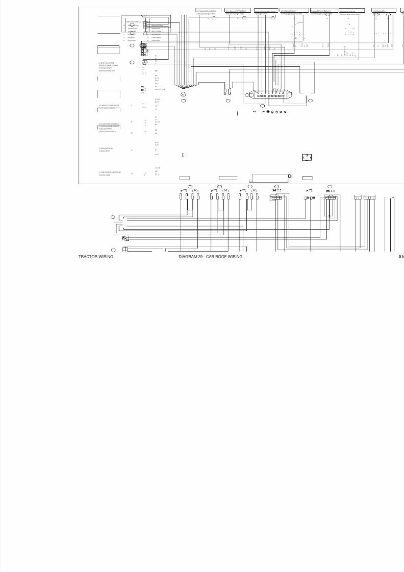
8/19/2019 Agrocompact f60 f70 f80 f90 Repair manual
http://slidepdf.com/reader/full/agrocompact-f60-f70-f80-f90-repair-manual 425/519
TRACTOR WIRING DIAGRAM 29 - CAB ROOF WIRING
1 23
R 1 R 1 R 1 . 5
R 1 . 5
G - V 1 . 5
M - G
1 . 5
A 1
A - N 1
G - V 1 .
5
R 2.5 M 2.5
M 2.5
M R
1
A-N 2.5
A - N - 2 . 5
R4
R 4
A-N 1
N 2.5
HV 1
V1
N1
V1
HV 1 V-N 1.5
N 1
N1
V-N 1
G-R 1
M 1 . 5
M 1 . 5
G - N
1
G - N
1
G 1
G 1
N4
L-B 1
V-N 1.5
N 1
N 2 . 5
N 4
N 1
A - N 1
A - R 1
L B 1
N 1
N 1
N 1
N 1
N 1
N 1
N 1
A - N 1
N 1
R 2.5
MR 1
C1
AR 1G 1
G 1
M 1.5GN 1
GN 1
HN 1
N 1
R 1
A - N 1
A - N 1
+
0
I N T
N 1
V 1 H 1 R N 1
1
R 1
N 1
A 1
4 3
2 1
2 4
1 3
1
2
8 5 8 6
87
30
62
51
73
84
P L
R
A
F
M G
INT. FARI LAVORO ANTERIORI
Front side work light switch
MASSA
Ground
INT. TERGI ANTERIORE
Front side glass washer switch Re
INFlash light switchINTERUTTORE LAMPEGGIANTE
AL CAB. FARI LAVOROTERGI POST. LAMPEGGIANTE
To wiring work light
glass washer flash light
To wiring air conditioner
AL CABlAGGIO CONDIZIONATORE
PLAFONIERA Roff lamp
CONDIZIONAMENTO BORLETTI AL GRUPPO RISCALDAMENTO
AL TERGI ANTERIORETo glass washer
To group Borletti air
conditioner end heating
1
A H
8
Rear side work light switch
INT. FARI LAVORO POSTERIORI
To power supply
AL CABLAGGIO ALIMENTAZIONE
RELE'
F1
C
B
B1
T3
D1
T
F
VN macc. 0.8
R1
Front side glass washer switch
PULSANTE POMPA TERGI ANT.
T2
1 0 A
1 0 A
5 A
R A D I O
3 0 A
7 . 5 A
2 0 A
7 . 5 A
1 0 A
1 0 9 3
4
7
8
2 6
1 5
2
1
TABELLA COLORI / COLOURS TABLE
Rosso/Red
Rosa/Pink
Nero/Black
Viola/Violet
Verde/Green
Marrone/Brown
R
M
S
N
Z
V
H
C
G
L
B
A
Grigio/Gray
Giallo/Yellow
Blu/Dark Blue
Bianco/White
Azzurro/Blue
Arancio/Orange

8/19/2019 Agrocompact f60 f70 f80 f90 Repair manual
http://slidepdf.com/reader/full/agrocompact-f60-f70-f80-f90-repair-manual 426/519
TRACTOR WIRING DIAGRAM 30 - CAB ROOF WIRING
426
Systems
Electrical system
884
R2.5
2xM2.5
R6
LB
+12VCC
+12VCC
CH 15
R1
F1
10A
R
F2
5A
M
F3
30A
A N
5
F4
20A
2
7 R
F5
7.5A
3 4
7 8
AN
A R
1 2
5 6
11
G
1 2 4 3
D+ D-
L BGR
1
NL
2 4 31
8
9
V V N
+12V
4
6
A CR
M
1
2
3
HV
B+ B-
10
M
12
P
13
R V N
A N
B A R
15
R
3 2 1 5 4 13 2
V R G V H
N N R N
AN
H
22
TABELLA COLORI / COLOURS TABLE
Rosso/Red
Rosa/Pink
Nero/Black
Viola/Violet
Verde/Green
Marrone/Brown
R
M
S
N
Z
V
H
C
G
L
B
A
Grigio/Gray
Giallo/Yellow
Blu/Dark Blue
Bianco/White
Azzurro/Blue
Arancio/Orange
(53)
(31)
(31b)
(53a)

8/19/2019 Agrocompact f60 f70 f80 f90 Repair manual
http://slidepdf.com/reader/full/agrocompact-f60-f70-f80-f90-repair-manual 427/519
TRACTOR WIRING DIAGRAM 31 - WORK LIGHTS AND SCREEN WIPER WIRING
N 1 .5
G 1 . 5
G 1 .5
N 1 .5
G N 1 .5
N 1 .5
G N 1 . 5
N 1. 5
AI FARI DI LAVORO ANTERIORI
To front side work light
To rear side work light
AI FARI DI LAVORO POSTERIORI
To rear side glass washer
AL TERGI POSTERIORE ALLE POMPE TERGI
To pump glass washer
N 1 . 5
M 1. 5
AL LAMPEGGIANTE
To flash light
A R 1
N 1
N 1 C
1 N 1
N 1
H-N 1
V1
R1
SEE NOTES Vedi note
(+AZZ)
(AZZ.)
(+MOT)
(GND)
T
R
M
S
N
Z
V
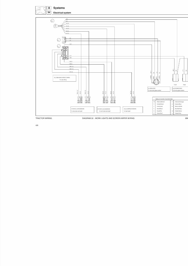
8/19/2019 Agrocompact f60 f70 f80 f90 Repair manual
http://slidepdf.com/reader/full/agrocompact-f60-f70-f80-f90-repair-manual 428/519
TRACTOR WIRING DIAGRAM 32 - WORK LIGHTS AND SCREEN WIPER WIRING
428
Systems
Electrical system
884
To rear side work light
AI FARI DI LAV.POSTERIORI
To rear side glass wash
AL TERGI POST.
ALLA LAMPADA ROTANTE
To flash light
To cab wiring
AL CABLAGGIO AEREO CABINA
G N 1
, 5
N 1
, 5
G N 1
, 5
N 1
, 5
G 1
, 5
N 1
, 5
G 1
, 5
N 1
, 5
AI FARI DI LAV.ANTERIORI
To front side work light
N 1
, 5
M 1
, 5
G1,5
G1,5GN 1,5
GN 1,5
M 1,5
HV 1
H V 1
AR 1
C 1
N1
N1,5
N1,5
N1,5
N1,5
N1,5
N1
N 1
M
F1
V1
R1
F2
V 1
TABEL
Ross
Rosa
Nero
Viol
Verd
Marr
R
M
S
N
Z
V
4
3
1 0 9
7
8
1
2
5
6
2
1
( A Z Z )
( + M O T )
( G N D )

8/19/2019 Agrocompact f60 f70 f80 f90 Repair manual
http://slidepdf.com/reader/full/agrocompact-f60-f70-f80-f90-repair-manual 429/519
TRACTOR WIRING DIAGRAM 33 - WINDSCREEN WIPER WIRING
V-N 1
R-N 1 G-R 1
M-N 1
FORNIRE SCIOLTI
Free (not connect)
CONN. AMP M-L 4 VIE P.F.
COD. AMP 0-925076-0
(+MOT)
(GND)(AZZ.)
(+AZZ)
AL TERGI ANTERIORE
To front glass wiper
CA. AMP163300-2
CABLAGGIO
WIRES
CORRISPONDENZA
GUAINA (SHEATH) ø 7
TERM. AMP. 163301-2
AMP 0-925075-0
P.M. M-L 4V IE-WIRES
TABELLA COLORI / COLOURS TABLE
Rosso/RedRosa/Pink Nero/Black Viola/Violet Verde/GreenMarrone/Brown
R
M
SNZ V
H
C
GLB A
Grigio/Gray Giallo/Yellow Blu/Dark BlueBianco/White Azzurro/Blue Arancio/Orange

8/19/2019 Agrocompact f60 f70 f80 f90 Repair manual
http://slidepdf.com/reader/full/agrocompact-f60-f70-f80-f90-repair-manual 430/519
TRACTOR WIRING DIAGRAM 34 - ELECTRIC HEATING WIRING
430
Systems
Electrical system
884
N 16
N 16
A L G R U P P O R I S C A L D A M
E N T O
T o H e a t i n g G r o u p
1
N 16N-L 1
5
L 1N 16
N 16
N 16
N 16
N 16
13
16
Targhetta di controlloCONTROL LABEL
Vedi noteSEE NOTES
B 1G-R 1
B 1
N-L 1G-R 1
L 1
B 1
L 1G-R 1
N-L 1
B 1
L 1G-R 1N-L 1
3
4
1
2
AMP
1
2
2
1
AMP 2
1
1
3
2
4
A M P
2
1
3
4
3
1
2 A M P
3
2
1
4 4
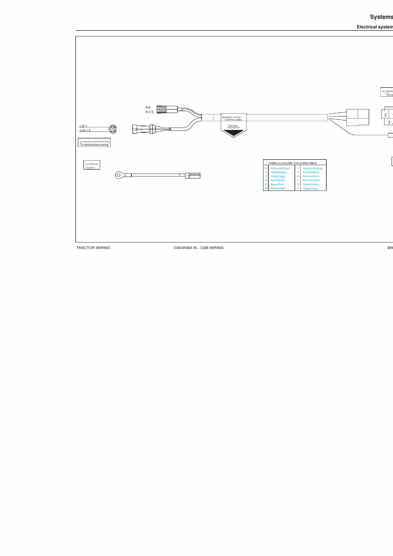
8/19/2019 Agrocompact f60 f70 f80 f90 Repair manual
http://slidepdf.com/reader/full/agrocompact-f60-f70-f80-f90-repair-manual 431/519
TRACTOR WIRING DIAGRAM 35 - CAB WIRING
L B 1V-N 1.5
TABELLA COLORI / COLOURS TABLE
Rosso/RedRosa/PinkNero/BlackViola/VioletVerde/GreenMarrone/Brown
R
M
SNZV
H
C
GLB A
Grigio/GrayGiallo/YellowBlu/Dark BlueBianco/White Azzurro/Blue Arancio/OrangeTo positive
AL POSITIVO
AL CABLAGGIO SOTTOSTRUTTURA
To sottostrutture wiring
R 6R 2.5
SEE NOTES
Targhetta di controlloCONTROL LABEL
Vedi note
1 AMP
1
2 2

8/19/2019 Agrocompact f60 f70 f80 f90 Repair manual
http://slidepdf.com/reader/full/agrocompact-f60-f70-f80-f90-repair-manual 432/519
TRACTOR WIRING DIAGRAM 36 - CAB AIR CONDITIONING WIRING
432
Systems
Electrical system
884
123
6 5 4
9 78
30
8785 86
87
CB 1 1650
A 1.5 1800
AN 1.5 1150 AN 1 70
Al Blocc. 4 vie
Imp.Aereo Cabina
4 Wires Connector
Cab Air Wiring
Dehydrator Filter
AL FILTRO DISIDRATATORE
85 87
86
87
30
ITALAMEC 037
1
3
2
4 AN 1.5 1150
N 2.5 100
V 1 2550
VN 1 2550
T A R G H E T T A D I C O N T R O L L O
C o n t r o l l a b e l
V E D I N O T E
S e e n o t e s
3 1
ITALAMEC 037
86 30
87
86
85 87
C 1 1850
987
8
856
87
30
5
7
4
AN 1 70 AN 1.5 1350
2
L 1.5 2000
AN 1.5 1350
CB
VN
C1
N 1
V 1
N 1.5 2700
N 1 2500
N 1.5 2700
TABELLA COLORI / COLOURS TABLE
Rosso/Red
Rosa/Pink
Nero/Black
Viola/Violet
Verde/Green
Marrone/Brown
R
M
S
N
Z
V
H
C
G
L
B
A
Grigio/Gray
Giallo/Yellow
Blu/Dark Blue
Bianco/White
Azzurro/Blue
Arancio/Orange

8/19/2019 Agrocompact f60 f70 f80 f90 Repair manual
http://slidepdf.com/reader/full/agrocompact-f60-f70-f80-f90-repair-manual 433/519
TRACTOR WIRING DIAGRAM 37 - CAB AIR CONDITIONING WIRING
30
8785 86
87
CB 1
A 1.5
AN 1.5 AN 1
N 1
V 1
V N 1
C B 1
Dehydrator Filter
AL FILTRO DISIDRATATORE
85 87
86
87
30
ITALAMEC 037
1
3
2
4
AN 1.5
N 1
N 2.5
V 1
VN 1
C 1 85
L 1.5
87
87 86
AN 1.5 AN 1
30
ITALAMEC 037
86
85
30
87 87
AN 1.5
C 1
3 / 2 8 B A R
2 0 B A R
C O M
.
3 / 2 8 B
1 5 B A R
N 1.5
N 1.5

8/19/2019 Agrocompact f60 f70 f80 f90 Repair manual
http://slidepdf.com/reader/full/agrocompact-f60-f70-f80-f90-repair-manual 434/519
COMPONENTS DIAGRAM 38 - STEERING COLUMN SWITCH UNIT
434
Systems
Electrical system
884
3 0 °
( 9 ° )
( 3 ° )
1 1 °
1 1 °
43
21 5
67891
57/58
30
56b 56aF.S. F.D.
L +
H
SCHEMA ELETTRICO DEVIOGUIDA Electrical diagram switch
7 4 +
- 3
INGOMBRO LEVA IN ABBAGLIO
FORO SU CRUSCOTTO

8/19/2019 Agrocompact f60 f70 f80 f90 Repair manual
http://slidepdf.com/reader/full/agrocompact-f60-f70-f80-f90-repair-manual 435/519
COMPONENTS DIAGRAM 39 - CLUTCH ANGLE SENSOR
+-OUT
1
4
50
U 90 U
OUTPUT CUa %
o°
+45°-45°
Minima tensione in uscita Massima tensione in uscita
-45°
Minimum Output Voltage Maximum Output Voltage
Rotati
23
56
SEZ.A-A
M4
B B
SEZ.B-B
U 10 U1 B
B
SEDE SI APPLICAZIONE
SITE OF APPLICATION
A
A

8/19/2019 Agrocompact f60 f70 f80 f90 Repair manual
http://slidepdf.com/reader/full/agrocompact-f60-f70-f80-f90-repair-manual 436/519
COMPONENTS DIAGRAM 40 - HAND THROTTLE WITH ELECTRONIC GOVERNOR (1 ST VERSION)
436
Systems
Electrical system
884
RPM CONTROLELECTRONIC
MAX
MEM
MIN
H / O
RAL 3020 TRAFFIC RED
RAL 9017 TRAFFIC BLACKRAL 9010 PURE WHITE
RAL 6024 TRAFFIC GREENRAL 1016 SULFUR YELLOW
RAL 9010 PURE WHITE
RAL 6024 TRAFFIC GREEN TRANSPARENTRAL 3020 TRAFFIC RED TRANSPARENT
03
0102
040506
0807
SPECIFICA COLORI - COLOURS SPECIFICATIONCODICESIMBOLISIMBOLSCODE
MARCHIO-LOGO 03
LINEA-LINE 06
PAROLE-WORDS 06
MARCHIO-LOGO 03
SUPERFICIE-AREA 04SIMBOLO-SYMBOL 01
LINEA-LINE 04
SIMBOLO-SYMBOL 01SUPERFICIE-AREA 04
SUPERFICIE-AREA 04SIMBOLO-SYMBOL 01
LINEA-LINE 04
SUPERFICIE-AREA 03SIMBOLO-SYMBOL 02
SUPERFICIE-AREA 05SIMBOLO-SYMBOL 01
SUPERFICIE-AREA 05SIMBOLO-SYMBOL 01
TRASPARENTE-TRANSPARENT
FONDO-BOTTOM AREA 09
COLORE 08 TRASPARTENTE CON RILIEVOTANSPARENT COLOR 08 WITH EMBOSSED
COLORE 08 TRASPARTENTE CON RILIEVOTANSPARENT COLOR 08 WITH EMBOSSED
COLORE 07 TRASPARTENTE CON RILIEVOTANSPARENT COLOR 07 WITH EMBOSSED
VISTA POSTERIORE
BACK-SIDE VIEW
VISTA FRONTALE
FRONT VIEW
5.5
85.5
O19 19
S
11.4
0.3
4
R102
SEZIONE "A"
SECTION "A"
0
6
5
4
3
2
1
AMP
TERMOFORMATURA TASTI
KEYS EMBOSSING
14.2 -0.5
R1.6 -0.25
EMBOSSING 15x15STAMPATO IN RILIEVO 15x15
SCHEMA ELETTRICO - ELECTRICAL DIAGRAM
4
2
5
1
6
3
Max
Hold/Off
Min
MemoHold
Gnd
Back light
32
60
PANTONE COOL GRAY 1109 6 AR-0.5
5 ZB-0.5
4 AG-0.5
3 BR-0.5
2 GN 0.5
1 HG-0.5
TABELLA COLORI / COLOURS TABLE
Rosso/Red
Rosa/PinkNero/BlackViola/VioletVerde/GreenMarrone/Brown
R
M
SNZV
H
C
GLB A
Grigio/Gray
Giallo/YellowBlu/Dark BlueBianco/White Azzurro/Blue Arancio/Orange
USARE CAVI "FASE III" - USER CABLES "FASE III"

8/19/2019 Agrocompact f60 f70 f80 f90 Repair manual
http://slidepdf.com/reader/full/agrocompact-f60-f70-f80-f90-repair-manual 437/519
V2
Throttle
Engine Speed Control, Pre-Heating, Belt alarm, HML, PTO
E n g i n e
S p e e d
O u t p u t
H a n d
G a s
P o s i t i o n
E n g i n e
S p e e d
F r e q u e n c y
S e n s o r s
G N D
A c t u a t o r
-
Engine Speed Actuator
Fuel Pumps
F
Sensor
2F121
M
A c t u a t o r
+
+ 5 V c c
O U T
E n g i n e
B e l t F r e q u e n c y
W h e e l s p e e d
i n p u t
E n g i n e
T e m p e r a t u r e
i n p u t
P r e - H e a t i n g
G l o w - P
l u g
T h r o t t l e
P e d a l P o s i t i o n
Engine beltspeed sensor Pedal
1 4 21F
F
EngineTemperature
3 1 2
t
H a n d
b r a k e
Tractor Control Electronic Unit
H M L
U p
H M L
D w n
Wheel speedsensor
2F1
F
3
To Glow
46 47 33 10 6 28 5 22 12 11 3 64 62 63 56
HandGas
V2 1 4
To Pre-Heating
P r e - H e a t i n g
e l e c t r o v a l v e
58
Relay
electrovalve
L o w e n g i n e
p r e s s u r e
66
E l e c t r o v a l v e
p r e s e n c e
65
Relay
M e m o r y
H o l d
6726
V p p
35
R e a r P t o
D u a l p o w e r s e l e c t i o n ( g n d )
37
P T O s e l e c t i o n
( g n d - p t o y e s )
36 9
P t o
a u t o
R e a r l i f t p o s i t i o n ( o n - o f f )
4
Temperatureinstrument
+F-
F
s
43
W h e e l s p e e d
i n p u t
V1
PositionSensor
2 3
+10 volt A B C D E F G H
I
L M
46 Alternator+47 Alternator-33 Sensors GND10 Engine speed frequency37 Dual Power selection (GND)6 Hand throttle position28 +5 Vdc OUT5 Accelerator pedal position
22 Engine speed output12 Belts rotation frequency26 Vpp11 Wheel speed input36 P.T.O. selection (P.T.O. GND)3 Engine temperature input43 Wheel speed input4 Rear lift (ON-OFF)9 Auto P.T.O.67 Memorised engine speed35 Rear P.T.O.66 Low engine oil pressure64 Parking brake62 HML - UP63 HML - DOWN58 Preheating solenoid65 Solenoid56 Preheating Glow-plug68 Glow-plug solenoid
57 Preheating light OUT59 Broken belt light60 M light61 Hold light44 +Vdc45 +Vdc24 GND25 GND53 H solenoid52 HML control54 L solenoid55 P.T.O. solenoid29 TxD27 RxD21 Alarm code output
A - Injection pump actuator B - Engine speed sensor C - Hand throttleD - Accelerator pedalE - Broken belt alarm sensor F - Wheel speed sensor G - Engine temperatureH - Temperature unitI - Position sensor L - SolenoidM - Glow plugN - battery
COMPONENTS DIAGRAM41-ENGINECONTROLUNITWITHBELTSALARM,HMLANDPREHEATING ENGINE CONTROL UNIT WITH BELTS ALARM, HML AND PREHEATING (010.7260. 4 for 30 km/h 1st vENGINE CONTROL UNIT WITH BELTS ALARM, HML AND PREHEATING (010.7261. 4 for 40 km/h 1st v

8/19/2019 Agrocompact f60 f70 f80 f90 Repair manual
http://slidepdf.com/reader/full/agrocompact-f60-f70-f80-f90-repair-manual 438/519
COMPONENTS DIAGRAM 42 - HML CONTROL UNIT
438
Systems
Electrical system
884
CONFIGURAZIONE: HML (3 EV) POS.4 APERTO.CONFIGURAZIONE: HML (2 EV) POS.4 CHIUSO.
H-M-L E.C.U.
C O M H M L
NOTA + 1 2 V C C
H M L -
COMANDOH-M-L
H M L +
S P I A " M "
S P I A " L "
712 8 6 2
C O N F I G U R A Z I O N E
C O M E V
S P I A " H "
E V " H "
E V " M "
E V " L "
- V C C
P O T E N Z A / H A R D S O F T
( N O T A )
93 10 11 5 1 4
1012 11 89 7
31 2 54 6
PIN OUT
CONNETTORE
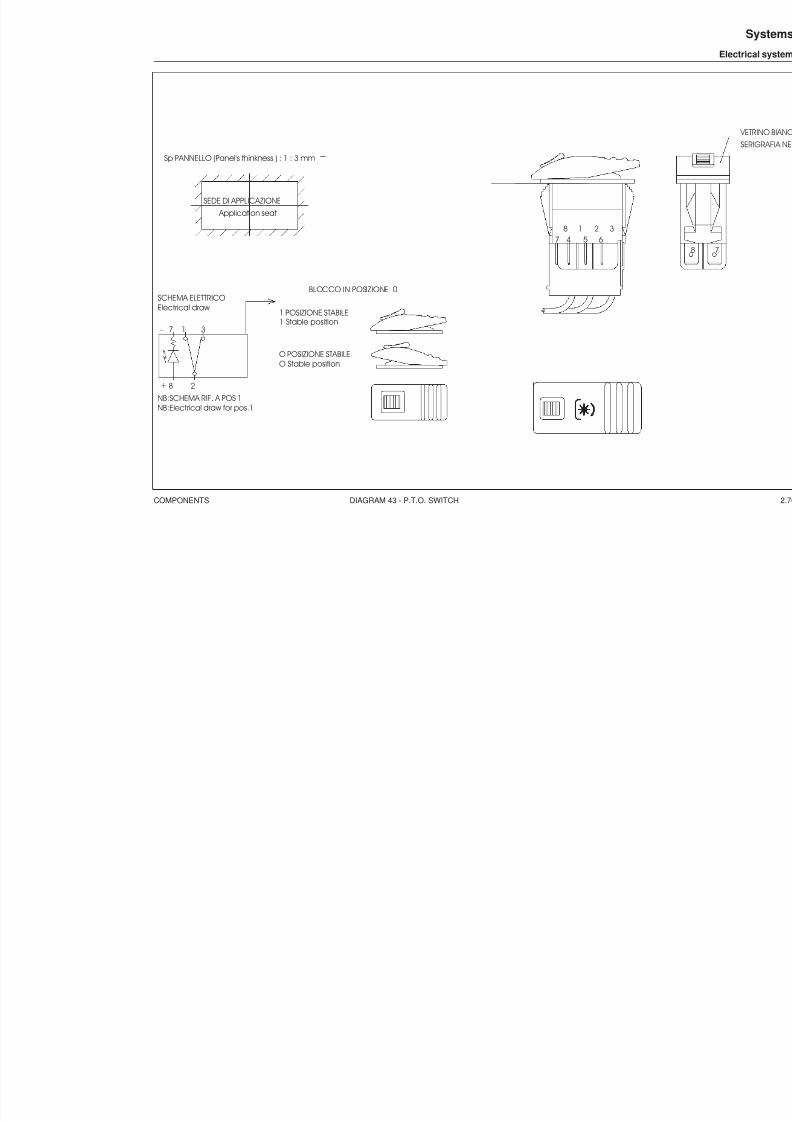
8/19/2019 Agrocompact f60 f70 f80 f90 Repair manual
http://slidepdf.com/reader/full/agrocompact-f60-f70-f80-f90-repair-manual 439/519
COMPONENTS DIAGRAM 43 - P.T.O. SWITCH
Sp PANNELLO (Panel's thinkness ) : 1 : 3 mm
SEDE DI APPLICAZIONE
Application seat
NB:Electrical draw for pos.1NB:SCHEMA RIF. A POS 1
Electrical draw SCHEMA ELETTRICO
O Stable positionO POSIZIONE STABILE
1 Stable position1 POSIZIONE STABILE
BLOCCO IN POSIZIONE 0
7 4 5 61 2 38
+ 8
7-
2
31

8/19/2019 Agrocompact f60 f70 f80 f90 Repair manual
http://slidepdf.com/reader/full/agrocompact-f60-f70-f80-f90-repair-manual 440/519
COMPONENTS DIAGRAM 44 - ROCKER SWITCH FOR STABILISER ADJUSTMENT
440
Systems
Electrical system
884
SEDE DI APPLICAZIONE
Application seat
31
2
Electrical drawSCHEMA ELETTRICO
2 Momentary position2 POSIZIONE INSTABILE
0 Stable position
0 POSIZIONE STABILE
1 POSIZIONE INSTABILE1 Momentary position2 0 1
POS.
NUMERI CORRISPONDENTI AL CONNETTORE 5 VIE SUPERSEAL
AMP
E V2 ( s x )
C OM.
1 2
E V 3 ( dx )
E V4 ( dx )
3 4
E V 5 ( s x )
5
3
1
2
AMP
5
4
U
G.T.R. (T.S.S.)
4 6
5 S X

8/19/2019 Agrocompact f60 f70 f80 f90 Repair manual
http://slidepdf.com/reader/full/agrocompact-f60-f70-f80-f90-repair-manual 441/519
COMPONENTS DIAGRAM 45 - SWITCH FOR RH LIFT ROD ADJUSTMENT
Sp PANNELLO (Panel's thinkness ) : 1 : 3 mm
SEDE DI APPLICAZIONE
Application seat
3
1
2
AMP
5
4 G.T.R. (T.S.S.)
31
2
Electrical draw SCHEMA ELETTRICO
2 Momentary position2 POSIZIONE INSTABILE
0 Stable position0 POSIZIONE STABILE
1 POSIZIONE INSTABILE1 Momentary position2 0 1
POS.
NUMERI CORRISPONDENTI AL CONNETTORE 5 VIE SUPERSEAL
A MP
E V 1
C OM.
1 2
E V 1
E V 7
3 4
E V 6
5
4 6
5

8/19/2019 Agrocompact f60 f70 f80 f90 Repair manual
http://slidepdf.com/reader/full/agrocompact-f60-f70-f80-f90-repair-manual 442/519
COMPONENTS DIAGRAM 46 - SWITCH FOR HYDRAULIC WAYS 3 - 3
442
Systems
Electrical system
884
Sp PANNELLO (Panel's thinkness ) : 1 : 3 mm
SEDE DI APPLICAZIONE
Application seat
36.8
2 1 . 1
8
3
1
2
AMP
5
4
COM
UP
DOWN
-LAMP
+LAMP
G.T.R. (T.S.S.)
3
2
Electrical draw SCHEMA ELETTRICO
0 Stable position0 POSIZIONE STABILE
1 POSIZIONE STABILE1 Stable position0 1
POS.
A MP
S P I A +
C OM.
1 2
E V 3 S P I A -
3 4
E V 5
5
6
5
7

8/19/2019 Agrocompact f60 f70 f80 f90 Repair manual
http://slidepdf.com/reader/full/agrocompact-f60-f70-f80-f90-repair-manual 443/519
COMPONENTS DIAGRAM 47 - SWITCH FOR HYDRAULIC WAYS 4 - 4
Sp PANNELLO (Panel's thinkness ) : 1 : 3 mm
SEDE DI APPLICAZIONE
Application seat
3 1
2
Electrical draw
SCHEMA ELETTRICO
2 Momentary position
2 POSIZIONE INSTABILE
0 Stable position
0 POSIZIONE STABILE
1 POSIZIONE STABILE
1 Momentary position
1 0 2
POS.
BLOCCO SOLO PER PASSARE DA POS.0 A POS 1
3
1
2 AMP
UP G.T.R. (T.S.S.)
31 2
A MP
S T A B .
C OM
I N S T .

8/19/2019 Agrocompact f60 f70 f80 f90 Repair manual
http://slidepdf.com/reader/full/agrocompact-f60-f70-f80-f90-repair-manual 444/519
COMPONENTS DIAGRAM 48 - LIFT CONTROL SWITCH
444
Systems
Electrical system
884
SEDE DI APPLICAZIONE Application seat
36.8
2 1
. 1
7 3 1
8 2
Electrical drawSCHEMA ELETTRICO
2 Momentary position2 POSIZIONE INSTABILE
0 Stable position0 POSIZIONE STABILE
1 POSIZIONE INSTABILE1 Momentary position2 0 1
POS. 3
1
2
AMP
5
4
COM
UP
DOWN
-LAMP
+LAMP
A MP
+ L A MP
-L A MP
1 2
D OWN
UP
3 4
C OM
5
2 3
. 9
49.1

8/19/2019 Agrocompact f60 f70 f80 f90 Repair manual
http://slidepdf.com/reader/full/agrocompact-f60-f70-f80-f90-repair-manual 445/519
APPENDIX
ENGINE ELECTRONIC CONTROL UNIT
POWER LIFT TESTER (version 1.24A)

8/19/2019 Agrocompact f60 f70 f80 f90 Repair manual
http://slidepdf.com/reader/full/agrocompact-f60-f70-f80-f90-repair-manual 446/519
ENGINE ELECTRONIC CONTROL UNIT
I
Appendix
Engine electronic control unit
8/19/2019 Agrocompact f60 f70 f80 f90 Repair manual
http://slidepdf.com/reader/full/agrocompact-f60-f70-f80-f90-repair-manual 447/519
Engine electronic control unit
TESTER manual
CONTENTS
Presentation screen...............................................................................................................................III
Functional diagram................................................................................................................................IV
1 Main Menu .......................................................................... ................................................................V
1 Engine menu ....................................................................... ...............................................................VI1 Configuration ................................................................................ .................................................VII
1 Engine type .............................................................................. .................................................VIII2 Hand throttle calibration ................................................................................. ..............................X3 Accelerator pedal calibration ......................................................................... ..............................XI4 Idle speed calibration ......................................................................... ........................................XII
2 Calibration....................................................................................................................................XIV3 Monitor ..........................................................................................................................................XV
2 HML menu .................................................................................. .....................................................XVI1 Configuration...............................................................................................................................XVII2 Tests .................................................................................... ......................................................XVIII3 Monitor ..........................................................................................................................................XX
3 Preheating menu .............................................................................................................................XXI1 Configuration...............................................................................................................................XXII2 Tests..........................................................................................................................................XXIV3 Monitor.......................................................................................................................................XXVI
4 Alarms menu ....................................................................... .........................................................XXVII1 Initialisation ........................................................................... ...................................................XXVIII2 Monitor........................................................................................................................................XXX
5 Belts control system menu............................................................................ ................................XXXI1 Configuration ................................................................................ ............................................XXXII2 Tests........................................................................................................................................XXXIII3 Monitor ....................................................................................................................................XXXIV
6 Wheels menu (maximum speed limiting system).........................................................................XXXV1 Configuration...........................................................................................................................XXXVI2 Monitor ..................................................................................................................................XXXVIII
7 P.T.O. menu................................................................................................................................XXXIX1 Calibration .....................................................................................................................................XL2 Tests.............................................................................................................................................XLI3 Monitor.........................................................................................................................................XLII
Engine Type/Wheels Constant tables .................................................................................. .............XLIII
Alarms list .......................................................................... ...............................................................XLIV
II
Appendix
Engine electronic control unit
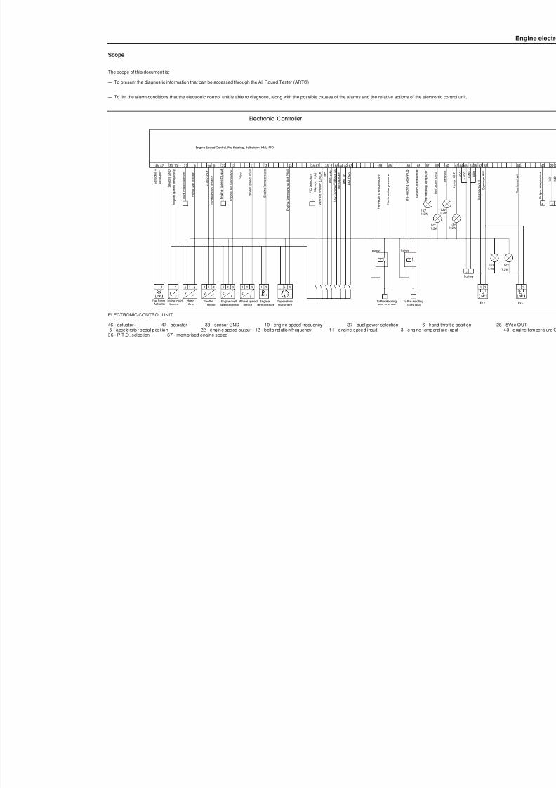
8/19/2019 Agrocompact f60 f70 f80 f90 Repair manual
http://slidepdf.com/reader/full/agrocompact-f60-f70-f80-f90-repair-manual 448/519
V
2
Throttle
Engine Speed Control, Pre-Heating, Belt alarm, HML, PTO
E n g i n e
S p e e d O u t p u t
H a n d
G a s
P o s i t i o n
E n g i n e S p e e d F r e q u e n c y
S e n s o r s
G N D
A c t u a t o r
-
Engine Speed Actuator
Fuel PumpsF
Sensor
2
F
121M
A c t u a t o r
+
+ 5 V c c O U T
E n g i n e B e l t F r e q u e n c y
P r e - H
e a t i n g L a m p O u t
W h e e l s p e e d i n p u t
E n g i n e T e m p e r a t u r e
P r e - H
e a t i n g G l o w - P l u g
T h r o t t l e P e d a l P o s i t i o n
Engine beltspeed sensorPedal
1 4 21
FF
EngineTemperature
3
Batte
1 2
t
+ V C C
+ V C C
H a n d b r a k e
B e l t a l a r m l a m p
Electronic Controller
H M L
U p
H M L
D w n
12V 1.2W
12V 1.2W
Wheel speedsensor
2
F
1
F
3
Glow plug
46 47 33 10 6 28 5 22 12 11 3 64 62 63 56 57 59 44 45 2560
1.2W
L a m p M
12V
1.2W 12V
L a m p H O L D
61
HandGas
V
2 1 4
To Pre-Heating
P r e - H
e a t i n g e l e c t r o v a l v e
58
Relay
electrovalve
+ -
E l e c t r o v a l v e p r e s e n c e
65
Relay
G l o w P l u g p r e s e n c e
68
M
e m o r y
H o l d
67
V p p
35
D u a l P o w e r
S l e c t i o n
37
TeperatureInstrument
+- S
43
E n g i n e T e m p e r a t u r e O u t P W M
36
P T O S e l e c t i o n
R e a r
L i f t P o s i t i o n ( O n / O f f )
8
P T O
9
P T O a u t o
66
L o w E n g i n e O i l P r e s s u r e
To Pre-Heating
Scope
The scope of this document is:
— To present the diagnostic information that can be accessed through the All Round Tester (ART®)
— To list the alarm conditions that the electronic control unit is able to diagnose, along with the possible causes of the alarms and the relative actions of the electronic control unit.
ELECTRONIC CONTROL UNIT
46 - actuator+ 47 - actuator - 33 - sensor GND 10 - engine speed frequency 37 - dual power selection 6 - hand throttle position 5 - accelerator pedal posit ion 22 - engine speed output 12 - belts rotat ion frequency 11 - engine speed input 3 - engine temperature input
36 - P.T.O. selection 67 - memorised engine speed
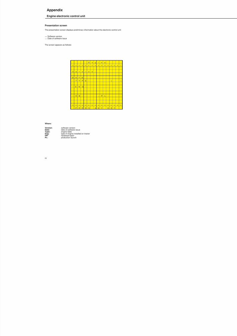
8/19/2019 Agrocompact f60 f70 f80 f90 Repair manual
http://slidepdf.com/reader/full/agrocompact-f60-f70-f80-f90-repair-manual 449/519
Presentation screen
The presentation screen displays preliminary information about the electronic control unit:
— Software version— Date of software issue
The screen appears as follows:
E n g i n e
= = = = = = = = = = = = = = = =
V e r s i o n :
D A T E
- T Y P E : ( )
- E N G :
- H B : - P L :
= = = = = = = = = = = = = = = =
P R E S S A N Y K E Y
Where:
Version : software versionDate: date of software issueType: engine tableEng: type of engine installed on tractorHB: hardware batchPL: production launch
IV
Appendix
Engine electronic control unit
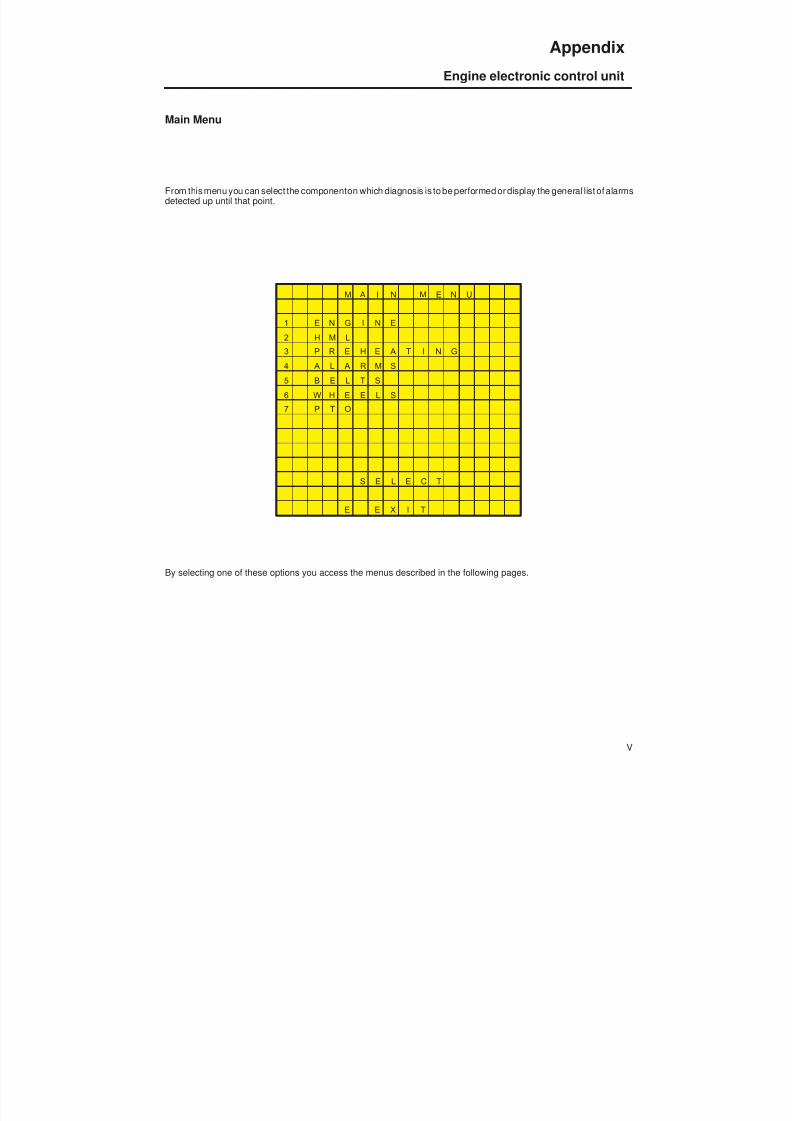
8/19/2019 Agrocompact f60 f70 f80 f90 Repair manual
http://slidepdf.com/reader/full/agrocompact-f60-f70-f80-f90-repair-manual 450/519
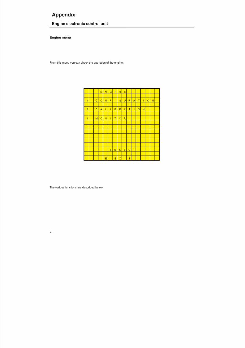
8/19/2019 Agrocompact f60 f70 f80 f90 Repair manual
http://slidepdf.com/reader/full/agrocompact-f60-f70-f80-f90-repair-manual 451/519
Engine menu
From this menu you can check the operation of the engine.
E N G I N E
1 C O N F I G U R A T I O N
2 C A L I B R A T I O N
3 M O N I T O R
S E L E C T
E E X I T
The various functions are described below.
VI
Appendix
Engine electronic control unit

8/19/2019 Agrocompact f60 f70 f80 f90 Repair manual
http://slidepdf.com/reader/full/agrocompact-f60-f70-f80-f90-repair-manual 452/519
Engine menu
Configuration menu
From this menu you can configure and calibrate the following parameters:
1 engine type2 hand throttle calibration3 accelerator pedal calibration4 idle speed calibration
The following menu is displayed on the ART.
C O N F I G U R A T I O N
1 E N G I N E T Y P E
2 H A N D T H R O T . C A
3 A C C . P E D . C A L .
4 I D L E S P E E D C A L
S E L E C T
E E X I T
The various functions are described below.
VII
Appendix
Engine electronic control unit
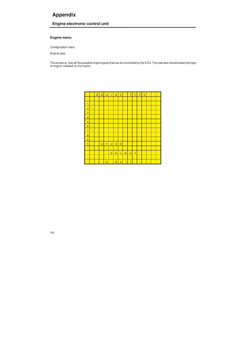
8/19/2019 Agrocompact f60 f70 f80 f90 Repair manual
http://slidepdf.com/reader/full/agrocompact-f60-f70-f80-f90-repair-manual 453/519
Engine menu
Configuration menu
Engine type
This screen p. lists all the possible engine types that can be controlled by the ECU. The operator should select the typeof engine installed on the tractor.
E N G I N E T Y P E
1 -
2 -
3 -
4 -
5 -
6 -7 -
8 -
9 -
0 - O T H E R
S E L E C T
E E X I T
VIII
Appendix
Engine electronic control unit
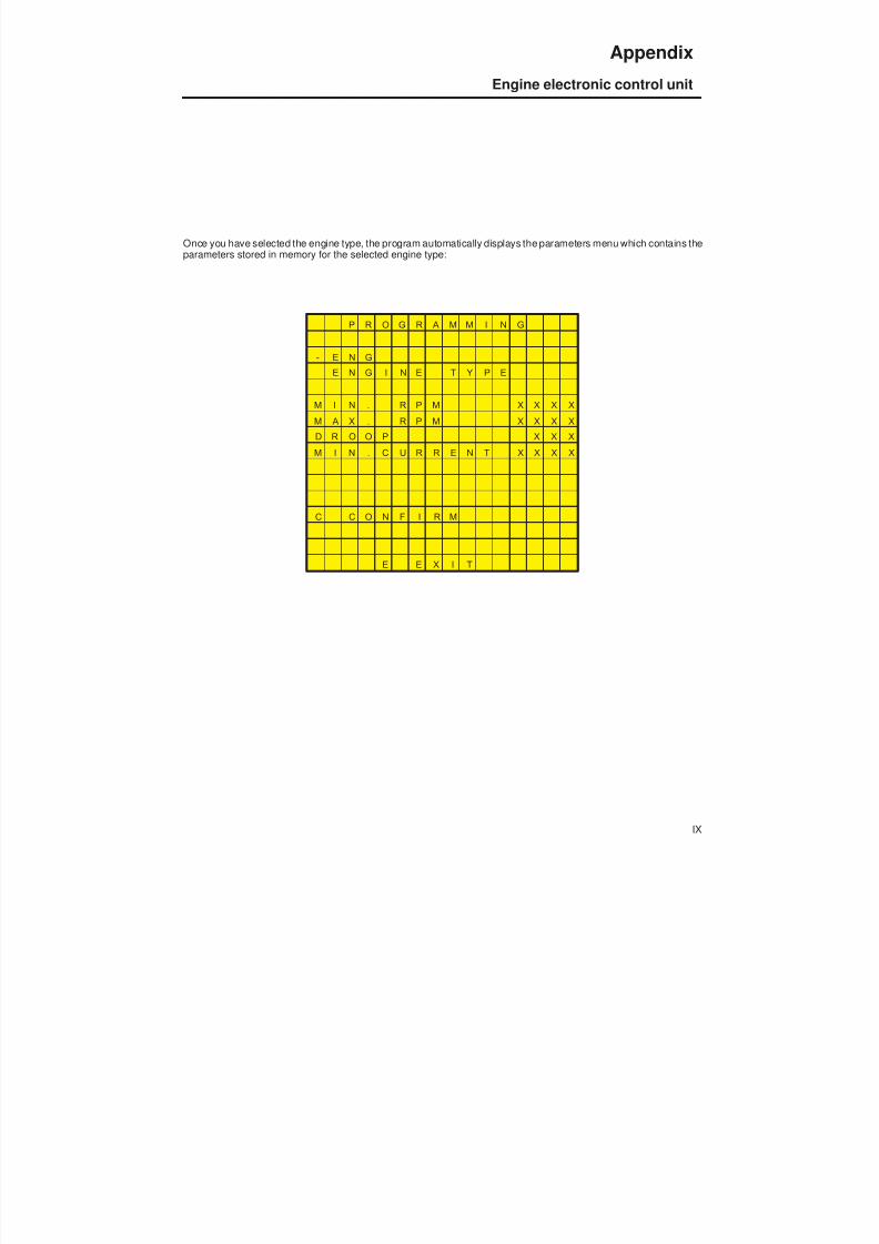
8/19/2019 Agrocompact f60 f70 f80 f90 Repair manual
http://slidepdf.com/reader/full/agrocompact-f60-f70-f80-f90-repair-manual 454/519
Once you have selected the engine type, the program automatically displays the parameters menu which contains theparameters stored in memory for the selected engine type:
P R O G R A M M I N G
- E N G
E N G I N E T Y P E
M I N . R P M X X X X
M A X . R P M X X X X
D R O O P X X X
M I N . C U R R E N T X X X X
C C O N F I R M
E E X I T
IX
Appendix
Engine electronic control unit
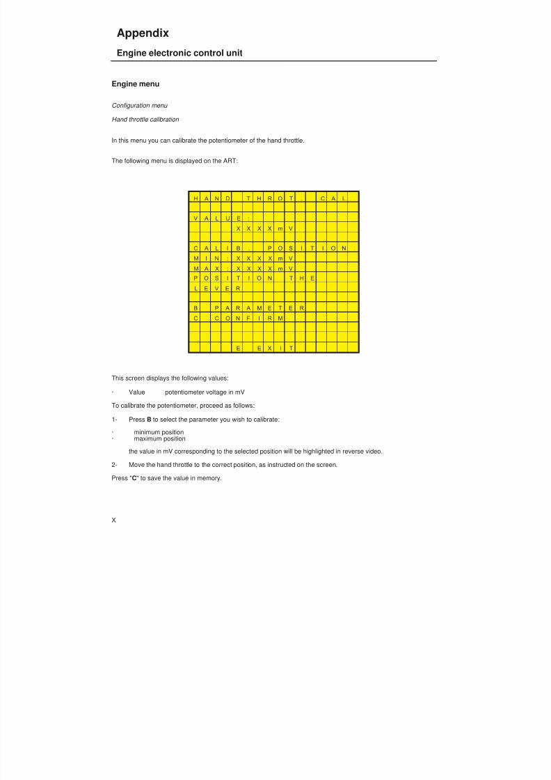
8/19/2019 Agrocompact f60 f70 f80 f90 Repair manual
http://slidepdf.com/reader/full/agrocompact-f60-f70-f80-f90-repair-manual 455/519
Engine menu
Configuration menu
Hand throttle calibration
In this menu you can calibrate the potentiometer of the hand throttle.
The following menu is displayed on the ART:
H A N D T H R O T . C A L .
V A L U E :
X X X X m V
C A L I B . P O S I T I O N :
M I N : X X X X m V
M A X : X X X X m V
P O S I T I O N T H E
L E V E R
B P A R A M E T E R
C C O N F I R M
E E X I T
This screen displays the following values:
· Value potentiometer voltage in mV
To calibrate the potentiometer, proceed as follows:
1- Press B to select the parameter you wish to calibrate:
· minimum position· maximum position
the value in mV corresponding to the selected position will be highlighted in reverse video.
2- Move the hand throttle to the correct position, as instructed on the screen.
Press " C" to save the value in memory.
X
Appendix
Engine electronic control unit
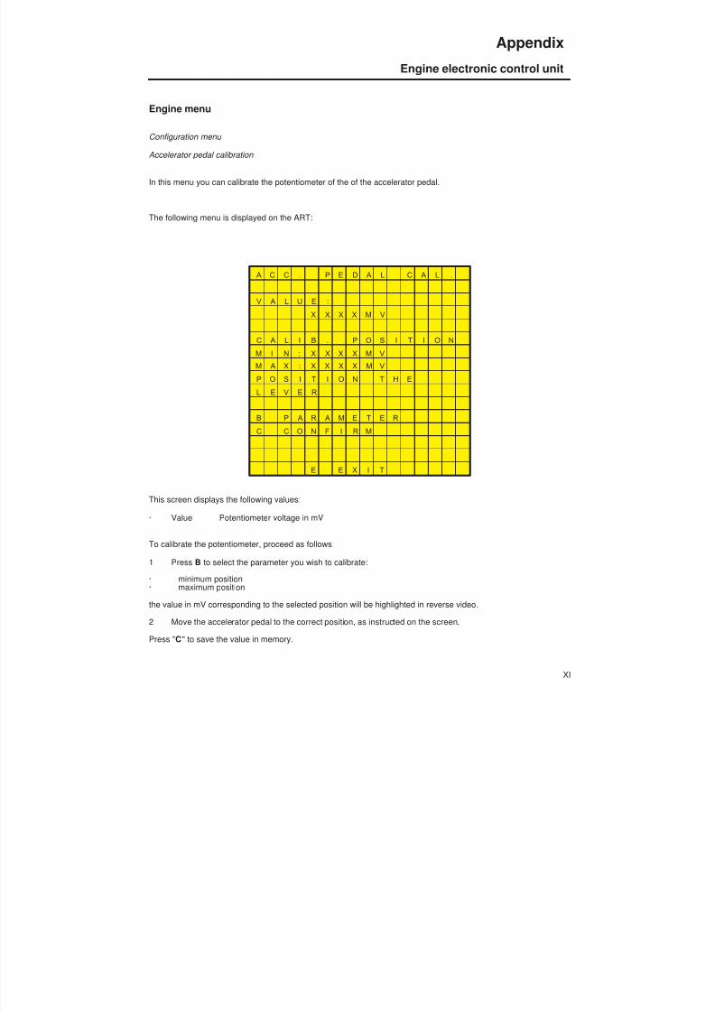
8/19/2019 Agrocompact f60 f70 f80 f90 Repair manual
http://slidepdf.com/reader/full/agrocompact-f60-f70-f80-f90-repair-manual 456/519
Engine menu
Configuration menu
Accelerator pedal calibration
In this menu you can calibrate the potentiometer of the of the accelerator pedal.
The following menu is displayed on the ART:
A C C . P E D A L C A L .
V A L U E :
X X X X M V
C A L I B . P O S I T I O N
M I N : X X X X M V
M A X : X X X X M VP O S I T I O N T H E
L E V E R
B P A R A M E T E R
C C O N F I R M
E E X I T
This screen displays the following values:
· Value Potentiometer voltage in mV
To calibrate the potentiometer, proceed as follows:
1 Press B to select the parameter you wish to calibrate:
· minimum position· maximum position
the value in mV corresponding to the selected position will be highlighted in reverse video.
2 Move the accelerator pedal to the correct position, as instructed on the screen.
Press " C " to save the value in memory.
XI
Appendix
Engine electronic control unit
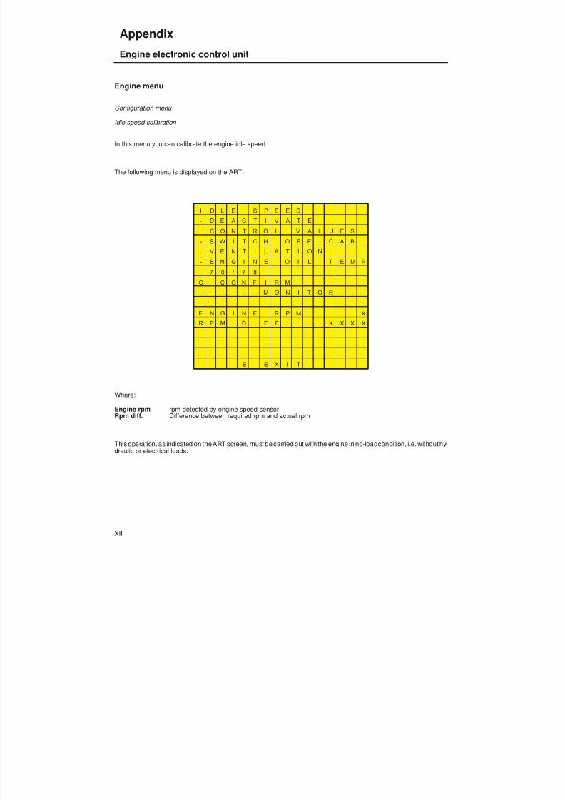
8/19/2019 Agrocompact f60 f70 f80 f90 Repair manual
http://slidepdf.com/reader/full/agrocompact-f60-f70-f80-f90-repair-manual 457/519
Engine menu
Configuration menu
Idle speed calibration
In this menu you can calibrate the engine idle speed.
The following menu is displayed on the ART:
I D L E S P E E D
- D E A C T I V A T E
C O N T R O L V A L U E S
- S W I T C H O F F C A B
V E N T I L A T I O N
- E N G I N E O I L T E M P
7 0 / 7 8
C C O N F I R M
- - - - - - M O N I T O R - - -
E N G I N E R P M X
R P M D I F F . X X X X
E E X I T
Where:
Engine rpm rpm detected by engine speed sensorRpm diff. Difference between required rpm and actual rpm
This operation, as indicated on theART screen, must be carried out with the engine in no-loadcondition, i.e. withouthy -draulic or electrical loads.
XII
Appendix
Engine electronic control unit

8/19/2019 Agrocompact f60 f70 f80 f90 Repair manual
http://slidepdf.com/reader/full/agrocompact-f60-f70-f80-f90-repair-manual 458/519
Calibration procedure:
1 Wait until the rpm difference value stabilises.2 Press "C" on the ART to save the value in EEprom.3 There are three possible outcomes:
Parameter correctly programmed: the ART displays the following message:
P A R A M E T E R
P R O G R A M M E D
If the rpm difference exceeds 40, the following message is displayed:
R P M D I F F . 4 0
If the electronic control unit has problems writing to the EEprom, the calibration operation is not performed and thefollowing message is displayed:
E e P R O M F A U L T
XIII
Appendix
Engine electronic control unit
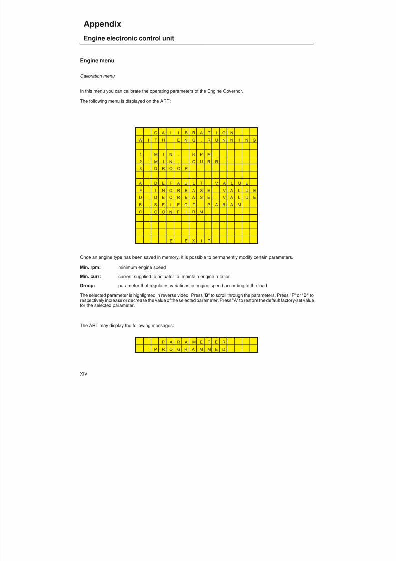
8/19/2019 Agrocompact f60 f70 f80 f90 Repair manual
http://slidepdf.com/reader/full/agrocompact-f60-f70-f80-f90-repair-manual 459/519
Engine menu
Calibration menu
In this menu you can calibrate the operating parameters of the Engine Governor.
The following menu is displayed on the ART:
C A L I B R A T I O N
W I T H E N G . R U N N I N G
1 M I N . R P M
2 M I N . C U R R .
3 D R O O P
A D E F A U L T V A L U E
F I N C R E A S E V A L U E
D D E C R E A S E V A L U E
B S E L E C T P A R A M .C C O N F I R M
E E X I T
Once an engine type has been saved in memory, it is possible to permanently modify certain parameters.
Min. rpm: minimum engine speed
Min. curr: current supplied to actuator to maintain engine rotation
Droop: parameter that regulates variations in engine speed according to the load
The selected parameter is highlighted in reverse video. Press " B" to scroll through the parameters. Press " F" or "D" torespectively increase or decrease the value of the selected parameter. Press "A" to restore the default factory-set valuefor the selected parameter.
The ART may display the following messages:
P A R A M E T E R
P R O G R A M M E D
XIV
Appendix
Engine electronic control unit
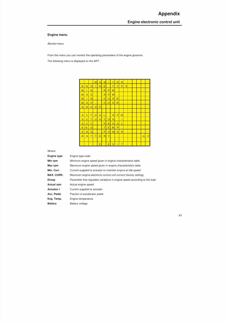
8/19/2019 Agrocompact f60 f70 f80 f90 Repair manual
http://slidepdf.com/reader/full/agrocompact-f60-f70-f80-f90-repair-manual 460/519
Engine menu
Monitor menu
From this menu you can monitor the operating parameters of the engine governor.
The following menu is displayed on the ART:
M O N I T O R
E N G I N E T Y P E
M I N . R P M
M A X . R P M
M I N . C U R R .
M A X . C U R R .
D R O O P
A C T U A L R P M
A C T U A T O R I
A C C . P E D A L
E N G . T E M P .
E N G . P O W E R
B A T T E R Y m V
E E X I T
Where:
Engine type Engine type codeMin rpm Minimum engine speed given in engine characteristics table
Max rpm Maximum engine speed given in engine characteristics table
Min. Curr. . Current supplied to actuator to maintain engine at idle speed
MAX. CURR. . Maximum engine electronic control unit current (factory setting)
Droop Parameter that regulates variations in engine speed according to the load
Actual rpm Actual engine speed
Actuator I Current supplied to actuator
Acc. Pedal . Position of accelerator pedal
Eng. Temp. Engine temperature
Battery Battery voltage
XV
Appendix
Engine electronic control unit
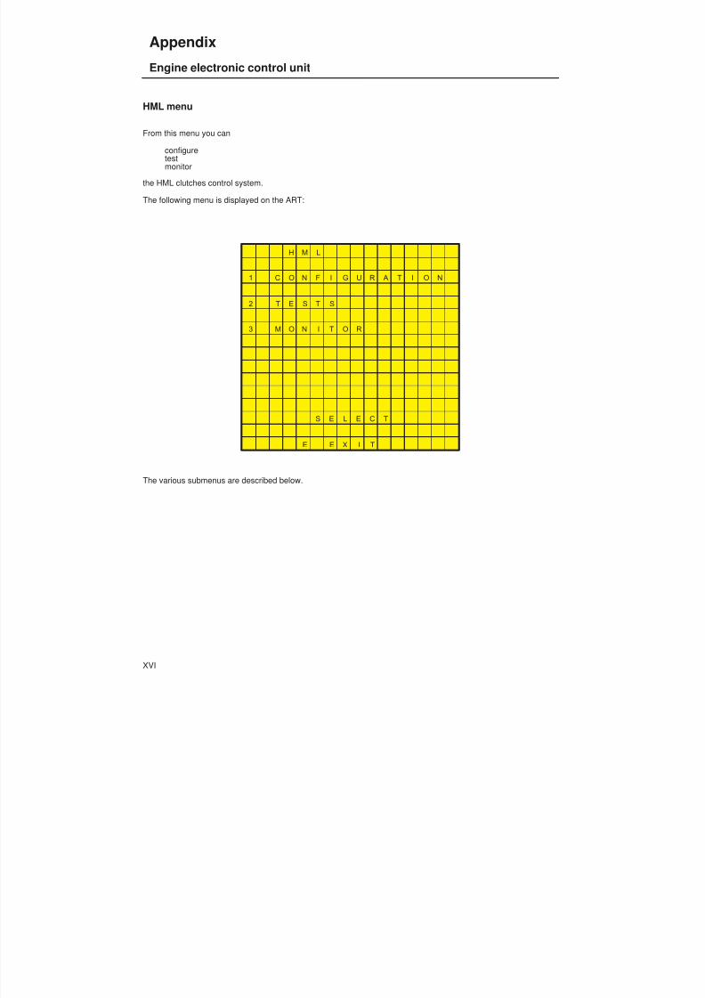
8/19/2019 Agrocompact f60 f70 f80 f90 Repair manual
http://slidepdf.com/reader/full/agrocompact-f60-f70-f80-f90-repair-manual 461/519
HML menu
From this menu you can
configuretestmonitor
the HML clutches control system.
The following menu is displayed on the ART:
H M L
1 C O N F I G U R A T I O N
2 T E S T S
3 M O N I T O R
S E L E C T
E E X I T
The various submenus are described below.
XVI
Appendix
Engine electronic control unit
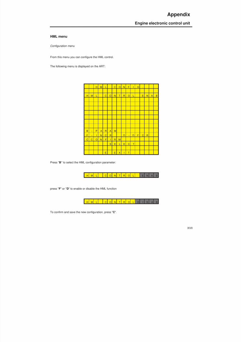
8/19/2019 Agrocompact f60 f70 f80 f90 Repair manual
http://slidepdf.com/reader/full/agrocompact-f60-f70-f80-f90-repair-manual 462/519
HML menu
Configuration menu
From this menu you can configure the HML control.
The following menu is displayed on the ART:
H M L C O N F I G .
H M L C O N T R O L E N A B
B - P A R A M .
F - I N C R . D - D E C R .
C C O N F I R M
S E L E C T
E E X I T
Press " B " to select the HML configuration parameter:
H M L C O N T R O L E N A B
press " F" or "D" to enable or disable the HML function
H M L C O N T R O L D I S A B
To confirm and save the new configuration, press " C".
XVII
Appendix
Engine electronic control unit

8/19/2019 Agrocompact f60 f70 f80 f90 Repair manual
http://slidepdf.com/reader/full/agrocompact-f60-f70-f80-f90-repair-manual 463/519
HML menu
Tests menu
From this menu you can test the operation of the HML system.
The following menu is displayed on the ART:
T E S T S
U P P B O F F
D O W N P B O F F
1 H S V m A
2 L SV m A
3 M L A M P O F F
E E X I T
The following components of the HML system may be tested directly:
UP pushbutton Press this pushbutton to test the electrical continuity and mechanicalintegrity of the pushbutton.
With pushbutton on joystick pressed:
U P P B O N
With pushbutton released
U P P B O F F
XVIII
Appendix
Engine electronic control unit
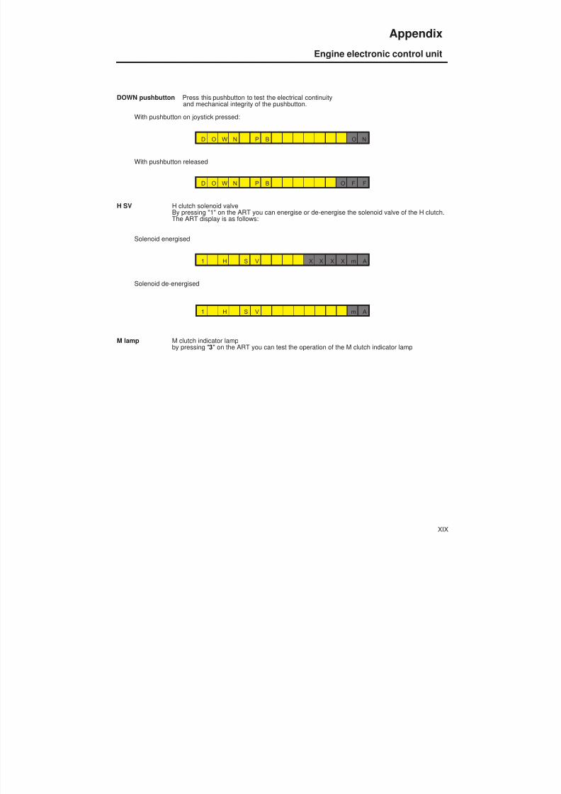
8/19/2019 Agrocompact f60 f70 f80 f90 Repair manual
http://slidepdf.com/reader/full/agrocompact-f60-f70-f80-f90-repair-manual 464/519
DOWN pushbutton Press this pushbutton to test the electrical continuityand mechanical integrity of the pushbutton.
With pushbutton on joystick pressed:
D O W N P B O N
With pushbutton released
D O W N P B O F F
H SV H clutch solenoid valveBy pressing "1" on the ART you can energise or de-energise the solenoid valve of the H clutch.The ART display is as follows:
Solenoid energised
1 H S V X X X X m A
Solenoid de-energised
1 H S V m A
M lamp M clutch indicator lampby pressing " 3" on the ART you can test the operation of the M clutch indicator lamp
XIX
Appendix
Engine electronic control unit
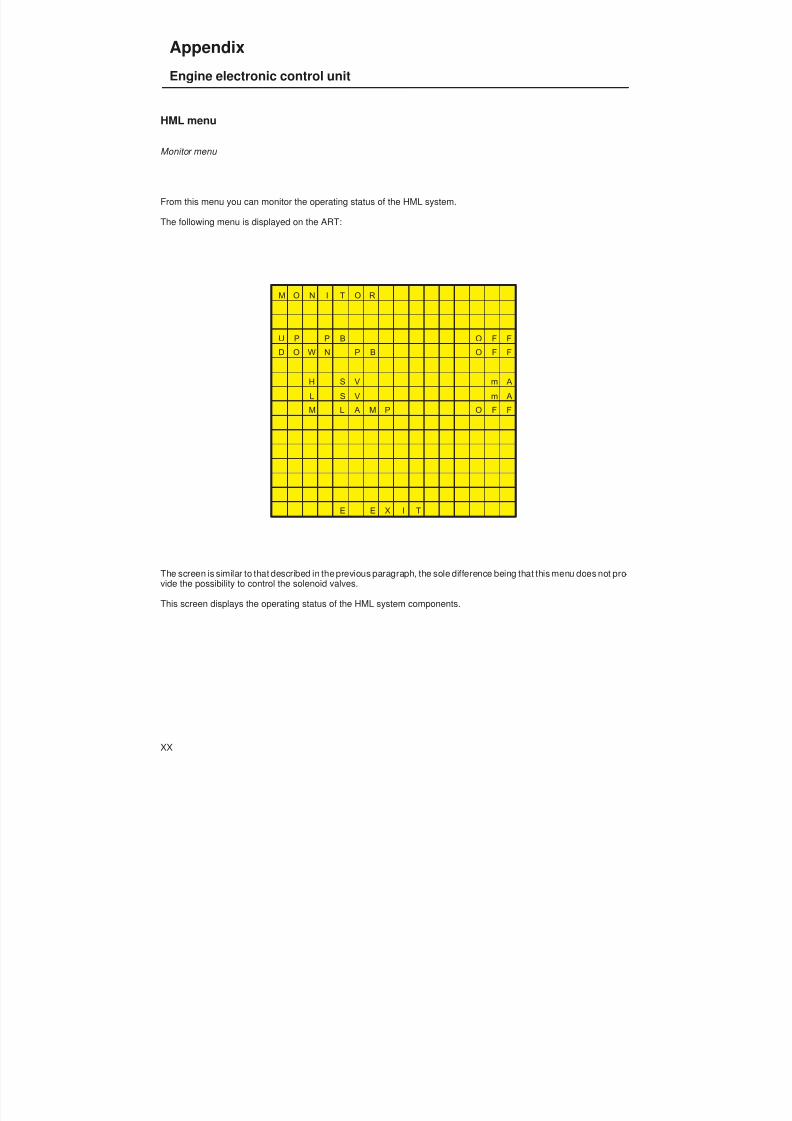
8/19/2019 Agrocompact f60 f70 f80 f90 Repair manual
http://slidepdf.com/reader/full/agrocompact-f60-f70-f80-f90-repair-manual 465/519
HML menu
Monitor menu
From this menu you can monitor the operating status of the HML system.
The following menu is displayed on the ART:
M O N I T O R
U P P B O F F
D O W N P B O F F
H S V m A
L S V m A
M L A M P O F F
E E X I T
The screen is similar to that described in the previous paragraph, the sole difference being that this menu does not pro -vide the possibility to control the solenoid valves.
This screen displays the operating status of the HML system components.
XX
Appendix
Engine electronic control unit

8/19/2019 Agrocompact f60 f70 f80 f90 Repair manual
http://slidepdf.com/reader/full/agrocompact-f60-f70-f80-f90-repair-manual 466/519
Preheating menu
From this menu you can· configure· test· monitor
the preheating system.
The following menu is displayed on the ART:
P R E H E A T I N G
1 C O N F I G U R A T I O N
2 T E S T S
3 M O N I T O R
S E L E C T
E E X I T
The various submenus are described below.
XXI
Appendix
Engine electronic control unit
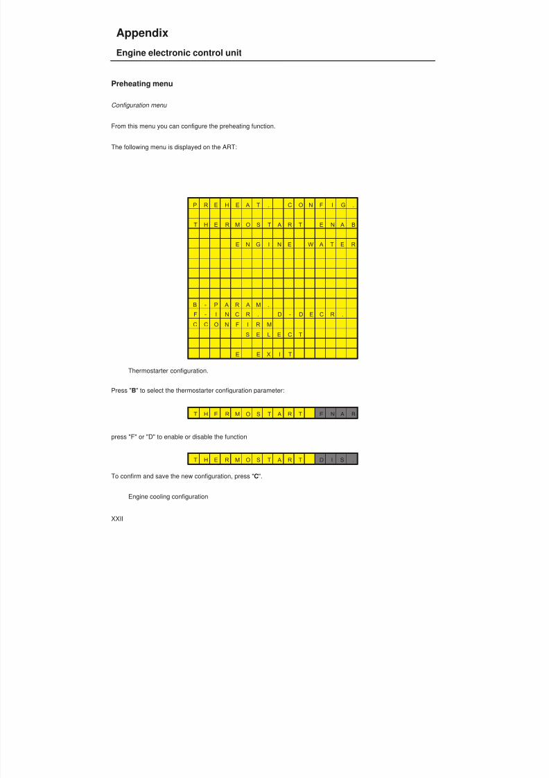
8/19/2019 Agrocompact f60 f70 f80 f90 Repair manual
http://slidepdf.com/reader/full/agrocompact-f60-f70-f80-f90-repair-manual 467/519
Preheating menu
Configuration menu
From this menu you can configure the preheating function.
The following menu is displayed on the ART:
P R E H E A T . C O N F I G .
T H E R M O S T A R T E N A B
E N G I N E W A T E R
B - P A R A M .
F - I N C R . D - D E C R .
C C O N F I R M
S E L E C T
E E X I T
Thermostarter configuration.
Press " B" to select the thermostarter configuration parameter:
T H E R M O S T A R T E N A B
press "F" or "D" to enable or disable the function
T H E R M O S T A R T D I S .
To confirm and save the new configuration, press " C".
Engine cooling configuration
XXII
Appendix
Engine electronic control unit

8/19/2019 Agrocompact f60 f70 f80 f90 Repair manual
http://slidepdf.com/reader/full/agrocompact-f60-f70-f80-f90-repair-manual 468/519
The type of engine cooling (water or air) determines the type of sensor used to measure the engine temperature.
Press " B " to select the engine cooling configuration parameter. The ART screen appears as follows:
E N G I N E W A T E R
press " F" or "D" to change the cooling type
E N G I N E A I R
XXIII
Appendix
Engine electronic control unit
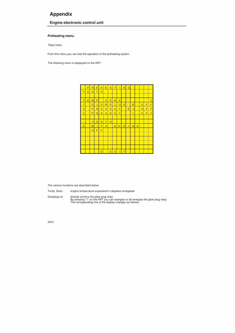
8/19/2019 Agrocompact f60 f70 f80 f90 Repair manual
http://slidepdf.com/reader/full/agrocompact-f60-f70-f80-f90-repair-manual 469/519
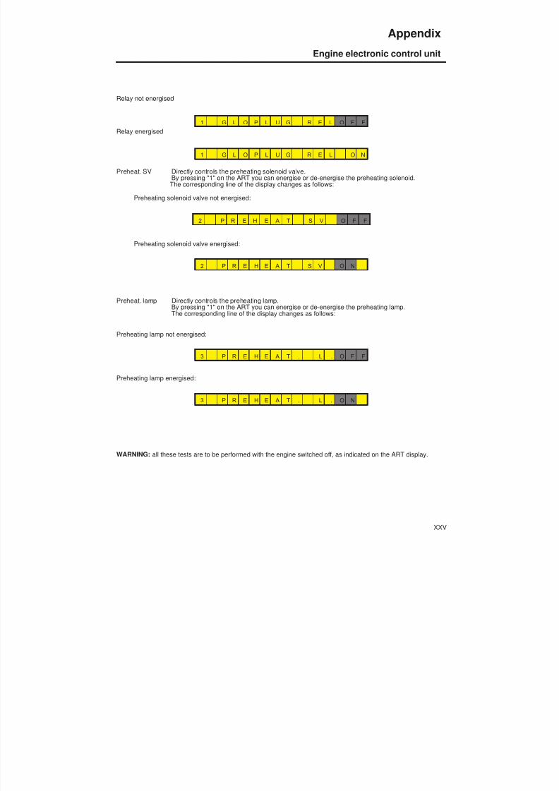
8/19/2019 Agrocompact f60 f70 f80 f90 Repair manual
http://slidepdf.com/reader/full/agrocompact-f60-f70-f80-f90-repair-manual 470/519
Relay not energised
1 G L O P L U G R E L O F F
Relay energised
1 G L O P L U G R E L O N
Preheat. SV Directly controls the preheating solenoid valve.By pressing "1" on the ART you can energise or de-energise the preheating solenoid.The corresponding line of the display changes as follows:
Preheating solenoid valve not energised:
2 P R E H E A T S V O F F
Preheating solenoid valve energised:
2 P R E H E A T S V O N
Preheat. lamp Directly controls the preheating lamp.By pressing "1" on the ART you can energise or de-energise the preheating lamp.The corresponding line of the display changes as follows:
Preheating lamp not energised:
3 P R E H E A T . L . O F F
Preheating lamp energised:
3 P R E H E A T . L . O N
WARNING: all these tests are to be performed with the engine switched off, as indicated on the ART display.
XXV
Appendix
Engine electronic control unit

8/19/2019 Agrocompact f60 f70 f80 f90 Repair manual
http://slidepdf.com/reader/full/agrocompact-f60-f70-f80-f90-repair-manual 471/519
Preheating menu
Monitor menu
In this menu you can monitor the operation of the preheating system.
The following menu is displayed on the ART:
P R E H E A T I N G
M O N I T O R
T E M P . S E N S . C
G L O P L U G R E . O F F
P R E H E A T . S V . O F F
P R E H E A T . L . O F F
E E X I T
The screen is similar to that described in the previous paragraph, the sole difference being that this menu does not pro -vide the possibility to control the various functions.
This screen displays the operating status of the preheating system components.
XXVI
Appendix
Engine electronic control unit

8/19/2019 Agrocompact f60 f70 f80 f90 Repair manual
http://slidepdf.com/reader/full/agrocompact-f60-f70-f80-f90-repair-manual 472/519
Alarms menu
From this menu you can:initialise the alarmsdisplay the alarms log.
The following menu is displayed on the ART:
A L A R M S
1 I N I T I A L I S .
2 M O N I T O R
S E L E C T
E E X I T
The various functions are described below.
XXVII
Appendix
Engine electronic control unit

8/19/2019 Agrocompact f60 f70 f80 f90 Repair manual
http://slidepdf.com/reader/full/agrocompact-f60-f70-f80-f90-repair-manual 473/519
Alarms menu
Initialisation menu
This operation is only required as part of the putting into the service procedure, generally after installing a later versionof the software.
If the new and previous software versions are compatible, the ART will display the following screen:
A L A R M S
E E P R O M O K
E E X I T
Otherwise:
A L A R M S
E E P R O M E R R O R
T O E L I M I N A T EP R E S S C
E E X I T
On pressing "C " on the ART, the electronic control unit will reset this alarm.
XXVIII
Appendix
Engine electronic control unit
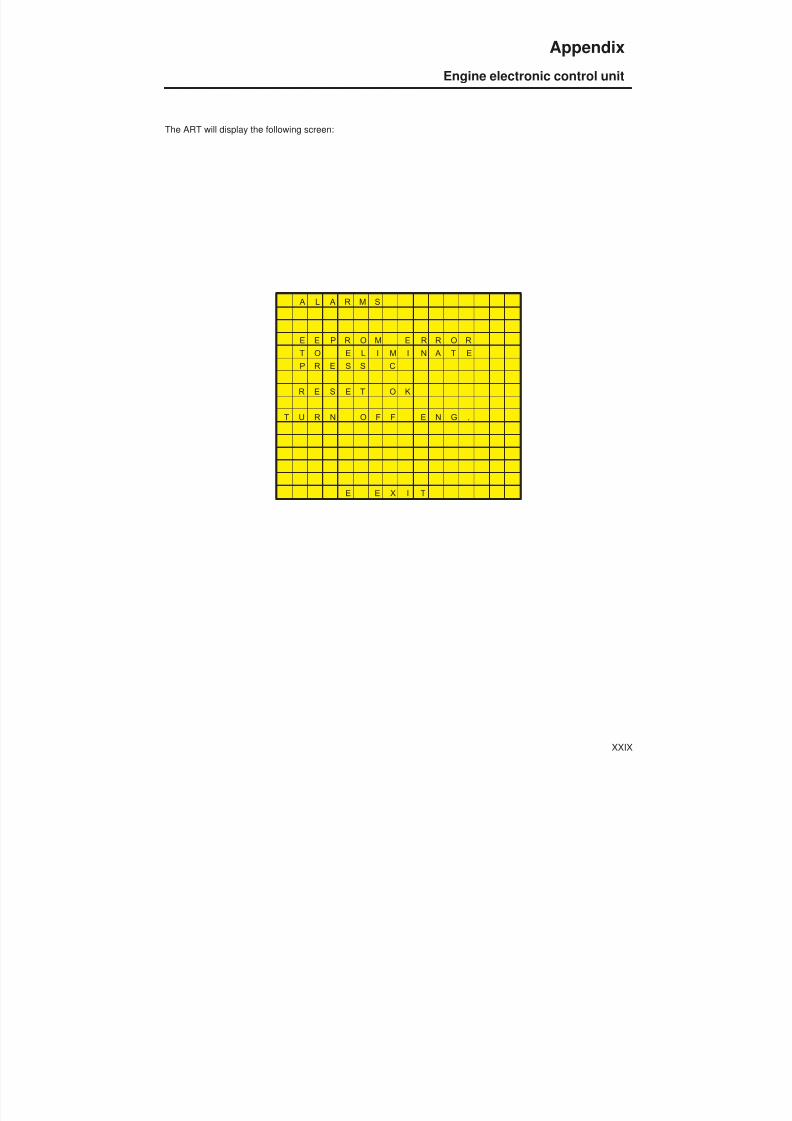
8/19/2019 Agrocompact f60 f70 f80 f90 Repair manual
http://slidepdf.com/reader/full/agrocompact-f60-f70-f80-f90-repair-manual 474/519
The ART will display the following screen:
A L A R M S
E E P R O M E R R O R
T O E L I M I N A T E
P R E S S C
R E S E T O K
T U R N O F F E N G .
E E X I T
XXIX
Appendix
Engine electronic control unit

8/19/2019 Agrocompact f60 f70 f80 f90 Repair manual
http://slidepdf.com/reader/full/agrocompact-f60-f70-f80-f90-repair-manual 475/519
Alarms menu
Monitor menu
This screen displays the list of alarms detected by the system. The most recent alarm is first in the list.Pressing "A" cancels the list and resets the alarm log.
The screen displayed on the ART is as follows:
A L A R M S L O G
O . C . A . = O p e n C i r c
S . C . = S h o r t C i r c .
A - R E S E T A L . L O G
E E X I T
Heading 4 contains a list of all the alarms that can be detected by the electronic control unit.
XXX
Appendix
Engine electronic control unit

8/19/2019 Agrocompact f60 f70 f80 f90 Repair manual
http://slidepdf.com/reader/full/agrocompact-f60-f70-f80-f90-repair-manual 476/519
Belts menu
From this menu you can· configure· test· monitor
the drive belts control system.
The following menu is displayed on the ART:
B E L T S
1 C O N F I G U R A T I O N
2 T E S T S
3 M O N I T O R
S E L E C T
E E X I T
The various submenus are described below.
XXXI
Appendix
Engine electronic control unit
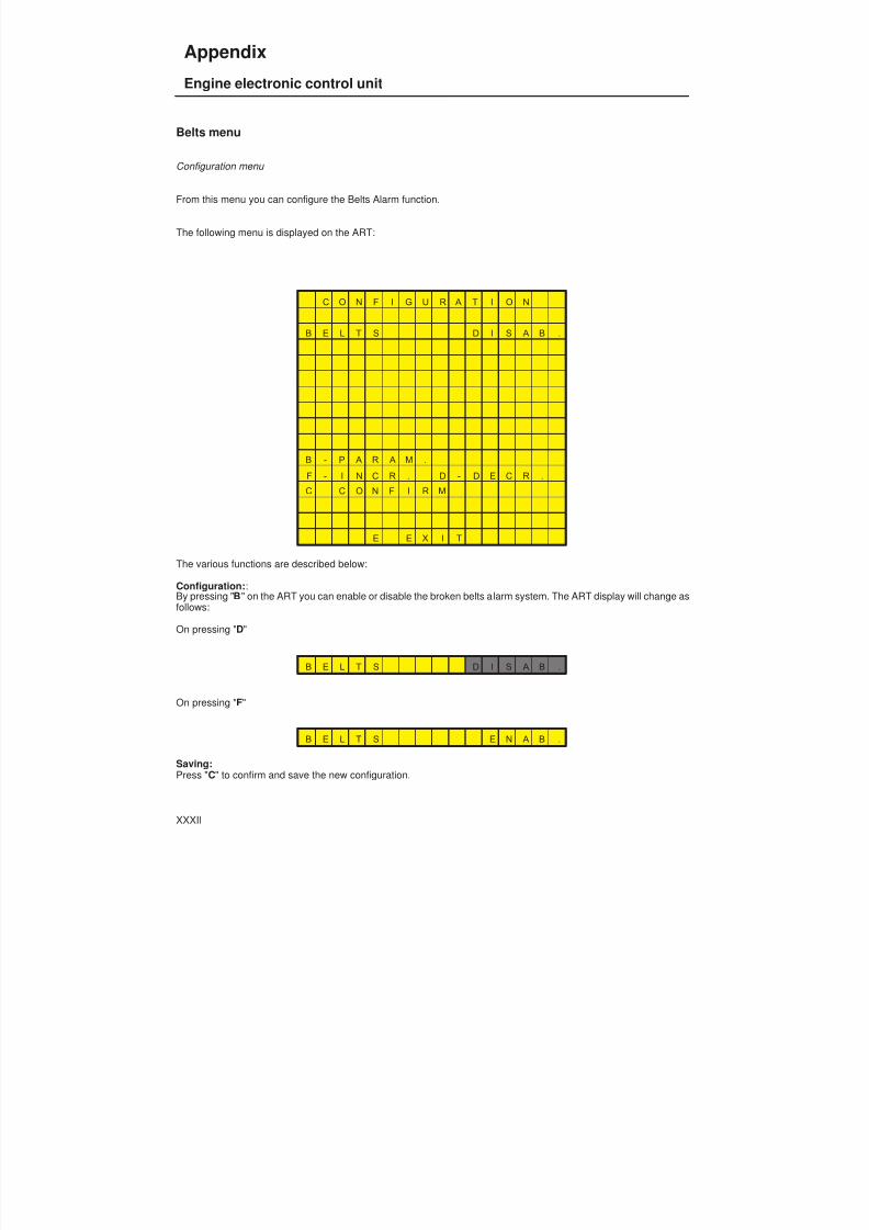
8/19/2019 Agrocompact f60 f70 f80 f90 Repair manual
http://slidepdf.com/reader/full/agrocompact-f60-f70-f80-f90-repair-manual 477/519
Belts menu
Configuration menu
From this menu you can configure the Belts Alarm function.
The following menu is displayed on the ART:
C O N F I G U R A T I O N
B E L T S D I S A B .
B - P A R A M .
F - I N C R . D - D E C R .
C C O N F I R M
E E X I T
The various functions are described below:
Configuration: :By pressing " B " on the ART you can enable or disable the broken belts alarm system. The ART display will change asfollows:
On pressing " D"
B E L T S D I S A B .
On pressing " F"
B E L T S E N A B .
Saving:Press " C" to confirm and save the new configuration.
XXXII
Appendix
Engine electronic control unit
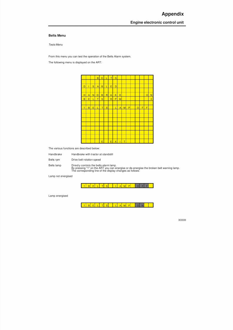
8/19/2019 Agrocompact f60 f70 f80 f90 Repair manual
http://slidepdf.com/reader/full/agrocompact-f60-f70-f80-f90-repair-manual 478/519
Belts Menu
Tests Menu
From this menu you can test the operation of the Belts Alarm system.
The following menu is displayed on the ART:
B E L T S
D I S A B L E D
H A N D B R A K E O N
B E L T S R P M 0
1 B E L T S L A M P O F F
E E X I T
The various functions are described below:
Handbrake Handbrake with tractor at standstill
Belts rpm Drive belt rotation speedBelts lamp Directly controls the belts alarm lamp.
By pressing "1" on the ART you can energise or de-energise the broken belt warning lamp.The corresponding line of the display changes as follows:
Lamp not energised
1 B E L T S L A M P . O F F
Lamp energised
1 B E L T S L A M P O N
XXXIII
Appendix
Engine electronic control unit

8/19/2019 Agrocompact f60 f70 f80 f90 Repair manual
http://slidepdf.com/reader/full/agrocompact-f60-f70-f80-f90-repair-manual 479/519
Belts menu
Monitor menu
B E L T S
D I S A B L E D
H A N D B R A K E O N
B E L T S R P M 0
B E L T S L A M P O F F
E E X I T
The screen is similar to that described in the previous paragraph, the sole difference being that this menu does not pro -vide the possibility to control the various functions.
This screen displays the operating status of the belts alarm system components.
XXXIV
Appendix
Engine electronic control unit

8/19/2019 Agrocompact f60 f70 f80 f90 Repair manual
http://slidepdf.com/reader/full/agrocompact-f60-f70-f80-f90-repair-manual 480/519
Wheels menu
From this menu you can:· configure· monitor
the Wheel Speed system.
The following menu is displayed on the ART:
W H E E L S
1 C O N F I G U R A T I O N
2 M O N I T O R
S E L E C T
E E X I T
The submenus are described below.
XXXV
Appendix
Engine electronic control unit

8/19/2019 Agrocompact f60 f70 f80 f90 Repair manual
http://slidepdf.com/reader/full/agrocompact-f60-f70-f80-f90-repair-manual 481/519
Wheels menu
Configuration menu
From this menu you can configure the Maximum Speed Control function.The following menu is displayed on the ART:
C O N F I G U R A T I O N
L . 3 0 K m / h E N A B .
W H E E L C A L I B , X X X X
A R E S E T B - P A R A M .
F - I N C R . D - D E C R .
C C O N F I R M
E E X I T
The various functions are described below:
by pressing " B" on the ART you can select the parameter to be modified. The ART display changes as follows:
on pressing " B" the selected parameter is highlighted in reverse video
L . 3 0 K m / h E N A B .
press " F" to enable the 30 km/h limit
L . 3 0 K m / h E N A B .
or press " D" to disable the 30 km/h limit
L . 3 0 K m / h D I S A B .
Only if the 30 km/h limit is enabled will it be necessary to calibrate thewheel diameter by following either the putting intoservice procedure or the following instructions.
XXXVI
Appendix
Engine electronic control unit

8/19/2019 Agrocompact f60 f70 f80 f90 Repair manual
http://slidepdf.com/reader/full/agrocompact-f60-f70-f80-f90-repair-manual 482/519
Modification of the wheels parameter:
press " A" on the ART; the value displayed will be set to zero:
W H E E L S C A L . 0 0 0 0
Enter the wheel parameter value K, which is listed in the paragraph "Engine type and Wheels Parameter" in this man -ual.
Press " C " to confirm and save the change.
Then press "E" to exit.
XXXVII
Appendix
Engine electronic control unit
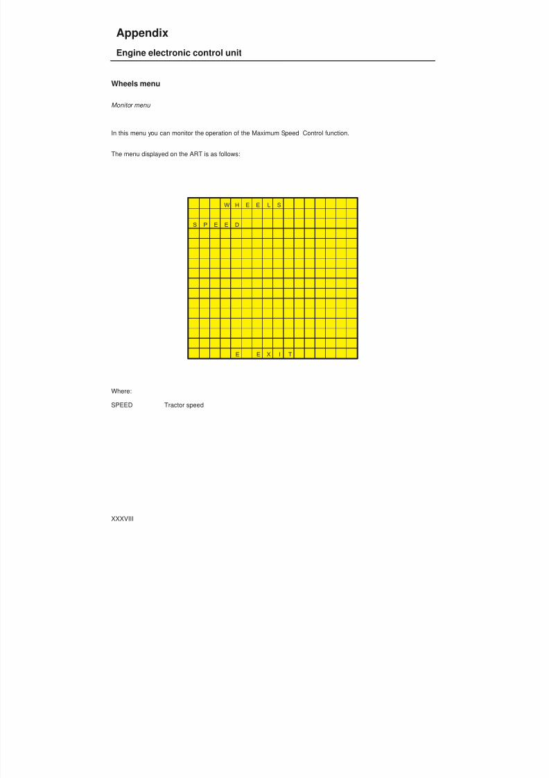
8/19/2019 Agrocompact f60 f70 f80 f90 Repair manual
http://slidepdf.com/reader/full/agrocompact-f60-f70-f80-f90-repair-manual 483/519
Wheels menu
Monitor menu
In this menu you can monitor the operation of the Maximum Speed Control function.
The menu displayed on the ART is as follows:
W H E E L S
S P E E D
E E X I T
Where:
SPEED Tractor speed
XXXVIII
Appendix
Engine electronic control unit
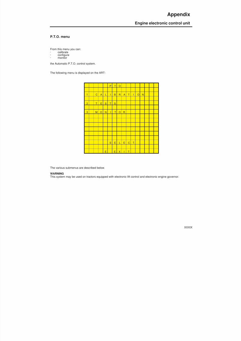
8/19/2019 Agrocompact f60 f70 f80 f90 Repair manual
http://slidepdf.com/reader/full/agrocompact-f60-f70-f80-f90-repair-manual 484/519
P.T.O. menu
From this menu you can:· calibrate· configure· monitor
the Automatic P.T.O. control system.
The following menu is displayed on the ART:
P T O
1 C A L I B R A T I O N
2 T E S T S
3 M O N I T O R
S E L E C T
E E X I T
The various submenus are described below.
WARNINGThis system may be used on tractors equipped with electronic lift control and electronic engine governor.
XXXIX
Appendix
Engine electronic control unit

8/19/2019 Agrocompact f60 f70 f80 f90 Repair manual
http://slidepdf.com/reader/full/agrocompact-f60-f70-f80-f90-repair-manual 485/519
P.T.O. menu
Configuration menu
From this menu you can configure the Automatic P.T.O. function.
The menu is displayed on the ART as follows:
C O N F I G U R A T I O N
L I F T P O S I Z X X X X
M E M O R I S E D X X X X
E E X I T
To configure this function, refer to the putting into service procedure.See point 4 - AUTO P.T.O. calibration.
XL
Appendix
Engine electronic control unit
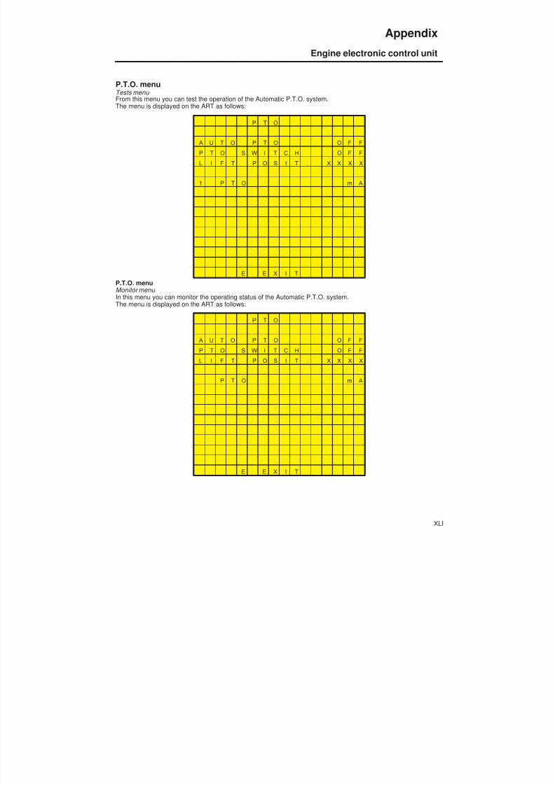
8/19/2019 Agrocompact f60 f70 f80 f90 Repair manual
http://slidepdf.com/reader/full/agrocompact-f60-f70-f80-f90-repair-manual 486/519
P.T.O. menu
Tests menu From this menu you can test the operation of the Automatic P.T.O. system.The menu is displayed on the ART as follows:
P T O
A U T O P T O O F F
P T O S W I T C H O F F
L I F T P O S I T . X X X X
1 P T O m A
E E X I T
P.T.O. menuMonitor menu In this menu you can monitor the operating status of the Automatic P.T.O. system.The menu is displayed on the ART as follows:
P T O
A U T O P T O O F F
P T O S W I T C H O F F
L I F T P O S I T . X X X X
P T O m A
E E X I T
XLI
Appendix
Engine electronic control unit

8/19/2019 Agrocompact f60 f70 f80 f90 Repair manual
http://slidepdf.com/reader/full/agrocompact-f60-f70-f80-f90-repair-manual 487/519
The screen is similar to that described in the previous paragraph, the sole difference being that this menu does notpro -vide the possibility to control the various functions.This screen displays the operating status of the belts alarm system components.
Engine Type/Wheels Constant tables
Engine type configuration
POWER ENGINE
55 A/W-60W 1000.3A7 11
55 A/W-60W 1000.3W2 11
55 A/W-60W 1000.3A2 11
55 A/W-60W 1000.3W1*E 11
63-A/63-W 1000.3AT2 26
63-A/63-W 1000.3WT2 26
67 CV A (3C) 1000.3AT1 29
70 CV W (4C) 1000.3WT1*E 29
70 CV W (3C) 1000.4W4 21
75 CV A (4C-DO) 1000.4A3*E 10
80 CV W (DO) 1000.4W3 24
85 CV A (GO) 1000.4AT1*E 16
85 CV A (DO) 1000.4AT3 46
85 CV W (DO) 1000.4WT4 4487 CV W 1000.4WT1*E 31
Wheels Constant
TYRE model K
320/70 R24 1512
12.4 R24 1442
360/70 R24 144213.6 R24 1390
380/70 R24 1390
12.4 R28 1320
420/70 R24 1320
360/70 R28 1320
13.6 R28 1276
380/70 R28 1276
420/70 R28 1216
380/70 R20 1448
11.2 R24 1448
XLII
Appendix
Engine electronic control unit

8/19/2019 Agrocompact f60 f70 f80 f90 Repair manual
http://slidepdf.com/reader/full/agrocompact-f60-f70-f80-f90-repair-manual 488/519
Fault signalling by flashing of the HOLD indicator light
code ALARM TYPE EFFECT ECU action
1 OVER SPEED - engine switched off - fault signalled
- ENGINE SPEED OVER3200 RPM
2 ACTUATOR - engine switched off - fault signalled
- SHORT CIRCUIT - OPEN CIRCUIT
3 ACCELERATOR PEDAL - normal operation - fault signalled
- SHORT CIRCUIT - OPEN CIRCUIT
4 ENGINE PICKUP -engine switched off - fault signalled
- OPEN CIRCUIT - INTERMITTENT PULSES
5 EEPROM - operationwithdefault parameters - fault signalled
- CHKSUM ERROR - WRITING ERROR
6 WHEELS PICKUP - max engine speed 1500 rpm - fault signalled
- OPEN CIRCUIT - INTERMITTENT PULSES
7 BELTS - handbrake applied:engine switched off and faultsignalled
- no handbrake - fault signalled
- BELT BROKEN - NO PULSES FROM BELT
SENSOR - LOW OIL PRESSURE
AND ENGINE RUNNING
8 HAND THROTTLE - NORMAL OPERATION - FAULT SIGNALLED - SHORT CIRCUIT - OPEN CIRCUIT
9 HML SOLENOID VALVES - NORMAL ENGINE OPERATION - M GEAR - FAULT SIGNALLED
- SHORT CIRCUIT ONSOLENOID
- SOLENOID NOT CONNECTED - COMMAND DOES NOT
CORRESPOND TO OUTPUTSTATUS
- NO VOLTAGE ON HMLCOMMON
XLIII
Appendix
Engine electronic control unit

8/19/2019 Agrocompact f60 f70 f80 f90 Repair manual
http://slidepdf.com/reader/full/agrocompact-f60-f70-f80-f90-repair-manual 489/519
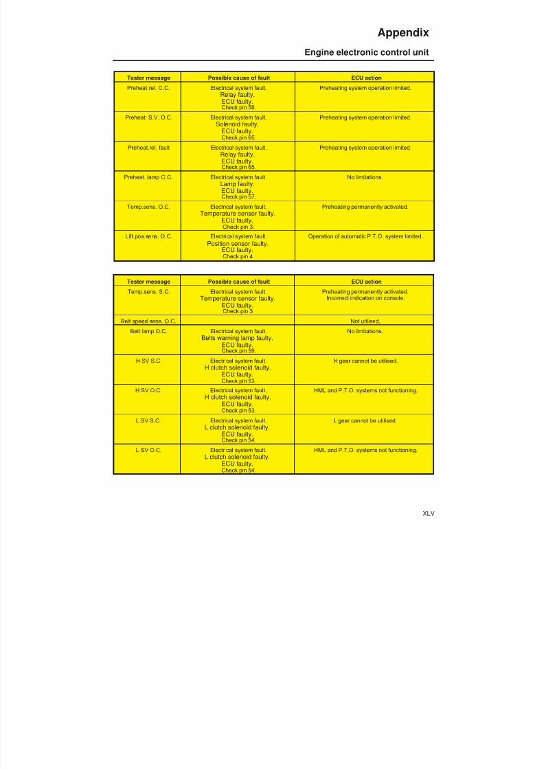
8/19/2019 Agrocompact f60 f70 f80 f90 Repair manual
http://slidepdf.com/reader/full/agrocompact-f60-f70-f80-f90-repair-manual 490/519
Tester message Possible cause of fault ECU action
Preheat.rel. O.C. Electrical system fault.Relay faulty.ECU faulty.Check pin 58.
Preheating system operation limited.
Preheat. S.V. O.C. Electrical system fault.Solenoid faulty.
ECU faulty.Check pin 65.
Preheating system operation limited.
Preheat.rel. fault Electrical system fault.Relay faulty.ECU faulty.Check pin 65.
Preheating system operation limited.
Preheat. lamp O.C. Electrical system fault.
Lamp faulty.ECU faulty.Check pin 57.
No limitations.
Temp.sens. O.C. Electrical system fault.Temperature sensor faulty.
ECU faulty.Check pin 3.
Preheating permanently activated.
Lift.pos.sens. O.C. Electrical system fault.Position sensor faulty.
ECU faulty.Check pin 4.
Operation of automatic P.T.O. system limited.
Tester message Possible cause of fault ECU action
Temp.sens. S.C. Electrical system fault.Temperature sensor faulty.
ECU faulty.Check pin 3.
Preheating permanently activated.Incorrect indication on console.
Belt speed sens. O.C. Not utilised.
Belt lamp O.C. Electrical system fault.Belts warning lamp faulty.
ECU faulty.Check pin 59.
No limitations.
H SV S.C. Electrical system fault.H clutch solenoid faulty.
ECU faulty.Check pin 53.
H gear cannot be utilised.
H SV O.C. Electrical system fault.H clutch solenoid faulty.
ECU faulty.Check pin 53.
HML and P.T.O. systems not functioning.
L SV S.C. Electrical system fault.L clutch solenoid faulty.
ECU faulty.Check pin 54.
L gear cannot be utilised.
L SV O.C. Electrical system fault.L clutch solenoid faulty.
ECU faulty.Check pin 54.
HML and P.T.O. systems not functioning.
XLV
Appendix
Engine electronic control unit
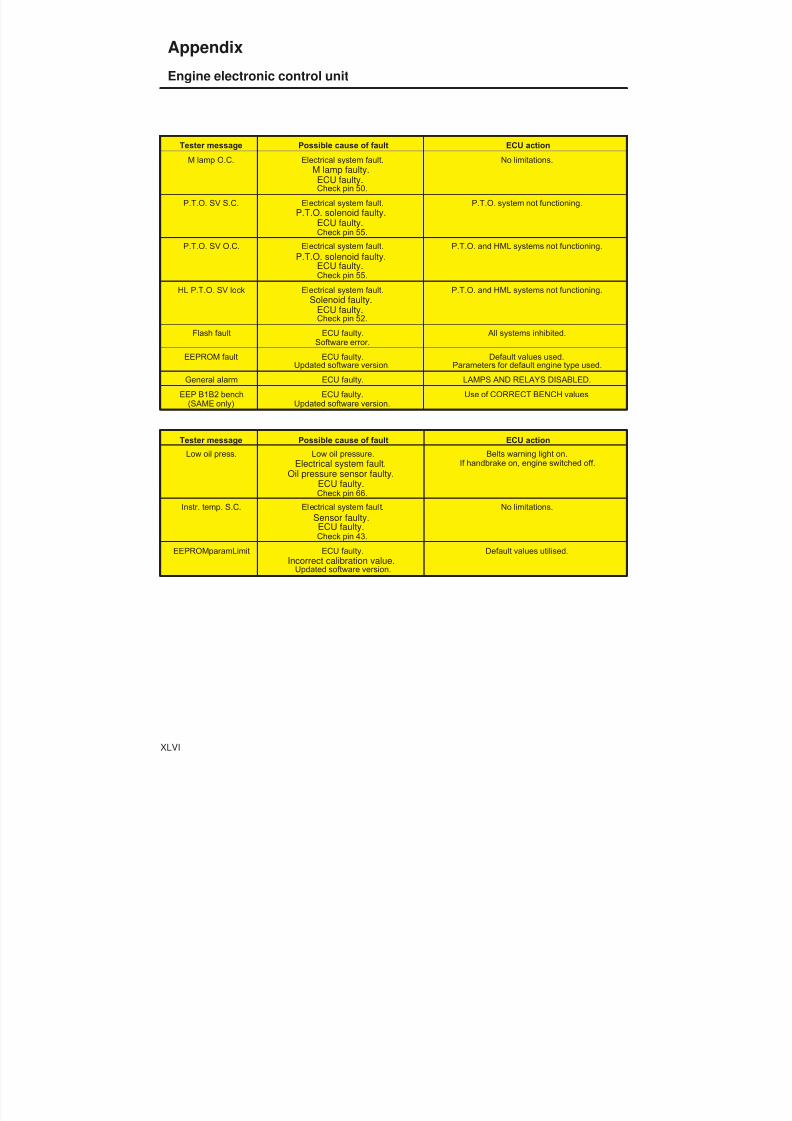
8/19/2019 Agrocompact f60 f70 f80 f90 Repair manual
http://slidepdf.com/reader/full/agrocompact-f60-f70-f80-f90-repair-manual 491/519
Tester message Possible cause of fault ECU action
M lamp O.C. Electrical system fault.M lamp faulty.
ECU faulty.Check pin 50.
No limitations.
P.T.O. SV S.C. Electrical system fault.P.T.O. solenoid faulty.
ECU faulty.Check pin 55.
P.T.O. system not functioning.
P.T.O. SV O.C. Electrical system fault.P.T.O. solenoid faulty.
ECU faulty.Check pin 55.
P.T.O. and HML systems not functioning.
HL P.T.O. SV lock Electrical system fault.Solenoid faulty.
ECU faulty.Check pin 52.
P.T.O. and HML systems not functioning.
Flash fault ECU faulty.Software error.
All systems inhibited.
EEPROM fault ECU faulty.Updated software version.
Default values used.Parameters for default engine type used.
General alarm ECU faulty. LAMPS AND RELAYS DISABLED.
EEP B1B2 bench
(SAME only)
ECU faulty.
Updated software version.
Use of CORRECT BENCH values
Tester message Possible cause of fault ECU action
Low oil press. Low oil pressure.Electrical system fault.
Oil pressure sensor faulty.ECU faulty.Check pin 66.
Belts warning light on.If handbrake on, engine switched off.
Instr. temp. S.C. Electrical system fault.Sensor faulty.
ECU faulty.Check pin 43.
No limitations.
EEPROMparamLimit ECU faulty.Incorrect calibration value.
Updated software version.
Default values utilised.
XLVI
Appendix
Engine electronic control unit

8/19/2019 Agrocompact f60 f70 f80 f90 Repair manual
http://slidepdf.com/reader/full/agrocompact-f60-f70-f80-f90-repair-manual 492/519
POWER LIFT ELECTRONIC CONTROL UNIT
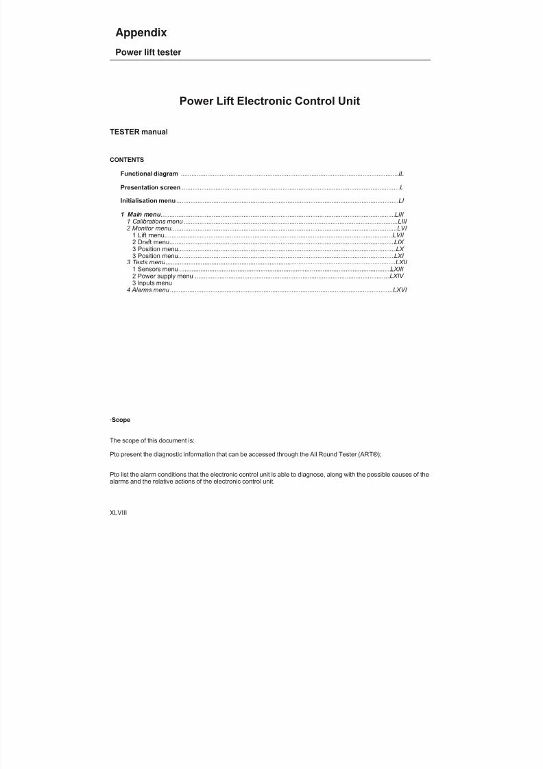
8/19/2019 Agrocompact f60 f70 f80 f90 Repair manual
http://slidepdf.com/reader/full/agrocompact-f60-f70-f80-f90-repair-manual 493/519
Power Lift Electronic Control Unit
TESTER manual
CONTENTS
Functional diagram ............................................................................................................................. IL
Presentation screen ............................................................................................................................. L
Initialisation menu ............................................................................................................................... LI
1 Main menu ...................................................................................................................................... LIII 1 Calibrations menu .......................................................................... ...............................................LIII 2 Monitor menu................................................................................................................................LVI
1 Lift menu................................................................................................................................... LVII 2 Draft menu................................................................................................................................. LIX
3 Position menu............................................................................................................................. LX
3 Position menu............................................................................................................................ LXI 3 Tests menu ....................................................................... ...........................................................LXII
1 Sensors menu ........................................................................... .............................................. LXIII
2 Power supply menu ................................................................................................................ LXIV
3 Inputs menu4 Alarms menu ................................................................................... ...........................................LXVI
·Scope
The scope of this document is:
Pto present the diagnostic information that can be accessed through the All Round Tester (ART®);
Pto list the alarm conditions that the electronic control unit is able to diagnose, along with the possible causes of thealarms and the relative actions of the electronic control unit.
XLVIII
Appendix
Power lift tester
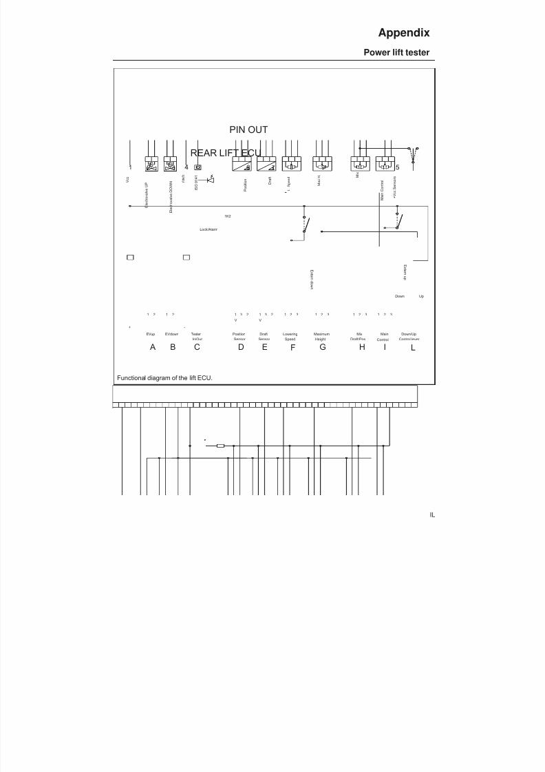
8/19/2019 Agrocompact f60 f70 f80 f90 Repair manual
http://slidepdf.com/reader/full/agrocompact-f60-f70-f80-f90-repair-manual 494/519
REAR LIFT ECU
1 2
EVup
1 2 56 10 11
E l e c t r o v a l v e U
P
+ V c c S e n s o r s
P o s i t i o n G
N D
3 7
Sensor Position
31
V
2
V c c
2
EVdown
1
E l e c t r o v a l v e
D O W N
Sensor Draft
2
V
1 3
D r a f t
SpeedLowering
21 3
L . S
p e e d
MaximumHeight
1 2 3
M a x
H .
MixDraft/Pos
1 2 3
M i x
Main
Control
1 2 3
M a i n
C o n t r o l
8 9
+ -
4 12
I S O 9 1 4 1
Lock/Alarm
1K2
Down/UpControl lever
Tester In/Out
Up
E x t er n u p
E x t er n d own
PIN OUT
Down
A B C D E F G H I L
Functional diagram of the lift ECU.
1 - Vdc A - UP solenoid valve2 - UP solenoid valve B - DOWN solenoid valve3 - DOWN solenoid valve C - Tester IN/OUT4 - GND D - Position sensor 5 - Sensor Vdc E - Draft sensor 6 - Position F - Lowering speed7 - Draft G - Maximum height8 - Speed limit H - DRAFT/POSITION MIX control9 - Maximum height I - Main control10 - Mix L - UP/DOWN control11 - Main control12 - ISO 9141
IL
Appendix
Power lift tester

8/19/2019 Agrocompact f60 f70 f80 f90 Repair manual
http://slidepdf.com/reader/full/agrocompact-f60-f70-f80-f90-repair-manual 495/519
Presentation screen
The presentation screen displays preliminary information about the electronic control unit:
Software version Date of software issue
The screen appears as follows:
L i f t= = = = = = = = = = = = = = = =
S o f t w a r e X . x x x
D a t e d d / m m / y y
P a r a m e t e r s f o r
T R A C T O R x x x
= = = = = = = = = = = = = = = =
= = = = = = = = = = = = = = = =
[ C ] C H A N G E P A R A M .
[ E ] C O N T I N U E
Where: Version software versionDate : date of software issue
The various functions are described below:
Pressing "C"displays the initialisation menu for the tractor type:·lift for tractor 10N·lift for tractor 10S
As described on page 6
Pressing "E"displays the menu described on page
L
Appendix
Power lift tester

8/19/2019 Agrocompact f60 f70 f80 f90 Repair manual
http://slidepdf.com/reader/full/agrocompact-f60-f70-f80-f90-repair-manual 496/519
Initialisation menu
From the Initialisation menu you can configure the lift in accordance wit the type of tractor.
The menu is displayed on the ART as follows:
I N I T I A L I S A T I O N
C u r r e n t
P a r a m e t e r s
f o r 1 0 X
C h a n g e
P a r a m e t e r s
1 - L i f t f o r 1 0 N
2 - L i f t f o r 1 0 S
= = = = = = = = = = = = = = = =
[ C ] C O N T I N U E
Where:
Current parameters defines the configuration currently saved in memory
To change and save the configuration, press "1" or "2".
Press "1" to configure the lift for the 10N tractor.Press "2" to configure the lift for the 10S tractor.
Press "C" to pass to the main menu.
LI
Appendix
Power lift tester
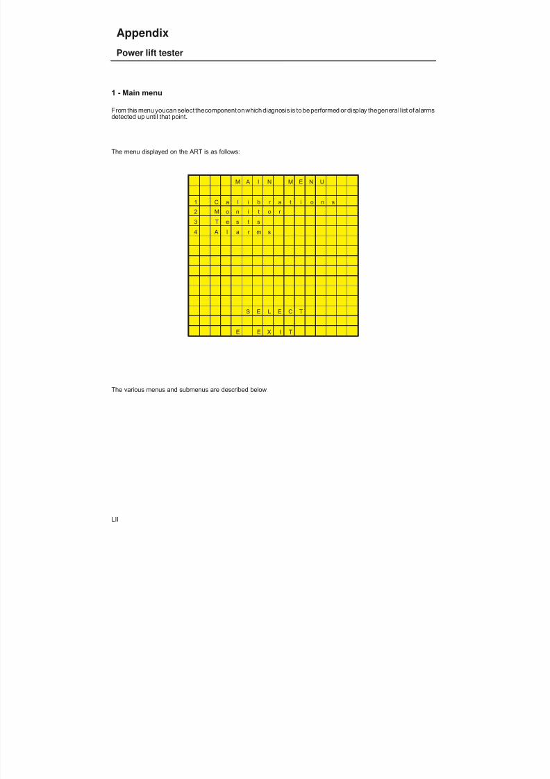
8/19/2019 Agrocompact f60 f70 f80 f90 Repair manual
http://slidepdf.com/reader/full/agrocompact-f60-f70-f80-f90-repair-manual 497/519
1 - Main menu
From this menu youcan select thecomponentonwhich diagnosis is to beperformed or display thegeneral list of alarmsdetected up until that point.
The menu displayed on the ART is as follows:
M A I N M E N U
1 C a l i b r a t i o n s
2 M o n i t o r
3 T e s t s
4 A l a r m s
S E L E C T
E E X I T
The various menus and submenus are described below.
LII
Appendix
Power lift tester

8/19/2019 Agrocompact f60 f70 f80 f90 Repair manual
http://slidepdf.com/reader/full/agrocompact-f60-f70-f80-f90-repair-manual 498/519
1 - Calibrations menu
From this menu you can calibrate the lift system.
The menu displayed on the ART is as follows:
C a l i b r a t i o n s M e n u
- - - - - - - - - - - - - - - -
1 - M a x . h e i g h t
P e r s o n a l i s a t i o n
L i f t i n g s p e e d
2 - L i f t i n g s p e e d
[ E ] E X I T
These operations are to be performed with the lift lock released.
The various calibration functions are described below.
LIII
Appendix
Power lift tester
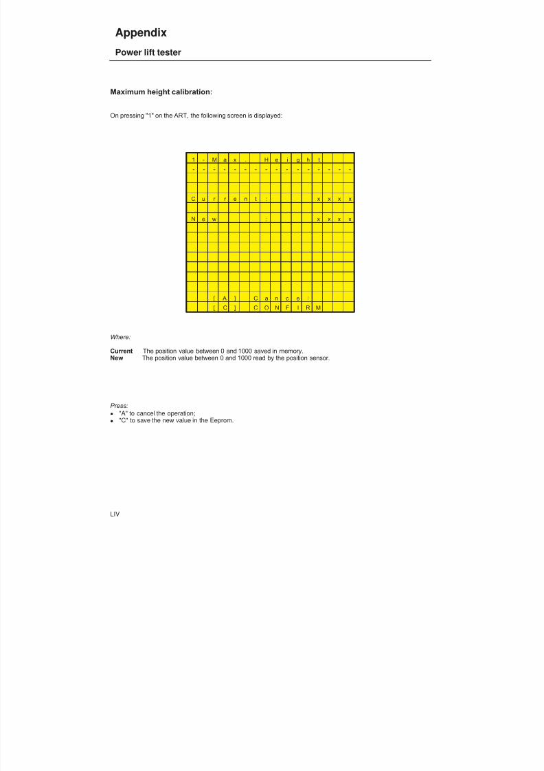
8/19/2019 Agrocompact f60 f70 f80 f90 Repair manual
http://slidepdf.com/reader/full/agrocompact-f60-f70-f80-f90-repair-manual 499/519
Maximum height calibration:
On pressing "1" on the ART, the following screen is displayed:
1 - M a x . H e i g h t
- - - - - - - - - - - - - - - -
C u r r e n t : x x x x
N e w : x x x x
[ A ] C a n c e l
[ C ] C O N F I R M
Where:
Current The position value between 0 and 1000 saved in memory.New The position value between 0 and 1000 read by the position sensor.
Press: "A" to cancel the operation; "C" to save the new value in the Eeprom.
LIV
Appendix
Power lift tester
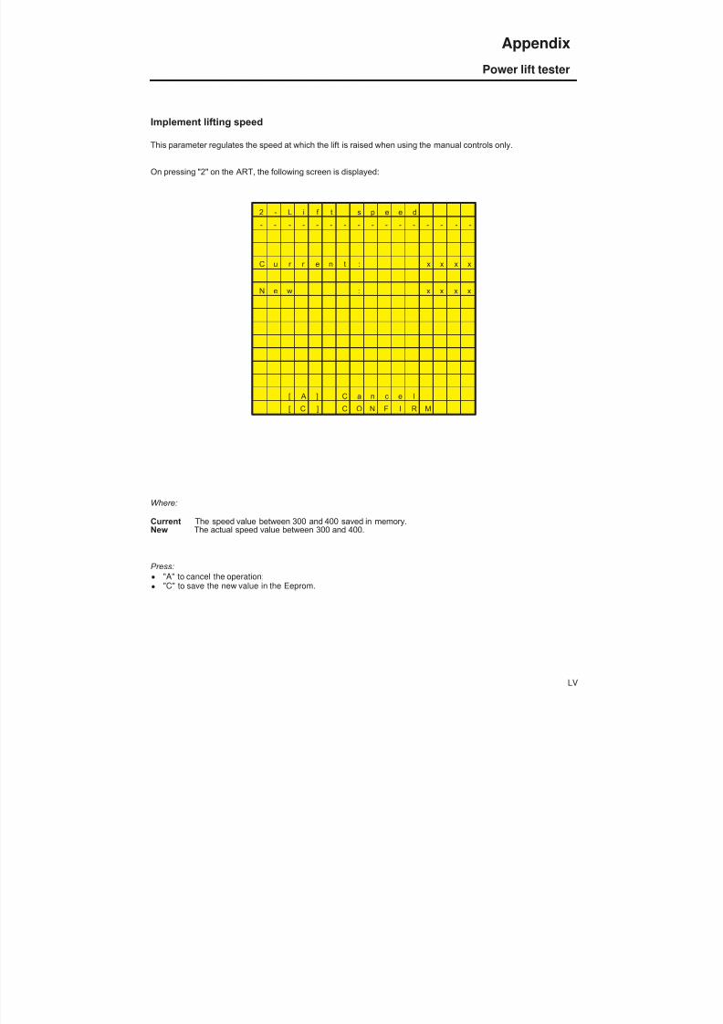
8/19/2019 Agrocompact f60 f70 f80 f90 Repair manual
http://slidepdf.com/reader/full/agrocompact-f60-f70-f80-f90-repair-manual 500/519
Implement lifting speed
This parameter regulates the speed at which the lift is raised when using the manual controls only.
On pressing "2" on the ART, the following screen is displayed:
2 - L i f t s p e e d
- - - - - - - - - - - - - - - -
C u r r e n t : x x x x
N e w : x x x x
[ A ] C a n c e l
[ C ] C O N F I R M
Where:
Current The speed value between 300 and 400 saved in memory.New The actual speed value between 300 and 400.
Press: "A" to cancel the operation; "C" to save the new value in the Eeprom.
LV
Appendix
Power lift tester

8/19/2019 Agrocompact f60 f70 f80 f90 Repair manual
http://slidepdf.com/reader/full/agrocompact-f60-f70-f80-f90-repair-manual 501/519
2 - Monitor menuFrom this menu you can display the operating parameters of the lift system.
The menu displayed on the ART is as follows:
M o n i t o r M e n u
1 L i f t
2 D r a f t
3 P o s i t i o n
[ E ] E X I T
The various functions are described below.
LVI
Appendix
Power lift tester
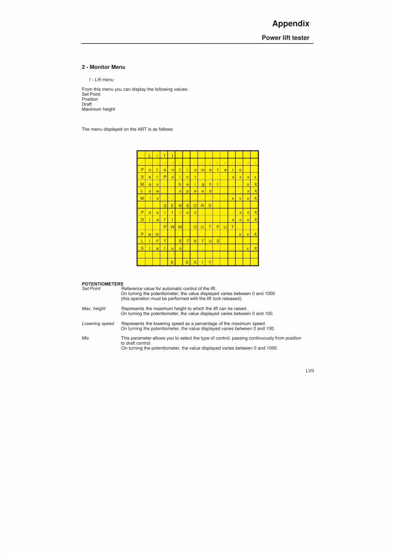
8/19/2019 Agrocompact f60 f70 f80 f90 Repair manual
http://slidepdf.com/reader/full/agrocompact-f60-f70-f80-f90-repair-manual 502/519
2 - Monitor Menu
1 - Lift menu
From this menu you can display the following values:Set PointPositionDraftMaximum height
The menu displayed on the ART is as follows:
L i f t
- - - - - - - - - - - - - - - -
P o t e n t i o m e t e r s
S e t P o i n t . . . . x x x x
M a x . h e i g h t . . . x X
L o w . s p e e d . . . . x X
M i x . . . . . . . . . x x x X
S E N S O R S
P o s i t i o n . . . . . x x X
D r a f t . . . . . . . x x x X
P W M O U T P U T
P w m x x X
L I F T S T A T U S . .
S t a t u s . . . . . . . . x X
E E X I T
POTENTIOMETERSSet Point Reference value for automatic control of the lift.
On turning the potentiometer, the value displayed varies between 0 and 1000(this operation must be performed with the lift lock released).
Max. height Represents the maximum height to which the lift can be raised.On turning the potentiometer, the value displayed varies between 0 and 100.
Lowering speed Represents the lowering speed as a percentage of the maximum speed.On turning the potentiometer, the value displayed varies between 0 and 100.
Mix This parameter allows you to select the type of control, passing continuously from positionto draft control.On turning the potentiometer, the value displayed varies between 0 and 1000.
LVII
Appendix
Power lift tester

8/19/2019 Agrocompact f60 f70 f80 f90 Repair manual
http://slidepdf.com/reader/full/agrocompact-f60-f70-f80-f90-repair-manual 503/519
SENSORSPosition Signal read by the position sensor; values range from 0 to 100.Draft Signal read by the draft sensor; values range from 0 to 1000.
PWM OUTPUTPWM Value that controls the current supplied to the proportional solenoid valves.
Value ranges 290 to 600.
LIFT STATUSStatus Displays the operating status of the lift system.
Press the control button to view the following status informationLOCK lift lockedSTOP lift operative awaiting commandCNTRL lift operating in automatic control modeFLOAT lift in float mode
LVIII
Appendix
Power lift tester

8/19/2019 Agrocompact f60 f70 f80 f90 Repair manual
http://slidepdf.com/reader/full/agrocompact-f60-f70-f80-f90-repair-manual 504/519
2 - Monitor menu2 - Draft menu
From this menu you can display the following values: Pwm Base Up PWM Base Down PWM Max Up PWM Max Down Gain Up GainDown
The menu displayed on the ART is as follows:
D r a f t
- - - - - - - - - - - - - - - -
1 - P W M B a s e U p x x x
2 - P W M B a s e D o w n x x x
3 - P W M M a x U p x x x
4 - P W M M a x D o w n x x x5 - G a i n U p x x
6 - G a i n D o w n x X
[ E ] E X I T
These are the characteristic values of the electronic lift control system. All these values range between 290 and 600.The default values are as follows:
Values 10N 10S
PWM BaseUp 390 360
PWM BaseDown 400 420
PWM MaxUp 600 600
PWM MaxDown 600 600
Gain Up 25 18Gain Down 45 35
LIX
Appendix
Power lift tester
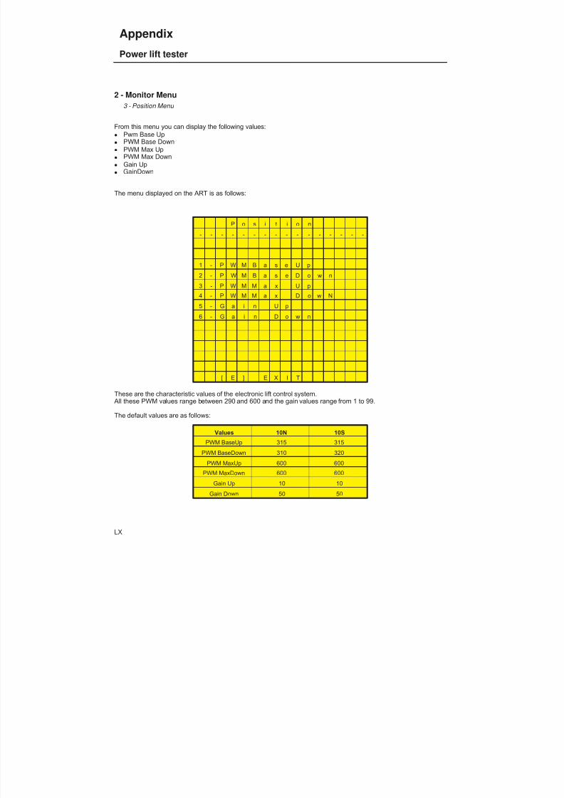
8/19/2019 Agrocompact f60 f70 f80 f90 Repair manual
http://slidepdf.com/reader/full/agrocompact-f60-f70-f80-f90-repair-manual 505/519
2 - Monitor Menu3 - Position Menu
From this menu you can display the following values: Pwm Base Up PWM Base Down PWM Max Up PWM Max Down Gain Up GainDown
The menu displayed on the ART is as follows:
P o s i t i o n
- - - - - - - - - - - - - - - -
1 - P W M B a s e U p
2 - P W M B a s e D o w n
3 - P W M M a x U p
4 - P W M M a x D o w N
5 - G a i n U p
6 - G a i n D o w n
[ E ] E X I T
These are the characteristic values of the electronic lift control system. All these PWM values range between 290 and 600 and the gain values range from 1 to 99.
The default values are as follows:
Values 10N 10S
PWM BaseUp 315 315
PWM BaseDown 310 320
PWM MaxUp 600 600
PWM MaxDown 600 600
Gain Up 10 10Gain Down 50 50
LX
Appendix
Power lift tester
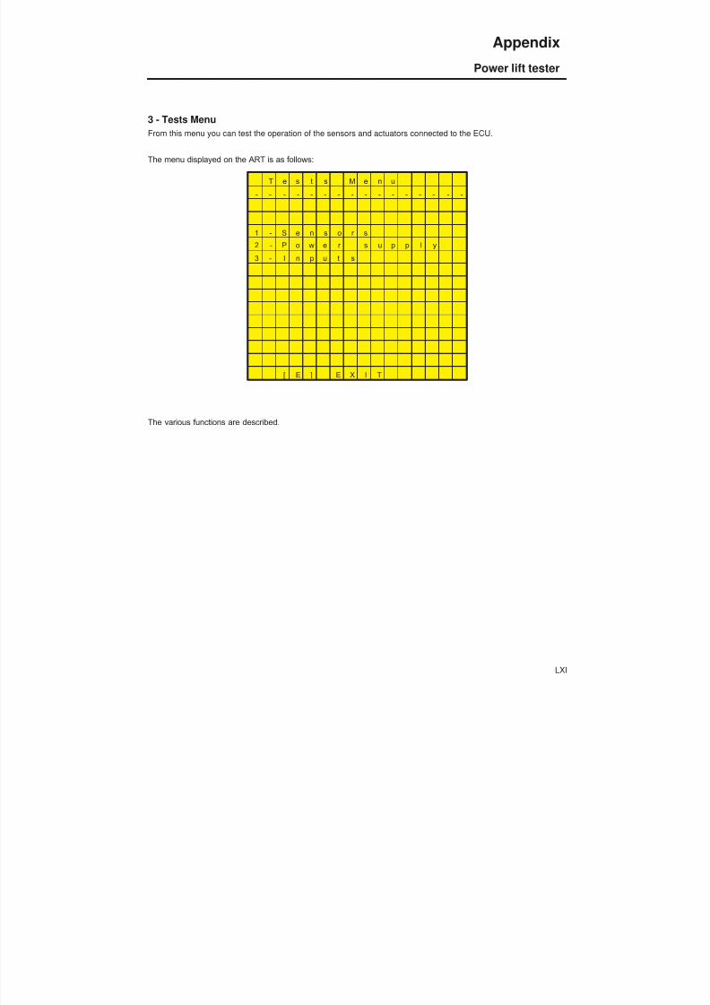
8/19/2019 Agrocompact f60 f70 f80 f90 Repair manual
http://slidepdf.com/reader/full/agrocompact-f60-f70-f80-f90-repair-manual 506/519
3 - Tests MenuFrom this menu you can test the operation of the sensors and actuators connected to the ECU.
The menu displayed on the ART is as follows:
T e s t s M e n u
- - - - - - - - - - - - - - - -
1 - S e n s o r s
2 - P o w e r s u p p l y
3 - I n p u t s
[ E ] E X I T
The various functions are described.
LXI
Appendix
Power lift tester
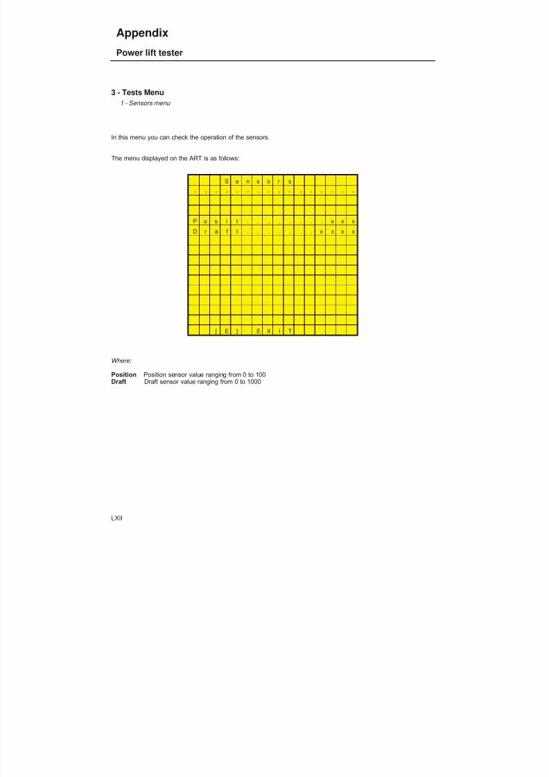
8/19/2019 Agrocompact f60 f70 f80 f90 Repair manual
http://slidepdf.com/reader/full/agrocompact-f60-f70-f80-f90-repair-manual 507/519
3 - Tests Menu1 - Sensors menu
In this menu you can check the operation of the sensors.
The menu displayed on the ART is as follows:
S e n s o r s
- - - - - - - - - - - - - - - -
P o s i t . . . . . . . . x x x
D r a f t . . . . . . . x x x x
[ E ] E X I T
Where:
Position Position sensor value ranging from 0 to 100Draft Draft sensor value ranging from 0 to 1000
LXII
Appendix
Power lift tester
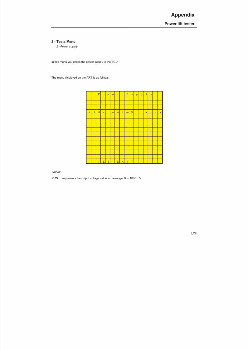
8/19/2019 Agrocompact f60 f70 f80 f90 Repair manual
http://slidepdf.com/reader/full/agrocompact-f60-f70-f80-f90-repair-manual 508/519
3 - Tests Menu2 - Power supply
In this menu you check the power supply to the ECU.
The menu displayed on the ART is as follows:
P o w e r S u p p l y
- - - - - - - - - - - - - - - -
+ 1 0 v o u t m V x x x x
[ E ] E X I T
Where:
+10V represents the output voltage value in the range 0 to 1000 mV.
LXIII
Appendix
Power lift tester

8/19/2019 Agrocompact f60 f70 f80 f90 Repair manual
http://slidepdf.com/reader/full/agrocompact-f60-f70-f80-f90-repair-manual 509/519
3 - Tests menu3 - Inputs
In this menu you can check the operation of the ECU inputs.
The menu displayed on the ART is as follows:
I n p u t s
- - - - - - - - - - - - - - - -
P u s h b u t t o n s
U P / D W
E x t U P / D W
P o t e n t i o m e t e r s
S e t P o i n t . . . . x x x x
M a x . h e i g h t . x x x x
L o w . s p e e d . . x x x xC o n t r o l t y p e. . x x x x
[ E ] E X I T
Where:
Up/Down rocker switch on console
LXIV
Appendix
Power lift tester
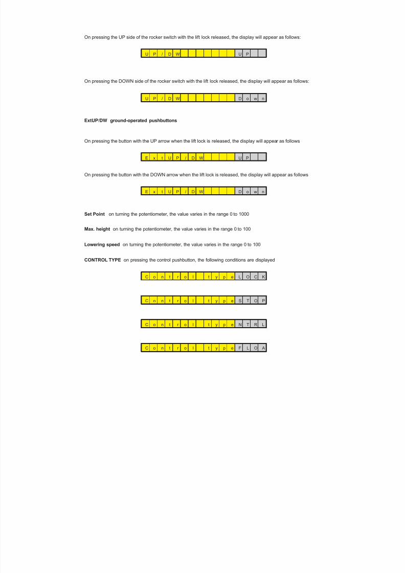
8/19/2019 Agrocompact f60 f70 f80 f90 Repair manual
http://slidepdf.com/reader/full/agrocompact-f60-f70-f80-f90-repair-manual 510/519
On pressing the UP side of the rocker switch with the lift lock released, the display will appear as follows:
U P / D W U P
On pressing the DOWN side of the rocker switch with the lift lock released, the display will appear as follows:
U P / D W D o w n
ExtUP/DW ground-operated pushbuttons
On pressing the button with the UP arrow when the lift lock is released, the display will appear as follows
E x t U P / D W U P
On pressing the button with the DOWN arrow when the lift lock is released, the display will appear as follows
E x t U P / D W D o w n
Set Point on turning the potentiometer, the value varies in the range 0 to 1000
Max. height on turning the potentiometer, the value varies in the range 0 to 100
Lowering speed on turning the potentiometer, the value varies in the range 0 to 100
CONTROL TYPE on pressing the control pushbutton, the following conditions are displayed
C o n t r o l t y p e L O C K
C o n t r o l t y p e S T O P
C o n t r o l t y p e N T R L
C o n t r o l t y p e F L O A
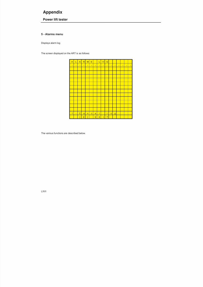
8/19/2019 Agrocompact f60 f70 f80 f90 Repair manual
http://slidepdf.com/reader/full/agrocompact-f60-f70-f80-f90-repair-manual 511/519
5 - Alarms menu
Displays alarm log.
The screen displayed on the ART is as follows:
A L A R M S L O G
- - - - - - - - - - - - - - - -
1 - C a n c e l l o g
[ E ] E X I T
The various functions are described below.
LXVI
Appendix
Power lift tester

8/19/2019 Agrocompact f60 f70 f80 f90 Repair manual
http://slidepdf.com/reader/full/agrocompact-f60-f70-f80-f90-repair-manual 512/519
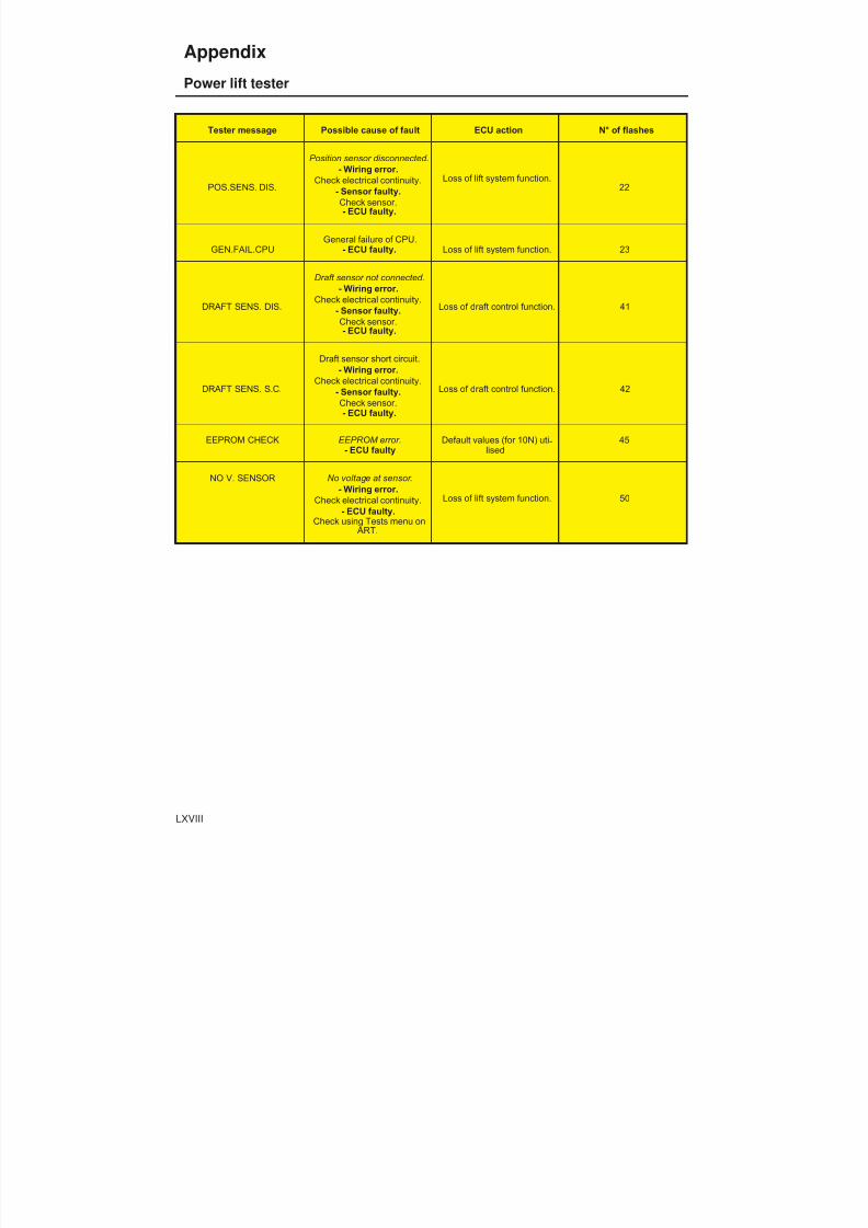
8/19/2019 Agrocompact f60 f70 f80 f90 Repair manual
http://slidepdf.com/reader/full/agrocompact-f60-f70-f80-f90-repair-manual 513/519
Tester message Possible cause of fault ECU action N° of flashes
POS.SENS. DIS.
Position sensor disconnected.- Wiring error.
Check electrical continuity.- Sensor faulty.Check sensor.- ECU faulty.
Loss of lift system function.22
GEN.FAIL.CPUGeneral failure of CPU.
- ECU faulty. Loss of lift system function. 23
DRAFT SENS. DIS.
Draft sensor not connected.- Wiring error.
Check electrical continuity.- Sensor faulty.Check sensor.- ECU faulty.
Loss of draft control function. 41
DRAFT SENS. S.C.
Draft sensor short circuit.- Wiring error.
Check electrical continuity.- Sensor faulty.Check sensor.- ECU faulty.
Loss of draft control function. 42
EEPROM CHECK EEPROM error.- ECU faulty
Default values (for 10N) uti -lised
45
NO V. SENSOR No voltage at sensor.- Wiring error.
Check electrical continuity.- ECU faulty.
Check using Tests menu on ART.
Loss of lift system function. 50
LXVIII
Appendix
Power lift tester

8/19/2019 Agrocompact f60 f70 f80 f90 Repair manual
http://slidepdf.com/reader/full/agrocompact-f60-f70-f80-f90-repair-manual 514/519

8/19/2019 Agrocompact f60 f70 f80 f90 Repair manual
http://slidepdf.com/reader/full/agrocompact-f60-f70-f80-f90-repair-manual 515/519
Der Nachdruck des Textes und der Abbildungen ist, auch auszugsweise, verboten.
La reproduction du présent ouvrage, du texte et des ìllustratìons, mème partìelle est interdite.
Text and illustrations herewith enclosed may not be reproduced, not even in part and by any means.
E’ vietata la riproduzione, anche parziale, del testo e delle illustrazioni.
Se prohibe la reproducciòn total o parcial del texto y de las ilustraciones.
A proibida a reproduçào, até mesmo parcial, do texto e das ilustracòes.
Der zeitliche Unterschied zwischen der Aktualisierung der Druckschriften und der Durchführung technischer Verände -rungen (die ständig vorgenommen werden, um immer hochwertigere Erzeugnisse auf den Markt zu bringen) erfordernaus Gründen der Korrektheit des Hinweises, dass die in dieser Ausgabe enthaltenen Daten jederzeit geändert werdenkönnen und deshalb unverbindlich sind.
Le temps qui s’écoule entre la mise à jour en impression et les modifications techniques (ces dernières changeant con -tinuellement afin d’offrir aux utilisateurs des produits toujours plus qualifiés) nous oblige a vous signaler que lesdonnéesde la présente publication pourraient êtresusceptiblesde variations.Elles sont donnéessans engagementdenotre part.
Because of the possible time lag between the introduction of technical modifications (an on-going process the aim ofwhich is to offer products which are being continually improved) and the latest update of the manual, we must point out,for the sake of correctness,that the data contained in this edition are liable to change at any time and are therefore notbinding.
La differenza tra i tempi di aggiornamento in stampa e i tempi delle modifiche tecniche (variando queste ultime conti -nuamente, ciò al fine di offrire prodotti sempre più qualificati) impongono di dichiarare, per correttezza, che i dati con -tenuti nella presenteedizione sono suscettibili di variazione in qualsiasi momento e chequindinonsono impegnativi.
La diferencia entre los tiempos necesarios para poner al dia la impresiòn y los tiempos de las modificaciones tècnicas(las que se verifican continuamente, con el objeto de ofrecer productos cada vez màs calificados) nos imponendeclarar, por corrección, que los datos contenidos en la presente ediciòn estàn sujetos a variaciones en cualquier mo -mento y que portanto no son obligativos.
A diferença entre os tempos necessãrrios para actualizar a impressão e os tempos das modificacões técnicas (que severificam continuamente, a fim de oferecer um produto cada vez mais qualificado), obrigam-nos a declarar, que os da -doscontidos neste manuel sãosusceptiveisde variacão em qualquer momentoe que portanto nãosãovinculatórios.

8/19/2019 Agrocompact f60 f70 f80 f90 Repair manual
http://slidepdf.com/reader/full/agrocompact-f60-f70-f80-f90-repair-manual 516/519
NOTES
8/19/2019 Agrocompact f60 f70 f80 f90 Repair manual
http://slidepdf.com/reader/full/agrocompact-f60-f70-f80-f90-repair-manual 517/519
NOTES
05 - 2001 cod. 307.1069.3.6By Personal computing Technical Publications Dep.

8/19/2019 Agrocompact f60 f70 f80 f90 Repair manual
http://slidepdf.com/reader/full/agrocompact-f60-f70-f80-f90-repair-manual 518/519

8/19/2019 Agrocompact f60 f70 f80 f90 Repair manual
http://slidepdf.com/reader/full/agrocompact-f60-f70-f80-f90-repair-manual 519/519