AGREEMENT - Početna · ROU Autoritatea Na ional pentru Administrare úi Reglementare în Comunica...
238
AGREEMENT between the Administrations of Austria, Belgium, the Czech Republic, Germany, France, Hungary, the Netherlands, Croatia, Italy, Liechtenstein, Lithuania, Luxembourg, Poland, Romania, the Slovak Republic, Slovenia and Switzerland on the co-ordination of frequencies between 29.7 MHz and 43.5 GHz for the fixed service and the land mobile service. (HCM Agreement) Budapest, 6 November 2014
Transcript of AGREEMENT - Početna · ROU Autoritatea Na ional pentru Administrare úi Reglementare în Comunica...

AGREEMENT
between the Administrations of
Austria, Belgium,
the Czech Republic, Germany, France,
Hungary, the Netherlands,
Croatia, Italy,
Liechtenstein, Lithuania,
Luxembourg, Poland,
Romania, the Slovak Republic,
Slovenia and
Switzerland
on the co-ordination of frequencies between 29.7 MHz and 43.5 GHz for the fixed service and the land mobile service.
(HCM Agreement)
Budapest, 6 November 2014

page 2 of 20
Table of contents
1 Definitions
2 General
3 Technical provisions
4 Procedures
5 Report of harmful interference
6 Revision of this Agreement
7 Accession to this Agreement
8 Withdrawal from this Agreement
9 Status of co-ordinations prior to this Agreement
10 Languages of this Agreement
11 Entry into force of this Agreement
12 Revocation of the Agreement agreed by correspondence in 2014
Preamble
Article
Article
Article
Article
Article
Article
Article
Article
Article
Article
Article
Article

page 3 of 20
Annexes
Part A
Annexes related to the Land Mobile Service
Annex 1 Maximum permissible interference field strengths and maximum cross-border
ranges of harmful interference for frequencies requiring co-ordination in the Land Mobile Service
Annex 2A Data exchange in the Land Mobile Service Annex 3A Determination of the correction factor for the permissible interference field
strength at different nominal frequencies in the Land Mobile Service Annex 4 Propagation curves in the Land Mobile Service Annex 5 Determination of the interference field strength in the Land Mobile Service Annex 6 Coding instructions for antenna diagrams in the Land Mobile Service Annex 7 Provisions on measurement procedures in the Fixed Service and the Land
Mobile Service Annex 8A Method for combining the horizontal and vertical antenna patterns for the Land
Mobile Service
Part B
Annexes related to the Fixed Service
Annex 2B Data exchange in the Fixed Service Annex 3B Determination of the Masks Discrimination and the Net Filter Discrimination in
the Fixed Service Annex 7 Provisions on measurement procedures in the Fixed Service and the Land
Mobile Service Annex 8B Method for combining the horizontal and vertical antenna patterns for the
Fixed Service Annex 9 Threshold Degradation in the Fixed Service Annex 10 Determination of the basic transmission loss in the Fixed Service Annex 11 Trigger for co-ordination in the Fixed Service

page 4 of 20
Preamble
The representatives of the administrations of Austria, Belgium, the Czech Republic, Ger-many, France, Hungary, the Netherlands, Croatia, Italy, Liechtenstein, Lithuania, Luxem-bourg, Poland, Romania, the Slovak Republic, Slovenia and Switzerland have concluded the present Agreement, under Article 6 of the Radio Regulations, on the co-ordination of frequencies between 29.7 MHz and 43.5 GHz for the purposes of preventing mutual harmful interference to the Fixed and Land Mobile Services and optimising the use of the frequency spectrum above all on the basis of mutual agreements.
This Agreement is referred to as HCM Agreement (Budapest 2014).

page 5 of 20
Article 1
1 Definitions
The definitions used in this Agreement shall be those of Article 1 of the Radio Regulations as well as those listed in this Section.
1.1 Administrations
AUT Bundesministerium für Verkehr, Innovation und Technologie (Federal Ministry for Transport, Innovation and Technology)
BEL Belgisch Instituut voor Postdiensten en Telecommunicatie Institut Belge des services Postaux et des Télécommunications (Belgian Institute for Postal services and Telecommunications)
CZE Český telekomunikační úřad (Czech Telecommunication Office)
D Bundesnetzagentur für Elektrizität, Gas, Telekommunikation, Post und Eisenbahnen (Federal Network Agency for Electricity, Gas, Telecommunications, Post and Railway)
F Agence Nationale des Fréquences (National Frequencies Agency )
HNG Nemzeti Média- és Hírközlési Hatóság (National Media and Infocommunications Authority)
HOL Agentschap Telecom (Radio Communications Agency Netherlands)
HRV Hrvatska regulatorma agencija za mrežne djelatnosti (Croatian Regulatory Authority for Network Industries)
I Ministero dello Sviluppo Economico – Dipartimento Comunicazioni (The Ministry of Economic Development – Department of Communication)
LIE Amt für Kommunikation (Office for Communications)
LTU Lietuvos Respublikos ryšių reguliavimo tarnyba (Communications Regulatory Authority of the Republic of Lithuania)
LUX Institut Luxembourgeois de Régulation (Luxembourg Regulator)
POL Urząd Komunikacji Elektronicznej (Office of Electronic Communications)
ROU Autoritatea Naţională pentru Administrare şi Reglementare în Comunicaţii (National Authority for Management and Regulation in Communications of Romania)

page 6 of 20
SVK Úrad pre reguláciu elektronických komunikácií a poštových služieb (Regulatory Authority for Electronic Communications and Postal Services)
SVN Agencija za komunkacijska omrežja in storitve Republike Slovenije
(Agency for communication networks and services of the Republic of Slovenia)
SUI Bundesamt für Kommunikation Office fédéral de la communication (Federal Office of Communications)
1.2 Frequencies
1.2.1 Frequencies in the bands listed below for the Land Mobile Service in the countries concerned shall be co-ordinated under the terms of this Agreement.
29,7 - 47 MHz 68 - 74,8 MHz 75,2 - 87,5 MHz
146 - 149,9 MHz 150,05 - 174 MHz 380 - 385 MHz for emergency and security systems only 390 - 395 MHz for emergency and security systems only 406,1 - 430 MHz 440 - 470 MHz 790 - 960 MHz
1710 - 1785 MHz for GSM 1800 systems only 1805 - 1880 MHz for GSM 1800 systems only 1900 - 1980 MHz for UMTS/IMT-2000 terrestrial systems only 2010 - 2025 MHz for UMTS/IMT-2000 terrestrial systems only 2110 - 2170 MHz for UMTS/IMT-2000 terrestrial systems only 2500 - 2690 MHz
1.2.2 For the Land Mobile Service in frequency bands other than those defined in 1.2.1
and for all other services in these frequency bands, the co-ordination procedure set out in this Agreement may be used, and, if necessary, the technical parameters shall be agreed separately.

page 7 of 20
1.2.3 Frequencies in the bands listed below, used in the countries concerned for the Fixed Service shall be co-ordinated under the terms of this Agreement.
1350 - 1375 MHz 10,15 - 10,65 GHz 1375 - 1400 MHz 10,7 - 11,7 GHz 1427 - 1452 MHz 12,75 - 13,25 GHz 1492 - 1525 MHz 14,5 - 14,62 GHz 2025 - 2110 MHz 15,23 - 15,35 GHz 2200 - 2290 MHz 17,7 - 19,7 GHz 3410 - 3600 MHz 22 - 22,6 GHz 3600 - 4200 MHz 23 - 23,6 GHz 5925 - 6425 MHz 24,5 - 26,5 GHz 6425 - 7125 MHz 27,5 - 29,5 GHz 7125 - 7725 MHz 31,8 - 33,4 GHz 7725 - 7975 MHz 37 - 39,5 GHz 8025 - 8275 MHz 40,5 - 43,5 GHz 8275 - 8500 MHz
1.2.3.1 The co-ordination procedure laid down in this Agreement for the Fixed Service is
only valid if in both countries involved in the co-ordination process the respective frequency band is allocated to the Fixed Service and the respective frequency falls under the responsibility of the Administrations.
1.2.4 For frequencies below 1 GHz and listed under 1.2.1, used in the countries con-cerned for the Fixed Service, the co-ordination procedure and the technical provi-sions set out in this Agreement for the Land Mobile Service shall be used.
1.2.5 For frequencies above 1 GHz used in the countries concerned for the Fixed Service in frequency bands other than those listed in the frequency table given in paragraph 1.2.3, the co-ordination procedure set out in this Agreement for the Fixed Service may be used, and, if necessary, the technical parameters shall be agreed sepa-rately.
1.2.6 Short Range Devices (SRDs) as defined in ERC/REC 70-03 are not subject to this Agreement.
1.3 Frequency categories
1.3.1 Frequencies requiring co-ordination Frequencies which Administrations are required to co-ordinate with the other Administrations affected (see 1.6) before a station is put into service.
1.3.2 Preferential frequencies Frequencies which the Administrations concerned may assign, without prior co-ordi-nation, on the basis of bi- or multilateral agreements under the terms laid down therein.
1.3.3 Shared frequencies Frequencies which may be shared without prior co-ordination, on the basis of bi- or multilateral agreements under the terms laid down therein.

page 8 of 20
1.3.4 Frequencies for planned radio communication networks Frequencies which the Administrations must co-ordinate with a view to the subse-quent introduction of coherent radio communication networks, where the number of locations multiplied by the number of frequencies exceeds 36.
1.3.5 Frequencies used on the basis of geographical network plans Frequencies used for the Land Mobile Service, in the countries concerned on the basis of a geographical network plan prepared and adopted in advance, taking into account the technical characteristics set out in that plan.
1.3.6 Frequencies using preferential codes Frequencies which the Administrations concerned may assign, without prior co-ordi-nation, on the basis of bi- or multilateral agreements under the terms laid down therein.
1.3.7 Frequencies used on the basis of arrangements between operators Frequencies laid down in arrangements between operators may be used without prior co-ordination, on the condition that there is an existing agreement signed by the Administrations concerned authorising such arrangements. These arrangements between operators may also include the use of the codes.
A copy of each bi- or multilateral agreement mentioned in Sections 1.3.2, 1.3.3, 1.3.6 and 1.3.7, if not confidential, should be sent in electronic form to the Managing Administration which will inform all other Administrations by placing it on the server.
1.4 Frequency Register
The Frequency Register shall be made up of lists set out by every Administration indicating its co-ordinated frequencies, its assigned preferential frequencies, its shared frequencies, its frequencies co-ordinated for planned radio communication networks, and its frequencies used on the basis of geographical network plans and frequencies using preferential codes. A list of the details to be included in the Fre-quency Register is given in Annex 2A and Annex 2B. All frequency assignments in this register shall be protected according to their status of co-ordination. There are as many lists as affected countries.
1.5 Harmful interference
Harmful interference shall be construed as any emission which causes serious deg-radation in the quality of the traffic of a radio communication service, or repeatedly disrupts or interrupts that service by exceeding the maximum permissible interfer-ence field strength specified for the Land Mobile Service in Annex 1 or in the case of the Fixed Service exceeding the maximum permissible threshold degradation in Annex 9.

page 9 of 20
1.6 Administration affected
Any Administration whose station could suffer from harmful interference as a result of the planned use of a frequency, or whose station could cause harmful interfer-ence to a planned receiving station of the requesting Administration.
1.7 HCM Programs
1.7.1 The HCM (Harmonised Calculation Method) Programs are programs developed for the harmonised application of the calculation methods as provided in the Annexes of this Agreement. The Technical Working Group HCM was given the task by the administrations to manage the HCM Programs for the Mobile Service and the Fixed Service. Each ‘HCM Program’ means the source code, the DLL, the test program (*.EXE) and the program documentation. Every Administration is free to use the source code, the DLL, or the test program. In case of dispute, the test program will be used as a reference.
The managing Administration is responsible for the maintenance and registration of the HCM server.
All the provisions of this Agreement will apply, making use of the HCM program for the respective service, using a topo-database and border lines.
The existing database and border lines available on the HCM-server and further described in the user manual are a basis for bi- or multilateral agreements.
If more detailed topographical database and border line data are needed, they shall be mutually agreed between Administrations carrying out co-ordinations with each other.
1.7.2 A new version of a HCM program has to be implemented by all Administrations at the same point in time to avoid keeping different versions for different neighbouring countries. Because the HCM software is only a subroutine, this subroutine has to be implemented in national surrounding programs. The following procedure is set up:
The Managing Administration announces new HCM program versions and the exact date of the implementation of them. The new HCM program is put on the data server of this Agreement for download. The version history is updated.
If an error is reported, TWG may give instructions to correct this error and task the relevant sub working group to provide a new program version.
The implementation phase is one month.
1.7.2.1 If modifications are done to the interface to the surrounding program (modifications of the surrounding program are required), a grace period of one year after the official announcement of the new version is granted.
1.7.3 For the harmonized application of the calculation method laid down in the Annexes to this Agreement new versions of the HCM programs will be developed.

page 10 of 20
1.8 Data Exchange
1.8.1 If modifications are done to the Annex 2A or Annex 2B (modifications of the surrounding program are required), a grace period of one year after the official announcement of the new version is granted.

page 11 of 20
Article 2
2 General
2.1 This Agreement shall in no way affect the rights and obligations of the Administra-tions arising from the Constitution and Convention of the International Telecommuni-cation Union (ITU), the administrative Regulations and Agreements concluded within the framework of the ITU as well as other pertinent inter-governmental agreements.
2.2 Administrations shall assign frequencies exclusively in accordance with the provi-sions of this Agreement. If co-ordination is required, it shall be done prior to the put-ting into operation of the radio station affected.
2.3 If necessary, the Administrations may agree on provisions that are different from or supplementary to the provisions of this Agreement, which, however, must not adversely affect Administrations that are not concerned.
2.4 The Fixed and Land Mobile Services which do not come under the responsibility of the Administrations or which usage is restricted for national defence purposes or for which information is not available due to security reasons shall not be governed by the provisions of this Agreement unless otherwise provided for.
2.5 In the case of the Land Mobile Service the effective radiated power and the effective antenna height of stations shall be chosen so that their range is confined to the area to be covered. Excessive antenna heights and transmitter outputs shall be avoided by using several locations and low effective antenna heights. Directional antennas shall be used in order to minimise the potential of interference to the neighbouring country. The maximum cross-border ranges of harmful interference for frequencies requiring co-ordination are given in Annex 1.
2.6 The effective radiated power and the antenna height of stations in the Fixed Service shall be chosen according to the radio links lengths and the required quality of ser-vice. Excessive antenna heights, excessive transmitter outputs and too low antenna directivities shall be avoided in order to minimise the potential of interference to the country affected.

page 12 of 20
Article 3
3 Technical provisions
The request for co-ordination of a station and the evaluation of this request shall be made in accordance with the following technical provisions:
3.1 In case of the Land Mobile Service the maximum permissible interference field strength is given in Annex 1. In case of the Fixed Service, the maximum permissible threshold degradation is given in Annex 9.
3.2 Where in the case of the Land Mobile Service the nominal frequencies are different, the permissible interference field strength shall be increased as indicated in Annex 3A. In case of the Fixed Service the interference level at the receiver input shall be decreased according to Annex 9 by the Masks Discrimination (MD) and the Net Filter Discrimination (NFD) as given in Annex 3B.
3.3 The interference field strength shall be determined in the case of the Land Mobile Service in accordance with Annex 5. In the case of the Fixed Service, the threshold degradation shall be determined using Annex 9 where the basic transmission loss is calculated in accordance with Annex 10.
3.4 Administrations may agree to apply parameters other than the set values.

page 13 of 20
Article 4
4 Procedures
4.1 Frequencies requiring co-ordination
In the case of the Land Mobile Service a transmitting frequency shall be co-ordi-nated if the transmitter produces a field strength, at the border of the country of the Administration affected, which, at a height of 10 m above ground level, exceeds the maximum permissible interference field strength as defined in Annex 1. A receiving frequency shall be co-ordinated if the receiver requires protection.
It is strongly recommended to co-ordinate radio-relay links in the Fixed Service if the shortest distance from the border of at least one station is less or equal to the one defined in Annex 11. All stations which may cause harmful interference to stations in other countries or need protection shall be co-ordinated regardless of the distance.
4.1.1 Any Administration wishing to take into operation a station shall circulate a request for co-ordination to all Administrations affected for their comment. This request shall include the characteristics in accordance with Annex 2A and Annex 2B.
4.1.2 If, for the purpose of technically evaluating this request, the Administration affected requires information that is lacking or needs to be supplemented in accordance with Annex 2A and Annex 2B, it shall ask for this information within 30 days upon receipt of the request for co-ordination. After this request, complete information concerning a request for co-ordination shall be sent by the requesting administration within 30 days, otherwise the coordination request shall be deemed null and void.
4.1.3 Having received complete information concerning a request for co-ordination, the Administration affected shall evaluate this information in accordance with the provi-sions of this Agreement. It shall notify the requesting Administration of the outcome within 45 days.
4.1.4 If the Administration which initiated the co-ordination procedure does not receive a reply within 45 days, it may send a reminder. The Administrations affected shall respond to this reminder within 20 days.
4.1.5 If the Administration affected again fails to respond within the period fixed under Section 4.1.4, it shall be deemed to have given its consent, and the station shall be considered co-ordinated.
4.1.6 The periods specified under Sections 4.1.3 and 4.1.4 may be changed by mutual consent.
4.1.7 Any co-ordinated frequency assignment shall be notified to the Administrations affected as soon as the corresponding station is put into operation but not later than 180 days upon approval. Following such notification of the assignment, this assign-ment shall be updated in the Frequency Register. If no notification of assignment is given within 180 days, the Administration affected shall send a reminder to the Administration that has asked for co-ordination. If no notification of assignment is given within another 30 days, the request for co-ordina-tion shall be deemed null and void. No notification shall be required if the frequency registers are exchanged semi-annually in accordance with Section 4.9.1.

page 14 of 20
4.1.8 The Administration wishing to change the technical characteristics of stations regis-tered in the Frequency Register, shall notify the Administrations affected of its inten-tions. Co-ordination shall be required if this change causes the probability of inter-ference to increase in the affected country. If the situation remains unchanged with regard to interference or if it improves, the Administrations affected shall only be informed of such a change. The entry in the Frequency Register shall be corrected accordingly.
4.1.9 In special cases, the Administrations may assign frequencies for temporary use (up to 45 days) without co-ordination provided this does not cause harmful interference to co-ordinated stations. As soon as possible, the Administration affected shall be notified of the planned taking into operation. Such stations shall immediately be taken out of operation if they cause harmful interference to co-ordinated stations of the affected country. These assignments shall be made on preferential frequencies as far as possible.
4.1.10 If an assignment is no longer in force, the competent Administration shall notify the affected Administration within three months and the entry in the Frequency Register has to be deleted.
4.2 Preferential frequencies
4.2.1 Frequencies in the frequency bands specified in Section 1.2 may be defined by prior bi- or multilateral agreements concluded in the framework of this agreement as pref-erential frequencies for given Administrations.
4.2.2 The Administration which has been granted a preferential right may put stations operating on preferential frequencies within the terms of the relevant bi- or multilat-eral agreements into use without prior co-ordination. If the conditions for the protection of the receiver in the mobile service are not defined in bi- or multilateral agreements, section 2.2 of Annex 1 will apply.
4.2.3 Preferential frequencies granted to an Administration shall have priority rights over assignments made to other Administrations concerned.
4.2.4 The entry into service of stations using preferential frequencies shall be notified to the Administrations affected, unless otherwise laid down in bi- or multilateral agree-ments. The notification shall include the characteristics as set out in Annex 2A and Annex 2B. These frequencies and their technical characteristics shall be entered with status “P” into the Frequency Register. No response to such a notification is required.
4.2.5 Preferential frequencies to be assigned on conditions other than those agreed in bi-or multilateral agreements mentioned in Section 1.3.2 shall be co-ordinated in accordance with Section 4.1.
4.2.6 Following a positive co-ordination procedure in accordance with Section 4.1, Admini-strations may bring into use another Administration's preferential frequencies. These shall have the same rights as frequencies co-ordinated in accordance with Section 4.1.
4.2.7 If the existing radio networks of one Administration cause harmful interference to the stations operated by another Administration on frequencies to which it has a prefer-ential right, or if, in particular cases, frequency assignments not enjoying preferential rights have to be adjusted, the Administrations concerned shall determine the tran-sition period by mutual consent.

page 15 of 20
4.3 Frequencies for planned radio communication networks
4.3.1 Prior to the co-ordination of a planned radio communication network the Administra-tions may embark on a consultative procedure in order to facilitate the taking into operation of this new network. The request for consultation shall include the plan-ning criteria as well as the following data: - planned frequencies (transmitting and receiving frequency of the station); - coverage area of the entire radio communication network; - class of the station; - the coverage area of a station; - effective radiated power; - maximum effective antenna height; - designation of the emission; - network development plan; - antenna characteristics for stations belonging to the network. The Administration affected shall acknowledge receipt of the request for consultation and communicate its reply within 60 days.
In complicated planning issues this consultation may require a bi- or multilateral consultation meeting in order to assist the Administration planning a radio communi-cation network in coming to a quicker solution.
4.3.2 To co-ordinate frequencies for a planned radio communication network the Administration affected shall apply, no sooner than three years prior to the planned taking into operation of the network, the procedure described in Section 4.1 together with the following changes:
4.3.2.1 The receipt of the request for co-ordination shall be acknowledged.
4.3.2.2 If there is no prior consultation the Administration affected shall submit its reply within 180 days from the day of the receipt of the request for co-ordination. Any request for co-ordination following a consultation process shall be responded to within 120 days.
4.3.2.3 The Administration requesting co-ordination shall notify to the Administration affected the date at which the radio communication network will be taken into opera-tion.
4.3.3 Stations forming part of the radio communication network shall be entered into the Frequency Register together with the date of the termination of the co-ordination procedure, and enjoy the same rights as the stations co-ordinated in accordance with Section 4.1.
4.3.4 Co-ordination shall be null and void for those co-ordinated stations which have not been taken into operation within 30 months of the termination of the co-ordination procedure.
4.4 Frequencies used on the basis of geographical network plans
4.4.1 Geographical network plans covering certain parts of the frequency bands indicated in Section 1.2 may be prepared and co-ordinated, divergence from the defined parameters being permissible, subject to prior agreement reached between the Administrations affected. These frequencies shall be entered in the Frequency Register. On the basis of the geographical network plans adopted in this fashion, an

page 16 of 20
Administration shall be authorised to put stations into service without prior co-ordi-nation with the Administration with which the plan has been agreed.
4.4.2 Frequencies used on the basis of geographical network plans and intended to be assigned on conditions other than those agreed between Administrations con-cerned, shall be co-ordinated in accordance with Section 4.1.
4.5 Frequencies using preferential codes
4.5.1 Preferential code groups or preferential code group blocks may be agreed between Administrations concerned where centre frequencies are aligned.
4.5.2 The Administration which has been granted a preferential right may put stations operating on preferential code groups or preferential code group blocks within the terms of the relevant bi- or multilateral agreements into use without prior co-ordina-tion.
4.5.3 Preferential code groups or preferential code group blocks granted to an Administra-tion shall have priority rights over assignments made to other Administrations con-cerned.
4.5.4 The entry into service of stations using preferential code groups or preferential code group blocks shall be notified to the Administrations affected, including the charac-teristics as set out in Annex 2A, unless otherwise laid down in bi- or multilateral agreements. These frequencies and their technical characteristics shall be entered with status “P” in the Frequency Register. No response to such notification is required.
4.5.5 Frequencies using preferential code groups or preferential code group blocks which have to be assigned on conditions other than those agreed in bi-or multilateral agreements mentioned in Section 1.3.6 shall be co-ordinated in accordance with Section 4.1.
4.5.6 Following a positive co-ordination procedure in accordance with Section 4.1, Admini-strations may bring into use frequencies using another Administration's preferential code groups or preferential code group blocks. These shall have the same rights as frequencies co-ordinated in accordance with Section 4.1.
4.5.7 If the existing radio networks of one Administration cause harmful interference to the stations operated by another Administration on frequencies using preferential code groups or preferential code group blocks, or if, in particular cases, frequency assignments not enjoying preferential code groups rights or preferential code group blocks rights, have to be adjusted, the Administrations concerned shall determine the transition period by mutual consent.
4.6 Frequencies used on the basis of arrangements between operators
4.6.1 Operators in neighbouring countries are allowed to conclude mutual arrangements on the condition that the Administrations concerned have signed an agreement authorizing such arrangements.
4.6.2 Arrangements between operators may deviate from the technical parameters or other conditions laid down in the annexes of this Agreement or in relevant bi- or multilateral agreements between the Administrations concerned.

page 17 of 20
4.7 Evaluation of requests for co-ordination
4.7.1 In evaluating the requests for co-ordination, the Administration affected shall take into account the following frequencies: - frequencies entered in the Frequency Register; - frequencies used on the basis of bi- or multilateral agreements; - frequencies awaiting an answer to a co-ordination request (in chronological
order of requests).
4.7.2 A request for co-ordination of a transmitting frequency in the Land Mobile Service may only be rejected if the respective station:
4.7.2.1 produces an interference field strength exceeding the maximum permissible value as given in Annex 1 at a station entered in the Frequency Register or
4.7.2.2 intends to use a frequency without meeting the conditions agreed upon bi- or multilaterally or
4.7.2.3 produces an interference field strength exceeding the maximum permissible value as given in Annex 1 in the case of a station awaiting an answer to a co-ordination request or
4.7.2.4 does not meet the conditions governing the maximum cross-border ranges of harm-ful interference as given in Annex 1.
4.7.3 Within the Land Mobile Service the request for protection of a receiver may only be rejected if:
4.7.3.1 at least one of the co-ordinated transmitters of the Administration affected produces at the respective receiver an interference field strength which is higher than the maximum permissible interference field strength given in Annex 1 or
4.7.3.2 the protection of the receiver would restrict the use of a preferential frequency of the Administration affected under the conditions agreed upon bi- or multilaterally or
4.7.3.3 one of the transmitters awaiting an answer to a co-ordination request of the Admini-stration affected produces at the respective receiver an interference field strength which is higher than the maximum permissible interference field strength given in Annex 1 or
4.7.3.4 the conditions governing the cross-border ranges of harmful interference as given in Annex 1 are not met.
4.7.4 A request for co-ordination of a transmitter frequency in the Fixed Service may only be rejected if the respective station:
4.7.4.1 produces a threshold degradation exceeding the maximum permissible value given in Annex 9 at a station entered in the Frequency Register or
4.7.4.2 is intended for using a frequency without meeting the conditions agreed upon bi- or multilaterally or
4.7.4.3 produces a threshold degradation exceeding the maximum permissible value given in Annex 9 in the case of a station awaiting an answer to a co-ordination request.
4.7.5 Within the Fixed Service, the protection of a receiver may only be rejected if:

page 18 of 20
4.7.5.1 the request for co-ordination for the associated transmitter has been refused,
4.7.5.2 the protection of the receiver would restrict the use of a preferential frequency of the Administration affected under the conditions agreed upon bi- or multilaterally in accordance with Section 1.3.2.
4.7.6 If protection from interference cannot be guaranteed, a request for co-ordination must be accepted with "G" (Appendix 9 to Annex 2A and Annex 2B).
4.7.7 In case a request for co-ordination is rejected or a conditional reply is given to such a request, the reasons shall be given for this, indicating, if appropriate, either the radio station to be protected or the radio station which could cause harmful interfer-ence to the planned radio station.
4.7.8 An Administration making reference to Section 2.4 of this Agreement may only respond to a request for co-ordination by indicating "C" or "G" in accordance with Appendix 9 to Annex 2A and Annex 2B. No reason needs to be given for "G" in accordance with Section 4.7.7; reference to Section 2.4 shall be sufficient.
4.8 Evaluation in connection with tests
In order to make more efficient use of the radio spectrum, to avoid possible harmful interference and facilitate the enhancement of existing networks, the following pro-cedure may be used:
4.8.1 If the Administrations affected arrive at different results in their evaluations of the interference situation, or if the request for co-ordination currently being processed justifies a trial basis, they shall agree to open the service on a trial basis. Stations falling into the above cases shall be given a temporary status “D” in accordance with Appendix 9 to Annex 2A and Annex 2B, until final status can be accomplished.
4.8.2 The provisions on measurement procedures are given in Annex 7.
4.8.3 On completion of the tests a final decision shall be communicated to the requesting Administration within 30 days, indicating the measured values of the interference field strength.
4.9 Exchange of Lists
4.9.1 Each Administration shall prepare an up-to-date Frequency Register in accordance with Section 1.4. The List corresponding to each affected Administration contained in the Frequency Register shall be exchanged bilaterally at least once every six months.
4.9.2 The Administrations shall undertake to use the data appearing in the Lists of other Administrations for service purposes only. These Lists may not be communicated to other Administrations or other third parties without the consent of the Administration affected.

page 19 of 20
Article 5
5 Report of harmful interference
Any harmful interference which is observed shall be reported to the Administration of the country in which the interfering station is located, in accordance with Annex 7. If harmful interference occurs on frequencies entered in the Frequency Register, the Administrations concerned shall endeavour to achieve a mutually satisfactory solu-tion as soon as possible.
Article 6
6 Revision of this Agreement
This Agreement may be expanded or amended at any time at the initiative of any Administration, subject to approval by the other Administrations. Planned amend-ments shall be communicated to the Managing Administration, which shall under-take to obtain the assent of the other Administrations through the appropriate chan-nels. If assent is sought by correspondence, a reply shall be requested within one month. If any Administration fails to respond within this period, the Managing Administration will send a reminder, to which the Administration shall reply within one month. If this Administration again fails to respond, it shall be deemed to have given its consent.
Article 7
7 Accession to this Agreement
Any European administration which needs to co-ordinate with at least one Admini-stration may accede to this Agreement. A declaration to that effect shall be addressed to the Managing Administration. Upon approval by all Administrations, the accession shall take effect the day on which the requesting administration signs this Agreement. If approval is sought by correspondence, a reply shall be requested within three months. If any Administration fails to respond within this period, the Managing Administration will send a reminder, to which the Administration in ques-tion shall reply within one month. If this Administration again fails to respond, it shall be deemed to have given its consent.
Article 8
8 Withdrawal from this Agreement
Any Administration may withdraw from the Agreement by the end of a calendar month by giving notice of its intention at least six months before. A declaration to that effect shall be addressed to the Managing Administration.
Article 9
9 Status of co-ordinations prior to this Agreement
The new provisions shall not apply to frequency utilisations already agreed between Administrations prior to this Agreement being concluded. These frequencies shall be recorded in the Frequency Register.
In the case of the Fixed Service, information on frequency utilisation before 01.01.2005 within the co-ordination distances as defined in Annex 11 should be

page 20 of 20
exchanged between the Administrations concerned. This frequency utilisation will be concluded as co-ordinated and shall be recorded in the Frequency Register.
Article 10
10 Languages of this Agreement
This Agreement exists in the English language original and will be translated into French and German, each version being equally authentic.
Article 11
11 Entry into force of this Agreement
This Agreement shall enter into force on 01 May 2015.
Article 12
12 Revocation of the Agreement agreed by correspondence in 2014
On 01 May 2015, the Agreement on the co-ordination of frequencies between 29.7 MHz and 43.5 GHz for the Fixed Service and the Land Mobile Service, agreed by correspondence in 2014, shall cease to be effective. Bi- and multilateral agreements concluded within the framework of previous versions of the Agreement remain valid.

Annex 1
Maximum permissible interference field strengths and maximum cross-border ranges of harmful interference
for frequencies requiring co-ordination in the Land Mobile Service

Annex 1, page 2 of 4
1 Maximum permissible interference field strength values
The interference field strength shall not exceed the values given in column 2 of the table. 2 Cross-border ranges of harmful interference
Administrations shall endeavour to reduce the cross-border range of harmful interference caused by their stations and extending into the territory of an administration affected to a minimum as indicated in Section 2.5 of the Agreement.
2.1 Limitation of harmful interference caused by transmitters
The cross-border range of harmful interference caused by transmitters which have to be coordinated is dependent on the frequency range and shall not exceed the values given in column 3 of the table. The values given in column 2 of the table shall be used as limits for the permissible interference field strength at the distances from the border specified in column 3 of the table. The values apply to a height of 10 m above ground level. To define the points of maximum cross-border range of harmful interference, these points are located at a distance as defined in column 3 of the table, starting at the border points of the requesting administration into the direction of the affected administration, following the same direction as from the station to those border points. In case of preferential frequencies the calculation shall be performed on a secondary line. Each point of this secondary line is at least at a distance from any border-line point as defined in the respective agreements.
Preferential frequency
Secondary line
e.g. 15 km Border
line
Tx
e.g. 80 km
e.g. 80 km
e.g. 80 km Cross border range
Border line

Annex 1, page 3 of 4
2.2 Limitation of protection of receivers
Protection for receivers can only be claimed if a reference transmitter, located at the site and the height of the receiver concerned, generates a field strength which does not exceed the values specified in column 2 of the table at a height of 10 m above ground level and at a distance specified in column 3 of the table. For this calculation the 10% of time curves have to be used. The ERP of the reference transmitter is dependent on the frequency range as given in column 4 of the table and shall be increased by the antenna gain of the receiver in the actual direction.
(1) Frequency range
(MHz)
(2) Permissible
interference field strength
(relative to 1 V/m)
(3) Maximum cross- border range of
harmful interference (km)
(4) ERP of the
reference transmitter(dBW)
29.7 - 47 0 dB 100 3
68 - 74.8 +6 dB 100 9
75.2 - 87.5 +6 dB 100 9
146 - 149.9 +12 dB 80 12
150.05 - 174 +12 dB 80 12
380 - 385 1 +18 dB 50 14
390 - 395 1 +18 dB 50 14
406.1 - 430 +20 dB 50 16
440 - 470 +20 dB 50 16
790 - 862 +26 dB 2 not applicable not applicable
870 - 960 3 +26 dB 30 13
880 - 960 4 +38 dB not applicable not applicable
1710 - 1785 3 +35 dB 15 13
1805 - 1880 3 +35 dB 15 13
1900 - 1920 4, 5 +30 dB 6 not applicable not applicable
1920 - 1980 4 +46 dB 6 not applicable not applicable
2010 - 2025 4, 5 +30 dB 6 not applicable not applicable
2110 - 2170 4 +46 dB 6 not applicable not applicable
2500 - 2690 +39 dB 2 not applicable not applicable
1 for emergency and security systems only
2 Limit is applicable for the aggregate power of all carriers of the respective base station within
a bandwidth of 5 MHz. Co-ordinations should be handled within the framework of additional bi- or multilateral Agreements.
3 for GSM systems only
4 for UMTS/IMT-2000 terrestrial systems only
5 for TDD only
6 This value is taken from ERC/REC/(01)01 for frequencies using non preferential codes and
with centre frequencies aligned and adapted to 10 m. This value may be reconsidered in the future or may be overruled by another value agreed upon in bi- or multilateral agreements.

Annex 1, page 4 of 4
The values given in the table above refer to channel bandwidth 25 kHz except for: - GSM: reference bandwidth 200 kHz - UMTS/IMT2000: reference bandwidth 5 MHz
In case the transmitter bandwidth is higher than the reference bandwidth the following value should be added for line calculations:
10 x log10 (transmitter bandwidth in MHz/5 MHz) dB.
For digital wide band land mobile applications below 470 MHz (channel bandwidth: > 25 kHz)
the following value should be added for line calculations: 6 x log10 (channel bandwidth in kHz/25 kHz) dB if the interferer is a wideband system.

Annex 2 A (V1.0)
Data exchange in the Land Mobile Service

Annex 2 A, page 2 of 23
DATA EXCHANGE 1 Procedures 1.1 Overall list
According to point 1.4 and 4.9 of the Agreement, frequency registers (overall list) have to be exchanged twice a year using disc or CD-ROM or other mutually agreed media.
1.2 Co-ordination or notification
Co-ordination requests, answers to co-ordination requests or notifications may be exchanged on disc or CD-ROM or other mutually agreed media. Data to be exchanged during the co-ordination procedure may be of the following type:
- new entries - modifications - deletions - answers
1.3 Common to 1.1 and 1.2
Each list is to be included in a separate data file. A list can be divided into several files. Each file consists of the following data subgroups:
- a file header as described in Appendix 2 - the data records as described in Appendix 3.
It is possible to transmit several files on a single carrier.
Because the file structure for the Fixed Service and the Land Mobile Service differs, a unique code is required to determine the content of the file in case of electronic data exchange.
Therefore parts of the filename are fixed: For the Land Mobile Service all filenames start with ‘M_’, The corresponding structure is described in Appendix 1. Optionally the data exchange can be handled by using XML, according to Appendix 11 of this Annex. The implementation shall be based on bi- or multilateral agreements and therefore §1.8 of the Main Text does not apply to changes on Appendix 11 and all incurred definitions.
2 Transmission media The following transmission media are preferred but others may be agreed bilaterally:
- E-mail - Common Disc Media
Paper is limited to the coordination process but generally should be avoided.

Annex 2 A, page 3 of 23
2.1 E-Mail The following specifications are recommended when e-Mail is used:
- Correspond via a separate e-mail address only e.g. [email protected].
- The most important part of the e-mail is a data file as defined in this Annex - State reference number (s) in the e-mail subject field (field 13X) - If the coordination file contains more reference numbers as fit in the subject field, the
message body of the e–mail may be used - For documentation reasons and error identification, the coordination request (s) may be
annexed in txt, Word or PDF format additionally - Agree the name(s) of the data file(s) on a bi- or multilateral basis and start it with ‘M_’. - Formulate additional text in English, other languages are subject to bilateral
agreements - Mark the requests with a person responsible for questions - Confirm incoming electronic coordination requests by email - Report errors or problems via the “reply function” to the original message - Send answers to coordination requests by fax (legal aspects) or if it was adopted bi- or
multilaterally, by e-mail. Details of the file structure are given in Appendix 1. The record format is defined in Appendix 3.
2.2 Common Disc Media The following specifications have to be met when discs are used:
- MS-DOS format (extended by long file names), ISO9660 (with extensions) or UFS - IBM-PC 8-bit ASCII character code
Details of the file structure are given in Appendix 1.
The record format is defined in Appendix 3.

Annex 2 A, page 4 of 23
3 Description of format character explanation of the appendices X alphanumeric
9 numeric, leading zeros and trailing zeros after the decimal point may be left blank
V explicit decimal point S indicates a signed numeric value, missing sign means +, the sign is right justified to the number.
DD day (numerical; range: 01-31) MM month (numerical; range: 01-12) YYYY year (numerical; range: >1900) CCC country code according to the Appendix 1 of Section 9 of the Radiocommunication Data Dictionary ZZ year of initial co-ordination (numerical; last two digits of the year only) PPPPPP process identification (alphanumeric) FF frequency order number or link order number (numeric) R number of associated records (numeric) O order number of record (numeric) 3.1 Alphanumeric fields
Alphanumeric fields are left justified. The character set is ASCII.
3.1.1 General alphanumeric fields
The following characters are allowed: (Space) (-) 0...9 A...Z

Annex 2 A, page 5 of 23
3.1.2 Special alphanumeric fields
The following characters can be used in: the fields of the file header, the field 4A (name of station), the field 13Z (Remarks)
Hex Sign Hex Sign Hex Sign Hex Sign Hex Sign Hex Sign
20 (Space) 30 0 40 @ 50 P 60 ` 70 p
21 ! 31 1 41 A 51 Q 61 a 71 q
22 " 32 2 42 B 52 R 62 b 72 r
23 # 33 3 43 C 53 S 63 c 73 s
24 $ 34 4 44 D 54 T 64 d 74 t
25 % 35 5 45 E 55 U 65 e 75 u
26 & 36 6 46 F 56 V 66 f 76 v
27 ' 37 7 47 G 57 W 67 g 77 w
28 ( 38 8 48 H 58 X 68 h 78 x
29 ) 39 9 49 I 59 Y 69 i 79 y
2A * 3A : 4A J 5A Z 6A j 7A z
2B + 4B K 5B [ 6B k 7B
2C , 3C < 4C L 5C \ 6C l
2D - 3D = 4D M 5D ] 6D m 7D
2E . 3E > 4E N 5E ^ 6E n 7E ~
2F / 3F ? 4F O 5F _ 6F o A7 §
Note: 3B (;) 7C (|) are not allowed 3.2 Numerical fields Numerical fields are right justified. Zeros may be omitted if they don’t change the value. The first Zero behind the decimal point may not be omitted. The character set is ASCII. Allowed are:
(Space) (-) (+) (.) 0...9

Annex 2 A, page 6 of 23
List of Appendices to Annex 2 A Appendix 1 File structure Appendix 2 Record description file header for Land Mobile Service Appendix 3 Data table description Appendix 4 Frequency categories Appendix 5 Class of station Appendix 6 Nature of service Appendix 7 Category of use Appendix 8 Abbreviations and codes normally used when the name of the station exceeds 20
characters Appendix 9 Status of co-ordination Appendix 10 Polarization symbols used to indicate polarization Appendix 11 Data exchange based on the XML format

Annex 2A, page 7 of 23
File structure
File m
TRANSMISSION
MEDIA
File m+1 File m+x
File header
(see Appendix 2) Record y Record y+1 Record y+2 Record y+z
Appendix 1 to Annex 2 A
No record separator e.g. CR/LF is used.
. . .
. . .

Annex 2A, page 8 of 23
Appendix 2 to Annex 2 A
RECORD DESCRIPTION FILE HEADER
DATA ITEM STORAGE FORMAT (fixed length)
RECORD POSITION
REMARKS
File number on media
99
001 - 002
File contents
X(80)
003 - 082
File contents code 1)
X
083 - 083
Originating Country
X(3)
084 - 086
As given in Appendix 1 of Section 1 of the Radiocommunication Data Dictionary
E-mail address
X(40)
087 - 126
Phone
X(20)
127 - 146
Telefax
X(20)
147 - 166
Name of responsible person
X(20)
167 - 186
Number of records
9(6)
187 - 192
Writing date
DDMMYYYY
193 - 200
Destination country
X(3)
201 - 203
Unique file number
999999
204 - 209
File version
9V9
210 - 212
1.0 (Version of Annex 2A)
Reserved for future use
X(7)
213 - 219

Annex 2 A, page 9 of 23
1) O overall list (only statuses C, E, F, G, H, P) D deletions (only statuses W, R) N new entries (only statuses A, B, D, P) A answer (only statuses C, D, E, F, G, H, Z) M modifications (only status M)
Fixed record length without separators.

Annex 2 A, page 10 of 23
Appendix 3 to Annex 2 A
DATA TABLE DESCRIPTION
column-number column-name 1 Field identification 2 Field name (characteristic) 3 Storage format 4 Definition (possible values) 5 Remarks 6 Record position 7 Length of the data element 8 Validation 9 Related information
General remark: An administration with which co-ordination is sought is not allowed to change the content of any field except of field 13Y which must be changed and field 13Z which can be changed e.g. to notify the reason(s) for disagreement (indication of a co-ordination reference etc.). If comments need more characters than provided in 13Z, paper or another medium has to be used.

Annex 2A, page 11 of 23
Data exchange fields and record format
1 2 3 4 5 6 7 8 9
1A Transmitting frequency Frequency unit
9(5)V9(5) X
Frequency unit K: kHz, M: MHz, G: GHz
001 – 011 012 – 012
11
1
1A/1Y: at least one of the two fields has to be filled in In case of only Rx, 1A is Complete blank
If 1A is blank, 8B1 has to be blank
1Z Frequency category X valid values: see appendix 4 013 – 013 1 1A filled in: 1Z is linked to 1A 1A blank: 1Z is linked to 1Y
6A Class of station X(2) valid values: see appendix 5 014 - 015 2 1A filled in: 6A is linked to 1A 1A blank: 6A is linked to 1Y
6B Nature of service X(2) valid values: see appendix 6 016 - 017 2 1A filled in: 6B is linked to 1A 1A blank: 6B is linked to 1Y
6Z Category of use X(2) valid values: see appendix 7 018 - 019 2 1A filled in: 6Z is linked to 1A 1A blank: 6Z is linked to 1Y
10Z Channel occupation 9 valid values: 0: not continuous 1: continuous see Annex 5
020 - 020 1
2C Date of bringing into use
DDMMYYYY 021 - 028 8 Blank or filled in in connection with 1Z, 2Z, 13Y
Linked to 1Z, 2Z, 13Y
4A Name of station X(20) For abbreviations see Appendix 8 029 - 048 20 In computer programs 4A is not checked
1A filled in:4A is linked to 1A 1A blank: 4A is linked to 1Y
4B Country X(3) Country where the station is located
049 - 051 3 Blank is not allowed

Annex 2 A, page 12 of 23
1 2 3 4 5 6 7 8 9
4C Geographical co-ordinates of the station or centre of the operating area
9(3)X9(2)9(2) 9(2)X9(2)9(2)
3 characters : degrees longitude 1 character : E(East) or W(West) 2 characters : minutes longitude 2 characters : seconds longitude 2 characters : degrees latitude 1 character : N(North) or S(South)2 characters : minutes latitude 2 characters : seconds latitude
Co-ordinates are to be indicated with seconds and based on WGS 84
052 - 066 15 Mandatory for all coordination requests and notifications
1A filled in: 4C is linked to 1A 1A blank : 4C is linked to 1Y
4D Radius of the operating area
9(5) In kilometres, blank is not allowed 067 - 071 5 If 6A does not start with "M" 4D is always 0
linked to 4C
4Z Height of the station site above sea level
9(4) or S9(3)
In meters 072 - 075 4 Only valid if 6A starts with "F" linked to 6A and 4C
7A Designation of emission
X(9) First 4 characters: necessary bandwidth following 5 characters: class of emission (see Art.2 and Appendix 1 of the RR)
076 - 084 9 First 7 characters are mandatory, the following 2 characters are optional (or blank)
For UMTS or IMT 2000, all 9 character are mandatory For TETRA 7A is 25K0G7W
8B1 Maximal radiated power of the station
S9(3)V9 In dBW Omitted in case of only Rx
085 - 090 6 If 1A is missing, 8B1 has to be missing too
linked to 1A
8B2 Type of reference antenna
X X=E for e.r.p., X=I for e.i.r.p. Mandatory
091 - 091 1 linked to 8B1 if present linked to 9G if present
9A Azimuth of maximum radiation
9(3)V9 In degrees with one decimal from 000.0 to 359.9 or blank
For non directional horizontal antenna type 9A is blank
092 - 096 5 If 6A starts with "M", 9A is always blank
1A filled in: 9A is linked to 1A 1A blank: 9A is linked to 1Y 9A is linked to 6A and 9XH
9B Mechanical elevation angle of the antenna in direction of maximum radiation
S99V9 In degrees with one decimal from –90.0 to 90.0 or blank
Negative elevation points towards the ground. For non directional vertical antenna type 9B is blank
097 - 101 5 For antennas with 9XV = TA this field contains the electrical tilt
1A filled in: 9B is linked to 1A 1A blank : 9B is linked to 1Y 9B is linked to 9XV
9D Polarization X(2) Mandatory Codes as given in Appendix 10
102 - 103 2 1A filled in: 9D is linked to 1A 1A blank : 9D is linked to 1Y

Annex 2 A, page 13 of 23
1 2 3 4 5 6 7 8 9
9G Gain of the antenna in the direction of 9A and 9B
99V9 In dB Mandatory in case of Rx
104 - 107 4 linked to 1Y, 8B2, 9A, 9B 9XH, 9XV
9Y Height of antenna above ground
9(4) In meters 108 - 111 4 1A filled in: 9Y is linked to 1A 1A blank : 9Y is linked to 1Y
9XH Type of antenna horizontal
9(3)X(2)9(2) see Annex 6 112 - 118 7 If 9A is blank, 9XH is 000ND00 linked to 9A
9XV Type of antenna vertical
9(3)X(2)9(2) see Annex 6 119 - 125 7 If 9B is blank, 9XV is 000ND00 000ND00 should be avoided for non mobile stations
linked to 9B
1Y Transmitting frequency of the corresponding receiving station or receiving frequency Frequency unit
9(5)V9(5) X
Frequency unit: K: kHz, M: MHz, G: GHz Omitted in case of only Tx
126 - 136 137 - 137
11 1
Obligatory if 1A is not filled in
13Z Remarks X(50)
Data necessary for calculations are not allowed
138 - 187 50 For UMTS/ IMT 2000 the code group is filled in ‘CODE GROUP = xxx’
13Y Status of co-ordination
X see Appendix 9 188 - 188 1 Mandatory
2W Date of co-ordination request
DDMMYYYY In overall list not needed 189 - 196 8
2Z Final date of achieving co-ordination
DDMMYYYY May be omitted 197 - 204 8

Annex 2 A, page 14 of 23
1 2 3 4 5 6 7 8 9
13X Co-ordination reference
CCC ZZ PPPPPP FF R O
C: country code as given in App.1 Section 9 of the RDD Z: year of initial co-ordination P: process identification F: frequency order number R: number of associated records O: order number of record
C: country requesting co-ordination F: several co-ordinations for one site
205 - 219 15 The co-ordination reference is unique F, O and R are numerical values greater than 0, O less/equal R
The record length is fixed to 219 bytes, no record separator is used. “Empty” in this table means that all character positions in this field are filled with space characters.

Annex 2A, page 15 of 23
Additional explanation of field 13X for the Land Mobile Service CCC Country requesting co-ordination ZZ Last two digits of the year of initial co-ordination request PPPPPP Process identification The only constraint for PPPPPP is to obtain a unique co-ordination
reference. FF Frequency order number Used with "01" in the case the process number differs for each
channel/frequency. If the process number is always the same it numbers the different channels or frequencies of the same network.
R Number of associated records If the leading character of 13X up to the position "R" are the same in
several records, "R" represents the count of these records. This is the only way to combine records belonging to one network.
O Order number of record is the numbering of records mentioned in “R“. O starts with 1 and ends with the value given in “R“. In case of R is not sufficient for record count within one process identification, FF, R and O together may be used to keep the record unique.

Annex 2 A, page 16 of 23
Appendix 4 to Annex 2 A FIELD 1Z : FREQUENCY CATEGORIES 1 Preferential frequencies 2 Frequencies requiring co-ordination 3 Frequencies used on the basis of geographical network plans 4 Frequencies for a planned radiocommunications network 5 Shared frequencies 6 Reserved for bi- or multilateral use 7 Frequencies using preferential codes 8 Frequencies used on the basis of arrangements between operators

Annex 2 A, page 17 of 23
Appendix 5 to Annex 2 A FIELD 6A : CLASS OF STATION FB Base station FC Coast station FL Land station FP Port station FS Land station established solely for safety of life FW Mobile station with a radius of service area of 0 km and an effective antenna height of
the co-ordinates of the particular place as specified in Annex 5, point 2.5 FX Fixed station ML Land mobile station i.e. mobile station in the land mobile service MO Mobile station i.e. station in the mobile service intended to be used while in motion or during halts at unspecified points (maximum operating height determined in
field 9Y) MR Radiolocation mobile station MS Ship station If other codes are required, use the codes listed in Appendix 5 (Section 9.5) of the Radiocommunication Data Dictionary

Annex 2 A, page 18 of 23
Appendix 6 to Annex 2 A FIELD 6B : NATURE OF THE SERVICE CO Station open to official correspondence exclusively CP Station open to public correspondence CR Station open to limited public correspondence CV Station open exclusively to correspondence of a private agent OT Station open exclusively to operational traffic of the service concerned If other codes are required, use the codes listed in Appendix 13 (Section 9.13) of the Radiocommunication Data Dictionary

Annex 2 A, page 19 of 23
Appendix 7 to Annex 2 A FIELD 6Z : CATEGORY OF USE A Airport services B Railways (excluding mountain railways) C Diplomatic corps D Mountain railways E Production, transport and distribution of energy (electricity, gas, water) F Fire services G Military H Radio relay networks HH Local call I Demonstration K Public transport L Subscriber installations, public mobile services, stand-by links M Navigation (in ports, on the Rhine, etc.) N Tests and research O Not allocated P Public security services (Police, customs, etc.) Q Entries not falling within other categories on this list (cordless microphones, etc.) R Ancillary broadcasting services (studio, news reporting) S Rescue services (ambulances, doctors, water and mountain rescue) T Other services provided by telecommunications administrations U lndustrial operators V Road traffic service W Taxi and car hire firms X Other private services Y Reserved specific applications, not allocated Z Other private multiple-use networks These codes can be combined (maximum two characters): e.g. XP- private police service

Annex 2 A, page 20 of 23
Appendix 8 to Annex 2 A FIELD 4A : ABBREVIATIONS NORMALLY USED WHEN THE NAME OF THE STATION
EXCEEDS 20 CHARACTERS AND CODES Abbreviations Explanation B Bay BRDG Bridge C Cape CL Central CP Camp CY City DPT Department E East ET State FT Fort FIR Fire Tower GF Gulf GR Grand GT Great HLL Hill HR Harbour I Island(s) INTR Usage in the whole country JN Junction L Lake LSTN Light station MT Mount MTN Mountain(s) N New NO North NTL National PK Peak PMPSTN Pump station PT Port (see HR) RV River S Saint STN Station SO South TR Tower V Vila, Villa, Ville VLY Valley W West If additional abbreviations are required, use those listed in Appendix 7 (Section 9.7) of the Radiocommunication Data Dictionary

Annex 2 A, page 21 of 23
Appendix 9 to Annex 2 A FIELD 13Y : STATUS OF CO-ORDINATION A For information : the assignment described is not submitted to a co-ordination
procedure and to any protection requirement. B Request for agreement. C Agreed without reservation. D Temporary status: Coordination subject to operational tests to show that
coexistence is possible. E Agreement on a non-interference basis (NIB); revocation of the agreement and any
request to cease the emissions in question requires proof that harmful interference has been caused to assignments whose status has already been established, which should normally be described in an associated notice.
F Agreed, subject to a requirement identical or analogous to the requirement
of RR 4.4. (Protection of primary allocated services) G Agreed, without any reservation as to interference which may be caused by the
assignment described; the applicant is, however, informed that there is a risk of interference from assignments whose status has already been established, and that the responsibility for any such risk is his; one or more associated notices may be sent.
H E+G M Request for agreement following a modified co-ordination after an answer coded E,
G, H or Z. P Assignment according to preferential frequency agreements (1.3.2 of the
Agreement) or geographical network plans (1.3.5 of the Agreement) or shared frequency agreements (1.3.3 of the Agreement) or frequencies using preferential codes (1.3.6 of the Agreement) or frequencies used on the basis of arrangements between operators (1.3.7 of the Agreement).
R Deletion of co-ordinated assignment. W Withdrawal of the co-ordination request. Z Request for agreement refused.

Annex 2 A, page 22 of 23
Appendix 10 to Annex 2 A FIELD 9D : POLARIZATION
SYMBOLS USED TO INDICATE POLARIZATION
Polarization Symbol Definition Horizontal linear
H
The electric field intensity vector is in the horizontal plane.
Vertical linear
V
The magnetic field intensity vector is in the horizontal plane.
Right - hand slant
SR
The electric field intensity vector is in the plane rotated 45 degrees clockwise from the vertical position, as seen from the transmitting point.
Left – hand slant
SL
The electric field intensity vector is in the plane rotated 45 degrees anti-clockwise from the vertical position, as seen from the transmitting point.
Right - hand circular or direct
CR
The electric field intensity vector, observed in any fixed plane, normal to the direction of propagation, whilst looking in the direction of propagation, rotates with time in a right- hand or clockwise direction
Left – hand circular or indirect
CL
The electric field intensity vector, observed in any fixed plane, normal to the direction of propagation, whilst looking in the direction of propagation, rotates with time in a left- hand or anti-clockwise direction
Dual
D
When substantially equal-amplitude vertically- and horizontally-polarized components are radiated without particular control of the phase relation between them. Typically, the vertically-and horizontally polarized sources may be displaced one from the other so that the resultant polarization varies between circular and slant, according to the azimuth angle.
Mixed
M
The collective term applies when both vertical and horizontal components are radiated, embracing slant circular and dual polarization.

Annex 2 A, page 23 of 23
Appendix 11 to Annex 2 A
Data exchange based on the XML format The information exchanged according to this appendix should be in line with that exchanged with a fixed length file-format. The details of the format for the XML data exchange are fixed in a schema file (*.XSD file). Beside the information defined in the Appendix 2 and Appendix 3 of this annex, the schema defines a format for the schema file version. The latest version of the schema file is available on the HCM server. It has to be noted that this version number may change without bringing any changes to the Appendix 2 and 3 of this annex (e.g. for fixing format errors in the schema file). All exchanged files must be in line with this schema file. It should also be noted that although XML allows more characters to be used, the content should be limited to those introduced in the appendices of this annex and applicable to the fixed length file-format. Special attention should be given to the following items in the schema file:
The <sequence> indicator specifies that the child elements must appear in a
specific order
Header elements are not optional and cannot be empty.
For further details, see the schema files.

Annex 2 B
Data exchange in the Fixed Service

Annex 2 B, page 2 of 66
DATA EXCHANGE 1 Procedures 1.1 Overall list
According to point 1.4 and 4.9 of the Agreement, frequency registers (overall list) have to be exchanged twice a year using disc or CD-ROM or other mutually agreed media.
1.2 Co-ordination or notification
Co-ordination requests, answers to co-ordination requests or notifications may be exchanged on disc or CD-ROM or other mutually agreed media. Data to be exchanged during the co-ordination procedure may be of the following type:
- new entries - modifications - deletions - answers
1.3 Common to 1.1 and 1.2
Each list is to be included in a separate data file. A list can be divided into several files. Each file consists of the following data subgroups:
- a file header as described in Appendix 2 - the data records as described in Appendix 3.
It is possible to transmit several files on a single carrier. Because the file structure for the Fixed Service and the Land Mobile Service differs, a unique code is required to determine the content of the file in case of electronic data exchange. Therefore parts of the filename are fixed: For the Fixed Service all filenames start with ‘F_’. The corresponding structure is described in Appendix 1.
2 Transmission media
The following transmission media may be agreed bilaterally:
- E-mail - Common Disc Formats - FTP - HTTPS
For co-ordination procedures other media, such as printed paper transmission or data links, can be used.

Annex 2 B, page 3 of 66
2.2 Common Disc Formats
The following specifications have to be met when discs are used:
- MS-DOS format - IBM-PC 8-bit ASCII character code - For the Fixed Service:
- variable length of data record - data items are separated with semicolons - the end of each record is marked with a carriage return
Details of the file structure are given in Appendix 1. The record format is defined in Appendix 3.
2.3 E-Mail
The following specifications are recommended when e-Mail is used:
- Correspond via a separate e-mail address only e.g. [email protected].
- The most important part of the e-mail is a data file as defined in this Annex
- State reference number (s) in the e-mail subject field (field 13X)
- If the coordination file contains more reference numbers as fit in the subject field, the message body of the e–mail may be used
- For documentation reasons and error identification, the coordination request (s) may be annexed in txt, Word or PDF format additionally
- Agree the name (s) of the data file (s) on a bi- or multilateral basis and start it with ‘F_’.
- Formulate additional text in English, other languages are subject to bilateral agreements
- Mark the requests with a person responsible for questions
- Confirm incoming electronic coordination requests by email
- Report errors or problems via the “reply function” to the original message
- Send answers to coordination requests by fax (legal aspects) or if it was adopted bi- or multilaterally, by e-mail.
Details of the file structure are given in Appendix 1. The record format is defined in Appendix 3.

Annex 2 B, page 4 of 66
2.4 FTP The following specifications are recommended when FTP is used between two countries: - Each affected country puts in service an FTP space in which is defined an entry
point for the requesting countries (by an account). In that entry point, two subdivisions are made, one for the requests from the other country and one for the replies on those requests by the affected country.
- The request folder is writeable (no modify nor delete permission) for the requesting country and readable for the affected country. The reply folder is readable for the requesting country and writeable for the affected country.
- The requesting country puts up his requests by using filenames indicating date, time and administration of the request (format F_YYYYMMDD-HHMM-ADM.TXT). For documentation reasons and clarifications, additional Word or PDF documents may be added by using the same filename with different extension.
- The requesting country can send corrections to the original file by using the same filename and adding _CORRECTION to the name.
- Replies are put up by using filenames consisting of the original filename and adding date, time and administration of the reply in the same way as for the request. As such multiple replies are possible on one complex request.
- When the affected country detects errors in the format of the file or has other problems with the files received, the affected country puts up a reply textfile in the reply folder describing the problem and with the filename in the format F_YYYYMMDD-HHMM-ADM_ERROR.TXT)
Details of the file structure are given in Appendix 1. The record format is defined in Appendix 3.

Annex 2 B, page 5 of 66
2.5 https The following specifications are recommended when https is used between two countries:
Using this method the system can exchange information within an encrypted communication channel, while the authentication of users is carried out by digital certificates. The system can be accessed from simple web browsers, as well as by automated systems. This method has server-client architecture, in which the central web server provides the services for the users of different administrations. The information exchange is carried out over https protocol, which provides an encrypted tunnel between the user and the web server.
2.5.1 Web interface (manual access)
The users of different administrations access the system by an URL via a web page. After a successful user authentication they may choose from three different menu items: Submit coordination information
In this menu item the user can select an Annex 2A file on the computer and upload it onto the server. During the upload process the system checks syntactically and semantically the data. In case of error(s), the user receives an error message giving the description of the found problem. In case the upload is finished successfully, the system requests a digital signature from the user for the data that is currently stored in a temporary area. The user creates the digital signature utilizing the key pair and associated certificate (provided by a recognized Certificate Authority) stored in the web browser or in a smart card. The successful digital signature generates the transaction which will be processed by the system.
Download coordination information In this menu item the user can download the coordination answers received from different administrations into a single file onto the computer.
(Own) User Activity In this menu point the user can check log entries regarding own activity.
The user administration of the system is carried out by administrative web pages available only for the IT personnel that operate the system (Centralized user management). Through these web pages the system administrator can register the different administrations into the system, can define the users of the administrations and associates the public key of the user to the login name of the user.
2.5.2 Machine to machine (automated) interface based on SOAP/XML (SOAP = Simple Object Access Protocol) The same information exchange as through the manual interface is available through SOAP messages. The SOAP messages carry all information as well as the digital signature referring to the information. In case of error free SOAP message submission, the system generates a digitally signed SOAP response which contains the transaction IDs, and other parameters of the submitted SOAP message (e.g., transaction ID, name of station). The system generates the SOAP messages containing the coordination responses on a daily base. The automated system of the member administrations downloads the message, checks the trustworthiness of the message while the central system logs the successful download.
Details of the file structure are given in Appendix 1. The record format is defined in Appendix 3.

Annex 2 B, page 6 of 66
3 Description of format character explanation of the appendices X alphanumeric
9 numeric, leading zeros and trailing zeros after the decimal point may be left blank
V explicit decimal point S indicates a signed numeric value, missing sign means +, the sign is right justified to the number.
DD day (numerical; range: 01-31) MM month (numerical; range: 01-12) YYYY year (numerical; range: >1900) CCC country code according to the Appendix 1 of Section 9 of the Radiocommunication Data Dictionary ZZ year of initial co-ordination (numerical; last two digits of the year only) PPPPPP process identification (alphanumeric) FF frequency order number or link order number (numeric) R number of associated records (numeric) O order number of record (numeric) 3.1 Alphanumeric fields
The character set is ASCII.
3.1.1 General alphanumeric fields
The following characters are allowed: (Space) (-) 0...9 A...Z a...z

Annex 2 B, page 7 of 66
3.1.2 Special alphanumeric fields
The following characters can be used in: the fields of the file header, the field 4A (name of station), the fields 7H, 7I, 9XM, 9XT the field 13Z (Remarks)
Hex Sign Hex Sign Hex Sign Hex Sign Hex Sign Hex Sign
20 (Space) 30 0 40 @ 50 P 60 ` 70 p
21 ! 31 1 41 A 51 Q 61 a 71 q
22 " 32 2 42 B 52 R 62 b 72 r
23 # 33 3 43 C 53 S 63 c 73 s
24 $ 34 4 44 D 54 T 64 d 74 t
25 % 35 5 45 E 55 U 65 e 75 u
26 & 36 6 46 F 56 V 66 f 76 v
27 ' 37 7 47 G 57 W 67 g 77 w
28 ( 38 8 48 H 58 X 68 h 78 x
29 ) 39 9 49 I 59 Y 69 i 79 y
2A * 3A : 4A J 5A Z 6A j 7A z
2B + 4B K 5B [ 6B k 7B
2C , 3C < 4C L 5C \ 6C l
2D - 3D = 4D M 5D ] 6D m 7D
2E . 3E > 4E N 5E ^ 6E n 7E ~
2F / 3F ? 4F O 5F _ 6F o A7 §
Note: 3B (;) 7C (|) are not allowed 3.2 Numerical fields Zeros may be omitted if they don’t change the value. The first Zero behind the decimal point may not be omitted. The character set is ASCII. Allowed are:
(Space) (-) (+) (.) 0...9

Annex 2 B, page 8 of 66
List of Appendices to Annex 2 B Appendix 1 File structure Appendix 2 Record description file header for the Fixed Service Appendix 3 Data table description Appendix 4 Frequency categories Appendix 5 Class of station Appendix 6 Nature of service Appendix 7 Category of use Appendix 8 Abbreviations and codes normally used when the name of the station
exceeds 20 characters Appendix 9 Status of co-ordination Appendix 10 Polarization symbols used to indicate polarization Appendix 11 Maximum capacity of the link Appendix 12 Table of default values of transmitter spectrum masks and receiver
selectivity masks Appendix 13 Table of default values for copolar and crosspolar antenna radiation pattern

Annex 2 B, page 9 of 66
File 1
Data carrier
File 2 File n
File header(see Appendix 2)
Record 1 Record 2 Record n-1 Record n
Appendix 1 to Annex 2 B
CR (or CR/LF) shall terminate the file header and each record.
. . .
. . .

Annex 2 B, page 10 of 66
Appendix 2 to Annex 2 B
RECORD DESCRIPTION FILE HEADER
DATA ITEM STORAGE FORMAT (maximum length)
REMARKS
File number
99
File contents
X(80)
File contents code 1)
X
Country
X(3)
As given in Appendix 1 of Section 1 of the Radiocommunication Data Dictionary
Name of the responsible person
X(40)
Phone
X(20)
Telefax
X(20)
X(40)
Number of records
9(6)
Writing date
DDMMYYYY
1) O overall list (only statuses C, E, F, G, H, P)
D deletions (only statuses W, R) N new entries (only statuses A, B, D, P) A answer (only statuses C, D, E, F, G, H, Z)
Semicolon is used as separator between data fields in both the file header and the record, The end of a record and of the file header contains a carriage return (CR or CR/LF).

Annex 2 B, page 11 of 66
Appendix 3 to Annex 2 B
DATA TABLE DESCRIPTION
column-number column-name 1 Field identification 2 Field name (characteristic) 3 Storage format 4 Definition (possible values) 5 Remarks 6 Maximum length of the data element 7 Validation 8 Related information
General remark: An administration with which co-ordination is sought is not allowed to change the content of any field except of field 13Y which must be changed and field 13Z which can be changed e.g. to notify the reason(s) for disagreement (indication of a co-ordination reference etc.). If comments need more characters than provided in 13Z, paper or another medium has to be used.

Annex 2 B, page 12 of 66
Data exchange record format for the Fixed Service
1 2 3 4 5 6 7 8
0A Type of entry X(3) Tx=transmitter Rx=receiver Ptx=passive transmitter Prx=passive receiver
3 mandatory
1A Frequency 9(5)V9(5) 11 mandatory
1A1 Frequency unit X k: kHz, M: MHz, G: GHz 1 mandatory
1Z Frequency category X see Appendix 4 1 mandatory 6A Class of station X(2) see Appendix 5 2 6B Nature of service X(2) see Appendix 6 2 6Z Category of use X(2) see Appendix 7 2 2C Date of bringing into use DDMMYYYY 8
4A Name of station X(40) for abbreviations see Appendix 8
40 in computer programs 4A is not checked
4B
Country
X(3)
Country of 4C 3 mandatory
1 2 3 4 5 6 7 8

Annex 2 B, page 13 of 66
4C Geographical co-ordinates 9(3)X9(2)9(2) 9(2)X9(2)9(2)
3 characters : degrees longitude 1 character : E(East) or W(West) 2 characters : minutes longitude 2 characters : seconds longitude 2 characters : degrees latitude 1 character : N(North) or S(South) 2 characters : minutes latitude 2 characters : seconds latitude
co-ordinates are to be indicated with seconds and based on WGS 84
15 mandatory
4Z Height of the station site above sea level
9(4) or S9(3) in meters 4 mandatory
7A Designation of emission X(9) first 4 characters: necessary
bandwidth following 5 characters: class of emission (see Art.2 and Appendix 1 of the RR
9 first 7 characters are mandatory
7H Equipment manufacturer name X(20) 20 mandatory *
7I Equipment type X(20) 20 mandatory *
7K
Max. capacity of the link
X(10) see Appendix 11 If missing, value is set to “X”
10
1 2 3 4 5 6 7 8

Annex 2 B, page 14 of 66
7G Transmitter spectrum mask or receiver selectivity mask frequency attenuation frequency attenuation frequency attenuation frequency attenuation frequency attenuation frequency attenuation
9(5)V9(5) 9(2)V9 9(5)V9(5) 9(2)V9 9(5)V9(5) 9(2)V9 9(5)V9(5) 9(2)V9 9(5)V9(5) 9(2)V9 9(5)V9(5) 9(2)V9
see Annex 3B figure 7 all frequencies in MHz. all attenuations in dB. The HCM Program generates new elements in accordance with Annex 3B par.3.3
If missing, data is taken from Appendix 12. If both fields 7G and 7G1 are missing the default values for the equipment with lowest class number is used
11 4
11 4
11 4
11 4
11 4
11 4
If not missing, at least two pairs of frequencies and attenuations are mandatory; the last attenuation has to be ≥ 40 dB
7G1 Equipment Class X(2) see Appendix 12 to Annex 2B (old field NFD 1) 4 See EN 302 217-2-2 V1.4.1
7G2 Free, for future use (Old field NFD 2) 4
7G3 Channel spacing 9(3)V9(3) in MHz If not known, administrations can derive it from the designation of emission, see Appendix 12
7 mandatory
8B Maximum permitted transmitter power
S9(3)V9 in dBW 6 mandatory for transmitter
8B3 ATPC 9(2) dynamic range in dB If missing, default value is “0”
2
9A Azimuth
9(3)V9 in degrees with one decimal from 000.0 – 360.0
5 mandatory
9B
Elevation S9(2)V9 in degrees with one decimal negative elevation points towards the ground
5 mandatory
1 2 3 4 5 6 7 8

Annex 2 B, page 15 of 66
9D Polarization X(1) only ‘H’ or ‘V’ is permissible 1 mandatory 9H Receiver noise power level
(FkTB) S9(3) in dBW 4 mandatory for receiver
9L Branches and line losses 9(2)V9 in dB If missing, default
value is „0“ 4
9Y Height of antenna above ground
9(4) or S9(3) in meters 4 mandatory
13Z Remarks X(50) data necessary for
calculations are not allowed
50
13Y Status of co-ordination X see Appendix 9 1 2W Date of co-ordination request DDMMYYYY empty or filled in according to
1Z, 13Y in overall list not needed
8
2Z Final date of achieving co-
ordination
DDMMYYYY empty or filled in according to 1Z, 13Y
8
13X Co-ordination reference CCC YYYY PPPPPPP FF RR OO
C: country code as given in App.1 Sect.9 of the RDD Y: year of initial co-ordination P: process identification F: link order number R: number of associated records O: order number of record
C: country requesting co-ordination F: several co-ordinations for one link
20 mandatory the co-ordination reference is unique F,O and R are numerical values greater than 0 O less/equal R
9XM Antenna manufacturer name X(20) 20 mandatory *
9XT Antenna type X(20) 20 mandatory *
9XFL Lower antenna frequency 9(2)V9(3) in GHz 6
9XFU Upper antenna frequency 9(2)V9(3)
in GHz 6
1 2 3 4 5 6 7 8
9X1 Antenna gain 9(2)V9 in dB Can be calculated from 4 mandatory

Annex 2 B, page 16 of 66
antenna diameter **
9X Antenna data Copolar radiation pattern Number of mask data Table of angles and attenuations Crosspolar radiation pattern Number of mask data Table of angles and attenuations
X(2) 9(3) 9(3)V9;9(2)V9 X(2) 9(3) 9(3)V9;9(2)V9
If 9D =”V”: VV or CP If 9D = “H”: HH or CP angles in degrees, attenuation in dB If 9D =”V”: VH or XP If 9D = “H”: HV or XP angles in degrees, attenuation in dB
If missing, data is taken from Appendix 13
2
3 9
2
3 9
depending on the polarization in 9D Starting with the attenuation value for 0 degree, all remarkable intermediate values, at least up to 180 degrees, have to be supplied. If values between 180 degrees and 360 degrees (or negative degree values) are missing, the antenna pattern is symmetric. depending on the polarization in 9D Starting with the attenuation value for 0 degree, all remarkable intermediate values, at least up to 180 degrees, have to be supplied. If values between 180 degrees and 360 degrees (or negative degree values) are missing, the antenna pattern is symmetric.
* Manufacturer and type have to be unique identifier. In case of default data, these data items are marked with “DEFAULT”. It is not necessary that unique identifier have to be real names of manufacturer or type.
** Using formula:
2
255.0*
log*10c
fDG
D = diameter [m], f = frequency [Hz], c = speed of light [3*108 m/s]

Annex 2 B, page 17 of 66
Additional explanation of field 13X in the Fixed Service CCC Country requesting co-ordination YYYY 4 digits of the year of initial co-ordination PPPPPPP Process identification The only constraint for PPPPPPP is to obtain a unique co-ordination
reference FF Assignment order number in the process Used with “01“ in the case the process number differs for each channel
assignment. If the process number is always the same it numbers the different
assignments of the same process RR Number of the associated records. OO Order number of the record in the assignment

Annex 2 B, page 18 of 66
Examples : These examples will be used as guidelines for the filling of the Field 13X.
1/ Unidirectional link country : D Year : 2005 Process Identification : 1234567 FF : 01 RR : 02 TXA F1 RXB
Station A Station B There are 2 records : TXA record 1 : 0A … 1A … 4C … 13X
CCC YYYY PPPPPPP
FF RR OO Rem.
TX 17540.0 Pt A D 2005 1234567 01 02 01 RXB record 2 : 0A … 1A … 4C … 13X
CCC YYYY PPPPPPP
FF RR OO Rem.
RX 17540.0 Pt B D 2005 1234567 01 02 02 For this link, the 2 records may neither be in the same file nor successive in the same file. That means that the process identification shall not be reused by one administration during the same year. For those administrations willing to develop a link policy management, this link shall be identified by these 2 records. How to select these 2 records?
a) Identify the records with the same CCCYYYYPPPPPPP in field 13X : you should have an even number of such records ;
b) If there are only 2 records : these 2 records shall have the same 1A c) If there are more than 2 records: each links shall be identified by the pair of
records having the same 1A. If, by chance, there are more than 2 records having the same 1A (the frequency is reused), the combinations of FF, RR and OO will be used to identify the corresponding links. The selections may be cross-checked with 0A : the pair shall have 1 TX and 1 RX.

Annex 2 B, page 19 of 66
If the administration ask many frequencies for this link in a same time, FF will be used to identified each frequency, for instance: Link between station A and station B with F1 : D 20051234567010201 for TXA on F1 D 20051234567010202 for RXB on F1 Link between Station A and Station B with F2 :
D 20051234567020201 for TXA on F2 D 20051234567020202 for RXB on F2 Link between Pt A and Pt B with F3 :
D 20051234567030201 for TXA on F3 D 20051234567030202 for RXB on F3 Station TXA
0A : T X
1A : 1 7 5 4 0 . 0 0 0 0 0
1A1 : M
1Z : 2
6A : F X
6B : C V
6Z : X
2C :
4A : G L E W I T Z - A
4B : D
4C : 0 1 2 E 5 5 4 0 5 3 N 5 5 3 0
4Z : 6 0
7A : 2 8 M 0 D 7 W
7H : B A P T
7I : D 3 4 / 2 8 - - - - - - B A P T - 9
7K : E 3
7G : 1 1 . 0 0 0 0 0
2 . 0
1 9 . 0 0 0 0 0
2 3 . 0
2 5 . 0 0 0 0 0
2 3 . 0
4 5 . 0 0 0 0 0
4 5 . 0
7G1 :
7G2 :
7G3 : 2 8 . 0 0 0
8B : + 3 4 . 0
8B3 : 0
9A : 3 4 8 . 6
9B : - 0 . 1
9D : V
9H :
9L : 0 . 0
9Y : 4 3
13Z : T E S T D A T A
13Y B
2W 2 8 0 4 2 0 0 5
2Z :
13X D 2 0 0 5 1 2 3 4 5 6 7 0 1 0 2 0 1
9XM : C C I R
9XT : C C I R 2 8 0 0 0 - 1 . 2 0 / 4 3 . 0
9XFL :
9XFU :
9X1 : 4 3 . 0
9X C P
9
0 . 0 0 . 0
0 . 6 3 . 0
2 . 0 1 6 . 2
5 . 0 2 6 . 1
1 0 . 0 3 3 . 7
1 5 . 0 3 8 . 1
2 0 . 0 4 1 . 2
4 8 . 0 5 0 . 7
1 8 0 . 0 5 0 . 7
X P
6
0 . 0 1 5 . 0
2 . 0 3 1 . 0
5 . 0 4 1 . 0
1 0 . 0 4 8 . 0
1 5 . 0 5 1 . 0
1 8 0 . 0 5 1 . 0
Station RXB0A : R X
1A : 1 7 5 4 0 . 0 0 0 0 0
1A1 : M
1Z : 2

Annex 2 B, page 20 of 66
6A : F X
6B : C V
6Z : X
2C :
4A : G R A N S E B I E T H - A
4B : D
4C : 0 1 2 E 2 4 4 5 5 4 N 0 4 0 2
4Z : 7 5
7A : 2 8 M 0 D 7 W
7H : B A P T
7I : D 3 4 / 2 8 - - - - - - B A P T - 9
7K : E 3
7G : 1 1 . 0 0 0 0 0
2 . 0
1 9 . 0 0 0 0 0
2 3 . 0
2 5 . 0 0 0 0 0
2 3 . 0
4 5 . 0 0 0 0 0
4 5 . 0
7G1 :
7G2 :
7G3 : 2 8 . 0 0 0
8B :
8B3 :
9A : 1 6 8 . 6
9B : + 0 . 1
9D : V
9H : - 9 5
9L : 0 . 0
9Y : 4 3
13Z : T E S T D A T A
13Y B
2W 2 8 0 4 2 0 0 5
2Z :
13X D 2 0 0 5 1 2 3 4 5 6 7 0 1 0 2 0 2
9XM : C C I R
9XT : C C I R 2 8 0 0 0 - 1 . 2 0 / 4 3 . 0
9XFL :
9XFU :
9X1 : 4 3 . 0
9X C P
9
0 . 0 0 . 0
0 . 6 3 . 0
2 . 0 1 6 . 2
5 . 0 2 6 . 1
1 0 . 0 3 3 . 7
1 5 . 0 3 8 . 1
2 0 . 0 4 1 . 2
4 8 . 0 5 0 . 7
1 8 0 . 0 5 0 . 7
X P
6
0 . 0 1 5 . 0
2 . 0 3 1 . 0
5 . 0 4 1 . 0
1 0 . 0 4 8 . 0
1 5 . 0 5 1 . 0
1 8 0 . 0 5 1 . 0
Fixed Service records: T X ; 1 7 5 4 0 . 0 ; M ; 2 ; F X ; C V ; X ; ; G L E W I T Z - A ; D ;
0 1 2 E 5 5 4 0 5 3 N 5 5 3 0 ; 6 0 ; 2 8 M 0 D 7 W ; B A P T ; D 3 4 / 2 8 - - - - - - B A P T - 9 ; E 3 ;
1 1 . 0 ; 2 . 0 ; 1 9 . 0 ; 2 3 . 0 ; 2 5 . 0 ; 2 3 . 0 ; 4 5 . 0 ; 4 5 . 0 ; ; ; ; ;
; ; 2 8 . 0 ; + 3 4 . 0 ; 0 ; 3 4 8 . 6 ; - 0 . 1 ; V ; ; 0 . 0 ; 4 3 ; T E S T D A T A ;
B ; 2 8 0 4 2 0 0 5 ; ; D 2 0 0 5 1 2 3 4 5 6 7 0 1 0 2 0 1 ; C C I R ; C C I R 2 8 0 0 0 - 1 . 2 0 / 4 3 . 0 ;
; ; 4 3 . 0 ; C P ; 9 ; 0 . 0 ; 0 . 0 ; 0 . 6 ; 3 . 0 ; 2 . 0 ; 1 6 . 2 ; 5 . 0 ; 2 6 . 1 ;
1 0 . 0 ; 3 3 . 7 ; 1 5 . 0 ; 3 8 . 1 ; 2 0 . 0 ; 4 1 . 2 ; 4 8 . 0 ; 5 0 . 7 ; 1 8 0 . 0 ; 5 0 . 7 ;
X P ; 6 ; 0 . 0 ; 1 5 . 0 ; 2 . 0 ; 3 1 . 0 ; 5 . 0 ; 4 1 . 0 ; 1 0 . 0 ; 4 8 . 0 ;
1 5 . 0 ; 5 1 . 0 ; 1 8 0 . 0 ; 5 1 . 0 CR
R X ; 1 7 5 4 0 . 0 ; M ; 2 ; F X ; C V ; X ; ; G R A S E B I E T - A ; D ;
0 1 2 E 5 2 4 4 5 4 N 0 4 0 2 ; 7 5 ; 2 8 M 0 D 7 W ; B A P T ; D 3 4 / 2 8 - - - - - - B A P T - 9 ; E 3 ;
1 1 . 0 ; 2 . 0 ; 1 9 . 0 ; 2 3 . 0 ; 2 5 . 0 ; 2 3 . 0 ; 4 5 . 0 ; 4 5 . 0 ; ; ; ; ;
; ; 2 8 . 0 ; ; ; 1 6 8 . 6 ; + 0 . 1 ; V ; - 9 5 ; 0 . 0 ; 4 3 ; T E S T D A T A ;
B ; 2 8 0 4 2 0 0 5 ; ; D 2 0 0 5 1 2 3 4 5 6 7 0 1 0 2 0 2 ; C C I R ; C C I R 2 8 0 0 0 - 1 . 2 0 / 4 3 . 0 ;
; ; 4 3 . 0 ; C P ; 9 ; 0 . 0 ; 0 . 0 ; 0 . 6 ; 3 . 0 ; 2 . 0 ; 1 6 . 2 ; 5 . 0 ; 2 6 . 1 ;

Annex 2 B, page 21 of 66
1 0 . 0 ; 3 3 . 7 ; 1 5 . 0 ; 3 8 . 1 ; 2 0 . 0 ; 4 1 . 2 ; 4 8 . 0 ; 5 0 . 7 ; 1 8 0 . 0 ; 5 0 . 7 ;
X P ; 6 ; 0 . 0 ; 1 5 . 0 ; 2 . 0 ; 3 1 . 0 ; 5 . 0 ; 4 1 . 0 ; 1 0 . 0 ; 4 8 . 0 ;
1 5 . 0 ; 5 1 . 0 ; 1 8 0 . 0 ; 5 1 . 0 CR
carriage return Remark: Because of missing space on the paper, all 4 records are broken into several lines. In the data exchange, each record is only one line!

Annex 2 B, page 22 of 66
2/ Bidirectional link country : D Year : 2005 Process Identification : 1234568 FF : 01 RR : 04 TXA F1 RXB
RXA F’1 TXB
Station A Station B There are 4 records : TXA record 1 : 0A … 1A … 4C … 13X
CCC YYYY PPPPPPP FF RR OO Rem.TX 27562.5 Pt A D 2005 1234568 01 04 01 RXB record 2 : 0A … 1A … 4C … 13X
CCC YYYY PPPPPPP FF RR OO Rem.RX 27562.5 Pt B D 2005 1234568 01 04 02 TXB record 3 : 0A … 1A … 4C … 13X
CCC YYYY PPPPPPP FF RR OO Rem.TX 28570.5 Pt B D 2005 1234568 01 04 03 RXA record 4 : 0A … 1A … 4C … 13X
CCC YYYY PPPPPPP FF RR OO Rem.RX 28570.5 Pt A D 2005 1234568 01 04 04 For the link management purpose, this bidirectional link shall be identified by these 4 records. The selection of these 4 records will follow the same process as mentioned above in §2 as far as the identification of pairs of records is concerned. Then the 2 pairs representing the bidirectional link are associated using the parameter 4C.

Annex 2 B, page 23 of 66
If the administration ask many frequencies for this link in a same time, FF will be used to identified each frequency, for instance :
Link between PtA and PtB with F1/ F’1 : D 20051234568010401 for TXA on F1 D 20051234568010402 for RXB on F1 D 20051234568010403 for TXB on F’1 D 20051234568010404 for RXA on F’1 Link between PtA and PtB with F2/ F’2 : D 20051234568020401 for TXA on F2 D 20051234568020402 for RXB on F2 D 20051234568020403 for TXB on F’2 D 20051234568020404 for RXA on F’2 Link between PtA and PtB with F3/ F’3 : D 20051234568030401 for TXA on F3 D 20051234568030402 for RXB on F3 D 20051234568030403 for TXB on F’3 D 20051234568030404 for RXA on F’3

Annex 2 B, page 24 of 66
Station TXA
0A : T X
1A : 2 7 5 6 2 . 5 0 0 0 0
1A1 : M
1Z : 2
6A : F X
6B : C V
6Z : X
2C :
4A : G L E W I T Z - A
4B : D
4C : 0 1 2 E 5 5 4 0 5 3 N 5 5 3 0
4Z : 6 0
7A : 2 8 M 0 D 7 W
7H : B A P T
7I : D 3 4 / 2 8 - - - - - - B A P T - 9
7K : E 3
7G : 1 1 . 0 0 0 0 0
2 . 0
1 9 . 0 0 0 0 0
2 3 . 0
2 5 . 0 0 0 0 0
2 3 . 0
4 5 . 0 0 0 0 0
4 5 . 0
7G1 :
7G2 :
7G3 : 2 8 . 0 0 0
8B : + 3 4 . 0
8B3 : 0
9A : 3 4 8 . 6
9B : - 0 . 1
9D : V
9H :
9L : 0 . 0
9Y : 4 3
13Z : T E S T D A T A
13Y B
2W 2 8 0 4 2 0 0 5
2Z :
13X D 2 0 0 5 1 2 3 4 5 6 8 0 1 0 4 0 1
9XM : C C I R
9XT : C C I R 2 8 0 0 0 - 1 . 2 0 / 4 3 . 0
9XFL :
9XFU :
9X1 : 4 3 . 0
9X C P
9
0 . 0 0 . 0
0 . 6 3 . 0
2 . 0 1 6 . 2
5 . 0 2 6 . 1
1 0 . 0 3 3 . 7
1 5 . 0 3 8 . 1
2 0 . 0 4 1 . 2
4 8 . 0 5 0 . 7
1 8 0 . 0 5 0 . 7
X P
6
0 . 0 1 5 . 0
2 . 0 3 1 . 0
5 . 0 4 1 . 0
1 0 . 0 4 8 . 0
1 5 . 0 5 1 . 0
1 8 0 . 0 5 1 . 0

Annex 2 B, page 25 of 66
Station RXB0A : R X
1A : 2 7 5 6 2 . 5 0 0 0 0
1A1 : M
1Z : 2
6A : F X
6B : C V
6Z : X
2C :
4A : G R A N S E B I E T H - A
4B : D
4C : 0 1 2 E 2 4 4 5 5 4 N 0 4 0 2
4Z : 7 5
7A : 2 8 M 0 D 7 W
7H : B A P T
7I : D 3 4 / 2 8 - - - - - - B A P T - 9
7K : E 3
7G : 1 1 . 0 0 0 0 0
2 . 0
1 9 . 0 0 0 0 0
2 3 . 0
2 5 . 0 0 0 0 0
2 3 . 0
4 5 . 0 0 0 0 0
4 5 . 0
7G1 :
7G2 :
7G3 : 2 8 . 0 0 0
8B :
8B3 :
9A : 1 6 8 . 6
9B : + 0 . 1
9D : V
9H : - 9 5
9L : 0 . 0
9Y : 4 3
13Z : T E S T D A T A
13Y B
2W 2 8 0 4 2 0 0 5
2Z :
13X D 2 0 0 5 1 2 3 4 5 6 8 0 1 0 4 0 2
9XM : C C I R
9XT : C C I R 2 8 0 0 0 - 1 . 2 0 / 4 3 . 0
9XFL :
9XFU :
9X1 : 4 3 . 0
9X C P
9
0 . 0 0 . 0
0 . 6 3 . 0
2 . 0 1 6 . 2
5 . 0 2 6 . 1
1 0 . 0 3 3 . 7
1 5 . 0 3 8 . 1
2 0 . 0 4 1 . 2
4 8 . 0 5 0 . 7
1 8 0 . 0 5 0 . 7
X P
6
0 . 0 1 5 . 0
2 . 0 3 1 . 0
5 . 0 4 1 . 0
1 0 . 0 4 8 . 0
1 5 . 0 5 1 . 0
1 8 0 . 0 5 1 . 0

Annex 2 B, page 26 of 66
Station TXB
0A : T X
1A : 2 8 5 7 0 . 5 0 0 0 0
1A1 : M
1Z : 2
6A : F X
6B : C V
6Z : X
2C :
4A : G R A S E B I E T H - A
4B : D
4C : 0 1 2 E 5 2 4 4 5 4 N 0 4 0 2
4Z : 7 5
7A : 2 8 M 0 D 7 W
7H : B A P T
7I : D 3 4 / 2 8 - - - - - - B A P T - 9
7K : E 3
7G : 1 1 . 0 0 0 0 0
2 . 0
1 9 . 0 0 0 0 0
2 3 . 0
2 5 . 0 0 0 0 0
2 3 . 0
4 5 . 0 0 0 0 0
4 5 . 0
7G1 :
7G2 :
7G3 : 2 8 . 0 0 0
8B : + 3 4 . 0
8B3 : 0
9A : 1 6 8 . 6
9B : + 0 . 1
9D : V
9H :
9L : 0 . 0
9Y : 4 3
13Z : T E S T D A T A
13Y B
2W 2 8 0 4 2 0 0 5
2Z :
13X D 2 0 0 5 1 2 3 4 5 6 8 0 1 0 4 0 3
9XM : C C I R
9XT : C C I R 2 8 0 0 0 - 1 . 2 0 / 4 3 . 0
9XFL :
9XFU :
9X1 : 4 3 . 0
9X C P
9
0 . 0 0 . 0
0 . 6 3 . 0
2 . 0 1 6 . 2
5 . 0 2 6 . 1
1 0 . 0 3 3 . 7
1 5 . 0 3 8 . 1
2 0 . 0 4 1 . 2
4 8 . 0 5 0 . 7
1 8 0 . 0 5 0 . 7
X P
6
0 . 0 1 5 . 0
2 . 0 3 1 . 0
5 . 0 4 1 . 0
1 0 . 0 4 8 . 0
1 5 . 0 5 1 . 0
1 8 0 . 0 5 1 . 0

Annex 2 B, page 27 of 66
Station RXA
0A : R X
1A : 2 8 5 7 0 . 5 0 0 0 0
1A1 : M
1Z : 2
6A : F X
6B : C V
6Z : X
2C :
4A : G L E W I T Z - A
4B : D
4C : 0 1 2 E 5 5 4 0 5 3 N 5 5 3 0
4Z : 6 0
7A : 2 8 M 0 D 7 W
7H : B A P T
7I : D 3 4 / 2 8 - - - - - - B A P T - 9
7K : E 3
7G : 1 1 . 0 0 0 0 0
2 . 0
1 9 . 0 0 0 0 0
2 3 . 0
2 5 . 0 0 0 0 0
2 3 . 0
4 5 . 0 0 0 0 0
4 5 . 0
7G1 :
7G2 :
7G3 : 2 8 . 0 0 0
8B :
8B3 :
9A : 3 4 8 . 6
9B : - 0 . 1
9D : V
9H : - 9 5
9L : 0 . 0
9Y : 4 3
13Z : T E S T D A T A
13Y B
2W 2 8 0 4 2 0 0 5
2Z :
13X D 2 0 0 1 1 2 3 4 5 6 8 0 1 0 4 0 4
9XM : C C I R
9XT : C C I R 2 8 0 0 0 - 1 . 2 0 / 4 3 . 0
9XFL :
9XFU :
9X1 : 4 3 . 0
9X C P
9
0 . 0 0 . 0
0 . 6 3 . 0
2 . 0 1 6 . 2
5 . 0 2 6 . 1
1 0 . 0 3 3 . 7
1 5 . 0 3 8 . 1
2 0 . 0 4 1 . 2
4 8 . 0 5 0 . 7
1 8 0 . 0 5 0 . 7
X P
6
0 . 0 1 5 . 0
2 . 0 3 1 . 0
5 . 0 4 1 . 0
1 0 . 0 4 8 . 0
1 5 . 0 5 1 . 0
1 8 0 . 0 5 1 . 0

Annex 2 B, page 28 of 66

Annex 2 B, page 29 of 66
Fixed Service records: T X ; 2 7 5 6 2 . 5 ; M ; 2 ; F X ; C V ; X ; ; G L E W I T Z - A ; D ;
0 1 2 E 5 5 4 0 5 3 N 5 5 3 0 ; 6 0 ; 2 8 M 0 D 7 W ; B A P T ; D 3 4 / 2 8 - - - - - - B A P T - 9 ; E 3 ;
1 1 . 0 ; 2 . 0 ; 1 9 . 0 ; 2 3 . 0 ; 2 5 . 0 ; 2 3 . 0 ; 4 5 . 0 ; 4 5 . 0 ; ; ; ; ;
; ; 2 8 . 0 ; + 3 4 . 0 ; 0 ; 3 4 8 . 6 ; - 0 . 1 ; V ; ; 0 . 0 ; 4 3 ; T E S T D A T A ;
B ; 2 8 0 4 2 0 0 5 ; ; D 2 0 0 5 1 2 3 4 5 6 8 0 1 0 4 0 1 ; C C I R ; C C I R 2 8 0 0 0 - 1 . 2 0 / 4 3 . 0 ;
; ; 4 3 . 0 ; C P ; 9 ; 0 . 0 ; 0 . 0 ; 0 . 6 ; 3 . 0 ; 2 . 0 ; 1 6 . 2 ; 5 . 0 ; 2 6 . 1 ;
1 0 . 0 ; 3 3 . 7 ; 1 5 . 0 ; 3 8 . 1 ; 2 0 . 0 ; 4 1 . 2 ; 4 8 . 0 ; 5 0 . 7 ; 1 8 0 . 0 ; 5 0 . 7 ;
X P ; 6 ; 0 . 0 ; 1 5 . 0 ; 2 . 0 ; 3 1 . 0 ; 5 . 0 ; 4 1 . 0 ; 1 0 . 0 ; 4 8 . 0 ;
1 5 . 0 ; 5 1 . 0 ; 1 8 0 . 0 ; 5 1 . 0 CR
R X ; 2 7 5 6 2 . 5 ; M ; 2 ; F X ; C V ; X ; ; G R A S E B I E T - A ; D ;
0 1 2 E 5 2 4 4 5 4 N 0 4 0 2 ; 7 5 ; 2 8 M 0 D 7 W ; B A P T ; D 3 4 / 2 8 - - - - - - B A P T - 9 ; E 3 ;
1 1 . 0 ; 2 . 0 ; 1 9 . 0 ; 2 3 . 0 ; 2 5 . 0 ; 2 3 . 0 ; 4 5 . 0 ; 4 5 . 0 ; ; ; ; ;
; ; 2 8 . 0 ; ; ; 1 6 8 . 6 ; + 0 . 1 ; V ; - 9 5 ; 0 . 0 ; 4 3 ; T E S T D A T A ;
B ; 2 8 0 4 2 0 0 5 ; ; D 2 0 0 5 1 2 3 4 5 6 8 0 1 0 4 0 2 ; C C I R ; C C I R 2 8 0 0 0 - 1 . 2 0 / 4 3 . 0 ;
; ; 4 3 . 0 ; C P ; 9 ; 0 . 0 ; 0 . 0 ; 0 . 6 ; 3 . 0 ; 2 . 0 ; 1 6 . 2 ; 5 . 0 ; 2 6 . 1 ;
1 0 . 0 ; 3 3 . 7 ; 1 5 . 0 ; 3 8 . 1 ; 2 0 . 0 ; 4 1 . 2 ; 4 8 . 0 ; 5 0 . 7 ; 1 8 0 . 0 ; 5 0 . 7 ;
X P ; 6 ; 0 . 0 ; 1 5 . 0 ; 2 . 0 ; 3 1 . 0 ; 5 . 0 ; 4 1 . 0 ; 1 0 . 0 ; 4 8 . 0 ;
1 5 . 0 ; 5 1 . 0 ; 1 8 0 . 0 ; 5 1 . 0 CR
T X ; 2 8 5 7 0 . 5 ; M ; 2 ; F X ; C V ; X ; ; G R A S E B I E T - A ; D ;
0 1 2 E 5 2 4 4 5 4 N 0 4 0 2 ; 7 5 ; 2 8 M 0 D 7 W ; B A P T ; D 3 4 / 2 8 - - - - - - B A P T - 9 ; E 3 ;
1 1 . 0 ; 2 . 0 ; 1 9 . 0 ; 2 3 . 0 ; 2 5 . 0 ; 2 3 . 0 ; 4 5 . 0 ; 4 5 . 0 ; ; ; ; ;

Annex 2 B, page 30 of 66
; ; 2 8 . 0 ; + 3 4 . 0 ; 0 ; 1 6 8 . 6 ; + 0 . 1 ; V ; ; 0 . 0 ; 4 3 ; T E S T D A T A ;
B ; 2 8 0 4 2 0 0 5 ; ; D 2 0 0 5 1 2 3 4 5 6 8 0 1 0 4 0 3 ; C C I R ; C C I R 2 8 0 0 0 - 1 . 2 0 / 4 3 . 0 ;
; ; 4 3 . 0 ; C P ; 9 ; 0 . 0 ; 0 . 0 ; 0 . 6 ; 3 . 0 ; 2 . 0 ; 1 6 . 2 ; 5 . 0 ; 2 6 . 1 ;
1 0 . 0 ; 3 3 . 7 ; 1 5 . 0 ; 3 8 . 1 ; 2 0 . 0 ; 4 1 . 2 ; 4 8 . 0 ; 5 0 . 7 ; 1 8 0 . 0 ; 5 0 . 7 ;
X P ; 6 ; 0 . 0 ; 1 5 . 0 ; 2 . 0 ; 3 1 . 0 ; 5 . 0 ; 4 1 . 0 ; 1 0 . 0 ; 4 8 . 0 ;
1 5 . 0 ; 5 1 . 0 ; 1 8 0 . 0 ; 5 1 . 0 CR
R X ; 2 8 5 7 0 . 5 ; M ; 2 ; F X ; C V ; X ; ; G L E W I T Z - A ; D ;
0 1 2 E 5 5 4 0 5 3 N 5 5 3 0 ; 6 0 ; 2 8 M 0 D 7 W ; B A P T ; D 3 4 / 2 8 - - - - - - B A P T - 9 ; E 3 ;
1 1 . 0 ; 2 . 0 ; 1 9 . 0 ; 2 3 . 0 ; 2 5 . 0 ; 2 3 . 0 ; 4 5 . 0 ; 4 5 . 0 ; ; ; ; ;
; ; 2 8 . 0 ; ; ; 3 4 8 . 6 ; - 0 . 1 ; V ; - 9 5 ; 0 . 0 ; 4 3 ; T E S T D A T A ;
B ; 2 8 0 4 2 0 0 5 ; ; D 2 0 0 5 1 2 3 4 5 6 8 0 1 0 4 0 4 ; C C I R ; C C I R 2 8 0 0 0 - 1 . 2 0 / 4 3 . 0 ;
; ; 4 3 . 0 ; C P ; 9 ; 0 . 0 ; 0 . 0 ; 0 . 6 ; 3 . 0 ; 2 . 0 ; 1 6 . 2 ; 5 . 0 ; 2 6 . 1 ;
1 0 . 0 ; 3 3 . 7 ; 1 5 . 0 ; 3 8 . 1 ; 2 0 . 0 ; 4 1 . 2 ; 4 8 . 0 ; 5 0 . 7 ; 1 8 0 . 0 ; 5 0 . 7 ;
X P ; 6 ; 0 . 0 ; 1 5 . 0 ; 2 . 0 ; 3 1 . 0 ; 5 . 0 ; 4 1 . 0 ; 1 0 . 0 ; 4 8 . 0 ;
1 5 . 0 ; 5 1 . 0 ; 1 8 0 . 0 ; 5 1 . 0 CR
carriage return Remark: Because of missing space on the paper, all 4 records are broken into several lines. In the data exchange, each record is only one line!
3/ Bidirectional link with passive repeater country : POL Year : 2005 Process Identification : 1234569

Annex 2 B, page 31 of 66
FF : 01 RR : 08 TXA F1
PRXR1 PTXR1 F1 RXB
RXA F’1 PTXR2 PRXR2 F’1 TXB
Station A passive repeater R Station B TXA record 1 : 0A … 1A … 4C … 13X
CCC YYYY PPPPPPP FF RR OO Rem. TX 14431.0 Pt A F 2005 0001251 01 08 01 PRXR1 record 2 : 0A … 1A … 4C … 13X
CCC YYYY PPPPPPP FF RR OO Rem. PRX 14431.0 Pt R F 2005 0001251 01 08 02 PTXR1 record 3 : 0A … 1A … 4C … 13X
CCC YYYY PPPPPPP FF RR OO Rem. PTX 14431.0 Pt R F 2005 0001251 01 08 03 RXB record 4 :
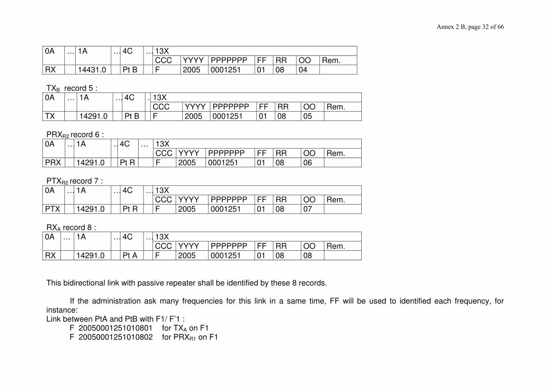
Annex 2 B, page 32 of 66
0A … 1A … 4C … 13X CCC YYYY PPPPPPP FF RR OO Rem.
RX 14431.0 Pt B F 2005 0001251 01 08 04 TXB record 5 : 0A … 1A … 4C …13X
CCC YYYY PPPPPPP FF RR OO Rem. TX 14291.0 Pt B F 2005 0001251 01 08 05 PRXR2 record 6 : 0A … 1A …4C … 13X
CCC YYYY PPPPPPP FF RR OO Rem. PRX 14291.0 Pt R F 2005 0001251 01 08 06 PTXR2 record 7 : 0A … 1A … 4C … 13X
CCC YYYY PPPPPPP FF RR OO Rem. PTX 14291.0 Pt R F 2005 0001251 01 08 07 RXA record 8 : 0A … 1A … 4C … 13X
CCC YYYY PPPPPPP FF RR OO Rem. RX 14291.0 Pt A F 2005 0001251 01 08 08 This bidirectional link with passive repeater shall be identified by these 8 records.
If the administration ask many frequencies for this link in a same time, FF will be used to identified each frequency, for instance: Link between PtA and PtB with F1/ F’1 : F 20050001251010801 for TXA on F1 F 20050001251010802 for PRXR1 on F1

Annex 2 B, page 33 of 66
F 20050001251010803 for PTXR1 on F1 F 20050001251010804 for RXB on F1 F 20050001251010805 for TXB on F’1 F 20050001251010806 for PRXR2 on F’1 F 20050001251010807 for PTXR2 on F’1 F 20050001251010808 for RXA on F’1 Link between PtA and PtB with F2/ F’2 : F 20050001251020801 for TXA on F2 F 20050001251020802 for PRXR1 on F2 F 20050001251020803 for PTXR1 on F2 F 20050001251020804 for RXB on F2 F 20050001251020805 for TXB on F’2 F 20050001251020806 for PRXR2 on F’2 F 20050001251020807 for PTXR2 on F’2 F 20050001251020808 for RXA on F’2 Link between PtA and PtB with F3/ F’3 : F 20050001251030801 for TXA on F3 F 20050001251030802 for PRXR1 on F3 F 20050001251030803 for PTXR1 on F3 F 20050001251030804 for RXB on F3 F 20050001251030805 for TXB on F’3 F 20050001251030806 for PRXR2 on F’3 F 20050001251030807 for PTXR2 on F’3 F 20050001251030808 for RXA on F’3

Annex 2 B, page 34 of 66
Appendix 4 to Annex 2 B FIELD 1Z : FREQUENCY CATEGORIES 1 Preferential frequencies 2 Frequencies requiring co-ordination 3 Frequencies used on the basis of geographical network plans 4 Frequencies for a planned radiocommunications network 5 Shared frequencies 6 not used 7 Frequencies using preferential codes 8 Frequencies used on the basis of arrangements between operators

Annex 2 B, page 35 of 66
Appendix 5 to Annex 2 B FIELD 6A : CLASS OF STATION FX Fixed station If other codes are required, use the codes listed in Appendix 5 of Section 9 of the Radiocommunication Data Dictionary

Annex 2 B, page 36 of 66
Appendix 6 to Annex 2 B FIELD 6B : NATURE OF THE SERVICE CO Station open to official correspondence exclusively CP Station open to public correspondence CR Station open to limited public correspondence CV Station open exclusively to correspondence of a private agency OT Station open exclusively to operational traffic of the service concerned If other codes are required, use the codes listed in Appendix 13 of Section 9 of the Radiocommunication Data Dictionary

Annex 2 B, page 37 of 66
Appendix 7 to Annex 2 B FIELD 6Z : CATEGORY OF USE A Airport services B Railways (excluding mountain railways) C Diplomatic corps D Mountain railways E Production, transport and distribution of energy (electricity, gas, water) F Fire services G Military H Radio relay networks HH Local call I Demonstration K Public transport L Subscriber installations, public mobile services, stand-by links M Navigation (in ports, on the Rhine, etc.) N Tests and research O Not allocated P Public security services (Police, customs, etc.) Q Entries not falling within other categories on this list (cordless microphones, etc.) R Ancillary broadcasting services (studio, news reporting) S Rescue services (ambulances, doctors, water and mountain rescue) T Other services provided by telecommunications administrations U lndustrial operators V Road traffic service W Taxi and car hire firms X Other private services Y Reserved specific applications, not allocated Z Other private multiple-use networks These codes can be combined (maximum two characters): e.g. XP- private police service

Annex 2 B, page 38 of 66
Appendix 8 to Annex 2 B FIELD 4A : ABBREVIATIONS NORMALLY USED WHEN THE NAME OF THE STATION
EXCEEDS 20 CHARACTERS AND CODES Abbreviations Explanation B Bay BRDG Bridge C Cape CL Central CP Camp CY City DPT Department E East ET State FT Fort FIR Fire Tower GF Gulf GR Great HLL Hill HR Harbour I Island(s) INTR Usage in the whole country JN Junction L Lake LSTN Light station MT Mount MTN Mountain(s) N New NO North NTL National PK Peak PMSTN Pump station PT Port (see HR) RV River S Saint STN Station SO South TR Tower V Town (see CY) VLY Valley W West If additional abbreviations are required, use those listed in Appendix 7 of Section 9 of the Radiocommunication Data Dictionary

Annex 2 B, page 39 of 66
Appendix 9 to Annex 2 B FIELD 13Y : STATUS OF CO-ORDINATION A For information : the assignment described is not submitted to a co-ordination
procedure and to any protection requirement. B Request for agreement. C Agreed without reservation. D Temporary status: Coordination subject to operational tests to show that
coexistence is possible. E Agreement on a non-interference basis (NIB); revocation of the agreement and any
request to cease the emissions in question requires proof that harmful interference has been caused to assignments whose status has already been established, which should normally be described in an associated notice.
F Agreed, subject to a requirement identical or analogous to the requirement
of RR 4.4. G Agreed, without any reservation as to interference which may be caused by the
assignment described; the applicant is, however, informed that there is a risk of interference from assignments whose status has already been established, and that the responsibility for any such risk is his; one or more associated notices may be sent.
H E+G P Assignment according to preferential frequency agreements (1.3.2 of the
Agreement) or geographical network plans (1.3.5 of the Agreement) or shared frequency agreements (1.3.3 of the Agreement) or frequencies using preferential codes (1.3.6 of the Agreement) or frequencies used on the basis of arrangements between operators (1.3.7 of the Agreement).
R Deletion of co-ordination. W Withdrawal of the co-ordination request. Y Request for agreement refused, but an alternative suggestion is formulated in
column 13Z. Z Request for agreement refused. Notes: Statuses B, C, E, G , Z are mostly used. For frequency bands used for national defence purposes status G 2.4 is applicable. Explanatory note for the status G: Agreed but protection from interference cannot be guaranteed to the receiver under request from assignments whose status has already been established and the applicant is informed that the responsibility for any such risk is his; one or more explanatory notices may be sent.

Annex 2 B, page 40 of 66
Appendix 10 to Annex 2 B FIELD 9D : POLARIZATION
SYMBOLS USED TO INDICATE POLARIZATION
Polarization Symbol Definition Horizontal linear
H
The electric field intensity vector is in the horizontal plane.
Vertical linear
V
The magnetic field intensity vector is in the horizontal plane.

Annex 2 B, page 41 of 66
Appendix 11 to Annex 2 B FIELD 7K: MAX. CAPACITY OF THE LINK
Contents of the field 7K
E1 2 Mbit/s 2E1 2 x 2 Mbit/s 4E1 4 x 2 Mbit/s 8E1 8 x 2 Mbit/s 16E1 16 x 2 Mbit/s 17E1 17 x 2 Mbit/s E2 8 Mbit/s 2E2 2 x 8 Mbit/s E3 34 Mbit/s 2E3 2 x 34 Mbit/s E3 + E1 34 + 2 Mbit/s E4 140 Mbit/s 2E4 2 x 140 Mbit/s STM1 155 Mbit/s 2STM1 2 x 155 Mbit/s X Unknown
Other capacities should be derived accordingly.

Annex 2 B, page 42 of 66
Appendix 12 to Annex 2 B
FIELD 7G: TABLE OF DEFAULT VALUES OF TRANSMITTER SPECTRUM MASKS AND RECEIVER SELECTIVITY MASKS
Frequency band, system and class TX MASKS
Band System
Equipment Class
Channel Separation
Netto-Bitrate
f1 (MHz)
a1 (dB)
f2 (MHz)
a2 (dB)
f3 (MHz)
a3 (dB)
f4 (MHz)
a4 (dB)
f5 (MHz)
a5 (dB)
f6 (MHz)
a6 (dB)
MHz Field 7G1
MHz (Mbit/s)
1350 - 1517 A1 2 0.025 0.032 0.01102 0.0 0.01224 2.0 0.01273 6.9 0.01322 16.1 0.01371 28.0 0.040 48.0
1350 - 1517 A1 2 0.075 0.096 0.03305 0.0 0.03672 2.0 0.03819 6.9 0.03966 16.1 0.04114 28.0 0.120 48.0
1350 - 1517 A1 2 0.250 0.325 0.06280 0.0 0.10644 2.0 0.12453 7.1 0.13837 13.6 0.15258 28.0 0.400 48.0
1350 - 1517 A1 2 0.500 0.650 0.12560 0.0 0.21288 2.0 0.24906 7.1 0.27674 13.6 0.30515 28.0 0.800 48.0
1350 - 1517 A1 2 1.000 1.3 0.25119 0.0 0.42575 2.0 0.49813 7.1 0.55348 13.6 0.61031 28.0 1.600 48.0
1350 - 1517 A1 2 2.000 2.6 0.50239 0.0 0.85150 2.0 0.99626 7.1 1.10695 13.6 1.22062 28.0 3.200 48.0
1350 - 1517 UM 2 3.500 4.0 1.03180 0.0 1.54000 2.0 1.72480 6.4 1.87880 11.7 2.08320 24.0 6.000 46.0
1350 - 1517 A1 4L 0.025 0.064 0.00708 0.0 0.01056 2.0 0.01214 7.6 0.01331 15.6 0.01429 33.0 0.040 56.0
1350 - 1517 A1 4L 0.075 0.190 0.02038 0.0 0.03135 2.0 0.03637 7.7 0.04013 16.1 0.04307 33.0 0.120 56.0
1350 - 1517 A1 4L 0.250 0.650 0.07508 0.0 0.10725 2.0 0.12227 7.8 0.13299 16.1 0.14193 33.0 0.400 56.0
1350 - 1517 A1 4L 0.500 1.3 0.15015 0.0 0.21450 2.0 0.24453 7.8 0.26598 16.1 0.28385 33.0 0.800 56.0
1350 - 1517 A1 4L 1.000 2.6 0.30030 0.0 0.42900 2.0 0.48906 7.8 0.53196 16.1 0.56770 33.0 1.600 56.0
1350 - 1517 A1 4L 2.000 5.2 0.60060 0.0 0.85800 2.0 0.97812 7.8 1.06392 16.1 1.13540 33.0 3.200 56.0
1350 - 1517 UM 4L 3.500 8.0 1.45960 0.0 1.64000 2.0 1.72200 7.6 1.77120 13.5 1.85540 29.0 7.000 56.0
2025 - 2670 A2 2 0.50 0.65 0.12560 0.0 0.21288 2.0 0.24906 7.1 0.27674 13.6 0.30515 28.0 0.800 48.0
2025 - 2670 A2 2 1.00 1.3 0.25119 0.0 0.42575 2.0 0.49813 7.1 0.55348 13.6 0.61031 28.0 1.600 48.0
2025 - 2670 A2 2 2.00 2.6 0.50239 0.0 0.85150 2.0 0.99626 7.1 1.10695 13.6 1.22062 28.0 3.200 48.0

Annex 2 B, page 43 of 66
Frequency band, system and class TX MASKS
Band System
Equipment Class
Channel Separation
Netto-Bitrate
f1 (MHz)
a1 (dB)
f2 (MHz)
a2 (dB)
f3 (MHz)
a3 (dB)
f4 (MHz)
a4 (dB)
f5 (MHz)
a5 (dB)
f6 (MHz)
a6 (dB)
MHz Field 7G1
MHz (Mbit/s)
2025 - 2670 UM 2 1.75 2.0 0.56880 0.0 0.79000 2.0 0.86900 6.3 0.94010 12.0 1.02870 24.0 3.000 46.0
2025 - 2670 UM 2 3.50 4.0 1.03180 0.0 1.54000 2.0 1.72480 6.4 1.87880 11.7 2.08320 24.0 6.000 46.0
2025 - 2670 UM 2 7.00 8.0 2.06360 0.0 3.08000 2.0 3.44960 6.4 3.75760 11.7 4.16640 24.0 12.000 46.0
2025 - 2670 UM 2 14.00 16.0 4.12720 0.0 6.16000 2.0 6.89920 6.4 7.51520 11.7 8.33280 24.0 24.000 46.0
2025 - 2670 A2 4L 0.50 1.3 0.15015 0.0 0.21450 2.0 0.24453 7.8 0.26598 16.1 0.28385 33.0 0.800 56.0
2025 - 2670 A2 4L 1.00 2.6 0.30030 0.0 0.42900 2.0 0.48906 7.8 0.53196 16.1 0.56770 33.0 1.600 56.0
2025 - 2670 A2 4L 2.00 5.2 0.60060 0.0 0.85800 2.0 0.97812 7.8 1.06392 16.1 1.13540 33.0 3.200 56.0
2025 - 2670 UM 4L 1.75 4.0 0.72980 0.0 0.82000 2.0 0.86100 7.6 0.88560 13.5 0.92770 29.0 3.500 56.0
2025 - 2670 UM 4L 3.50 8.0 1.45960 0.0 1.64000 2.0 1.72200 7.6 1.77120 13.5 1.85540 29.0 7.000 56.0
2025 - 2670 UM 4L 7.00 16.0 2.91920 0.0 3.28000 2.0 3.44400 7.6 3.54240 13.5 3.71080 29.0 14.000 56.0
2025 - 2670 UM 4L 14.00 34.0 5.82505 0.0 6.54500 2.0 6.87225 7.6 7.06860 13.5 7.40495 29.0 28.000 56.0
3410 - 11700 UM 2 1.75 2 0.56880 0.0 0.79000 2.0 0.86900 6.3 0.94010 12.0 1.02870 24.0 3.000 46.0
3410 - 11700 UM 2 3.5 4 1.03180 0.0 1.54000 2.0 1.72480 6.4 1.87880 11.7 2.08320 24.0 6.000 46.0
3410 - 11700 UM 2 7.0 … 11.7 8 2.06360 0.0 3.08000 2.0 3.44960 6.4 3.75760 11.7 4.16640 24.0 12.000 46.0
3410 - 11700 UM 2 14.0 … 15.0 16 4.12720 0.0 6.16000 2.0 6.89920 6.4 7.51520 11.7 8.33280 24.0 24.000 46.0
3410 - 11700 UM 2 28.0 … 30.0 34 9.24545 0.0 12.66500 2.0 13.93150 6.5 15.07135 12.7 16.36455 25.0 45.000 47.0
3410 - 11700 UM 4L 1.75 4 0.72980 0.0 0.82000 2.0 0.86100 7.6 0.88560 13.5 0.92770 29.0 3.500 56.0
3410 - 11700 UM 4L 3.5 8 1.45960 0.0 1.64000 2.0 1.72200 7.6 1.77120 13.5 1.85540 29.0 7.000 56.0
3410 - 11700 UM 4L 7.0 … 11.7 16 2.91920 0.0 3.28000 2.0 3.44400 7.6 3.54240 13.5 3.71080 29.0 14.000 56.0
3410 - 11700 UM 4L 14.0 … 15.0 34 5.82505 0.0 6.54500 2.0 6.87225 7.6 7.06860 13.5 7.40495 29.0 28.000 56.0
3410 - 11700 UM 4L 28.0 … 30.0 68 11.51920 0.0 13.09000 2.0 13.74450 7.1 14.26810 14.2 14.94080 29.0 56.000 57.0
3410 - 11700 B1 4L 20.0 51 3.38576 0.0 7.20375 2.0 9.07673 8.2 10.30136 16.6 11.22174 37.0 30.000 56.0
3410 - 11700 UM 4H 14.0 … 15.0 51 5.48250 0.0 6.37500 2.0 6.82125 8.3 7.07625 15.5 7.40750 34.0 27.500 56.0
3410 - 11700 UM 4H 28.0 … 30.0 102 10.96500 0.0 12.75000 2.0 13.64250 8.3 14.28000 19.0 14.81500 35.0 55.000 57.0

Annex 2 B, page 44 of 66
Frequency band, system and class TX MASKS
Band System
Equipment Class
Channel Separation
Netto-Bitrate
f1 (MHz)
a1 (dB)
f2 (MHz)
a2 (dB)
f3 (MHz)
a3 (dB)
f4 (MHz)
a4 (dB)
f5 (MHz)
a5 (dB)
f6 (MHz)
a6 (dB)
MHz Field 7G1
MHz (Mbit/s)
3410 - 11700 UM 4H 56.0 … 60.0 204 21.93000 0.0 25.50000 2.0 27.28500 8.3 28.56000 19.0 29.63000 35.0 110.000 57.0
3410 - 11700 UM 5A 28.0 … 30.0 155 11.36593 0.0 13.06429 2.0 13.97879 9.0 14.50136 18.4 15.04264 37.0 54.000 57.0
3410 - 11700 UM 5A 56.0 … 60.0 310 22.73186 0.0 26.12857 2.0 27.95757 9.0 29.00271 18.4 30.08529 37.0 108.000 57.0
3410 - 11700 UM 5B 7.0 34 2.58683 0.0 3.11667 2.0 3.39717 8.8 3.55300 17.2 3.71650 37.0 13.500 56.0
3410 - 11700 UM 5B 14.0 … 15.0 68 5.17367 0.0 6.23333 2.0 6.79433 8.8 7.10600 17.2 7.43300 37.0 27.000 56.0
3410 - 11700 UM 5B 28.0 … 30.0 155 10.60200 0.0 12.62143 2.0 13.63114 8.3 14.38843 20.2 14.92086 38.0 54.000 57.0
3410 - 11700 C1 5B 40.0 155 9.14500 0.0 15.50000 2.0 18.60000 8.1 20.61500 16.3 22.25500 36.0 67.000 56.0
3410 - 11700 UM 5B 56.0 … 60.0 310 21.20400 0.0 25.24286 2.0 27.26229 8.3 28.77686 20.2 29.84171 38.0 108.000 57.0
3410 - 11700 UM 6A 28.0 … 30.0 204 11.05425 0.0 13.00500 2.0 14.04540 8.9 14.69565 19.6 15.23575 37.0 54.000 57.0
3410 - 11700 C2 6A 40.0 310 18.19894 0.0 19.56875 2.0 20.35150 9.6 20.74288 19.0 21.33856 33.0 38.400 56.0
3410 - 11700 UM 6A 56.0 … 60.0 408 21.84840 0.0 26.01000 2.0 28.09080 8.3 29.39130 16.7 30.73160 37.0 108.000 57.0
3410 - 11700 UM 6B 7.0 51 2.74125 0.0 3.18750 2.0 3.41063 8.3 3.57000 19.0 3.70375 37.0 13.500 56.0
3410 - 11700 UM 6B 14.0 … 15.0 102 5.48250 0.0 6.37500 2.0 6.82125 8.3 7.14000 19.0 7.40750 37.0 27.000 56.0
3410 - 11700 UM 6B 28.0 … 30.0 204 10.96500 0.0 12.75000 2.0 13.64250 8.3 14.28000 19.0 14.81500 38.0 54.000 57.0
3410 - 11700 C3 6B 40.0 310 18.40625 0.0 19.37500 2.0 19.95625 10.2 20.34375 41.0 20.74375 41.0 29.800 56.0
3410 - 11700 UM 6B 56.0 … 60.0 408 21.93000 0.0 25.50000 2.0 27.28500 8.3 28.56000 19.0 29.63000 38.0 108.000 57.0
12750 - 15350 UM 2 1.75 2 0.51590 0.0 0.77000 2.0 0.86240 6.4 0.93940 11.7 1.04160 24.0 3.000 46.0
12750 - 15350 UM 2 3.5 4 1.03180 0.0 1.54000 2.0 1.72480 6.4 1.87880 11.7 2.08320 24.0 6.000 46.0
12750 - 15350 UM 2 7.0 8 2.06360 0.0 3.08000 2.0 3.44960 6.4 3.75760 11.7 4.16640 24.0 12.000 46.0
12750 - 15350 UM 2 14.0 16 4.12720 0.0 6.16000 2.0 6.89920 6.4 7.51520 11.7 8.33280 24.0 24.000 46.0
12750 - 15350 UM 2 28.0 34 9.24545 0.0 12.66500 2.0 13.93150 6.5 15.07135 12.7 16.36455 25.0 45.000 47.0
12750 - 15350 UM 2 56.0 68 19.89680 0.0 25.84000 2.0 28.16560 6.7 29.97440 12.5 32.34320 25.0 90.000 47.0
12750 - 15350 UM 4L 1.75 4 0.70090 0.0 0.81500 2.0 0.86390 7.3 0.90465 15.5 0.94660 29.0 3.500 56.0
12750 - 15350 UM 4L 3.5 8 1.42680 0.0 1.64000 2.0 1.73840 7.7 1.80400 14.9 1.88820 29.0 7.000 56.0

Annex 2 B, page 45 of 66
Frequency band, system and class TX MASKS
Band System
Equipment Class
Channel Separation
Netto-Bitrate
f1 (MHz)
a1 (dB)
f2 (MHz)
a2 (dB)
f3 (MHz)
a3 (dB)
f4 (MHz)
a4 (dB)
f5 (MHz)
a5 (dB)
f6 (MHz)
a6 (dB)
MHz Field 7G1
MHz (Mbit/s)
12750 - 15350 UM 4L 7.0 16 2.85360 0.0 3.28000 2.0 3.47680 7.7 3.60800 14.9 3.77640 29.0 14.000 56.0
12750 - 15350 UM 4L 14.0 34 5.69415 0.0 6.54500 2.0 6.93770 7.7 7.19950 14.9 7.53585 29.0 28.000 56.0
12750 - 15350 UM 4L 28.0 68 11.38830 0.0 13.09000 2.0 13.87540 7.7 14.39900 14.9 15.07170 29.0 56.000 57.0
12750 - 15350 UM 4L 56.0 155 22.41881 0.0 25.76875 2.0 27.31488 7.7 28.34563 14.9 29.67869 29.0 112.000 57.0
12750 - 15350 UM 4H 14.0 51 5.41875 0.0 6.37500 2.0 6.82125 7.8 7.14000 16.1 7.47125 34.0 27.500 56.0
12750 - 15350 UM 4H 28.0 102 10.71000 0.0 12.75000 2.0 13.77000 8.3 14.40750 16.7 15.07000 35.0 55.000 57.0
12750 - 15350 UM 4H 56.0 204 21.42000 0.0 25.50000 2.0 27.54000 8.3 28.81500 16.7 30.14000 35.0 110.000 57.0
12750 - 15350 UM 5A 28.0 155 11.36593 0.0 13.06429 2.0 13.97879 9.0 14.50136 18.4 15.04264 37.0 54.000 57.0
12750 - 15350 UM 5A 56.0 310 22.73186 0.0 26.12857 2.0 27.95757 9.0 29.00271 18.4 30.08529 37.0 108.000 57.0
12750 - 15350 UM 5B 7.0 34 2.61800 0.0 3.11667 2.0 3.36600 8.3 3.52183 16.7 3.68533 37.0 13.500 56.0
12750 - 15350 UM 5B 14.0 68 5.23600 0.0 6.23333 2.0 6.73200 8.3 7.04367 16.7 7.37067 37.0 27.000 56.0
12750 - 15350 UM 5B 28.0 155 10.60200 0.0 12.62143 2.0 13.63114 8.3 14.38843 20.2 14.92086 38.0 54.000 57.0
12750 - 15350 UM 5B 56.0 310 21.45643 0.0 25.24286 2.0 27.26229 8.9 28.52443 19.6 29.58929 38.0 108.000 57.0
12750 - 15350 UM 6A 28.0 204 11.05425 0.0 13.00500 2.0 14.04540 8.9 14.69565 19.6 15.23575 37.0 54.000 57.0
12750 - 15350 UM 6A 56.0 408 22.10850 0.0 26.01000 2.0 28.09080 8.9 29.39130 19.6 30.47150 37.0 108.000 57.0
12750 - 15350 UM 6B 7.0 51 2.74125 0.0 3.18750 2.0 3.41063 8.3 3.57000 19.0 3.70375 37.0 13.500 56.0
12750 - 15350 UM 6B 14.0 102 5.48250 0.0 6.37500 2.0 6.82125 8.3 7.14000 19.0 7.40750 37.0 27.000 56.0
12750 - 15350 UM 6B 28.0 204 10.96500 0.0 12.75000 2.0 13.64250 8.3 14.28000 19.0 14.81500 38.0 54.000 57.0
12750 - 15350 UM 6B 56.0 408 21.93000 0.0 25.50000 2.0 27.28500 8.3 28.56000 19.0 29.63000 38.0 108.000 57.0
17700 - 19700 UM 2 1.75 2 0.47565 0.0 0.75500 2.0 0.85315 6.2 0.94375 12.0 1.05185 24.0 3.000 46.0
17700 - 19700 UM 2 3.5 4 0.95130 0.0 1.51000 2.0 1.70630 6.2 1.88750 12.0 2.10370 24.0 6.000 46.0
17700 - 19700 UM 2 7.0 8 1.90260 0.0 3.02000 2.0 3.41260 6.2 3.77500 12.0 4.20740 24.0 12.000 46.0
17700 - 19700 UM 2 13.75 … 14.0 16 3.80520 0.0 6.04000 2.0 6.82520 6.2 7.55000 12.0 8.41480 24.0 24.000 46.0
17700 - 19700 UM 2 27.5 … 28.0 34 9.24545 0.0 12.66500 2.0 13.93150 6.5 15.07135 12.7 16.36455 25.0 45.000 47.0

Annex 2 B, page 46 of 66
Frequency band, system and class TX MASKS
Band System
Equipment Class
Channel Separation
Netto-Bitrate
f1 (MHz)
a1 (dB)
f2 (MHz)
a2 (dB)
f3 (MHz)
a3 (dB)
f4 (MHz)
a4 (dB)
f5 (MHz)
a5 (dB)
f6 (MHz)
a6 (dB)
MHz Field 7G1
MHz (Mbit/s)
17700 - 19700 UM 2 55.0 … 56.0 68 19.89680 0.0 25.84000 2.0 28.16560 6.7 29.97440 12.5 32.34320 25.0 90.000 47.0
17700 - 19700 UM 4L 1.75 4 0.70090 0.0 0.81500 2.0 0.86390 7.3 0.90465 15.5 0.94660 29.0 3.100 51.0
17700 - 19700 UM 4L 3.5 8 1.40180 0.0 1.63000 2.0 1.72780 7.3 1.80930 15.5 1.89320 29.0 6.200 51.0
17700 - 19700 UM 4L 7.0 16 2.80360 0.0 3.26000 2.0 3.45560 7.3 3.61860 15.5 3.78640 29.0 12.400 51.0
17700 - 19700 UM 4L 13.75 … 14.0 34 5.69415 0.0 6.54500 2.0 6.93770 7.7 7.19950 14.9 7.53585 29.0 24.800 51.0
17700 - 19700 UM 4L 27.5 … 28.0 68 11.38830 0.0 13.09000 2.0 13.87540 7.7 14.39900 14.9 15.07170 29.0 49.000 52.0
17700 - 19700 UM 4L 55.0 … 56.0 155 22.41881 0.0 25.76875 2.0 27.31488 7.7 28.34563 14.9 29.67869 29.0 98.000 52.0
17700 - 19700 UM 4H 13.75 … 14.0 51 5.41875 0.0 6.37500 2.0 6.82125 7.8 7.14000 16.1 7.47125 34.0 24.150 51.0
17700 - 19700 UM 4H 27.5 … 28.0 102 10.71000 0.0 12.75000 2.0 13.77000 8.3 14.40750 16.7 15.07000 35.0 48.300 52.0
17700 - 19700 UM 4H 55.0 … 56.0 204 21.42000 0.0 25.50000 2.0 27.54000 8.3 28.81500 16.7 30.14000 35.0 96.600 52.0
17700 - 19700 UM 5A 27.5 … 28.0 155 11.36593 0.0 13.06429 2.0 13.97879 9.0 14.50136 18.4 15.04264 37.0 47.000 52.0
17700 - 19700 UM 5A 55.0 … 56.0 310 22.73186 0.0 26.12857 2.0 27.95757 9.0 29.00271 18.4 30.08529 37.0 94.000 52.0
17700 - 19700 UM 5B 7.0 34 2.61800 0.0 3.11667 2.0 3.36600 8.3 3.52183 16.7 3.68533 37.0 11.750 51.0
17700 - 19700 UM 5B 13.75 … 14.0 68 5.23600 0.0 6.23333 2.0 6.73200 8.3 7.04367 16.7 7.37067 37.0 23.500 51.0
17700 - 19700 UM 5B 27.5 … 28.0 155 10.60200 0.0 12.62143 2.0 13.63114 8.3 14.38843 20.2 14.92086 38.0 47.000 52.0
17700 - 19700 UM 5B 55.0 … 56.0 310 21.45643 0.0 25.24286 2.0 27.26229 8.9 28.52443 19.6 29.58929 38.0 94.000 52.0
17700 - 19700 UM 6A 27.5 … 28.0 204 10.92420 0.0 13.00500 2.0 14.04540 8.3 14.69565 16.7 15.36580 37.0 47.000 52.0
17700 - 19700 UM 6A 55.0 … 56.0 408 22.10850 0.0 26.01000 2.0 28.09080 8.9 29.39130 19.6 30.47150 37.0 94.000 52.0
17700 - 19700 UM 6B 7.0 51 2.77313 0.0 3.18750 2.0 3.41063 9.0 3.53813 18.4 3.67188 37.0 11.750 51.0
17700 - 19700 UM 6B 13.75 … 14.0 102 5.54625 0.0 6.37500 2.0 6.82125 9.0 7.07625 18.4 7.34375 37.0 23.500 51.0
17700 - 19700 UM 6B 27.5 … 28.0 204 10.96500 0.0 12.75000 2.0 13.64250 8.3 14.28000 19.0 14.81500 38.0 47.000 52.0
17700 - 19700 UM 6B 55.0 … 56.0 408 21.93000 0.0 25.50000 2.0 27.28500 8.3 28.56000 19.0 29.63000 38.0 94.000 52.0
22000 - 29500 UM 2 1.75 2 0.47565 0.0 0.75500 2.0 0.85315 6.2 0.94375 12.0 1.05185 24.0 3.000 46.0
22000 - 29500 UM 2 3.5 4 0.95130 0.0 1.51000 2.0 1.70630 6.2 1.88750 12.0 2.10370 24.0 6.000 46.0

Annex 2 B, page 47 of 66
Frequency band, system and class TX MASKS
Band System
Equipment Class
Channel Separation
Netto-Bitrate
f1 (MHz)
a1 (dB)
f2 (MHz)
a2 (dB)
f3 (MHz)
a3 (dB)
f4 (MHz)
a4 (dB)
f5 (MHz)
a5 (dB)
f6 (MHz)
a6 (dB)
MHz Field 7G1
MHz (Mbit/s)
22000 - 29500 UM 2 7.0 8 1.90260 0.0 3.02000 2.0 3.41260 6.2 3.77500 12.0 4.20740 24.0 12.000 46.0
22000 - 29500 UM 2 14.0 16 3.80520 0.0 6.04000 2.0 6.82520 6.2 7.55000 12.0 8.41480 24.0 24.000 46.0
22000 - 29500 UM 2 28.0 34 9.24545 0.0 12.66500 2.0 13.93150 6.5 15.07135 12.7 16.36455 25.0 45.000 47.0
22000 - 29500 UM 2 56.0 68 19.89680 0.0 25.84000 2.0 28.16560 6.7 29.97440 12.5 32.34320 25.0 90.000 47.0
22000 - 29500 UM 4L 1.75 4 0.70090 0.0 0.81500 2.0 0.86390 7.3 0.90465 15.5 0.94660 29.0 3.100 51.0
22000 - 29500 UM 4L 3.5 8 1.40180 0.0 1.63000 2.0 1.72780 7.3 1.80930 15.5 1.89320 29.0 6.200 51.0
22000 - 29500 UM 4L 7.0 16 2.80360 0.0 3.26000 2.0 3.45560 7.3 3.61860 15.5 3.78640 29.0 12.400 51.0
22000 - 29500 UM 4L 14.0 34 5.69415 0.0 6.54500 2.0 6.93770 7.7 7.19950 14.9 7.53585 29.0 24.800 51.0
22000 - 29500 UM 4L 28.0 68 11.38830 0.0 13.09000 2.0 13.87540 7.7 14.39900 14.9 15.07170 29.0 49.000 52.0
22000 - 29500 UM 4L 56.0 155 22.75594 0.0 26.15625 2.0 27.72563 7.7 28.77188 14.9 30.11656 29.0 98.000 52.0
22000 - 29500 UM 4H 14.0 51 5.41875 0.0 6.37500 2.0 6.82125 7.8 7.14000 16.1 7.47125 34.0 24.150 51.0
22000 - 29500 UM 4H 28.0 102 10.71000 0.0 12.75000 2.0 13.77000 8.3 14.40750 16.7 15.07000 35.0 48.300 52.0
22000 - 29500 UM 4H 56.0 204 21.42000 0.0 25.50000 2.0 27.54000 8.3 28.81500 16.7 30.14000 35.0 96.600 52.0
22000 - 29500 UM 5A 28.0 155 11.36593 0.0 13.06429 2.0 13.97879 9.0 14.50136 18.4 15.04264 37.0 47.000 52.0
22000 - 29500 UM 5A 56.0 310 22.28014 0.0 25.90714 2.0 27.72064 8.3 29.016 19.0 30.09414 37.0 94.000 52.0
22000 - 29500 UM 5B 7.0 34 2.618 0.0 3.11667 2.0 3.366 8.3 3.52183 16.7 3.68533 37.0 11.750 51.0
22000 - 29500 UM 5B 14.0 68 5.236 0.0 6.23333 2.0 6.732 8.3 7.04367 16.7 7.37067 37.0 23.500 51.0
22000 - 29500 UM 5B 28.0 155 10.22336 0.0 12.62143 2.0 13.88357 8.8 14.64086 18.2 15.2995 37.0 47.000 52.0
22000 - 29500 UM 5B 56.0 310 21.45643 0.0 25.24286 2.0 27.26229 8.9 28.52443 19.6 29.58929 38.0 94.000 52.0
22000 - 29500 UM 6A 28.0 204 10.92420 0.0 13.00500 2.0 14.04540 8.3 14.69565 16.7 15.36580 37.0 47.000 52.0
22000 - 29500 UM 6A 56.0 408 21.84840 0.0 26.01000 2.0 28.09080 8.3 29.39130 16.7 30.73160 37.0 94.000 52.0
22000 - 29500 UM 6B 7.0 51 2.77313 0.0 3.18750 2.0 3.41063 9.0 3.53813 18.4 3.67188 37.0 11.750 51.0
22000 - 29500 UM 6B 14.0 102 5.54625 0.0 6.37500 2.0 6.82125 9.0 7.07625 18.4 7.34375 37.0 23.500 51.0
22000 - 29500 UM 6B 28.0 204 10.96500 0.0 12.75000 2.0 13.64250 8.3 14.28000 19.0 14.81500 38.0 47.000 52.0
22000 - 29500 UM 6B 56.0 408 21.93000 0.0 25.50000 2.0 27.28500 8.3 28.56000 19.0 29.63000 38.0 94.000 52.0

Annex 2 B, page 48 of 66
Frequency band, system and class TX MASKS
Band System
Equipment Class
Channel Separation
Netto-Bitrate
f1 (MHz)
a1 (dB)
f2 (MHz)
a2 (dB)
f3 (MHz)
a3 (dB)
f4 (MHz)
a4 (dB)
f5 (MHz)
a5 (dB)
f6 (MHz)
a6 (dB)
MHz Field 7G1
MHz (Mbit/s)
31000 - 57000 UM 2 1.75 2 0.47565 0.0 0.75500 2.0 0.85315 6.2 0.94375 12.0 1.05185 24.0 3.000 46.0
31000 - 57000 UM 2 3.5 4 0.95130 0.0 1.51000 2.0 1.70630 6.2 1.88750 12.0 2.10370 24.0 6.000 46.0
31000 - 57000 UM 2 7.0 8 1.90260 0.0 3.02000 2.0 3.41260 6.2 3.77500 12.0 4.20740 24.0 12.000 46.0
31000 - 57000 UM 2 14.0 16 3.80520 0.0 6.04000 2.0 6.82520 6.2 7.55000 12.0 8.41480 24.0 24.000 46.0
31000 - 57000 UM 2 28.0 34 9.11880 0.0 12.66500 2.0 13.93150 6.3 15.07135 12.0 16.49120 25.0 45.000 47.0
31000 - 57000 UM 2 56.0 68 19.89680 0.0 25.84000 2.0 28.16560 6.7 29.97440 12.5 32.34320 25.0 90.000 47.0
31000 - 57000 UM 4L 1.75 4 0.70090 0.0 0.81500 2.0 0.86390 7.3 0.90465 15.5 0.94660 29.0 2.600 46.0
31000 - 57000 UM 4L 3.5 8 1.41810 0.0 1.63000 2.0 1.72780 7.7 1.79300 14.9 1.87690 29.0 6.200 46.0
31000 - 57000 UM 4L 7.0 16 2.80360 0.0 3.26000 2.0 3.45560 7.3 3.61860 15.5 3.78640 29.0 10.400 46.0
31000 - 57000 UM 4L 14.0 34 5.69415 0.0 6.54500 2.0 6.93770 7.7 7.19950 14.9 7.53585 29.0 20.800 46.0
31000 - 57000 UM 4L 28.0 68 11.38830 0.0 13.09000 2.0 13.87540 7.7 14.39900 14.9 15.07170 29.0 49.000 52.0
31000 - 57000 UM 4L 56.0 155 22.75594 0.0 26.15625 2.0 27.72563 7.7 28.77188 14.9 30.11656 29.0 84.000 47.0
31000 - 57000 UM 4H 14.0 51 5.41875 0.0 6.37500 2.0 6.82125 7.8 7.14000 16.1 7.47125 34.0 20.850 46.0
31000 - 57000 UM 4H 28.0 102 10.83750 0.0 12.75000 2.0 13.64250 7.8 14.28000 16.1 14.94250 35.0 41.700 47.0
31000 - 57000 UM 4H 56.0 204 21.67500 0.0 25.50000 2.0 27.28500 7.8 28.56000 16.1 29.88500 35.0 83.400 47.0
31000 - 57000 UM 5A 28.0 155 11.36593 0.0 13.06429 2.0 13.97879 9.0 14.50136 18.4 15.04264 37.0 40.000 47.0
31000 - 57000 UM 5A 56.0 310 22.28014 0.0 25.90714 2.0 27.72064 8.3 29.01600 19.0 30.09414 37.0 80.000 47.0
31000 - 57000 UM 5B 7.0 34 2.61800 0.0 3.11667 2.0 3.36600 8.3 3.52183 16.7 3.68533 37.0 10.000 46.0
31000 - 57000 UM 5B 14.0 68 5.29833 0.0 6.23333 2.0 6.73200 8.9 7.04367 19.6 7.30833 37.0 20.000 46.0
31000 - 57000 UM 5B 28.0 155 10.72821 0.0 12.62143 2.0 13.63114 8.9 14.26221 19.6 14.79464 38.0 40.000 47.0
31000 - 57000 UM 5B 56.0 310 21.01800 0.0 25.02143 2.0 27.02314 8.3 28.52443 20.2 29.58486 38.0 80.000 47.0
31000 - 57000 UM 6A 28.0 204 11.05425 0.0 13.00500 2.0 14.04540 8.9 14.69565 19.6 15.23575 37.0 40.000 47.0
31000 - 57000 UM 6A 56.0 408 22.10850 0.0 26.01000 2.0 28.09080 8.9 29.39130 19.6 30.47150 37.0 80.000 47.0
31000 - 57000 UM 6B 7.0 51 2.80500 0.0 3.18750 2.0 3.37875 8.3 3.50625 17.7 3.64000 37.0 10.000 46.0

Annex 2 B, page 49 of 66
Frequency band, system and class TX MASKS
Band System
Equipment Class
Channel Separation
Netto-Bitrate
f1 (MHz)
a1 (dB)
f2 (MHz)
a2 (dB)
f3 (MHz)
a3 (dB)
f4 (MHz)
a4 (dB)
f5 (MHz)
a5 (dB)
f6 (MHz)
a6 (dB)
MHz Field 7G1
MHz (Mbit/s)
31000 - 57000 UM 6B 14.0 102 5.54625 0.0 6.37500 2.0 6.82125 9.0 7.07625 18.4 7.34375 37.0 20.000 46.0
31000 - 57000 UM 6B 28.0 204 10.96500 0.0 12.75000 2.0 13.64250 8.3 14.28000 19.0 14.81500 38.0 40.000 47.0
31000 - 57000 UM 6B 56.0 408 21.93000 0.0 25.50000 2.0 27.28500 8.3 28.56000 19.0 29.63000 38.0 80.000 47.0

Annex 2 B, page 50 of 66
Frequency band, system and class RX MASKS
Band System
Equipment Class
Channel Separation
Netto-Bitrate
f1 (MHz)
a1 (dB)
f2 (MHz)
a2 (dB)
f3 (MHz)
a3 (dB)
f4 (MHz)
a4 (dB)
f5 (MHz)
a5 (dB)
f6 (MHz)
a6 (dB)
MHz Field 7G1
MHz (Mbit/s)
1350 - 1517 A1 2 0.025 0.032 0.01102 0.0 0.01224 2.0 0.01285 8.3 0.01322 15.1 0.01346 38.0 0.02357 54.0
1350 - 1517 A1 2 0.075 0.096 0.03305 0.0 0.03672 2.0 0.03856 8.3 0.03966 15.1 0.04039 38.0 0.07071 54.0
1350 - 1517 A1 2 0.250 0.325 0.06280 0.0 0.10644 2.0 0.12879 8.5 0.14050 14.3 0.15008 38.0 0.22571 54.0
1350 - 1517 A1 2 0.500 0.650 0.12560 0.0 0.21288 2.0 0.25758 8.5 0.28100 14.3 0.30015 38.0 0.43179 54.0
1350 - 1517 A1 2 1.000 1.3 0.25119 0.0 0.42575 2.0 0.51516 8.5 0.56199 14.3 0.60031 38.0 0.86357 54.0
1350 - 1517 A1 2 2.000 2.6 0.50239 0.0 0.85150 2.0 1.03032 8.5 1.12398 14.3 1.20062 38.0 1.72714 54.0
1350 - 1517 UM 2 3.500 4.0 1.03180 0.0 1.54000 2.0 1.78640 8.1 1.92500 13.5 2.04820 35.0 2.56667 52.0
1350 - 1517 A1 4L 0.025 0.064 0.00708 0.0 0.01056 2.0 0.01257 9.7 0.01352 17.5 0.01404 44.5 0.02327 62.0
1350 - 1517 A1 4L 0.075 0.190 0.02038 0.0 0.03135 2.0 0.03762 9.6 0.04076 18.0 0.04232 44.5 0.06982 62.0
1350 - 1517 A1 4L 0.250 0.650 0.07508 0.0 0.10725 2.0 0.12548 9.5 0.13406 16.7 0.13943 44.5 0.22273 62.0
1350 - 1517 A1 4L 0.500 1.3 0.15015 0.0 0.21450 2.0 0.25097 9.5 0.26813 16.7 0.27885 44.5 0.42606 62.0
1350 - 1517 A1 4L 1.000 2.6 0.30030 0.0 0.42900 2.0 0.50193 9.5 0.53625 16.7 0.55770 44.5 0.85212 62.0
1350 - 1517 A1 4L 2.000 5.2 0.60060 0.0 0.85800 2.0 1.00386 9.5 1.07250 16.7 1.11540 44.5 1.70424 62.0
1350 - 1517 UM 4L 3.500 8.0 1.45960 0.0 1.64000 2.0 1.73840 9.1 1.78760 15.9 1.82040 42.5 2.88276 62.0
2025 - 2670 A2 2 0.50 0.65 0.12560 0.0 0.21288 2.0 0.25758 8.5 0.28100 14.3 0.30015 38.0 0.43179 54.0
2025 - 2670 A2 2 1.00 1.3 0.25119 0.0 0.42575 2.0 0.51516 8.5 0.56199 14.3 0.60031 38.0 0.86357 54.0
2025 - 2670 A2 2 2.00 2.6 0.50239 0.0 0.85150 2.0 1.03032 8.5 1.12398 14.3 1.20062 38.0 1.72714 54.0
2025 - 2670 UM 2 1.75 2.0 0.56880 0.0 0.79000 2.0 0.90060 8.3 0.96380 14.5 1.01120 35.0 1.28333 52.0
2025 - 2670 UM 2 3.50 4.0 1.03180 0.0 1.54000 2.0 1.78640 8.1 1.92500 13.5 2.04820 35.0 2.56667 52.0
2025 - 2670 UM 2 7.00 8.0 2.06360 0.0 3.08000 2.0 3.57280 8.1 3.85000 13.5 4.09640 35.0 5.13333 52.0
2025 - 2670 UM 2 14.00 16.0 4.12720 0.0 6.16000 2.0 7.14560 8.1 7.70000 13.5 8.19280 35.0 10.26667 52.0
2025 - 2670 A2 4L 0.50 1.3 0.15015 0.0 0.21450 2.0 0.25097 9.5 0.26813 16.7 0.27885 44.5 0.42606 62.0
2025 - 2670 A2 4L 1.00 2.6 0.30030 0.0 0.42900 2.0 0.50193 9.5 0.53625 16.7 0.55770 44.5 0.85212 62.0
2025 - 2670 A2 4L 2.00 5.2 0.60060 0.0 0.85800 2.0 1.00386 9.5 1.07250 16.7 1.11540 44.5 1.70424 62.0

Annex 2 B, page 51 of 66
Frequency band, system and class RX MASKS
Band System
Equipment Class
Channel Separation
Netto-Bitrate
f1 (MHz)
a1 (dB)
f2 (MHz)
a2 (dB)
f3 (MHz)
a3 (dB)
f4 (MHz)
a4 (dB)
f5 (MHz)
a5 (dB)
f6 (MHz)
a6 (dB)
MHz Field 7G1
MHz (Mbit/s)
2025 - 2670 UM 4L 1.75 4.0 0.72980 0.0 0.82000 2.0 0.86920 9.1 0.89380 15.9 0.91020 42.5 1.44138 62.0
2025 - 2670 UM 4L 3.50 8.0 1.45960 0.0 1.64000 2.0 1.73840 9.1 1.78760 15.9 1.82040 42.5 2.88276 62.0
2025 - 2670 UM 4L 7.00 16.0 2.91920 0.0 3.28000 2.0 3.47680 9.1 3.57520 15.9 3.64080 42.5 5.76552 62.0
2025 - 2670 UM 4L 14.00 34.0 5.82505 0.0 6.54500 2.0 6.93770 9.1 7.13405 15.9 7.26495 42.5 11.53103 62.0
3410 - 11700 UM 2 1.75 2 0.56880 0.0 0.79000 2.0 0.90060 8.3 0.96380 14.5 1.01120 35.0 1.28333 52.0
3410 - 11700 UM 2 3.5 4 1.03180 0.0 1.54000 2.0 1.78640 8.1 1.92500 13.5 2.04820 35.0 2.56667 52.0
3410 - 11700 UM 2 7.0 … 11.7 8 2.06360 0.0 3.08000 2.0 3.57280 8.1 3.85000 13.5 4.09640 35.0 5.13333 52.0
3410 - 11700 UM 2 14.0 … 15.0 16 4.12720 0.0 6.16000 2.0 7.14560 8.1 7.70000 13.5 8.19280 35.0 10.26667 52.0
3410 - 11700 UM 2 28.0 … 30.0 34 9.24545 0.0 12.66500 2.0 14.31145 8.0 15.32465 14.2 16.08455 36.0 20.43200 53.0
3410 - 11700 UM 4L 1.75 4 0.72980 0.0 0.82000 2.0 0.86920 9.1 0.89380 15.9 0.91020 42.5 1.44138 62.0
3410 - 11700 UM 4L 3.5 8 1.45960 0.0 1.64000 2.0 1.73840 9.1 1.78760 15.9 1.82040 42.5 2.88276 62.0
3410 - 11700 UM 4L 7.0 … 11.7 16 2.91920 0.0 3.28000 2.0 3.47680 9.1 3.57520 15.9 3.64080 42.5 5.76552 62.0
3410 - 11700 UM 4L 14.0 … 15.0 34 5.82505 0.0 6.54500 2.0 6.93770 9.1 7.13405 15.9 7.26495 42.5 11.53103 62.0
3410 - 11700 UM 4L 28.0 … 30.0 68 11.51920 0.0 13.09000 2.0 14.00630 9.9 14.39900 16.7 14.66080 43.0 21.92414 63.0
3410 - 11700 B1 4L 20.0 51 3.38576 0.0 7.20375 2.0 9.36488 9.5 10.44544 17.5 11.02174 45.0 18.77273 62.0
3410 - 11700 UM 4H 14.0 … 15.0 51 5.48250 0.0 6.37500 2.0 6.88500 9.6 7.14000 18.0 7.26750 45.0 14.45455 62.0
3410 - 11700 UM 4H 28.0 … 30.0 102 10.96500 0.0 12.75000 2.0 13.77000 9.6 14.28000 18.0 14.53500 46.0 27.75000 63.0
3410 - 11700 UM 4H 56.0 … 60.0 204 21.93000 0.0 25.50000 2.0 27.54000 9.6 28.56000 18.0 29.07000 46.0 55.50000 63.0
3410 - 11700 UM 5A 28.0 … 30.0 155 11.36593 0.0 13.06429 2.0 14.10943 10.5 14.63200 23.4 14.76264 47.0 26.45833 67.0
3410 - 11700 UM 5A 56.0 60.0 310 22.73186 0.0 26.12857 2.0 28.21886 10.5 29.26400 23.4 29.52529 47.0 52.91667 67.0
3410 - 11700 UM 5B 7.0 34 2.58683 0.0 3.11667 2.0 3.42833 10.0 3.58417 19.7 3.64650 46.5 6.52273 62.0
3410 - 11700 UM 5B 14.0 … 15.0 68 5.17367 0.0 6.23333 2.0 6.85667 10.0 7.16833 19.7 7.29300 46.5 13.04545 62.0
3410 - 11700 UM 5B 28.0 … 30.0 155 10.60200 0.0 12.62143 2.0 13.88357 10.7 14.38843 19.2 14.64086 47.5 25.54167 65.0
3410 - 11700 C1 5B 40.0 155 9.14500 0.0 15.50000 2.0 19.22000 9.9 20.92500 17.8 21.85500 46.0 31.31818 63.0
3410 - 11700 UM 5B 56.0 … 60.0 310 21.20400 0.0 25.24286 2.0 27.76714 10.7 28.77686 19.2 29.28171 47.5 51.08333 65.0

Annex 2 B, page 52 of 66
Frequency band, system and class RX MASKS
Band System
Equipment Class
Channel Separation
Netto-Bitrate
f1 (MHz)
a1 (dB)
f2 (MHz)
a2 (dB)
f3 (MHz)
a3 (dB)
f4 (MHz)
a4 (dB)
f5 (MHz)
a5 (dB)
f6 (MHz)
a6 (dB)
MHz Field 7G1
MHz (Mbit/s)
3410 - 11700 UM 6A 28.0 … 30.0 204 11.05425 0.0 13.00500 2.0 14.17545 10.2 14.69565 18.6 14.95575 47.0 27.29167 71.0
3410 - 11700 C2 6A 40.0 310 18.19894 0.0 19.56875 2.0 20.35150 9.6 20.74288 18.0 20.93856 44.5 31.66667 73.0
3410 - 11700 UM 6A 56.0 … 60.0 408 21.84840 0.0 26.01000 2.0 28.61100 10.7 29.65140 19.2 30.17160 47.0 54.58333 71.0
3410 - 11700 UM 6B 7.0 51 2.74125 0.0 3.18750 2.0 3.44250 9.6 3.57000 18.0 3.63375 46.5 6.52273 62.0
3410 - 11700 UM 6B 14.0 … 15.0 102 5.48250 0.0 6.37500 2.0 6.88500 9.6 7.14000 18.0 7.26750 46.5 13.04545 62.0
3410 - 11700 UM 6B 28.0 … 30.0 204 10.96500 0.0 12.75000 2.0 13.89750 11.2 14.28000 18.0 14.53500 47.5 26.58333 70.0
3410 - 11700 C3 6B 40.0 310 18.40625 0.0 19.37500 2.0 19.95625 10.2 20.34375 47.5 20.34385 48.5 24.41463 74.0
3410 - 11700 UM 6B 56.0 … 60.0 408 21.93000 0.0 25.50000 2.0 27.79500 11.2 28.56000 18.0 29.07000 47.5 53.16667 70.0
12750 - 15350 UM 2 1.75 2 0.51590 0.0 0.77000 2.0 0.89320 8.1 0.96250 13.5 1.02410 35.0 1.28333 52.0
12750 - 15350 UM 2 3.5 4 1.03180 0.0 1.54000 2.0 1.78640 8.1 1.92500 13.5 2.04820 35.0 2.56667 52.0
12750 - 15350 UM 2 7.0 8 2.06360 0.0 3.08000 2.0 3.57280 8.1 3.85000 13.5 4.09640 35.0 5.13333 52.0
12750 - 15350 UM 2 14.0 16 4.12720 0.0 6.16000 2.0 7.14560 8.1 7.70000 13.5 8.19280 35.0 10.26667 52.0
12750 - 15350 UM 2 28.0 34 9.24545 0.0 12.66500 2.0 14.31145 8.0 15.32465 14.2 16.08455 36.0 20.43200 53.0
12750 - 15350 UM 2 56.0 68 19.89680 0.0 25.84000 2.0 28.68240 8.0 30.49120 14.4 31.78320 36.0 40.86400 53.0
12750 - 15350 UM 4L 1.75 4 0.70090 0.0 0.81500 2.0 0.88020 9.6 0.91280 18.0 0.92910 42.5 1.44138 62.0
12750 - 15350 UM 4L 3.5 8 1.42680 0.0 1.64000 2.0 1.75480 9.0 1.82040 17.4 1.85320 42.5 2.88276 62.0
12750 - 15350 UM 4L 7.0 16 2.85360 0.0 3.28000 2.0 3.50960 9.0 3.64080 17.4 3.70640 42.5 5.76552 62.0
12750 - 15350 UM 4L 14.0 34 5.69415 0.0 6.54500 2.0 7.00315 9.0 7.26495 17.4 7.39585 42.5 11.53103 62.0
12750 - 15350 UM 4L 28.0 68 11.38830 0.0 13.09000 2.0 14.00630 9.0 14.52990 17.4 14.79170 43.0 21.92414 63.0
12750 - 15350 UM 4L 56.0 155 22.41881 0.0 25.76875 2.0 27.57256 9.0 28.60331 17.4 29.11869 43.0 43.84828 63.0
12750 - 15350 UM 4H 14.0 51 5.41875 0.0 6.37500 2.0 6.94875 10.2 7.20375 18.6 7.33125 45.0 14.45455 62.0
12750 - 15350 UM 4H 28.0 102 10.71000 0.0 12.75000 2.0 13.89750 9.5 14.53500 19.2 14.79000 46.0 27.75000 63.0
12750 - 15350 UM 4H 56.0 204 21.42000 0.0 25.50000 2.0 27.79500 9.5 29.07000 19.2 29.58000 46.0 55.50000 63.0
12750 - 15350 UM 5A 28.0 155 11.36593 0.0 13.06429 2.0 14.10943 10.5 14.63200 23.4 14.76264 47.0 26.45833 67.0
12750 - 15350 UM 5A 56.0 310 22.73186 0.0 26.12857 2.0 28.21886 10.5 29.26400 23.4 29.52529 47.0 52.91667 67.0

Annex 2 B, page 53 of 66
Frequency band, system and class RX MASKS
Band System
Equipment Class
Channel Separation
Netto-Bitrate
f1 (MHz)
a1 (dB)
f2 (MHz)
a2 (dB)
f3 (MHz)
a3 (dB)
f4 (MHz)
a4 (dB)
f5 (MHz)
a5 (dB)
f6 (MHz)
a6 (dB)
MHz Field 7G1
MHz (Mbit/s)
12750 - 15350 UM 5B 7.0 34 2.61800 0.0 3.11667 2.0 3.42833 10.7 3.55300 19.2 3.61533 46.5 6.52273 62.0
12750 - 15350 UM 5B 14.0 68 5.23600 0.0 6.23333 2.0 6.85667 10.7 7.10600 19.2 7.23067 46.5 13.04545 62.0
12750 - 15350 UM 5B 28.0 155 10.60200 0.0 12.62143 2.0 13.88357 10.7 14.38843 19.2 14.64086 47.5 25.54167 65.0
12750 - 15350 UM 5B 56.0 310 21.45643 0.0 25.24286 2.0 27.51471 10.2 28.52443 18.6 29.02929 47.5 51.91667 67.0
12750 - 15350 UM 6A 28.0 204 11.05425 0.0 13.00500 2.0 14.17545 10.2 14.69565 18.6 14.95575 47.0 27.29167 71.0
12750 - 15350 UM 6A 56.0 408 22.10850 0.0 26.01000 2.0 28.35090 10.2 29.39130 18.6 29.91150 47.0 54.58333 71.0
12750 - 15350 UM 6B 7.0 51 2.74125 0.0 3.18750 2.0 3.44250 9.6 3.57000 18.0 3.63375 46.5 6.52273 62.0
12750 - 15350 UM 6B 14.0 102 5.48250 0.0 6.37500 2.0 6.88500 9.6 7.14000 18.0 7.26750 46.5 13.04545 62.0
12750 - 15350 UM 6B 28.0 204 10.96500 0.0 12.75000 2.0 13.89750 11.2 14.28000 18.0 14.53500 47.5 26.58333 70.0
12750 - 15350 UM 6B 56.0 408 21.93000 0.0 25.50000 2.0 27.79500 11.2 28.56000 18.0 29.07000 47.5 53.16667 70.0
17700 - 19700 UM 2 1.75 2 0.47565 0.0 0.75500 2.0 0.89090 8.1 0.96640 13.4 1.03435 35.0 1.28333 52.0
17700 - 19700 UM 2 3.5 4 0.95130 0.0 1.51000 2.0 1.78180 8.1 1.93280 13.4 2.06870 35.0 2.56667 52.0
17700 - 19700 UM 2 7.0 8 1.90260 0.0 3.02000 2.0 3.56360 8.1 3.86560 13.4 4.13740 35.0 5.13333 52.0
17700 - 19700 UM 2 13.75 … 14.0 16 3.80520 0.0 6.04000 2.0 7.12720 8.1 7.73120 13.4 8.27480 35.0 10.26667 52.0
17700 - 19700 UM 2 27.5 … 28.0 34 9.24545 0.0 12.66500 2.0 14.31145 8.0 15.32465 14.2 16.08455 36.0 20.43200 53.0
17700 - 19700 UM 2 55.0 … 56.0 68 19.89680 0.0 25.84000 2.0 28.68240 8.0 30.49120 14.4 31.78320 36.0 40.86400 53.0
17700 - 19700 UM 4L 1.75 4 0.70090 0.0 0.81500 2.0 0.88020 9.6 0.91280 18.0 0.92910 40.0 1.38966 57.0
17700 - 19700 UM 4L 3.5 8 1.40180 0.0 1.63000 2.0 1.76040 9.6 1.82560 18.0 1.85820 40.0 2.77931 57.0
17700 - 19700 UM 4L 7.0 16 2.80360 0.0 3.26000 2.0 3.52080 9.6 3.65120 18.0 3.71640 40.0 5.55862 57.0
17700 - 19700 UM 4L 13.75 … 14.0 34 5.69415 0.0 6.54500 2.0 7.00315 9.0 7.26495 17.4 7.39585 40.0 11.11724 57.0
17700 - 19700 UM 4L 27.5 … 28.0 68 11.38830 0.0 13.09000 2.0 14.00630 9.0 14.52990 17.4 14.79170 40.5 21.48966 60.0
17700 - 19700 UM 4L 55.0 … 56.0 155 22.41881 0.0 25.76875 2.0 27.57256 9.0 28.60331 17.4 29.11869 40.5 42.68966 59.0
17700 - 19700 UM 4H 13.75 … 14.0 51 5.41875 0.0 6.37500 2.0 6.94875 10.2 7.20375 18.6 7.33125 42.5 13.77273 57.0
17700 - 19700 UM 4H 27.5 … 28.0 102 10.71000 0.0 12.75000 2.0 13.89750 9.5 14.53500 19.2 14.79000 43.5 27.00000 60.0
17700 - 19700 UM 4H 55.0 … 56.0 204 21.42000 0.0 25.50000 2.0 27.79500 9.5 29.07000 19.2 29.58000 43.5 54.00000 60.0

Annex 2 B, page 54 of 66
Frequency band, system and class RX MASKS
Band System
Equipment Class
Channel Separation
Netto-Bitrate
f1 (MHz)
a1 (dB)
f2 (MHz)
a2 (dB)
f3 (MHz)
a3 (dB)
f4 (MHz)
a4 (dB)
f5 (MHz)
a5 (dB)
f6 (MHz)
a6 (dB)
MHz Field 7G1
MHz (Mbit/s)
17700 - 19700 UM 5A 27.5 … 28.0 155 11.36593 0.0 13.06429 2.0 14.10943 10.5 14.50136 17.4 14.76264 44.5 26.45833 67.0
17700 - 19700 UM 5A 55.0 … 56.0 310 22.73186 0.0 26.12857 2.0 28.21886 10.5 29.00271 17.4 29.52529 44.5 52.91667 67.0
17700 - 19700 UM 5B 7.0 34 2.61800 0.0 3.11667 2.0 3.39717 9.5 3.55300 19.2 3.61533 44.0 6.23864 57.0
17700 - 19700 UM 5B 13.75 … 14.0 68 5.23600 0.0 6.23333 2.0 6.79433 9.5 7.10600 19.2 7.23067 44.0 12.47727 57.0
17700 - 19700 UM 5B 27.5 … 28.0 155 10.60200 0.0 12.62143 2.0 13.75736 9.5 14.38843 19.2 14.64086 45.0 25.54167 65.0
17700 - 19700 UM 5B 55.0 … 56.0 310 21.45643 0.0 25.24286 2.0 27.51471 10.2 28.52443 18.6 29.02929 45.0 51.91667 67.0
17700 - 19700 UM 6A 27.5 … 28.0 204 10.92420 0.0 13.00500 2.0 14.17545 9.5 14.82570 19.2 15.08580 44.5 27.29167 71.0
17700 - 19700 UM 6A 55.0 … 56.0 408 22.10850 0.0 26.01000 2.0 28.35090 10.2 29.39130 18.6 29.91150 44.5 54.58333 71.0
17700 - 19700 UM 6B 7.0 51 2.77313 0.0 3.18750 2.0 3.44250 10.5 3.53813 17.4 3.60188 44.0 6.40909 60.0
17700 - 19700 UM 6B 13.75 … 14.0 102 5.54625 0.0 6.37500 2.0 6.88500 10.5 7.07625 17.4 7.20375 44.0 12.81818 60.0
17700 - 19700 UM 6B 27.5 … 28.0 204 10.96500 0.0 12.75000 2.0 13.77000 9.6 14.28000 18.0 14.53500 45.0 26.58333 70.0
17700 - 19700 UM 6B 55.0 … 56.0 408 21.93000 0.0 25.50000 2.0 27.54000 9.6 28.56000 18.0 29.07000 45.0 53.16667 70.0
22000 - 29500 UM 2 1.75 2 0.47565 0.0 0.75500 2.0 0.89090 8.1 0.96640 13.4 1.03435 35.0 1.28333 52.0
22000 - 29500 UM 2 3.5 4 0.95130 0.0 1.51000 2.0 1.78180 8.1 1.93280 13.4 2.06870 35.0 2.56667 52.0
22000 - 29500 UM 2 7.0 8 1.90260 0.0 3.02000 2.0 3.56360 8.1 3.86560 13.4 4.13740 35.0 5.13333 52.0
22000 - 29500 UM 2 14.0 16 3.80520 0.0 6.04000 2.0 7.12720 8.1 7.73120 13.4 8.27480 35.0 10.26667 52.0
22000 - 29500 UM 2 28.0 34 9.24545 0.0 12.66500 2.0 14.31145 8.0 15.32465 14.2 16.08455 36.0 20.43200 53.0
22000 - 29500 UM 2 56.0 68 19.89680 0.0 25.84000 2.0 28.68240 8.0 30.49120 14.4 31.78320 36.0 40.86400 53.0
22000 - 29500 UM 4L 1.75 4 0.70090 0.0 0.81500 2.0 0.88020 9.6 0.91280 18.0 0.92910 40.0 1.38966 57.0
22000 - 29500 UM 4L 3.5 8 1.40180 0.0 1.63000 2.0 1.76040 9.6 1.82560 18.0 1.85820 40.0 2.77931 57.0
22000 - 29500 UM 4L 7.0 16 2.80360 0.0 3.26000 2.0 3.52080 9.6 3.65120 18.0 3.71640 40.0 5.55862 57.0
22000 - 29500 UM 4L 14.0 34 5.69415 0.0 6.54500 2.0 7.00315 9.0 7.26495 17.4 7.39585 40.0 11.11724 57.0
22000 - 29500 UM 4L 28.0 68 11.38830 0.0 13.09000 2.0 14.00630 9.0 14.52990 17.4 14.79170 40.5 21.48966 60.0
22000 - 29500 UM 4L 56.0 155 22.75594 0.0 26.15625 2.0 27.98719 9.0 29.03344 17.4 29.55656 40.5 42.97931 60.0
22000 - 29500 UM 4H 14.0 51 5.41875 0.0 6.37500 2.0 6.94875 10.2 7.20375 18.6 7.33125 42.5 13.77273 57.0

Annex 2 B, page 55 of 66
Frequency band, system and class RX MASKS
Band System
Equipment Class
Channel Separation
Netto-Bitrate
f1 (MHz)
a1 (dB)
f2 (MHz)
a2 (dB)
f3 (MHz)
a3 (dB)
f4 (MHz)
a4 (dB)
f5 (MHz)
a5 (dB)
f6 (MHz)
a6 (dB)
MHz Field 7G1
MHz (Mbit/s)
22000 - 29500 UM 4H 28.0 102 10.71000 0.0 12.75000 2.0 13.89750 9.5 14.53500 19.2 14.79000 43.5 27.00000 60.0
22000 - 29500 UM 4H 56.0 204 21.42000 0.0 25.50000 2.0 27.79500 9.5 29.07000 19.2 29.58000 43.5 54.00000 60.0
22000 - 29500 UM 5A 28.0 155 11.36593 0.0 13.06429 2.0 14.10943 10.5 14.50136 17.4 14.76264 44.5 26.45833 67.0
22000 - 29500 UM 5A 56.0 310 22.28014 0.0 25.90714 2.0 27.97971 9.6 29.016 18.0 29.53414 44.5 52.91667 67.0
22000 - 29500 UM 5B 7.0 34 2.618 0.0 3.11667 2.0 3.39717 9.5 3.553 19.2 3.61533 44.0 6.23864 57.0
22000 - 29500 UM 5B 14.0 68 5.236 0.0 6.23333 2.0 6.79433 9.5 7.106 19.2 7.23067 44.0 12.47727 57.0
22000 - 29500 UM 5B 28.0 155 10.22336 0.0 12.62143 2.0 14.00979 9.8 14.64086 17.2 15.0195 44.5 26.45833 67.0
22000 - 29500 UM 5B 56.0 310 21.45643 0.0 25.24286 2.0 27.51471 10.2 28.52443 18.6 29.02929 45.0 51.91667 67.0
22000 - 29500 UM 6A 28.0 204 10.92420 0.0 13.00500 2.0 14.17545 9.5 14.82570 19.2 15.08580 44.5 27.29167 71.0
22000 - 29500 UM 6A 56.0 408 21.84840 0.0 26.01000 2.0 28.35090 9.5 29.65140 19.2 30.17160 44.5 54.58333 71.0
22000 - 29500 UM 6B 7.0 51 2.77313 0.0 3.18750 2.0 3.44250 10.5 3.53813 17.4 3.60188 44.0 6.40909 60.0
22000 - 29500 UM 6B 14.0 102 5.54625 0.0 6.37500 2.0 6.88500 10.5 7.07625 17.4 7.20375 44.0 12.81818 60.0
22000 - 29500 UM 6B 28.0 204 10.96500 0.0 12.75000 2.0 13.77000 9.6 14.28000 18.0 14.53500 45.0 26.58333 70.0
22000 - 29500 UM 6B 56.0 408 21.93000 0.0 25.50000 2.0 27.54000 9.6 28.56000 18.0 29.07000 45.0 53.16667 70.0
31000 - 57000 UM 2 1.75 2 0.47565 0.0 0.75500 2.0 0.89090 8.1 0.96640 13.4 1.03435 35.0 1.28333 52.0
31000 - 57000 UM 2 3.5 4 0.95130 0.0 1.51000 2.0 1.78180 8.1 1.93280 13.4 2.06870 35.0 2.56667 52.0
31000 - 57000 UM 2 7.0 8 1.90260 0.0 3.02000 2.0 3.56360 8.1 3.86560 13.4 4.13740 35.0 5.13333 52.0
31000 - 57000 UM 2 14.0 16 3.80520 0.0 6.04000 2.0 7.12720 8.1 7.73120 13.4 8.27480 35.0 10.26667 52.0
31000 - 57000 UM 2 28.0 34 9.11880 0.0 12.66500 2.0 14.43810 8.3 15.45130 14.5 16.21120 36.0 20.43200 53.0
31000 - 57000 UM 2 56.0 68 19.89680 0.0 25.84000 2.0 28.68240 8.0 30.49120 14.4 31.78320 36.0 40.86400 53.0
31000 - 57000 UM 4L 1.75 4 0.70090 0.0 0.81500 2.0 0.87205 8.3 0.90465 14.5 0.92910 37.5 1.33793 52.0
31000 - 57000 UM 4L 3.5 8 1.41810 0.0 1.63000 2.0 1.74410 9.0 1.80930 17.4 1.84190 37.5 2.67586 52.0
31000 - 57000 UM 4L 7.0 16 2.80360 0.0 3.26000 2.0 3.48820 8.3 3.61860 14.5 3.71640 37.5 5.35172 52.0
31000 - 57000 UM 4L 14.0 34 5.69415 0.0 6.54500 2.0 7.00315 9.0 7.26495 17.4 7.39585 37.5 10.70345 52.0
31000 - 57000 UM 4L 28.0 68 11.38830 0.0 13.09000 2.0 14.00630 9.0 14.52990 17.4 14.79170 40.5 21.48966 60.0

Annex 2 B, page 56 of 66
Frequency band, system and class RX MASKS
Band System
Equipment Class
Channel Separation
Netto-Bitrate
f1 (MHz)
a1 (dB)
f2 (MHz)
a2 (dB)
f3 (MHz)
a3 (dB)
f4 (MHz)
a4 (dB)
f5 (MHz)
a5 (dB)
f6 (MHz)
a6 (dB)
MHz Field 7G1
MHz (Mbit/s)
31000 - 57000 UM 4L 56.0 155 22.75594 0.0 26.15625 2.0 27.98719 9.0 29.03344 17.4 29.55656 38.0 42.97931 60.0
31000 - 57000 UM 4H 14.0 51 5.41875 0.0 6.37500 2.0 6.88500 8.9 7.14000 15.1 7.33125 40.0 13.09091 52.0
31000 - 57000 UM 4H 28.0 102 10.83750 0.0 12.75000 2.0 13.77000 8.9 14.40750 18.6 14.66250 41.0 27.00000 60.0
31000 - 57000 UM 4H 56.0 204 21.67500 0.0 25.50000 2.0 27.54000 8.9 28.81500 18.6 29.32500 41.0 54.00000 60.0
31000 - 57000 UM 5A 28.0 155 11.36593 0.0 13.06429 2.0 13.97879 9.0 14.50136 17.4 14.76264 42.0 26.45833 67.0
31000 - 57000 UM 5A 56.0 310 22.28014 0.0 25.90714 2.0 27.97971 9.6 29.01600 18.0 29.53414 42.0 52.91667 67.0
31000 - 57000 UM 5B 7.0 34 2.61800 0.0 3.11667 2.0 3.39717 9.5 3.52183 15.7 3.61533 41.5 6.23864 57.0
31000 - 57000 UM 5B 14.0 68 5.29833 0.0 6.23333 2.0 6.73200 8.9 7.04367 18.6 7.16833 41.5 12.47727 57.0
31000 - 57000 UM 5B 28.0 155 10.72821 0.0 12.62143 2.0 13.75736 10.2 14.26221 18.6 14.51464 42.5 25.95833 67.0
31000 - 57000 UM 5B 56.0 310 21.01800 0.0 25.02143 2.0 27.27336 9.5 28.52443 19.2 29.02486 42.5 51.91667 67.0
31000 - 57000 UM 6A 28.0 204 11.05425 0.0 13.00500 2.0 14.04540 8.9 14.69565 18.6 14.95575 42.0 27.29167 71.0
31000 - 57000 UM 6A 56.0 408 22.10850 0.0 26.01000 2.0 28.09080 8.9 29.39130 18.6 29.91150 42.0 54.58333 71.0
31000 - 57000 UM 6B 7.0 51 2.80500 0.0 3.18750 2.0 3.41063 9.9 3.50625 16.7 3.57000 41.5 6.40909 60.0
31000 - 57000 UM 6B 14.0 102 5.54625 0.0 6.37500 2.0 6.82125 9.0 7.07625 17.4 7.20375 41.5 12.81818 60.0
31000 - 57000 UM 6B 28.0 204 10.96500 0.0 12.75000 2.0 13.77000 9.6 14.28000 18.0 14.53500 42.5 26.58333 70.0
31000 - 57000 UM 6B 56.0 408 21.93000 0.0 25.50000 2.0 27.54000 9.6 28.56000 18.0 29.07000 42.5 53.16667 70.0
Note : All values are calculated according the method in ETSI TR 101 854 Annex F. The data are taken from ETSI EN 302 217-2-2 V1.4.1 and contains all frequency bands between 1350 MHz and 57 GHz UM designates the unified mask of EN 302 217-2-2 V1.4.1. A1, A2, B1, C1, C2 and C3 designate the system mask in the annexes of EN 302 217-2-2 V1.4.1.

Annex 2 B, page 57 of 66
Appendix 13 to Annex 2 B FIELD 9X: TABLE OF DEFAULT VALUES FOR COPOLAR AND CROSSPOLAR ANTENNA RADIATION PATTERN
GAIN ANGLE ATTN. ANGLE ATTN. ANGLE ATTN. ANGLE ATTN. ANGLE ATTN. ANGLE ATTN. ANGLE ATTN. ANGLE ATTN. ANGLE ATTN. ANGLE ATTN. ANGLE ATTN. ANGLE ATTN. ANGLE ATTN.
20 0.0 0.0 2.7 0.3 5.4 1.3 8.1 3.0 10.0 4.6 13.6 8.5 23.3 8.5 29.0 10.9 35.0 12.9 41.0 14.6 42.3 15.0 48.0 26.3 180.0 26.3
20.1 0.0 0.0 2.6 0.3 5.3 1.3 8.0 3.0 10.0 4.7 13.5 8.5 23.0 8.5 29.0 11.0 35.0 13.1 41.0 14.8 41.7 15.0 48.0 26.5 180.0 26.5
20.2 0.0 0.0 2.6 0.3 5.3 1.4 7.9 3.0 10.0 4.8 13.3 8.6 22.8 8.6 29.0 11.2 35.0 13.2 41.0 14.9 41.2 15.0 48.0 26.6 180.0 26.6
20.3 0.0 0.0 2.6 0.3 5.2 1.3 7.9 3.1 10.0 4.9 13.2 8.6 22.5 8.6 28.0 11.0 35.0 13.4 40.6 15.0 41.0 15.1 48.0 26.8 180.0 26.8
20.4 0.0 0.0 2.6 0.3 5.2 1.4 7.8 3.1 10.0 5.1 13.1 8.6 22.3 8.6 28.0 11.1 35.0 13.5 40.0 15.0 41.0 15.2 48.0 26.9 180.0 26.9
20.5 0.0 0.0 2.5 0.3 5.1 1.3 7.7 3.1 10.0 5.2 12.9 8.6 22.0 8.6 28.0 11.3 35.0 13.7 39.5 15.0 41.0 15.4 48.0 27.1 180.0 27.1
20.6 0.0 0.0 2.5 0.3 5.1 1.4 7.6 3.1 10.0 5.3 12.8 8.7 21.7 8.7 28.0 11.4 34.0 13.5 38.9 15.0 41.0 15.5 48.0 27.2 180.0 27.2
20.7 0.0 0.0 2.5 0.3 5.0 1.4 7.6 3.1 10.0 5.4 12.7 8.7 21.5 8.7 28.0 11.6 34.0 13.7 38.4 15.0 41.0 15.7 48.0 27.4 180.0 27.4
20.8 0.0 0.0 2.5 0.3 5.0 1.4 7.5 3.1 10.0 5.5 12.5 8.7 21.2 8.7 27.0 11.3 34.0 13.8 37.9 15.0 41.0 15.8 48.0 27.5 180.0 27.5
20.9 0.0 0.0 2.4 0.3 4.9 1.4 7.4 3.1 9.9 5.6 12.4 8.7 21.0 8.7 27.0 11.5 34.0 14.0 37.4 15.0 41.0 16.0 48.0 27.7 180.0 27.7
21 0.0 0.0 2.4 0.3 4.9 1.4 7.3 3.1 9.8 5.6 12.3 8.8 20.8 8.8 27.0 11.6 34.0 14.1 36.8 15.0 41.0 16.1 48.0 27.8 180.0 27.8
21.1 0.0 0.0 2.4 0.3 4.8 1.4 7.3 3.2 9.7 5.6 12.2 8.8 20.5 8.8 27.0 11.8 34.0 14.3 36.3 15.0 41.0 16.3 48.0 28.0 180.0 28.0
21.2 0.0 0.0 2.4 0.3 4.8 1.4 7.2 3.1 9.6 5.6 12.0 8.8 20.3 8.8 27.0 11.9 34.0 14.4 35.8 15.0 41.0 16.4 48.0 28.1 180.0 28.1
21.3 0.0 0.0 2.3 0.3 4.7 1.4 7.1 3.1 9.5 5.6 11.9 8.8 20.1 8.8 27.0 12.1 34.0 14.6 35.3 15.0 41.0 16.6 48.0 28.3 180.0 28.3
21.4 0.0 0.0 2.3 0.3 4.7 1.4 7.0 3.1 9.4 5.6 11.8 8.9 19.8 8.9 26.0 11.8 33.0 14.4 34.9 15.0 41.0 16.7 48.0 28.4 180.0 28.4
21.5 0.0 0.0 2.3 0.3 4.6 1.4 7.0 3.2 9.3 5.6 11.7 8.9 19.6 8.9 26.0 12.0 33.0 14.5 34.4 15.0 40.0 16.6 48.0 28.6 180.0 28.6
21.6 0.0 0.0 2.3 0.4 4.6 1.4 6.9 3.2 9.2 5.6 11.6 8.9 19.4 8.9 26.0 12.1 33.0 14.7 33.9 15.0 40.0 16.8 48.0 28.7 180.0 28.7
21.7 0.0 0.0 2.2 0.3 4.5 1.4 6.8 3.2 9.1 5.6 11.5 8.9 19.2 8.9 26.0 12.3 33.0 14.8 33.4 15.0 40.0 16.9 48.0 28.9 180.0 28.9
21.8 0.0 0.0 2.2 0.3 4.5 1.4 6.8 3.2 9.0 5.6 11.3 9.0 18.9 9.0 26.0 12.4 33.0 15.0 33.0 15.0 40.0 17.1 48.0 29.0 180.0 29.0
21.9 0.0 0.0 2.2 0.3 4.4 1.4 6.7 3.2 8.9 5.7 11.2 9.0 18.7 9.0 26.0 12.6 32.5 15.0 33.0 15.1 40.0 17.2 48.0 29.2 180.0 29.2
22 0.0 0.0 2.2 0.4 4.4 1.4 6.6 3.2 8.8 5.7 11.1 9.0 18.5 9.0 25.0 12.3 32.1 15.0 33.0 15.3 40.0 17.4 48.0 29.3 180.0 29.3
22.1 0.0 0.0 2.1 0.3 4.3 1.4 6.5 3.2 8.7 5.7 11.0 9.0 18.3 9.0 25.0 12.4 31.6 15.0 33.0 15.4 40.0 17.5 48.0 29.5 180.0 29.5
22.2 0.0 0.0 2.1 0.3 4.3 1.4 6.5 3.2 8.7 5.8 10.9 9.1 18.1 9.1 25.0 12.6 31.2 15.0 33.0 15.6 40.0 17.7 48.0 29.6 180.0 29.6
22.3 0.0 0.0 2.1 0.3 4.3 1.4 6.4 3.2 8.6 5.8 10.8 9.1 17.9 9.1 25.0 12.7 30.8 15.0 32.0 15.4 40.0 17.8 48.0 29.8 180.0 29.8
22.4 0.0 0.0 2.1 0.4 4.2 1.4 6.4 3.3 8.5 5.8 10.7 9.1 17.7 9.1 25.0 12.9 30.4 15.0 32.0 15.6 40.0 18.0 48.0 29.9 180.0 29.9
22.5 0.0 0.0 2.1 0.4 4.2 1.4 6.3 3.3 8.4 5.8 10.6 9.1 17.5 9.1 25.0 13.0 29.9 15.0 32.0 15.7 40.0 18.1 48.0 30.1 180.0 30.1
22.6 0.0 0.0 2.0 0.3 4.1 1.4 6.2 3.2 8.3 5.8 10.5 9.2 17.3 9.2 25.0 13.2 29.5 15.0 32.0 15.9 40.0 18.3 48.0 30.2 180.0 30.2
22.7 0.0 0.0 2.0 0.3 4.1 1.4 6.2 3.3 8.2 5.8 10.3 9.2 17.1 9.2 24.0 12.9 29.1 15.0 32.0 16.0 40.0 18.4 48.0 30.4 180.0 30.4
22.8 0.0 0.0 2.0 0.4 4.0 1.4 6.1 3.3 8.1 5.8 10.2 9.2 16.9 9.2 24.0 13.0 28.7 15.0 32.0 16.2 40.0 18.6 48.0 30.5 180.0 30.5
22.9 0.0 0.0 2.0 0.4 4.0 1.4 6.0 3.2 8.1 5.9 10.1 9.2 16.7 9.2 24.0 13.2 28.3 15.0 32.0 16.3 40.0 18.7 48.0 30.7 180.0 30.7
23 0.0 0.0 2.0 0.4 4.0 1.5 6.0 3.3 8.0 5.9 10.0 9.3 16.5 9.3 24.0 13.3 32.0 16.5 40.0 18.9 44.3 20.0 48.0 30.8 180.0 30.8
23.1 0.0 0.0 1.9 0.3 3.9 1.4 5.9 3.3 7.9 5.9 9.9 9.3 16.3 9.3 24.0 13.5 32.0 16.6 40.0 19.0 43.7 20.0 48.0 31.0 180.0 31.0

Annex 2 B, page 58 of 66
GAIN ANGLE ATTN. ANGLE ATTN. ANGLE ATTN. ANGLE ATTN. ANGLE ATTN. ANGLE ATTN. ANGLE ATTN. ANGLE ATTN. ANGLE ATTN. ANGLE ATTN. ANGLE ATTN. ANGLE ATTN. ANGLE ATTN.
23.2 0.0 0.0 1.9 0.3 3.9 1.5 5.9 3.4 7.8 5.9 9.8 9.3 16.1 9.3 24.0 13.6 32.0 16.8 40.0 19.2 43.1 20.0 48.0 31.1 180.0 31.1
23.3 0.0 0.0 1.9 0.4 3.8 1.4 5.8 3.3 7.7 5.8 9.7 9.3 15.9 9.3 24.0 13.8 32.0 16.9 40.0 19.3 42.5 20.0 48.0 31.3 180.0 31.3
23.4 0.0 0.0 1.9 0.4 3.8 1.5 5.7 3.3 7.7 6.0 9.6 9.4 15.8 9.4 23.0 13.5 31.0 16.7 39.0 19.2 41.9 20.0 48.0 31.4 180.0 31.4
23.5 0.0 0.0 1.9 0.4 3.8 1.5 5.7 3.4 7.6 6.0 9.5 9.4 15.6 9.4 23.0 13.6 31.0 16.9 39.0 19.4 41.3 20.0 48.0 31.6 180.0 31.6
23.6 0.0 0.0 1.8 0.3 3.7 1.4 5.6 3.3 7.5 5.9 9.4 9.4 15.4 9.4 23.0 13.8 31.0 17.0 39.0 19.5 40.8 20.0 48.0 31.7 180.0 31.7
23.7 0.0 0.0 1.8 0.3 3.7 1.5 5.6 3.4 7.4 5.9 9.3 9.4 15.2 9.4 23.0 13.9 31.0 17.2 39.0 19.7 40.2 20.0 48.0 31.9 180.0 31.9
23.8 0.0 0.0 1.8 0.4 3.7 1.5 5.5 3.3 7.4 6.1 9.3 9.5 15.0 9.5 23.0 14.1 31.0 17.3 39.0 19.8 39.7 20.0 48.0 32.0 180.0 32.0
23.9 0.0 0.0 1.8 0.4 3.6 1.5 5.4 3.3 7.3 6.0 9.2 9.5 14.9 9.5 23.0 14.2 31.0 17.5 39.0 20.0 39.1 20.0 48.0 32.2 180.0 32.2
24 0.0 0.0 1.8 0.4 3.6 1.5 5.4 3.4 7.2 6.0 9.1 9.5 14.7 9.5 23.0 14.4 31.0 17.6 38.6 20.0 39.0 20.1 48.0 32.3 180.0 32.3
24.1 0.0 0.0 1.7 0.3 3.5 1.5 5.3 3.3 7.1 6.0 9.0 9.5 14.5 9.5 22.0 14.0 31.0 17.8 38.1 20.0 39.0 20.3 48.0 32.5 180.0 32.5
24.2 0.0 0.0 1.7 0.4 3.5 1.5 5.3 3.4 7.1 6.1 8.9 9.6 14.4 9.6 22.0 14.2 31.0 17.9 37.5 20.0 39.0 20.4 48.0 32.6 180.0 32.6
24.3 0.0 0.0 1.7 0.4 3.5 1.5 5.2 3.4 7.0 6.1 8.8 9.6 14.2 9.6 22.0 14.3 31.0 18.1 37.0 20.0 39.0 20.6 48.0 32.8 180.0 32.8
24.4 0.0 0.0 1.7 0.4 3.4 1.5 5.2 3.4 6.9 6.0 8.7 9.6 14.0 9.6 22.0 14.5 31.0 18.2 36.5 20.0 39.0 20.7 48.0 32.9 180.0 32.9
24.5 0.0 0.0 1.7 0.4 3.4 1.5 5.1 3.4 6.8 6.0 8.6 9.6 13.9 9.6 22.0 14.6 30.0 18.0 36.0 20.0 39.0 20.9 48.0 33.1 180.0 33.1
24.6 0.0 0.0 1.7 0.4 3.4 1.5 5.1 3.5 6.8 6.1 8.5 9.7 13.7 9.7 22.0 14.8 30.0 18.2 35.5 20.0 39.0 21.0 48.0 33.2 180.0 33.2
24.7 0.0 0.0 1.6 0.3 3.3 1.5 5.0 3.4 6.7 6.1 8.4 9.7 13.6 9.7 22.0 14.9 30.0 18.3 35.0 20.0 39.0 21.2 48.0 33.4 180.0 33.4
24.8 0.0 0.0 1.6 0.4 3.3 1.5 5.0 3.5 6.6 6.1 8.4 9.7 13.4 9.7 22.0 15.1 30.0 18.5 34.5 20.0 39.0 21.3 48.0 33.5 180.0 33.5
24.9 0.0 0.0 1.6 0.4 3.3 1.6 4.9 3.4 6.6 6.2 8.3 9.7 13.3 9.7 21.0 14.7 30.0 18.6 34.1 20.0 39.0 21.5 48.0 33.7 180.0 33.7
25 0.0 0.0 1.6 0.4 3.2 1.5 4.9 3.5 6.5 6.2 8.2 9.8 13.1 9.8 21.0 14.9 30.0 18.8 33.6 20.0 39.0 21.6 48.0 33.8 180.0 33.8
25.1 0.0 0.0 1.6 0.4 3.2 1.5 4.8 3.4 6.4 6.1 8.1 9.8 13.0 9.8 21.0 15.0 30.0 18.9 33.1 20.0 39.0 21.8 48.0 34.0 180.0 34.0
25.2 0.0 0.0 1.6 0.4 3.2 1.6 4.8 3.5 6.4 6.2 8.0 9.8 12.8 9.8 21.0 15.2 30.0 19.1 32.7 20.0 39.0 21.9 48.0 34.1 180.0 34.1
25.3 0.0 0.0 1.5 0.4 3.1 1.5 4.7 3.4 6.3 6.2 7.9 9.8 12.7 9.8 21.0 15.3 30.0 19.2 32.2 20.0 39.0 22.1 48.0 34.3 180.0 34.3
25.4 0.0 0.0 1.5 0.4 3.1 1.5 4.7 3.5 6.2 6.1 7.9 9.9 12.5 9.9 21.0 15.5 30.0 19.4 31.8 20.0 39.0 22.2 48.0 34.4 180.0 34.4
25.5 0.0 0.0 1.5 0.4 3.1 1.6 4.6 3.5 6.2 6.3 7.8 9.9 12.4 9.9 21.0 15.6 30.0 19.5 31.4 20.0 39.0 22.4 48.0 34.6 180.0 34.6
25.6 0.0 0.0 1.5 0.4 3.0 1.5 4.6 3.5 6.1 6.2 7.7 9.9 12.2 9.9 21.0 15.8 30.0 19.7 30.9 20.0 39.0 22.5 48.0 34.7 180.0 34.7
25.7 0.0 0.0 1.5 0.4 3.0 1.5 4.5 3.5 6.0 6.2 7.6 9.9 12.1 9.9 21.0 15.9 30.0 19.8 30.5 20.0 39.0 22.7 48.0 34.9 180.0 34.9
25.8 0.0 0.0 1.5 0.4 3.0 1.6 4.5 3.5 6.0 6.3 7.5 10.0 11.9 10.0 21.0 16.1 30.0 20.0 30.1 20.0 39.0 22.8 48.0 35.0 180.0 35.0
25.9 0.0 0.0 1.4 0.4 2.9 1.5 4.4 3.5 5.9 6.2 7.5 10.0 11.8 10.0 20.0 15.7 29.0 19.7 29.7 20.0 39.0 23.0 48.0 35.2 180.0 35.2
26 0.0 0.0 1.4 0.4 2.9 1.5 4.4 3.6 5.9 6.4 7.4 10.0 11.7 10.0 20.0 15.9 29.0 19.9 29.3 20.0 38.0 22.8 48.0 35.3 180.0 35.3
26.1 0.0 0.0 1.4 0.4 2.9 1.6 4.3 3.5 5.8 6.3 7.3 10.0 11.5 10.0 20.0 16.0 28.9 20.0 29.0 20.0 38.0 23.0 48.0 35.5 180.0 35.5
26.2 0.0 0.0 1.4 0.4 2.8 1.5 4.3 3.6 5.7 6.2 7.2 10.1 11.4 10.1 20.0 16.2 28.5 20.0 29.0 20.2 38.0 23.1 48.0 35.6 180.0 35.6
26.3 0.0 0.0 1.4 0.4 2.8 1.5 4.2 3.5 5.7 6.4 7.2 10.1 11.3 10.1 20.0 16.3 28.1 20.0 29.0 20.3 38.0 23.3 48.0 35.8 180.0 35.8

Annex 2 B, page 59 of 66
GAIN ANGLE ATTN. ANGLE ATTN. ANGLE ATTN. ANGLE ATTN. ANGLE ATTN. ANGLE ATTN. ANGLE ATTN. ANGLE ATTN. ANGLE ATTN. ANGLE ATTN. ANGLE ATTN. ANGLE ATTN. ANGLE ATTN.
26.4 0.0 0.0 1.4 0.4 2.8 1.6 4.2 3.5 5.6 6.3 7.1 10.1 11.2 10.1 20.0 16.5 27.7 20.0 29.0 20.5 38.0 23.4 48.0 35.9 180.0 35.9
26.5 0.0 0.0 1.4 0.4 2.8 1.6 4.2 3.6 5.6 6.5 7.0 10.1 11.0 10.1 20.0 16.6 27.3 20.0 29.0 20.6 38.0 23.6 48.0 36.1 180.0 36.1
26.6 0.0 0.0 1.3 0.4 2.7 1.5 4.1 3.5 5.5 6.4 6.9 10.2 10.9 10.2 20.0 16.8 26.9 20.0 29.0 20.8 38.0 23.7 48.0 36.2 180.0 36.2
26.7 0.0 0.0 1.3 0.4 2.7 1.6 4.1 3.6 5.5 6.5 6.9 10.2 10.8 10.2 20.0 16.9 26.6 20.0 29.0 20.9 38.0 23.9 48.0 36.4 180.0 36.4
26.8 0.0 0.0 1.3 0.4 2.7 1.6 4.0 3.5 5.4 6.4 6.8 10.2 10.6 10.2 20.0 17.1 26.2 20.0 29.0 21.1 38.0 24.0 48.0 36.5 180.0 36.5
26.9 0.0 0.0 1.3 0.4 2.6 1.5 4.0 3.6 5.3 6.3 6.7 10.2 10.5 10.2 19.0 16.6 25.8 20.0 29.0 21.2 38.0 24.2 48.0 36.7 180.0 36.7
27 0.0 0.0 1.3 0.4 2.6 1.6 4.0 3.7 5.3 6.5 6.7 10.3 10.4 10.3 19.0 16.8 29.0 21.4 38.0 24.3 40.4 25.0 48.0 36.8 180.0 36.8
27.1 0.0 0.0 1.3 0.4 2.6 1.6 3.9 3.6 5.2 6.4 6.6 10.3 10.3 10.3 19.0 16.9 29.0 21.5 38.0 24.5 39.8 25.0 48.0 37.0 180.0 37.0
27.2 0.0 0.0 1.3 0.4 2.6 1.6 3.9 3.7 5.2 6.5 6.5 10.3 10.2 10.3 19.0 17.1 29.0 21.7 38.0 24.6 39.3 25.0 48.0 37.1 180.0 37.1
27.3 0.0 0.0 1.2 0.4 2.5 1.5 3.8 3.6 5.1 6.4 6.5 10.3 10.1 10.3 19.0 17.2 29.0 21.8 38.0 24.8 38.8 25.0 48.0 37.3 180.0 37.3
27.4 0.0 0.0 1.2 0.4 2.5 1.6 3.8 3.7 5.1 6.6 6.4 10.4 9.9 10.4 19.0 17.4 29.0 22.0 38.0 24.9 38.2 25.0 48.0 37.4 180.0 37.4
27.5 0.0 0.0 1.2 0.4 2.5 1.6 3.7 3.5 5.0 6.5 6.3 10.4 9.8 10.4 19.0 17.5 28.0 21.8 37.7 25.0 38.0 25.1 48.0 37.6 180.0 37.6
27.6 0.0 0.0 1.2 0.4 2.5 1.7 3.7 3.6 5.0 6.6 6.3 10.4 9.7 10.4 19.0 17.7 28.0 21.9 37.2 25.0 38.0 25.2 48.0 37.7 180.0 37.7
27.7 0.0 0.0 1.2 0.4 2.4 1.6 3.7 3.7 4.9 6.5 6.2 10.4 9.6 10.4 19.0 17.8 28.0 22.1 36.7 25.0 38.0 25.4 48.0 37.9 180.0 37.9
27.8 0.0 0.0 1.2 0.4 2.4 1.6 3.6 3.6 4.9 6.7 6.1 10.5 9.5 10.5 19.0 18.0 28.0 22.2 36.2 25.0 38.0 25.5 48.0 38.0 180.0 38.0
27.9 0.0 0.0 1.2 0.4 2.4 1.6 3.6 3.7 4.8 6.5 6.1 10.5 9.4 10.5 19.0 18.1 28.0 22.4 35.7 25.0 38.0 25.7 48.0 38.2 180.0 38.2
28 0.0 0.0 1.2 0.4 2.4 1.7 3.6 3.8 4.8 6.7 6.0 10.5 9.3 10.5 19.0 18.3 28.0 22.5 35.2 25.0 38.0 25.8 48.0 38.3 180.0 38.3
28.1 0.0 0.0 1.1 0.4 2.3 1.6 3.5 3.6 4.7 6.6 6.0 10.5 9.2 10.5 18.0 17.9 28.0 22.7 34.7 25.0 38.0 26.0 48.0 38.5 180.0 38.5
28.2 0.0 0.0 1.1 0.4 2.3 1.6 3.5 3.7 4.7 6.7 5.9 10.6 9.1 10.6 18.0 18.0 28.0 22.8 34.2 25.0 38.0 26.1 48.0 38.6 180.0 38.6
28.3 0.0 0.0 1.1 0.4 2.3 1.6 3.4 3.6 4.6 6.6 5.8 10.6 9.0 10.6 18.0 18.2 28.0 23.0 33.8 25.0 38.0 26.3 48.0 38.8 180.0 38.8
28.4 0.0 0.0 1.1 0.4 2.3 1.7 3.4 3.7 4.6 6.7 5.8 10.6 8.9 10.6 18.0 18.3 28.0 23.1 33.3 25.0 38.0 26.4 48.0 38.9 180.0 38.9
28.5 0.0 0.0 1.1 0.4 2.2 1.6 3.4 3.8 4.5 6.6 5.7 10.6 8.8 10.6 18.0 18.5 28.0 23.3 32.8 25.0 38.0 26.6 48.0 39.1 180.0 39.1
28.6 0.0 0.0 1.1 0.4 2.2 1.6 3.3 3.6 4.5 6.8 5.7 10.7 8.7 10.7 18.0 18.6 28.0 23.4 32.4 25.0 38.0 26.7 48.0 39.2 180.0 39.2
28.7 0.0 0.0 1.1 0.4 2.2 1.7 3.3 3.7 4.4 6.6 5.6 10.7 8.6 10.7 18.0 18.8 28.0 23.6 31.9 25.0 38.0 26.9 48.0 39.4 180.0 39.4
28.8 0.0 0.0 1.1 0.4 2.2 1.7 3.3 3.8 4.4 6.8 5.5 10.7 8.5 10.7 18.0 18.9 28.0 23.7 31.5 25.0 38.0 27.0 48.0 39.5 180.0 39.5
28.9 0.0 0.0 1.0 0.4 2.1 1.6 3.2 3.7 4.3 6.6 5.5 10.7 8.4 10.7 18.0 19.1 28.0 23.9 31.1 25.0 38.0 27.2 48.0 39.7 180.0 39.7
29 0.0 0.0 1.0 0.4 2.1 1.6 3.2 3.7 4.3 6.8 5.4 10.8 8.3 10.8 18.0 19.2 28.0 24.0 30.6 25.0 38.0 27.3 48.0 39.8 180.0 39.8
29.1 0.0 0.0 1.0 0.4 2.1 1.7 3.2 3.8 4.2 6.6 5.4 10.8 8.2 10.8 18.0 19.4 28.0 24.2 30.2 25.0 38.0 27.5 48.0 40.0 180.0 40.0
29.2 0.0 0.0 1.0 0.4 2.1 1.7 3.1 3.7 4.2 6.8 5.3 10.8 8.1 10.8 18.0 19.5 28.0 24.3 29.8 25.0 38.0 27.6 48.0 40.1 180.0 40.1
29.3 0.0 0.0 1.0 0.4 2.1 1.7 3.1 3.8 4.2 6.9 5.3 10.8 8.0 10.8 18.0 19.7 28.0 24.5 29.4 25.0 38.0 27.8 48.0 40.3 180.0 40.3
29.4 0.0 0.0 1.0 0.4 2.0 1.6 3.1 3.9 4.1 6.7 5.2 10.9 7.9 10.9 17.0 19.2 27.0 24.2 29.0 25.0 38.0 27.9 48.0 40.4 180.0 40.4
29.5 0.0 0.0 1.0 0.4 2.0 1.6 3.0 3.7 4.1 6.9 5.1 10.9 7.8 10.9 17.0 19.3 27.0 24.4 28.6 25.0 38.0 28.1 48.0 40.6 180.0 40.6

Annex 2 B, page 60 of 66
GAIN ANGLE ATTN. ANGLE ATTN. ANGLE ATTN. ANGLE ATTN. ANGLE ATTN. ANGLE ATTN. ANGLE ATTN. ANGLE ATTN. ANGLE ATTN. ANGLE ATTN. ANGLE ATTN. ANGLE ATTN. ANGLE ATTN.
29.6 0.0 0.0 1.0 0.4 2.0 1.7 3.0 3.8 4.0 6.7 5.1 10.9 7.7 10.9 17.0 19.5 27.0 24.5 28.2 25.0 37.0 27.9 48.0 40.7 180.0 40.7
29.7 0.0 0.0 1.0 0.4 2.0 1.7 3.0 3.9 4.0 6.9 5.0 10.9 7.6 10.9 17.0 19.6 27.0 24.7 27.8 25.0 37.0 28.1 48.0 40.9 180.0 40.9
29.8 0.0 0.0 0.9 0.4 1.9 1.6 2.9 3.7 3.9 6.7 5.0 11.0 7.5 11.0 17.0 19.8 27.0 24.8 27.4 25.0 37.0 28.2 48.0 41.0 180.0 41.0
29.9 0.0 0.0 0.9 0.4 1.9 1.6 2.9 3.8 3.9 6.8 4.9 11.0 7.5 11.0 17.0 19.9 27.0 25.0 27.0 25.0 37.0 28.4 48.0 41.2 180.0 41.2
30 0.0 0.0 0.9 0.4 1.9 1.7 2.9 3.9 3.9 7.0 4.9 11.0 7.4 11.0 17.0 20.1 27.0 25.1 37.0 28.5 42.3 30.0 48.0 41.3 180.0 41.3
30.1 0.0 0.0 0.9 0.4 1.9 1.7 2.9 4.0 3.8 6.8 4.8 11.0 7.3 11.0 17.0 20.2 27.0 25.3 37.0 28.7 41.7 30.0 48.0 41.5 180.0 41.5
30.2 0.0 0.0 0.9 0.4 1.9 1.7 2.8 3.8 3.8 7.0 4.8 11.1 7.2 11.1 17.0 20.4 27.0 25.4 37.0 28.8 41.2 30.0 48.0 41.6 180.0 41.6
30.3 0.0 0.0 0.9 0.4 1.8 1.6 2.8 3.9 3.7 6.8 4.7 11.1 7.1 11.1 17.0 20.5 27.0 25.6 37.0 29.0 40.6 30.0 48.0 41.8 180.0 41.8
30.4 0.0 0.0 0.9 0.4 1.8 1.6 2.8 4.0 3.7 6.9 4.7 11.1 7.0 11.1 17.0 20.7 27.0 25.7 37.0 29.1 40.0 30.0 48.0 41.9 180.0 41.9
30.5 0.0 0.0 0.9 0.4 1.8 1.7 2.7 3.8 3.7 7.1 4.6 11.1 7.0 11.1 17.0 20.8 27.0 25.9 37.0 29.3 39.5 30.0 48.0 42.1 180.0 42.1
30.6 0.0 0.0 0.9 0.4 1.8 1.7 2.7 3.9 3.6 6.9 4.6 11.2 6.9 11.2 17.0 21.0 27.0 26.0 37.0 29.4 38.9 30.0 48.0 42.2 180.0 42.2
30.7 0.0 0.0 0.9 0.4 1.8 1.8 2.7 3.9 3.6 7.0 4.5 11.2 6.8 11.2 17.0 21.1 27.0 26.2 37.0 29.6 38.4 30.0 48.0 42.4 180.0 42.4
30.8 0.0 0.0 0.8 0.4 1.7 1.6 2.6 3.7 3.5 6.8 4.5 11.2 6.7 11.2 17.0 21.3 27.0 26.3 37.0 29.7 37.9 30.0 48.0 42.5 180.0 42.5
30.9 0.0 0.0 0.8 0.4 1.7 1.6 2.6 3.8 3.5 6.9 4.5 11.2 6.6 11.2 17.0 21.4 27.0 26.5 37.0 29.9 37.4 30.0 48.0 42.7 180.0 42.7
31 0.0 0.0 0.8 0.4 1.7 1.7 2.6 3.9 3.5 7.1 4.4 11.3 6.6 11.3 16.0 20.9 27.0 26.6 36.8 30.0 37.0 30.0 48.0 42.8 180.0 42.8
31.1 0.0 0.0 0.8 0.4 1.7 1.7 2.6 4.0 3.4 6.9 4.4 11.3 6.5 11.3 16.0 21.1 27.0 26.8 36.3 30.0 37.0 30.2 48.0 43.0 180.0 43.0
31.2 0.0 0.0 0.8 0.4 1.7 1.8 2.5 3.8 3.4 7.0 4.3 11.3 6.4 11.3 16.0 21.2 27.0 26.9 35.8 30.0 37.0 30.3 48.0 43.1 180.0 43.1
31.3 0.0 0.0 0.8 0.4 1.7 1.8 2.5 3.9 3.4 7.2 4.3 11.3 6.3 11.3 16.0 21.4 27.0 27.1 35.3 30.0 37.0 30.5 48.0 43.3 180.0 43.3
31.4 0.0 0.0 0.8 0.4 1.6 1.6 2.5 4.0 3.3 6.9 4.2 11.4 6.3 11.4 16.0 21.5 27.0 27.2 34.9 30.0 37.0 30.6 48.0 43.4 180.0 43.4
31.5 0.0 0.0 0.8 0.4 1.6 1.7 2.5 4.1 3.3 7.1 4.2 11.4 6.2 11.4 16.0 21.7 27.0 27.4 34.4 30.0 37.0 30.8 48.0 43.6 180.0 43.6
31.6 0.0 0.0 0.8 0.4 1.6 1.7 2.4 3.8 3.3 7.3 4.1 11.4 6.1 11.4 16.0 21.8 27.0 27.5 33.9 30.0 37.0 30.9 48.0 43.7 180.0 43.7
31.7 0.0 0.0 0.8 0.4 1.6 1.7 2.4 3.9 3.2 7.0 4.1 11.4 6.1 11.4 16.0 22.0 27.0 27.7 33.4 30.0 37.0 31.1 48.0 43.9 180.0 43.9
31.8 0.0 0.0 0.8 0.4 1.6 1.8 2.4 4.0 3.2 7.1 4.1 11.5 6.0 11.5 16.0 22.1 27.0 27.8 33.0 30.0 37.0 31.2 48.0 44.0 180.0 44.0
31.9 0.0 0.0 0.8 0.5 1.6 1.8 2.4 4.1 3.2 7.3 4.0 11.5 5.9 11.5 16.0 22.3 27.0 28.0 32.5 30.0 37.0 31.4 48.0 44.2 180.0 44.2
32 0.0 0.0 0.7 0.4 1.5 1.6 2.3 3.9 3.1 7.0 4.0 11.5 5.9 11.5 16.0 22.4 26.0 27.7 32.1 30.0 37.0 31.5 48.0 44.3 180.0 44.3
32.1 0.0 0.0 0.7 0.4 1.5 1.7 2.3 4.0 3.1 7.2 3.9 11.5 5.8 11.5 16.0 22.6 26.0 27.9 31.6 30.0 37.0 31.7 48.0 44.5 180.0 44.5
32.2 0.0 0.0 0.7 0.4 1.5 1.7 2.3 4.0 3.1 7.3 3.9 11.6 5.7 11.6 16.0 22.7 26.0 28.0 31.2 30.0 37.0 31.8 48.0 44.6 180.0 44.6
32.3 0.0 0.0 0.7 0.4 1.5 1.8 2.3 4.1 3.0 7.0 3.8 11.6 5.7 11.6 16.0 22.9 26.0 28.2 30.8 30.0 37.0 32.0 48.0 44.8 180.0 44.8
32.4 0.0 0.0 0.7 0.4 1.5 1.8 2.2 3.9 3.0 7.2 3.8 11.6 5.6 11.6 16.0 23.0 26.0 28.3 30.4 30.0 37.0 32.1 48.0 44.9 180.0 44.9
32.5 0.0 0.0 0.7 0.4 1.5 1.8 2.2 4.0 3.0 7.4 3.8 11.6 5.5 11.6 16.0 23.2 26.0 28.5 29.9 30.0 37.0 32.3 48.0 45.1 180.0 45.1
32.6 0.0 0.0 0.7 0.4 1.4 1.6 2.2 4.1 2.9 7.1 3.7 11.7 5.5 11.7 16.0 23.3 26.0 28.6 29.5 30.0 37.0 32.4 48.0 45.2 180.0 45.2
32.7 0.0 0.0 0.7 0.4 1.4 1.7 2.2 4.2 2.9 7.2 3.7 11.7 5.4 11.7 16.0 23.5 26.0 28.8 29.1 30.0 37.0 32.6 48.0 45.4 180.0 45.4

Annex 2 B, page 61 of 66
GAIN ANGLE ATTN. ANGLE ATTN. ANGLE ATTN. ANGLE ATTN. ANGLE ATTN. ANGLE ATTN. ANGLE ATTN. ANGLE ATTN. ANGLE ATTN. ANGLE ATTN. ANGLE ATTN. ANGLE ATTN. ANGLE ATTN.
32.8 0.0 0.0 0.7 0.4 1.4 1.7 2.1 3.9 2.9 7.4 3.7 11.7 5.3 11.7 16.0 23.6 26.0 28.9 28.7 30.0 37.0 32.7 48.0 45.5 180.0 45.5
32.9 0.0 0.0 0.7 0.4 1.4 1.8 2.1 4.0 2.8 7.0 3.6 11.7 5.3 11.7 16.0 23.8 26.0 29.1 28.3 30.0 37.0 32.9 48.0 45.7 180.0 45.7
33 0.0 0.0 0.7 0.5 1.4 1.8 2.1 4.1 2.8 7.2 3.6 11.8 5.2 11.8 15.0 23.2 26.0 29.2 27.9 30.0 37.0 33.0 48.0 45.8 180.0 45.8
33.1 0.0 0.0 0.7 0.5 1.4 1.8 2.1 4.1 2.8 7.4 3.5 11.8 5.2 11.8 15.0 23.4 26.0 29.4 27.6 30.0 37.0 33.2 48.0 46.0 180.0 46.0
33.2 0.0 0.0 0.7 0.5 1.4 1.9 2.1 4.2 2.8 7.5 3.5 11.8 5.1 11.8 15.0 23.5 26.0 29.5 27.2 30.0 37.0 33.3 48.0 46.1 180.0 46.1
33.3 0.0 0.0 0.6 0.4 1.3 1.7 2.0 3.9 2.7 7.2 3.5 11.8 5.0 11.8 15.0 23.7 26.0 29.7 26.8 30.0 37.0 33.5 48.0 46.3 180.0 46.3
33.4 0.0 0.0 0.6 0.4 1.3 1.7 2.0 4.0 2.7 7.3 3.4 11.9 5.0 11.9 15.0 23.8 26.0 29.8 26.4 30.0 37.0 33.6 48.0 46.4 180.0 46.4
33.5 0.0 0.0 0.6 0.4 1.3 1.7 2.0 4.1 2.7 7.5 3.4 11.9 4.9 11.9 15.0 24.0 26.0 30.0 26.1 30.0 37.0 33.8 48.0 46.6 180.0 46.6
33.6 0.0 0.0 0.6 0.4 1.3 1.8 2.0 4.2 2.6 7.1 3.4 11.9 4.9 11.9 15.0 24.1 25.7 30.0 26.0 30.1 37.0 33.9 48.0 46.7 180.0 46.7
33.7 0.0 0.0 0.6 0.4 1.3 1.8 1.9 3.9 2.6 7.3 3.3 11.9 4.8 11.9 15.0 24.3 25.4 30.0 26.0 30.3 37.0 34.1 48.0 46.9 180.0 46.9
33.8 0.0 0.0 0.6 0.4 1.3 1.9 1.9 4.0 2.6 7.5 3.3 12.0 4.8 12.0 15.0 24.4 25.0 30.0 26.0 30.4 37.0 34.2 48.0 47.0 180.0 47.0
33.9 0.0 0.0 0.6 0.4 1.3 1.9 1.9 4.1 2.6 7.6 3.3 12.0 4.7 12.0 15.0 24.6 24.7 30.0 26.0 30.6 37.0 34.4 48.0 47.2 180.0 47.2
34 0.0 0.0 0.6 0.4 1.2 1.7 1.9 4.2 2.5 7.2 3.2 12.0 4.6 12.0 15.0 24.7 24.3 30.0 26.0 30.7 37.0 34.5 48.0 47.3 180.0 47.3
34.1 0.0 0.0 0.6 0.4 1.2 1.7 1.9 4.3 2.5 7.4 3.2 12.0 4.6 12.0 15.0 24.9 24.0 30.0 26.0 30.9 37.0 34.7 48.0 47.5 180.0 47.5
34.2 0.0 0.0 0.6 0.4 1.2 1.7 1.8 3.9 2.5 7.6 3.2 12.1 4.5 12.1 15.0 25.0 23.7 30.0 26.0 31.0 37.0 34.8 48.0 47.6 180.0 47.6
34.3 0.0 0.0 0.6 0.4 1.2 1.8 1.8 4.0 2.4 7.1 3.1 12.1 4.5 12.1 15.0 25.2 23.3 30.0 26.0 31.2 37.0 35.0 48.0 47.8 180.0 47.8
34.4 0.0 0.0 0.6 0.5 1.2 1.8 1.8 4.1 2.4 7.3 3.1 12.1 4.4 12.1 15.0 25.3 23.0 30.0 26.0 31.3 37.0 35.1 48.0 47.9 180.0 47.9
34.5 0.0 0.0 0.6 0.5 1.2 1.9 1.8 4.2 2.4 7.5 3.1 12.1 4.4 12.1 15.0 25.5 22.7 30.0 26.0 31.5 37.0 35.3 48.0 48.1 180.0 48.1
34.6 0.0 0.0 0.6 0.5 1.2 1.9 1.8 4.3 2.4 7.7 3.0 12.2 4.3 12.2 15.0 25.6 22.4 30.0 26.0 31.6 37.0 35.4 48.0 48.2 180.0 48.2
34.7 0.0 0.0 0.5 0.3 1.1 1.6 1.7 3.9 2.3 7.2 3.0 12.2 4.3 12.2 15.0 25.8 22.1 30.0 26.0 31.8 37.0 35.6 48.0 48.4 180.0 48.4
34.8 0.0 0.0 0.5 0.3 1.1 1.7 1.7 4.0 2.3 7.4 3.0 12.2 4.2 12.2 15.0 25.9 21.8 30.0 26.0 31.9 37.0 35.7 48.0 48.5 180.0 48.5
34.9 0.0 0.0 0.5 0.4 1.1 1.7 1.7 4.1 2.3 7.5 2.9 12.2 4.2 12.2 15.0 26.1 21.5 30.0 26.0 32.1 37.0 35.9 48.0 48.7 180.0 48.7
35 0.0 0.0 0.5 0.4 1.1 1.8 1.7 4.2 2.3 7.7 2.9 12.3 4.1 12.3 15.0 26.2 21.2 30.0 26.0 32.2 37.0 36.0 48.0 48.8 180.0 48.8
35.1 0.0 0.0 0.5 0.4 1.1 1.8 1.7 4.3 2.2 7.2 2.9 12.3 4.1 12.3 15.0 26.4 20.9 30.0 26.0 32.4 37.0 36.2 48.0 49.0 180.0 49.0
35.2 0.0 0.0 0.5 0.4 1.1 1.8 1.7 4.4 2.2 7.4 2.8 12.3 4.0 12.3 15.0 26.5 20.6 30.0 26.0 32.5 37.0 36.3 48.0 49.1 180.0 49.1
35.3 0.0 0.0 0.5 0.4 1.1 1.9 1.6 4.0 2.2 7.6 2.8 12.3 4.0 12.3 15.0 26.7 20.3 30.0 26.0 32.7 37.0 36.5 48.0 49.3 180.0 49.3
35.4 0.0 0.0 0.5 0.4 1.1 1.9 1.6 4.1 2.2 7.7 2.8 12.4 4.0 12.4 15.0 26.8 20.0 30.0 26.0 32.8 37.0 36.6 48.0 49.4 180.0 49.4
35.5 0.0 0.0 0.5 0.4 1.1 2.0 1.6 4.2 2.2 7.9 2.8 12.4 3.9 12.4 14.0 26.2 19.8 30.0 26.0 33.0 37.0 36.8 48.0 49.6 180.0 49.6
35.6 0.0 0.0 0.5 0.4 1.0 1.7 1.6 4.3 2.1 7.4 2.7 12.4 3.9 12.4 14.0 26.4 19.5 30.0 25.0 32.7 37.0 36.9 48.0 49.7 180.0 49.7
35.7 0.0 0.0 0.5 0.4 1.0 1.7 1.6 4.4 2.1 7.5 2.7 12.4 3.8 12.4 14.0 26.5 19.2 30.0 25.0 32.8 37.0 37.1 48.0 49.9 180.0 49.9
35.8 0.0 0.0 0.5 0.4 1.0 1.8 1.6 4.5 2.1 7.7 2.7 12.5 3.8 12.5 14.0 26.7 19.0 30.0 25.0 33.0 36.0 36.9 48.0 50.0 180.0 50.0
35.9 0.0 0.0 0.5 0.4 1.0 1.8 1.5 4.0 2.1 7.9 2.6 12.5 3.7 12.5 14.0 26.8 18.7 30.0 25.0 33.1 36.0 37.1 48.0 50.2 180.0 50.2

Annex 2 B, page 62 of 66
GAIN ANGLE ATTN. ANGLE ATTN. ANGLE ATTN. ANGLE ATTN. ANGLE ATTN. ANGLE ATTN. ANGLE ATTN. ANGLE ATTN. ANGLE ATTN. ANGLE ATTN. ANGLE ATTN. ANGLE ATTN. ANGLE ATTN.
36 0.0 0.0 0.5 0.5 1.0 1.8 1.5 4.1 2.0 7.3 2.6 12.5 3.7 12.5 14.0 27.0 18.4 30.0 25.0 33.3 36.0 37.2 48.0 50.3 180.0 50.3
36.1 0.0 0.0 0.5 0.5 1.0 1.9 1.5 4.2 2.0 7.5 2.6 12.5 3.7 12.5 14.0 27.1 18.2 30.0 25.0 33.4 36.0 37.4 48.0 50.5 180.0 50.5
36.2 0.0 0.0 0.5 0.5 1.0 1.9 1.5 4.3 2.0 7.7 2.6 12.6 3.6 12.6 14.0 27.3 17.9 30.0 25.0 33.6 36.0 37.5 48.0 50.6 180.0 50.6
36.3 0.0 0.0 0.5 0.5 1.0 2.0 1.5 4.4 2.0 7.9 2.5 12.6 3.6 12.6 14.0 27.4 17.7 30.0 25.0 33.7 36.0 37.7 48.0 50.8 180.0 50.8
36.4 0.0 0.0 0.5 0.5 1.0 2.0 1.5 4.5 2.0 8.0 2.5 12.6 3.5 12.6 14.0 27.6 17.4 30.0 25.0 33.9 36.0 37.8 48.0 50.9 180.0 50.9
36.5 0.0 0.0 0.4 0.3 0.9 1.7 1.4 4.0 1.9 7.4 2.5 12.6 3.5 12.6 14.0 27.7 17.2 30.0 25.0 34.0 36.0 38.0 48.0 51.1 180.0 51.1
36.6 0.0 0.0 0.4 0.3 0.9 1.7 1.4 4.1 1.9 7.6 2.5 12.7 3.4 12.7 14.0 27.9 17.0 30.0 25.0 34.2 36.0 38.1 48.0 51.2 180.0 51.2
36.7 0.0 0.0 0.4 0.3 0.9 1.7 1.4 4.2 1.9 7.8 2.4 12.7 3.4 12.7 14.0 28.0 16.7 30.0 25.0 34.3 36.0 38.3 48.0 51.4 180.0 51.4
36.8 0.0 0.0 0.4 0.4 0.9 1.8 1.4 4.3 1.9 8.0 2.4 12.7 3.4 12.7 14.0 28.2 16.5 30.0 25.0 34.5 36.0 38.4 48.0 51.5 180.0 51.5
36.9 0.0 0.0 0.4 0.4 0.9 1.8 1.4 4.4 1.9 8.1 2.4 12.7 3.3 12.7 14.0 28.3 16.3 30.0 25.0 34.6 36.0 38.6 48.0 51.7 180.0 51.7
37 0.0 0.0 0.4 0.4 0.9 1.9 1.4 4.5 1.8 7.5 2.4 12.8 3.3 12.8 14.0 28.5 16.1 30.0 25.0 34.8 36.0 38.7 48.0 51.8 180.0 51.8
37.1 0.0 0.0 0.4 0.4 0.9 1.9 1.3 4.0 1.8 7.7 2.3 12.8 3.3 12.8 14.0 28.6 15.8 30.0 25.0 34.9 36.0 38.9 48.0 52.0 180.0 52.0
37.2 0.0 0.0 0.4 0.4 0.9 2.0 1.3 4.1 1.8 7.8 2.3 12.8 3.2 12.8 14.0 28.8 15.6 30.0 25.0 35.1 36.0 39.0 48.0 52.1 180.0 52.1
37.3 0.0 0.0 0.4 0.4 0.9 2.0 1.3 4.2 1.8 8.0 2.3 12.8 3.2 12.8 14.0 28.9 15.4 30.0 25.0 35.2 36.0 39.2 48.0 52.3 180.0 52.3
37.4 0.0 0.0 0.4 0.4 0.9 2.1 1.3 4.3 1.8 8.2 2.3 12.9 3.1 12.9 14.0 29.1 15.2 30.0 25.0 35.4 36.0 39.3 48.0 52.4 180.0 52.4
37.5 0.0 0.0 0.4 0.4 0.8 1.7 1.3 4.4 1.7 7.5 2.2 12.9 3.1 12.9 14.0 29.2 15.0 30.0 25.0 35.5 36.0 39.5 48.0 52.6 180.0 52.6
37.6 0.0 0.0 0.4 0.4 0.8 1.7 1.3 4.5 1.7 7.7 2.2 12.9 3.1 12.9 14.0 29.4 14.8 30.0 25.0 35.7 36.0 39.6 48.0 52.7 180.0 52.7
37.7 0.0 0.0 0.4 0.4 0.8 1.7 1.3 4.6 1.7 7.8 2.2 12.9 3.0 12.9 14.0 29.5 14.6 30.0 25.0 35.8 36.0 39.8 48.0 52.9 180.0 52.9
37.8 0.0 0.0 0.4 0.4 0.8 1.8 1.2 4.0 1.7 8.0 2.2 13.0 3.0 13.0 14.0 29.7 14.4 30.0 25.0 36.0 36.0 39.9 48.0 53.0 180.0 53.0
37.9 0.0 0.0 0.4 0.5 0.8 1.8 1.2 4.1 1.7 8.2 2.1 13.0 3.0 13.0 14.0 29.8 14.2 30.0 25.0 36.1 36.0 40.1 48.0 53.2 180.0 53.2
38 0.0 0.0 0.4 0.5 0.8 1.9 1.2 4.2 1.6 7.4 2.1 13.0 2.9 13.0 14.0 30.0 14.0 30.0 25.0 36.3 36.0 40.2 48.0 53.3 180.0 53.3
38.1 0.0 0.0 0.4 0.5 0.8 1.9 1.2 4.3 1.6 7.6 2.1 13.0 2.9 13.0 13.8 30.0 14.0 30.1 25.0 36.4 36.0 40.4 48.0 53.5 180.0 53.5
38.2 0.0 0.0 0.4 0.5 0.8 1.9 1.2 4.4 1.6 7.8 2.1 13.1 2.9 13.1 13.6 30.0 14.0 30.3 25.0 36.6 36.0 40.5 48.0 53.6 180.0 53.6
38.3 0.0 0.0 0.4 0.5 0.8 2.0 1.2 4.5 1.6 8.0 2.0 13.1 2.8 13.1 13.4 30.0 14.0 30.4 25.0 36.7 36.0 40.7 48.0 53.8 180.0 53.8
38.4 0.0 0.0 0.4 0.5 0.8 2.0 1.2 4.6 1.6 8.2 2.0 13.1 2.8 13.1 13.2 30.0 14.0 30.6 25.0 36.9 36.0 40.8 48.0 53.9 180.0 53.9
38.5 0.0 0.0 0.4 0.5 0.8 2.1 1.2 4.7 1.6 8.3 2.0 13.1 2.8 13.1 13.0 30.0 14.0 30.7 25.0 37.0 36.0 41.0 48.0 54.1 180.0 54.1
38.6 0.0 0.0 0.3 0.3 0.7 1.6 1.1 4.0 1.5 7.5 2.0 13.2 2.7 13.2 12.9 30.0 14.0 30.9 25.0 37.2 36.0 41.1 48.0 54.2 180.0 54.2
38.7 0.0 0.0 0.3 0.3 0.7 1.7 1.1 4.1 1.5 7.7 2.0 13.2 2.7 13.2 12.7 30.0 14.0 31.0 25.0 37.3 36.0 41.3 48.0 54.4 180.0 54.4
38.8 0.0 0.0 0.3 0.3 0.7 1.7 1.1 4.2 1.5 7.9 1.9 13.2 2.7 13.2 12.5 30.0 14.0 31.2 25.0 37.5 36.0 41.4 48.0 54.5 180.0 54.5
38.9 0.0 0.0 0.3 0.3 0.7 1.8 1.1 4.3 1.5 8.0 1.9 13.2 2.6 13.2 12.3 30.0 14.0 31.3 25.0 37.6 36.0 41.6 48.0 54.7 180.0 54.7
39 0.0 0.0 0.3 0.3 0.7 1.8 1.1 4.4 1.5 8.2 1.9 13.3 2.6 13.3 12.2 30.0 14.0 31.5 25.0 37.8 36.0 41.7 48.0 54.8 180.0 54.8
39.1 0.0 0.0 0.3 0.3 0.7 1.8 1.1 4.5 1.5 8.4 1.9 13.3 2.6 13.3 12.0 30.0 13.0 30.8 25.0 37.9 36.0 41.9 48.0 55.0 180.0 55.0

Annex 2 B, page 63 of 66
GAIN ANGLE ATTN. ANGLE ATTN. ANGLE ATTN. ANGLE ATTN. ANGLE ATTN. ANGLE ATTN. ANGLE ATTN. ANGLE ATTN. ANGLE ATTN. ANGLE ATTN. ANGLE ATTN. ANGLE ATTN. ANGLE ATTN.
39.2 0.0 0.0 0.3 0.3 0.7 1.9 1.1 4.6 1.4 7.5 1.9 13.3 2.6 13.3 11.8 30.0 13.0 31.0 25.0 38.1 36.0 42.0 48.0 55.1 180.0 55.1
39.3 0.0 0.0 0.3 0.4 0.7 1.9 1.1 4.7 1.4 7.7 1.8 13.3 2.5 13.3 11.7 30.0 13.0 31.1 25.0 38.2 36.0 42.2 48.0 55.3 180.0 55.3
39.4 0.0 0.0 0.3 0.4 0.7 2.0 1.0 4.0 1.4 7.9 1.8 13.4 2.5 13.4 11.5 30.0 13.0 31.3 25.0 38.4 36.0 42.3 48.0 55.4 180.0 55.4
39.5 0.0 0.0 0.3 0.4 0.7 2.0 1.0 4.1 1.4 8.0 1.8 13.4 2.5 13.4 11.4 30.0 13.0 31.4 25.0 38.5 36.0 42.5 48.0 55.6 180.0 55.6
39.6 0.0 0.0 0.3 0.4 0.7 2.1 1.0 4.2 1.4 8.2 1.8 13.4 2.4 13.4 11.2 30.0 13.0 31.6 25.0 38.7 36.0 42.6 48.0 55.7 180.0 55.7
39.7 0.0 0.0 0.3 0.4 0.7 2.1 1.0 4.3 1.4 8.4 1.8 13.4 2.4 13.4 11.0 30.0 13.0 31.7 25.0 38.8 36.0 42.8 48.0 55.9 180.0 55.9
39.8 0.0 0.0 0.3 0.4 0.6 1.6 1.0 4.4 1.3 7.4 1.7 13.5 2.4 13.5 10.9 30.0 13.0 31.9 25.0 39.0 36.0 42.9 48.0 56.0 180.0 56.0
39.9 0.0 0.0 0.3 0.4 0.6 1.6 1.0 4.5 1.3 7.6 1.7 13.5 2.4 13.5 10.7 30.0 13.0 32.0 25.0 39.1 36.0 43.1 48.0 56.2 180.0 56.2
40 0.0 0.0 0.3 0.4 0.6 1.7 1.0 4.6 1.3 7.8 1.7 13.5 2.3 13.5 10.6 30.0 13.0 32.2 25.0 39.3 36.0 43.2 48.0 56.3 180.0 56.3
40.1 0.0 0.0 0.3 0.4 0.6 1.7 1.0 4.7 1.3 8.0 1.7 13.5 2.3 13.5 10.4 30.0 13.0 32.3 25.0 39.4 36.0 43.4 48.0 56.5 180.0 56.5
40.2 0.0 0.0 0.3 0.4 0.6 1.7 1.0 4.8 1.3 8.2 1.7 13.6 2.3 13.6 10.3 30.0 13.0 32.5 25.0 39.6 36.0 43.5 48.0 56.6 180.0 56.6
40.3 0.0 0.0 0.3 0.4 0.6 1.8 0.9 4.0 1.3 8.3 1.7 13.6 2.3 13.6 10.2 30.0 13.0 32.6 25.0 39.7 36.0 43.7 48.0 56.8 180.0 56.8
40.4 0.0 0.0 0.3 0.5 0.6 1.8 0.9 4.1 1.3 8.5 1.6 13.6 2.2 13.6 10.0 30.0 13.0 32.8 25.0 39.9 36.0 43.8 48.0 56.9 180.0 56.9
40.5 0.0 0.0 0.3 0.5 0.6 1.9 0.9 4.2 1.2 7.4 1.6 13.6 2.2 13.6 9.9 30.0 13.0 32.9 25.0 40.0 36.0 44.0 48.0 57.1 180.0 57.1
40.6 0.0 0.0 0.3 0.5 0.6 1.9 0.9 4.3 1.2 7.6 1.6 13.7 2.2 13.7 9.7 30.0 13.0 33.1 25.0 40.2 36.0 44.1 48.0 57.2 180.0 57.2
40.7 0.0 0.0 0.3 0.5 0.6 1.9 0.9 4.4 1.2 7.8 1.6 13.7 2.1 13.7 9.6 30.0 13.0 33.2 25.0 40.3 36.0 44.3 48.0 57.4 180.0 57.4
40.8 0.0 0.0 0.3 0.5 0.6 2.0 0.9 4.5 1.2 8.0 1.6 13.7 2.1 13.7 9.5 30.0 13.0 33.4 25.0 40.5 36.0 44.4 48.0 57.5 180.0 57.5
40.9 0.0 0.0 0.3 0.5 0.6 2.0 0.9 4.6 1.2 8.2 1.6 13.7 2.1 13.7 9.3 30.0 13.0 33.5 25.0 40.6 36.0 44.6 48.0 57.7 180.0 57.7
41 0.0 0.0 0.3 0.5 0.6 2.1 0.9 4.7 1.2 8.4 1.5 13.8 2.1 13.8 9.2 30.0 13.0 33.7 25.0 40.8 36.0 44.7 48.0 57.8 180.0 57.8
41.1 0.0 0.0 0.3 0.5 0.6 2.1 0.9 4.8 1.2 8.5 1.5 13.8 2.1 13.8 9.1 30.0 13.0 33.8 25.0 40.9 36.0 44.9 48.0 58.0 180.0 58.0
41.2 0.0 0.0 0.3 0.5 0.6 2.2 0.9 4.9 1.2 8.7 1.5 13.8 2.0 13.8 9.0 30.0 13.0 34.0 25.0 41.1 36.0 45.0 48.0 58.1 180.0 58.1
41.3 0.0 0.0 0.2 0.2 0.5 1.6 0.8 4.0 1.1 7.5 1.5 13.8 2.0 13.8 8.8 30.0 13.0 34.1 25.0 41.2 36.0 45.2 48.0 58.3 180.0 58.3
41.4 0.0 0.0 0.2 0.3 0.5 1.6 0.8 4.1 1.1 7.7 1.5 13.9 2.0 13.9 8.7 30.0 13.0 34.3 25.0 41.4 36.0 45.3 48.0 58.4 180.0 58.4
41.5 0.0 0.0 0.2 0.3 0.5 1.6 0.8 4.2 1.1 7.9 1.5 13.9 2.0 13.9 8.6 30.0 13.0 34.4 25.0 41.5 36.0 45.5 48.0 58.6 180.0 58.6
41.6 0.0 0.0 0.2 0.3 0.5 1.7 0.8 4.3 1.1 8.1 1.4 13.9 1.9 13.9 8.5 30.0 13.0 34.6 25.0 41.7 36.0 45.6 48.0 58.7 180.0 58.7
41.7 0.0 0.0 0.2 0.3 0.5 1.7 0.8 4.4 1.1 8.2 1.4 13.9 1.9 13.9 8.4 30.0 13.0 34.7 25.0 41.8 36.0 45.8 48.0 58.9 180.0 58.9
41.8 0.0 0.0 0.2 0.3 0.5 1.7 0.8 4.5 1.1 8.4 1.4 14.0 1.9 14.0 8.2 30.0 13.0 34.9 24.0 41.5 36.0 45.9 48.0 59.0 180.0 59.0
41.9 0.0 0.0 0.2 0.3 0.5 1.8 0.8 4.6 1.1 8.6 1.4 14.0 1.9 14.0 8.1 30.0 13.0 35.0 24.0 41.7 36.0 46.1 48.0 59.2 180.0 59.2
42 0.0 0.0 0.2 0.3 0.5 1.8 0.8 4.7 1.1 8.8 1.4 14.0 1.9 14.0 8.0 30.0 13.0 35.2 24.0 41.8 36.0 46.2 48.0 59.3 180.0 59.3
42.1 0.0 0.0 0.2 0.3 0.5 1.9 0.8 4.8 1.0 7.5 1.4 14.0 1.8 14.0 7.9 30.0 13.0 35.3 24.0 42.0 36.0 46.4 48.0 59.5 180.0 59.5
42.2 0.0 0.0 0.2 0.3 0.5 1.9 0.8 4.9 1.0 7.6 1.4 14.1 1.8 14.1 7.8 30.0 13.0 35.5 24.0 42.1 36.0 46.5 48.0 59.6 180.0 59.6
42.3 0.0 0.0 0.2 0.3 0.5 2.0 0.8 5.0 1.0 7.8 1.3 14.1 1.8 14.1 7.7 30.0 13.0 35.6 24.0 42.3 36.0 46.7 48.0 59.8 180.0 59.8

Annex 2 B, page 64 of 66
GAIN ANGLE ATTN. ANGLE ATTN. ANGLE ATTN. ANGLE ATTN. ANGLE ATTN. ANGLE ATTN. ANGLE ATTN. ANGLE ATTN. ANGLE ATTN. ANGLE ATTN. ANGLE ATTN. ANGLE ATTN. ANGLE ATTN.
42.4 0.0 0.0 0.2 0.3 0.5 2.0 0.7 3.9 1.0 8.0 1.3 14.1 1.8 14.1 7.6 30.0 13.0 35.8 24.0 42.4 36.0 46.8 48.0 59.9 180.0 59.9
42.5 0.0 0.0 0.2 0.3 0.5 2.0 0.7 4.0 1.0 8.2 1.3 14.1 1.7 14.1 7.5 30.0 13.0 35.9 24.0 42.6 36.0 47.0 48.0 60.1 180.0 60.1
42.6 0.0 0.0 0.2 0.3 0.5 2.1 0.7 4.1 1.0 8.4 1.3 14.2 1.7 14.2 7.4 30.0 13.0 36.1 24.0 42.7 36.0 47.1 48.0 60.2 180.0 60.2
42.7 0.0 0.0 0.2 0.3 0.5 2.1 0.7 4.2 1.0 8.6 1.3 14.2 1.7 14.2 7.3 30.0 13.0 36.2 24.0 42.9 36.0 47.3 48.0 60.4 180.0 60.4
42.8 0.0 0.0 0.2 0.4 0.5 2.2 0.7 4.3 1.0 8.8 1.3 14.2 1.7 14.2 7.2 30.0 13.0 36.4 24.0 43.0 36.0 47.4 48.0 60.5 180.0 60.5
42.9 0.0 0.0 0.2 0.4 0.5 2.2 0.7 4.4 1.0 9.0 1.3 14.2 1.7 14.2 7.1 30.0 13.0 36.5 24.0 43.2 36.0 47.6 48.0 60.7 180.0 60.7
43 0.0 0.0 0.2 0.4 0.4 1.5 0.7 4.5 0.9 7.4 1.2 14.3 1.6 14.3 7.0 30.0 13.0 36.7 24.0 43.3 36.0 47.7 48.0 60.8 180.0 60.8
43.1 0.0 0.0 0.2 0.4 0.4 1.5 0.7 4.6 0.9 7.6 1.2 14.3 1.6 14.3 6.9 30.0 13.0 36.8 24.0 43.5 36.0 47.9 48.0 61.0 180.0 61.0
43.2 0.0 0.0 0.2 0.4 0.4 1.5 0.7 4.7 0.9 7.8 1.2 14.3 1.6 14.3 6.8 30.0 13.0 37.0 24.0 43.6 36.0 48.0 48.0 61.1 180.0 61.1
43.3 0.0 0.0 0.2 0.4 0.4 1.6 0.7 4.8 0.9 8.0 1.2 14.3 1.6 14.3 6.7 30.0 13.0 37.1 24.0 43.8 36.0 48.2 48.0 61.3 180.0 61.3
43.4 0.0 0.0 0.2 0.4 0.4 1.6 0.7 4.9 0.9 8.2 1.2 14.4 1.6 14.4 6.6 30.0 13.0 37.3 24.0 43.9 36.0 48.3 48.0 61.4 180.0 61.4
43.5 0.0 0.0 0.2 0.4 0.4 1.7 0.7 5.1 0.9 8.4 1.2 14.4 1.6 14.4 6.5 30.0 13.0 37.4 24.0 44.1 36.0 48.5 48.0 61.6 180.0 61.6
43.6 0.0 0.0 0.2 0.4 0.4 1.7 0.7 5.2 0.9 8.5 1.2 14.4 1.5 14.4 6.4 30.0 13.0 37.6 24.0 44.2 36.0 48.6 48.0 61.7 180.0 61.7
43.7 0.0 0.0 0.2 0.4 0.4 1.7 0.6 3.9 0.9 8.7 1.2 14.4 1.5 14.4 6.3 30.0 13.0 37.7 24.0 44.4 36.0 48.8 48.0 61.9 180.0 61.9
43.8 0.0 0.0 0.2 0.4 0.4 1.8 0.6 4.0 0.9 9.0 1.1 14.5 1.5 14.5 6.2 30.0 13.0 37.9 24.0 44.5 36.0 48.9 48.0 62.0 180.0 62.0
43.9 0.0 0.0 0.2 0.5 0.4 1.8 0.6 4.1 0.9 9.2 1.1 14.5 1.5 14.5 6.2 30.0 13.0 38.0 24.0 44.7 36.0 49.1 48.0 62.2 180.0 62.2
44 0.0 0.0 0.2 0.5 0.4 1.9 0.6 4.2 0.8 7.4 1.1 14.5 1.5 14.5 6.1 30.0 13.0 38.2 24.0 44.8 36.0 49.2 48.0 62.3 180.0 62.3
44.1 0.0 0.0 0.2 0.5 0.4 1.9 0.6 4.3 0.8 7.6 1.1 14.5 1.5 14.5 6.0 30.0 13.0 38.3 24.0 45.0 36.0 49.4 48.0 62.5 180.0 62.5
44.2 0.0 0.0 0.2 0.5 0.4 1.9 0.6 4.4 0.8 7.8 1.1 14.6 1.4 14.6 5.9 30.0 13.0 38.5 24.0 45.1 36.0 49.5 48.0 62.6 180.0 62.6
44.3 0.0 0.0 0.2 0.5 0.4 2.0 0.6 4.5 0.8 7.9 1.1 14.6 1.4 14.6 5.8 30.0 13.0 38.6 24.0 45.3 36.0 49.7 48.0 62.8 180.0 62.8
44.4 0.0 0.0 0.2 0.5 0.4 2.0 0.6 4.6 0.8 8.1 1.1 14.6 1.4 14.6 5.7 30.0 13.0 38.8 24.0 45.4 36.0 49.8 48.0 62.9 180.0 62.9
44.5 0.0 0.0 0.2 0.5 0.4 2.1 0.6 4.7 0.8 8.3 1.1 14.6 1.4 14.6 5.7 30.0 13.0 38.9 24.0 45.6 36.0 50.0 48.0 63.1 180.0 63.1
44.6 0.0 0.0 0.2 0.5 0.4 2.1 0.6 4.8 0.8 8.5 1.1 14.7 1.4 14.7 5.6 30.0 13.0 39.1 24.0 45.7 36.0 50.1 48.0 63.2 180.0 63.2
44.7 0.0 0.0 0.2 0.5 0.4 2.2 0.6 4.9 0.8 8.7 1.0 14.7 1.4 14.7 5.5 30.0 13.0 39.2 24.0 45.9 36.0 50.3 48.0 63.4 180.0 63.4
44.8 0.0 0.0 0.2 0.6 0.4 2.2 0.6 5.0 0.8 8.9 1.0 14.7 1.3 14.7 5.4 30.0 13.0 39.4 24.0 46.0 36.0 50.4 48.0 63.5 180.0 63.5
44.9 0.0 0.0 0.2 0.6 0.4 2.3 0.6 5.1 0.8 9.1 1.0 14.7 1.3 14.7 5.4 30.0 13.0 39.5 24.0 46.2 36.0 50.6 48.0 63.7 180.0 63.7
45 0.0 0.0 0.2 0.6 0.4 2.3 0.6 5.2 0.8 9.3 1.0 14.8 1.3 14.8 5.3 30.0 13.0 39.7 24.0 46.3 36.0 50.7 48.0 63.8 180.0 63.8
45.1 0.0 0.0 0.1 0.1 0.3 1.3 0.5 3.7 0.7 7.3 1.0 14.8 1.3 14.8 5.2 30.0 13.0 39.8 24.0 46.5 36.0 50.9 48.0 64.0 180.0 64.0
45.2 0.0 0.0 0.1 0.2 0.3 1.4 0.5 3.8 0.7 7.5 1.0 14.8 1.3 14.8 5.1 30.0 13.0 40.0 24.0 46.6 36.0 51.0 48.0 64.1 180.0 64.1
45.3 0.0 0.0 0.1 0.2 0.3 1.4 0.5 3.9 0.7 7.6 1.0 14.8 1.3 14.8 5.1 30.0 12.0 39.3 24.0 46.8 36.0 51.2 48.0 64.3 180.0 64.3
45.4 0.0 0.0 0.1 0.2 0.3 1.4 0.5 4.0 0.7 7.8 1.0 14.9 1.3 14.9 5.0 30.0 12.0 39.4 24.0 46.9 36.0 51.3 48.0 64.4 180.0 64.4
45.5 0.0 0.0 0.1 0.2 0.3 1.5 0.5 4.1 0.7 8.0 1.0 14.9 1.2 14.9 4.9 30.0 12.0 39.6 24.0 47.1 36.0 51.5 48.0 64.6 180.0 64.6

Annex 2 B, page 65 of 66
GAIN ANGLE ATTN. ANGLE ATTN. ANGLE ATTN. ANGLE ATTN. ANGLE ATTN. ANGLE ATTN. ANGLE ATTN. ANGLE ATTN. ANGLE ATTN. ANGLE ATTN. ANGLE ATTN. ANGLE ATTN. ANGLE ATTN.
45.6 0.0 0.0 0.1 0.2 0.3 1.5 0.5 4.2 0.7 8.2 0.9 14.9 1.2 14.9 4.9 30.0 12.0 39.7 24.0 47.2 36.0 51.6 48.0 64.7 180.0 64.7
45.7 0.0 0.0 0.1 0.2 0.3 1.5 0.5 4.3 0.7 8.4 0.9 14.9 1.2 14.9 4.8 30.0 12.0 39.9 24.0 47.4 36.0 51.8 48.0 64.9 180.0 64.9
45.8 0.0 0.0 0.1 0.2 0.3 1.6 0.5 4.4 0.7 8.6 0.9 15.0 1.2 15.0 4.7 30.0 12.0 40.0 24.0 47.5 36.0 51.9 48.0 65.0 180.0 65.0
45.9 0.0 0.0 0.1 0.2 0.3 1.6 0.5 4.5 0.7 8.8 0.9 15.0 1.2 15.0 4.7 30.0 12.0 40.2 24.0 47.7 36.0 52.1 48.0 65.2 180.0 65.2
46 0.0 0.0 0.1 0.2 0.3 1.7 0.5 4.6 0.7 9.0 0.9 15.0 1.2 15.0 4.6 30.0 12.0 40.3 24.0 47.8 36.0 52.2 48.0 65.3 180.0 65.3
46.1 0.0 0.0 0.1 0.2 0.3 1.7 0.5 4.7 0.7 9.2 0.9 15.0 1.2 15.0 4.5 30.0 12.0 40.5 24.0 48.0 36.0 52.4 48.0 65.5 180.0 65.5
46.2 0.0 0.0 0.1 0.2 0.3 1.7 0.5 4.8 0.7 9.4 0.9 15.1 1.1 15.1 4.5 30.0 12.0 40.6 24.0 48.1 36.0 52.5 48.0 65.6 180.0 65.6
46.3 0.0 0.0 0.1 0.2 0.3 1.8 0.5 4.9 0.7 9.6 0.9 15.1 1.1 15.1 4.4 30.0 12.0 40.8 24.0 48.3 36.0 52.7 48.0 65.8 180.0 65.8
46.4 0.0 0.0 0.1 0.2 0.3 1.8 0.5 5.0 0.6 7.2 0.9 15.1 1.1 15.1 4.3 30.0 12.0 40.9 24.0 48.4 36.0 52.8 48.0 65.9 180.0 65.9
46.5 0.0 0.0 0.1 0.2 0.3 1.9 0.5 5.1 0.6 7.4 0.9 15.1 1.1 15.1 4.3 30.0 12.0 41.1 24.0 48.6 36.0 53.0 48.0 66.1 180.0 66.1
46.6 0.0 0.0 0.1 0.2 0.3 1.9 0.5 5.3 0.6 7.6 0.8 15.2 1.1 15.2 4.2 30.0 12.0 41.2 24.0 48.7 36.0 53.1 48.0 66.2 180.0 66.2
46.7 0.0 0.0 0.1 0.2 0.3 1.9 0.5 5.4 0.6 7.8 0.8 15.2 1.1 15.2 4.2 30.0 12.0 41.4 24.0 48.9 36.0 53.3 48.0 66.4 180.0 66.4
46.8 0.0 0.0 0.1 0.2 0.3 2.0 0.4 3.5 0.6 7.9 0.8 15.2 1.1 15.2 4.1 30.0 12.0 41.5 24.0 49.0 36.0 53.4 48.0 66.5 180.0 66.5
46.9 0.0 0.0 0.1 0.2 0.3 2.0 0.4 3.6 0.6 8.1 0.8 15.2 1.1 15.2 4.1 30.0 12.0 41.7 24.0 49.2 36.0 53.6 48.0 66.7 180.0 66.7
47 0.0 0.0 0.1 0.2 0.3 2.1 0.4 3.7 0.6 8.3 0.8 15.3 1.0 15.3 4.0 30.0 12.0 41.8 24.0 49.3 36.0 53.7 48.0 66.8 180.0 66.8
47.1 0.0 0.0 0.1 0.2 0.3 2.1 0.4 3.8 0.6 8.5 0.8 15.3 1.0 15.3 3.9 30.0 12.0 42.0 24.0 49.5 36.0 53.9 48.0 67.0 180.0 67.0
47.2 0.0 0.0 0.1 0.2 0.3 2.2 0.4 3.9 0.6 8.7 0.8 15.3 1.0 15.3 3.9 30.0 12.0 42.1 24.0 49.6 36.0 54.0 48.0 67.1 180.0 67.1
47.3 0.0 0.0 0.1 0.2 0.3 2.2 0.4 4.0 0.6 8.9 0.8 15.3 1.0 15.3 3.8 30.0 12.0 42.3 24.0 49.8 36.0 54.2 48.0 67.3 180.0 67.3
47.4 0.0 0.0 0.1 0.3 0.3 2.3 0.4 4.1 0.6 9.1 0.8 15.4 1.0 15.4 3.8 30.0 12.0 42.4 24.0 49.9 36.0 54.3 48.0 67.4 180.0 67.4
47.5 0.0 0.0 0.1 0.3 0.3 2.3 0.4 4.1 0.6 9.3 0.8 15.4 1.0 15.4 3.8 30.0 12.0 42.5 24.0 50.0 36.0 54.4 48.0 67.5 180.0 67.5
47.6 0.0 0.0 0.1 0.3 0.3 2.4 0.4 4.2 0.6 9.5 0.8 15.4 1.0 15.4 3.7 30.0 12.0 42.6 24.0 50.1 36.0 54.5 48.0 67.6 180.0 67.6
47.7 0.0 0.0 0.1 0.3 0.3 2.4 0.4 4.3 0.6 9.8 0.8 15.4 1.0 15.4 3.7 30.0 12.0 42.7 24.0 50.2 36.0 54.6 48.0 67.7 180.0 67.7
47.8 0.0 0.0 0.1 0.3 0.2 1.1 0.4 4.4 0.5 6.9 0.7 15.5 1.0 15.5 3.6 30.0 12.0 42.8 24.0 50.3 36.0 54.7 48.0 67.8 180.0 67.8
47.9 0.0 0.0 0.1 0.3 0.2 1.1 0.4 4.5 0.5 7.1 0.7 15.5 1.0 15.5 3.6 30.0 12.0 42.9 24.0 50.4 36.0 54.8 48.0 67.9 180.0 67.9
48 0.0 0.0 0.1 0.3 0.2 1.2 0.4 4.7 0.5 7.3 0.7 15.5 1.0 15.5 3.6 30.0 12.0 43.0 24.0 50.5 36.0 54.9 48.0 68.0 180.0 68.0
48.1 0.0 0.0 0.1 0.3 0.2 1.2 0.4 4.8 0.5 7.4 0.7 15.5 0.9 15.5 3.5 30.0 12.0 43.1 24.0 50.6 36.0 55.0 48.0 68.1 180.0 68.1
48.2 0.0 0.0 0.1 0.3 0.2 1.2 0.4 4.9 0.5 7.6 0.7 15.6 0.9 15.6 3.5 30.0 12.0 43.2 24.0 50.7 36.0 55.1 48.0 68.2 180.0 68.2
48.3 0.0 0.0 0.1 0.3 0.2 1.2 0.4 5.0 0.5 7.8 0.7 15.6 0.9 15.6 3.5 30.0 12.0 43.3 24.0 50.8 36.0 55.2 48.0 68.3 180.0 68.3
48.4 0.0 0.0 0.1 0.3 0.2 1.3 0.4 5.1 0.5 8.0 0.7 15.6 0.9 15.6 3.4 30.0 12.0 43.4 24.0 50.9 36.0 55.3 48.0 68.4 180.0 68.4
48.5 0.0 0.0 0.1 0.3 0.2 1.3 0.4 5.2 0.5 8.2 0.7 15.6 0.9 15.6 3.4 30.0 12.0 43.5 24.0 51.0 36.0 55.4 48.0 68.5 180.0 68.5
48.6 0.0 0.0 0.1 0.3 0.2 1.3 0.4 5.3 0.5 8.3 0.7 15.7 0.9 15.7 3.4 30.0 12.0 43.6 24.0 51.1 36.0 55.5 48.0 68.6 180.0 68.6
48.7 0.0 0.0 0.1 0.3 0.2 1.4 0.4 5.5 0.5 8.5 0.7 15.7 0.9 15.7 3.4 30.0 12.0 43.7 24.0 51.2 36.0 55.6 48.0 68.7 180.0 68.7

Annex 2 B, page 66 of 66
AIN ANGLE ATTN. ANGLE ATTN. ANGLE ATTN. ANGLE ATTN. ANGLE ATTN. ANGLE ATTN. ANGLE ATTN. ANGLE ATTN. ANGLE ATTN. ANGLE ATTN. ANGLE ATTN. ANGLE ATTN. ANGLE ATTN.
48.8 0.0 0.0 0.1 0.3 0.2 1.4 0.4 5.6 0.5 8.7 0.7 15.7 0.9 15.7 3.3 30.0 12.0 43.8 24.0 51.3 36.0 55.7 48.0 68.8 180.0 68.8
48.9 0.0 0.0 0.1 0.4 0.2 1.4 0.3 3.2 0.5 8.9 0.7 15.7 0.9 15.7 3.3 30.0 12.0 43.9 24.0 51.4 36.0 55.8 48.0 68.9 180.0 68.9
49 0.0 0.0 0.1 0.4 0.2 1.5 0.3 3.3 0.5 9.1 0.7 15.8 0.9 15.8 3.3 30.0 12.0 44.0 24.0 51.5 36.0 55.9 48.0 69.0 180.0 69.0
49.1 0.0 0.0 0.1 0.4 0.2 1.5 0.3 3.4 0.5 9.4 0.6 15.8 0.9 15.8 3.2 30.0 12.0 44.1 24.0 51.6 36.0 56.0 48.0 69.1 180.0 69.1
49.2 0.0 0.0 0.1 0.4 0.2 1.5 0.3 3.4 0.5 9.6 0.6 15.8 0.9 15.8 3.2 30.0 12.0 44.2 24.0 51.7 36.0 56.1 48.0 69.2 180.0 69.2
49.3 0.0 0.0 0.1 0.4 0.2 1.6 0.3 3.5 0.5 9.8 0.6 15.8 0.9 15.8 3.2 30.0 12.0 44.3 24.0 51.8 36.0 56.2 48.0 69.3 180.0 69.3
49.4 0.0 0.0 0.1 0.4 0.2 1.6 0.3 3.6 0.5 10.0 0.6 15.9 0.9 15.9 3.1 30.0 12.0 44.4 24.0 51.9 36.0 56.3 48.0 69.4 180.0 69.4
49.5 0.0 0.0 0.1 0.4 0.2 1.6 0.3 3.7 0.4 6.6 0.6 15.9 0.9 15.9 3.1 30.0 12.0 44.5 24.0 52.0 36.0 56.4 48.0 69.5 180.0 69.5
49.6 0.0 0.0 0.1 0.4 0.2 1.7 0.3 3.8 0.4 6.7 0.6 15.9 0.9 15.9 3.1 30.0 12.0 44.6 24.0 52.1 36.0 56.5 48.0 69.6 180.0 69.6
49.7 0.0 0.0 0.1 0.4 0.2 1.7 0.3 3.9 0.4 6.9 0.6 15.9 0.9 15.9 3.1 30.0 12.0 44.7 24.0 52.2 36.0 56.6 48.0 69.7 180.0 69.7
49.8 0.0 0.0 0.1 0.4 0.2 1.8 0.3 4.0 0.4 7.0 0.6 16.0 0.8 16.0 3.0 30.0 12.0 44.8 24.0 52.3 36.0 56.7 48.0 69.8 180.0 69.8
49.9 0.0 0.0 0.1 0.5 0.2 1.8 0.3 4.1 0.4 7.2 0.6 16.0 0.8 16.0 3.0 30.0 12.0 44.9 24.0 52.4 36.0 56.8 48.0 69.9 180.0 69.9
50 0.0 0.0 0.1 0.5 0.2 1.8 0.3 4.1 0.4 7.4 0.6 16.0 0.8 16.0 3.0 30.0 12.0 45.0 24.0 52.5 36.0 56.9 48.0 70.0 180.0 70.0
CP: copolar antenna radiation pattern all the angles and attenuations in one row (for appropriate maximum antenna gain) should be taken. XP: crosspolar antenna radiation pattern, values in shaded fields should be disregarded (i.e. only the white fields should be taken into account). Attenuation in the main axis (i.e. 0 degrees) for crosspolar antenna diagram is given in the following table (depending on maximum antenna gain):
Maximum antenna gain [dBi]
Attenuation for angle of 0 degrees in XPD [dB]
From: To:
20 22.9 15 23 26.9 20 27 29.9 25 30 50 30

Annex 3 A
Determination of the correction factor for the permissible interference field strength
at different nominal frequencies in the Land Mobile Service.

Annex 3 A, page 2 of 5
1. Determination of the correction factor for the permissible interference field strength at
different nominal frequencies in the Land Mobile Service. The correction factor for the permissible interfering field strength at different nominal frequencies of the transmitting channel causing the interference and the receiving channel experiencing interference is determined by formulas. The curves for narrow band systems, derived from measurements of a few radio stations in the 1990’s, are replaced by normalized equations. For TETRA and wideband systems other normalized equations have been developed. For these new systems, the following designated normalized equations should be used. 2. Definitions for all Systems
Ω normalized frequency
Delta f frequency difference between interferer and victim [Hz]
B1 occupied bandwidth of the system with the higher bandwidth [Hz]
B2 occupied bandwidth of the system with the lower bandwidth [Hz]
acorr-B1 correction factor in case B1 = B2 [dB]
acorr-Sinus correction factor in case the interferer is a sine (unmodulated) carrier [dB]
acorr resulting correction factor [dB]
For all cases below (except for 4.3 TETRA versus TETRA case) the following interpolation equation is valid:
Ω = Delta f / B1 where B1 ≥ B2
acorr = acorr-Sinus - [acorr-Sinus - acorr-B1] * B2/B1 (An upper limit of 70 dB should be applied.) 3. Narrowband Systems (without TETRA Systems) For cases including narrowband systems i.e. with a bandwidth 25 kHz the following formulas should be used. acorr for interferer with identical bandwidth:
acorr-B1 = 0 dB for Ω < 0.5
acorr-B1 = (47Ω – 24) dB for 0.5 ≤ Ω ≤ 1
acorr-B1 = (80Ω – 55) dB for 1 < Ω ≤ 1.3
acorr-B1 = (38Ω) dB for Ω > 1.3
acorr for sine interferer:
acorr-Sinus = 0 dB for Ω < 0.5
acorr-Sinus = (88Ω – 44) dB for 0.5 ≤ Ω ≤ 1.3
acorr-Sinus = (12Ω + 55) dB for Ω > 1.3

Annex 3 A, page 3 of 5
4. TETRA versus other Narrowband Systems For cases where a TETRA system (designation of emission: 25K0G7W) is interfering with or interfered by a narrowband system with a bandwidth 25 kHz the following formulas should be used.
4.1 TETRA = Interferer acorr for interferer with identical bandwidth:
acorr-B1 = 0 dB for Ω < 0,5
acorr-B1 = (32Ω – 16) dB for 0.5 ≤ Ω ≤ 1
acorr-B1 = (112Ω – 96) dB for 1 < Ω ≤ 1.4
acorr-B1 = (41Ω) dB for Ω > 1.4
acorr for sine interferer:
acorr-Sinus = 0 dB for Ω < 0.4
acorr-Sinus = (50Ω – 21) dB for 0.4 ≤ Ω ≤ 0.7
acorr-Sinus = (225Ω – 145) dB for 0.7 < Ω ≤ 1
acorr-Sinus = (– 20Ω + 100) dB for Ω > 1
4.2 TETRA = Victim acorr for interferer with identical bandwidth:
acorr-B1 = 0 dB for Ω < 0,45
acorr-B1 = (55Ω – 23) dB for 0.45 ≤ Ω ≤ 0.63
acorr-B1 = (180Ω – 100) dB for 0.63 < Ω ≤ 0.93
acorr-B1 = (12.5Ω + 57) dB for Ω > 0.93
acorr for sine interferer:
acorr-Sinus = 0 dB for Ω < 0.45
acorr-Sinus = (225Ω – 101) dB for 0.45 ≤ Ω ≤ 0.7
acorr-Sinus = (13Ω + 58 dB for Ω > 0.7

Annex 3 A, page 4 of 5
4.3 TETRA versus TETRA (25 kHz) Between TETRA systems (designation of emission: 25K0G7W), the correction factor (acorr)
for different frequency offsets (f ) is given by the following formulas:
acorr = 0 dB for f < 25 kHz
acorr = 45 dB for 25 kHz ≤ f ≤ 50 kHz acorr = 70 dB for f > 50 kHz
5. Wideband Systems
For cases where systems with a bandwidth ≥ 200 kHz are involved the following formulas should be used. acorr for interferer with identical bandwidth:
acorr-B1 = 0 dB for Ω < 0.5
acorr-B1 = (33.3Ω – 16.7) dB for 0.5 ≤ Ω ≤ 2
acorr-B1 = (10Ω + 30) dB for Ω > 2
acorr for sine interferer:
acorr-Sinus = 0 dB for Ω < 0,5
acorr-Sinus = (66.7Ω – 33.3) dB for 0.5 ≤ Ω ≤ 1.25
acorr-Sinus = (20Ω + 25) dB for 1.25 < Ω ≤ 1.75
acorr-Sinus = (4.8Ω + 51.6) dB for Ω > 1.75

Annex 3 A, page 5 of 5
6. For Systems with a Bandwidth > 25 kHz and < 200 kHz For cases where the highest bandwidth Bx, of at least one of the two systems involved is > 25 kHz and < 200 kHz the correction factor should be evaluated using the following interpolation formula:
With:
The correction factors and are calculated according paragraphs 3 and 5.

Annex 3 B
Determination of the Masks Discrimination and the Net Filter Discrimination in the
Fixed Service

Annex 3B, page 2 of 11
The calculations of the masks discrimination and the net filter discrimination are based on the relation of two powers. Because these powers are represented by areas, only the areas are taken into account for the determination of the masks discrimination and the net filter discrimination.
1. Masks Discrimination – MD The Masks Discrimination (MD) expresses the reduction (in dB) of the interference power caused by the filter shape of the transmitter spectrum density mask and the receiver selectivity mask.
MD is calculated as follows : MD = 10 log (TX area/ overlapping area at co-channel)
1.1 calculation of the TX area An example of a transmitter spectrum density mask is given in Figure 1. The mask can be split up into different elements. The areas of these elements are relative power portions to the transmitter power. The area within the entire mask represents the TX area.
-6 -5 -4 -3 -2 -1 0 1 2 3 4 5 6f
Att
en
uati
on
(
dB
)
t0,1
t2.3
t4,5 A B C D E
Figure 1
Flat elements have to be calculated using formula 2.1 with ri= 0 (see below), slope elements
have to be calculated using formula 2.2 with ri= 0 (see below).

Annex 3B, page 3 of 11
1.2 Calculation of the overlapping area at co channel
An example of the overlapping area at co channel between transmitter spectrum density mask and receiver selectivity mask is given in Figure 2.
Figure 2
f0 f1 f2 f3 f4 f5
t4
Freq.
Common frequency range at co channel
t7
t5
t0,1,2,3=0
r4,5
r2,3
f0 f1 f2 f3 f4 f5 f7
a5
a4
a2,3
a0,1= 0
Calc. Point ai = ti + ri
S
S
S
F
r0,1=0 F
F
S
S
S
Freq.
RX Atten.
Calc. Point ri, ti
Freq.TX Atten.
S
Overlapping area at co channel
Atten.

Annex 3B, page 4 of 11
The common frequency range at co channel has to be split into flat and slope partial elements. Flat element (F) is a partial element where both masks are flat. Slope element (S) is a partial element where at least in one partial element a slope is detected. Flat elements have to be calculated using formula 2.1; slope elements have to be calculated
using formula 2.2. The overlapping area is the sum of all partial elements calculated using formulas 2.1 and 2.2
in the common frequency range at co channel.
2. Net Filter Discrimination – NFD
The Net Filter Discrimination (NFD) expresses the reduction (in dB) of the interference power if the transmitter and receiver frequencies are different.
The NFD value can be determined by measurement or by calculation.
2.1 Method based on measurement
The principle of the measurement method is to plot the test channel receiver input level required for a specified BER (e.g. 10-3) as a function of the signal (carrier) to interference ratio (C/I). The testing arrangement is in Figure 3.
Power meter
PRBS Transm.
Gen. I
PRBS Transm. BER
Gen. C meas.
Dir. coupler
Receiver
Atten.
Atten.
Figure 3
PRBS: Pseudo Random Bitrate Signal
By plotting two curves, one for co-channel interference and the other for the adjacent channel interference, the horizontal shift between them at the specified receiver input level (see Figure 4) is the NFD.

Annex 3B, page 5 of 11
Figure 4
Using the curves, the NFD value can be determined from two points, one on each of the two curves, corresponding to a given carrier level, e.g. for the 3 dB degradation points.
2.2 Method based on calculation
The NFD is defined according to ETSI TR 101 854 as: NFD = 10 log (Pc/Pa) Where: Pc is the total power received after co-channel RF, IF and base band filtering. Pa is the total power received after offset RF, IF and base band filtering. For calculation of the power ratio (Pc/Pa) in the common frequency case the overlapping area is considered only. For the calculation of Pc and Pa the same transmitter power is used and therefore the formula for NFD can be NFD = 10 log (overlapping area at co-channel / overlapping area at frequency offset) Pc is calculated taking the overlapping area of TX spectrum density mask and RX selectivity mask at same operational frequency

Annex 3B, page 6 of 11
An example of the overlapping area at co channel between transmitter spectrum density mask and receiver selectivity mask is given in Figure 5.
Figure 5 The calculation method is based on integration of the spectrum density of the transmitter spectrum density mask and the receiver selectivity mask in the common frequency range at co channel. The common frequency range at co channel has to be split into flat and slope partial elements. Flat element (F) is a partial element where both masks are flat, Slope element (S) is an partial element where at least in one partial element a slope is detected.
f0 f1 f2 f3 f4 f5
t4
Freq.
Common frequency range at co channel
t7
t5
t0,1,2,3=0
r4,5
r2,3
f0 f1 f2 f3 f4 f5 f7
a5
a4
a2,3
a0,1= 0
Calc. Point ai = ti + ri
S
S
S
F
r0,1=0 F
F
S
S
S
Freq.
RX Atten.
Calc. Point ri, ti
Freq.TX Atten.
S
Overlapping area at co channel
Atten.

Annex 3B, page 7 of 11
Flat elements have to be calculated using formula 2.1, slope elements have to be calculated
using formula 2.2. The overlapping area at co channel is the sum of all partial elements calculated using
formulas 2.1 and 2.2 in the common frequency range of both masks. Pa is calculated taking the overlapping area of TX spectrum density mask and RX selectivity mask with the frequency offset: The common frequency range is the part where both masks are overlapping each other. An example of the common frequency range at frequency offset between transmitter spectrum density mask and receiver selectivity mask is given in Figure 6.

Annex 3B, page 8 of 11
Figure 6 The calculation method is based on integration of the spectrum density of the transmitter spectrum density mask and the receiver selectivity mask in the common frequency range.
f0 f1 f2 f3 f4 f5 f6 f7 f8 f9 f10 f11 f12
r9,10,11,12
a5,6,7
SSS
S
S
S
S
F
F
F
t2,3,9,10
a0,1
Calc. Point ai = ti + ri
r8
r3
r5, 6,7
r0,1,2
t4,5,6,7
Freq.
Tx Atten. ti
Rx Atten. ri
Calc. Point ri , ti
f
Freq.
Common frequency range with frequency offset
Overlapping area with frequency offset
t0,1,11,12
f0 f1 f2 f3 f4 f5 f6 f7 f8 f9 f10 f11 f12
a11,12
a3
a8
a4
a2 F
a9,10
Freq.
F = flat area element S = slope area element
F SS
SS
F F
FF
S
S
S

Annex 3B, page 9 of 11
The common frequency range has to be split into flat and slope partial elements. Flat element (F) is a partial element where both masks are flat, Slope element (S) is an partial element where at least in one partial element a slope is detected. Flat elements have to be calculated using formula 2.1, slope elements have to be calculated using formula 2.2. The overlapping area is the sum of all partial elements calculated using formulas 2.1 and 2.2 in the common frequency range of both masks.
Flat element areas (F) can be calculated according to following formula:
1010
b
cfF
(2.1)
where: for the element F
fc = fi+1 - fi b = ti + ri = ti+1 + ri+1 with fi+1 > fi
where: b sum of the attenuation of the transmitter ( it ) and receiver ( ir ) masks at
the beginning or at the end of an element (dB), fi+1 frequency at the end of the element (MHz), fi frequency at the beginning of the element (MHz), fc bandwidth of the element (MHz), F partial elements areas under the spectrum masks in the common
frequency range.
Slope element areas (S) can be calculated according to following formula:
cfa
b
a
S 1010
101
10
)10ln(
10
(2.2)** only if a is different to 0.
For the element S a = (ti + ri – b)/fc fc = fi+1 - fi b = ti+1 + ri+1
with fi+1 > fi If the two corresponding elements of the masks represent inverted inclinations, the
parameter a may turns to 0. When a=0, the formula (2.1) shall be applied.
where: b sum of the attenuation of the transmitter (ti) and receiver (ri) masks at the
end of an element (dB), ti transmitter mask attenuation at the beginning of an element (dB), ri receiver selectivity mask attenuation at the beginning of the element (dB),fi frequency at the beginning of the element (MHz), fc bandwidth of the element (MHz), S partial elements areas under the spectrum masks in the common
frequency range.

Annex 3B, page 10 of 11
ti+1 transmitter mask attenuation at the end of the element (dB), ri+1 receiver selectivity mask attenuation at the end of the element (dB), fi+1 frequency at the end of the element (MHz),
1010
b
cfF
(2.1)
where: for the element F
1i
fi
fcf ii rtb
where: b sum of the attenuation of the transmitter ( it ) and receiver ( ir ) masks at
the beginning of an element (dB), fi frequency at the beginning and at the end of the element (MHz), fc bandwidth of the element (MHz), F partial elements areas under the spectrum masks in the common
frequency range.
Slope element areas (S) can be calculated according to following formula:
cfa
b
a
S 1010
101
10
)10ln(
10
(2.2)
for the element S
cf
rrtta
iiii 11
1
if
ifcf
11 ii rtb
where: b sum of the attenuation of the transmitter and receiver masks at the
beginning of an element (dB), ti transmitter mask attenuation at the beginning and at the end of an
element (dB), ri receiver selectivity mask attenuation at the beginning and at the end of
the element (dB), fi frequency at the beginning and at the end of the element (MHz), fc bandwidth of the element (MHz), S partial elements areas under the spectrum masks in the common
frequency range.

Annex 3B, page 11 of 11
3. Necessary data for the calculation of MD and NFD
3.1 Transmitter spectrum density mask
For the calculation, the real spectrum density mask shall be used and described in Paragraph 3.3.1. If this mask is not available, the relevant ETSI transmitter mask shall be used.
3.2 Receiver selectivity mask
For the calculation, the real receiver selectivity mask shall be used and described in Paragraph 3.3.1. If this mask is not available, the relevant ETSI transmitter mask of the accompanying transmitter can be used as receiver selectivity mask.
3.3 Necessary data for the data exchange procedure
3.3.1 Up to six points but at least two points of each, the transmitter spectrum density mask and the receiver selectivity mask, have to be provided (see Figure 7).
– Each point is defined by its frequency (MHz) and its attenuation (dB).
– The centre frequency is automatically considered and therefore is not a part of the data exchange procedure.
– The last point must be set for the attenuation of 40 dB.
– If the last point is closer than 2.5 channel spacing, the program will create a point at 2.5 channel spacing with the same attenuation as the last point.
– From the last point to 3.5 channel spacing 5 dB slope shall be taken into account by the program in case, that the last point is closer than 3.5 channel spacing.
Fehler! Es ist nicht möglich, durch die Bearbeitung von Feldfunktionen Objekte zu erstellen.
1 unit in Figure 7 corresponds to half of channel size.
Figure 7

Annex 4, page 1 of 26
Annex 4
Propagation curves in the Land Mobile Service

Annex 4, page 2 of 26
The interfering field strength is determined at the receiving site by means of the following propagation curves, which have been taken from Recommendation ITU-R P.1546. The curves represent the interfering field strength values for 50 % of the locations and for 50 %, 10 % and 1 % of the time for different propagation paths and for a receiving antenna height h2 of 10 m. Exceptionally the curves for land propagation for 2000 MHz (Figure 17 to 19) are derived from the 600 MHz curves under consideration of a special steepness factor with the provision to approach to results from measurements. The curves are given for values of h1 of 10, 20, 37.5, 75, 150, 300, 600 and 1200 m. The curves for 50 % of time probability shall be used only to establish the relation between measured values and calculations (see Annex 7 of the Agreement). The propagation curves for the frequency 100 MHz (FIGURES 1 to 8) shall be applied if frequencies between 29.7 and 300 MHz are concerned; the propagation curves for the frequency 600 MHz (FIGURES 9 to 16) shall be applied if frequencies between 300 and 1000 MHz are concerned; and the propagation curves for the frequency 2000 MHz (FIGURES 17 to 24) shall be applied if frequencies between 1000 and 3000 MHz are concerned.

Annex 4, page 3 of 26

Annex 4, page 4 of 26

Annex 4, page 5 of 26

Annex 4, page 6 of 26

Annex 4, page 7 of 26

Annex 4, page 8 of 26

Annex 4, page 9 of 26

Annex 4, page 10 of 26

Annex 4, page 11 of 26

Annex 4, page 12 of 26

Annex 4, page 13 of 26

Annex 4, page 14 of 26

Annex 4, page 15 of 26

Annex 4, page 16 of 26

Annex 4, page 17 of 26

Annex 4, page 18 of 26

Annex 4, page 19 of 26

Annex 4, page 20 of 26

Annex 4, page 21 of 26

Annex 4, page 22 of 26

Annex 4, page 23 of 26

Annex 4, page 24 of 26

Annex 4, page 25 of 26

Annex 4, page 26 of 26

Annex 5
Determination of the interference field strength in the Land Mobile Service

Annex 5, page 2 of 18
1 General 1.1 This calculation method is based on Recommendation ITU-R P.1546, taking into account
aspects of frequency co-ordination. 1.2 When there is no obstacle within the 1st order Fresnel zone, the field strength shall be
determined using the free-space attenuation. The formulas for calculating the Fresnel zone and the free-space field strength are contained in Appendix 1.
1.3 The interference field strength at the receiving location shall be determined using the
propagation curves given in Annex 4. For signals with a transmitting to non-transmitting ratio of less than 1:10 and a cycle repetition time of more than 30 sec, the curves for 10 % of the time have to be applied (no continuous carrier). In other cases the 1% curves shall be used (continuous carrier).
1.4 For harmonized systems using harmonized spectrum only the 10 % curves have to be
used. 2. Consideration of different interference situations
In practice, different interference situations occur which call for different calculation methods. 2.1 A base station or a fixed station causes interference to another base station or fixed station
In order to protect a base station or a fixed station from a new station to be installed in a neighbouring country, the interference field strength is determined in relation to the location of the radio station affected.
2.2 A base station or a fixed station causes interference to a mobile station
In order to protect mobile stations from a base station or a fixed station, the interference field strength is determined in relation to the closest point on the edge of the area of operation of the mobile stations.
2.3 A mobile station causes interference to another mobile station
In order to protect mobiles from each other, the interference field strength to be determined is calculated by means of the length of the propagation path between the points closest to the edges of the areas of operation of the mobile stations.
2.4 A mobile station causes interference to a base station or a fixed station
In order to protect a base station or a fixed station from a mobile station, the interference field strength is determined in relation to the edge of the zone of operation of the mobile station closest to the location of the base station or the fixed station affected.

Annex 5, page 3 of 18
2.5 Assumed position of the mobile station
As an exception to the provisions of 2.2, 2.3 and 2.4 in cases where the operation of a mobile station from a particular place of action causes or suffers from a higher interference field strength than from places at the edge of the zone of operation, the particular place of action shall be taken as the basis for calculation purposes. As an exception to the provisions of 2.2, 2.3 and 2.4, in cases where the radius of the zone of operation is cut by the borderline in the direction of the affected station, the position of the mobile is limited to the borderline.
3. Factors to be taken into consideration
The accuracy with which the interference field strength at the receiving location is determined is largely dependent on the extent to which the actual conditions along the
propagation path (via correction factors Tx, Rx, h) and the technical characteristics of the transmitter and receiver stations are taken into account. The accuracy when calculating the field strength increases with the attention paid to special conditions. To be able to provide reciprocity for calculations on propagation paths along sloping terrain, the profile used for further calculations is based on the connecting line between the terrain heights of the transmitter and the receiver location (normalized profile).
The inter-dependence between the parameters and h1 is summarised in the following table. For the correction factor according to the clearance angle only negative values are applied.
heff Tx heff Rx Use
h
Use normalized
profile
Use Tx
Use Rx h1
≥3m ≥3m Y Y Y Y h1 = heff Tx * heff Rx / 10m
≥3m <3m Y Y Y Y h1 = heff Tx * 0.3
<3m ≥3m Y Y Y Y h1 = heff Rx * 0.3
<3m <3m Y Y Y Y h1 = 1m
ML ≥3m Y Y N Y h1 = hm * heff Rx / 10m
ML <3m Y Y N Y h1 = hm * 0.3
≥3m ML Y Y Y N h1 = hm * heff Tx / 10m
<3m ML Y Y Y N h1 = hm * 0.3
ML ML Y Y N N h1 = hm Tx * hm Rx / 10m
≥3m coordination line Y N Y N h1 = heff Tx * h2 / 10m
<3m coordination line Y N Y N h1 = h2 * 0.3
ML coordination line N N N N h1 = hm * h2 / 10m
where Tx Clearance angle at the transmitter site
Rx Clearance angle at the receiver site
h1 Effective antenna height for the curves in Annex 4 heff Tx Effective antenna height of the transmitter heff Rx Effective antenna height of the receiver h2 Receiver antenna height ML Mobile station (4D > 0)
hm is taken from the input value for the mobile antenna height. If missing or less than 3 m it is set to 3 m.

Annex 5, page 4 of 18
The curves of Annex 4, which represent the interfering field strength values, apply to h1. The value of h1 is determined by using the previous table. A process of interpolation and extrapolation is given in Appendix 2.
The following factors shall be taken into consideration 3.1 Terrain clearance angle
If the terrain between the transmitter station and the receiving location is marked by ascents or descents, the interference field strength determined for the receiving location has to be corrected. The clearance angle (see Appendix 4) shall be determined for a maximum distance of 16 km. The correction factors for clearance angles in the range of 0° to +40° are given in Appendix 4. If the distance between transmitter and receiver is less than 16 km, the clearance angle
correction factor will be determined according to the equation: = (d) * d / 16
(d): correction factor due to clearance angle calculated for the distance between transmitter and receiver
: correction factor due to clearance angle
d : distance between transmitter and receiver

Annex 5, page 5 of 18
3.2 Effective antenna height
The effective height of an antenna heff is defined as the height above the average terrain level in the range 1 to 15 km from the starting point in the direction of the end point:
heff = hn - hm
where heff = effective antenna height in m hn = physical height of the antenna above sea level in m
hm = average height of the terrain in m
The average height of the terrain hm is calculated by using the following equation:
141
h
= h
140
0=i
i
m
For hi, the heights at (1000 + i * 100) m from the starting point in the direction of the end point
shall be taken.
If the path from the starting point to the end point is shorter than 15 km, only height samples from d/15 to d are taken into account.
3.2.1 Effective antenna height of the transmitter
The effective antenna height of a transmitter (h eff Tx) is defined as the height above the average terrain level in the range defined in 3.2 from the transmitter in the direction of the receiver location. The effective antenna height of the transmitter has to be taken into account for calculating h1 (see table in 3).

Annex 5, page 6 of 18
3.2.2 Effective antenna height of the receiver
The effective antenna height of a receiver (h eff Rx) is defined as the height above the average terrain level in the range defined in 3.2 from the receiver in the direction of the transmitting location. The effective antenna height of the receiver has to be taken into account for calculating h1 (see table in 3).
3.3 Terrain irregularity h
The irregularity of the terrain is defined as follows depending on the distance d between transmitter and receiver. Correction factors for the terrain irregularity shall not be applied to sea-path propagation paths. For d < 10 km: No terrain irregularity is taken into account for distances shorter than 10 km. For 10 km ≤ d ≤ 50 km:
0
Terrain irregularity h Condition: 10 km d 50 km
d1
h
d4 d
90 %
10 %
d1 = 4.5 km d4 = d - 4.5 km

Annex 5, page 7 of 18
For d > 50 km:
The irregularity of the terrain h is defined as the difference between the heights exceeded by 10 % and 90 % respectively of the terrain heights measured in the range 4.5 km to 25 km and in the range d - 25 km to d - 4.5 km from the transmitter in the direction of the receiving location.
0
Terrain irregularity h Condition: d > 50 km
d1
h
d4d1d1
d2 d3
10 %
90 %
d1 = 4.5 km d2 = 25 km d3 = d - 25 km d4 = d - 4.5 km
The propagation curves for propagation paths over land are based on h = 50 m. If the
measure of terrain irregularity deviates from h = 50 m, correction factors have to be applied to the interference field strengths derived from the propagation curves. The appropriate correction factors are given in Appendix 3. If the distance between transmitter and receiver is greater than 200 km, the value for d = 200 km is used.
3.4 Correction factors for frequencies
Propagation curves, clearance angle corrections and terrain irregularity corrections apply only to the frequencies 100 MHz, 600 MHz and 2 GHz. For other frequencies, inter- or extrapolations according to Appendix 2 are required.
3.5 Antenna diagram
If directional or tilted antennas are used as transmitting antennas at the interfering base station or fixed station, these factors shall be taken into account in the determination of the interference field strength. In case of directional antennas, the angle orientation is taken into account clockwise. If directional or tilted antennas are used as receiving antennas, the gain of the receiving antenna in the direction of the interference shall be subtracted from the maximum permissible interference field strength.

Annex 5, page 8 of 18
Annex 6 contains the diagrams of some typical directional antennas. These diagrams shall be used to derive the decrease of the maximum effective radiated power in relation to the receiving location or the reduction of the interference signal at the receiver. A method for combining the horizontal and vertical antenna patterns is given in Annex 8.
3.6 Mixed path propagation
When paths occur over zones of different propagation characteristics, the following method is used which takes account of the different characteristics of the various parts of the path:
a) For percentages of time < 10%, the following procedure for calculating the field strength for paths crossing a land/sea boundary is used:
Em,t = El,t + A (Es,t – El,t)
where Em,t field strength for mixed path for t% of the time
El,t field strength for land path equal in length to the mixed path for t% of the time
Es,t field strength for sea path equal in length to the mixed path for t% of the time
A interpolation factor as given in the figure
1 %
5 %
1
0.8
0.6
0.4
0.2
00 0.2 0.4 0.6 0.8 1
Interpolation for mixed land/sea paths
Inte
rpola
tion
fac
tor,
A
Fraction of path over sea
FIGURE 30/P.370...[D30] = 13 CM
b) For percentages of time > 10%, the following procedure is to be used:

Annex 5, page 9 of 18
ti
i T
iE
d
dtEm ,,
where: Em,t Field strength for mixed path for t% of time
Ei,t Field strength for path in zone i equal in length to the mixed path for t% of time
di Length of path in zone i and
dT Length of total path.

Annex 5, page 10 of 18
Appendix 1 to Annex 5
Figure 1: Fresnel Zone
Calculation of the first order Fresnel zone:
Fresnel zone af
xax
a
xaxxr
1073.1 41
represents the wavelength. The other symbols are depicted in Figure 1. All values are to be entered into the formulas as base units (paths in meters, the frequency f in Hertz). Calculation of the free space field strength
dF free 10space log20V/mdB 107kWerp 1 (d in km)

Annex 5, page 11 of 18
Appendix 2 to Annex 5
1. Inter- or extrapolation of field strength according to h1
1.1 10m h1 3000 m If h1 has precisely one of the values of 10, 20, 37.5, 75, 150, 300, 600 or 1200 m, the field strength can be directly read off the curves in Annex 4. Otherwise the field strength has to be inter- or extrapolated according to the following formula: E = Einf + (Esup – Einf) log(h1 / hinf) / log (hsup / hinf) where:
hinf: 600 m if h1 > 1200 m, otherwise the nearest nominal effective height below h1 hsub: 1200 m if h1 > 1200 m, otherwise the nearest nominal effective height above h1 Einf: field strength for hinf at the required distance Esub: field strength for hsub at the required distance
h1 is limited to 3000 m, and the field strength is limited to the free space field strength.
1.2 0 m h1 < 10 m The procedure for extrapolating field strength at a required distance d [km] for values of h1 in the
range 0 m to 10 m is based on smooth-Earth horizon distances in km written as hhd H 1.4)( ,
where h is the required value of antenna height h1 in meters.
For d < dH(h1) the field strength is given by the 10 m height curve at its horizon distance plus E,
where E is the difference in field strength on the 10 m height curve at distances d and h1 horizon distance.
For d dH(h1) the field strength is given by the 10 m height curve at distance d beyond its horizon
distance, where d is the difference between d and the h1 horizon distance. This may be expressed in the following formulae where E10(d) is the field strength in dBµV/m taken from the 10 m height curve for a distance d [km]:
E = E10(dH(10)) + E10(d) – E10(dH(h1)) dBµV/m d < dH(h1)
E = E10(dH(10) + d – dH(h1)) dBµV/m d dH(h1)
If in the last equation dH(10) + d – dH(h1) exceeds 1000 km, even though d 1000 km, E10 may be found from linear extrapolation for log(distance) of the curve, given by:
E10 = Einf + (Esup –Einf) log(d / Dinf) / log(Dsup / Dinf) dbµV/m where:
Dinf: penultimate tabulation distance [km] Dsup: final tabulation distance [km] Einf: field strength at penultimate tabulation distance [dbµV/m] Esup: field strength at final tabulation distance [dbµV/m]

Annex 5, page 12 of 18
2. Interpolation of field strength as a function of the distance The figures in Annex 4 show field strength plotted against distance d [km] in the range from 1 km to 1000 km. No interpolation for distance is needed if field strengths can be read directly from these graphs. For intermediate values of d, interpolation is required according to the following formula:
E = Einf + (Esup – Einf) log(d / dinf) / log(dsup / dinf) dBµV/m where:
d: distance for which the prediction is required dinf: nearest tabulation distance less than d dsup: nearest tabulation distance greater than d Einf: field strength value for dinf Esup: field strength value for dsup
With d < 1 km, the free space field strength should be calculated. 3. Inter- or extrapolation of the field strength as a function of the frequency Field strength values for a given frequency have to be interpolated between the values for the nominal frequency values 100, 600 and 2000 MHz. In the case of frequencies below 100 MHz or above 2000 MHz, the interpolation must be replaced by an extrapolation from the two nearest nominal frequency values. The used formula is:
E = Einf + (Esup – Einf) log(f / finf) / log(fsup / finf) dBµV/m where:
f: frequency for which the prediction is required [MHz] finf: lower nominal frequency (100 MHz if f < 100 MHz, 600 MHz if f > 2000 MHz) fsup: higher nominal frequency (600 MHz if f < 100 MHz, 2000 MHz if f > 2000 MHz) Einf: field strength value for finf Esup: field strength value for fsup

Annex 5, page 13 of 18
Appendix 3 to Annex 5
Attenuation correction factor curves
This Appendix contains the correction curves according to terrain irregularity h for frequencies 100 MHz (FIGURE 1), 600 MHz (FIGURE 2) and 2000 MHz (FIGURE 3).

Annex 5, page 14 of 18
Correction factors according to h [dB]
100 MHz 600 MHz 2000 MHz
h [m] 50 km 200 km 50 km 200 km 50 km 200 km
10 -7.0 -3.0 -10.0 -5.0 -10.0 -5.0
20 -4.0 -2.0 -6.0 -3.0 -6.0 -3.0
30 -2.5 -1.5 -3.0 -2.0 -3.0 -3.0
50 0.0 0.0 0.0 0.0 0.0 0.0
80 3.0 2.0 4.0 2.0 5.0 2.5
100 5.0 3.0 7.0 3.5 8.7 4.3
150 8.0 4.5 10.0 5.0 12.4 6.2
300 14.0 7.0 20.0 10.0 24.8 12.4
500 19.0 9.5 28.0 13.0 34.7 16.1

Annex 5, page 15 of 18
Inter- or extrapolation of the correction factor according to terrain irregularity as a function of the frequency The correction factor according to terrain irregularity for a given frequency has to be interpolated between the values of the nominal frequency values 100, 600 and 2000 MHz. In the case of frequencies below 100 MHz or above 2000 MHz, the interpolation must be replaced by an extrapolation from the two nearest nominal frequency values. The used formula is:
C = Cinf + (Csup – Cinf) log(f / finf) / log(fsup / finf) dBµV/m where:
f: frequency for which the correction factor is required [MHz] finf: lower nominal frequency (100 MHz if f < 100 MHz, 600 MHz if f > 2000 MHz) fsup: higher nominal frequency (600 MHz if f < 100 MHz, 2000 MHz if f > 2000 MHz) Cinf: correction factor according to terrain irregularity for finf Csup: correction factor according to terrain irregularity for fsup

Annex 5, page 16 of 18
Appendix 4 to Annex 5
Terrain clearance angle correction factor
n e g a t i v e
p o s i t i v e
Antenna height above ground
Antenna height above ground
min (16km , d)
FIGURE 1: Terrain Clearance Angle
FIGURE 2: Terrain Clearance Angle Correction

Annex 5, page 17 of 18
Figure 2 is only for information. The correction according to the terrain clearance angle should be calculated as follows: For distances greater than or equal to 16 km For 100 MHz the equation is:
with limiting values of 0 dB at small angles and -32 dB at 40 degrees. For 600 MHz the equation is:
with limiting values of 0 dB at small angles and -35 dB at 40 degrees. For 2000 MHz the equation is:
with limiting values of 0 dB at small angles and -36 dB at 40 degrees. For distances up to 16 km: Correction = correction calculated above * d / 16 km.
1.010.1- log 20 6.9 - 9.1
2vvCorrection
(rad), *2.37 v
1.011.0log209.61.13
2vvCorrection
(rad), *2.91 v
1.011.0log209.63.17
2vvCorrection
(rad), *167 v

Annex 5, page 18 of 18
Inter- or extrapolation of the terrain clearance angle correction as a function of the frequency Terrain clearance angle correction for a given frequency has to be interpolated between the values for the nominal frequency values 100, 600 and 2000 MHz. In the case of frequencies below 100 MHz or above 2000 MHz, the interpolation must be replaced by an extrapolation from the two nearest nominal frequency values. The used formula is:
TCA_c = TCA_cinf + (TCA_csup – TCA_cinf) / log(f / finf) log(fsup / finf) dB
where: f: frequency for which the prediction is required [MHz] finf: lower nominal frequency (100 MHz if f < 100 MHz, 600 MHz if f > 2000 MHz) fsup: higher nominal frequency (600 MHz if f < 100 MHz, 2000 MHz if f > 2000 MHz) TCA_cinf: terrain clearance angle correction for finf TCA_csup: terrain clearance angle correction for fsup

Annex 6
Coding instructions for antenna diagrams in the Land Mobile Service

Annex 6, page 2 of 5
Coding instructions for antenna diagrams 1 General 1.1 For the description of the characteristics of antenna diagrams for the co-ordination
procedure a character string consisting of three digits, two letters and two digits is used in accordance with CEPT Recommendation T/R 25-08.
The character string is structured as follows:
000 xx 00
1st - 3rd character 4th - 5th character 6th - 7th character
This string has to be transmitted in one block: 000XX00.
1.2 This string will be used 1.2.1 for the description of the characteristics of an antenna belonging to the Administration
preparing the co-ordination request, and 1.2.2 for the illustration of the characteristics of an antenna belonging to another
Administration when evaluating that Administration's co-ordination request. 1.3 Generally the horizontal diagram shall be considered under 9XH. If there is an
elevation in the vertical diagram, the angle of the elevation shall be listed under position 9B of the co-ordination request. The vertical diagram shall be described in the same manner as the horizontal diagram and shall be listed under 9XV.
1.4 Appendices 1 and 2 of this Annex contain graphical illustrations for nine typical
groups of antenna diagrams which are representative of the types of antenna used in practice. They are identified by the following two-letter codes: EA, EB, EC, DE, KA, LA, CA, CB, and CC. The formulas for the graphical illustrations are given in Appendix 3, Appendix 4 and Appendix 5 contain the descriptions of the V - type and W - type antenna diagrams. Appendices 6 and 8 contain graphical illustrations of TA and Px type antenna diagrams (vertical diagrams for antennas with electrical tilt), the formulas are given in Appendix 7.
1.5 If the parameter 9XV (vertical antenna diagram) is TA antenna code then it means 3D
antenna radiation pattern is electrically tilted and tilt is given in field 9B. For Px antenna codes (antenna with electrical and mechanical tilt) the electrical tilt is given in the antenna code and the field 9B contains the mechanical elevation.
1.6 For every station, only one antenna type should be defined, valid in all directions
where other countries may be affected.

Annex 6, page 3 of 5
2 Composition of the string for the typical groups of antenna diagrams 2.1 For the diagrams of groups EA, EB, EC, DE and LA (Appendix 1), the following data
have to be coded in the string:
1st - 3rd character: These characters describe the angle range of a directional diagram for which the radiated power has decreased to 50% of its maximum value. This angle has to be determined once from the direction of the maximum gain to that direction which represents 50 % of the radiated power (in the diagram 1/√2 =
0.707 of the field strength). Example: 030 for an angle of 30 degrees.
4th - 5th character: These characters describe the group of the antenna diagram, e.g. EA, EB, etc. For omni directional antennas, ND shall be used.
6th - 7th character: These characters describe the circle enveloping the side lobes not contained within the basic pattern defined by the first five characters. The two characters can be derived from the attenuation indicated by this circle in the antenna diagram, multiplied by 100. If only the front-to-back ratio (f:b ratio) is given, these digits can be calculated by using the equation:
10 20
ratio b:f - 2
digitstwo (f:b ratio in dB)
2.2 For the antenna diagrams of groups CA, CB, CC and KA (Appendix 2) the following
data have to be coded in the string:
1st - 3rd character: These characters do not describe an angle, as in 2.1 for the antenna diagrams mentioned above. Instead these digits describe the notch factor. They can be derived from the values of the attenuation in the antenna diagram, multiplied by 100.
4th - 5th character: These characters describe the group of the antenna diagram, eg. CA, CB, etc.
6th - 7th character: For antenna types with or without insignificant side lobes, these digits have the value 00. If the side lobes exceed the diagram lines described by the digits 1 - 3, the greatest side lobe has to be considered. In this case the digits 6 – 7 are calculated in the same manner as described under item 2.1, digits 6 – 7.
2.3 For the diagrams of group TA the following data have to be coded in the string:
1st - 3rd character: These characters describe the angle range multiplied by 10 of a directional diagram for which the radiated power has decreased to 50% of its maximum value. This angle has to be determined once from the direction of the maximum gain to that direction which represents 50 % of the radiated power (in the diagram 1/√2 = 0.707 of the field strength). Example: 300 for an angle of
30 degrees. 4th - 5th character: These characters describe the group of the antenna diagram,
e.g. TA.

Annex 6, page 4 of 5
6th - 7th character: These characters describe the circle enveloping the side lobes not contained within the basic pattern defined by the first five characters. The two characters can be derived from the attenuation indicated by this circle in the antenna diagram, multiplied by 100. If only the front-to-back ratio (f:b ratio) is given, these digits can be calculated by using the equation:
10 20
ratio b:f - 2
digitstwo (f:b ratio in dB)
2.4 For the diagrams of group Px the following data have to be coded in the string:
1st - 3rd character: These characters describe the angle range multiplied by 10 of a directional diagram for which the radiated power has decreased to 50% of its maximum value. This angle has to be determined once from the direction of the maximum gain to that direction which represents 50 % of the radiated power (in the diagram 1/√2 = 0.707 of the field strength). Example: 300 for an angle of
30 degrees. 4th character: This character describes an electrically and mechanically tilted
antenna. 5th character: This character describes the electrical tilt of the antenna in
coded form (A=0°, B=-1°, ....., Z=-25°) 6th - 7th character: These characters describe the circle enveloping the side lobes
not contained within the basic pattern defined by the first five characters. The two characters can be derived from the attenuation indicated by this circle in the antenna diagram, multiplied by 100. If only the front-to-back ratio (f:b ratio) is given, these digits can be calculated by using the equation:
10 20
ratio b:f - 2
digitstwo (f:b ratio in dB)
2.5 For all the diagrams shown in the figures of Appendices 1 and 2, lines other than
those drawn in the diagram are permitted, such that they do not exceed the edge of the outmost diagram. Example: For antenna type EA, only angles of 65 degrees, 45 degrees, 30 degrees and 15 degrees have been marked but any other angle between 0 and 65 degrees is permitted.
3 Forming a character string from a given antenna diagram 3.1 For an omni directional antenna, the string is expressed by 000ND00. 3.2 For other antenna types, the diagram to be drawn is compared with the diagrams
given in Appendices 1 and 2. The character string shall be based on the diagram in these Appendices that most closely resembles the diagram to be described. The numeric values of the attenuation factor can be found in the tables in Appendices 1 and 2. The attenuation represented by the resulting antenna type must not exceed

Annex 6, page 5 of 5
the real antenna attenuation by more than 1 dB in the direction of any of the affected countries. In other directions there is no limit.
3.3 Antenna types CA, CB, CC, and DE have several main beams. In these cases the
procedure as described in 2.1 and 2.2 is applied. However a character string needs to be given for only one of the main lobes.
4 Deriving an antenna diagram from a given character string 4.1 The two-letter code indicates the antenna type. 4.2 The half-power angle, side lobe and notch attenuation may be derived from the digits in
the character string. 4.3 For other angles worst case attenuation values can be taken from the tables in
Appendices 1 and 2 or be calculated using the following equation: attenuation factor (dB) = 20 * log (numeric value in the diagram) The range of this value is always between 0 and 1

Appendix 1 to Annex 6
Page 1 of 1
Numerical value
Side lobe attenuation
90 0.9 = -1 dB
80 0.8 = -2 dB
70 0.7 = -3 dB
60 0.6 = -4.5 dB
50 0.5 = -6 dB
40 0.4 = -8 dB
30 0.3 = -10.5 dB
20 0.2 = -14.5 dB
10 0.1 = -20 dB
05 0.05 = -26 dB

Appendix 2 to Annex 6
Page 1 of 1
Numerical value
Side lobe attenuation
90 0.9 = -1 dB
80 0.8 = -2 dB
70 0.7 = -3 dB
60 0.6 = -4.5 dB
50 0.5 = -6 dB
40 0.4 = -8 dB
30 0.3 = -10.5 dB
20 0.2 = -14.5 dB
10 0.1 = -20 dB
05 0.05 = -26 dB

Appendix 3 to Annex 6
Page 1 of 3
CA CB CC
2
42cos12cos1 22222aaa
2
43cos13cos1 22222aaa
2
44cos14cos1 22222aaa
Definition range: Definition range: Definition range:
0 a 1 0 a 1 0 a 1
-180 180 -180 180 -180 180

Appendix 3 to Annex 6
Page 2 of 3
EA EB EC
1cos)14(
cos422
2
b
b
44.1cos)44.14(
2.0cos)2.0(4.2cos6.122
22222
b
bbbb
96.1cos)96.14(
4.0cos)4.0(8.2cos2.122
22222
b
bbbb
2
22
)1cos2(1
cos-1
2
1
b 2
22
)8.0cos2(44.1
cos-172.0
b 2
22
)6.0cos2(96.1
cos198.0
b
Definition range: Definition range: Definition range:
0 65 0 79 0 96 -90 90 -180 180 -180 180

Appendix 3 to Annex 6
Page 3 of 3
DE KA LA
)1cos)14(
cos4(
22
2
b
bAbs
2
4cos)1(cos)1( 22aaa
)90)))
60cos(1cos((
a
2
22
)2cos2(2
cos-1
b
2
3a
Definition range: Definition range: Definition range:
0 65 0 a 1 0 a 120°
-180 180
a = 0 90 90 a>0 -180 180
-1.5a 1.5a

Appendix 4 to Annex 6
Page 1 of 3
V-type antenna diagrams
(VA, VB, ... VH, VI) This type of symmetrical radiation pattern diagram has two main beams based on shifted ellipses. The ellipse components may be shifted and their half angle of radiation can be used as parameter. The scale of the shift is expressed by the second letter of the type code. The parameters cannot be specified in the conventional way because of the given format of the type code as well as the determined number of characters being contained in the type code string. Thus, the first group of digits must be divided in two parts so that the code can represent more independent data elements. However, this solution implies that coarser steps of the parameters must be contended with. The half value of the
half-power angle can be varied with five-degree steps, its minimum and maximum being 15 degrees and 60 degrees, respectively. The shift of the ellipses can be specified within the range of 0.00 to 0.40 in 9 steps of 0.05 each.
The notation of the type is mnnVArr … mnnV I rr
With m = a one-digit number describing the half value of the half-power angle nn = a two-digit number representing the half value of the angle between the
two main beams rr = a two-digit number, the value of which is one hundred times the radius of
the circle enveloping the side lobes.
Interpretation and range of the parameters:
= m 5 + 15 is the half value of the half-power angle.
0 < < 65
o
is automatically fulfilled because falls within 15 and 60 degrees due to the range of "m".
= nn is half of the opening angle between the main beams.
0 < There are no limitations of the maximum of the opening angle. However, it is reasonable to limit the half opening angle to be not greater than 90 degrees.
Ro = rr/100 is the enveloping radius of the side lobes.
0 < ro < 1.0 is automatically fulfilled.
e is the shift of the extremity of the ellipses. 0 < e < 1/2 is automatically fulfilled.

Appendix 4 to Annex 6
Page 2 of 3
e 4th and 5th characters of the string
0.00 VA 0.05 VB 0.10 VC 0.15 VD 0.20 VE 0.25 VF 0.30 VG 0.35 VH 0.40 V I
The basic relations are : IF e=0 THEN e= 1E-5
2
52
1
e
k
2
5
2
52
2
1
2
cos
cos1*
2
ek
kb
5
2
4 kbk
5
2
3 ** kebk
35
4
2 * kkbk
2
1*2
1
ebk
5
2
4
3
2
21
cos*
cos*cos*
kxk
kxkxkr
i
The relative gain of the i-th
beam (i=1,2)
In the above equations x is the running angle coordinate of the beams.
r1=fnct() is the relative gain of beam 1
r2=fnct(-2*) is the relative gain of beam 2
with being the current angle
The resulting pattern is formed by taking the maximum from r1, r2 and ro calculated for any
given direction. The field 9A of the database must contain the azimuth of that main beam axis with respect to which the other one can be reached by a positive angular turn of less than 180 degrees.
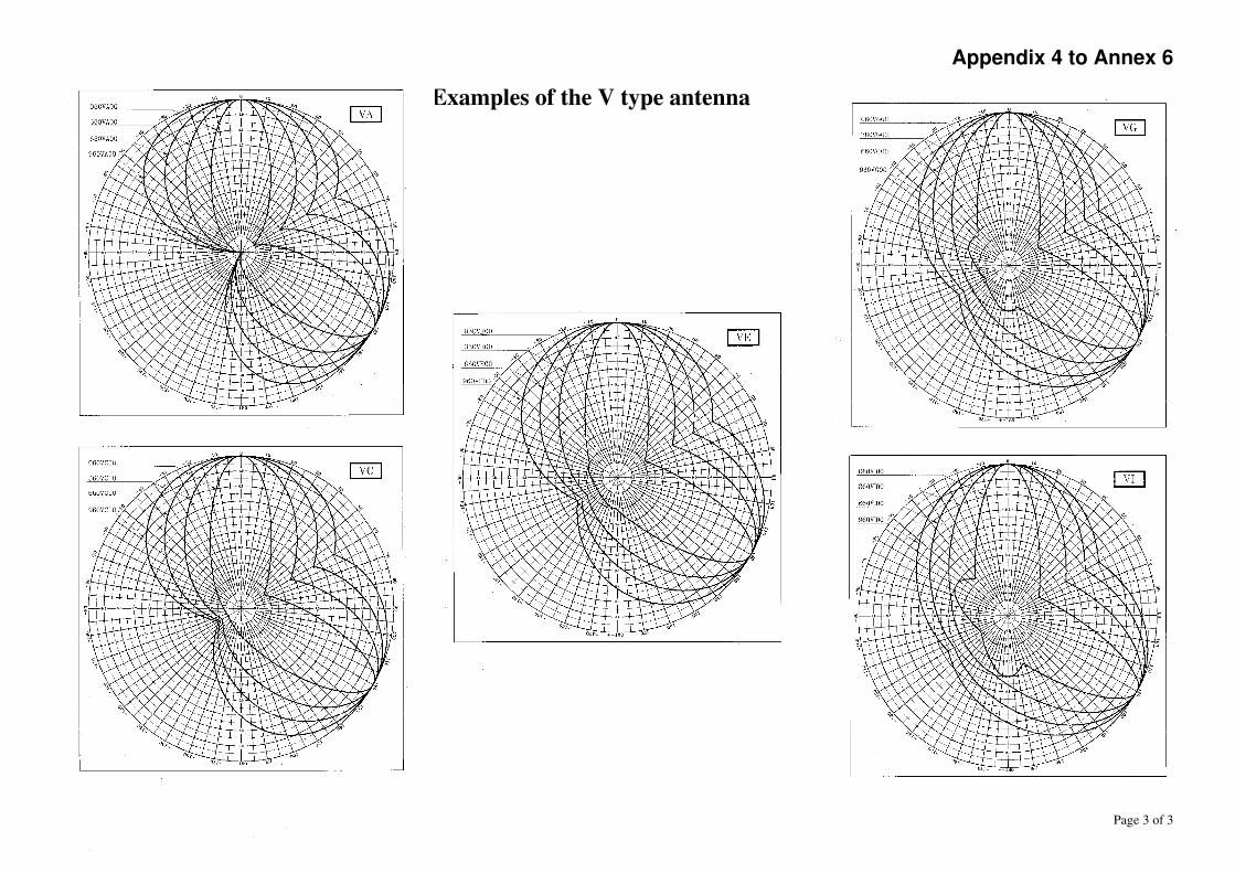
Appendix 4 to Annex 6
Page 3 of 3
Examples of the V type antenna

Appendix 5 to Annex 6
Page 1 of 3
W-type antenna diagrams (WA, WB, ... WH, WI)
This type of symmetrical radiation pattern diagram has two main beams. The basic curve is the same as in the case of the V-type, the difference lies in the enveloping radius having one value in the front direction and another in the back direction. The range of the enveloping radius is 0.35 to 0.80 in the front direction and 0.00 to 0.45 in the back direction.
The notation of the type is mnnWArp … mnnW I rp
With m = a one-digit number describing the half value of the half-power angle. nn = a two-digit number representing the half value of the angle between the
two main beams. r = a one-digit number characterising the radius of the circle enveloping the
side lobes on the back side. p = a one-digit number characterising the radius of the circle enveloping the
side lobes on the front side. Interpretation and range of the parameters:
= m 5 + 15 is the half value of the half-power angle.
0 < < 65
o
is automatically fulfilled because falls within 15 and 60 degrees due to the range of "m".
= nn is half of the opening angle between the main beams.
0 < There are no limitations on the maximum of the opening angle. However, it is reasonable to limit the half opening angle to be not greater than 90 degrees.
ro= r/20 is the enveloping radius of the side lobes in the back direction.
0 < ro < 1.0 is automatically fulfilled.
po= p/20 + 0.35 is the enveloping radius of the side lobes in the front direction.
0 < po < 1.0 is automatically fulfilled.
e is the shift of the extremity of the ellipses. 0 < e < 1/2 is automatically fulfilled.

Appendix 5 to Annex 6
Page 2 of 3
e 4th and 5th characters of the string
0.00 WA 0.05 WB 0.10 WC 0.15 WD 0.20 WE 0.25 WF 0.30 WG 0.35 WH 0.40 WI
The basic relations are : IF e=0 THEN e = 1E-5
2
52
1
e
k
2
5
2
52
2
1
2
cos
cos1*
2
ek
kb
5
2
4 kbk
5
2
3 ** kebk
35
4
2 * kkbk
2
1*2
1
ebk
5
2
4
3
2
21
cos*
cos*cos*
kxk
kxkxkr
i
The relative gain of the i-th
beam (i=1,2)
In the above equations, x is the running angle coordinate of the beams.
r1=fnct() is the relative gain of beam 1
r2=fnct(-2*) is the relative gain of beam 2
with being the current angle
The resulting pattern is formed by taking the maximum from r1, r2 and po calculated for any
given direction within the angular range of less than 180 degrees between the two main beams and taking the greatest from r1, r2 and ro calculated for any other given direction.
The field 9A of the data base must contain the azimuth of that main beam axis with respect to which the other one can be reached by a positive angular turn of less than 180 degrees.

Appendix 5 to Annex 6
Page 3 of 3
Examples of the W type antenna

Appendix 6 to Annex 6
Numerical value
Side lobe attenuation
90 0.9 = -1 dB
80 0.8 = -2 dB
70 0.7 = -3 dB
60 0.6 = -4.5 dB
50 0.5 = -6 dB
40 0.4 = -8 dB
30 0.3 = -10.5 dB
20 0.2 = -14.5 dB
10 0.1 = -20 dB
05 0.05 = -26 dB

Appendix 7 to Annex 6
= cos
n ..... for cos ()0
= 0 .............. for cos () < 0
n = - 0.1505 / log 10 (cos Definition range:
0.1° ≤ ≤ 89.0°
0° ≤ ≤ ± 180°

Appendix 8 to Annex 6
050PA00
250PK10
050PK10
890PZ00
Numerical value
Side lobe attenuation
90 0.9 = -1 dB
80 0.8 = -2 dB
70 0.7 = -3 dB
60 0.6 = -4.5 dB
50 0.5 = -6 dB
40 0.4 = -8 dB
30 0.3 = -10.5 dB
20 0.2 = -14.5 dB
10 0.1 = -20 dB
05 0.05 = -26 dB

Annex 7
Provisions on measurement procedures in the Fixed Service and the Land Mobile Service

Annex 7, page 2 of 6
PROVISIONS ON MEASUREMENT PROCEDURES
1. General Administrations concerned should agree upon measurements in the following cases: 1.1 in cases of disagreement concerning the results of evaluation related to a specific
coordination request (see section 4.8.2 of this Agreement)
1.2 to facilitate the enhancement of existing networks
(see section 4.8 of this Agreement) 1.3 in cases of harmful interference between coordinated links
(see section 5 of this Agreement) After receipt of the request for the application of the procedures mentioned above in points 1.1, 1.2 and 1.3, Administrations concerned shall endeavor that their Monitoring Services work closely together on the bases of internationally agreed measurement procedures. 2. Measurements Measurements shall be made according the latest version of the relevant CEPT/ECC/ERC Recommendation. 3. Report The Monitoring Services of the Administrations involved shall cooperate closely to draft a report of the measurement results. The results of measurements will be presented using the relevant form given in Appendices 1 and 2, depending upon the cases stated above.

Annex 7, page 3 of 6
Appendix 1 to Annex 7
MEASUREMENT REPORT ON COORDINATION BASED ON TESTS ASSIGNMENTS Existing assignment Coordination reference no. (13x): _________________________
Frequency (1a): _________________________
Location (4a): _________________________
Coordinates (4c): _________________________
Polarization (9d): _________________________ Requested assignment Coordination reference no. (13x): _________________________
Frequency (1a): _________________________
Location (4a): _________________________
Coordinates (4c): _________________________
Polarization (9d): _________________________ TYPE OF MEASUREMENT [ ] Fixed point, number of points: _____ [ ] Measurements over longer time periods [ ] Mobile MEASUREMENT DATA
Number of the measurement: _________________________
Measured frequency: _________________________
Measured bandwidth: _________________________
Date(s) of measurement: _________________________
Time period: _________________________

Annex 7, page 4 of 6
MEASUREMENT DATA (continued)
Location: _________________________ Geographical coordinates (deg/min/sec): _________________________
Altitude measurement location: _________ m above sea level
Height measurement antenna: ________ m above ground level
Polarization of measurement antenna: _________________________
Customer's antenna: [ ] yes [ ] no
Description of the transmission path1: __________________________
___________________________ ___________________________
Propagation conditions: ___________________________ ___________________________ ___________________________
Remarks: ___________________________ ___________________________ ___________________________
MEASUREMENT RESULTS In case of measurement over a longer time period: Quasi-maximum value (10 %): _____ dBµV/m
Quasi-minimum value (90 %): _____ dBµV/m
MEASURED VALUE2: _____ dBµV/m
1 to be indicated on a map, attached to this report in the case of mobile field strength
measurements 2 in case of measurement over longer time period or mobile measurement the median
value should be mentioned

Annex 7, page 5 of 6
Appendix 2 to Annex 7
MEASUREMENT REPORT ON HARMFUL INTERFERENCE ASSIGNMENTS Interfering assignment
Administration: _________________________
(b) Frequency: _________________________
(h) Supposed location: _________________________ or Direction to interfered assignment: _________________________
(c+d) Designation of emission (7a): _________________________
(e) Measured field strength: _____ dBµV/m
(f-x) other: __________________________
Remarks: __________________________
__________________________ __________________________
Interfered assignment Administration reference no. (13x): _________________________
Frequency (1a): _________________________
Location (4a): _________________________
Coordinates (4c): _________________________
Class of station (6a): _________________________ TYPE OF MEASUREMENT [ ] Fixed point, number of points: _____ [ ] Measurements over longer time periods [ ] Mobile

Annex 7, page 6 of 6
MEASUREMENT DATA
Number of the measurement: _________________________
Measured frequency: _________________________
Measured bandwidth: _________________________
Date(s) of measurement: _________________________
Time period: _________________________
Location: _________________________ Geographical coordinates (deg/min/sec): _________________________
Altitude measurement location: _________ m above sea level
Height measurement antenna: ________ m above ground level
Polarization of measurement antenna: _________________________
Customer's antenna: [ ] yes [ ] no
Description of the transmission path1: __________________________
___________________________ ___________________________
Propagation conditions: ___________________________ ___________________________ ___________________________
Remarks: ___________________________ ___________________________ ___________________________
MEASUREMENT RESULTS
In case of measurement over a longer time period: Quasi-maximum value (10 %): _____ dBµV/m
Quasi-minimum value (90 %): _____ dBµV/m
MEASURED VALUE2: _____ dBµV/m 1 to be indicated on a map, attached to this report in the case of mobile field strength
measurements 2 in case of measurement over longer time period or mobile measurement the median
value should be mentioned

Annex 8A
Method for combining the horizontal and vertical antenna patterns in the land mobile service

Annex 8A, page 2 of 7
1 The calculation of the 3-D antenna radiation pattern. The following description outlines how to calculate the 3-D antenna radiation pattern from the following input data of the Tx and Rx antennas:
- the partial horizontal and vertical antenna codes, respectively 9XH and 9XV, - the azimuth and elevation angles of maximum radiation, respectively 9A, 9B, - the azimuth and elevation angles of direction in which the resulting attenuation of
3-D antenna radiation pattern has to be calculated (propagation path). In a first step the two vectors (antenna direction and propagation path) are combined to one vector, represented by horizontal and vertical difference angle (hda, vda) that can be applied to the antenna in its basic position. This is done by plain spherical coordinate transformation. This step takes care of the azimuth and mechanical tilt (elevation) of the antenna. If the antenna has additional electrical tilt, it can now simply be applied to the resulting vertical difference angle as it is independent of the azimuth. With the resulting horizontal and vertical difference angle, the values for horizontal and vertical attenuation can be calculated according to the relevant antenna codes. The generally applied combination method to obtain the 3D-attenuation value is the geometrical sum. Due to reasons described in chapter 2, special cases have to be considered and taken care of to avoid inconsistencies.

Annex 8A, page 3 of 7
2 Combination of the partial horizontal and vertical radiation patterns into
resulting 3-D radiation pattern The resulting 3-D antenna radiation pattern is fully defined only in the two basic horizontal and vertical planes by the hCode and the vCode. The attenuation in random directions can only be evaluated by either a simple or a sophisticated approximation. The hCode and the vCode represent two upright cross-sections of resulting 3-D antenna radiation pattern, and therefore their back lobe attenuations have to be equal, as is demonstrated in Fig.2.
Fig.2. The existing reality is that some co-ordination requests contain mathematically incompatible antenna codes, as demonstrated in Fig.3.
Fig.3.

Annex 8A, page 4 of 7
One of reasons for this is that the applicant of the co-ordination request wants to express the intention that he does not want to claim any restrictions due to the vertical antenna code 000ND00 in conjunction with some directive horizontal antenna code. But this interpretation is nonsense from the mathematical point of view because it causes the ambiguity and the discontinuity of the resulting 3-D radiation pattern, as was demonstrated on Fig.3. The first step of combining the antenna diagrams is therefore to check whether they are compatible. If they are not compatible, then the vertical antenna diagram is adapted to conjunct the horizontal antenna diagram. The matching of both antenna diagrams together is performed by means of the following smoothing bridge function: AVD_back = AVD_back_O * SQR(sin2 vda + rb * cos2 vda) …….. [5] where: AVD_back is the attenuation of the matched vertical antenna back branch
AVD_back_O is the attenuation of the original (unchanged) vertical antenna back branch rb is back attenuation ratio of the original vertical and horizontal antenna diagrams at the angle vda = ± 180 deg.
The smoothing bridge function affects the back branch of the vertical antenna diagram only where it creates a new diagram shape, while its forward branch remains unchanged. The result of the matching adaptation process is demonstrated in the example given in Fig.4.
Fig.4. The back branch of the vertical antenna diagram with vda angle range from +90 to ± 180 deg. and from -90 to ± 180 deg. was continuously adapted to the existing back

Annex 8A, page 5 of 7
attenuation of the horizontal diagram for hda = 180 deg. The forward branch of the vertical antenna diagram remained omni-directional i.e. it remained unchanged. In the second step of the combination of the antenna diagrams, the resulting vertical antenna diagram is interpolated over different azimuth angles hda. The vertical antenna diagram consists of a forward and a back branch. The forward branch and the back branch of the vertical antenna diagram are eventually matched. (See Fig. 5)
Fig.5.
Two different types of interpolation are used: proportional and linear. The suitability of the interpolation type depends on the horizontal antenna diagram shape. The proportional interpolation of the source vertical antenna sub-diagrams is used for a directive multiple-lobe or for a one-lobe horizontal antenna diagram. The interpolation weight coefficient w is developed from the attenuation of the horizontal antenna diagram in the mentioned angle of hda and it is described by formula: w = (1 – h) / (1 – hb)
where: h is the attenuation of the horizontal antenna diagram in the azimuth hda
hb is the attenuation of the horizontal antenna diagram in the back direction (hda = 180 deg.)
Proportional interpolation assures, for example as given in Fig.4., that the vertical antenna diagrams will be identical in the symmetry hda axes of horizontal antenna diagrams 0, 120, 240 deg. The one-lobe directional horizontal antenna diagram case is shown in Fig.6.

Annex 8A, page 6 of 7
Fig.6. Fig.7.
Proportional interpolation type assures in the case of Fig.6. that the back branches of all vertical antenna diagrams will be identical in the hda azimuth range from 80 to 280 deg. due to constant attenuation of the horizontal antenna diagram there. Linear interpolation is used for slightly directive horizontal antenna diagrams only. An example of typical slightly directive horizontal antenna diagram is given in Fig.7. The interpolation weight coefficient w is developed from the angle interval between the forward azimuth angle and the back azimuth angle of hda, and it is described by formula:
w = ABS(hda / 180) The third step of the combination of partial antenna diagrams makes final checking whether the interpolated vertical antenna diagram and the horizontal antenna are compatible altogether in the evaluated azimuth hda. The reason for this last checking is demonstrated in Fig.8. If the pre-analyzed antenna diagrams are not compatible in some azimuth, then the partial vertical antenna diagram has to be adapted to the partial horizontal antenna diagram.

Annex 8A, page 7 of 7
Fig.8. The demo example, given in Fig.8., describes the case where both partial input antenna diagrams are compatible and both source vertical diagram branches are identical i.e. omni-directional. The pre-calculated omni-directional vertical diagram has to therefore be matched to the horizontal antenna diagram shape in azimuths where the attenuations of partial antenna diagrams are different, for example in the azimuth of hda = 45 deg. The matching of both partial antenna diagrams together is performed by means of a smoothing bridge function analogous to [5] described above.

Annex 8B, page 1 of 4
Annex 8B
Method for combining the horizontal and vertical antenna
patterns in the Fixed Service

Annex 8B, page 2 of 4
Three dimensional antenna pattern:
Vertical difference angle vda = Antenna_elevation(9B) – ETR, where ETR – vertical angle of the link e.g. between the antennas of interferer and interfered with stations. In case of line of sight,
for interferer ETR is calculated as follows:
ETR = (hr – ht) / distance – distance / (2 ae) rad,
where ht – interferer (transmitter) antenna height above sea level, hr – interfered with (receiver) antenna height above sea level, ae – effective Earth radius, distance – the distance between interferer and interfered with stations, for interfered with station ETR is calculated as follows: ETR = (ht - hr) / distance – distance / (2 ae), rad,
In case of transhorizon path,
for interferer ETR is calculated as follows:
ETR = Θt / 1000 rad,
where Θt – interferer (transmitter) radio horizon angle (mrad),

Annex 8B, page 3 of 4
for interfered with station ETR is calculated as follows: ETR = Θr / 1000 rad, where Θr – interfered with (receiver) radio horizon angle (mrad).
The maximum difference angle in the horizontal plane (hda) is 180 degrees, the maximum
difference angle in the vertical plane (vda) is also 180 degrees. The resulting total difference angle (tda) is between 0 and 180 degrees. The tda value is calculated using formula:
tda = arccos ( sin(Antvert) sin(vda) + cos(Antvert) cos(vda) * cos(hda-Anthor) )
where Antvert = difference angle between antenna elevation and elevation of the link and Anthor = difference angle between antenna azimuth and azimuth of the link. Because Antvert and Anthor are 0, the resulting formula is: tda = arccos ( cos(vda) * cos(hda)) Taking into account this total difference angle, the antenna attenuation for the horizontal plane (Ahor) and for the vertical plane (Avert) are calculated. If the horizontal antenna pattern is not symmetrical and the horizontal difference angle (hda) is negative (or between 180 and 360 degrees), the attenuation for the horizontal plane is calculated using the negative total difference angle (-tda). If the vertical antenna pattern is not symmetrical and the vertical difference angle (vda) is negative (or between 180 and 360 degrees), the attenuation for the vertical plane is calculated using the negative total difference angle (-tda).

Annex 8B, page 4 of 4
If both values for attenuation are equal, the resulting attenuation (Aresulting) is equal to one of those values: Aresulting = Ahor or Aresulting = Avert
If the horizontal attenuation is greater than the vertical attenuation, the resulting attenuation (Aresulting) is:
Aresulting = Avert + (Ahor – Avert) Abs(hda) / (Abs(hda) + Abs(vda)) If the vertical attenuation is greater than the horizontal attenuation, the resulting attenuation (Aresulting) is:
Aresulting = Ahor + (Aver – Ahor) Abs(vda) / (Abs(hda) + Abs(vda)) This value Aresulting is used for further calculations.

Annex 9
Threshold Degradation in the Fixed Service

Annex 9 page 2 of 8
Permissible Threshold Degradation 1 Definition of Threshold Degradation (TD) The Threshold of a radio receiver is defined as the level of the wanted signal received for a given Bit Error Rate (BER). In presence of an interfering signal ( I ), the level of the received wanted signal must be increased to preserve the same BER. For a given BER, the difference between the increased threshold level value due to interference, and the threshold value without interference, is the Threshold Degradation (TD). TD is assumed to be equivalent to the noise level increase, due to the interfering signal at the input of the receiver. 2 Permissible Threshold Degradation The Permissible Threshold Degradation caused to one fixed-link receiver by one foreign fixed-link transmitter must not exceed 1 dB. 3 Calculation of Threshold Degradation The calculation of TD is a two-step process. First, the interfering power level ( I ) at the input of the receiver must be calculated. Then, the TD due to this interfering signal is calculated and compared to the 1 dB permissible value.

Annex 9 page 3 of 8
Figure 1 illustrates the mechanism of the interference caused by transmitter X on receiver U.
A
B
aRx
C
Waveguide
D
GR
Interfering signal
Wanted
signal
GT
D´
Waveguide
C
aTx
B´
A´
Fig. 1
I
Station Y
Station X
Station U
Station V
PTx
Branching
circuit
Transmitter
filter
Transmitter
X
Branching
circuit
Receiver
filter
Receiver
U

Annex 9 page 4 of 8
3.1 Calculation of the interfering power level I a) The technical data necessary for the calculation of different intermediate parameters, and finally the interfering signal power level ( I ) at the input of an interfered receiver, are listed below: Interfered receiver: - fRx (MHz) : receiver frequency
- geographical coordinates - terrain height (m) above sea level - antenna height (m) above terrain level - main beam direction of the antenna - GR (dB) : receiver antenna gain - aRx (dB) : receiver attenuation between points D and A (all losses between the
antenna flange and the input of the receiver) - co-polar and cross polar receiver antenna radiation pattern - receiver selectivity mask ( possibly assumed, see Annex 3 B) - polarisation
Interfering transmitter:
- fTx (MHz) : transmitter frequency - PTx (dBW) : transmitter power level - geographical coordinates - terrain height (m) above sea level - antenna height (m) above terrain level - main beam direction of the antenna - GT (dB) : transmitter antenna gain - aTx (dB) : transmitter attenuation between points D’ and A’ (all losses between the
antenna flange and the output of the transmitter) - Co-polar and cross polar transmitter antenna radiation pattern - Transmitter spectrum mask (see Annex 3 B) - ATPC (dB) : dynamic range of automatically transmitter power control (when
applicable) -polarisation
b) The interfering power level ( I ) at the receiver input at the station U can be determined using:
totTx aPI (dBW) (1.1)
where atot [dB] total attenuation between transmitter output (point A´) and receiver input (point A)

Annex 9 page 5 of 8
atot = aTx - GTx + aprop - GRx + aRx + aant + MD + NFD + ATPC (dB) (1.2)
where NFD (dB) Net Filter Discrimination (see Annex 3B for calculation) MD (dB) Masks Discrimination (see Annex 3B for calculation) aprop [dB] propagation attenuation between antennas that can be calculated on the basis of the
results of calculation covered in the Annex 10, in conformity with the type of path. aant [dB] attenuation which is a function of both antenna radiation patterns and polarisation
discrimination The aggregated antennas attenuation aant due to both antenna radiation patterns and polarisation discriminations can be determined using the following formula:
20101log20
antVantHaa
antHantaa (dB),
where:
aantH aggregated antennas (transmitting and receiving) attenuation for signal of H polarisation,
aantV aggregated antennas attenuation for signal of V polarisation.
aantH and aantV for different configuration of antennas polarisation can be determined by formulas given in the Table 1 where the following notation is applied:
aTH-H attenuation of the transmitter antenna of polarisation H relating to the signal of H polarisation in the direction of the receiver,
aTV-V attenuation of the transmitter antenna of polarisation V relating to the signal of V polarisation in the direction of the receiver,
aTH-V attenuation of the transmitter antenna of polarisation H relating to signal with V polarisation in the direction of the receiver,
aTV-H attenuation of the transmitter antenna of polarisation V relating to signal with H polarisation in the direction of the receiver,
aRH-H attenuation of the receiver antenna of polarisation H relating to the signal of H polarisation in the direction of the transmitter,
aRV-V attenuation of the receiver antenna of polarisation V relating to the signal of V polarisation in the direction of the transmitter,
aRH-V attenuation of the receiver antenna of polarisation H relating to the signal of V polarisation in the direction of the transmitter,
aRV-H attenuation of the receiver antenna of polarisation V relating to the signal of H polarisation in the direction of the transmitter,

Annex 9 page 6 of 8
Table 1
aantH and aantV for different configuration of antennas polarisation
Transmitter antenna Receiver antenna polarisation
Polarisation H V
H aantH = aTH-H + aRH-H
aantV = aTH-V + aRH-V
aantH = aTH-H + aRV-H
aantV = aTH-V + aRV-V
V aantH = aTV-H + aRH-H
aantV = aTV-V + aRH-V
aantH = aTV-H + aRV-H
aantV = aTV-V + aRV-V
3.2 Calculation of TD due to I a) Input data I (dBW) : interfering power level at the receiver input coming from one interfering
source (see 3.1.b). FkTB or N (dBW) : noise power level in the interfered receiver bandwidth. b) Calculation: TD (dB) , threshold degradation of the interfered receiver TD = 10 log (1 + 10 ( I - N) / 10 ) (1.3)
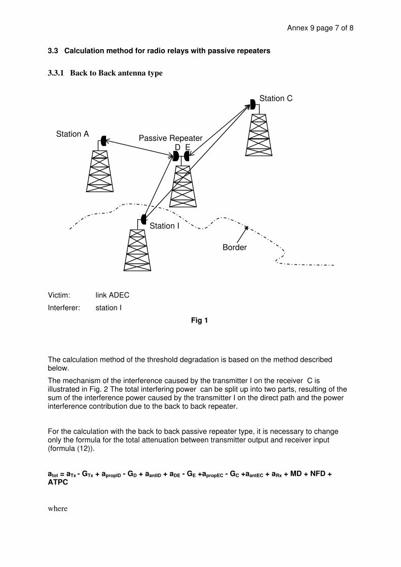
Annex 9 page 7 of 8
3.3 Calculation method for radio relays with passive repeaters
3.3.1 Back to Back antenna type
Victim: link ADEC
Interferer: station I
Fig 1
The calculation method of the threshold degradation is based on the method described below.
The mechanism of the interference caused by the transmitter I on the receiver C is illustrated in Fig. 2 The total interfering power can be split up into two parts, resulting of the sum of the interference power caused by the transmitter I on the direct path and the power interference contribution due to the back to back repeater.
For the calculation with the back to back passive repeater type, it is necessary to change only the formula for the total attenuation between transmitter output and receiver input (formula (12)).
atot = aTx - GTx + apropID - GD + aantID + aDE - GE +apropEC - GC +aantEC + aRx + MD + NFD + ATPC
where
Passive Repeater D E
Station A
Station C
Station I
Border

Annex 9 page 8 of 8
apropID [dB] propagation attenuation between antennas I and D that can be calculated on the basis of the result of calculation covered in Annex 10. In conformity with the type of path.
apropEC [dB] propagation attenuation between antennas E and C that can be calculated on the basis of the result of calculation covered in Annex 10. In conformity with the type of path.
aantID [dB] attenuation which is a function of antennas I and D radiation patterns and polarisation discrimination.
aantEC[dB] attenuation which is a function of antennas E and C radiation patterns and polarisation discrimination.
aDE [dB] attenuation between antennas D and E (wave guide attenuation).
3.3.2 Plane reflector
Interference at the reflector only needs to be considered if it arrives from the same direction as the wanted signal. Consequently, plane reflectors have to be taken into account in the national coordination process, but can be neglected during international coordination.

Annex 10, page 1 of 19
Annex 10, page 1
Annex 10
Determination of the basic transmission loss in the Fixed Service

Annex 10, page 2 of 19
Annex 10, page 2
PREDICTION PROCEDURE FOR THE EVALUATION OF BASIC TRANSMISSION LOSS
1 Introduction The prediction procedure provided in this chapter is based on the Recommendation ITU-R P.452-13. The procedure is appropriate to radio relay links operating in the frequency range of about 0.7 GHz to 50 GHz. The method includes a complementary set of propagation models, which ensure that the predictions embrace all the significant propagation mechanisms relevant to long-term interference. Methods for analysing the radio-meteorological and topographical features of the path are provided so that predictions can be prepared for any practical interference path falling within the scope of the procedure. The prediction is achieved in four steps described in the sections 3, 4, 5 and 6.
2 Bases for the models used in the prediction It is assumed that interference, which is significant during a small percentage of time (short-term) can not deteriorate the performance and the ability of the transmission. As a result of that assumption, only long-term interference is taken into account, and therefore the time percentage, for which the calculated basic transmission loss is not exceeded, is taken as 20%. Accordingly, the procedure uses four propagation models listed below: line-of-sight (including signal enhancements due to multipath and focusing effects); diffraction (embracing smooth-Earth, irregular terrain and sub-path cases); tropospheric scatter; surface ducting and layer reflection. Depending on the type of path, as determined by a path profile analysis, one or more of these models are exercised in order to provide the required prediction of basic transmission loss. The propagation prediction models predict the average annual distribution of basic transmission loss. As the radio-meteorological and topographical features for the terrain of all signatory’s countries appeared to be almost the same, the common values were adopted. The values for such parameters are as follows:
N : the average radio-refractive index lapse-rate through the lowest 1 km of the atmosphere, (N-units/km) = 45
N0: the sea-level surface refractivity, (N-units)= 325
p : Pressure = 1013 hPa t : temperature = 15 C

Annex 10, page 3 of 19
Annex 10, page 3
3 Step 1 of the prediction procedure: Preparation of the input data The basic input data required for the procedure is given in Table1. All other information required is derived from these basic data during the execution of the procedure.
TABLE 1
Basic input data
Parameter Preferred resolution Description
f 0.00001 Frequency (GHz)
t, r 1 Latitude of station (seconds)
p 1 Required time percentage(s) for which the calculated basic transmission loss is not exceeded
t, r 1 Longitude of station (seconds)
htg, hrg 1 Antenna centre height above ground level (m)
hts, hrs 1 Antenna centre height above mean sea level (m)
Gt, Gr 0.1 Antenna gain in the direction of the horizon along the great-circle interference path (dBi)
NOTE 1 For the interfering and interfered-with stations:
t: interferer r: interfered-with station
4 Step 2 of the prediction procedure: Radiometeorological data The values of radio-meteorological parameters, which could be determined as common to all countries of West, South and Central Europe are given in § 2. In the prediction procedure the time percentage for which refractive index lapse-rates exceeding 100 N-units/km can be
expected in the first 100 m of the lower atmosphere, 0 (%) must be evaluated. This parameter
is used to estimate the relative incidence of fully developed anomalous propagation at the
latitude under consideration. The value of 0 to be used is that appropriate to the path centre
latitude. Point incidence of anomalous propagation, 0 (%), for the path centre location is
determined using:
(i)
70for%μμ17.4
70for%μμ10β41
4167.1015.0
0 (1.)
where : path centre latitude (degrees) which is not greater than 70 and not less than
-70

Annex 10, page 4 of 19
Annex 10, page 4
The parameter 1 depends on the degree to which the path is over land (inland and/or coastal)
and water, and is given by:
1
16 6 6 0 496 0 3545
0 2
10 10
dtm
. . .
.
(2.)
where the value of 1 shall be limited to 1 1,
with:
14 12 10 4 2 41
e. .
dlm (3.)
where dtm : longest continuous land (inland + coastal) section of the great-circle
path (km) dlm : longest continuous inland section of the great-circle path (km)
The radioclimatic zones to be used for the derivation of dtm and dlm are defined in Table 2.
70for10
70for10μ1
1
μlog3.0
μlog)0176.0935.0(
4 (4.)
TABLE 2
Radio-climatic zones
Zone type Code Definition
Coastal land A1 Coastal land and shore areas, i.e. land adjacent to the sea up to an altitude of 100 m relative to mean sea or water level, but limited to a distance of 50 km from the nearest sea area. Where precise 100 m data is not available an approximate value may be used
Inland A2 All land, other than coastal and shore areas defined as “coastal land” above
Sea B Seas, oceans and other large bodies of water (i.e. covering a circle of at least 100 km in diameter)
Large bodies of inland water A “large” body of inland water, to be considered as lying in Zone B, is defined as one having an
area of at least 7 800 km2, but excluding the area of rivers. Islands within such bodies of water are to be included as water within the calculation of this area if they have elevations lower than 100 m above the mean water level for more than 90% of their area. Islands that do not meet these criteria should be classified as land for the purposes of the water area calculation. Large inland lake or wet-land areas
Large inland areas of greater than 7 800 km2, which contain many small lakes or a river network should be declared as “coastal” Zone A1 by administrations if the area comprises more than 50% water, and more than 90% of the land is less than 100 m above the mean water level. Climatic regions pertaining to Zone A1, large inland bodies of water and large inland lake and

Annex 10, page 5 of 19
Annex 10, page 5
wetland regions, are difficult to determine unambiguously. Therefore administrations are requested to register with the TWG HCM those regions within their territorial boundaries that they wish identified as belonging to one of these categories. In the absence of registered information to the contrary, all land areas will be considered to pertain to climate Zone A2. Effective Earth’s radius The median effective Earth radius factor k50 for the path is determined using:
Nk
±157
15750 (5.)
Assuming a true Earth radius of 6 371 km and the average radio-refractive index N (N-units/km) for West, South and Central Europe of 45, the median value of effective Earth radius ae [km] can be determined from:
ae = 6371 · k50 (6.)
The effective Earth radius [km] exceeded for 0% time, a, is given by:
a = 6 371 · k (7.)
where k = 3.0 is an estimate of the effective Earth radius factor exceeded for 0% time.
5 Step 3 of the prediction procedure: Path profile analysis Values for a number of path-related parameters necessary for the calculations, as indicated in Tables 3 and 4, must be derived via an initial analysis of the path profile based on the value of ae given by equation (6.). For path profile analysis, a path profile of terrain heights above mean
sea level is required. Having thus analysed the profile, the path will also have been classified into transhorizontal or line of sight.

Annex 10, page 6 of 19
Annex 10, page 6
TABLE 3
Parameter values to be derived from the path profile analysis
Parameter Description
d Great-circle path distance (km)
dlt, dlr For a transhorizon path, distance from the transmit and receive antennas to their respective horizons (km). ). For a line-of-sight path, each is set to the distance from the terminal to the profile point identified as the principal edge in the diffraction method for 50% time.
t, r For a transhorizon path, transmit and receive horizon elevation angles respectively (mrad). For a line-of-sight path, each is set to the elevation angle of the other terminal.
Path angular distance (mrad)
hts, hrs Antenna centre height above mean sea level (m)
db Aggregate length of the path sections over water (km)
Fraction of the total path over water:
= db /d (8.)
where d is the great-circle distance (km)
For totally overland paths = 0
dct, dcr
Distance over land from the transmit and receive antennas to the coast along the great-circle interference path (km). Set to zero for a terminal on a ship or sea platform.

Annex 10, page 7 of 19
Annex 10, page 7
5.1 Construction of path profile
Based on the geographical co-ordinates of the interfering (t, t) and interfered-with (r, r)
stations, terrain heights (above mean sea level) along the great-circle path should be derived from a topographical database or from appropriate large-scale contour maps. The preferred distance resolution of the profile is that giving an integer number of steps of 0.1 km. The profile should include the ground heights at the interfering and interfered-with station locations as the start and end points. To the heights along the path should be added the necessary Earth’s curvature, based on the value of ae found in equation (6.).
For the purposes of this Annex the point of the path profile at the interferer is considered as point 0, and the point at the interfered-with station is considered as point n. The path profile therefore consists of n + 1 points. Figure 1 gives an example of a path profile of terrain heights above mean sea level, showing the various parameters related to the actual terrain. Table 4 defines parameters used or derived during the path profile analysis. The path length, d (km), should be calculated according to the formula related to the great circle distance:
d =6371· arccos(sin(φt) sin(φr) + cos(φt) cos(φr) cos( t – r)) (9.)
rsh
lrd
hrg
hgr
r
d
dlt
d i
t
tgh
gth
lh
hts
ae=k50a
Interfering station (T)M ean sea level
Interfered-withstation (R)
ith terrain point
FIGURE 1
Example of a (trans-horizon) path profile
Note 1 – The value of as drawn will be negative. t

Annex 10, page 8 of 19
Annex 10, page 8
TABLE 4
Path profile parameter definitions
Parameter Description
ae Effective Earth’s radius (km)
d Great-circle path distance (km)
di Great-circle distance of the i-th terrain point from the interferer (km)
dii Incremental distance for regular path profile data (km)
f Frequency (GHz)
Wavelength (m)
hts Interferer antenna height (m) above mean sea level (amsl)
hrs Interfered-with antenna height (m) (amsl)
t For a transhorizon path, horizon elevation angle above local horizontal (mrad), measured from the interfering antenna. For a line-of-sight path this should be the elevation angle of the interfered-with antenna
r For a transhorizon path, horizon elevation angle above local horizontal (mrad), measured from the interfered-with antenna. For a line-of-sight path this should be the elevation angle of the interfering antenna
5.2 Path classification The path must be classified into line-of-sight or transhorizon. The path profile must be used to determine whether the path is line-of-sight or transhorizon based on the median effective Earth’s radius of ae. A path is trans-horizon if the physical horizon elevation angle as seen by the interfering antenna (relative to the local horizontal) is greater than the angle (again relative to the interferer’s local horizontal) subtended by the interfered-with antenna. The test for the trans-horizon path condition is thus:
(mrad) max td (10.)
where:
(mrad) )(max1
1max i
n
i
(11.)
i : elevation angle to the i th terrain point
(mrad) 2
10- =
3
e
i
i
tsi
ia
d
d
hh (12.)
where: hi : height of the i th terrain point (m) amsl
hts : interferer antenna height (m) amsl
di : distance from interferer to the i th terrain element (km)
(mrad) 2
10- =
3
e
tsrs
tda
d
d
hh (13.)
where: hrs : interfered-with antenna height (m) amsl
d : total great-circle path distance (km) ae : median effective Earth’s radius appropriate to the path (equation (6.)).

Annex 10, page 9 of 19
Annex 10, page 9
Derivation of parameters from the path profile for trans-horizon paths The parameters to be derived from the path profile are those contained in Table 4.
Interfering antenna horizon elevation angle, t
The interfering antenna’s horizon elevation angle is the maximum antenna horizon elevation angle when equation (11.) is applied to the n – 1 terrain profile heights.
mrad)( max t (14.)
with max as determined in equation (11.).
Interfering antenna horizon distance, dlt
The horizon distance is the minimum distance from the transmitter at which the maximum antenna horizon elevation angle is calculated from equation (11.).
)max( (km) iilt fordd (15.)
Interfered-with antenna horizon elevation angle, r The receive antenna horizon elevation angle is the maximum antenna horizon elevation angle when equation (11.) is applied to the n – 1 terrain profile heights.
(mrad) )(max1
1jr
n
j
(16.)
(mrad) 2
)(10- =
3
e
j
j
rsji
ja
dd
dd
hh
(17.)
Angular distance θ (mrad) The angular distance is calculated using formula :
= ea
d3
10 + t + r (mrad) (18.)
Interfered-with antenna horizon distance, dlr
The horizon distance is the minimum distance from the receiver at which the maximum antenna horizon elevation angle is calculated from equation (11.). dlr = d - d j (km) for max(Θj) (19.)

Annex 10, page 10 of 19
Annex 10, page 10
6 Step 4 of the prediction procedure: Calculation of propagation predictions Basic transmission loss, Lb (dB), not exceeded for the required annual percentage time, p, is evaluated as described in the following sub-sections.
6.1 Line-of-sight propagation (including short-term effects) The following should be evaluated for both line-of-sight and transhorizon paths. Basic transmission loss due to free-space propagation and attenuation by atmospheric gases:
Lbfsg = 92.5 + 20 log f + 20 log d + Ag dB (20.)
where: Ag : total gaseous absorption (dB):
dB)()( dA wog (21.)
where:
o, w() : specific attenuation due to dry air and water vapour, respectively, and are
found from the equations (23.), (24.)
: water vapour density: ρ = 7.5 + 2.5 (g/m3) (22.)
: fraction of the total path over water.
For dry air, the attenuation o (dB/km) is given by Recommendation ITU-R P.676-7 as follows:
322
216.1
3
6.122
8.2
1083.0)54(
62.0
34.0
2.7
1
p
tp
to rf
frrf
r (23.)
where: f : frequency (GHz) rp = p / 1013
rt = 288/(273 + t)
p : pressure (hPa) - see § 2
t : temperature (C) see § 2.
)6515.1,0156.0,8132.1,0717.0,,(1 tp rr
)7416.5,1921.0,6368.4,5146.0,,(2 tp rr
)5854.8,2130.0,5851.6,3414.0,,(3 tp rr
)]1()1(exp[),,,,,( tpbt
aptp rdrcrrdcbarr
For water vapour, the attenuation w (dB/km) is given by:

Annex 10, page 11 of 19
Annex 10, page 11
45.22
2
24
2
1
2
1
2
1
2
1
21
2
1
21
2
1
21
2
1
21
2
1
10)7801,()7801(
)]1(99.0exp[103328.8
)752,()752(
)]1(41.0exp[290)557,(
)557(
)]1(17.0exp[6.844
)448(
)]1(46.1exp[4.17
)380(
)]1(09.1exp[37.25
22.9)153.325(
)]1(6.1exp[66.3
29.6)226.321(
)]1(44.6exp[081.0
14.11)31.183(
)]1(7.0exp[96.11)22,(
42.9)235.22(
)]1(23.2exp[98.3
tt
tt
tt
tt
ttw
rffgf
r
fgf
rfg
f
r
f
r
f
r
f
r
f
r
f
rfg
f
r
(24.)
where:
006.0955.0 68.01 tprr
45.02 0353.0735.0 ttp rrr
2
1),(
i
ii
ff
ffffg
Corrections for multipath and focusing effects at p and 0 percentage times:
Esp = 2.6 [1 exp(–0.1 dlt + dlr)] log (p/50) dB (25.)
Es = 2.6 [1 exp(–0.1 dlt + dlr)] log (0/50) dB (26.) Basic transmission loss not exceeded for time percentage, p%, due to line-of-sight propagation: Lb0p = Lbfsg + Esp dB (27.)
Basic transmission loss not exceeded for time percentage, 0%, due to line-of-sight propagation:
Lb0 = Lbfsg + Es dB (28.)
6.2 Diffraction The diffraction model calculates the following quantities required in § 6.5: Ldp: diffraction loss not exceeded for p% time Lbd50: median basic transmission loss associated with diffraction Lbd: basic transmission loss associated with diffraction not exceeded for p% time. The diffraction loss is calculated for all paths using a hybrid method based on the Deygout construction and an empirical correction. This method provides an estimate of diffraction loss for all types of paths, including over-sea or over-inland or coastal land, and irrespective of whether the land is smooth or rough. This method should be used, even if the edges identified by the Deygout construction are adjacent profile points. This method also makes extensive use of an approximation to the single knife-edge diffraction
loss as a function of the dimensionless parameter, , given by:
1.011.0log209.6)(
2J (29.)

Annex 10, page 12 of 19
Annex 10, page 12
Note that J(–0.78)0, and this defines the lower limit at which this approximation should be used. J( ) is set to zero for <–0.78.
6.2.1 Median diffraction loss The median diffraction loss, Ld50 (dB), is calculated using the median value of the effective Earth radius, ae, given by equation (6.). Median diffraction loss for the principal edge
Calculate a correction, m, for overall path slope given by:
d
hh tsrsm
31 10tancos (30.)
Find the main (i.e. principal) edge, and calculate its diffraction parameter, m50, given by:
iiim
n
im
ddd
dH
31
150
102max , (31.)
where the vertical clearance, Hi, is:
d
dhddh
a
dddhH irsits
e
iiii
2103
(32.)
and
hts,rs : transmitter and receiver heights above sea level (m) (see Table3.)
: wavelength (m) = 0.3/f f : frequency (GHz) d : path length (km) di : distance of the i-th profile point from transmitter (km) (see § 5.2) hi : height of the i-th profile point above sea level (m) (see § 5.2).
Set im50 to the index of the profile point with the maximum value, m50. Calculate the median knife-edge diffraction loss for the main edge, Lm50, given by:
otherwise 0 78.0 if 505050
mmm JL
(33.)
If Lm50 = 0, the median diffraction loss, Ld50, and the diffraction loss not exceeded for 0% time,
Ld, are both zero and no further diffraction calculations are necessary. Otherwise possible additional losses due to secondary edges on the transmitter and receiver sides of the principal edge should be investigated, as follows. Median diffraction loss for transmitter-side secondary edge If im50 = 1, there is no transmitter-side secondary edge, and the associated diffraction loss, Lt50,
should be set to zero. Otherwise, the calculation proceeds as follows. Calculate a correction, t, for the slope of the path from the transmitter to the principal edge:
50
5031 10tancos
mi
tsmit
d
hh (34.)
Find the transmitter-side secondary edge and calculate its diffraction parameter, t50 , given by:

Annex 10, page 13 of 19
Annex 10, page 13
imii
miit
i
it
ddd
dH
m
50
5031
150
102max
50
(35.)
where:
50
5050503
210
mi
imiimits
e
imiiii
d
dhddh
a
dddhH
(36.)
Set it50 to the index of the profile point for the transmitter-side secondary edge (i.e. the index of the terrain height array element corresponding to the value t50). Calculate the median knife-edge diffraction loss for the transmitter-side secondary edge, Lt50, given by:
otherwise 0
2 and 78.0for 50505050
mttt iJL (37.)
Median diffraction loss for the receiver-side secondary edge If im50 = n-1, there is no receiver-side secondary edge, and the associated diffraction loss, Lr50,
should be set to zero. Otherwise the calculation proceeds as follows. Calculate a correction, r, for the slope of the path from the principal edge to the receiver:
50
5031 10tancos
mi
mirsr
dd
hh (38.)
Find the receiver-side secondary edge and calculate its diffraction parameter, r50 , given by:
imii
miir
n
iir
dddd
ddH
m 50
5031
150
102max
50
(39.)
where:
50
5050503
210
mi
miirsimi
e
imiiii
dd
ddhddh
a
ddddhH
(40.)
Set ir50 to the index of the profile point for the receiver-side secondary edge (i.e. the index of the terrain height array element corresponding to the value r50). Calculate the median knife-edge diffraction loss for the receiver-side secondary edge, Lr50, given by:
otherwise 0
1 and 78.0for 50505050
niJL mrrr (41.)
Combination of the edge losses for median Earth curvature Calculate the median diffraction loss, Ld50, given by:
otherwise 0
78.0for 04.010e1 5050506
5050
50
mrt
L
md dLLLL
m
(42.)
In equation (42.) Lt50 will be zero if the transmitter-side secondary edge does not exist and, similarly, Lr50 will be zero if the receiver-side secondary edge does not exist.
If Ld50 = 0, then the diffraction loss not exceeded for 0% time will also be zero. If the prediction is required only for p = 50%, no further diffraction calculations will be necessary
(see § 6.2.3). Otherwise, the diffraction loss not exceeded for 0% time must be calculated, as

Annex 10, page 14 of 19
Annex 10, page 14
follows.
6.2.2 The diffraction loss not exceeded for 0% of the time
The diffraction loss not exceeded for 0% time is calculated using the effective Earth radius
exceeded for 0% time, a, given by equation (7.). For this second diffraction calculation, the same edges as those found for the median case should be used for the Deygout construction. The calculation of this diffraction loss then proceeds as follows.
Principal edge diffraction loss not exceeded for 0% time
Find the main (i.e. principal) edge diffraction parameter, m, given by:
5050
3102
mimimimm
ddd
dH
(43.)
where:
d
dhddh
a
dddhH mirsmitsmimi
mimi505050503
50 210
(44.)
Calculate the knife-edge diffraction loss for the main edge, Lm, given by:
otherwise 0
78.0for
mmm JL
(45.)
Transmitter-side secondary edge diffraction loss not exceeded for 0% time
If Lt50 = 0, then Lt will be zero. Otherwise calculate the transmitter-side secondary edge
diffraction parameter, t, given by:
505050
503102
timiti
mititt
ddd
dH
(46.)
where:
50
50505050505050350 2
10
mi
timitimitstimitititi d
dhddh
a
dddhH
(47.)
Calculate the knife-edge diffraction loss for the transmitter-side secondary edge, Lt, given by:
otherwise 0
78.0for
ttt JL
(48.)
Receiver-side secondary edge diffraction loss not exceeded for 0% time
If Lr50 = 0, then Lr will be zero. Otherwise, calculate the receiver-side secondary edge diffraction
parameter, r, given by:
505050
503102
rimiri
mirirr
dddd
ddH
(49.)
where:

Annex 10, page 15 of 19
Annex 10, page 15
50
505050505050350 2
10
mi
mirsrimirimiririri dd
ddhddh
a
ddddhH
(50.)
Calculate the knife-edge diffraction loss for the receiver-side secondary edge, Lr, given by:
otherwise 0
78.0for
rrr JL
(51.)
Combination of the edge losses not exceeded for 0% time
Calculate the diffraction loss not exceeded for 0% of the time, Ld, given by:
otherwise 0
78.0for 04.010e1 6
mrt
L
md dLLLL
m
(52.)
6.2.3 The diffraction loss not exceeded for p% of the time The application of the two possible values of effective Earth radius factor is controlled by an interpolation factor, Fi, based on a log-normal distribution of diffraction loss over the range
0% < p < 50%. given by: Fi = 0 p = 50% (53.)
=
100
100
0I
pI
for 50% > p > 0% (54.)
= 1 for 0% p (55.) where I(x) is the inverse cumulative normal function. An approximation for I(x) which may be used with confidence for x < 0.5 is given in (59.). The diffraction loss, Ldp, not exceeded for p% time, is now given by:
Ldp = Ld50 + Fi ( Ld – Ld50) dB (56.)
where Ld50 and Ld are defined by equations (42.) and (52.), respectively, and Fi is defined by
equations (53. to 55.), depending on the values of p and 0. The median basic transmission loss associated with diffraction, Lbd50, is given by: Lbd50 = Lbfsg + Ld50 dB (57.) where Lbfsg is given by equation (20.). The basic transmission loss associated with diffraction not exceeded for p% time is given by: Lbd = Lb0p + Ldp dB (58.) where Lb0p is given by equation (27.). The following approximation to the inverse cumulative normal distribution function is valid for
0.000001 x 0.5 and is in error by a maximum of 0.00054. It may be used with confidence for
the interpolation function in equation (54.). If x < 0.000001, which implies 0 < 0.0001%, x

Annex 10, page 16 of 19
Annex 10, page 16
should be set to 0.000001. The function I(x) is then given by:
I(x) = (x) – T(x) (59.) where:
xxT ln2)( (60.)
1)()()(=)(
123
012
xTDxTDxTD
CxTCxTCx (61.)
C0 = 2.515516698 (62.)
C1 = 0.802853 (63.)
C2 = 0.010328 (64.)
D1 = 1.432788 (65.)
D2 = 0.189269 (66.)
D3 = 0.001308 (67.)
6.3 Tropospheric scatter The basic transmission loss due to troposcatter, Lbs (p) (dB) not exceeded for any time
percentage, p, is given by:
7.00 )50/(log–1.10–15.0–θ573.0log20190 pALNdLL gcfbs (68.)
where: Lf : frequency dependent loss:
Lƒ= 25logƒ-2.5[log(ƒ/2)]2 (dB) (69.)
Lc : aperture to medium coupling loss (dB):
(dB)·051.0 )(055.0 rt GG
c eL (70.)
Ag: gaseous absorption derived from equation (21.) using = 3 g/m3 for the whole path length
6.4 Ducting/layer reflection The prediction of the basic transmission loss, Lba (dB) occurring during periods of anomalous propagation (ducting and layer reflection) is based on the following function: Lba = Af + Ad ( p) + Ag dB (71.) where: Af : total of fixed coupling losses (except for local clutter losses) between the antennas and the anomalous propagation structure within the atmosphere:

Annex 10, page 17 of 19
Annex 10, page 17
Af = 102.45 + 20 log f + 20 log (dlt + dlr) + Ast + Asr + Act + Acr dB (72.) Ast, Asr : site-shielding diffraction losses for the interfering and interfered-with stations respectively:
mrad0fordB
mrad0fordB
0
264.0361.01log20
,
,3/1
,2/1
,
,
rt
rtrtlt,lrrt
srst
fdf
A (73.)
where:
mrad1.0–θ, lt,lrt,rrt d (74.)
Act, Acr : over-sea surface duct coupling corrections for the interfering and interfered-with stations respectively:
))–50(07.0(tanh1e3–
20.25–ts,rs
dct,cr hA ct,cr dB for 0.75
dct,cr dlt,lr (75.)
dct,cr 5 km
0, crctA dB for all other conditions (76.)
It is useful to note the limited set of conditions under which equation (75.) is needed. Ad ( p) : time percentage and angular-distance dependent losses within the anomalous propagation mechanism: Ad ( p) = d ´ + A ( p) dB (77.) where: d : specific attenuation: d = 5 × 10⁻⁵ ae f
1/3 dB/mrad (78.) ´: angular distance (corrected where appropriate (via equation (79.)) to allow for the application of the site shielding model in equation (73.)):
mrad103
rtea
d (79.)
mrad1.0θfor1.0
mrad1.0θforθ
,
lt,lrt,rlt,lr
lt,lrt,rt,r
rt
dd
d
(80.)
A( p) : time percentage variability (cumulative distribution):
dBβ
12β
log)107.32.1(12)(
Γ3
pp
dpA (81.)
13.16–2 10)(log198.0log8.4–51.9–
012.1e
βlog–0058.2
076.1 d (82.)

Annex 10, page 18 of 19
Annex 10, page 18
= 0 · 2 · 3 % (83.) 2 : correction for path geometry:
2
2
2500
retee hh
d
a (84.)
The value of 2 shall not exceed 1.
τ106.0– 1.39 d (85.)
where:
= 3.5
: is defined in equation (3.)
and the value of shall not be allowed to reduce below –3.4
3 : correction for terrain roughness:
m10for)643()10–(106.4–exp
m10for1
5–
3
mIm
m
hdh
h
(86.)
dI = min (d – dlt – dlr, 40) km (87.) Ag : total gaseous absorption determined from equation (21.).
6.5 The overall prediction The following procedure should be applied to the results of the foregoing calculations for all paths. Calculate an interpolation factor, Fj, to take account of the path angular distance:
)(
0.3tanh0.15.00.1jF (88.)
where: Θ = 0.3 = 0.8 : path angular distance (mrad) (defined in Table 3). Calculate an interpolation factor, Fk, to take account of the great circle path distance:
sw
swk
d
ddF
)(0.3tanh0.15.00.1 (89.)
where: d : great circle path length (km) (defined in Table 3) dsw : fixed parameter determining the distance range of the associated blending, set to 20 : fixed parameter determining the blending slope at the ends of the range, set to 0.5. Calculate a notional minimum basic transmission loss, Lminb0p (dB) associated with line-of-sight propagation and over-sea sub-path diffraction.

Annex 10, page 19 of 19
Annex 10, page 19
050050
000min for ))1((
for )1(
pFLLLL
pLLL
ibddpbbd
dppbpb dB (90.)
where: Lb0p : notional line-of-sight basic transmission loss not exceeded for p% time, given by equation (27.)
Lb0 : notional line-of-sight basic transmission loss not exceeded for % time, given by equation (28.) Ldp : diffraction loss not exceeded for p% time, calculated using the method in § 6.2. Calculate a notional minimum basic transmission loss, Lminbap (dB), associated with line-of-sight and transhorizon signal enhancements:
pbbaminbap
LLL
0expexpln dB (91.)
where: Lba: ducting/layer reflection basic transmission loss not exceeded for p% time, given by equation (71.) Lb0p: notional line-of-sight basic transmission loss not exceeded for p% time, given by equation (27.) = 2.5 Calculate a notional basic transmission loss, Lbda (dB), associated with diffraction and line-of-sight or ducting/layer-reflection enhancements:
bdminbapkminbapbdminbap
bdminbapbdbda LLFLLL
LLLL
for )(
for dB (92.)
where: Lbd : basic transmission loss for diffraction not exceeded for p% time from equation (58.). Fk : interpolation factor given by equation (89.) according to the values of p
and 0. Calculate a modified basic transmission loss, Lbam (dB), which takes diffraction and line-of-sight or ducting/layer-reflection enhancements into account
jbdapminbbdamba FLLLL )( 0 dB (93.)
Calculate the final basic transmission loss not exceed for p% time, Lb (dB), as given by:
bams LL
bL2.02.0
1010log5 dB (94.)

Annex 11
Trigger for co-ordination in the Fixed Service

1. Co-ordination distance 1.1 The co-ordination distance depends on the frequency range. The distances in the
following table are recommended:
Frequency range [GHz]
Co-ordination distance [km]
1 - 5 200*
>5 - 10 150*
>10 - 12 100
>12 - 20 80
>20 - 24.5 60
>24.5 - 30 40
>30 - 39.5 30
>39.5 - 43.5 20
* The co-ordination distance for frequencies below 10 GHz is limited to 100 km for antenna heights below 300m above sea level.
1.2 The concerned administrations are those whose territories are situated at a distance from
the radio-relay station requesting co-ordination less or equal to the one defined in 1.1.