Agilent Turbo-V Pumpsdownload.chem.agilent.com/videos/instruments/vacuum/2011_catalog/...Agilent...
59
Agilent Turbo-V Pumps 2-3 TwisTorr Technology 4-5 TwisTorr Key Features 6-15 TwisTorr Pump Models 16-17 Turbo-V Pumps Features and Benefits 18-19 Turbo-V SEM Features and Benefits 20-23 Typical Applications 24-41 Turbo-V Pump Models 42-48 Pump Controllers 49-50 Accessories 51-55 Technical Notes 56-59 Service and Support Plans
Transcript of Agilent Turbo-V Pumpsdownload.chem.agilent.com/videos/instruments/vacuum/2011_catalog/...Agilent...

Agilent Turbo-V Pumps2-3 TwisTorr Technology4-5 TwisTorr Key Features6-15 TwisTorr Pump Models16-17 Turbo-V Pumps Features and Benefits18-19 Turbo-V SEM Features and Benefits20-23 Typical Applications24-41 Turbo-V Pump Models42-48 Pump Controllers49-50 Accessories51-55 Technical Notes56-59 Service and Support Plans
Turbo CD2011.qxd:05 Turbo 13-06-2011 18:28 Pagina 1

2
Agilent TwisTorr: The New Molecular-drag Technology
2010 • Agilent Technologies, presents the new TwisTorrmolecular drag technology based on its well-knownhybrid Turbo Molecular Pump design, introducing aspiral drag section that achieves unmatchedperformance in both pumping speed and compressionratio in the most compact space available.New state-of-the-art electronics complete thisindustry leading Turbo Molecular Pump innovation
2003 • With the Turbo-V 2K-G Varian, now Agilent,introduces a fully integrated Turbo pumping system
1996 • Introduction by Varian of microprocessor-basedon-board controller units: Navigator line
1991 • Varian introduces a new hybrid type TurboMolecular Pump: one monolythic rotor providesboth high speed (Turbo stages) and high forelinetolerance (MacroTorr stages)
• Use of ceramic ball bearings with life-timelubrication using a proprietary dry solid lubricant
1986 • Varian begins collaboration with Elettrorava fortechnology and know-how transfer
1980 • Introduction of ceramic ball bearing technology• Compound Turbo Molecular Pumps appear,
combining a Turbo section with a Drag section1970 • Snecma design commercialized by Elettrorava,
with manufacturing based in Turin, Italy1965 • First prototype of axial flow turbo pump (Snecma),
with open thin blades• This design is the basis for modern TMP technology
1960 • Theoretical basis for the pumping mechanism ofaxial flow impeller (Shapiro and Kruger, MIT)
1958 • First Turbo Molecular pumps developed usingexperimental design:- Double-Ended design (Becker), based on a closed
cell design using thick rotor and stator blades(this design was abandoned in the late ‘70s)
- Axial flow pumping principle, demonstrated in thehigh vacuum regime (Hablanian)
Early First Molecular Drag pumps1900 • 1912 W.Gaede
• 1922 F.Holweck• 1929 M.Siegbahn
Agilent TwisTorr Technology*• Pumping effect is created by a
spinning rotor disk which transfersmomentum to gas molecules.
• Gas molecules are forced to followspiral groove design on the stator. Thespecific design of the channel ensuresconstant local pumping speed andavoids reverse pressure gradients,minimizing power consumption.
(*) US Patents applications 12/343961 and12/343980, 24 Dec. 2008.
Centripetal pumping action
Turbo CD2011.qxd:05 Turbo 13-06-2011 18:28 Pagina 2
3
Turb
o-V
Pum
ps
Space Saving Design• Our rotor is based on the proven
Agilent monolithic rotor design whichpositions the TwisTorr Stator betweentwo smooth spinning disks andtherefore exploits the pumping actionby both disk surfaces in series.
• The double-sided spiral groove designon the TwisTorr stators combinescentripetal and centrifugal pumpingaction in series, greatly reducing thesize of the drag section.
k
1
10
102
103
10-2 10-1 1 10 102
TwTT isToTT rr stage
Macrotorr stage
TwisTorr stage
MacroTorr stage
P foreline (mbar)
Centrifugal pumping action
Compression Ratio• Compression ratio for N2 of a single
TwisTorr stage can increase up to afactor of 100 with respect to aMacroTorr stage of the same spaceand rotor speed, without reducingforeline tolerance and pumping speed.
TwisTorr Pumps
Turbo CD2011.qxd:05 Turbo 13-06-2011 18:28 Pagina 3

4
Agilent TwisTorr Key Features
Agilent Turbo-V 750 and 850 TwisTorr
Leading Edge Performance• The new Turbo-V 750 and Turbo-V 850
TwisTorr offer the highest pumpingspeed in their category for all gases.
• The state of the art TwisTorrtechnology also achieves the highestcompression ratios for light gases in acommercially available TurboMolecular Pump.
• While offering the highestperformance, average powerconsumption by this new drag sectiondesign is reduced by at least 20%compared with previous designs.
Powerful, Compact Solution• The new high performing ultra-
compact TwisTorr drag stages permita compact Rotor design. This enablesus to use rotors that are 40% lower inheight and weight compared withcompetitive rotors (using traditionalHolweck drag technology).
• The compact rotor design incombination with the new integrateddrive electronics allow us to offer aunique solution in a package with asmaller footprint than any TurboMolecular Pump solution available tillnow (with or without integrated drive electronics).
• Quick and easy pump installation ismade possible by the small footprint,integrated electronics and thepossibility of quickly adding optionaldevices such as an air cooling fan orautomatic purge/vent kit connectedto and fully controlled by theintegrated electronics.
Advanced Electronics • We offer two different pump solutions:
- Pumping system with a fullyintegrated state of the art 48Vdccontroller and separate 48Vdc power supply
- Stand-alone pump with a universalvoltage rack type display controllerunit, also capable of reading up totwo active gauges.
• Both controller solutions offer thefollowing features:- Logical I/O and serial (RS232/485)
communication interfaces - Rotational frequency regulation
between 350Hz and 825Hz- Gas type and cooling mode
dependent power control- Optional Purge/Vent device that
allows for a controlled pump slowdown with a modulated ventprocedure, in combination with StopSpeed Reading (SSR) function, andpurge to protect bearings againstdust and corrosive gases
- T-Plus interface SoftWare for fullPC/Laptop control with newEmbedded Data Logger Managerfunction that enables easy datadownload and graphical display.
Turbo CD2011.qxd:05 Turbo 13-06-2011 18:28 Pagina 4
5
Turb
o-V
Pum
ps
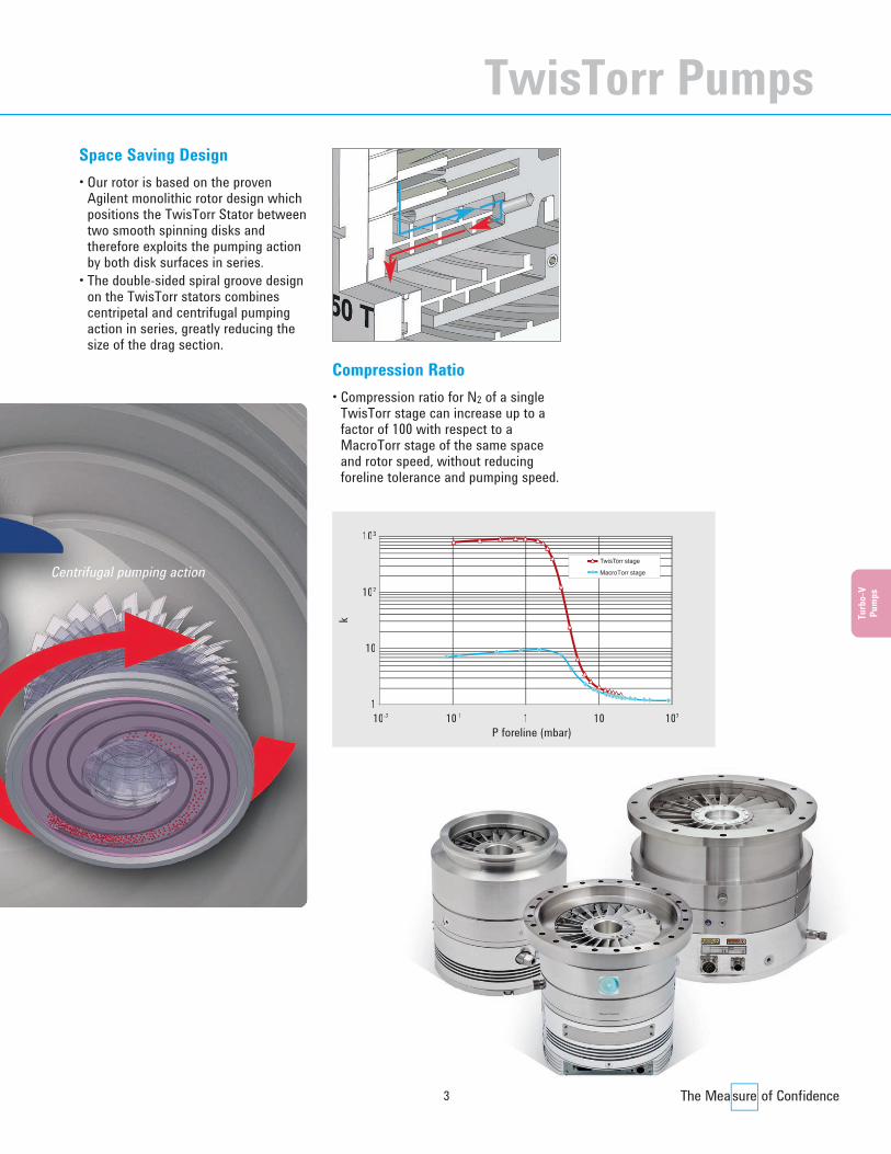
Agilent Turbo-V 2300 TwisTorr
Leading Edge Performance• The new Turbo-V 2300 TwisTorr
offers the highest pumping speed inits class for N2.
• State of the art TwisTorr technologyalso creates higher compressionratios for light gases than other largeTurbo Molecular Pumps.
• The Turbo-V 2300 TwisTorr isdesigned for scientific and researchapplications and is operated with adedicated full display rack controller.
• TwisTorr allows for very high forelinepressure tolerance, so the pump maybe backed by a smaller, cost-effectivedry scroll pump like our TS600.
Dedicated UHV Solution• The new high performing TwisTorr
drag stages allow for a 20% reductionin the height and weight of the rotor.
• High foreline pressure tolerancepermits the use of a more compactdry fore pump, allowing you todownsize your system and run a fullyUHV-compatible solution.
• Rack electronics are ideally suited forresearch and laboratory environments,and because no electronics arepresent inside the pump, provide anexcellent solution for radioactiveapplications as well.
Advanced Electronics • The Turbo-V 2300 solution is
comprised of a stand-alone pump anda rack type display controller unit,available in two voltage versions: 110 and 220 VAC.
• Remote control is available throughLogical I/O and serial (RS232)connection. Profibus solutions areavailable on request as well.
• The integrated Purge/Vent deviceallows for a controlled pump slowdown, with a modulated ventprocedure in combination with theStop Speed Reading (SSR) function.The embedded purge gas solutionprotects bearings against dust andcorrosive gases.
TwisTorr Pumps
Turbo CD2011.qxd:05 Turbo 13-06-2011 18:28 Pagina 5
6
Agilent TwisTorr Pump Models
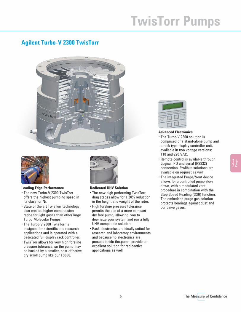
Agilent Turbo-V 750 TwisTorr System
Technical SpecificationsVacuum PerformancesPumping speed for N2 (*) N2 = 700 l/sPumping speed for Ar (*) Ar = 680 l/sPumping speed for He (*) He = 680 l/sPumping speed for H2 (*) H2 = 580 l/sCompression ratio for N2 N2 = 1 x 10¹¹
Compression ratio for Ar Ar > 1 x 10¹¹
Compression ratio for He He = 2 x 10⁸
Compression ratio for H2 H2 = 2.5 x 10⁶
Base pressure* <1 x 10⁻¹⁰ mbar(with minimum recommended forepump)Max foreline pressure for N2 6 mbarInlet Flange size ISO 160K, CFF 8”, ISO 160FForeline flange KF25
OtherRotational speed Selectable from 350 Hz to 825 HzStart up time (90% of full speed) < 3 minRecommended forepump PTS300, DS302Operational position AnyCooling options Forced Air (up to 35 °C ambient temp.)
Water (corrosion resistant loop)Max flange temperature 120°C (CFF), 80°C (ISO)during bake-out (no gas flow)Noise level FAN off < 52 dB(A) at 1 meter(pump at full speed, no load) FAN on < 55 dB(A) at 1 meterStorage temperature -20 °C to +70 °CCertifications CE, C_CSA_US, ROHS compliantPurge and Vent Standard Purge & Vent ports
Automated Purge/Vent device (accessory)
Weight ISO 160 K = 15.9 kg (34.9 lbs)(with integrated controller) CF 8” = 22.5 kg (49.4 lbs)(*): According to Pneurop 5608 III, TS 300 PRIMARY PUMP, NO INLET SCREEN
Controller SpecificationsController type Fully integrated electronics Motor control mode Field Oriented Control (FOC)Input voltage 48 Vdc (± 10%)Maximum input power 450 WMaximum output power 400 W (pump ramp-up)
300 W (water cooling)200 W (forced air cooling)
Input voltage for power supply 100 – 240 Vac (± 10%)Input frequency for power supply 50 – 60 HzMaximum input power 550 VAfor power supplyMaximum operating power 450 Wfor power supplyInterface Navigator standard remote I/O
RS 232, RS 485 serialCan accept Profibus external device
Protection category IP 54Data Logger StandardStop speed reading StandardAutomated Purge/ StandardVent device controlLeak Detector Mode function Standard
Dimensions: millimeters (inches)
Model Inlet Flange A B C9698813 ISO 160K 253.8 (9.99) Ø 179,9 (7.08) KF 259698814 CFF 8” 264.2 (10.40) Ø 202,4 (7.97) KF 259698818 ISO 160F 262.7 (10.34) Ø 225 (8.86) KF 25
Turbo CD2011.qxd:05 Turbo 13-06-2011 18:29 Pagina 6

7
Ordering InformationPumping Systems* Part NumberAgilent Turbo-V 750 ISO 160K On-Board 9698813Agilent Turbo-V 750 CFF 8” On-Board 9698814 Agilent Turbo-V 750 ISO 160F On-Board 9698818 (*): Pumping Systems include pump with integrated controller 48 Vdc, inlet screen,
9 and 15 pin mating connectors IP-54.
AccessoriesTurbo-V 750/850 TwisTorr Power Supply (5 m pump cable)* 9696521 Mains cable NEMA Plug, 3 m long 9699958 Mains cable European Plug, 3 m long 9699957 Turbo-V 750/850 TwisTorr Purge/Vent Device N.C. (0.2 m cable) 9696502 Turbo-V 750/850 TwisTorr Fan (0.2 m cable) 9696503 T-Plus software and serial cable 9699883 Inlet screen ISO 160 and CFF 8” 9699304 Water cooling kit (plastic model) 9699347 Water cooling kit (metallic model) 9699337 Water kit, Hose tail 1/8G 9699828 Vibration isolator, ISO 160 9699345 Vibration isolator, CF 8” 9699335 Vent flange, NW 10 KF / M8 9699108 Purge valve with KF16-M12 10 SCCM 9699239 Purge valve with 7/16-M12 10 SCCM 9699240 Purge valve KF16-M12 20 SCCM 9699241 Purge valve 7/16-M12 20 SCCM 9699242 External Profibus TMP gateway 9699261Forepump DS 302, with 1 ph., universal motor 9499325 TriScroll Dry Vacuum Pump PTS 300 single phase, US cord PTS03001UNIVTriScroll Dry Vacuum Pump PTS 300 single phase, Euro cord PTS03001UNIVEUTriScroll Dry Vacuum Pump PTS 300 single phase, UK cord PTS03001UNIVUKTriScroll Dry Vacuum Pump PTS 300 3 phase PTS03003UNIV(*) Power Supply is necessary to provide 48 VDC to the on board electronics.
Inlet pressure (mbar)100
100200300400500600700800
-10 10-8 10-7 10-3 1
Pum
ping
spee
d (l/
s)
1010-9 10-6 10-5 10-4 10-2 -1
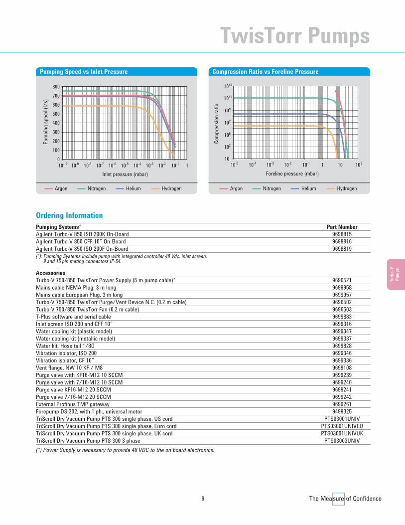
Pumping Speed vs Inlet Pressure
Foreline pressure (mbar)10
103
105
107
109
1011
1013
10-5 10-3 1
Com
pres
sion
ratio
1010-4 10-2 10-1 10 2
Compression Ratio vs Foreline Pressure
Nitrogen Helium HydrogenArgonNitrogen Helium HydrogenArgon
Turb
o-V
Pum
ps
TwisTorr Pumps
Turbo CD2011.qxd:05 Turbo 13-06-2011 18:29 Pagina 7
8
Agilent TwisTorr Pump Models
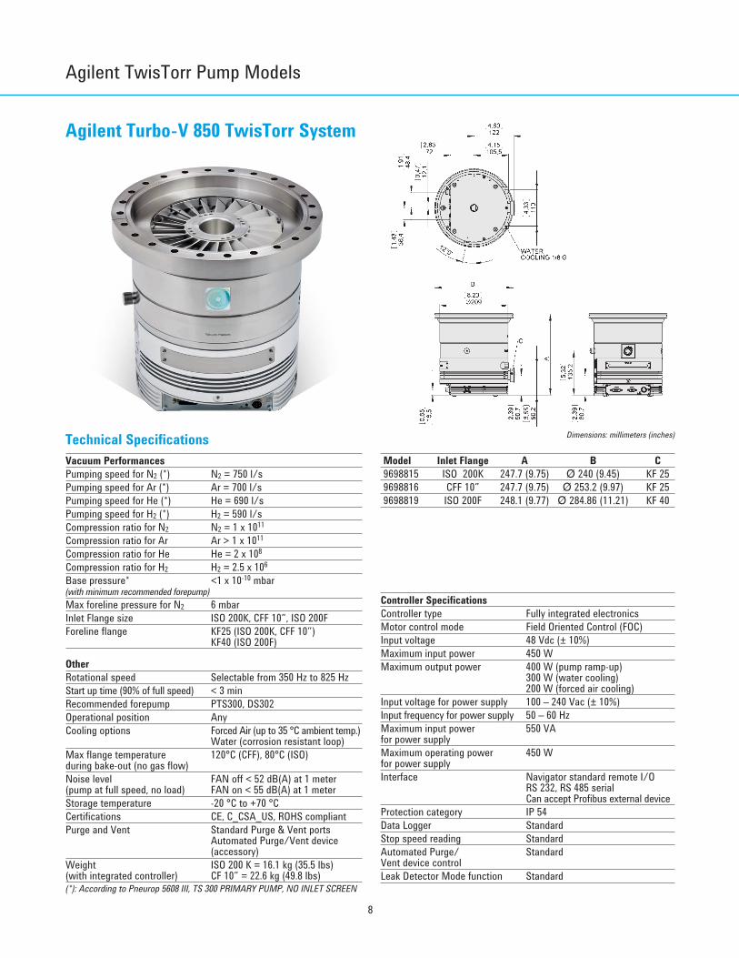
Agilent Turbo-V 850 TwisTorr System
Technical SpecificationsVacuum PerformancesPumping speed for N2 (*) N2 = 750 l/sPumping speed for Ar (*) Ar = 700 l/sPumping speed for He (*) He = 690 l/sPumping speed for H2 (*) H2 = 590 l/sCompression ratio for N2 N2 = 1 x 10¹¹
Compression ratio for Ar Ar > 1 x 10¹¹
Compression ratio for He He = 2 x 10⁸
Compression ratio for H2 H2 = 2.5 x 10⁶
Base pressure* <1 x 10⁻¹⁰ mbar(with minimum recommended forepump)Max foreline pressure for N2 6 mbarInlet Flange size ISO 200K, CFF 10”, ISO 200FForeline flange KF25 (ISO 200K, CFF 10”)
KF40 (ISO 200F)
OtherRotational speed Selectable from 350 Hz to 825 HzStart up time (90% of full speed) < 3 minRecommended forepump PTS300, DS302Operational position AnyCooling options Forced Air (up to 35 °C ambient temp.)
Water (corrosion resistant loop)Max flange temperature 120°C (CFF), 80°C (ISO)during bake-out (no gas flow)Noise level FAN off < 52 dB(A) at 1 meter(pump at full speed, no load) FAN on < 55 dB(A) at 1 meterStorage temperature -20 °C to +70 °CCertifications CE, C_CSA_US, ROHS compliantPurge and Vent Standard Purge & Vent ports
Automated Purge/Vent device (accessory)
Weight ISO 200 K = 16.1 kg (35.5 lbs)(with integrated controller) CF 10” = 22.6 kg (49.8 lbs)(*): According to Pneurop 5608 III, TS 300 PRIMARY PUMP, NO INLET SCREEN
Controller SpecificationsController type Fully integrated electronics Motor control mode Field Oriented Control (FOC)Input voltage 48 Vdc (± 10%)Maximum input power 450 WMaximum output power 400 W (pump ramp-up)
300 W (water cooling)200 W (forced air cooling)
Input voltage for power supply 100 – 240 Vac (± 10%)Input frequency for power supply 50 – 60 HzMaximum input power 550 VAfor power supplyMaximum operating power 450 Wfor power supplyInterface Navigator standard remote I/O
RS 232, RS 485 serialCan accept Profibus external device
Protection category IP 54Data Logger StandardStop speed reading StandardAutomated Purge/ StandardVent device controlLeak Detector Mode function Standard
Dimensions: millimeters (inches)
Model Inlet Flange A B C9698815 ISO 200K 247.7 (9.75) Ø 240 (9.45) KF 259698816 CFF 10” 247.7 (9.75) Ø 253.2 (9.97) KF 259698819 ISO 200F 248.1 (9.77) Ø 284.86 (11.21) KF 40
Turbo CD2011.qxd:05 Turbo 13-06-2011 18:29 Pagina 8
9
Ordering InformationPumping Systems* Part NumberAgilent Turbo-V 850 ISO 200K On-Board 9698815Agilent Turbo-V 850 CFF 10” On-Board 9698816 Agilent Turbo-V 850 ISO 200F On-Board 9698819 (*): Pumping Systems include pump with integrated controller 48 Vdc, inlet screen,
9 and 15 pin mating connectors IP-54.
AccessoriesTurbo-V 750/850 TwisTorr Power Supply (5 m pump cable)* 9696521 Mains cable NEMA Plug, 3 m long 9699958 Mains cable European Plug, 3 m long 9699957 Turbo-V 750/850 TwisTorr Purge/Vent Device N.C. (0.2 m cable) 9696502 Turbo-V 750/850 TwisTorr Fan (0.2 m cable) 9696503 T-Plus software and serial cable 9699883 Inlet screen ISO 200 and CFF 10” 9699316 Water cooling kit (plastic model) 9699347 Water cooling kit (metallic model) 9699337 Water kit, Hose tail 1/8G 9699828 Vibration isolator, ISO 200 9699346 Vibration isolator, CF 10” 9699336 Vent flange, NW 10 KF / M8 9699108 Purge valve with KF16-M12 10 SCCM 9699239 Purge valve with 7/16-M12 10 SCCM 9699240 Purge valve KF16-M12 20 SCCM 9699241 Purge valve 7/16-M12 20 SCCM 9699242 External Profibus TMP gateway 9699261Forepump DS 302, with 1 ph., universal motor 9499325 TriScroll Dry Vacuum Pump PTS 300 single phase, US cord PTS03001UNIVTriScroll Dry Vacuum Pump PTS 300 single phase, Euro cord PTS03001UNIVEUTriScroll Dry Vacuum Pump PTS 300 single phase, UK cord PTS03001UNIVUKTriScroll Dry Vacuum Pump PTS 300 3 phase PTS03003UNIV (*) Power Supply is necessary to provide 48 VDC to the on board electronics.
Inlet pressure (mbar)100
100200300400500600700800
-10 10-8 10-7 10-3 1
Pum
ping
spee
d (l/
s)
1010-9 10-6 10-5 10-4 10-2 -1
Pumping Speed vs Inlet Pressure
Foreline pressure (mbar)10
103
105
107
109
1011
1013
10-5 10-3 1
Com
pres
sion
ratio
1010-4 10-2 10-1 10 2
Compression Ratio vs Foreline Pressure
Nitrogen Helium HydrogenArgonNitrogen Helium HydrogenArgon
Turb
o-V
Pum
ps
TwisTorr Pumps
Turbo CD2011.qxd:05 Turbo 13-06-2011 18:29 Pagina 9

10
Agilent TwisTorr Pump Models
Agilent Turbo-V 750 TwisTorr Rack
Technical SpecificationsVacuum Performances ISO 160/CFF 8” CFF 6”Pumping speed for N2 (*) N2 = 700 l/s N2 = 370 l/sPumping speed for Ar (*) Ar = 680 l/s Ar = 340 l/sPumping speed for He (*) He = 680 l/s He = 500 l/sPumping speed for H2 (*) H2 = 580 l/s H2 = 470 l/sCompression ratio for N2 N2 = 1 x 10¹¹
Compression ratio for Ar Ar > 1 x 10¹¹
Compression ratio for He He = 2 x 10⁸
Compression ratio for H2 H2 = 2.5 x 10⁶
Base pressure* <1 x 10⁻¹⁰ mbar(with minimum recommended forepump)Max foreline pressure for N2 6 mbarInlet Flange size ISO 160K, CFF 8”, ISO 160FForeline flange KF25
OtherRotational speed Selectable from 350 Hz to 825 HzStart up time (90% of full speed) < 6 min (with 5 m pump cable length)Recommended forepump PTS300, DS302Operational position AnyCooling options Forced Air (up to 35 °C ambient temp.)
Water (corrosion resistant loop)Max flange temperature 120 °C (CFF), 80 °C (ISO)during bake-out (no gas flow)Noise level FAN off < 52 dB(A) at 1 meter(pump at full speed, no load) FAN on < 55 dB(A) at 1 meterStorage temperature -20 °C to +70 °CCertifications CE, C_CSA_US, ROHS compliantPurge and Vent Standard Purge & Vent ports
Automated Purge/Vent device (accessory)
Weight ISO 160 K = 15.7 kg (34.6 lbs)CF 8” = 22.3 kg (49.2 lbs)
(*): According to Pneurop 5608 III, TS 300 PRIMARY PUMP, NO INLET SCREEN
Controller SpecificationsMotor control mode Field Oriented Control (FOC)Input voltage 100 – 240 Vac (± 10%)Input frequency 50 – 60 HzMaximum input power 450 WMaximum output power 320 W (pump ramp-up)
300 W (water cooling)200 W (forced air cooling)
(Specification with standard cable length 5 mt)Interface Navigator standard remote I/O
RS 232, RS 485 serialCan accept Internal Profibus board
Protection category IP 20Data Logger StandardStop speed reading StandardActive stop StandardAutomated Purge/ StandardVent device controlExternal gauge readout 2 ports compatible with Agilent
gaugesPrimary pump control Pilot 2 external configurable relays
(48 Vdc (± 10%) - 250 mA MAX)
295.50 (11.63)
128.50 (5.06)
212.95 (8.38)
198.00 (7.80)
122.50 (4.82)
Dimensions: millimeters (inches)
Model Inlet Flange A B C9696013 ISO 160K 241.8 (9.52) Ø 179.9 (7.08) KF 259696014 CFF 8” 252.2 (9.93) Ø 202.4 (7.97) KF 259696017 CFF 6” 258.7 (10.19) Ø 151.6 (5.97) KF 259696018 ISO 160F 252.7 (9.95) Ø 225 (8.86) KF 25
Turbo CD2011.qxd:05 Turbo 13-06-2011 18:29 Pagina 10

11
Turb
o-V
Pum
ps
Ordering InformationPumps Part NumberAgilent Turbo-V 750 ISO 160K Rack 9696013 Agilent Turbo-V 750 CFF 8” Rack 9696014 Agilent Turbo-V 750 CFF 6” Rack 9696017 Agilent Turbo-V 750 ISO 160F Rack 9696018 ControllersAgilent Turbo-V 750/850-AG Rack CNT, 5 m pump cable incl. 9699525 Agilent Turbo-V 750/850-AG Rack CNT Profibus, 5 m pump cable incl. 9699526 AccessoriesMains cable NEMA Plug, 3 m long 9699958 Mains cable European Plug, 3 m long 9699957 Turbo-V 750/850 TwisTorr Purge/Vent Device N.C. (0.2 m cable) 9696502 Turbo-V 750/850 TwisTorr Fan (0.2 m cable) 9696503 Turbo-V 750/850 TwisTorr Purge/Vent 5 m extension cable 9696504 Turbo-V 750/850 TwisTorr Purge/Vent 15 m extension cable 9696505 Turbo-V 750/850 TwisTorr Purge/Vent 25 m extension cable 9696506 Turbo-V 750/850 TwisTorr Fan 5 m extension cable 9696514 Turbo-V 750/850 TwisTorr Fan 15 m extension cable 9696515 Turbo-V 750/850 TwisTorr Fan 25 m extension cable 9696516 Turbo-V 750/850 TwisTorr 10 m pump extension cable 9696518 Turbo-V 750/850 TwisTorr 20 m pump extension cable 9696519 T-Plus software and serial cable 9699883 Inlet screen ISO 160 and CFF 8” 9699304 Inlet screen CFF 6” 9699302 Water cooling kit (plastic model) 9699347 Water cooling kit (metallic model) 9699337 Water kit, Hose tail 1/8G 9699828 Vibration isolator, ISO 160 9699345 Vibration isolator, CF 6” 9699334 Vibration isolator, CF 8” 9699335 Vent flange, NW 10 KF / M8 9699108 Purge valve with KF16-M12 10 SCCM 9699239 Purge valve with 7/16-M12 10 SCCM 9699240 Purge valve KF16-M12 20 SCCM 9699241 Purge valve 7/16-M12 20 SCCM 9699242 Forepump DS 302, with 1 ph., universal motor 9499325 TriScroll Dry Vacuum Pump PTS 300 single phase, US cord PTS03001UNIVTriScroll Dry Vacuum Pump PTS 300 single phase, Euro cord PTS03001UNIVEUTriScroll Dry Vacuum Pump PTS 300 single phase, UK cord PTS03001UNIVUKTriScroll Dry Vacuum Pump PTS 300 3 phase PTS03003UNIV
Inlet pressure (mbar)100
100200300400500600700800
-10 10-8 10-7 10-3 1
Pum
ping
spee
d (l/
s)
1010-9 10-6 10-5 10-4 10-2 -1
Pumping Speed vs Inlet Pressure
Foreline pressure (mbar)10
103
105
107
109
1011
1013
10-5 10-3 1
Com
pres
sion
ratio
1010-4 10-2 10-1 10 2
Compression Ratio vs Foreline Pressure
Nitrogen Helium HydrogenArgonNitrogen Helium HydrogenArgon
TwisTorr Pumps
Turbo CD2011.qxd:05 Turbo 13-06-2011 18:29 Pagina 11
12
Agilent TwisTorr Pump Models
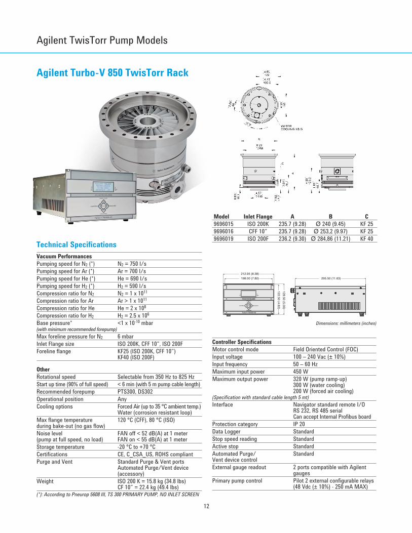
Agilent Turbo-V 850 TwisTorr Rack
Technical SpecificationsVacuum PerformancesPumping speed for N2 (*) N2 = 750 l/sPumping speed for Ar (*) Ar = 700 l/sPumping speed for He (*) He = 690 l/sPumping speed for H2 (*) H2 = 590 l/sCompression ratio for N2 N2 = 1 x 10¹¹
Compression ratio for Ar Ar > 1 x 10¹¹
Compression ratio for He He = 2 x 10⁸
Compression ratio for H2 H2 = 2.5 x 10⁶
Base pressure* <1 x 10⁻¹⁰ mbar(with minimum recommended forepump)Max foreline pressure for N2 6 mbarInlet Flange size ISO 200K, CFF 10”, ISO 200FForeline flange KF25 (ISO 200K, CFF 10”)
KF40 (ISO 200F)
OtherRotational speed Selectable from 350 Hz to 825 HzStart up time (90% of full speed) < 6 min (with 5 m pump cable length)Recommended forepump PTS300, DS302Operational position AnyCooling options Forced Air (up to 35 °C ambient temp.)
Water (corrosion resistant loop)Max flange temperature 120 °C (CFF), 80 °C (ISO)during bake-out (no gas flow)Noise level FAN off < 52 dB(A) at 1 meter(pump at full speed, no load) FAN on < 55 dB(A) at 1 meterStorage temperature -20 °C to +70 °CCertifications CE, C_CSA_US, ROHS compliantPurge and Vent Standard Purge & Vent ports
Automated Purge/Vent device (accessory)
Weight ISO 200 K = 15.8 kg (34.8 lbs)CF 10” = 22.4 kg (49.4 lbs)
(*): According to Pneurop 5608 III, TS 300 PRIMARY PUMP, NO INLET SCREEN
Controller SpecificationsMotor control mode Field Oriented Control (FOC)Input voltage 100 – 240 Vac (± 10%)Input frequency 50 – 60 HzMaximum input power 450 WMaximum output power 320 W (pump ramp-up)
300 W (water cooling)200 W (forced air cooling)
(Specification with standard cable length 5 mt)Interface Navigator standard remote I/O
RS 232, RS 485 serialCan accept Internal Profibus board
Protection category IP 20Data Logger StandardStop speed reading StandardActive stop StandardAutomated Purge/ StandardVent device controlExternal gauge readout 2 ports compatible with Agilent
gaugesPrimary pump control Pilot 2 external configurable relays
(48 Vdc (± 10%) - 250 mA MAX)
Dimensions: millimeters (inches)
Model Inlet Flange A B C9696015 ISO 200K 235.7 (9.28) Ø 240 (9.45) KF 259696016 CFF 10” 235.7 (9.28) Ø 253,2 (9.97) KF 259696019 ISO 200F 236.2 (9.30) Ø 284,86 (11.21) KF 40
295.50 (11.63)
128.50 (5.06)
212.95 (8.38)
198.00 (7.80)
122.50 (4.82)
Turbo CD2011.qxd:05 Turbo 13-06-2011 18:30 Pagina 12

13
Turb
o-V
Pum
ps
Ordering InformationPumps Part NumberAgilent Turbo-V 850 ISO 200K Rack 9696015 Agilent Turbo-V 850 CFF10” Rack 9696016 Agilent Turbo-V 850 ISO 200F Rack 9696019 ControllersAgilent Turbo-V 750/850-AG Rack CNT, 5 m pump cable incl. 9699525 Agilent Turbo-V 750/850-AG Rack CNT Profibus, 5 m pump cable incl. 9699526 AccessoriesMains cable NEMA Plug, 3 m long 9699958 Mains cable European Plug, 3 m long 9699957 Turbo-V 750/850 TwisTorr Purge/Vent Device N.C. (0.2 m cable) 9696502 Turbo-V 750/850 TwisTorr Fan (0.2 m cable) 9696503 Turbo-V 750/850 TwisTorr Purge/Vent 5 m extension cable 9696504 Turbo-V 750/850 TwisTorr Purge/Vent 15 m extension cable 9696505 Turbo-V 750/850 TwisTorr Purge/Vent 25 m extension cable 9696506 Turbo-V 750/850 TwisTorr Fan 5 m extension cable 9696514 Turbo-V 750/850 TwisTorr Fan 15 m extension cable 9696515 Turbo-V 750/850 TwisTorr Fan 25 m extension cable 9696516 Turbo-V 750/850 TwisTorr 10 m pump extension cable 9696518 Turbo-V 750/850 TwisTorr 20 m pump extension cable 9696519 T-Plus software and serial cable 9699883 Inlet screen ISO 200 and CFF 10” 9699316 Water cooling kit (plastic model) 9699347 Water cooling kit (metallic model) 9699337 Water kit, Hose tail 1/8G 9699828 Vibration isolator, ISO 200 9699346 Vibration isolator, CF 10” 9699336 Vent flange, NW 10 KF / M8 9699108 Purge valve with KF16-M12 10 SCCM 9699239 Purge valve with 7/16-M12 10 SCCM 9699240 Purge valve KF16-M12 20 SCCM 9699241 Purge valve 7/16-M12 20 SCCM 9699242 Forepump DS 302, with 1 ph., universal motor 9499325 TriScroll Dry Vacuum Pump PTS 300 single phase, US cord PTS03001UNIVTriScroll Dry Vacuum Pump PTS 300 single phase, Euro cord PTS03001UNIVEUTriScroll Dry Vacuum Pump PTS 300 single phase, UK cord PTS03001UNIVUKTriScroll Dry Vacuum Pump PTS 300 3 phase PTS03003UNIV
Inlet pressure (mbar)100
100200300400500600700800
-10 10-8 10-7 10-3 1
Pum
ping
spee
d (l/
s)
1010-9 10-6 10-5 10-4 10-2 -1
Pumping Speed vs Inlet Pressure
Foreline pressure (mbar)10
103
105
107
109
1011
1013
10-5 10-3 1
Com
pres
sion
ratio
1010-4 10-2 10-1 10 2
Compression Ratio vs Foreline Pressure
Nitrogen Helium HydrogenArgonNitrogen Helium HydrogenArgon
TwisTorr Pumps
Turbo CD2011.qxd:05 Turbo 13-06-2011 18:30 Pagina 13
14
Agilent TwisTorr Pump Models
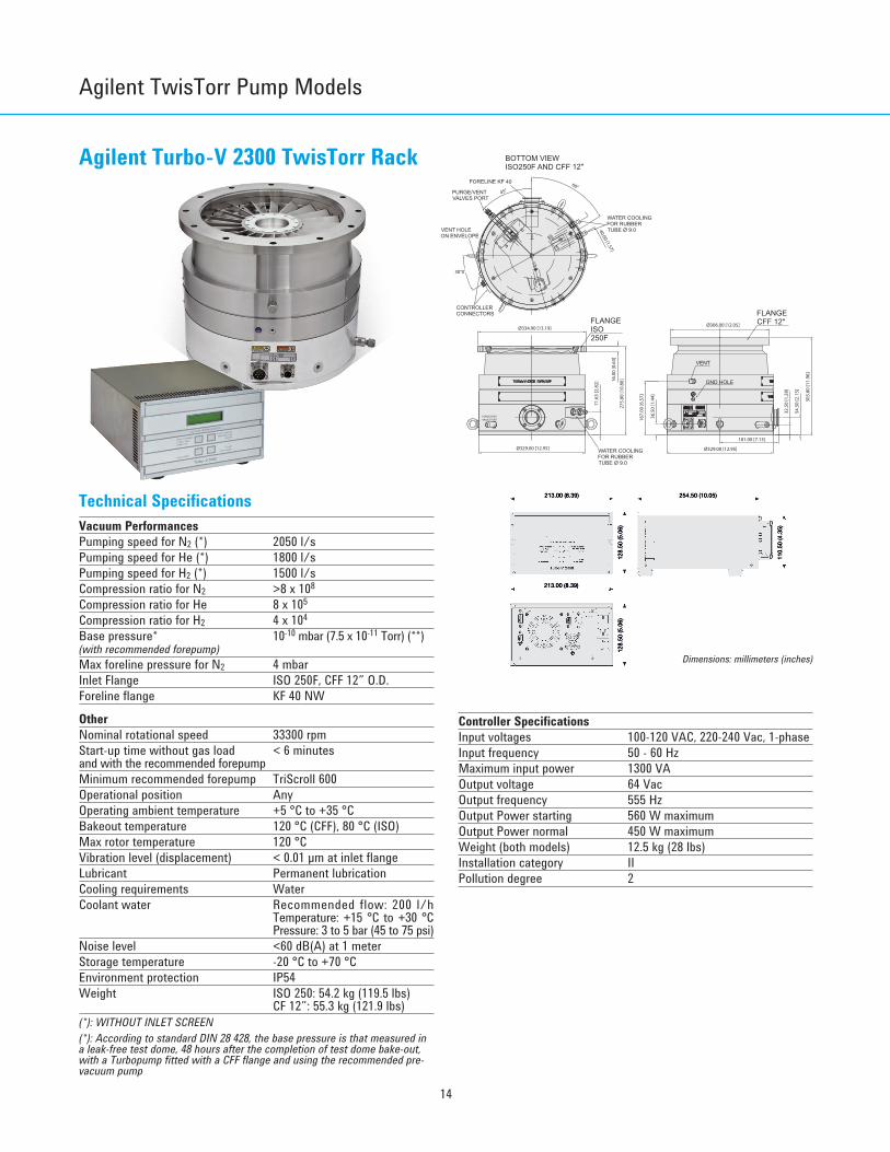
Agilent Turbo-V 2300 TwisTorr Rack
Technical SpecificationsVacuum PerformancesPumping speed for N2 (*) 2050 l/sPumping speed for He (*) 1800 l/sPumping speed for H2 (*) 1500 l/sCompression ratio for N2 >8 x 10⁸
Compression ratio for He 8 x 10⁵
Compression ratio for H2 4 x 10⁴
Base pressure* 10-10 mbar (7.5 x 10⁻¹¹ Torr) (**)(with recommended forepump)Max foreline pressure for N2 4 mbarInlet Flange ISO 250F, CFF 12” O.D.Foreline flange KF 40 NW
OtherNominal rotational speed 33300 rpmStart-up time without gas load < 6 minutesand with the recommended forepumpMinimum recommended forepump TriScroll 600Operational position AnyOperating ambient temperature +5 °C to +35 °CBakeout temperature 120 °C (CFF), 80 °C (ISO)Max rotor temperature 120 °CVibration level (displacement) < 0.01 µm at inlet flangeLubricant Permanent lubricationCooling requirements WaterCoolant water Recommended flow: 200 l/h
Temperature: +15 °C to +30 °CPressure: 3 to 5 bar (45 to 75 psi)
Noise level <60 dB(A) at 1 meterStorage temperature -20 °C to +70 °CEnvironment protection IP54Weight ISO 250: 54.2 kg (119.5 lbs)
CF 12”: 55.3 kg (121.9 lbs)(*): WITHOUT INLET SCREEN(*): According to standard DIN 28 428, the base pressure is that measured ina leak-free test dome, 48 hours after the completion of test dome bake-out,with a Turbopump fitted with a CFF flange and using the recommended pre-vacuum pump
Controller SpecificationsInput voltages 100-120 VAC, 220-240 Vac, 1-phaseInput frequency 50 - 60 HzMaximum input power 1300 VA Output voltage 64 VacOutput frequency 555 HzOutput Power starting 560 W maximumOutput Power normal 450 W maximumWeight (both models) 12.5 kg (28 lbs)Installation category IIPollution degree 2
Ø306.00 [12.05]
181.00 [7.13]
303.
80 [1
1.96
]
36.5
0 [1
.44]
54.5
0 [2
.15]
32.5
0 [1
.28]
275.
80 [1
0.86
]
Ø334.90 [13.19]
71.6
3 [2
.82]
CONTROLLERCONNECTORS FLANGE
CFF 12"FLANGE ISO 250F
WATER COOLING FOR RUBBER TUBE Ø 9.0
45°60°
PURGE/VENTVALVES PORT
VENT HOLE ON ENVELOPE
FORELINE KF 40
BOTTOM VIEW ISO250F AND CFF 12"
40.00 [1.57]
16.0
0 [0
.63]
WATER COOLING FOR RUBBER TUBE Ø 9.0
PURGE/VENTVALVES PORT
Ø329.00 [12.95] Ø329.00 [12.95]
VENT
167.
00 [6
.57]
30°0'
PURGE
VENT
GND HOLE
213.00 (8.39)
213.00 (8.39) 254.50 (10.05)
128.
50 (5
.06)
128.
50 (5
.06)
110.
50 (4
.35)
213.00 (8.39)
213.00 (8.39) 254.50 (10.05)
128.
50 (5
.06)
128.
50 (5
.06)
110.
50 (4
.35)
Dimensions: millimeters (inches)
Turbo CD2011.qxd:05 Turbo 13-06-2011 18:30 Pagina 14
15
Turb
o-V
Pum
ps
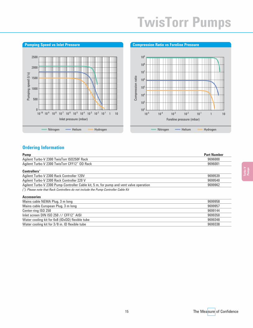
Ordering InformationPump Part NumberAgilent Turbo-V 2300 TwisTorr ISO250F Rack 9696000 Agilent Turbo-V 2300 TwisTorr CFF12” OD Rack 9696001
Controllers*Agilent Turbo-V 2300 Rack Controller 120V 9699539 Agilent Turbo-V 2300 Rack Controller 220 V 9699540 Agilent Turbo-V 2300 Pump-Controller Cable kit, 5 m, for pump and vent valve operation 9699962(*): Please note that Rack Controllers do not include the Pump-Controller Cable Kit
AccessoriesMains cable NEMA Plug, 3 m long 9699958Mains cable European Plug, 3 m long 9699957Center-ring ISO 250 9699144Inlet screen DIN ISO 250 // CFF12” AISI 9699350Water cooling kit for 6x8 (IDxOD) flexible tube 9699348Water cooling kit for 3/8 in. ID flexible tube 9699338
Inlet pressure (mbar)10
0
500
1000
1500
2000
2500
-10 10-8 1
Pum
ping
spee
d (l/
s)
10-9 10-7 10-6 10-210-310-5 10-4 10-1 10
Pumping Speed vs Inlet Pressure
Foreline pressure (mbar)10
103
102
104
105
106
107
108
109
-5 10-3 1
Com
pres
sion
ratio
10-4 10-2 10-1 10
Compression Ratio vs Foreline Pressure
Nitrogen Helium HydrogenNitrogen Helium Hydrogen
TwisTorr Pumps
Turbo CD2011.qxd:05 Turbo 13-06-2011 18:30 Pagina 15
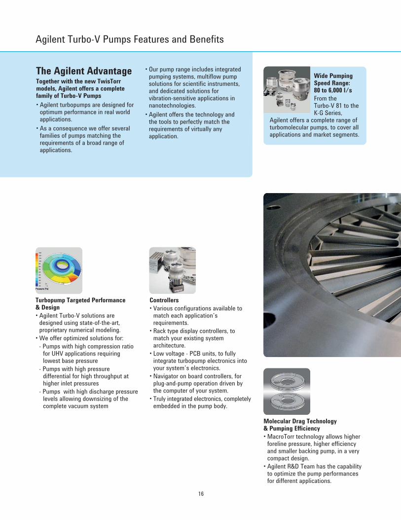
The Agilent AdvantageTogether with the new TwisTorrmodels, Agilent offers a completefamily of Turbo-V Pumps• Agilent turbopumps are designed for
optimum performance in real worldapplications.
• As a consequence we offer severalfamilies of pumps matching therequirements of a broad range ofapplications.
• Our pump range includes integratedpumping systems, multiflow pumpsolutions for scientific instruments,and dedicated solutions forvibration-sensitive applications innanotechnologies.
• Agilent offers the technology andthe tools to perfectly match therequirements of virtually anyapplication.
16
Agilent Turbo-V Pumps Features and Benefits
Controllers• Various configurations available to
match each application’srequirements.
• Rack type display controllers, tomatch your existing systemarchitecture.
• Low voltage - PCB units, to fullyintegrate turbopump electronics intoyour system’s electronics.
• Navigator on board controllers, forplug-and-pump operation driven bythe computer of your system.
• Truly integrated electronics, completelyembedded in the pump body.
Turbopump Targeted Performance & Design• Agilent Turbo-V solutions are
designed using state-of-the-art,proprietary numerical modeling.
• We offer optimized solutions for:- Pumps with high compression ratio
for UHV applications requiringlowest base pressure
- Pumps with high pressuredifferential for high throughput athigher inlet pressures
- Pumps with high discharge pressurelevels allowing downsizing of thecomplete vacuum system
Molecular Drag Technology & Pumping Efficiency• MacroTorr technology allows higher
foreline pressure, higher efficiencyand smaller backing pump, in a verycompact design.
• Agilent R&D Team has the capabilityto optimize the pump performancesfor different applications.
Wide PumpingSpeed Range:80 to 6,000 l/sFrom the Turbo-V 81 to theK-G Series,
Agilent offers a complete range ofturbomolecular pumps, to cover allapplications and market segments.
Turbo CD2011.qxd:05 Turbo 13-06-2011 18:30 Pagina 16
17
Turb
o-V
Pum
ps
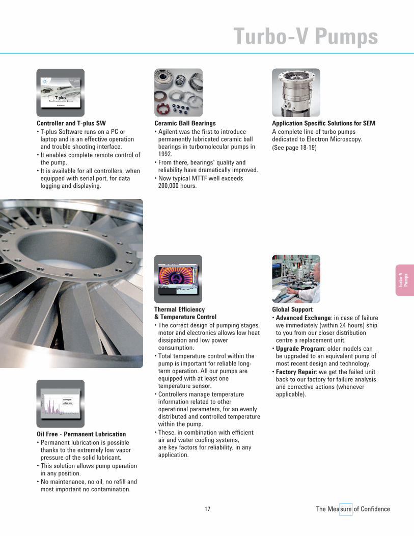
Ceramic Ball Bearings• Agilent was the first to introduce
permanently lubricated ceramic ballbearings in turbomolecular pumps in1992.
• From there, bearings' quality andreliability have dramatically improved.
• Now typical MTTF well exceeds200,000 hours.
Application Specific Solutions for SEMA complete line of turbo pumpsdedicated to Electron Microscopy.(See page 18-19)
Global Support• Advanced Exchange: in case of failure
we immediately (within 24 hours) shipto you from our closer distributioncentre a replacement unit.
• Upgrade Program: older models canbe upgraded to an equivalent pump ofmost recent design and technology.
• Factory Repair: we get the failed unitback to our factory for failure analysisand corrective actions (wheneverapplicable).
Thermal Efficiency & Temperature Control• The correct design of pumping stages,
motor and electronics allows low heatdissipation and low powerconsumption.
• Total temperature control within thepump is important for reliable long-term operation. All our pumps areequipped with at least onetemperature sensor.
• Controllers manage temperatureinformation related to otheroperational parameters, for an evenlydistributed and controlled temperaturewithin the pump.
• These, in combination with efficientair and water cooling systems, are key factors for reliability, in anyapplication.
Oil Free - Permanent Lubrication• Permanent lubrication is possible
thanks to the extremely low vaporpressure of the solid lubricant.
• This solution allows pump operationin any position.
• No maintenance, no oil, no refill andmost important no contamination.
Controller and T-plus SW• T-plus Software runs on a PC or
laptop and is an effective operationand trouble shooting interface.
• It enables complete remote control ofthe pump.
• It is available for all controllers, whenequipped with serial port, for datalogging and displaying.
Turbo-V Pumps
Turbo CD2011.qxd:05 Turbo 13-06-2011 18:30 Pagina 17

18
Agilent Turbo-V SEM Features and Benefits
The AgilentAdvantage: Dedicated Solutions for SEM ApplicationsAs the leading Ultra-High Vacuumproducts supplier, AgilentTechnologies has long been workingwith all SEM and TEMmanufacturers, providing applicationspecific solutions.Today Agilent is the only companyable to offer a complete anddedicated range of SEM products,including primary pumps,turbomolecular pumps, ion getterpumps, and vacuum measurement,that meet the most stringentrequirements of the industry.
Turbo-V SEM versions are availableon request; please ask Agilent fortechnical details.
Carl Zeiss SMT, global leader in light,electron and ion-optical technologiesfor industry and R&D, has designated Agilent Technologies as a Carl ZeissSMT Supply Chain Partner.
Wide, Dedicated RangeSizes: 80, 300, 400, 550, 700, 1000 l/s,from NW63 to ISO 250 flanges: the right size for each application, at the right cost.
Dry Lubrication• Oil free, no need for refill.• Contamination free.• Mountable in any position.• No preventive maintenance.
Foreline Pressure up to 15 mbar• Ideal to minimize forepump size (i.e.
IDP-2 and IDP-3 Dry Scroll Pumps),resulting in the lowest cost ofownership.
• Vacuum in the gun and sample chamber must be particle-free andoil-free
• No Vibrations• No Resonances• No Magnetic stray fields from both IGP and TMPs • No Electric noise from power supplies• Fastest Pumpdown cycles• Pressure levels stable and controlled• Maximum Uptime• Fast, worldwide Service Support
Vacuum for SEM: basic requirements
Supply Chain PartnerCarl Zeiss SMT AG
Turbo CD2011.qxd:05 Turbo 13-06-2011 18:30 Pagina 18

19
Turb
o-V
Pum
ps
Monolithic RotorMounting in any position, with nolimitations.• Rugged design.• Light weight.• Air inrush proof.• Earthquake proof.
Magnets Free Design• Lowest Magnetic Signature in the
industry.• Best to work very close to ebeams.• No need for magnetic shields.
Superior Vibration Isolation System• Lower vibrations than Mag-Lev!• Certified Computer Aided Balancing,
thanks to suspended benches withspecial high sensitivityaccelerometers.
Improved Roto Dynamics• Designed to avoid internal mechanical
resonances.• Agilent SEM turbopumps are designed
to minimize vibration sources, andhave a very stable vibration profile.
Integrated Double Dampers• Agilent developed special Integrated
Double Dampers for the mostdemanding SEM applications.
• Damping factor up to 1400X (Radial, at unbalance level, with IDD100 ISOK):better than Mag-Lev!
• Best SEM image resolution.
Enhanced Electronic Controllers• Universal voltages.• Integrated Vent valve command,
adjustable valve delay and openingtime.
• Pressure gauge reading.• Integrated Profibus.
Turbo-V Pumps
Turbo CD2011.qxd:05 Turbo 13-06-2011 18:30 Pagina 19
20
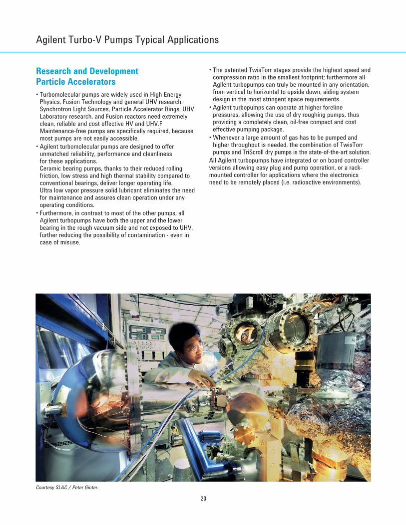
Research and DevelopmentParticle Accelerators• Turbomolecular pumps are widely used in High Energy
Physics, Fusion Technology and general UHV research.Synchrotron Light Sources, Particle Accelerator Rings, UHVLaboratory research, and Fusion reactors need extremelyclean, reliable and cost effective HV and UHV.FMaintenance-free pumps are specifically required, becausemost pumps are not easily accessible.
• Agilent turbomolecular pumps are designed to offerunmatched reliability, performance and cleanliness for these applications.Ceramic bearing pumps, thanks to their reduced rollingfriction, low stress and high thermal stability compared toconventional bearings, deliver longer operating life.Ultra low vapor pressure solid lubricant eliminates the needfor maintenance and assures clean operation under anyoperating conditions.
• Furthermore, in contrast to most of the other pumps, allAgilent turbopumps have both the upper and the lowerbearing in the rough vacuum side and not exposed to UHV,further reducing the possibility of contamination - even incase of misuse.
• The patented TwisTorr stages provide the highest speed andcompression ratio in the smallest footprint; furthermore allAgilent turbopumps can truly be mounted in any orientation,from vertical to horizontal to upside down, aiding systemdesign in the most stringent space requirements.
• Agilent turbopumps can operate at higher forelinepressures, allowing the use of dry roughing pumps, thusproviding a completely clean, oil-free compact and costeffective pumping package.
• Whenever a large amount of gas has to be pumped andhigher throughput is needed, the combination of TwisTorrpumps and TriScroll dry pumps is the state-of-the-art solution.
All Agilent turbopumps have integrated or on board controllerversions allowing easy plug and pump operation, or a rack-mounted controller for applications where the electronicsneed to be remotely placed (i.e. radioactive environments).
Courtesy SLAC / Peter Ginter.
Agilent Turbo-V Pumps Typical Applications
Turbo CD2011.qxd:05 Turbo 13-06-2011 18:30 Pagina 20

21
Turb
o-V
Pum
ps
NanotechnologiesElectron Microscopy (SEM, TEM), Focused Ion-beamSystems (FIB) and Surface Analysis• Modern focused-beam systems such as SEM’s, TEM’s and
FIB’s utilize columns that project electrons or ions ontomicroscopic samples for detailed analysis. End usersanalyze all types of substances from organic compounds tosemiconductor wafers. In the Semiconductor industry, inparticular, they require more sensitivity for better sampleresolution. Another key requirement is high samplethroughput in order to lower the cost of ownership of theseinstruments.
• Based on these requirements, the demand for highperformance vacuum pumps is greater than ever. Agilentoffers a full range of high and ultra-high vacuum pumpsdesigned especially for the demanding requirements ofSEM’s, TEM’s and surface analysis systems (Agilent has afull range of ion pumps, which are key products for thisapplication; please see ion pump section).
• Turbo molecular pumps are also a key component in modernfocused-beam systems because they offer fast, oil-free air evacuation of large sample chambers (oil-freeoperation is a key requirement of many modern analysisapplications such as semiconductor manufacturing). From Agilent’s full range of turbo pumps, the focused-beamsystem designer can choose a pump size that offers the bestchamber evacuation time with the best cost of ownershipand compact size for use in limited space situations.
• Agilent has a full line of customized, low vibration turbopumps for the most sensitive microscopy applications.Finally, Agilent has a full range of integrated pumpcontrollers that offer the highest control flexibility with nearzero electromagnetic noise generation.
• Agilent offers a full range of application specific designedSEM turbo pumps including 80 l/s, 300 l/s, 550 l/s, 700 l/s and 1000 l/s speeds. All of Agilent’s SEM turbo pumps designs can be verified inAgilent’s application lab. Finally, each SEM turbo pump istested in production before being shipped to the customer.
Courtesy TRIUMF-ISAC.
Turbo-V Pumps
Turbo CD2011.qxd:05 Turbo 13-06-2011 18:30 Pagina 21
22
Agilent Turbo-V Pumps Typical Applications
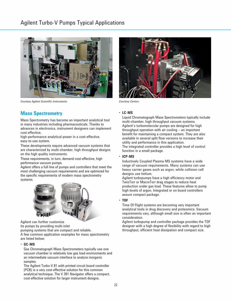
Mass SpectrometryMass Spectrometry has become an important analytical toolin many industries including pharmaceuticals. Thanks toadvances in electronics, instrument designers can implementcost-effective, high-performance analytical power in a cost-effective, easy-to-use system.These developments require advanced vacuum systems thatare characterized by multi-chamber, high throughput designson the high quality instruments.These requirements, in turn, demand cost-effective, highperformance vacuum pumps.Agilent offers a full line of pumps and controllers that meet themost challenging vacuum requirements and are optimized forthe specific requirements of modern mass spectrometrysystems.
Agilent can further customize its pumps by providing multi-inlet pumping systems that are compact and reliable. A few common application examples for mass spectrometry are listed below:• GC-MS
Gas Chromatograph Mass Spectrometers typically use onevacuum chamber in relatively low gas load environments andan intermediate vacuum interface to analyze inorganicsamples. The Agilent Turbo-V 81 with printed circuit board controller(PCB) is a very cost-effective solution for this commonanalytical technique. The V 301 Navigator offers a compact,cost-effective solution for larger instrument designs.
• LC-MSLiquid Chromatograph Mass Spectrometers typically includemulti-chamber, high throughput vacuum systems. Agilent’s turbomolecular pumps are designed for highthroughput operation with air cooling – an importantbenefit for maintaining a compact system. They are alsoavailable in several split flow versions to increase theirutility and performance in this application. The integrated controller provides a high level of controlfunction in a small package.
• ICP-MSInductively Coupled Plasma-MS systems have a widerange of vacuum requirements. Many systems can useheavy carrier gases such as argon, while collision celldesigns use helium.Agilent turbopumps have a high efficiency motor andTwisTorr or MacroTorr drag stages to reduce heatproduction under gas load. These features allow to pumphigh levels of argon. Integrated or on board controllersassure compact package.
• TOFTime Of Flight systems are becoming very importantanalytical tools in drug discovery and proteomics. Vacuumrequirements vary, although small size is often an importantconsideration. Agilent turbopump and controller package provides the TOFdesigner with a high degree of flexibility with regard to highthroughput, efficient heat dissipation and compact size.
Courtesy Agilent Scientific Instruments. Courtesy Centorr.
Turbo CD2011.qxd:05 Turbo 13-06-2011 18:30 Pagina 22
23
Turb
o-V
Pum
ps
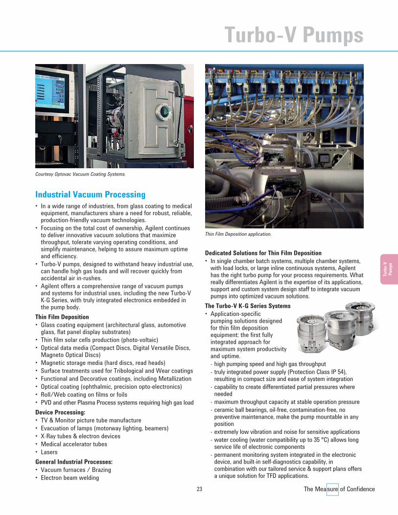
Industrial Vacuum Processing• In a wide range of industries, from glass coating to medical
equipment, manufacturers share a need for robust, reliable,production-friendly vacuum technologies.
• Focusing on the total cost of ownership, Agilent continuesto deliver innovative vacuum solutions that maximizethroughput, tolerate varying operating conditions, andsimplify maintenance, helping to assure maximum uptimeand efficiency.
• Turbo-V pumps, designed to withstand heavy industrial use,can handle high gas loads and will recover quickly fromaccidental air in-rushes.
• Agilent offers a comprehensive range of vacuum pumpsand systems for industrial uses, including the new Turbo-VK-G Series, with truly integrated electronics embedded inthe pump body.
Thin Film Deposition• Glass coating equipment (architectural glass, automotive
glass, flat panel display substrates)• Thin film solar cells production (photo-voltaic)• Optical data media (Compact Discs, Digital Versatile Discs,
Magneto Optical Discs)• Magnetic storage media (hard discs, read heads)• Surface treatments used for Tribological and Wear coatings• Functional and Decorative coatings, including Metallization• Optical coating (ophthalmic, precision opto-electronics)• Roll/Web coating on films or foils• PVD and other Plasma Process systems requiring high gas loadDevice Processing: • TV & Monitor picture tube manufacture• Evacuation of lamps (motorway lighting, beamers)• X-Ray tubes & electron devices• Medical accelerator tubes• LasersGeneral Industrial Processes:• Vacuum furnaces / Brazing• Electron beam welding
Dedicated Solutions for Thin Film Deposition• In single chamber batch systems, multiple chamber systems,
with load locks, or large inline continuous systems, Agilenthas the right turbo pump for your process requirements. Whatreally differentiates Agilent is the expertise of its applications,support and custom system design staff to integrate vacuumpumps into optimized vacuum solutions.
The Turbo-V K-G Series Systems• Application-specific
pumping solutions designed for thin film depositionequipment: the first fullyintegrated approach formaximum system productivityand uptime.- high pumping speed and high gas throughput- truly integrated power supply (Protection Class IP 54),
resulting in compact size and ease of system integration- capability to create differentiated partial pressures where
needed- maximum throughput capacity at stable operation pressure- ceramic ball bearings, oil-free, contamination-free, no
preventive maintenance, make the pump mountable in anyposition
- extremely low vibration and noise for sensitive applications- water cooling (water compatibility up to 35 °C) allows long
service life of electronic components- permanent monitoring system integrated in the electronic
device, and built-in self-diagnostics capability, incombination with our tailored service & support plans offersa unique solution for TFD applications.
Courtesy Optovac Vacuum Coating Systems.
Thin Film Deposition application.
Turbo-V Pumps
Turbo CD2011.qxd:05 Turbo 13-06-2011 18:30 Pagina 23

24
Pump Specification
Pumping Speed, l/sNitrogenHeliumHydrogenArgon
Compression RatioNitrogenHeliumHydrogenArgon
Base pressure, mbarwith recommended mechanical pumpwith recommended dry pump
Startup Time, min
Rotational Speed, rpm
Recommended ForepumpTwo-stage mechanical pumpDry pump
Inlet Flange, nominal diameterKlamp Flange, mmConFlat, mm (inches OD)ISO clamp style, mmISO-F bolted, mm
Foreline Flange, nominal diameterKlamp Flange
SEM Version Available on Request
ControllersRack ControllerNavigator on board ControllerIntegrated ElectronicsPCB Controller
Turbo-V 301 NavigatorDN 100 DN 160
250 280220 230200 210
7 x 10⁸ 7 x 10⁸
1 x 10⁵ 1 x 10⁵
1 x 10⁴ 1 x 10⁴
< 5 x 10⁻¹⁰ < 5 x 10⁻¹⁰
< 5 x 10⁻⁹ < 5 x 10⁻⁹
2.5 2.5
56,000 56,000
DS 102 DS 102SH-110 SH-110
- -100 (6) 160 (8)
100 160- -
NW16 NW16
• •
• •• •- -• •
Turbo-V 81 TDN 40 DN 63
50 7756 6546 50
7 x 10⁸ 7 x 10⁸
3 x 10³ 3 x 10³
3 x 10² 3 x 10²
5 x 10⁻⁹ 5 x 10⁻⁹
5 x 10⁻⁸ 5 x 10⁻⁸
< 1 < 1
80,000 80,000
DS 42 DS 42DS 102 DS 102SH-110 SH-110
40 -35 (2.75) 63 (4.5)
- 63- -
NW16 NW16
- -
• •• •- -• •
Turbo-V 81 MDN 40 DN 63
50 7756 6546 50
3 x 10⁸ 7 x 10⁶
8 x 10⁴ 8 x 10⁴
7 x 10³ 7 x 10³
5 x 10⁻¹⁰ 5 x 10⁻¹⁰
5 x 10⁻⁹ 5 x 10⁻⁹
< 1 < 1
80,000 80,000
DS 42 DS 42DS 102 DS 102SH-110 SH-110
40 -35 (2.75) 63 (4.5)
- 63- -
NW16 NW16
- -
• •• •- -• •
Agilent Turbo-V Pump Models
Turbo-V 6000 available on request (see page 40-41)
24
Turbo CD2011.qxd:05 Turbo 13-06-2011 18:30 Pagina 24
25
Turb
o-V
Pum
ps
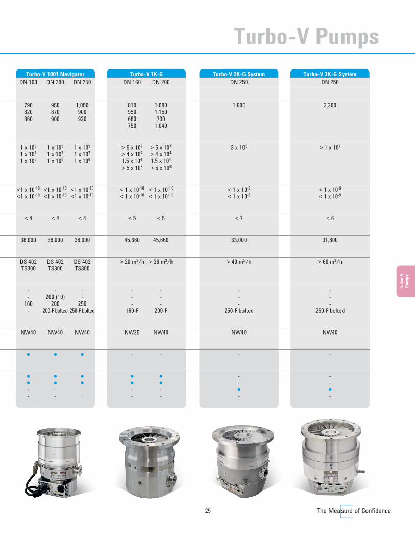
Turbo-V 1001 NavigatorDN 160 DN 200 DN 250
790 950 1,050820 870 900860 900 920
1 x 10⁹ 1 x 10⁹ 1 x 10⁹
1 x 10⁷ 1 x 10⁷ 1 x 10⁷
1 x 10⁶ 1 x 10⁶ 1 x 10⁶
<1 x 10⁻¹⁰ <1 x 10⁻¹⁰ <1 x 10⁻¹⁰
<1 x 10⁻¹⁰ <1 x 10⁻¹⁰ <1 x 10⁻¹⁰
< 4 < 4 < 4
38,000 38,000 38,000
DS 402 DS 402 DS 402TS300 TS300 TS300
- - -- 200 (10) -
160 200 250- 200-F bolted 250-F bolted
NW40 NW40 NW40
• • •
• • •• • •- - -- - -
Turbo-V 2K-G SystemDN 250
1,600
3 x 10⁵
< 1 x 10⁻⁸
< 1 x 10⁻⁸
< 7
33,000
> 40 m3/h
---
250-F bolted
NW40
-
--•-
Turbo-V 1K-GDN 160 DN 200
810 1,080950 1,150680 730750 1,040
> 5 x 10⁷ > 5 x 10⁷
> 4 x 10⁴ > 4 x 10⁴
1.5 x 10⁴ 1.5 x 10⁴
> 5 x 10⁸ > 5 x 10⁸
< 1 x 10⁻¹⁰ < 1 x 10⁻¹⁰
< 1 x 10⁻¹⁰ < 1 x 10⁻¹⁰
< 5 < 5
45,660 45,660
> 20 m3/h > 36 m3/h
- -- -- -
160-F 200-F
NW25 NW40
- -
• •• •- -- -
Turbo-V 3K-G SystemDN 250
2,200
> 1 x 10⁷
< 1 x 10⁻⁹
< 1 x 10⁻⁹
< 6
31,800
> 60 m3/h
---
250-F bolted
NW40
-
--•-
Turbo-V Pumps
25
Turbo CD2011.qxd:05 Turbo 13-06-2011 18:30 Pagina 25

Ø 69.3 (2.73)
Ø 80 (3.15) Ø 113.5 (4.47)
Ø 80 (3.15)
64.5
(2.5
4)
80.5
(3.1
7)12
(0.4
7)
144.
6 (5
.69)
17.3
(0.6
8)
161.
8 (6
.37)
Ø 80 (3.15)
Ø 94.9 (3.74) Ø 80 (3.15)
Ø 92 (3.62)
ISO 63 CFF 2.75 CFF 4.5KF 40
Ø 55 (2.17)
60.5 (2.38) 58.5 (2.13)
84 (3.31)
37.5
(1.4
8)32
(1.2
6)
163.
5 (6
.44)
25 (0
.98)
Ø 91.5 (3.60)
A
50.1
(1.9
7)25
.5 (1
.00)
144.
5 (5
.69)
17.5
(0.6
9)
VIEW FROM A
26
Agilent Turbo-V Pump Models
Dimensions: millimeters (inches)
Agilent Turbo-V 81-M
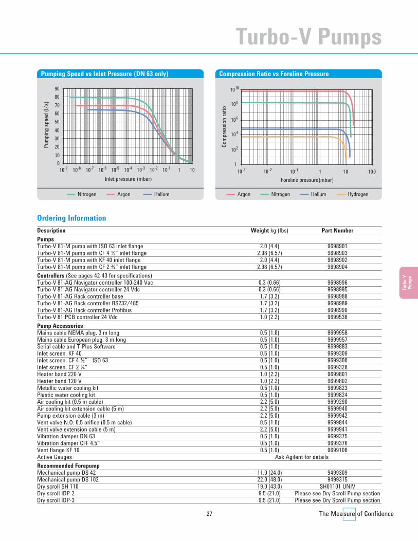
Technical SpecificationsPumping speed (l/s)With CF 4 ½” or ISO 63: N2: 77 l/s He: 65 l/s H2: 50 l/sWith CF 2 ¾” or KF 40: N2: 50 l/s He: 56 l/s H2: 46 l/sCompression ratio N2: 5 x 10⁸ He: 8 x 10⁴ H2: 7 x 10³
Base pressure* (with recommended forepump) 5 x 10⁻¹⁰ mbar (3.8 x 10⁻¹⁰ Torr)Inlet flange CF 4 ½” O.D. ISO 63
CF 2 ¾” O.D. KF 40Foreline flange KF 16 NWRotational speed 1350 Hz (max)Start-up time < 60 secondsRecommended forepump Mechanical: Agilent DS 42 – DS 102
Dry pump: Agilent IDP-2, IDP-3, SH 110Operating position AnyCooling requirements Natural air convection
Forced air or water optionalBakeout temperature 120 °C at inlet flange max. (CF flange)
80 °C at inlet flange max. (ISO flange)Vibration level (displacement) <0.01 µm at inlet flangeWeight kg (lbs) ISO 63: 2 (4.4)
CF 4 ½”: 2.98 (6.57)* According to standard DIN 28 428.NOTE • The pump is available with On-board Navigator Controller, ¼ Rack Controller or PCB Controller;
for information on controllers see also pages 32-33.
Turbo CD2011.qxd:05 Turbo 13-06-2011 18:30 Pagina 26
27
Turb
o-V
Pum
ps
Description Weight kg (Ibs) Part NumberPumpsTurbo-V 81-M pump with ISO 63 inlet flange 2.0 (4.4) 9698901Turbo-V 81-M pump with CF 4 ½” inlet flange 2.98 (6.57) 9698903 Turbo-V 81-M pump with KF 40 inlet flange 2.0 (4.4) 9698902 Turbo-V 81-M pump with CF 2 ¾” inlet flange 2.98 (6.57) 9698904 Controllers (See pages 42-43 for specifications)Turbo-V 81-AG Navigator controller 100-240 Vac 0.3 (0.66) 9698996Turbo-V 81-AG Navigator controller 24 Vdc 0.3 (0.66) 9698995Turbo-V 81-AG Rack controller base 1.7 (3.2) 9698988 Turbo-V 81-AG Rack controller RS232/485 1.7 (3.2) 9698989 Turbo-V 81-AG Rack controller Profibus 1.7 (3.2) 9698990Turbo-V 81 PCB controller 24 Vdc 1.0 (2.2) 9699538Pump AccessoriesMains cable NEMA plug, 3 m long 0.5 (1.0) 9699958Mains cable European plug, 3 m long 0.5 (1.0) 9699957Serial cable and T-Plus Software 0.5 (1.0) 9699883Inlet screen, KF 40 0.5 (1.0) 9699309Inlet screen, CF 4 ½” - ISO 63 0.5 (1.0) 9699300Inlet screen, CF 2 ¾” 0.5 (1.0) 9699328Heater band 220 V 1.0 (2.2) 9699801 Heater band 120 V 1.0 (2.2) 9699802 Metallic water cooling kit 0.5 (1.0) 9699823 Plastic water cooling kit 0.5 (1.0) 9699824 Air cooling kit (0.5 m cable) 2.2 (5.0) 9699290 Air cooling kit extension cable (5 m) 2.2 (5.0) 9699940 Pump extension cable (3 m) 2.2 (5.0) 9699942Vent valve N.O. 0.5 orifice (0.5 m cable) 0.5 (1.0) 9699844Vent valve extension cable (5 m) 2.2 (5.0) 9699941Vibration damper DN 63 0.5 (1.0) 9699375Vibration damper CFF 4.5" 0.5 (1.0) 9699376Vent flange KF 10 0.5 (1.0) 9699108Active Gauges Ask Agilent for detailsRecommended ForepumpMechanical pump DS 42 11.0 (24.0) 9499309 Mechanical pump DS 102 22.0 (48.0) 9499315 Dry scroll SH 110 19.0 (43.0) SH01101 UNIVDry scroll IDP-2 9.5 (21.0) Please see Dry Scroll Pump sectionDry scroll IDP-3 9.5 (21.0) Please see Dry Scroll Pump section
Ordering Information
Inlet pressure (mbar)
90
010-9 10-7 10-6 10-2 10
Pum
ping
spee
d (l/
s)
110-8 10-5 10-4 10-3 10-1
80706050
3040
2010
Pumping Speed vs Inlet Pressure (DN 63 only)
Foreline pressure (mbar)
110-3 10-2
Com
pres
sion
ratio
10-1 1 10
102
104
106
108
1010
100
Compression Ratio vs Foreline Pressure
Nitrogen Argon Helium Nitrogen Helium HydrogenArgon
Turbo-V Pumps
Turbo CD2011.qxd:05 Turbo 13-06-2011 18:30 Pagina 27

28
Agilent Turbo-V Pump Models
Ø 80 (3.15)
Ø 113.5 (4.47) Ø 80 (3.15)
Ø 69.3 (2.73)
64 (2
.52)
80 (3
.15)
12 (0
.47)
128.
7 (5
.07)
17.5
(0.6
9)
128.
6 (5
.06)
73 (2
.87)
Ø 80 (3.15)
Ø 94.9 (3.74) Ø 80 (3.15)
Ø 92 (3.62)ISO 63
CFF 4.5 CFF 2.75
KF 40
Ø 55 (2.17)
60.5 (2.38) 58.5 (2.13)
84 (3.31)
37.5
(1.4
8)32
(1.2
6)
147.
5 (5
.81)
25 (0
.98)
Ø 91.5 (3.60)
A
145.
8 (5
.74)
17.3
(0.6
8)
VIEW FROM A
Dimensions: millimeters (inches)
Agilent Turbo-V 81-T
Technical SpecificationsPumping speed (l/s)With CF 4 ½” or ISO 63: N2: 77 l/s He: 65 l/s H2: 50 l/sWith CF 2 ¾” or KF 40: N2: 50 l/s He: 56 l/s H2: 46 l/sCompression ratio N2: >7 x 10⁶ He: 3 x 10³ H2: 3 x 10²
Base pressure* (with recommended forepump) 5 x 10⁻⁹ mbar (3.8 x 10⁻⁹ Torr)Inlet flange CF 4 ½” O.D. ISO 63
CF 2 ¾” O.D. KF 40Foreline flange KF 16 NWRotational speed 1350 Hz (max)Start-up time < 60 secondsRecommended forepump Mechanical: Agilent DS 42 – DS 102
Dry pump: Agilent IDP-2, IDP-3, SH 110Operating position AnyCooling requirements Natural air convection
Forced air or water optionalBakeout temperature 120 °C at inlet flange max. (CF flange)
80 °C at inlet flange max. (ISO flange)Vibration level (displacement) <0.01 µm at inlet flangeWeight kg (lbs) ISO 63: 1.82 (4)
CF 4 ½”: 2,68 (5.90)* According to standard DIN 28 428.NOTE • The pump is available with On-board Navigator Controller, ¼ Rack Controller or PCB Controller;
for information on controllers see also es 32-33.
Turbo CD2011.qxd:05 Turbo 13-06-2011 18:30 Pagina 28

29
Turb
o-V
Pum
ps
Description Weight kg (Ibs) Part NumberPumpsTurbo-V 81-T pump with ISO 63 inlet flange 1.82 (4.0) 9698905Turbo-V 81-T pump with CF 4 ½” inlet flange 2.68 (5.9) 9698907 Turbo-V 81-T pump with KF 40 inlet flange 1.82 (4.0) 9698906 Turbo-V 81-T pump with CF 2 ¾” inlet flange 2.68 (5.9) 9698908 Controllers (See pages 42-43 for specifications)Turbo-V 81-AG Navigator controller 100-240 Vac 0.3 (0.66) 9698996Turbo-V 81-AG Navigator controller 24 Vdc 0.3 (0.66) 9698995Turbo-V 81-AG Rack controller base 1.7 (3.2) 9698988 Turbo-V 81-AG Rack controller RS232/485 1.7 (3.2) 9698989 Turbo-V 81-AG Rack controller Profibus 1.7 (3.2) 9698990Turbo-V 81 PCB controller 24 Vdc 1.0 (2.2) 9699538Pump AccessoriesMains cable NEMA plug, 3 m long 0.5 (1.0) 9699958Mains cable European plug, 3 m long 0.5 (1.0) 9699957Serial cable and T-Plus Software 0.5 (1.0) 9699883Inlet screen, KF 40 0.5 (1.0) 9699309Inlet screen, CF 4 ½” - ISO 63 0.5 (1.0) 9699300Inlet screen, CF 2 ¾” 0.5 (1.0) 9699328Heater band 220 V 1.0 (2.2) 9699801 Heater band 120 V 1.0 (2.2) 9699802 Metallic water cooling kit 0.5 (1.0) 9699823 Plastic water cooling kit 0.5 (1.0) 9699824 Air cooling kit (0.5 m cable) 2.2 (5.0) 9699290 Air cooling kit extension cable (5 m) 2.2 (5.0) 9699940 Pump extension cable (3 m) 2.2 (5.0) 9699942Vent valve N.O. 0.5 orifice (0.5 m cable) 0.5 (1.0) 9699844Vent valve extension cable (5 m) 2.2 (5.0) 9699941Vibration damper DN 63 0.5 (1.0) 9699375Vibration damper CFF 4.5" 0.5 (1.0) 9699376Vent flange KF 10 0.5 (1.0) 9699108Active Gauges and cables Ask Agilent for detailsRecommended ForepumpMechanical pump DS 42 11.0 (24.0) 9499309 Mechanical pump DS 102 22.0 (48.0) 9499315 Dry scroll SH 110 19.0 (43.0) SH01101 UNIVDry scroll IDP-2 9.5 (21.0) Please see Dry Scroll Pump sectionDry scroll IDP-3 9.5 (21.0) Please see Dry Scroll Pump section
Ordering Information
Inlet pressure (mbar)
90
010-9 10-7 10-6 10-2 10
Pum
ping
spee
d (l/
s)
110-8 10-5 10-4 10-3 10-1
80706050
3040
2010
Pumping Speed vs Inlet Pressure (DN 63 only)
Foreline pressure (mbar)
110-3 10-2
Com
pres
sion
ratio
10-1 1 10
102
104
106
108
1010
Compression Ratio vs Foreline Pressure
Nitrogen Argon Helium Nitrogen Helium Hydrogen
Turbo-V Pumps
Turbo CD2011.qxd:05 Turbo 13-06-2011 18:30 Pagina 29
30
Agilent Turbo-V Pump Models
A
Ø115.1 (4.5)
Ø144.0 (5.7)
174.
0 (6
.9)
64.0
(2.5
)
238.
0 (9
.4)
Ø151.6 (6.0) Ø130.0 (5.1)
44.7
(1.8
)
174.
0 (6
.9)
238.
0 (9
.4)
Ø 202.4 (8.0)
Ø 120.0 (4.7)
Ø 180.0 (7.1)
241.
0 (9
.5)
21.6
(0.9
)
177.
0 (7
.0)
ISO 160CFF 8’’
21.6
(0.9
)
Ø115.1 (4.5)
24V CONTROLLER FRONT PANEL
120/220V CONTROLLER FRONT PANEL
ISO 100CFF 6’’
47.2
(1.9
)
47.0
(1.9
)
84.6
(3.3
)
106.9 (4.2)
106.
9 (4
.2)
VIEW FROM “A”
WATER COOLING1/8 GAS
85.1 (3.4)
86.4
(3.4
)
115.3 (4.5)
63’0’
20’0’
Ø116.1 (4.6)
WATER COOLING1/8 GAS
Dimensions: millimeters (inches)
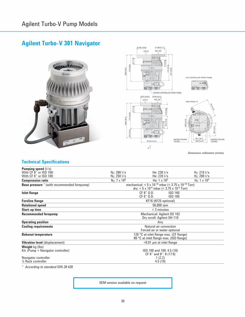
Agilent Turbo-V 301 Navigator
Technical SpecificationsPumping speed (l/s)With CF 8” or ISO 160: N2: 280 l/s He: 230 l/s H2: 210 l/sWith CF 6” or ISO 100: N2: 250 l/s He: 220 l/s H2: 200 l/sCompression ratio N2: 7 x 10⁸ He: 1 x 10⁵ H2: 1 x 10⁴
Base pressure * (with recommended forepump) mechanical: < 5 x 10⁻¹⁰ mbar (< 3.75 x 10⁻¹⁰ Torr)dry: < 5 x 10⁻⁹ mbar (< 3.75 x 10⁻⁹ Torr)
Inlet flange CF 8” O.D. ISO 160CF 6” O.D. ISO 100
Foreline flange KF16 (KF25 optional)Rotational speed 56,000 rpmStart-up time < 3 minutesRecommended forepump Mechanical: Agilent DS 102
Dry scroll: Agilent SH-110Operating position AnyCooling requirements Natural air convection
Forced air or water optionalBakeout temperature 120 °C at inlet flange max. (CF flange)
80 °C at inlet flange max. (ISO flange)Vibration level (displacement) <0.01 µm at inlet flangeWeight kg (lbs)Kit: (Pump + Navigator controller) ISO 100 and 160: 4.5 (10)
CF 6” and 8”: 8 (17.6)Navigator controller 1 (2.2)¼ Rack controller 4.5 (10)* According to standard DIN 28 428.
SEM version available on request
Turbo CD2011.qxd:05 Turbo 13-06-2011 18:30 Pagina 30
31
Turb
o-V
Pum
ps
Ordering Information
Inlet pressure (mbar)
200
010-10
Pum
ping
spee
d (l/
s)
10-4 10-3 10-2 10-1 1
50
250
150
100
10
300
350
10-5
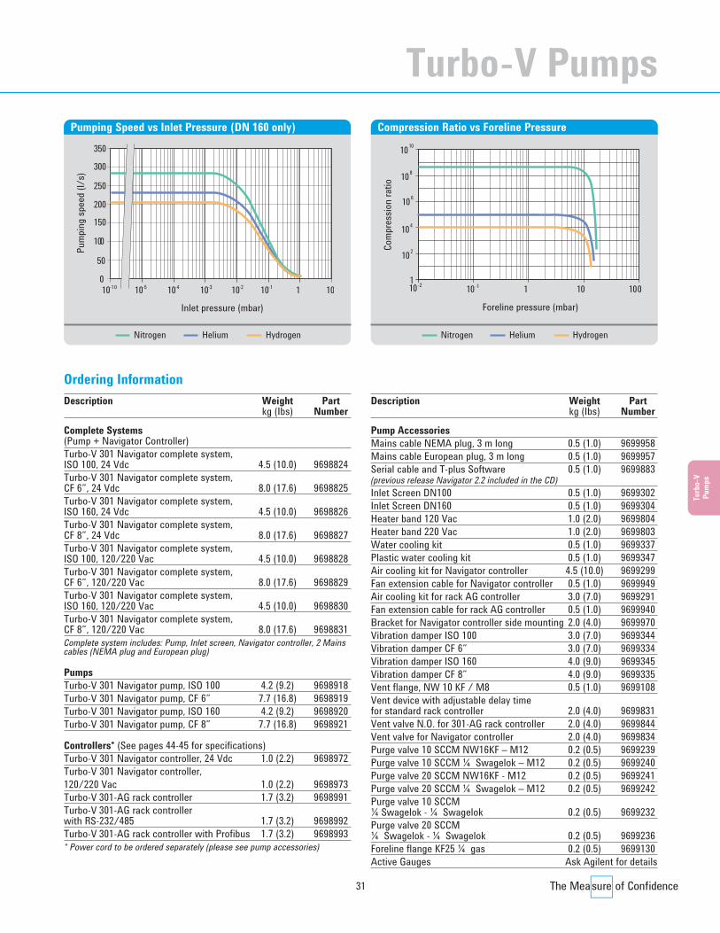
Pumping Speed vs Inlet Pressure (DN 160 only)
10010
1010
108
106
104
Com
pres
sion
ratio
102
10-2 10-1 1
Foreline pressure (mbar)
1
Compression Ratio vs Foreline Pressure
Nitrogen Helium HydrogenNitrogen Helium Hydrogen
Description Weight Partkg (Ibs) Number
Complete Systems(Pump + Navigator Controller)Turbo-V 301 Navigator complete system,ISO 100, 24 Vdc 4.5 (10.0) 9698824Turbo-V 301 Navigator complete system, CF 6”, 24 Vdc 8.0 (17.6) 9698825Turbo-V 301 Navigator complete system,ISO 160, 24 Vdc 4.5 (10.0) 9698826Turbo-V 301 Navigator complete system,CF 8”, 24 Vdc 8.0 (17.6) 9698827Turbo-V 301 Navigator complete system,ISO 100, 120/220 Vac 4.5 (10.0) 9698828Turbo-V 301 Navigator complete system, CF 6”, 120/220 Vac 8.0 (17.6) 9698829Turbo-V 301 Navigator complete system,ISO 160, 120/220 Vac 4.5 (10.0) 9698830Turbo-V 301 Navigator complete system,CF 8”, 120/220 Vac 8.0 (17.6) 9698831Complete system includes: Pump, Inlet screen, Navigator controller, 2 Mainscables (NEMA plug and European plug)
PumpsTurbo-V 301 Navigator pump, ISO 100 4.2 (9.2) 9698918Turbo-V 301 Navigator pump, CF 6” 7.7 (16.8) 9698919Turbo-V 301 Navigator pump, ISO 160 4.2 (9.2) 9698920Turbo-V 301 Navigator pump, CF 8” 7.7 (16.8) 9698921
Controllers* (See pages 44-45 for specifications)Turbo-V 301 Navigator controller, 24 Vdc 1.0 (2.2) 9698972Turbo-V 301 Navigator controller, 120/220 Vac 1.0 (2.2) 9698973Turbo-V 301-AG rack controller 1.7 (3.2) 9698991 Turbo-V 301-AG rack controllerwith RS-232/485 1.7 (3.2) 9698992Turbo-V 301-AG rack controller with Profibus 1.7 (3.2) 9698993* Power cord to be ordered separately (please see pump accessories)
Description Weight Partkg (Ibs) Number
Pump AccessoriesMains cable NEMA plug, 3 m long 0.5 (1.0) 9699958Mains cable European plug, 3 m long 0.5 (1.0) 9699957Serial cable and T-plus Software 0.5 (1.0) 9699883(previous release Navigator 2.2 included in the CD)Inlet Screen DN100 0.5 (1.0) 9699302Inlet Screen DN160 0.5 (1.0) 9699304Heater band 120 Vac 1.0 (2.0) 9699804Heater band 220 Vac 1.0 (2.0) 9699803Water cooling kit 0.5 (1.0) 9699337Plastic water cooling kit 0.5 (1.0) 9699347Air cooling kit for Navigator controller 4.5 (10.0) 9699299Fan extension cable for Navigator controller 0.5 (1.0) 9699949Air cooling kit for rack AG controller 3.0 (7.0) 9699291Fan extension cable for rack AG controller 0.5 (1.0) 9699940Bracket for Navigator controller side mounting 2.0 (4.0) 9699970Vibration damper ISO 100 3.0 (7.0) 9699344Vibration damper CF 6” 3.0 (7.0) 9699334Vibration damper ISO 160 4.0 (9.0) 9699345Vibration damper CF 8” 4.0 (9.0) 9699335Vent flange, NW 10 KF / M8 0.5 (1.0) 9699108Vent device with adjustable delay timefor standard rack controller 2.0 (4.0) 9699831Vent valve N.O. for 301-AG rack controller 2.0 (4.0) 9699844Vent valve for Navigator controller 2.0 (4.0) 9699834 Purge valve 10 SCCM NW16KF – M12 0.2 (0.5) 9699239Purge valve 10 SCCM ¼ Swagelok – M12 0.2 (0.5) 9699240Purge valve 20 SCCM NW16KF - M12 0.2 (0.5) 9699241Purge valve 20 SCCM ¼ Swagelok – M12 0.2 (0.5) 9699242Purge valve 10 SCCM¼ Swagelok - ¼ Swagelok 0.2 (0.5) 9699232Purge valve 20 SCCM¼ Swagelok - ¼ Swagelok 0.2 (0.5) 9699236Foreline flange KF25 ¼ gas 0.2 (0.5) 9699130Active Gauges Ask Agilent for details
Turbo-V Pumps
Turbo CD2011.qxd:05 Turbo 13-06-2011 18:30 Pagina 31
32
Agilent Turbo-V Pump Models
Ø285.0 (11.22) Ø335.0 (13.19)
Ø232.0 (9.13) Ø232.0 (9.13)
294.
3 (1
1.48
)
158.
1 (6
.17)
ISO 160
ISO 200
ISO 250
ISO 200-F ISO 250-F15
8.1
(6.1
7)
252.
8 (9
.86)
279.
4 (1
0.90
)
52.0
(2.0
3)
CFF 10"
322.
7 (1
2.58
)
228.
5 (8
.91)
122.
8 (4
.79)
200.6 (7.82)
70.0
(2.7
3)
52.0
(2.0
3)
ELEC. CONNECTOR
WATER COOLING
WATER COOLING
VENT1020'
WATER COOLING
ELEC. CONNECTOR WATER
COOLING
VENT1020'
1020'
323.
5 (1
2.74
)
350.
6 (1
3.80
)
Ø232.0 (9.13)
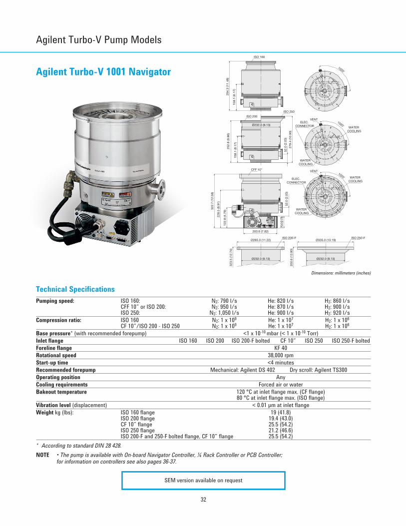
Dimensions: millimeters (inches)
Technical SpecificationsPumping speed: ISO 160: N2: 790 l/s He: 820 l/s H2: 860 l/s
CFF 10” or ISO 200: N2: 950 l/s He: 870 l/s H2: 900 l/sISO 250: N2: 1,050 l/s He: 900 l/s H2: 920 l/s
Compression ratio: ISO 160 N2: 1 x 10⁹ He: 1 x 10⁷ H2: 1 x 10⁶
CF 10”/ISO 200 - ISO 250 N2: 1 x 10⁹ He: 1 x 10⁷ H2: 1 x 10⁶
Base pressure* (with recommended forepump) <1 x 10⁻¹⁰ mbar (< 1 x 10⁻¹⁰ Torr)Inlet flange ISO 160 ISO 200 ISO 200-F bolted CF 10” ISO 250 ISO 250-F boltedForeline flange KF 40Rotational speed 38,000 rpmStart-up time <4 minutesRecommended forepump Mechanical: Agilent DS 402 Dry scroll: Agilent TS300Operating position AnyCooling requirements Forced air or waterBakeout temperature 120 °C at inlet flange max. (CF flange)
80 °C at inlet flange max. (ISO flange)Vibration level (displacement) < 0.01 µm at inlet flangeWeight kg (lbs): ISO 160 flange 19 (41.8)
ISO 200 flange 19.4 (43.0)CF 10” flange 25.5 (54.2)ISO 250 flange 21.2 (46.6)ISO 200-F and 250-F bolted flange, CF 10” flange 25.5 (54.2)
* According to standard DIN 28 428. NOTE • The pump is available with On-board Navigator Controller, ¼ Rack Controller or PCB Controller;
for information on controllers see also pages 36-37.
SEM version available on request
Agilent Turbo-V 1001 Navigator
Turbo CD2011.qxd:05 Turbo 13-06-2011 18:30 Pagina 32
33
Turb
o-V
Pum
ps
010-5
Inlet pressure (mbar)
Pum
ping
spee
d (l/
s)
10-10
200
400
800
1000
1200
10-4 10-3 10-2 10-1 1 10
600
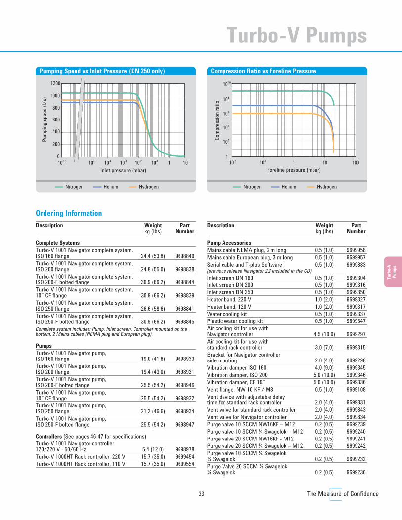
Pumping Speed vs Inlet Pressure (DN 250 only)
110-1 1 10 100
Foreline pressure (mbar)
Com
pres
sion
ratio
10-2
102
104
106
108
1010
Compression Ratio vs Foreline Pressure
Ordering Information
Nitrogen Helium Hydrogen Nitrogen Helium Hydrogen
Description Weight Partkg (Ibs) Number
Complete Systems Turbo-V 1001 Navigator complete system,ISO 160 flange 24.4 (53.8) 9698840Turbo-V 1001 Navigator complete system, ISO 200 flange 24.8 (55.0) 9698838 Turbo-V 1001 Navigator complete system, ISO 200-F bolted flange 30.9 (66.2) 9698844Turbo-V 1001 Navigator complete system, 10” CF flange 30.9 (66.2) 9698839 Turbo-V 1001 Navigator complete system,ISO 250 flange 26.6 (58.6) 9698841 Turbo-V 1001 Navigator complete system, ISO 250-F bolted flange 30.9 (66.2) 9698845Complete system includes: Pump, Inlet screen, Controller mounted on thebottom, 2 Mains cables (NEMA plug and European plug).
PumpsTurbo-V 1001 Navigator pump,ISO 160 flange 19.0 (41.8) 9698933 Turbo-V 1001 Navigator pump,ISO 200 flange 19.4 (43.0) 9698931 Turbo-V 1001 Navigator pump,ISO 200-F bolted flange 25.5 (54.2) 9698946Turbo-V 1001 Navigator pump, 10” CF flange 25.5 (54.2) 9698932 Turbo-V 1001 Navigator pump, ISO 250 flange 21.2 (46.6) 9698934Turbo-V 1001 Navigator pump,ISO 250-F bolted flange 25.5 (54.2) 9698947
Controllers (See pages 46-47 for specifications)Turbo-V 1001 Navigator controller120/220 V - 50/60 Hz 5.4 (12.0) 9698978 Turbo-V 1000HT Rack controller, 220 V 15.7 (35.0) 9699454Turbo-V 1000HT Rack controller, 110 V 15.7 (35.0) 9699554
Description Weight Partkg (Ibs) Number
Pump AccessoriesMains cable NEMA plug, 3 m long 0.5 (1.0) 9699958 Mains cable European plug, 3 m long 0.5 (1.0) 9699957 Serial cable and T-plus Software 0.5 (1.0) 9699883(previous release Navigator 2.2 included in the CD) Inlet screen DN 160 0.5 (1.0) 9699304 Inlet screen DN 200 0.5 (1.0) 9699316 Inlet screen DN 250 0.5 (1.0) 9699350 Heater band, 220 V 1.0 (2.0) 9699327 Heater band, 120 V 1.0 (2.0) 9699317 Water cooling kit 0.5 (1.0) 9699337 Plastic water cooling kit 0.5 (1.0) 9699347 Air cooling kit for use withNavigator controller 4.5 (10.0) 9699297 Air cooling kit for use withstandard rack controller 3.0 (7.0) 9699315 Bracket for Navigator controllerside mouting 2.0 (4.0) 9699298Vibration damper ISO 160 4.0 (9.0) 9699345Vibration damper, ISO 200 5.0 (10.0) 9699346 Vibration damper, CF 10” 5.0 (10.0) 9699336 Vent flange, NW 10 KF / M8 0.5 (1.0) 9699108Vent device with adjustable delaytime for standard rack controller 2.0 (4.0) 9699831Vent valve for standard rack controller 2.0 (4.0) 9699843Vent valve for Navigator controller 2.0 (4.0) 9699834Purge valve 10 SCCM NW16KF – M12 0.2 (0.5) 9699239Purge valve 10 SCCM ¼ Swagelok – M12 0.2 (0.5) 9699240Purge valve 20 SCCM NW16KF - M12 0.2 (0.5) 9699241Purge valve 20 SCCM ¼ Swagelok – M12 0.2 (0.5) 9699242Purge valve 10 SCCM ¼ Swagelok¼ Swagelok 0.2 (0.5) 9699232Purge Valve 20 SCCM ¼ Swagelok¼ Swagelok 0.2 (0.5) 9699236
Turbo-V Pumps
Turbo CD2011.qxd:05 Turbo 13-06-2011 18:30 Pagina 33
34
Agilent Turbo-V Pump Models
Ø284.86 [11.2]
51.0
0 [2
.0]
133.
67 [5
.3]
133.
67 [5
.3]
ELECTRICAL CONNECTOR
135.30 [5.3]
VENTIN-OUT WATER CIRCUIT
GAS PURGE
138.
00 [5
.4]
FORELINE KF40
ELECTRICAL CONNECTOR
290.
00 [1
1.4]
65.0
0 [2
.6]
90.0
0 [3
.5]
145.
50 [5
.7]
65.0
0 [2
.6]
135.30 [5.3]
VENTIN-OUT WATER CIRCUIT
GAS PURGE
138.
00 [5
.4]
FORELINE KF25
Ø225.00 [8.9]
22.0
3 [0
.9]
Turbo-V 1K-GFORELINE KF25
263.
60 [1
0.4]
ELECTRICALCONNECTOR
GAS PURGE
IN-OUT WATER CIRCUIT
VENT
UPPER VIEW ISO 200F
UPPER VIEW ISO 160F
ISO 160F
Water Cooling 1/4"G
ISO 200F
Dimensions: millimeters (inches)
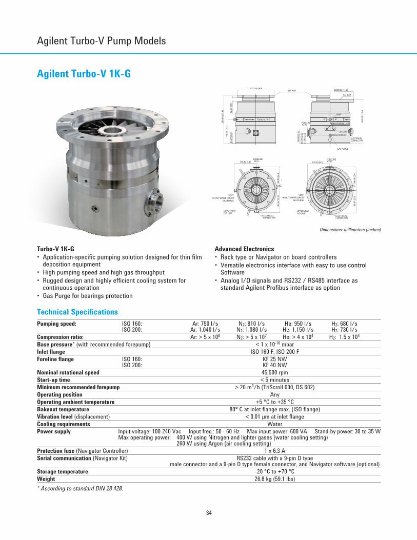
Agilent Turbo-V 1K-G
Technical SpecificationsPumping speed: ISO 160: Ar: 750 l/s N2: 810 l/s He: 950 l/s H2: 680 l/s
ISO 200: Ar: 1,040 l/s N2: 1,080 l/s He: 1,150 l/s H2: 730 l/sCompression ratio: Ar: > 5 x 10⁸ N2: > 5 x 10⁷ He: > 4 x 10⁴ H2: 1.5 x 10⁴
Base pressure* (with recommended forepump) < 1 x 10⁻¹⁰ mbarInlet flange ISO 160 F, ISO 200 FForeline flange ISO 160: KF 25 NW
ISO 200: KF 40 NW Nominal rotational speed 45,500 rpmStart-up time < 5 minutesMinimum recommended forepump > 20 m3/h (TriScroll 600, DS 602)Operating position AnyOperating ambient temperature +5 °C to +35 °CBakeout temperature 80° C at inlet flange max. (ISO flange)Vibration level (displacement) < 0.01 µm at inlet flangeCooling requirements WaterPower supply Input voltage: 100-240 Vac Input freq.: 50 - 60 Hz Max input power: 600 VA Stand-by power: 30 to 35 W
Max operating power: 400 W using Nitrogen and lighter gases (water cooling setting)260 W using Argon (air cooling setting)
Protection fuse (Navigator Controller) 1 x 6.3 ASerial communication (Navigator Kit) RS232 cable with a 9-pin D type
male connector and a 9-pin D type female connector, and Navigator software (optional)Storage temperature -20 °C to +70 °CWeight 26.8 kg (59.1 lbs)* According to standard DIN 28 428.
Advanced Electronics• Rack type or Navigator on board controllers• Versatile electronics interface with easy to use control
Software• Analog I/O signals and RS232 / RS485 interface as
standard Agilent Profibus interface as option
Turbo-V 1K-G• Application-specific pumping solution designed for thin film
deposition equipment• High pumping speed and high gas throughput• Rugged design and highly efficient cooling system for
continuous operation• Gas Purge for bearings protection
Turbo CD2011.qxd:05 Turbo 13-06-2011 18:30 Pagina 34

35
Turb
o-V
Pum
ps
Inlet pressure (mbar)
010-8 10-7 10-6 10-2 1
Pum
ping
spee
d (l/
s)
10-5 10-4 10-3 10-1
1200
1000
600
800
400
200
Pumping Speed vs Inlet Pressure
Foreline pressure (mbar)
1010-1
Com
pres
sion
ratio
1 10
102
104
106
108
1010
100
109
103
105
107
Compression Ratio vs Foreline Pressure
Description Part Number
Pumping SystemsTurbo-V 1K-G ISO160 F 8698961R002Turbo-V 1K-G ISO200 F 8698962R001
ControllersTurbo Controller Navigator, 120V-220V for TV-1KG 9698978M005 Turbo Controller Rack, 120V-220V for TV-1KG 9699454M004
AccessoriesMains cable NEMA Plug, 3 m long 9699958Mains cable European Plug, 3 m long 9699957Serial cable and Navigator Software 9699883Inlet screen ISO 160 9699304Inlet screen ISO 200 9699316Water cooling kit (hose tail G ¼) 9699825Water cooling kit (Inox G ¼) 9699826Vent flange, NW 10 KF / M8 9699108Vent device with adjustable delay time for standard rack controller 9699831Vent valve for standard rack controller 9699843Vent valve for Navigator Controller 9699834Purge valve KF16-M12 20 SCCM 9699241Purge valve 7/16-M12 20 SCCM 9699242
Recommended ForepumpRotary Vane pump DS 602, with 1 ph, worldwide motor 9499335Rotary Vane pump DS 602, with 3 ph, worldwide motor 9499336Rotary Vane pump HS 452, with 1 ph, worldwide motor 9499360Rotary Vane pump HS 652, with 1 ph, worldwide motor 9499365Dry pump TriScroll 600, with 1 ph, worldwide motor PTS06001UNIVDry pump TriScroll 600, with 3 ph, worldwide motor PTS06003UNIVDry pump TriScroll 600 inverter, with 1 ph, worldwide motor PTS06001INV
Ordering Information
Nitrogen Helium HydrogenArgonNitrogen Helium HydrogenArgon
Turbo-V Pumps
Turbo CD2011.qxd:05 Turbo 13-06-2011 18:30 Pagina 35

36
Agilent Turbo-V Pump Models
188,2 (7.34)
INLET SCREEN WITH CENTER-RING
FLANGE ISO 250F
EYEBOLT
PURGE & VENTSWAGELOCK PIPE 1/8
CONTROLLERFRONT PANEL
Ø 310 (12.09)
Ø 335 (13.07)
Ø 11 (0.43) N 12
FORELINE KF 40
WATER COOLING FORRUBBER TUBE DIA 9.0
40 (1.56)
30
45
298 (11.62)
162.8 (6.35)
95 (3
.71)
124.
1 (4
.84)
146
(5.6
9)
245
(9.5
6)
335
(13.
07)
Dimensions: millimeters (inches)
Agilent Turbo-V 2K-G System
Technical SpecificationsPumping speed N2: 1600 l/sCompression ratio N2: 3 x 10⁵
Base pressure* (with recommended forepump) < 1 x 10⁻⁸ mbarInlet flange ISO 250 FForeline flange KF 40 NWNominal rotational speed 33,000 rpmStart-up time <7 minutesRecommended forepump > 40 m3 /hOperating position AnyOperating ambient temperature +5 °C to +40 °CPower supply Input voltage 100 - 240 Vac
Input freq. 50 - 60 HzCommunication Interface Analogue I/O Standard
RS232 / RS485 StandardProfibus Optional
Dimensions Height 335 mm (13.18 in.)Diameter 335 mm (13.18 in.)Weight 35 kg (77 lbs)
* According to standard DIN 28 428.
The System Interface• Integrated package includes Turbo Molecular Pump,
Drive Electronics, Power Supply, Purge Gas and Communication
• Versatile electronics interface with easy to use controlSoftware
• Analog I/O signals and RS232 / RS485 interface asstandard Agilent Profibus interface as option
Turbo-V 2K-G System• The first application-specific pumping solution designed for
thin film deposition equipment• The highest performing, most compact unit available• The first fully integrated approach for maximum system
productivity and uptime
Turbo CD2011.qxd:05 Turbo 13-06-2011 18:30 Pagina 36

37
Turb
o-V
Pum
ps
Inlet pressure (mbar)
010-6
Pum
ping
spee
d (l/
s)
200
10-5 10-4 10-3 10-2 10-1 1
600
1000
14001600
400
800
1200
1800
Pumping Speed vs Inlet Pressure
Outlet pressure (mbar)
110-3
Com
pres
sion
ratio
10
10-2 10 10 10-1
100
1000
100000
10000
1000000
Compression Ratio vs Foreline Pressure
Nitrogen Argon Nitrogen Argon
Description Part Number
Pumping Systems (*)Turbo-V 2K-G system with MoniTorr 9698871Turbo-V 2K-G system with Profibus and MoniTorr 9698873(*) Pumping Systems include Pump with 230 V Integrated Electronics, water hose connection, Inlet Screen with center-ring
and pre-installed IP54 Mating Connectors. Both standard models can be equipped with Agilent’s MoniTorr device on request.Also 120 Vac units available on request.
AccessoriesMains cable NEMA Plug, 3 m long 9699958Mains cable European Plug, 3 m long 9699957T-Plus Software and serial cable 9699883Water cooling kit for 6x8 (IDxOD) flexible tube 9699348Water cooling kit for ⅜ in.ID flexible tube 9699338
Spare PartsIP54 proof mating connectors 9699958Inlet screen ISO 250 with center ring 9699138Water hoses 9699825
Ordering Information
Turbo-V Pumps
Turbo CD2011.qxd:05 Turbo 13-06-2011 18:30 Pagina 37

38
Agilent Turbo-V Pump Models
PURGE/VENTVALVES PORT
VENT HOLE ONENVELOPE
EYEBOLT
CENTER-RING (ISO 250F)
Ø 334.90 [Ø 13.19]
FLANGEISO 250F
WATER COOLINGFOR RUBBERTUBE Ø 9.0
VENT
GND HOLE
CONTROLLERFRONT PANEL
UPPER VIEW
BOTTOM VIEW
PURGE/VENTVALVES PORT
FORELINE KF 40
WATER COOLINGFOR RUBBERTUBE Ø 9.0
Dimensions: millimeters (inches)
Agilent Turbo-V 3K-G System
Technical SpecificationsPumping speed N2: 2200 l/s He: 1900 l/s Ar: 2050 l/sCompression ratio N2: > 1 x 10⁷ He: 6 x 10³ Ar: > 1 x 10⁸
Base pressure* (with recommended forepump) <1 x 10⁻⁸ mbarInlet flange ISO 250 FForeline flange KF 40 NWNominal rotational speed 31,800 rpmStart-up time without gas load and with the recommended forepump < 6 minutesForeline pressure < 0.5 mbarMinimum recommended forepump > 60 m3/h (depending on gasflow requirements)Operating position AnyCooling requirements WaterWeight (ISO 250) 52 kg (114.63 lbs)* According to standard DIN 28 428.
Best Footprint to Performance Ratio• The highest Argon pumping speed (2050 l/s) for its size
allows uniform deposition rates at high substrate throughput• Highest pumping speed in its class: 2200 l/s for Nitrogen• Throughput: over 1400 sccm for Nitrogen• The all-turbo, more compact rotor design delivers highest
performance with the smallest footprint
The Only Truly “Integrated” System in the Market The Turbo-V 3K-G: an advanced solution for Thin Filmapplications• Fully integrated system with on board waterproof power supply• Vent/purge valves control capability• Integrated diagnostics• Multiple interfaced capability• Lowest power absorption
Turbo CD2011.qxd:05 Turbo 13-06-2011 18:30 Pagina 38
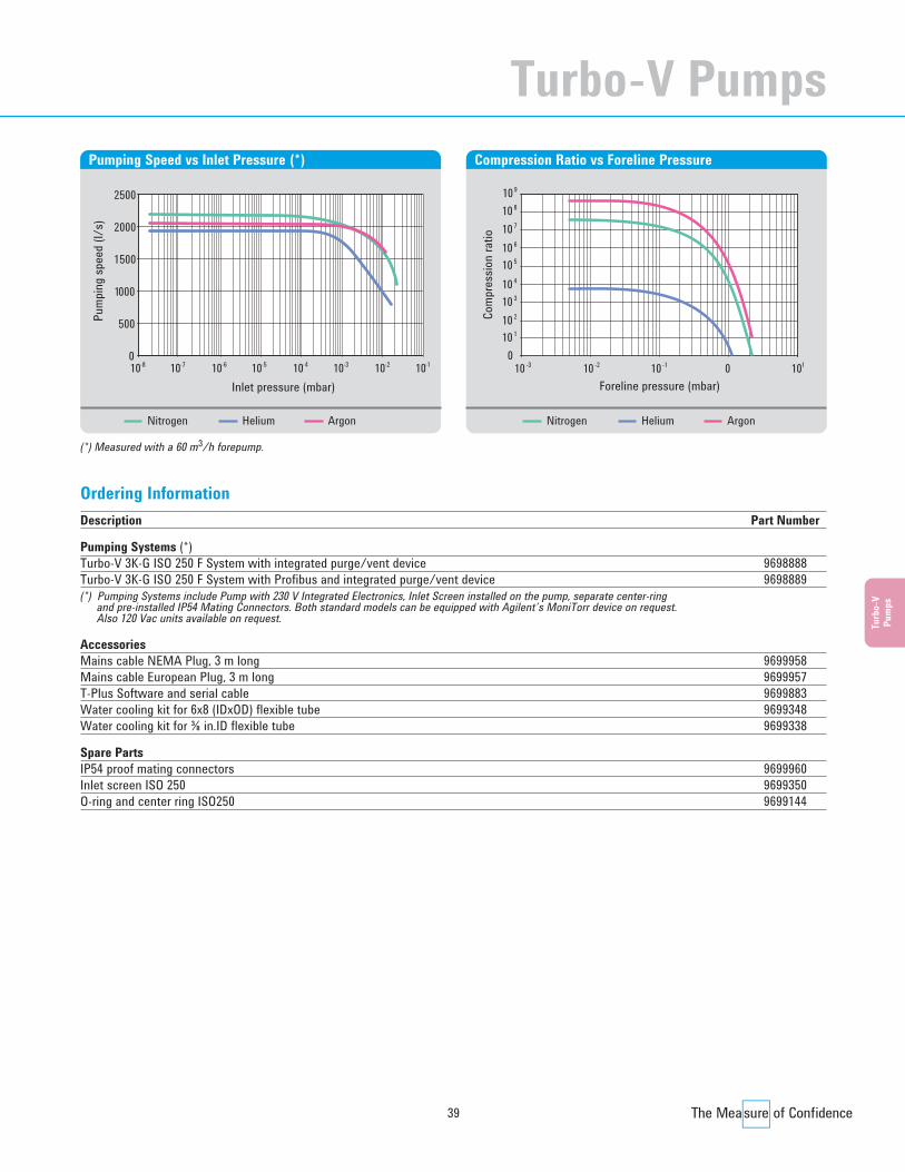
39
Turb
o-V
Pum
ps
Description Part Number
Pumping Systems (*)Turbo-V 3K-G ISO 250 F System with integrated purge/vent device 9698888Turbo-V 3K-G ISO 250 F System with Profibus and integrated purge/vent device 9698889(*) Pumping Systems include Pump with 230 V Integrated Electronics, Inlet Screen installed on the pump, separate center-ring
and pre-installed IP54 Mating Connectors. Both standard models can be equipped with Agilent’s MoniTorr device on request. Also 120 Vac units available on request.
AccessoriesMains cable NEMA Plug, 3 m long 9699958Mains cable European Plug, 3 m long 9699957T-Plus Software and serial cable 9699883Water cooling kit for 6x8 (IDxOD) flexible tube 9699348Water cooling kit for ⅜ in.ID flexible tube 9699338
Spare PartsIP54 proof mating connectors 9699960Inlet screen ISO 250 9699350O-ring and center ring ISO250 9699144
Ordering Information
10-8 10-7 10-6 10-5 10-4 10-3 10-20
500
1000
1500
2000
2500
Inlet pressure (mbar)
Pum
ping
spee
d (l/
s)
10-1
Pumping Speed vs Inlet Pressure (*)
Com
pres
sion
ratio
Foreline pressure (mbar)10-3
0
10 2
10 1
10 310 4
10 5
10 7
10 6
10 8
10 9
10-2 10 0 10-1 1
Compression Ratio vs Foreline Pressure
Nitrogen Helium Argon Nitrogen Helium Argon
(*) Measured with a 60 m3/h forepump.
Turbo-V Pumps
Turbo CD2011.qxd:05 Turbo 13-06-2011 18:30 Pagina 39

40
Agilent Turbo-V Pump Models
786
(30.
94)
ISO 500ISO 500
ISO 100
60°
20°
60°
20°
M12
KF 10
Vent port
Foreline port
Ø 550 (21.65)
Ø 606.3 (23.87)
Ø 240 (9.45)
195 (7.67)Ø 620 (24.41)
Ø 556 (21.89)
315
(12.
4)
513
(20.
19)
760
(29.
92)
303
(11.
93)
87 (3
.42)
19 (0
.75)
358
(14.
09)
58 (2
.28)
300
(11.
81)
8 (0.31)
Dimensions: millimeters (inches)
Agilent Turbo-V 6000
Technical SpecificationsPumping speed (l/s) N2: 6,000 He: 7,000 H2: 6,500Compression ratio N2: 1 x 10¹⁰ He: 2.3 x 10⁵ H2: 8 x 10³
Base pressure (with recommended mechanical pump) <1 x 10⁻¹⁰ mbar (< 1 x 10⁻¹⁰ Torr)Inlet flange ISO 500Foreline flange ISO 100Rotational speed 14,000 rpmStartup time 30 minutesRecommended forepump 80 m3/hOperating position Vertical ±10°Cooling requirements WaterBakeout temperature 80 °C at inlet flange (ISO version)Vibration level (displacement) ≤ 0.05 µm at inlet flangeWeight kg (lbs) 250 (550)Lubricant Agilent T.A. oil (charge 1,000 cm3)
Turbo CD2011.qxd:05 Turbo 13-06-2011 18:30 Pagina 40
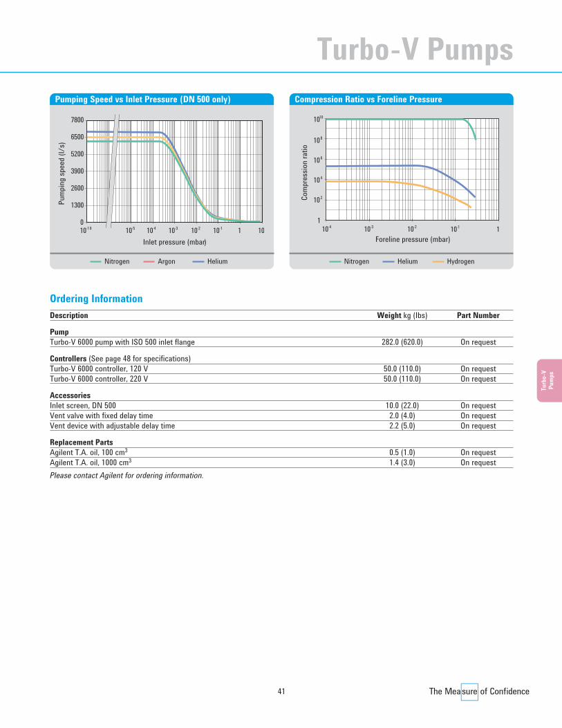
41
Turb
o-V
Pum
ps
Description Weight kg (Ibs) Part Number
PumpTurbo-V 6000 pump with ISO 500 inlet flange 282.0 (620.0) On request
Controllers (See page 48 for specifications)Turbo-V 6000 controller, 120 V 50.0 (110.0) On request Turbo-V 6000 controller, 220 V 50.0 (110.0) On request
AccessoriesInlet screen, DN 500 10.0 (22.0) On request Vent valve with fixed delay time 2.0 (4.0) On request Vent device with adjustable delay time 2.2 (5.0) On request
Replacement PartsAgilent T.A. oil, 100 cm3 0.5 (1.0) On request Agilent T.A. oil, 1000 cm3 1.4 (3.0) On request Please contact Agilent for ordering information.
Ordering Information
Inlet pressure (mbar)
3900
010-10
Pum
ping
spee
d (l/
s)
10-5 10-4 10-3 10-2 10-1 10
5200
2600
1300
1
6500
7800
Pumping Speed vs Inlet Pressure (DN 500 only)
110-3 10-2 10-1 1
Foreline pressure (mbar)
Com
pres
sion
ratio
10-4
102
104
106
108
1010
Compression Ratio vs Foreline Pressure
Nitrogen Argon Helium Nitrogen Helium Hydrogen
Turbo-V Pumps
Turbo CD2011.qxd:05 Turbo 13-06-2011 18:30 Pagina 41

42
59.0
(2.3
)91
.0 (3
.6)
72.7
(2.9
)17
.9 (0
.7)
4.5
(0.2
)
107.0 (4.2) 107.0 (4.2)
91.0 (3.6)
68.5 (2.7)21.4 (0.8) 4x3MA LMAX=8mm
3x5MA LMAX=8mm
Dimensions: millimeters (inches)
The dedicated controller is a solid-state frequency converterwhich is driven by a single chip microcomputer and consists of two PCBs which include power supply and 3-phase output,analog and input/output section, microprocessor and digitalsection. The power supply, together with the 3-phase output,converts the single phase AC mains supply or 24Vdc supplyinto a 3-phase, low voltage, medium frequency output which isrequired to power the pump. The controller can be operatedby a remote host computer via the serial connection. A Windows-based software is available (optional).The Turbo-V 81-AG Navigator controller can be mounted onboard, on the bottom of the Turbo-V 81 Series pumps.
The Turbo-V 81-AG Navigator controller is a solid-statefrequency converter with the following features:• Drives the pumps of the Turbo-V 81 family.• Powers the pump cooling fan.• Drives the vent valve.• Provides and acquires the pressure of the wide range gauge.• Remote I/Os compatible with the previous version.• Navigator default serial compatible with the previous RS 232
and 485 version.• Able to operate with Active Gauges (IM-500, Full Range
Gauge FRG-700 and FRG-702).
Agilent Pump Controllers
Technical SpecificationsInput voltages:Navigator controller, 24 Vdc 24 Vdc ±10%Navigator controller, 100/240 Vac 100 ÷ 240 Vac ±10%Input power:Navigator controller, 24 Vdc 80 WNavigator controller, 100/240 Vac 180 VAInput frequency:Navigator controller, 100/240 Vac 50 to 60 Hz ±5%Fuse 2 x T4 A 250 VOutput voltage 60 VacOutput frequency 1350 HzOutput power: Navigator controller, 24 Vdc 50 WNavigator controller, 100/240 Vac 70 W (ramp),
50 W (Normal and Autotuning)Operating temperature +5 ÷ +45 °C
0 – 90% (Not condensing)Storage temperature -20 °C to +70 °C
0 – 95%
Ordering InformationDescription Weight Part
kg (Ibs) Number
ControllersTurbo-V 81-AG Navigator controller*,24 Vdc 0.3 (0.66) 9698995Turbo-V 81-AG Navigator controller*,100/240 Vac 0.3 (0.66) 9698996* Order power cable separately
AccessoriesMains cable NEMA Plug, 3 m long 9699958Mains cable European Plug, 3 m long 9699957Serial cable and T-Plus Software 9699883Air cooling kit (0.5 m) 9699290Air cooling kit, extension cable (5 m) 9699940Vent valve N.O. 0.5 mm orifice (0.7 m cable) 9699844Vent valve extension cable(5 m, USB Type A - USB Type A) 9699941Active Gauges Ask Agilent for detailsActive Gauges cables Ask Agilent for details
Agilent Turbo-V 81-AG Navigator Controller
Turbo CD2011.qxd:05 Turbo 13-06-2011 18:30 Pagina 42
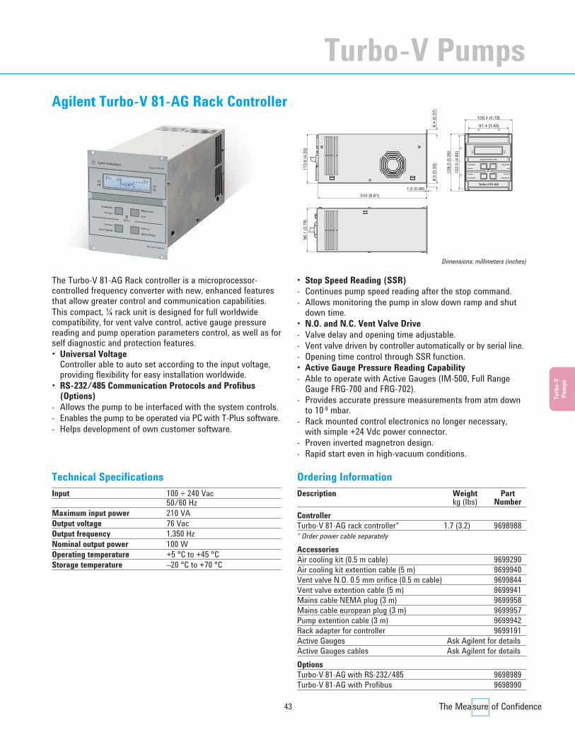
43
Turb
o-V
Pum
ps
Turbo-V 81-AG
244 (9.61)
106.4 (4.19)
91.4 (3.60)= =
1.5 (0.06)
9.4
(0.3
7)8.
5 (0
.33)
128.
5 (5
.06)
110.
6 (4
.35)
96.1
(3.7
8)
122.
5 (4
.82)
==
Dimensions: millimeters (inches)
• Stop Speed Reading (SSR)- Continues pump speed reading after the stop command.- Allows monitoring the pump in slow down ramp and shut
down time.• N.O. and N.C. Vent Valve Drive- Valve delay and opening time adjustable.- Vent valve driven by controller automatically or by serial line.- Opening time control through SSR function.• Active Gauge Pressure Reading Capability- Able to operate with Active Gauges (IM-500, Full Range
Gauge FRG-700 and FRG-702).- Provides accurate pressure measurements from atm down
to 10-9 mbar.- Rack mounted control electronics no longer necessary,
with simple +24 Vdc power connector.- Proven inverted magnetron design.- Rapid start even in high-vacuum conditions.
The Turbo-V 81-AG Rack controller is a microprocessor-controlled frequency converter with new, enhanced featuresthat allow greater control and communication capabilities.This compact, ¼ rack unit is designed for full worldwidecompatibility, for vent valve control, active gauge pressurereading and pump operation parameters control, as well as forself diagnostic and protection features.• Universal Voltage
Controller able to auto set according to the input voltage,providing flexibility for easy installation worldwide.
• RS-232/485 Communication Protocols and Profibus(Options)
- Allows the pump to be interfaced with the system controls.- Enables the pump to be operated via PC with T-Plus software.- Helps development of own customer software.
Technical SpecificationsInput 100 ÷ 240 Vac
50/60 HzMaximum input power 210 VAOutput voltage 76 VacOutput frequency 1,350 HzNominal output power 100 WOperating temperature +5 °C to +45 °CStorage temperature –20 °C to +70 °C
Ordering InformationDescription Weight Part
kg (Ibs) NumberControllerTurbo-V 81-AG rack controller* 1.7 (3.2) 9698988* Order power cable separately
AccessoriesAir cooling kit (0.5 m cable) 9699290Air cooling kit extention cable (5 m) 9699940Vent valve N.O. 0.5 mm orifice (0.5 m cable) 9699844Vent valve extention cable (5 m) 9699941Mains cable NEMA plug (3 m) 9699958Mains cable european plug (3 m) 9699957Pump extention cable (3 m) 9699942Rack adapter for controller 9699191Active Gauges Ask Agilent for detailsActive Gauges cables Ask Agilent for detailsOptionsTurbo-V 81-AG with RS-232/485 9698989 Turbo-V 81-AG with Profibus 9698990
Agilent Turbo-V 81-AG Rack Controller
Turbo-V Pumps
Turbo CD2011.qxd:05 Turbo 13-06-2011 18:30 Pagina 43
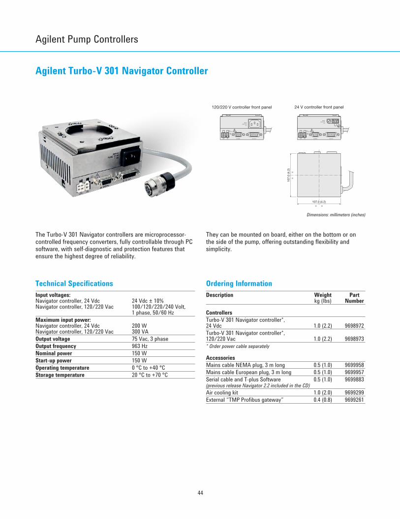
44
Agilent Pump Controllers
Agilent Turbo-V 301 Navigator Controller
24 V controller front panel
FUSE TYPE
T 8A
MAINS
T 3A
FUSE TYPE
MAINS
VENTP3
J6 SERIALFANP5
STATUSLD1
J5 IN-OUTP5
FANP3
VENT
LD1STATUS
J6 SERIAL J5 IN-OUT
120/220 V controller front panel
107.0 (4.2)= =
==
107.
0 (4
.2)
The Turbo-V 301 Navigator controllers are microprocessor-controlled frequency converters, fully controllable through PCsoftware, with self-diagnostic and protection features thatensure the highest degree of reliability.
They can be mounted on board, either on the bottom or onthe side of the pump, offering outstanding flexibility andsimplicity.
Technical SpecificationsInput voltages:Navigator controller, 24 Vdc 24 Vdc ± 10%Navigator controller, 120/220 Vac 100/120/220/240 Volt,
1 phase, 50/60 HzMaximum input power:Navigator controller, 24 Vdc 200 WNavigator controller, 120/220 Vac 300 VAOutput voltage 75 Vac, 3 phaseOutput frequency 963 HzNominal power 150 WStart-up power 150 WOperating temperature 0 °C to +40 °CStorage temperature 20 °C to +70 °C
Ordering InformationDescription Weight Part
kg (Ibs) Number
ControllersTurbo-V 301 Navigator controller*,24 Vdc 1.0 (2.2) 9698972Turbo-V 301 Navigator controller*,120/220 Vac 1.0 (2.2) 9698973* Order power cable separately
AccessoriesMains cable NEMA plug, 3 m long 0.5 (1.0) 9699958Mains cable European plug, 3 m long 0.5 (1.0) 9699957Serial cable and T-plus Software 0.5 (1.0) 9699883(previous release Navigator 2.2 included in the CD) Air cooling kit 1.0 (2.0) 9699299External “TMP Profibus gateway” 0.4 (0.8) 9699261
Dimensions: millimeters (inches)
Turbo CD2011.qxd:05 Turbo 13-06-2011 18:30 Pagina 44

45
Turb
o-V
Pum
ps
Agilent Turbo-V 301-AG Rack Controller
Turbo-V 301-AG
244 (9.61)
106.4 (4.19)
91.4 (3.60)= =
1.5 (0.06)
9.4
(0.3
7)8.
5 (0
.33)
128.
5 (5
.06)
110.
6 (4
.35)
96.1
(3.7
8)
122.
5 (4
.82)
==
• Stop Speed Reading (SSR)- Continues pump speed reading after the stop command.- Allows monitoring the pump in slow down ramp and shut
down time.• N.O. and N.C. Vent Valve Drive- Valve delay and opening time adjustable.- Vent valve driven by controller automatically or by serial line.- Opening time control through SSR function.• Active Gauge Pressure Reading Capability- Able to operate with Active Gauges (IM-500, Full Range
Gauge FRG-700 and FRG-702).- Provides accurate pressure measurements from atm down
to 10-9 mbar.- Rack mounted control electronics no longer necessary,
with simple +24 Vdc power connector.- Proven inverted magnetron design.- Rapid start even in high-vacuum conditions.
The Turbo-V 81-AG Rack controller is a microprocessor-controlled frequency converter with new, enhanced featuresthat allow greater control and communication capabilities.This compact, ¼ rack unit is designed for full worldwidecompatibility, for vent valve control, active gauge pressurereading and pump operation parameters control, as well asfor self diagnostic and protection features.• Universal Voltage
Controller able to auto set according to the input voltage,providing flexibility for easy installation worldwide.
• RS-232/485 Communication Protocols and Profibus(Options)
- Allows the pump to be interfaced with the system controls.- Enables the pump to be operated via PC with T-Plus software.- Helps development of own customer software.
Technical SpecificationsInput 100 ÷ 240 Vac
50/60 HzMaximum input power 300 VAOutput voltage 75 VacOutput frequency 963 HzNominal output power 150 WOperating temperature +5 °C to +45 °CStorage temperature –20 °C to +70 °C
Ordering InformationDescription Weight Part
kg (Ibs) NumberControllerTurbo-V 301-AG rack controller* 1.7 (3.2) 9698991* Order power cable separately
AccessoriesAir cooling kit (0.5 m cable) 9699291Air cooling kit extention cable (5 m) 9699940Vent valve N.O. 0.5 mm orifice (0.5 m cable) 9699844Vent valve extention cable (5 m) 9699941Mains cable NEMA plug (3 m) 9699958Mains cable european plug (3 m) 9699957Pump extention cable (3 m) 9699942Rack adapter for controller 9699191Active Gauges Ask Agilent for detailsActive Gauges cables Ask Agilent for detailsOptionsTurbo-V 301-AG rack controller with RS-232/485 9698992 Turbo-V 301-AG rack controller with Profibus 9698993
Dimensions: millimeters (inches)
Turbo-V Pumps
Turbo CD2011.qxd:05 Turbo 13-06-2011 18:30 Pagina 45
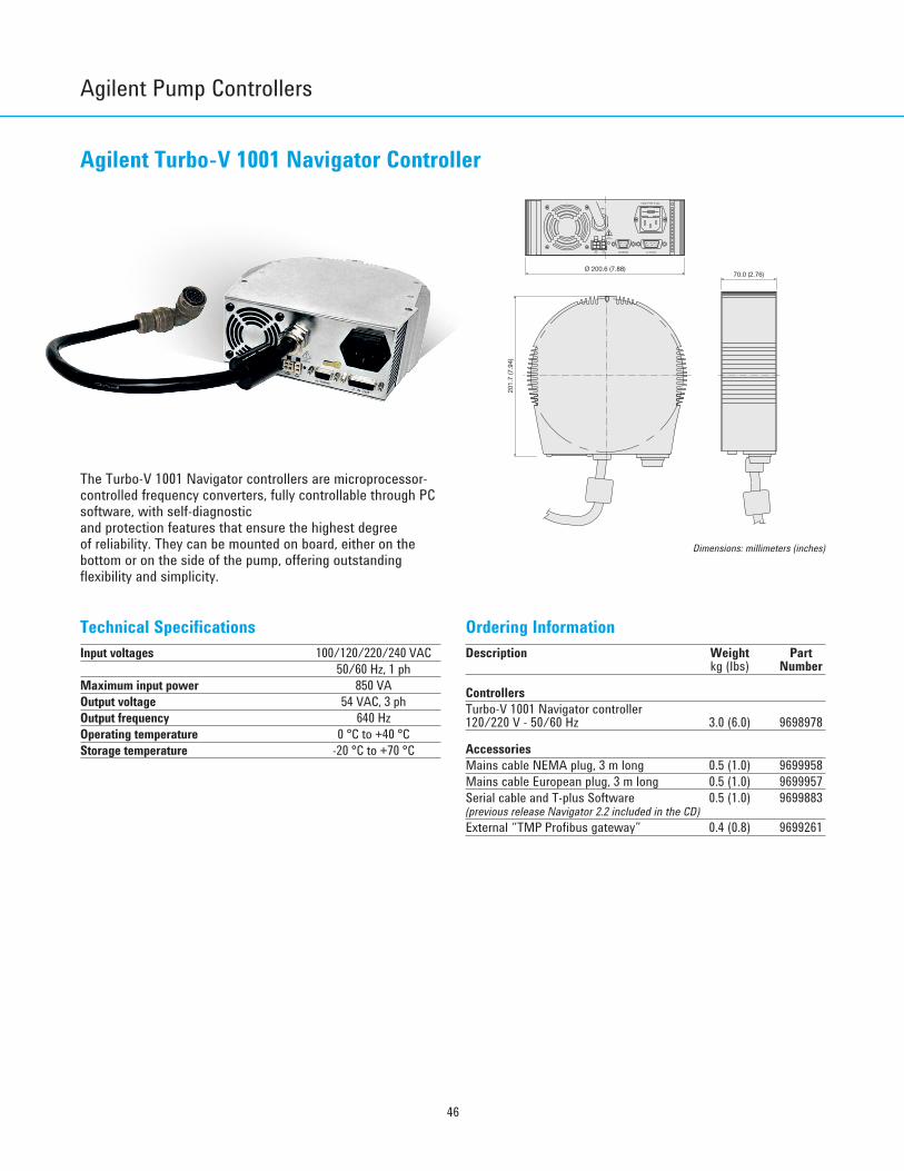
46
Agilent Pump Controllers
Agilent Turbo-V 1001 Navigator Controller
LD1
J1 IN-OUTJ2 SERIAL
STATUS
P4P3VENT FAN
FUSE TYPE T XXA
MP
Ø 200.6 (7.88)70.0 (2.76)
201.
7 (7
.94)
The Turbo-V 1001 Navigator controllers are microprocessor-controlled frequency converters, fully controllable through PCsoftware, with self-diagnostic and protection features that ensure the highest degree of reliability. They can be mounted on board, either on thebottom or on the side of the pump, offering outstandingflexibility and simplicity.
Technical SpecificationsInput voltages 100/120/220/240 VAC
50/60 Hz, 1 phMaximum input power 850 VAOutput voltage 54 VAC, 3 phOutput frequency 640 Hz Operating temperature 0 °C to +40 °C Storage temperature -20 °C to +70 °C
Ordering InformationDescription Weight Part
kg (Ibs) Number
ControllersTurbo-V 1001 Navigator controller120/220 V - 50/60 Hz 3.0 (6.0) 9698978
AccessoriesMains cable NEMA plug, 3 m long 0.5 (1.0) 9699958 Mains cable European plug, 3 m long 0.5 (1.0) 9699957 Serial cable and T-plus Software 0.5 (1.0) 9699883(previous release Navigator 2.2 included in the CD) External “TMP Profibus gateway” 0.4 (0.8) 9699261
Dimensions: millimeters (inches)
Turbo CD2011.qxd:05 Turbo 13-06-2011 18:30 Pagina 46

47
Turb
o-V
Pum
ps
Agilent Turbo-V 1000HT Rack Controller
These controllers are microprocessor-controlled frequencyconverters with self diagnostic and protection features thatensure the highest degree of reliability. The compact, ½ rackunit has a multifunction alphanumeric display for pump statusand error code diagnostics. The front panel has a two-line dotmatrix LCD display with back lighting. It displays rotationalspeed as the pump starts up and indicates when full speed isreached. At any time during the operation of the pump, thespeed, current, power, and bearing temperature can bedisplayed. Additionally, the microprocessor acts as a pump
cycle log, and can display the number of vacuum cycles, the cycle time for the current cycle, and the total operatinghours on the pump. Remote operation can be accomplishedwith logic level contact closures and with optional computer interfaces.PCB controllers are available. Please contact Agilent for details.
Technical SpecificationsInput voltages 100-120 V / 220-240 V
1 ph, 50/60 HzMaximum input power 700 VAOutput voltage 56 VAC, 3 phOutput frequency 633 HzMaximum output power* 450 WStartup power 430 WOperating temperature 0 °C to +40 °CStorage temperature -20 °C to +70 °C* Data valid for nitrogen.
Ordering InformationDescription Weight Part
kg (Ibs) Number
ControllerTurbo-V1000HT Rack controller, 120 V 15.7 (35.0) 9699554 Turbo-V1000HT Rack controller, 220 V 15.7 (35.0) 9699454
AccessoriesJ1 input mating connector 0.5 (1.0) 9699853P6 and P7 mating plug 0.5 (1.0) 9699854Mains cable (European plug, 3 m long) 1.0 (2.0) 9699957Mains cable (American plug, 120 V, 3 m long) 1.0 (2.0) 9699958
OptionsRS485 Computer communication kit 5.0 (1.0) 9699856 RS232 Computer communication kit 5.0 (1.0) 9699857 RS422 Computer communication kit 5.0 (1.0) 9699858 P2 output mating connector 5.0 (1.0) 9699852Rack adapter for controller 2.0 (4.0) 9699191 Controller to pump extension cable(5 m extension) for Turbo-V 1000HT 1.0 (2.0) 9699951L0500Controller to pump extension cable(10 m extension) for Turbo-V 1000HT 2.0 (4.0) 9699951L1000External “TMP Profibus gateway”(usable only with RS-485 option installed) 0.4 (0.8) 9699261
POWER
START
TEMPERATUREPUMP CURRENT
STOP RESET
PUMP LIFE
CYCLE NUMBER
LOW SPEED
CYCLE TIME
255 (10.03) (*)
280 (11.02) (*)
2.5
(0.0
1)
127.
5 (5
.02)
198.1 (7.8)
212 (8.34)
Dimensions: millimeters (inches)
Turbo-V Pumps
Turbo CD2011.qxd:05 Turbo 13-06-2011 18:30 Pagina 47

48
Agilent Pump Controllers
Agilent Turbo-V 6000 Rack Controller
The Turbo-V 6000 controller is a 19” rack mountable unit.This controller provides the following features:Remote Operation with System ControllerThe Turbo-V controller can accept remote commands witheither TTL-compatible logic level signals or with permanentcontact closures.A signal (logic level) indicates that the pump is operating andhas achieved normal speed. Also available is the indication ofoverload due to high-temperature or high-current levels.System DiagnosticsFront panel LED bar graph displays the controller outputfrequency and the power drawn by the pump. An overloadcondition is also indicated and an hour counter monitors theoperating hours on the pump to help adhere to therecommended maintenance intervals.Control of other System ComponentsThe Turbo-V controller can power the mechanical pumpcontactor to provide a one-switch control of both Turbo-V andmechanical pump startup. Simultaneous starting of the Turbo-V and mechanical pump is recommended for mostapplications where no high-vacuum valve is required.
The Turbo-V controller provides power to a turbo vent valve, if used.A starting interlock is available that can be used for delayedstarting of the Turbo-V with a contact closure from a vacuumgauge set point. The interlock could also be integrated to awater-flow switch to provide an early warning of interruptedcooling of the pump.High-pressure OperationThe controller’s ability to adjust the Turbo-V pump’s rotationalspeed under high gas load conditions extends the operatingrange of the Turbo-V pumps into the 10-1 mbar range.RPM DisplayDigital display of nominal pump speed.
Technical SpecificationsInput voltages: 120/220 V, 1 ph, 50/60 HzMaximum input power: 300 VAOutput voltage 100 Vac, 3 phOutput frequency 233 HzNominal power 1,500 WStart-up power 2,200 WOperating temperature 0 °C to +40 °CStorage temperature -20 °C to +70 °C* Data valid for nitrogen
Ordering InformationDescription Weight Part
kg (Ibs) Number
ControllersTurbo-V 6000 Rack controller, 220 V 50.0 (110.0) On request Turbo-V 6000 Rack controller, 120 V 50.0 (110.0) On request Please contact Agilent for ordering information.
443
(17.
44)
293 (11.54) 30 (1.18)
14 (0
.55)
123
(4.8
4)
482 (18.98)
132
(5.2
0)
POWER
START
TEMPERATUREPUMP CURRENT
STOP RESET
PUMP LIFE
CYCLE NUMBER
LOW SPEED
Turbo-V 6000
CYCLE TIME
Dimensions: millimeters (inches)
Turbo CD2011.qxd:05 Turbo 13-06-2011 18:30 Pagina 48
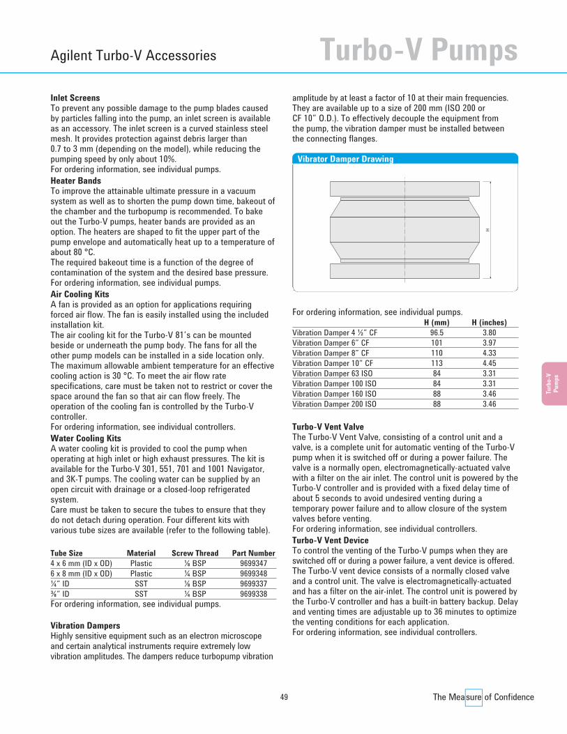
49
Turb
o-V
Pum
ps
Agilent Turbo-V Accessories
Inlet ScreensTo prevent any possible damage to the pump blades causedby particles falling into the pump, an inlet screen is availableas an accessory. The inlet screen is a curved stainless steelmesh. It provides protection against debris larger than 0.7 to 3 mm (depending on the model), while reducing thepumping speed by only about 10%.For ordering information, see individual pumps.Heater BandsTo improve the attainable ultimate pressure in a vacuumsystem as well as to shorten the pump down time, bakeout ofthe chamber and the turbopump is recommended. To bakeout the Turbo-V pumps, heater bands are provided as anoption. The heaters are shaped to fit the upper part of thepump envelope and automatically heat up to a temperature ofabout 80 °C. The required bakeout time is a function of the degree ofcontamination of the system and the desired base pressure.For ordering information, see individual pumps.Air Cooling KitsA fan is provided as an option for applications requiringforced air flow. The fan is easily installed using the includedinstallation kit.The air cooling kit for the Turbo-V 81’s can be mountedbeside or underneath the pump body. The fans for all theother pump models can be installed in a side location only. The maximum allowable ambient temperature for an effectivecooling action is 30 °C. To meet the air flow ratespecifications, care must be taken not to restrict or cover thespace around the fan so that air can flow freely. Theoperation of the cooling fan is controlled by the Turbo-Vcontroller.For ordering information, see individual controllers.Water Cooling KitsA water cooling kit is provided to cool the pump whenoperating at high inlet or high exhaust pressures. The kit isavailable for the Turbo-V 301, 551, 701 and 1001 Navigator,and 3K-T pumps. The cooling water can be supplied by anopen circuit with drainage or a closed-loop refrigeratedsystem.Care must be taken to secure the tubes to ensure that theydo not detach during operation. Four different kits withvarious tube sizes are available (refer to the following table).
Tube Size Material Screw Thread Part Number4 x 6 mm (ID x OD) Plastic ⅛ BSP 96993476 x 8 mm (ID x OD) Plastic ¼ BSP 9699348¼” ID SST ⅛ BSP 9699337⅜” ID SST ¼ BSP 9699338For ordering information, see individual pumps.
Vibration DampersHighly sensitive equipment such as an electron microscope and certain analytical instruments require extremely lowvibration amplitudes. The dampers reduce turbopump vibration
amplitude by at least a factor of 10 at their main frequencies.They are available up to a size of 200 mm (ISO 200 or CF 10” O.D.). To effectively decouple the equipment from the pump, the vibration damper must be installed betweenthe connecting flanges.
For ordering information, see individual pumps.H (mm) H (inches)
Vibration Damper 4 ½” CF 96.5 3.80 Vibration Damper 6” CF 101 3.97Vibration Damper 8” CF 110 4.33Vibration Damper 10” CF 113 4.45Vibration Damper 63 ISO 84 3.31 Vibration Damper 100 ISO 84 3.31 Vibration Damper 160 ISO 88 3.46 Vibration Damper 200 ISO 88 3.46
Turbo-V Vent ValveThe Turbo-V Vent Valve, consisting of a control unit and avalve, is a complete unit for automatic venting of the Turbo-Vpump when it is switched off or during a power failure. Thevalve is a normally open, electromagnetically-actuated valvewith a filter on the air inlet. The control unit is powered by theTurbo-V controller and is provided with a fixed delay time ofabout 5 seconds to avoid undesired venting during atemporary power failure and to allow closure of the systemvalves before venting.For ordering information, see individual controllers.Turbo-V Vent DeviceTo control the venting of the Turbo-V pumps when they areswitched off or during a power failure, a vent device is offered.The Turbo-V vent device consists of a normally closed valveand a control unit. The valve is electromagnetically-actuatedand has a filter on the air-inlet. The control unit is powered bythe Turbo-V controller and has a built-in battery backup. Delayand venting times are adjustable up to 36 minutes to optimizethe venting conditions for each application.For ordering information, see individual controllers.
H
Vibrator Damper Drawing
Turbo-V Pumps
Turbo CD2011.qxd:05 Turbo 13-06-2011 18:30 Pagina 49
50
Handheld TerminalThe handheld terminal is a remote control display for use withV 81 series Turbo-V pumps when connected to a controllerwithout a front panel. It consists of an LCD alphanumericdisplay and keyboard which provide useful real timeindications of the operating conditions and parameters of theturbopump.Moreover, it allows the reprogramming of the controllerparameters and troubleshooting of the pump and controller. The handheld terminal is connected to and powered from the
Turbo-V controller through a 1.5 meter cable.For ordering information, please call your local Agilent Office.Purge ValveTo protect the bearings of a turbomolecular pump used withaggressive process gases, a measured supply of inert gas (N2, Ar) must flow into the pump body around the upperbearing toward the fore-vacuum line. The Agilent fixed orificepurge valve is calibrated for nitrogen to provide the correctgas flow to safely operate Turbo-V pumps. See Fixed OrificePurge Valve Selection Guide below.
Fixed Orifice Purge Valve Selection Guide
Ordering InformationPump model N2 Gas Line Weight Part
Flowrate Connection kg (Ibs) Number
V301/1001 Navigator, and 3K-G models without integrated purge/vent10 SCCM NW16KF 0.2 (0.5) 9699239 10 SCCM ¼ Swagelok 0.2 (0.5) 9699240 20 SCCM NW16KF 0.2 (0.5) 9699241 20 SCCM ¼ Swagelok 0.2 (0.5) 9699242 10 SCCM ¼ Swagelok – ¼ Swagelok* 0.2 (0.5) 9699232 20 SCCM ¼ Swagelok – ¼ Swagelok* 0.2 (0.5) 9699236
* For remote installation
Agilent Turbo-V Accessories
Turbo CD2011.qxd:05 Turbo 13-06-2011 18:30 Pagina 50
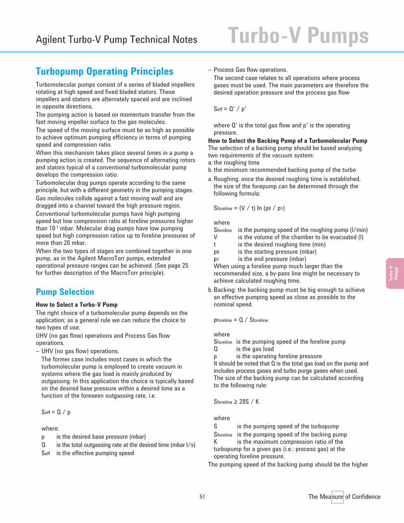
51
Turb
o-V
Pum
ps
Agilent Turbo-V Pump Technical Notes
Turbopump Operating PrinciplesTurbomolecular pumps consist of a series of bladed impellersrotating at high speed and fixed bladed stators. Theseimpellers and stators are alternately spaced and are inclinedin opposite directions.The pumping action is based on momentum transfer from thefast moving impeller surface to the gas molecules.The speed of the moving surface must be as high as possibleto achieve optimum pumping efficiency in terms of pumpingspeed and compression ratio.When this mechanism takes place several times in a pump apumping action is created. The sequence of alternating rotorsand stators typical of a conventional turbomolecular pumpdevelops the compression ratio.Turbomolecular drag pumps operate according to the sameprinciple, but with a different geometry in the pumping stages.Gas molecules collide against a fast moving wall and aredragged into a channel toward the high pressure region.Conventional turbomolecular pumps have high pumpingspeed but low compression ratio at foreline pressures higherthan 10-1 mbar. Molecular drag pumps have low pumpingspeed but high compression ratios up to foreline pressures ofmore than 20 mbar.When the two types of stages are combined together in onepump, as in the Agilent MacroTorr pumps, extendedoperational pressure ranges can be achieved. (See page 25for further description of the MacroTorr principle).
Pump SelectionHow to Select a Turbo-V PumpThe right choice of a turbomolecular pump depends on theapplication; as a general rule we can reduce the choice totwo types of use:UHV (no gas flow) operations and Process Gas flowoperations.– UHV (no gas flow) operations.
The former case includes most cases in which the turbomolecular pump is employed to create vacuum insystems where the gas load is mainly produced byoutgassing. In this application the choice is typically basedon the desired base pressure within a desired time as afunction of the foreseen outgassing rate, i.e.
Seff = Q / p
where:p is the desired base pressure (mbar)Q is the total outgassing rate at the desired time (mbar l/s)Seff is the effective pumping speed
– Process Gas flow operations.The second case relates to all operations where processgases must be used. The main parameters are therefore thedesired operation pressure and the process gas flow
Seff = Q' / p'
where Q' is the total gas flow and p' is the operatingpressure.
How to Select the Backing Pump of a Turbomolecular PumpThe selection of a backing pump should be based analyzingtwo requirements of the vacuum system:a. the roughing time b. the minimum recommended backing pump of the turboa. Roughing: once the desired roughing time is established,
the size of the forepump can be determined through thefollowing formula:
Sforeline = (V / t) ln (p0 / p1)
whereSforeline is the pumping speed of the roughing pump (l/min)V is the volume of the chamber to be evacuated (l)t is the desired roughing time (min)p0 is the starting pressure (mbar)p1 is the end pressure (mbar)When using a foreline pump much larger than therecommended size, a by-pass line might be necessary toachieve calculated roughing time.
b. Backing: the backing pump must be big enough to achievean effective pumping speed as close as possible to thenominal speed.
pforeline = Q / Sforeline
whereSforeline is the pumping speed of the foreline pumpQ is the gas loadp is the operating foreline pressureIt should be noted that Q is the total gas load on the pump andincludes process gases and turbo purge gases when used.The size of the backing pump can be calculated accordingto the following rule:
Sforeline ≥ 20S / K
whereS is the pumping speed of the turbopumpSforeline is the pumping speed of the backing pumpK is the maximum compression ratio of theturbopump for a given gas (i.e.: process gas) at theoperating foreline pressure.
The pumping speed of the backing pump should be the higher
Turbo-V Pumps
Turbo CD2011.qxd:05 Turbo 13-06-2011 18:30 Pagina 51
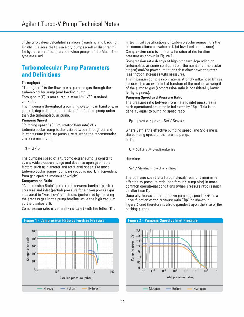
52
of the two values calculated as above (roughing and backing).Finally, it is possible to use a dry pump (scroll or diaphragm)for hydrocarbon-free operation when pumps of the MacroTorrtype are used.
Turbomolecular Pump Parameters and DefinitionsThroughput“Throughput” is the flow rate of pumped gas through theturbomolecular pump (and foreline pump).Throughput (Q) is measured in mbar l/s 1/60 standardcm3/min.The maximum throughput a pumping system can handle is, ingeneral, dependent upon the size of its foreline pump ratherthan the turbomolecular pump.Pumping Speed“Pumping speed” (S) (volumetric flow rate) of aturbomolecular pump is the ratio between throughput andinlet pressure (foreline pump size must be the recommendedone as a minimum).
S = Q / p
The pumping speed of a turbomolecular pump is constantover a wide pressure range and depends upon geometricfactors such as diameter and rotational speed. For mostturbomolecular pumps, pumping speed is nearly independentfrom gas species (molecular weight).Compression Ratio“Compression Ratio” is the ratio between foreline (partial)pressure and inlet (partial) pressure for a given process gas,measured in “zero flow” conditions (performed by injectingthe process gas in the pump foreline while the high vacuumport is blanked off).Compression ratio is generally indicated with the letter “K”.
In technical specifications of turbomolecular pumps, it is themaximum attainable value of K (at low foreline pressure).Compression ratio is, in fact, a function of the forelinepressure as shown in Figure 1.Compression ratio decays at high pressure depending onturbomolecular pump configuration (the number of molecularstages) and/or power limitations that slow down the rotor(gas friction increases with pressure).The maximum compression ratio is strongly influenced by gasspecies: it is an exponential function of the molecular weightof the pumped gas (compression ratio is considerably lowerfor light gases).Pumping Speed and Pressure RatioThe pressure ratio between foreline and inlet pressures ineach operational situation is indicated by “Rp”. This is, ingeneral, equal to pumping speed ratio
Rp = pforeline / pinlet = Seff / Sforeline
where Seff is the effective pumping speed, and Sforeline isthe pumping speed of the foreline pump.In fact
Q = Seff pinlet = Sforeline pforeline
therefore
Seff / Sforeline = pforeline / pinlet
The pumping speed of a turbomolecular pump is minimallyaffected by pressure ratio (and foreline pump size) in mostcommon operational conditions (when pressure ratio is muchsmaller than K).Generally, however, the effective pumping speed “Seff” is alinear function of the pressure ratio “Rp” as shown in Figure 2 (and therefore is also dependent upon the size of thebacking pump).
Inlet pressure (mbar)
200
010-10
Pum
ping
spee
d (l/
s)
10-5 10-4 10-3 10-2 10-1
50
250
150100
1
300350
10-6
Figure 2 - Pumping Speed vs Inlet Pressure
10010
1010
108
106
104
Com
pres
sion
ratio
102
10-2 10-1 1
Foreline pressure (mbar)
1
Figure 1 - Compression Ratio vs Foreline Pressure
Nitrogen Helium Hydrogen Nitrogen Helium Hydrogen
Agilent Turbo-V Pump Technical Notes
Turbo CD2011.qxd:05 Turbo 13-06-2011 18:30 Pagina 52
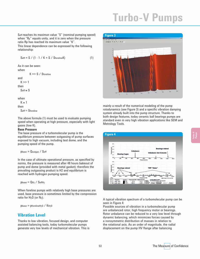
53
Turb
o-V
Pum
ps
Seff reaches its maximun value “S” (nominal pumping speed)when “Rp” equals unity, and it is zero when the pressureratio Rp has reached its maximum value “K”.This linear dependence can be expressed by the followingrelationship:
Seff = S / (1 - 1 / K + S / SforelineK) (1)
As it can be seen:when
K >> S / Sforelineand
K >> 1then
Seff ≅ S
whenK ≅ 1
thenSeff = Sforeline
The above formula (1) must be used to evaluate pumpingspeed when operating at high pressure, especially with lightgases (low K).Base PressureThe base pressure of a turbomolecular pump is theequilibrium pressure between outgassing of pump surfacesexposed to high vacuum, including test dome, and thepumping speed of the pump.
pbase = Qoutgas / Seff
In the case of ultimate operational pressure, as specified bynorms, the pressure is measured after 48 hours bakeout ofpump and dome (provided with metal gasket); therefore theprevailing outgassing product is H2 and equilibrium isreached with hydrogen pumping speed.
pbase = QH2 / SeffH2
When foreline pumps with relatively high base pressures areused, base pressure is sometimes limited by the compressionratio for H2O (or N2).
pbase = pforelineH2O / KH2O
Vibration LevelThanks to low vibration, focused design, and computerassisted balancing tools, today turbomolecular pumpsgenerate very low levels of mechanical vibration. This is
mainly a result of the numerical modeling of the pumprotodynamics (see Figure 3) and a specific vibration dampingsystem already built into the pump structure. Thanks to both design features, today ceramic ball bearings pumps arestandard even in very high vibration applications like SEM andMetrology Tools.
A typical vibration spectrum of a turbomolecular pump can beseen in Figure 4:Possible sources of vibration in a turbomolecular pump are unbalanced rotor, high frequency motor or bearings.Rotor unbalance can be reduced to a very low level throughdynamic balancing, which minimizes forces caused by a nonsymmetric distribution of masses in relation to the rotational axis. As an order of magnitude, the radialdisplacement on the pump HV flange after balancing
Figure 3
Figure 4
Turbo-V Pumps
Turbo CD2011.qxd:05 Turbo 13-06-2011 18:30 Pagina 53

Agilent Turbo-V Pump Technical Notes
54
can be as low as 0.001 µm.The vibrations from a high frequency motor are caused byelectromagnetic interactions between the motor stator androtor: their characteristic frequencies are multiples of themotor driving frequency. Also, the rotor supports generateboth white noise and vibrations at specific frequencies of thebearings’ moving parts (cage, balls and rotating ring, usuallythe inner one). In general, the vibrations caused by an electric motor orbearing are even lower than those caused by unbalance. They may be relevant in the case of bearing damage orbecause of excitation of a natural resonant frequency of thesystem connected to the pump. In the second case,the system structure should be modified by adding mass,changing the stiffness and/or inserting a vibration damperbetween pump and system.
Operation in Presence of Magnetic FieldsMagnetic fields induce eddy currents in the turbomolecularpump rotor that tend to oppose its rotation. As a consequencethe power delivered to the electrical motor is increased.Since the pump rotor is not in contact with the stator, all theheat generated by the eddy currents must be dissipated byradiation, so the rotor can be overheated even if the staticparts remain cool.According to our tests, the maximum magnetic field that ourpumps can tolerate is:• 50 Gauss in the transversal direction• 100 Gauss in the axial directionIn these cases, a power increase to the motor can be expected.If the magnetic field is greater than the above values a shieldmust be used in order to have a residual magnetic fieldaround the pump below the value specified.Please contact Agilent for more details.
Electrical InterfacingThe input/output of our controllers have been designed togive maximum flexibility to operate the pump remotely.Two types of interface are offered for the following twocontroller families:• Rack controllers (including V 81, V 301, V 550, V 700HT,
V 1000HT)• Navigator controllers (including V 301, V 551, V 701,
V 1001)Please contact Agilent for more details.
Turbomolecular Pump Bearings and Lubrication SystemThe Turbo-V pumps incorporate Agilent’s innovative ceramicbearing design with a proprietary ultra-low vapor pressure
solid lubricant, which enables these pumps to provide a longservice life and a high degree of cleanliness under mostoperating conditions. This lubrication system is a superiorfeature of Agilent Technology and guarantees nocontamination of the vacuum system, especially whencompared to other oil-lubricated turbomolecular pumps (Seefigures 5-6).The ceramic bearings utilize balls made of silicon nitride, apolycrystalline material with an amorphous intergranularbinder base that offers the following advantages:Hardness This is a critical aspect of bearing design, and it closely relates to bearing performance and reliability. The siliconnitride material used in Agilent’s Turbo-V bearing system istwice as hard as conventional steel providing dramaticimprovement in wear resistance while minimizing the effectsof surface contact and stress.Weight Silicon nitride is 40% less dense than conventional steels,which helps to reduce centrifugal loading and stress levels athigh rotational speeds, especially in the bearing race area.
1
H2
10-8
10-9
10-10
10-11
10-1216116
H2O
21 26 31 36 41 46 51 56 61 66 71 76 81 86a.m.u.
N2
O2
CO2
CF2C3F CF3
C5F
P (To
rr)
Figure 5 - Typical Competitor Pump
1 11
H2
10-9
10-10
10-11
10-12166
H2O
21 26 31 36 41 46 51 56 61 66 71 76 81 86a.m.u.
N2
O2 CO2
P (T
orr)
Figure 6 - Typical Agilent Pump
Turbo CD2011.qxd:05 Turbo 13-06-2011 18:30 Pagina 54
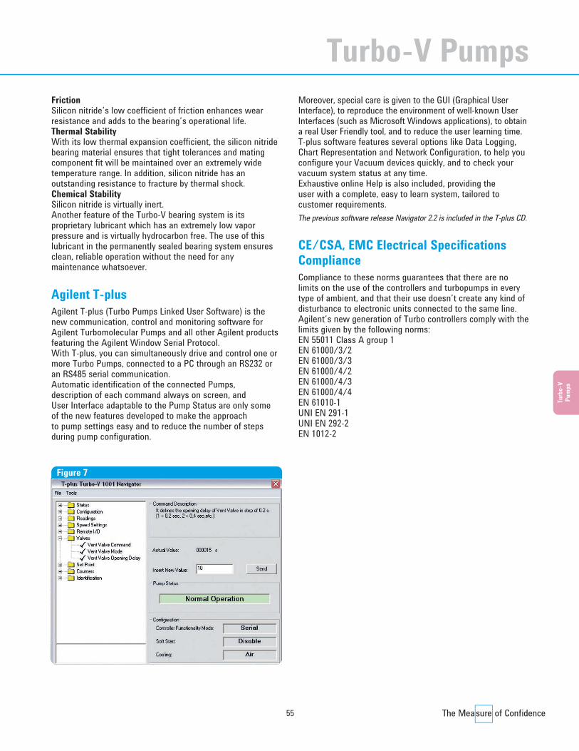
55
Turb
o-V
Pum
ps
Friction Silicon nitride’s low coefficient of friction enhances wearresistance and adds to the bearing’s operational life.Thermal Stability With its low thermal expansion coefficient, the silicon nitridebearing material ensures that tight tolerances and matingcomponent fit will be maintained over an extremely widetemperature range. In addition, silicon nitride has anoutstanding resistance to fracture by thermal shock.Chemical Stability Silicon nitride is virtually inert.Another feature of the Turbo-V bearing system is itsproprietary lubricant which has an extremely low vaporpressure and is virtually hydrocarbon free. The use of thislubricant in the permanently sealed bearing system ensuresclean, reliable operation without the need for anymaintenance whatsoever.
Agilent T-plusAgilent T-plus (Turbo Pumps Linked User Software) is thenew communication, control and monitoring software forAgilent Turbomolecular Pumps and all other Agilent productsfeaturing the Agilent Window Serial Protocol.With T-plus, you can simultaneously drive and control one ormore Turbo Pumps, connected to a PC through an RS232 oran RS485 serial communication.Automatic identification of the connected Pumps, description of each command always on screen, and User Interface adaptable to the Pump Status are only some of the new features developed to make the approach to pump settings easy and to reduce the number of stepsduring pump configuration.
Moreover, special care is given to the GUI (Graphical UserInterface), to reproduce the environment of well-known UserInterfaces (such as Microsoft Windows applications), to obtaina real User Friendly tool, and to reduce the user learning time.T-plus software features several options like Data Logging,Chart Representation and Network Configuration, to help youconfigure your Vacuum devices quickly, and to check yourvacuum system status at any time.Exhaustive online Help is also included, providing the user with a complete, easy to learn system, tailored tocustomer requirements.The previous software release Navigator 2.2 is included in the T-plus CD.
CE/CSA, EMC Electrical SpecificationsComplianceCompliance to these norms guarantees that there are nolimits on the use of the controllers and turbopumps in everytype of ambient, and that their use doesn’t create any kind ofdisturbance to electronic units connected to the same line.Agilent’s new generation of Turbo controllers comply with thelimits given by the following norms:EN 55011 Class A group 1EN 61000/3/2EN 61000/3/3EN 61000/4/2EN 61000/4/3EN 61000/4/4EN 61010-1UNI EN 291-1UNI EN 292-2EN 1012-2
Figure 7
Turbo-V Pumps
Turbo CD2011.qxd:05 Turbo 13-06-2011 18:30 Pagina 55

Agilent Turbo Pump Service and Support Plans
56
Agilent Vacuum Products offers one of the mostcomprehensive service and support plans in the industry.As a worldwide, first class company we strive to offer addedvalue to our Customers wherever they may be located.Excellence in Service and Support is a key factor in added value.Support can be accomplished with qualified Engineers and anappropriate logistic infrastructure.Technical skills and infrastructure are two areas where weare continuously making medium and long-term investments.Our daily customer support philosophy is focused on twoimportant factors: fast response and no hassle.This philosophy translates to the following sections of ourTurbo Pump Service and Support Plan:• Worldwide Parts Sourcing Plan:
Three Progressive Levels of Support• Technical Assistance: Customer Support, Application
Support, Application Training• Uptime Services: Remote DiagnosticsAgilent Vacuum Products is committed to providing ourCustomers with the most comprehensive service plans possible.The following pages detail the standard sections of our TurboPump Service and Support Plan. For more information, or ifyou have a need for customized solutions, please contactyour Agilent representative.Often, excellent products are not enough: Agilent’s constantpresence with Customer Service as a responsive partner iswhat really makes a difference.
Worldwide Parts Sourcing Plan• Repair Program
Agilent products offer unmatched reliability, performanceand cleanliness. Production requirements, however,inevitably create, over time, the need for maintenance andrepair. Timely repair at Agilent will keep your productsperforming at an outstanding level all the time.
• Advanced Exchange ProgramTo maximize uptime, and for those occasions where time isessential, Agilent offers exchange units for advanceshipment.Exchange units are fully remanufactured to the same strictstandards as new products. They are kept in stock in NorthAmerica, Europe, China, Japan, Korea, Singapore andTaiwan.As soon as requested, your Exchange unit can be shippedfor overnight delivery. This efficiency is due to our logisticinfrastructure and is the result of excellent teamworkamong our Service and Customer Service Teams!The Exchange and Repair Programs are available worldwideand allow global OEMs and End-Users consistent deliverytime, value pricing, consistent part numbers, and simpleorder processing procedures.Ordering Information for Agilent’s Exchange ProgramTo order an Exchange unit, add the letters “EX” before theproduct part number you need to exchange.After receipt of the exchange unit, you have 20 days to shipthe original unit back to Agilent. To place your request,contact the closest Agilent location.
• Upgrade ProgramThe Upgrade Program is designed for customers who need toreplace an Agilent (formerly Varian) product at the end of itslife, or of old technology, with a newest technology product. For example, a customer may wish to replace a Turbo-V250with our Turbo-V301 Navigator.
Turbo CD2011.qxd:05 Turbo 13-06-2011 18:30 Pagina 56
57
The Upgrade Program includes proactive technicalinstallation support, by telephone and full 12-monthwarranty.Agilent’s Turbo pump Upgrade Program provides acustomer with the same outstanding support delivered withour service programs, including:- RMA# tracking- Replacement with remanufactured pump of the newest
technology- Advance replacement- 24-hour expedited order management- WEB on-line order status & shipment tracking
• End User Extended WarrantyThe End User Extended Warranty is a Service Agreementthat provides coverage extension beyond the standard 12months warranty of a product. It extends for additional 12months the coverage from failures due to defects inmaterial and workmanship.By extending the warranty of purchased products,post-sales satisfaction is guaranteed. This is the result ofthe relevant cost decrease while cost predictability isincreased.The End User Extended Warranty has been designed tocover the needs of the End User Market:- General Purpose Vacuum applications.- High Energy Physics Ultra High Vacuum applications.
Ordering Information for End User Extended Warranty
General Purpose Vacuum Applications Part NumberExtd. Warranty 12M Turbo 80 l/s class EW81Extd. Warranty 12M Turbo 300 l/s class EW300Extd. Warranty 12M Turbo 700 l/s class EW700Extd. Warranty 12M Turbo 1000 l/s class EW1000Extd. Warranty 12M Turbo TV1KG EWTV1KGExtd. Warranty 12M Turbo TV2KG EWTV2KGExtd. Warranty 12M Turbo TV3KG EWTV3KGExtd. Warranty 12M Turbo (other config.) EW969TMPHigh Energy Physics UHV Applications Part NumberExtd. Warranty HEP 12M Turbo 80 l/s class EW969TV81Extd. Warranty HEP 12M Turbo 300 l/s class EW969TV301Extd. Warranty HEP 12M Turbo 700 l/s class EW969TV701Extd. Warranty HEP 12M Turbo 1000 l/s class EW969TV1001Extd. Warranty HEP 12M Turbo V2300 EW969TV2300Extd. Warranty 12M Turbo (other config.) EW969TMP
• Cleaning ServiceAgilent offers a cleaning service in cases where a turbo pump may have been exposed to chemicallyhazardous materials.This service is available worldwide and allows global OEMsand End-Users consistent delivery time, pricing, partnumbers, and order processing procedures.Ordering Information for Agilent’s Cleaning Service
Turbo-V Pump Size Part NumberFrom V 60 to V 301 Navigator TURBOCLEAN1From V 450 to V 701 Navigator TURBOCLEAN2From V 1000 to TV 3K-G TURBOCLEAN3
Turb
o-V
Pum
ps
Turbo-V Pumps
Turbo CD2011.qxd:05 Turbo 13-06-2011 18:30 Pagina 57
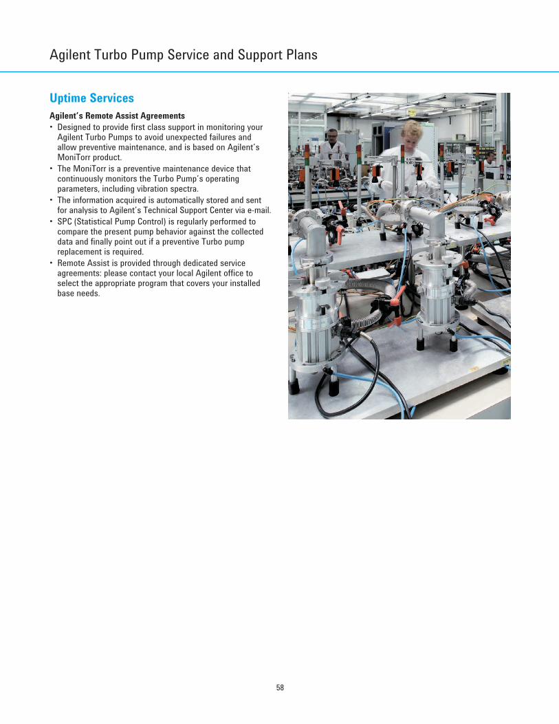
Agilent Turbo Pump Service and Support Plans
58
Uptime ServicesAgilent’s Remote Assist Agreements• Designed to provide first class support in monitoring your
Agilent Turbo Pumps to avoid unexpected failures andallow preventive maintenance, and is based on Agilent’sMoniTorr product.
• The MoniTorr is a preventive maintenance device thatcontinuously monitors the Turbo Pump’s operatingparameters, including vibration spectra.
• The information acquired is automatically stored and sentfor analysis to Agilent’s Technical Support Center via e-mail.
• SPC (Statistical Pump Control) is regularly performed tocompare the present pump behavior against the collecteddata and finally point out if a preventive Turbo pumpreplacement is required.
• Remote Assist is provided through dedicated serviceagreements: please contact your local Agilent office toselect the appropriate program that covers your installedbase needs.
Turbo CD2011.qxd:05 Turbo 13-06-2011 18:30 Pagina 58
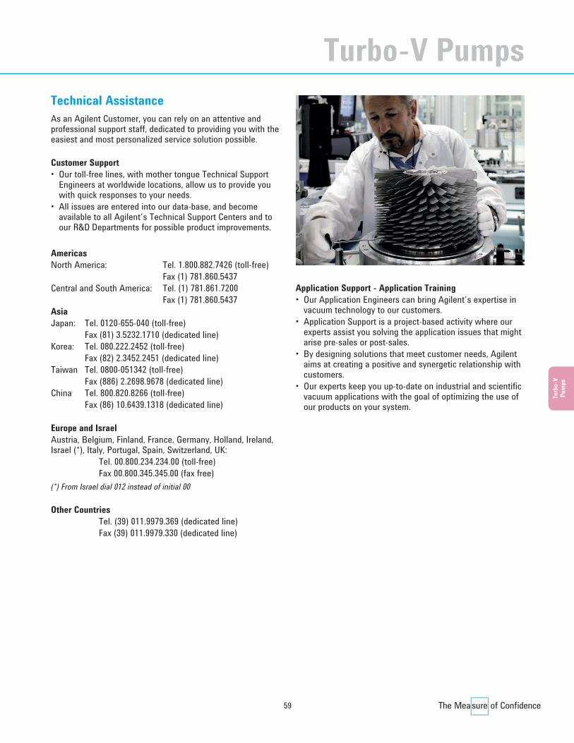
59
Technical AssistanceAs an Agilent Customer, you can rely on an attentive andprofessional support staff, dedicated to providing you with theeasiest and most personalized service solution possible.
Customer Support• Our toll-free lines, with mother tongue Technical Support
Engineers at worldwide locations, allow us to provide youwith quick responses to your needs.
• All issues are entered into our data-base, and becomeavailable to all Agilent’s Technical Support Centers and toour R&D Departments for possible product improvements.
AmericasNorth America: Tel. 1.800.882.7426 (toll-free)
Fax (1) 781.860.5437Central and South America: Tel. (1) 781.861.7200
Fax (1) 781.860.5437AsiaJapan: Tel. 0120-655-040 (toll-free)
Fax (81) 3.5232.1710 (dedicated line)Korea: Tel. 080.222.2452 (toll-free)
Fax (82) 2.3452.2451 (dedicated line)Taiwan Tel. 0800-051342 (toll-free)
Fax (886) 2.2698.9678 (dedicated line)China Tel. 800.820.8266 (toll-free)
Fax (86) 10.6439.1318 (dedicated line)
Europe and IsraelAustria, Belgium, Finland, France, Germany, Holland, Ireland,Israel (*), Italy, Portugal, Spain, Switzerland, UK:
Tel. 00.800.234.234.00 (toll-free)Fax 00.800.345.345.00 (fax free)
(*) From Israel dial 012 instead of initial 00
Other CountriesTel. (39) 011.9979.369 (dedicated line)Fax (39) 011.9979.330 (dedicated line)
Application Support - Application Training• Our Application Engineers can bring Agilent’s expertise in
vacuum technology to our customers.• Application Support is a project-based activity where our
experts assist you solving the application issues that mightarise pre-sales or post-sales.
• By designing solutions that meet customer needs, Agilentaims at creating a positive and synergetic relationship withcustomers.
• Our experts keep you up-to-date on industrial and scientificvacuum applications with the goal of optimizing the use ofour products on your system.
Turb
o-V
Pum
ps
Turbo-V Pumps
Turbo CD2011.qxd:05 Turbo 13-06-2011 18:30 Pagina 59