Agilent N1022A Active Probe Adapter User · PDF fileTechnology Licenses ... Torque the...
24
Agilent N1022A Active Probe Adapter User Guide
Transcript of Agilent N1022A Active Probe Adapter User · PDF fileTechnology Licenses ... Torque the...
Agilent N1022AActive Probe AdapterUser Guide
ii
Notices© Agilent Technologies, Inc. 2003
No part of this manual may be repro-duced in any form or by any means (including electronic storage and retrieval or translation into a foreign lan-guage) without prior agreement and writ-ten consent from Agilent Technologies, Inc. as governed by United States and international copyright lays.
Manual Part Number
N1022-90001
Edition
First edition, April 2003
Printed in USA
Agilent Technologies, Inc.Lightwave Division1400 Fountaingrove ParkwaySanta Rosa, CA 95403, USA
Warranty
The material contained in this document is provided “as is,” and is subject to being changed, without notice, in future edi-tions. Further, to the maximum extent permitted by applicable law, Agilent dis-claims all warranties, either express or implied, with regard to this manual and any information contained herein, includ-ing but not limited to the implied warran-ties of merchantability and fitness for a particular purpose. Agilent shall not be liable for errors or for incidental or conse-quential damages in connection with the furnishing, use, or performance of this document or of any information con-tained herein. Should Agilent and the user have a separate written agreement with warranty terms covering the mate-rial in this document that conflict with these terms, the warranty terms in the separate agreement shall control.
Technology Licenses
The hardware and/or software described in this document are furnished under a license and may be used or copied only in accordance with the terms of such license.
Restricted Rights Legend
If software is for use in the performance of a U.S. Government prime contract or subcontract, Software is delivered and licensed as “Commercial computer soft-ware” as defined in DFAR 252.227-7014 (June 1995), or as a “commercial item” as defined in FAR 2.101(a) or as “Restricted computer software” as defined in FAR 52.227-19 (June 1987) or any equivalent agency regulation or contract clause. Use, duplication or disclosure of Software is subject to Agilent Technologies’ standard commercial license terms, and non-DOD Departments and Agencies of the U.S. Government will receive no greater than Restricted Rights as defined in FAR 52.227-19(c)(1-2) (June 1987). U.S. Gov-ernment users will receive no greater than Limited Rights as defined in FAR 52.227-14 (June 1987) or DFAR 252.227-7015 (b)(2) (November 1995), as appli-cable in any technical data.
Safety Notices
CAUTIONCaution denotes a hazard. It calls attention to a procedure which, if not correctly per-formed or adhered to, could result in damage to or destruction of the product. Do not proceed beyond a caution sign until the indicated conditions are fully understood and met.
WARNINGWarning denotes a hazard. It calls attention to a procedure which, if not correctly per-formed or adhered to, could result in injury or loss of life. Do not proceed beyond a warning sign until the indicated conditions are fully understood and met.
Contents
Contents 1
N1022A Active Probe Adapter 1
General Safety Considerations 2Instrument Markings 3
Using the Probe Adapter 4
Inspecting the N1022A 4Connecting the N1022A 5
Static-Safe Workstation 8
Reducing ESD Damage 9
Specifications and Regulatory Information 10
Specifications 10Regulatory Information 13Declaration of Conformity 14
Service 15
Checking Probe Power Outputs 15Returning the N1022A 16Agilent Technologies Service Offices 17

Contents 2
Contents

1
N1022A Active Probe Adapter
N1022A Active Probe Adapter
The N1022A Active Probe Adapter provides the interface to connect an Agilent Infiniimax Active Probe to an Agilent 86100-series Infiniium DCA. To use the N1022A requires that firmware revision A.03.05 or later be installed on the Infiniium DCA.
The Infiniimax Active Probes include the following: 1131A, 1132A, and 1134A.
Other supported active probes include the 1152A, 1156A, 1157A, and 1158A.
C A U T I O N When using the N1022A, always work at a static-safe work station and wear a wrist-strap or heel-strap. Refer to “Static-Safe Workstation” on page 8.
C A U T I O N The probe adapter connections can be damaged if it is dropped from excessive heights onto a hard surface.
2
General Safety Considerations
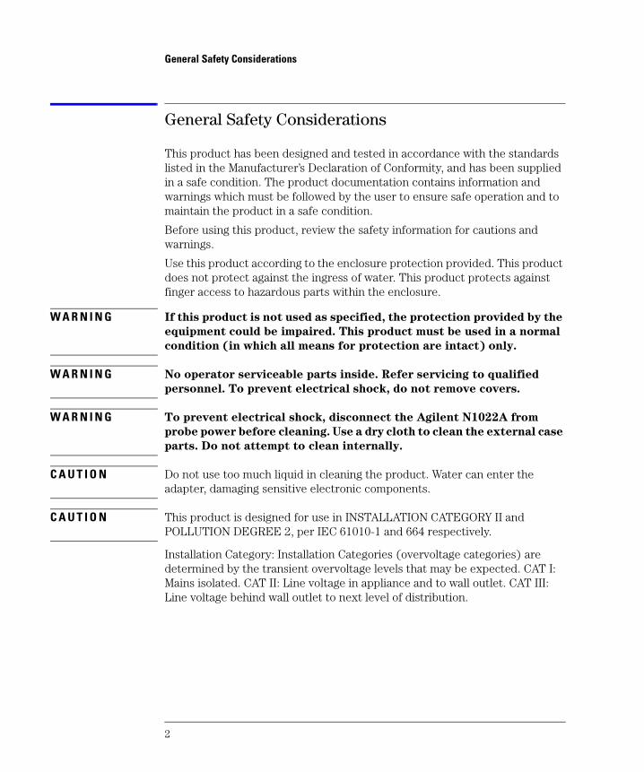
General Safety Considerations
This product has been designed and tested in accordance with the standards listed in the Manufacturer’s Declaration of Conformity, and has been supplied in a safe condition. The product documentation contains information and warnings which must be followed by the user to ensure safe operation and to maintain the product in a safe condition.
Before using this product, review the safety information for cautions and warnings.
Use this product according to the enclosure protection provided. This product does not protect against the ingress of water. This product protects against finger access to hazardous parts within the enclosure.
W A R N I N G If this product is not used as specified, the protection provided by the
equipment could be impaired. This product must be used in a normal
condition (in which all means for protection are intact) only.
W A R N I N G No operator serviceable parts inside. Refer servicing to qualified
personnel. To prevent electrical shock, do not remove covers.
W A R N I N G To prevent electrical shock, disconnect the Agilent N1022A from
probe power before cleaning. Use a dry cloth to clean the external case
parts. Do not attempt to clean internally.
C A U T I O N Do not use too much liquid in cleaning the product. Water can enter the adapter, damaging sensitive electronic components.
C A U T I O N This product is designed for use in INSTALLATION CATEGORY II and POLLUTION DEGREE 2, per IEC 61010-1 and 664 respectively.
Installation Category: Installation Categories (overvoltage categories) are determined by the transient overvoltage levels that may be expected. CAT I: Mains isolated. CAT II: Line voltage in appliance and to wall outlet. CAT III: Line voltage behind wall outlet to next level of distribution.

3
Instrument Markings
Instrument Markings
The instruction manual symbol. The product is marked with this warning symbol when it is necessary for the user to refer to the instructions in the manual.
The laser radiation symbol. This warning symbol is marked on prod-ucts which have a laser output.
The AC symbol is used to indicate the required nature of the line module input power.
The Standby symbol is used to mark the position of the instrument power line switch.
The CE mark is a registered trademark of the European Commu-nity.
The CSA mark is a registered trademark of the Canadian Standards Association.
The C-Tick mark is a registered trademark of the Australian Spec-trum Management Agency.
This text denotes the instrument is an Industrial Scientific and Medical Group 1 Class A product.
This text indicates product compliance with the Canadian Interference-Causing Equipment Standard.
ISM1-A
ICES/NMB-001

4
Using the Probe Adapter
Using the Probe Adapter
There are a few things to consider when connecting the N1022A Active Probe Adapter to an active probe and the Infiniium DCA.
• The dynamic range of the system will be 3.2 V (6.4 Vp-p), which with probe off-set, covers most digital technologies.
• The Infiniium DCA provides both power and offset control to the active probe adapter through the plug-in module front panel connector.
• Probe offset is changed by adjusting the vertical offset control located on the plug-in module front panel. The control should be adjusted to center your sig-nal within the 5V peak-to-peak (12 volts peak-to-peak for slow signals) dynam-ic range of the probe.
Available
Accessories
The following accessory is available from Agilent.
8 in-lbs torque wrench: . . . . . . . . . . . . . . . . . . . . . . . . . . . . . . . . P/N 8710-1764
Cleaning the
N1022A
If the probe adapter requires cleaning, disconnect it from both the instrument and the probe. Wipe with a soft cloth dampened with a mild soap and water solution. Make sure the adapter is completely dry before reconnecting to the probe and instrument.
Inspecting the N1022A
Inspect the shipping container for damage.
Keep a damaged shipping container or cushioning material until the contents of the shipment have been checked for completeness and the probe adapter has been checked mechanically and electrically.
Inspect the probe adapter.
• If there is mechanical damage or defect, or if the probe adapter does not operate properly or pass performance tests, notify your Agilent

5
Connecting the N1022A
Technologies sales office.
• If the shipping container is damaged, or the cushioning materials show signs of stress, notify the carrier as well as your Agilent Technologies sales office. Keep the shipping materials for the carrier's inspection. The Agilent office will arrange for replacement of the N1022A at Agilent’s option without waiting for claim settlement.
Connecting the N1022A
C A U T I O N When using the N1022A, always work at a static-safe work station and wear a wrist-strap or heel-strap. Refer to “Static-Safe Workstation” on page 8. Electrical channel input circuits can be damaged by electrostatic discharge (ESD). Therefore, avoid applying static discharges to the front-panel input connectors. Avoid touching the front-panel input connectors without first touching the frame of the instrument. Be sure that the instrument is properly earth-grounded to prevent buildup of static charge.
1 Connect the N1022A probe adapter to the module’s electrical input connector. This requires holding the N1022A connector steady while turning the module’s input connector. This action threads the module’s connector into the N1022A’s connector. Torque the connection to 8 in-lbs. An 8 in-lbs torque wrench is available from Agilent. Order part number 8710-1764.
C A U T I O N To ensure a good connection and to avoid damaging the connectors, tighten the connection to 8 in-lbs of torque. After the adapter is connected, do not allow the adapter to rotate on the front-panel connection. For more information on caring for precision electrical connectors, refer to the online help that is accessed from the 86100B Infiniium DCA’s menu bar.
2 Connect the probe adapter’s power connector to the module’s front-panel Probe Power connector for the associated channel. Do not make the connection to any Aux Power connector, if one is present on the module’s front
Using modules with 2.4 mm electrical input
The N1022A can be directly connected to any 86100-series or 83480-series with a 3.5 mm electrical channel input. You can also connect the probe adapter to a module with 2.4 mm electrical input. However, in order to connect to a 2.4 mm input, you must use a 2.4 mm(F) - 3.5 mm (M) adapter, Agilent part number 85130-60010.
6
Connecting the N1022A
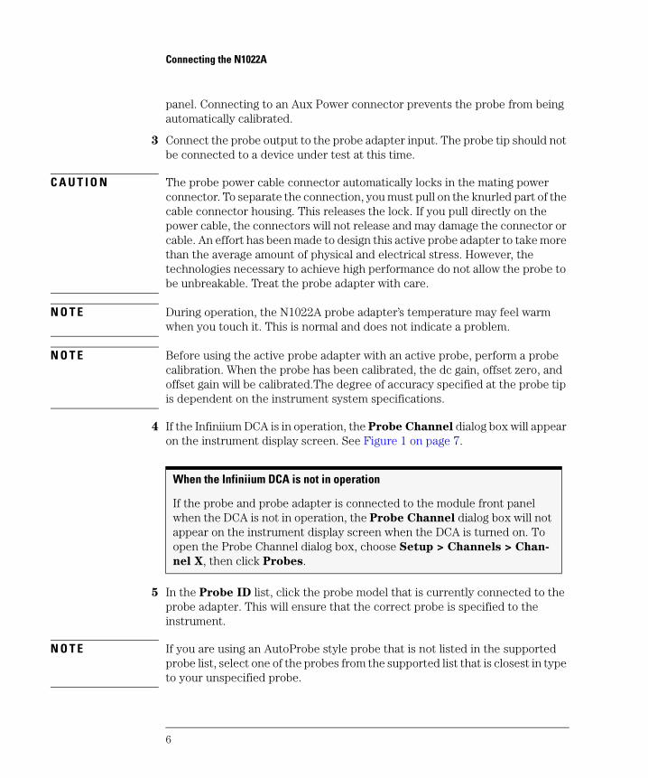
panel. Connecting to an Aux Power connector prevents the probe from being automatically calibrated.
3 Connect the probe output to the probe adapter input. The probe tip should not be connected to a device under test at this time.
C A U T I O N The probe power cable connector automatically locks in the mating power connector. To separate the connection, you must pull on the knurled part of the cable connector housing. This releases the lock. If you pull directly on the power cable, the connectors will not release and may damage the connector or cable. An effort has been made to design this active probe adapter to take more than the average amount of physical and electrical stress. However, the technologies necessary to achieve high performance do not allow the probe to be unbreakable. Treat the probe adapter with care.
N O T E During operation, the N1022A probe adapter’s temperature may feel warm when you touch it. This is normal and does not indicate a problem.
N O T E Before using the active probe adapter with an active probe, perform a probe calibration. When the probe has been calibrated, the dc gain, offset zero, and offset gain will be calibrated.The degree of accuracy specified at the probe tip is dependent on the instrument system specifications.
4 If the Infiniium DCA is in operation, the Probe Channel dialog box will appear on the instrument display screen. See Figure 1 on page 7.
5 In the Probe ID list, click the probe model that is currently connected to the probe adapter. This will ensure that the correct probe is specified to the instrument.
N O T E If you are using an AutoProbe style probe that is not listed in the supported probe list, select one of the probes from the supported list that is closest in type to your unspecified probe.
When the Infiniium DCA is not in operation
If the probe and probe adapter is connected to the module front panel when the DCA is not in operation, the Probe Channel dialog box will not appear on the instrument display screen when the DCA is turned on. To open the Probe Channel dialog box, choose Setup > Channels > Chan-
nel X, then click Probes.
7
Connecting the N1022A
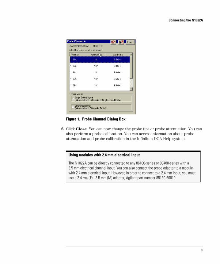
Figure 1. Probe Channel Dialog Box
6 Click Close. You can now change the probe tips or probe attenuation. You can also perform a probe calibration. You can access information about probe attenuation and probe calibration in the Infiniium DCA Help system.
Using modules with 2.4 mm electrical input
The N1022A can be directly connected to any 86100-series or 83480-series with a 3.5 mm electrical channel input. You can also connect the probe adapter to a module with 2.4 mm electrical input. However, in order to connect to a 2.4 mm input, you must use a 2.4 mm(F) - 3.5 mm (M) adapter, Agilent part number 85130-60010.

8
Static-Safe Workstation
Static-Safe Workstation
Electrostatic discharge (ESD) can damage or destroy electronic components. All work on electronic assemblies should be performed at a static-safe work-station. The following figure shows an example of a static-safe work station using two types of ESD protection:
• Conductive table-mat and wrist-strap combination.
• Conductive floor-mat and heel-strap combination.
Figure 2. Static Safe Workstation
9
Reducing ESD Damage
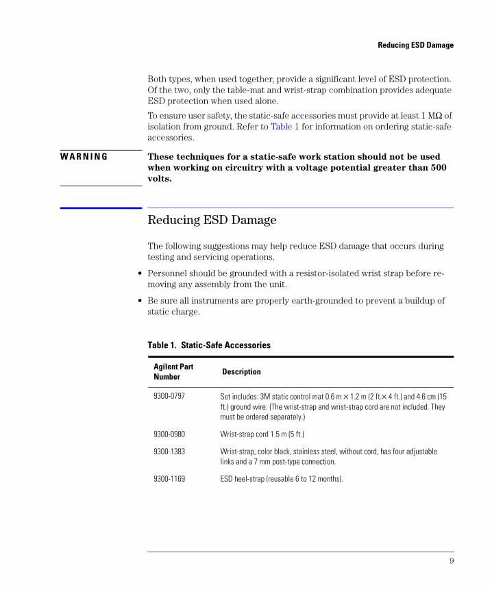
Both types, when used together, provide a significant level of ESD protection. Of the two, only the table-mat and wrist-strap combination provides adequate ESD protection when used alone.
To ensure user safety, the static-safe accessories must provide at least 1 MΩ of isolation from ground. Refer to Table 1 for information on ordering static-safe accessories.
W A R N I N G These techniques for a static-safe work station should not be used
when working on circuitry with a voltage potential greater than 500
volts.
Reducing ESD Damage
The following suggestions may help reduce ESD damage that occurs during testing and servicing operations.
• Personnel should be grounded with a resistor-isolated wrist strap before re-moving any assembly from the unit.
• Be sure all instruments are properly earth-grounded to prevent a buildup of static charge.
Table 1. Static-Safe Accessories
Agilent Part Number
Description
9300-0797 Set includes: 3M static control mat 0.6 m × 1.2 m (2 ft.× 4 ft.) and 4.6 cm (15 ft.) ground wire. (The wrist-strap and wrist-strap cord are not included. They must be ordered separately.)
9300-0980 Wrist-strap cord 1.5 m (5 ft.)
9300-1383 Wrist-strap, color black, stainless steel, without cord, has four adjustable links and a 7 mm post-type connection.
9300-1169 ESD heel-strap (reusable 6 to 12 months).

10
Specifications and Regulatory Information
Specifications and Regulatory Information
This section lists specifications and characteristics and regulatory information of the probe adapter.
Specifications
The distinction between specifications and characteristics is described as fol-lows:
• Specifications describe warranted performance over the temperature range 0°C to +55°C and relative humidity <95% (unless otherwise noted). All specifications apply after the temperature of the probe and the probe adapter has been stabilized after 30 minutes of continuous operation.
• Characteristics provide useful information by giving functional, but nonwarranted, performance parameters. Characteristics are printed in
italics.
Review the following specifications to ensure that your operating or storage environment is suitable for the adapter.
Table 2. Environmental Specifications (1 of 2)
Operating Temperature 0° C to +55°C
Storage Temperature –40° C to +70°C
Use Indoor
EMC Conducted and radiatedEmission is in compliance with CISPR 11 Class Aand IEC 61326
ESD Tolerance 4kV contact 8kV air discharged
Operational Humidity (type tested) 95% R.H. (non-condensing) at +40°C (+104°F)
Altitude Up to 4600 meters
11
Specifications
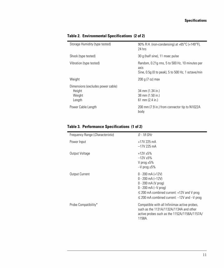
Storage Humidity (type tested) 90% R.H. (non-condensing) at +65°C (+149°F),24 hrs
Shock (type tested) 30 g (half sine), 11 msec pulse
Vibration (type tested) Random, 0.21g rms, 5 to 500 Hz, 10 minutes per axisSine, 0.5g (0 to peak), 5 to 500 Hz, 1 octave/min
Weight 200 g (7 oz) max
Dimensions (excludes power cable)HeightWeightLength
34 mm (1.34 in.)38 mm (1.50 in.)61 mm (2.4 in.)
Power Cable Length 200 mm (7.9 in.) from connector tip to N1022A body
Table 3. Performance Specifications (1 of 2)
Frequency Range (Characteristic) 0 - 18 GHz
Power Input +17V 225 mA–17V 225 mA
Output Voltage +12V ±5%–12V ±5%V prog ±5%–V prog ±5%
Output Current 0 - 200 mA (+12V)0 - 200 mA (–12V)0 - 200 mA (V prog)0 - 200 mA (–V prog)≤ 200 mA combined current: +12V and V prog≤ 200 mA combined current: –12V and –V prog
Probe Compatibility* Compatible with all Infiniimax active probes, such as the 1131A/1132A/1134A and other active probes such as the 1152A/1156A/1157A/1158A.
Table 2. Environmental Specifications (2 of 2)
12
Specifications
*Other Infiniium instruments in compliance with the Autoprobe interface can be added using the Probe dialog box located in the Infiniium graphical user interface.
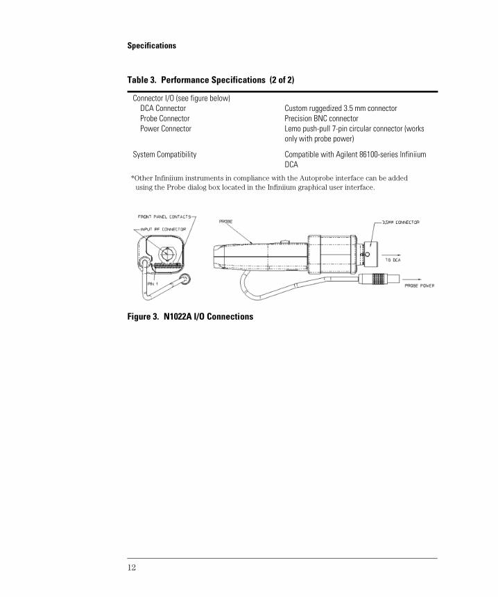
Figure 3. N1022A I/O Connections
Connector I/O (see figure below)DCA ConnectorProbe ConnectorPower Connector
Custom ruggedized 3.5 mm connectorPrecision BNC connectorLemo push-pull 7-pin circular connector (works only with probe power)
System Compatibility Compatible with Agilent 86100-series Infiniium DCA
Table 3. Performance Specifications (2 of 2)

13
Regulatory Information
Regulatory Information
Electrostatic Discharge Immunity - IEC 61000-4-2: 1995 passes criterion B.
According to IEC 61000-4-2: 1995, system measurement may be affected when electrostatic discharges of 2 kV or more are applied to the outer sur-faces of the N1022A probe adapter when it is connected as part of a measure-ment system.
Compliance with
Canadian EMC
Requirements
This ISM device complies with Canadian ICES-001.
Cet appareil ISM est conforme a la norme NMB du Canada.
Compliance with
German Noise
Requirements
This is to declare that this instrument is in conformance with the German Reg-ulation on Noise Declaration for Machines (Laermangabe nach der Maschinen-laermrerordnung -3.GSGV Deutschland).
Table 4. Notice for Germany: Noise Declaration
Acoustic Noise Emission Geraeuschemission
LpA < 70 dB LpA < 70 dB
Operator position am Arbeitsplatz
Normal position normaler Betrieb
per ISO 7779 nach DIN 45635 t.19
14
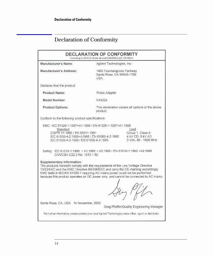
Declaration of Conformity
Declaration of Conformity
15
Service
Service
Service for the N1022A Active Probe Adapter is by replacement only. To order a new N1022A, contact your local Agilent Technologies Sales Office. Return the failed probe adapter to your local Agilent service center.
If the probe adapter is still under warranty or is covered by an Agilent mainte-nance contract, it will be replaced under the terms of the warranty or con-tract.
Refer to “Agilent Technologies Service Offices” on page 17 to contact the Agi-lent Call Center or your local service center.
Checking Probe Power Outputs
The probe power output is located on the front panel of the probe adapter, surrounding the BNC input.
Use Table 5 on page 16 to check the power output at the connectors. The DCA module provides the probe adapter with +17V and -17V supplies. The probe adapter generates the +12 V and -12 V supplies and the +3 V and -3 V sup-plies.
Measure the voltages with respect to the DCA mainframe’s front panel ground connector (located above the power switch) or the outside conductor of the Cal BNC connector.
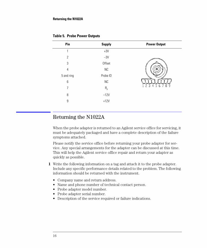
C A U T I O N Do not attempt to measure voltages at pins 3 through 7.
Any failure may be a problem with the probe adapter assembly.
16
Returning the N1022A
Returning the N1022A
When the probe adapter is returned to an Agilent service office for servicing, it must be adequately packaged and have a complete description of the failure symptoms attached.
Please notify the service office before returning your probe adapter for ser-vice. Any special arrangements for the adapter can be discussed at this time. This will help the Agilent service office repair and return your adapter as quickly as possible.
1 Write the following information on a tag and attach it to the probe adapter. Include any specific performance details related to the problem. The following information should be returned with the instrument.
• Company name and return address. • Name and phone number of technical contact person. • Probe adapter model number. • Probe adapter serial number. • Description of the service required or failure indications.
Table 5. Probe Power Outputs
Pin Supply Power Output
1 +3V
2 –3V
3 Offset
4 NC
5 and ring Probe ID
6 NC
7 RP
8 –12V
9 +12V

17
Agilent Technologies Service Offices
C A U T I O N Cover electrical connectors to protect sensitive components from electrostatic damage.
C A U T I O N Use original packaging or comparable. Instrument damage can result from using packaging materials other than the original materials. Never use styrene pellets as packaging material. They do not adequately cushion the instrument or prevent it from shifting in the carton. They may also cause instrument damage by generating static electricity.
2 Return the probe adapter in its case or pack the adapter in foam or other shock absorbing material and place it in a strong shipping container.
3 Seal the shipping container securely.
4 In all correspondence, refer to the probe adapter by model number and full serial number.
5 Retain copies of all shipping papers.
Agilent Technologies Service Offices
Call Center For technical assistance, you can contact your local Agilent Technologies Call Center.
• In the Americas, call 1 (800) 452-4844
• In other regions, visit http://www.agilent.com and click Contact Us.
Service Center Before returning an instrument for service, you must first call the Agilent Technologies Instrument Support Center.
• In all regions, call (800) 403-0801

18
Agilent Technologies Service Offices

Index
Index 1
AAccessories, 4Agilent offices, 17
CCE mark, 3cleaning, 2, 4, 17CSA mark, 3
DDeclaration of Conformity, 14
EEMC requirements, 13environmental specifications, 10ESD
reducing damage caused by ESD, 9static-safe work station, 9
Iinspecting, 4ISM1-A, 3
Nnoise declaration, 13noise requirements, 13
Pperformance specifications, 11probe power outputs, 15
Ssales and service offices, 17service
returning the probe adapter, 16sales and service offices, 17service and replaceable parts, 15
specificationsenvironmental, 10performance, 11
Ttemperature, 6torque wrench, 4
Uusing, 4

Index 2
Index