Agilent Haim S
54
Analog X-parameters at the System-Level Haim Spiegel EEsof Israel Accurate and Convenient tools to achieve RF-BB and ESL-RF design flow closure December 9, 2010 Haim Spiegel 1
description
EEsof
Transcript of Agilent Haim S
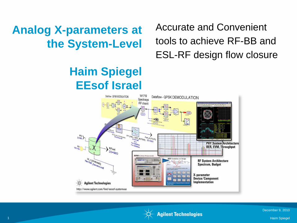
Analog X-parameters at the System-Level
Haim SpiegelEEsof Israel
Accurate and Convenienttools to achieve RF-BB andESL-RF design flow closure
December 9, 2010
Haim Spiegel1
Outline
Problem Statement: The RF-Baseband Design Gap
What are X-parameters?
How can X-parameters fit into System-Level Tools?– Tools Used : Agilent EEsof ADS and SystemVue
Case study Based on Power Amplifier X Parameter model1. QPSK Modulation2. Radar Example3. Tunable Non-Linear Notch Filter4. Digital Predistortion
December 9, 2010
Haim Spiegel2
Problem Statement : The RF-Baseband Design Gap
Traditional BB tools for communications algorithm and digital signal processing do not account well for
– RF models, RF effects, Measurements, Wireless and specialized IP
Dedicated RF tools do not easily support baseband algorithm and hardware development
Need a creation tool that helps with RF-Baseband cross-domainarchitectures, diagnostics, and partitioning :
– “Where is the least expensive place to solve a particular problem?” – “What is the root cause of link-level performance issues?”– “What is my actual design margin?”
December 9, 2010
Haim Spiegel3
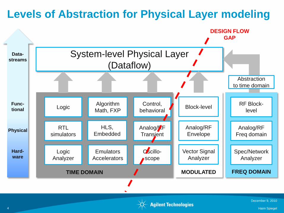
Levels of Abstraction for Physical Layer modeling
December 9, 2010
Haim Spiegel4
System-level Physical Layer(Dataflow)
RTL simulators
Analog/RFEnvelope
Analog/RFTransient
TIME DOMAIN
Analog/RFFreq domain
Logic Analyzer
Vector Signal Analyzer
Oscillo-scope
Spec/Network Analyzer
MODULATED FREQ DOMAIN
EmulatorsAccelerators
Abstraction to time domain
Logic Block-levelControl, behavioral
RF Block-level
DESIGN FLOW GAP
AlgorithmMath, FXP
HLS, Embedded
Hard-ware
Physical
Func-tional
Data-streams

SystemVue: a cross-domain, ESL approach
December 9, 2010
Haim Spiegel5
System-level Physical Layer(Dataflow)
RTL simulators
Analog/RFEnvelope
Analog/RFTransient
TIME DOMAIN
Analog/RFFreq domain
Logic Analyzer
Vector Signal Analyzer
Oscillo-scope
Spec/Network Analyzer
MODULATED FREQ DOMAIN
EmulatorsAccelerators
Abstraction to time domain
Logic Block-levelAlgorithmMath, FXP
Control, behavioral
RF Block-level
Hard-ware
Physical
Func-tional
Data-streams
THIS PRESENTATIONSystemVue
HLS, Embedded
Outline
What are X-parameters?
Extraction and Verification
How can X-parameters fit into System-Level tools?
6
Haim Spiegel
December 9, 2010
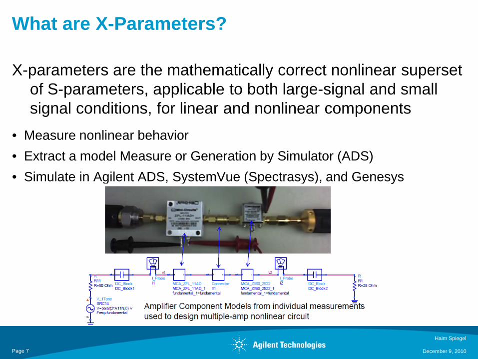
What are X-Parameters?
X-parameters are the mathematically correct nonlinear superset of S-parameters, applicable to both large-signal and small signal conditions, for linear and nonlinear components
• Measure nonlinear behavior• Extract a model Measure or Generation by Simulator (ADS)• Simulate in Agilent ADS, SystemVue (Spectrasys), and Genesys
Haim Spiegel
December 9, 2010Page 7

X-parameters come from the Poly-Harmonic Distortion (PHD) Framework
8
Haim Spiegel
December 9, 2010
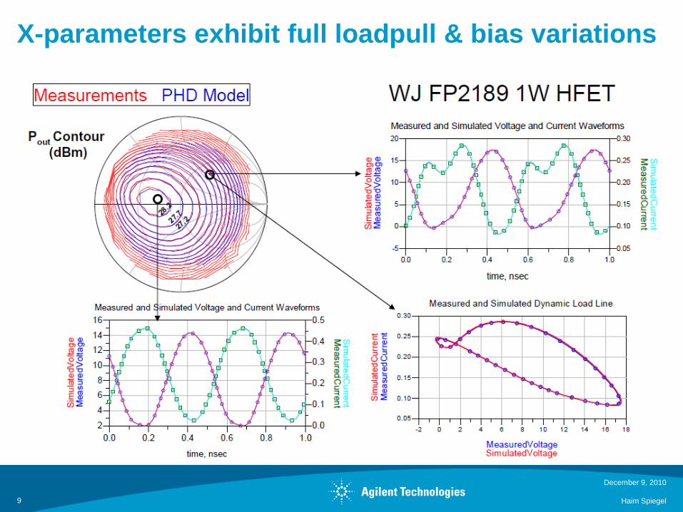
X-parameters exhibit full loadpull & bias variations
December 9, 2010
Haim Spiegel9
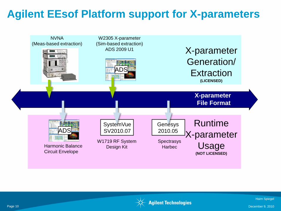
Agilent EEsof Platform support for X-parameters
NVNA(Meas-based extraction)
W2305 X-parameter (Sim-based extraction)
ADS 2009 U1
ADS
Harmonic BalanceCircuit Envelope
RuntimeX-parameter
Usage(NOT LICENSED)
X-parameterGeneration/Extraction
(LICENSED)
X-parameter File Format
ADSGenesys2010.05
SpectrasysHarbec
SystemVueSV2010.07
W1719 RF System Design Kit
December 9, 2010Page 10
Haim Spiegel
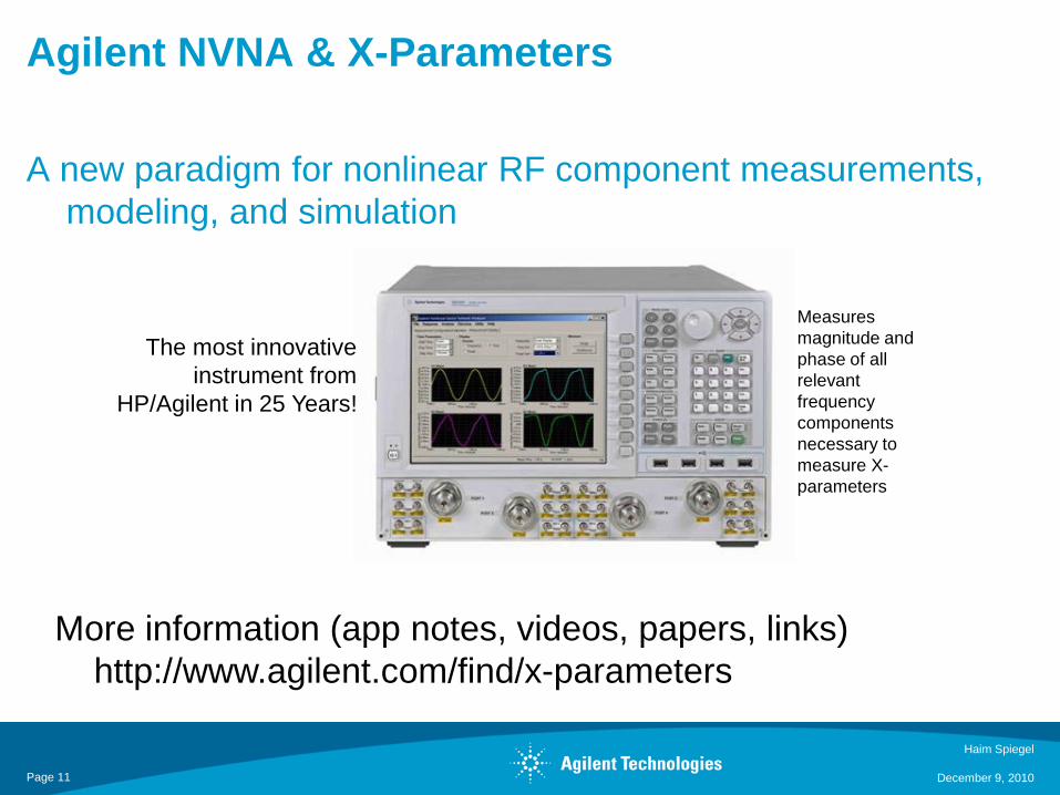
Agilent NVNA & X-Parameters
A new paradigm for nonlinear RF component measurements, modeling, and simulation
The most innovative instrument from
HP/Agilent in 25 Years!
Measures magnitude and phase of all relevant frequency components necessary to measure X-parameters
More information (app notes, videos, papers, links)http://www.agilent.com/find/x-parameters
December 9, 2010Page 11
Haim Spiegel

Outline
• Power Amplifier
December 9, 2010
Haim Spiegel12
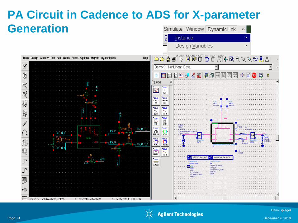
PA Circuit in Cadence to ADS for X-parameter Generation
Haim Spiegel
December 9, 2010Page 13
Haim Spiegel
December 9, 2010
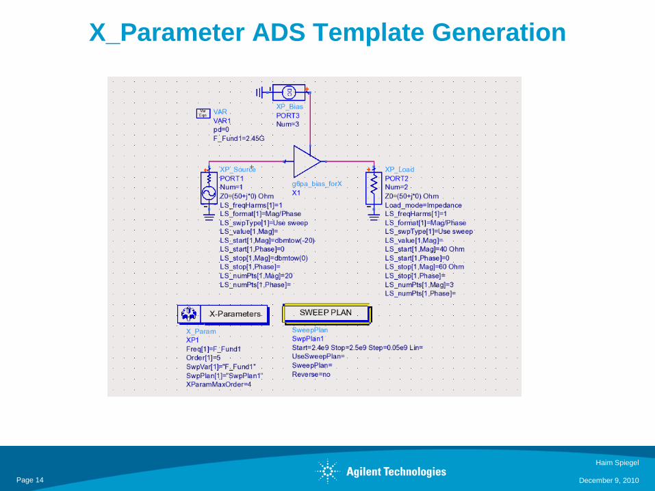
X_Parameter ADS Template Generation
Page 14

X_Parameter File
Haim Spiegel
December 9, 2010Page 15
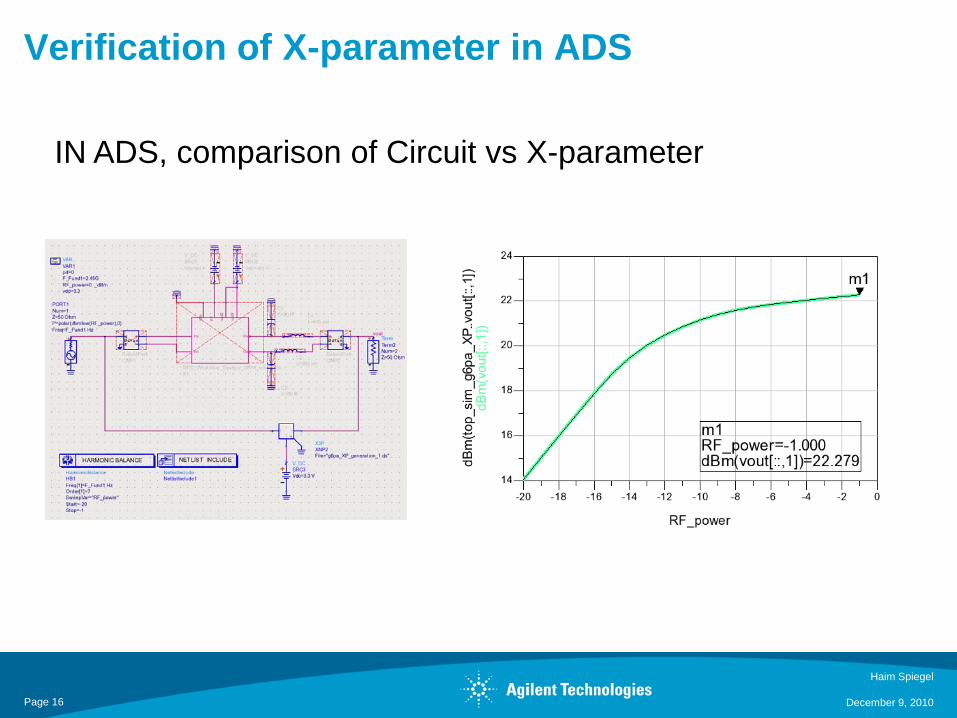
Verification of X-parameter in ADS
Haim Spiegel
December 9, 2010
IN ADS, comparison of Circuit vs X-parameter
Page 16
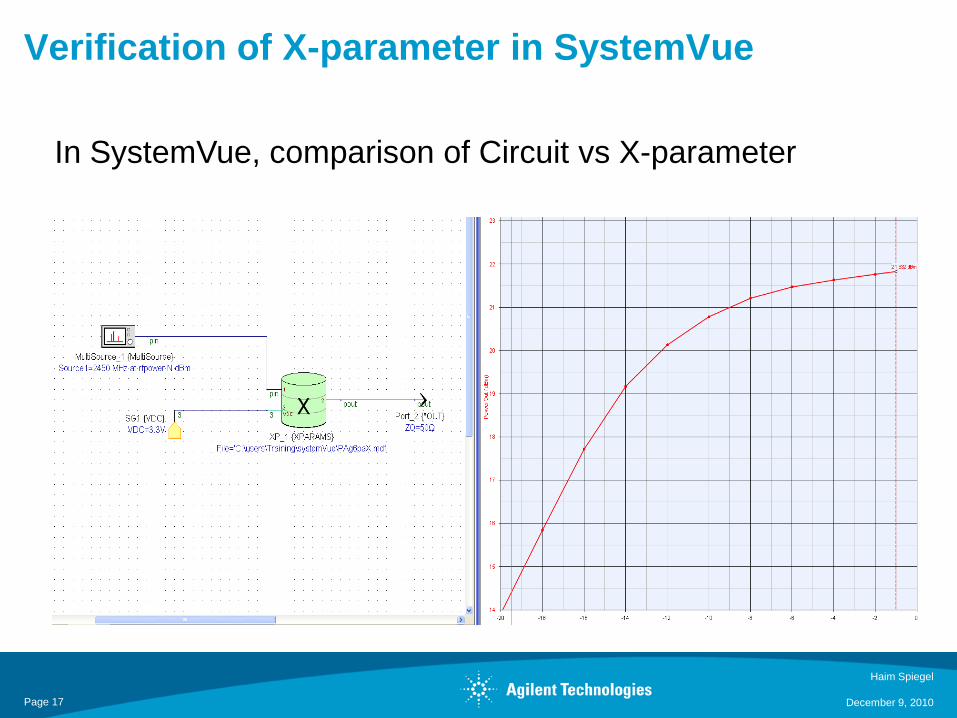
Verification of X-parameter in SystemVue
Haim Spiegel
December 9, 2010
In SystemVue, comparison of Circuit vs X-parameter
Page 17
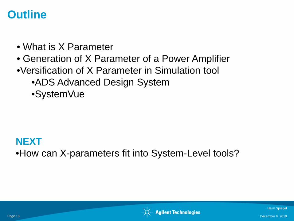
Outline
Haim Spiegel
December 9, 2010
• What is X Parameter• Generation of X Parameter of a Power Amplifier•Versification of X Parameter in Simulation tool
•ADS Advanced Design System•SystemVue
Page 18
NEXT •How can X-parameters fit into System-Level tools?

How can X-parameters fit into System-Level tools?
1-DSP and RF X-parameter Simulation SetupIn SystemVue
Haim Spiegel
December 9, 2010Page 19
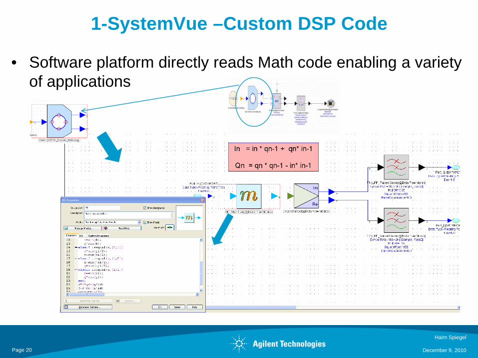
1-SystemVue –Custom DSP Code
• Software platform directly reads Math code enabling a variety of applications
Haim Spiegel
December 9, 2010Page 20
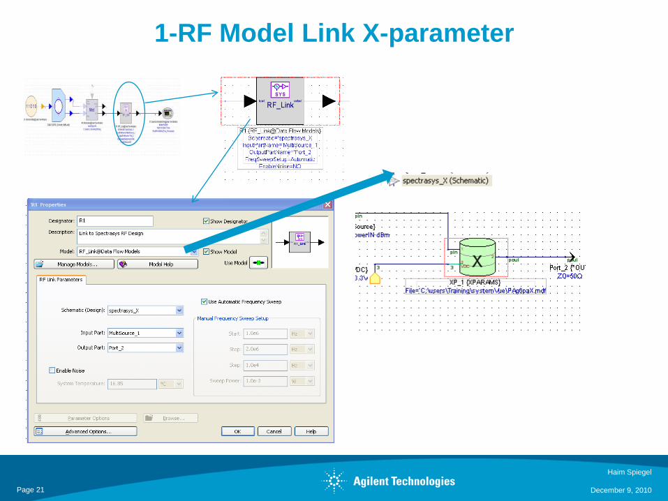
1-RF Model Link X-parameter
Haim Spiegel
December 9, 2010Page 21
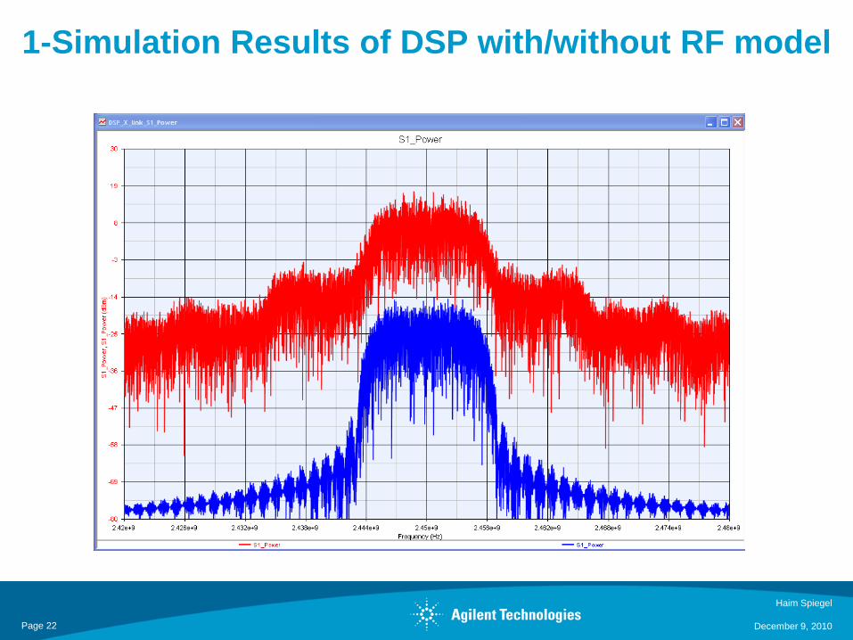
1-Simulation Results of DSP with/without RF model
Haim Spiegel
December 9, 2010Page 22
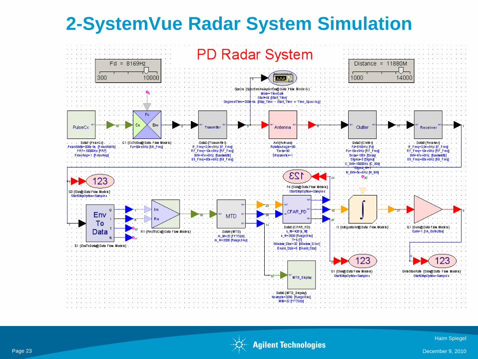
2-SystemVue Radar System Simulation
Haim Spiegel
December 9, 2010Page 23
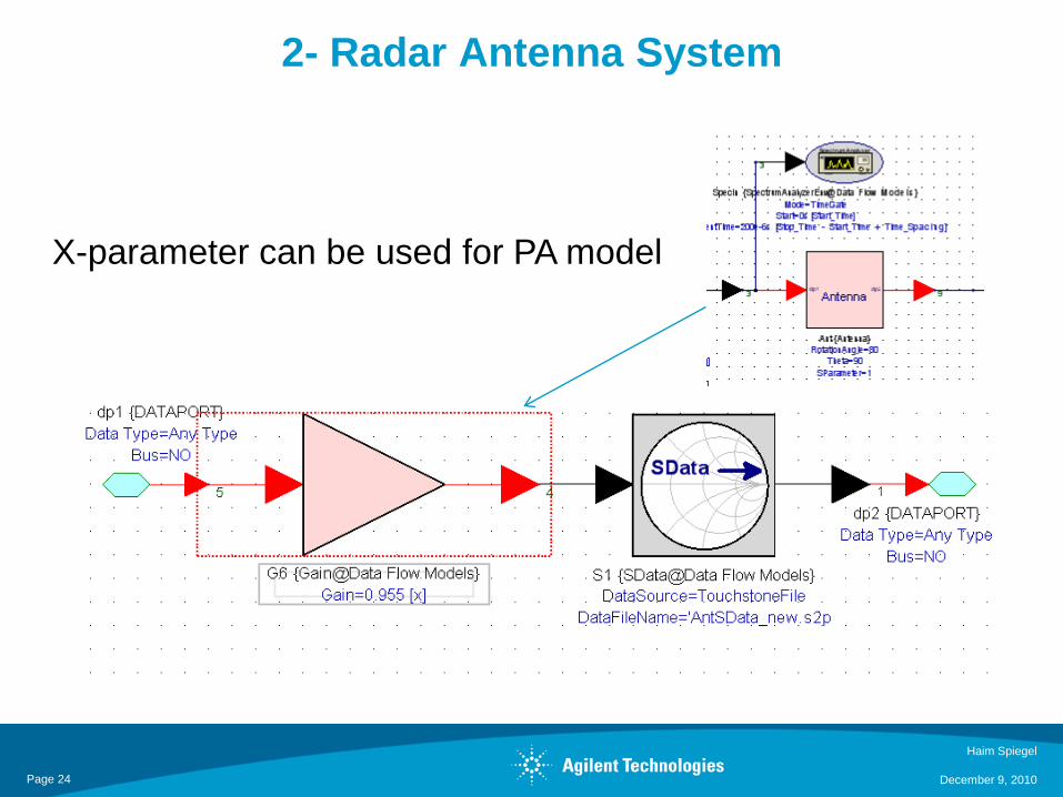
2- Radar Antenna System
Haim Spiegel
December 9, 2010
X-parameter can be used for PA model
Page 24
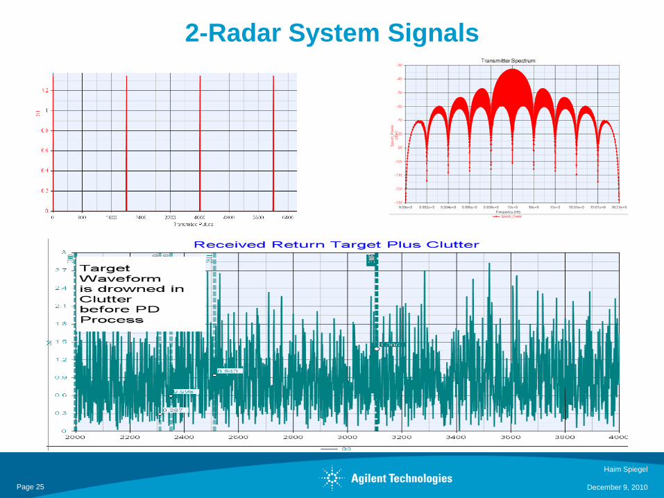
2-Radar System Signals
Haim Spiegel
December 9, 2010Page 25
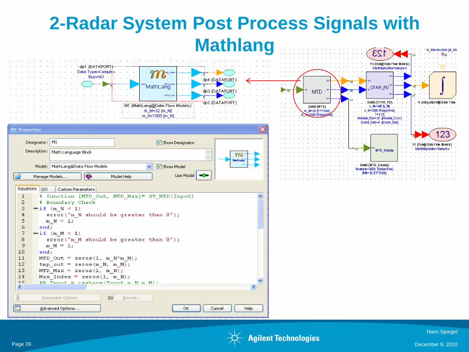
2-Radar System Post Process Signals with Mathlang
MTD
Haim Spiegel
December 9, 2010Page 26
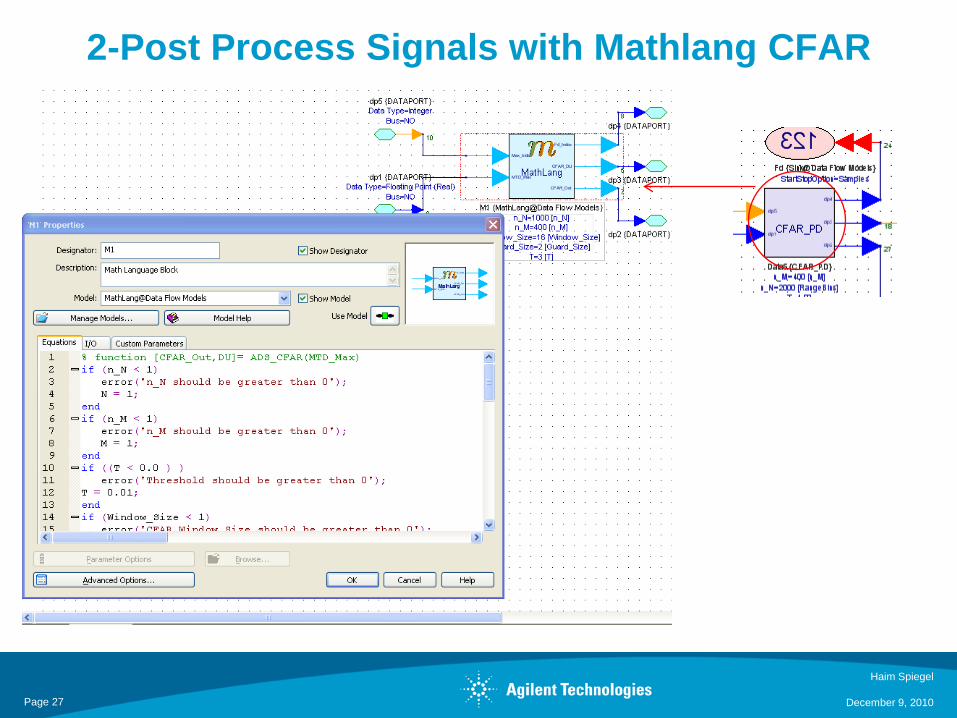
2-Post Process Signals with Mathlang CFAR
Haim Spiegel
December 9, 2010Page 27
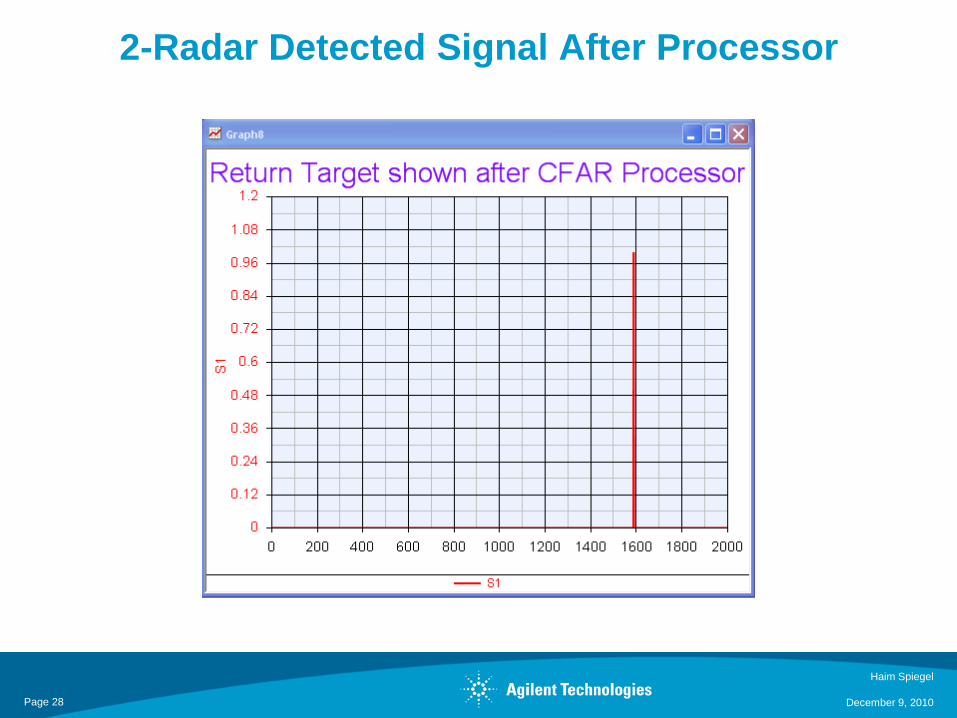
2-Radar Detected Signal After Processor
Haim Spiegel
December 9, 2010Page 28
Outline
NEXT3. Tunable Non-Linear Notch Filter
December 9, 2010
Haim Spiegel29
• What is X Parameter• Generation of X Parameter of a Power Amplifier•Versification of X Parameter in Simulation tool
•ADS Advanced Design System•SystemVue
•How can X-parameters fit into System-Level tools.•QPSK example
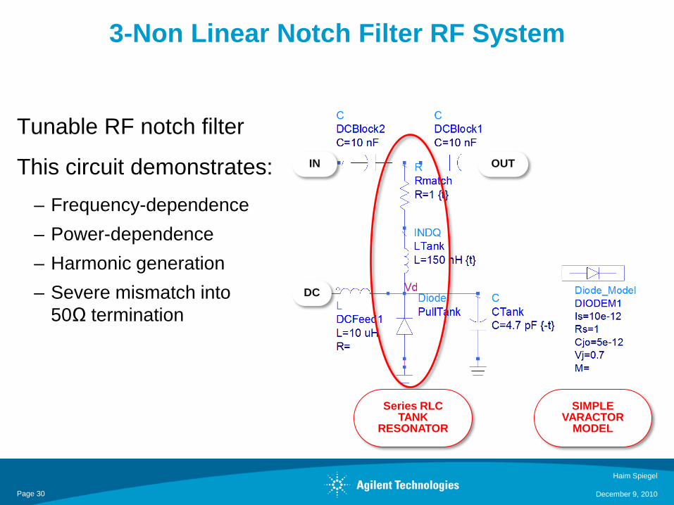
3-Non Linear Notch Filter RF System
Haim Spiegel
December 9, 2010
Tunable RF notch filter
This circuit demonstrates: – Frequency-dependence– Power-dependence– Harmonic generation– Severe mismatch into
50Ω termination
Series RLCTANK
RESONATOR
SIMPLE VARACTOR
MODEL
DC
IN OUT
Page 30
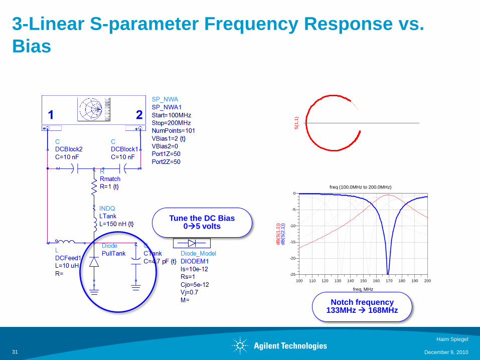
3-Linear S-parameter Frequency Response vs. Bias
31
110 120 130 140 150 160 170 180 190100 200
-20
-15
-10
-5
-25
0
freq, MHzdB
(S(2
,1))
dB(S
(1,1
))
freq (100.0MHz to 200.0MHz)
S(1,
1)
Tune the DC Bias05 volts
Notch frequency 133MHz 168MHz
Haim Spiegel
December 9, 2010
3-Nonlinear performance (using harmonic balance)HB simulation must be set up before the X-parameter extraction
32
Fundfreq=dBm(Vout)=-2.370
145.0MHzH2ind Delta=dep Delta=-42.340Delta Mode ON
1.450E8
0.2 0.4 0.6 0.8 1.0 1.20.0 1.4
-90
-80
-70
-60
-50
-40
-30
-20
-10
-100
0
freq, GHz
dBm
(Vou
t)
Fund
H2
Fundfreq=dBm(Vout)=-2.370
145.0MHzH2ind Delta=dep Delta=-42.340Delta Mode ON
1.450E8
2 4 6 8 10 120 14
-0.8
-0.6
-0.4
-0.2
0.0
0.2
0.4
0.6
0.8
-1.0
1.0
time, nsec
ts(V
out),
V
STARTS FORWARD BIASING AT APPROX+10dBm INPUT PWR
MILDLY NONLINEARAT +0 dBm INPUT PWR
THE NOTCH FREQUENCY TUNES AWAY FROM NONIMAL AT HIGHER POWER LEVELS…how much?
Haim Spiegel
December 9, 2010
Pin=0dBm
Pin=-20dBm
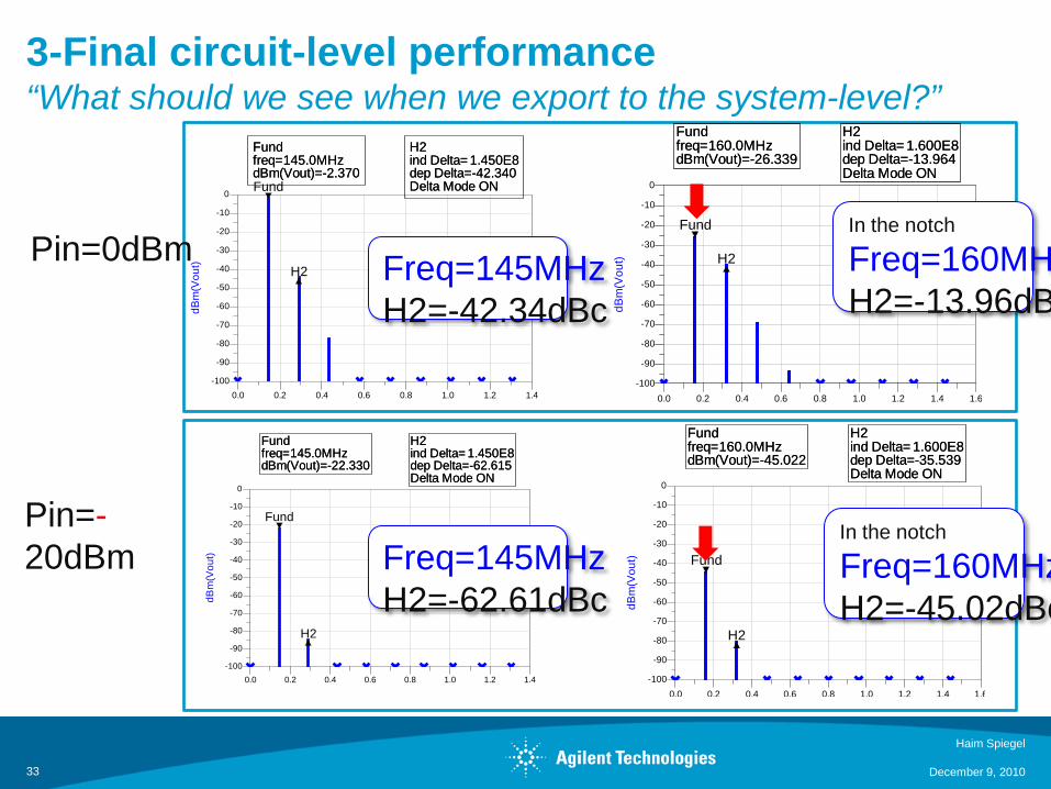
3-Final circuit-level performance“What should we see when we export to the system-level?”
33
Fundfreq=dBm(Vout)=-2.370
145.0MHzH2ind Delta=dep Delta=-42.340Delta Mode ON
1.450E8
0.2 0.4 0.6 0.8 1.0 1.20.0 1.4
-90
-80
-70
-60
-50
-40
-30
-20
-10
-100
0
dBm
(Vou
t)Fund
H2
Fundfreq=dBm(Vout)=-2.370
145.0MHzH2ind Delta=dep Delta=-42.340Delta Mode ON
1.450E8
Fundfreq=dBm(Vout)=-26.339
160.0MHzH2ind Delta=dep Delta=-13.964Delta Mode ON
1.600E8
0.2 0.4 0.6 0.8 1.0 1.2 1.40.0 1.6
-90
-80
-70
-60
-50
-40
-30
-20
-10
-100
0
dBm
(Vou
t)
Fund
H2
Fundfreq=dBm(Vout)=-26.339
160.0MHzH2ind Delta=dep Delta=-13.964Delta Mode ON
1.600E8
Fundfreq=dBm(Vout)=-45.022
160.0MHzH2ind Delta=dep Delta=-35.539Delta Mode ON
1.600E8
0.2 0.4 0.6 0.8 1.0 1.2 1.40.0 1.6
-90
-80
-70
-60
-50
-40
-30
-20
-10
-100
0
dBm
(Vou
t) Fund
H2
Fundfreq=dBm(Vout)=-45.022
160.0MHzH2ind Delta=dep Delta=-35.539Delta Mode ON
1.600E8Fundfreq=dBm(Vout)=-22.330
145.0MHzH2ind Delta=dep Delta=-62.615Delta Mode ON
1.450E8
0.2 0.4 0.6 0.8 1.0 1.20.0 1.4
-90
-80
-70
-60
-50
-40
-30
-20
-10
-100
0
dBm
(Vou
t)
Fund
H2
Fundfreq=dBm(Vout)=-22.330
145.0MHzH2ind Delta=dep Delta=-62.615Delta Mode ON
1.450E8
Freq=145MHzH2=-42.34dBc
Freq=145MHzH2=-62.61dBc
In the notch
Freq=160MHH2=-13.96dB
In the notch
Freq=160MHzH2=-45.02dBc
Haim Spiegel
December 9, 2010
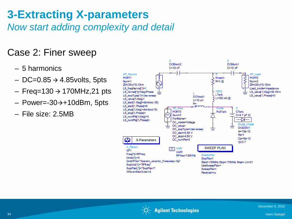
3-Extracting X-parametersNow start adding complexity and detail
Case 2: Finer sweep– 5 harmonics– DC=0.85 4.85volts, 5pts– Freq=130 170MHz,21 pts– Power=-30+10dBm, 5pts– File size: 2.5MB
December 9, 2010
Haim Spiegel34
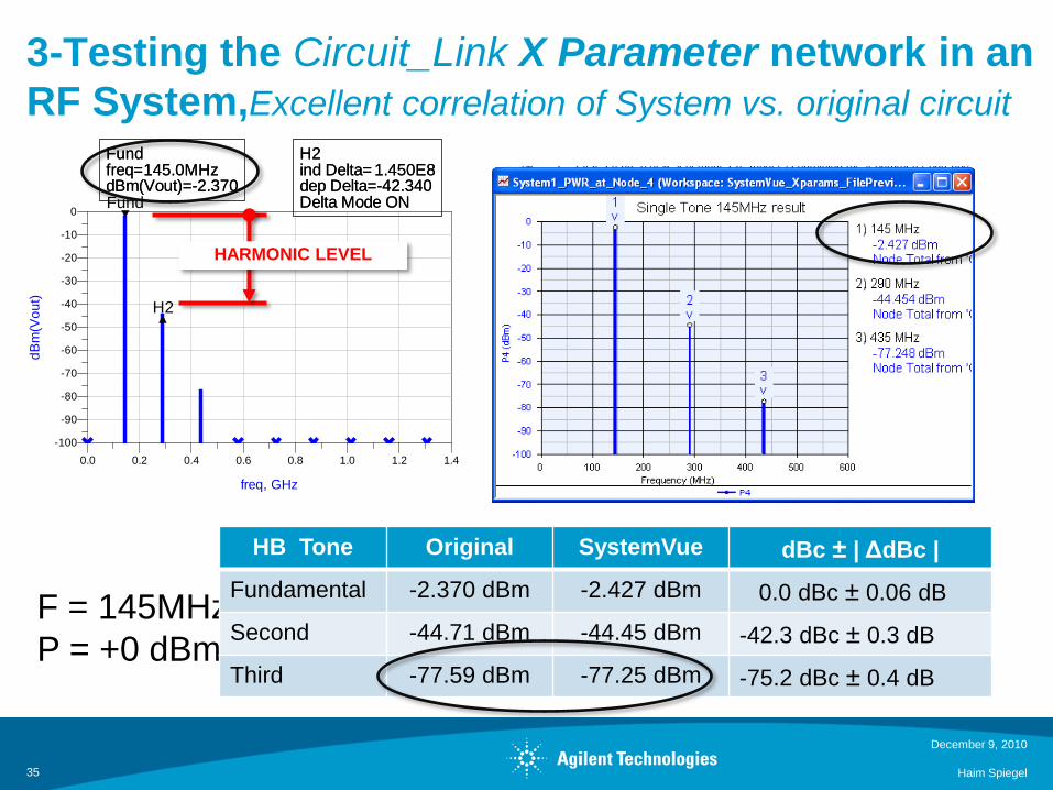
3-Testing the Circuit_Link X Parameter network in an RF System,Excellent correlation of System vs. original circuit
December 9, 2010
Haim Spiegel35
Fundfreq=dBm(Vout)=-2.370
145.0MHzH2ind Delta=dep Delta=-42.340Delta Mode ON
1.450E8
0.2 0.4 0.6 0.8 1.0 1.20.0 1.4
-90
-80
-70
-60
-50
-40
-30
-20
-10
-100
0
freq, GHz
dBm
(Vou
t)
Fund
H2
Fundfreq=dBm(Vout)=-2.370
145.0MHzH2ind Delta=dep Delta=-42.340Delta Mode ON
1.450E8
HARMONIC LEVEL
F = 145MHzP = +0 dBm
HB Tone Original SystemVue dBc ± | ΔdBc | Fundamental -2.370 dBm -2.427 dBm 0.0 dBc ± 0.06 dB
Second -44.71 dBm -44.45 dBm -42.3 dBc ± 0.3 dB
Third -77.59 dBm -77.25 dBm -75.2 dBc ± 0.4 dB
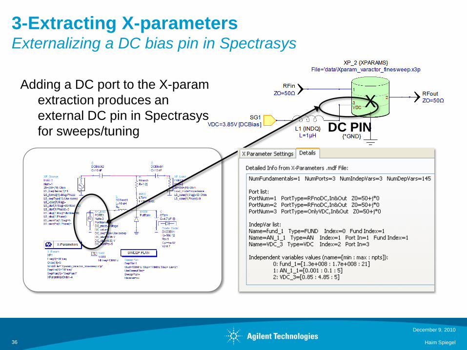
3-Extracting X-parametersExternalizing a DC bias pin in Spectrasys
December 9, 2010
Haim Spiegel36
Adding a DC port to the X-paramextraction produces an external DC pin in Spectrasysfor sweeps/tuning DC PIN
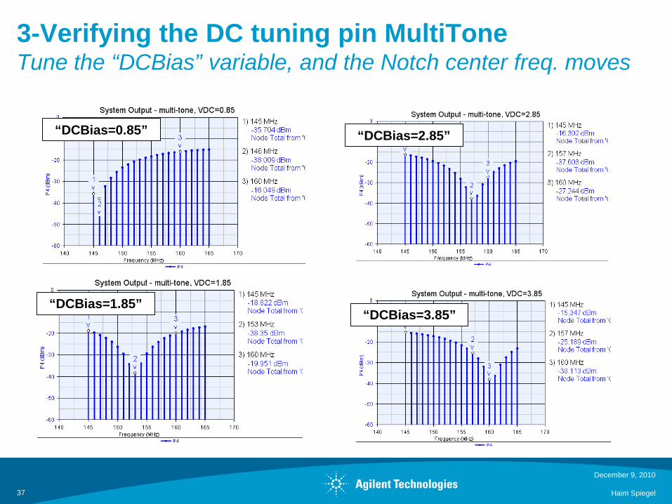
3-Verifying the DC tuning pin MultiToneTune the “DCBias” variable, and the Notch center freq. moves
December 9, 2010
Haim Spiegel37
“DCBias=0.85”
“DCBias=1.85”
“DCBias=2.85”
“DCBias=3.85”
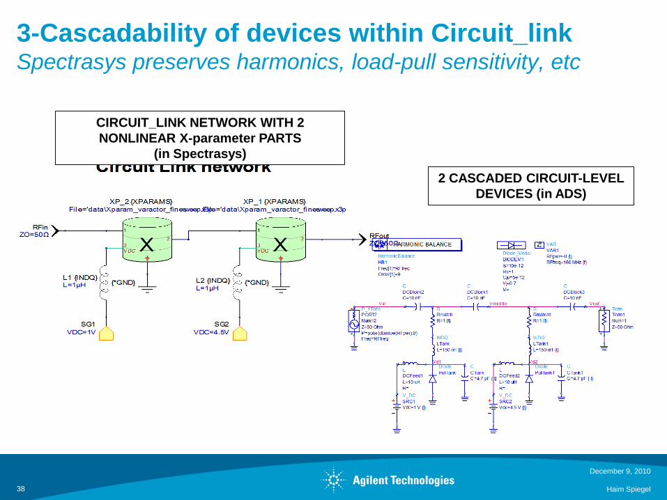
3-Cascadability of devices within Circuit_linkSpectrasys preserves harmonics, load-pull sensitivity, etc
December 9, 2010
Haim Spiegel38
CIRCUIT_LINK NETWORK WITH 2 NONLINEAR X-parameter PARTS
(in Spectrasys)
2 CASCADED CIRCUIT-LEVEL DEVICES (in ADS)
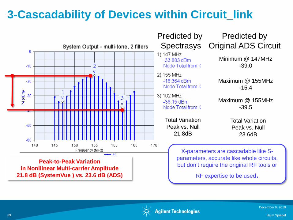
3-Cascadability of Devices within Circuit_link
December 9, 2010
Haim Spiegel39
Predicted by Original ADS Circuit
Minimum @ 147MHz-39.0
Maximum @ 155MHz-15.4
Maximum @ 155MHz-39.5
Total VariationPeak vs. Null
23.6dB
Total VariationPeak vs. Null
21.8dB
Predicted by Spectrasys
Peak-to-Peak Variation in Nonllinear Multi-carrier Amplitude
21.8 dB (SystemVue ) vs. 23.6 dB (ADS)
X-parameters are cascadable like S-parameters, accurate like whole circuits, but don’t require the original RF tools or
RF expertise to be used.
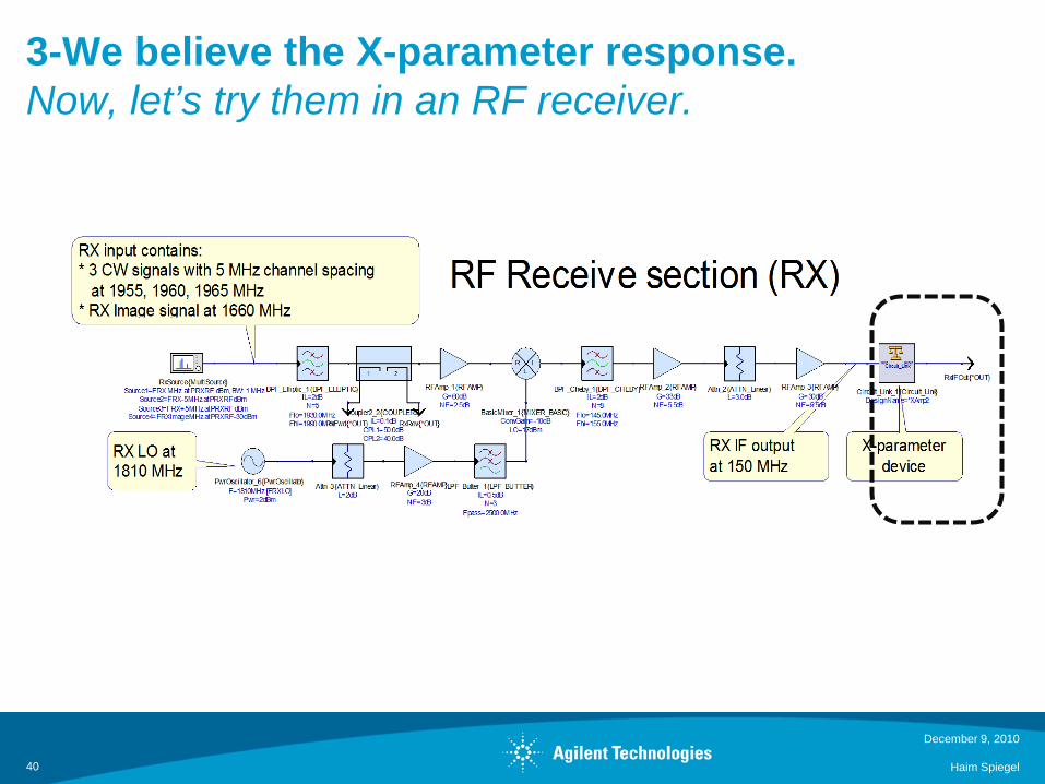
3-We believe the X-parameter response. Now, let’s try them in an RF receiver.
December 9, 2010
Haim Spiegel40
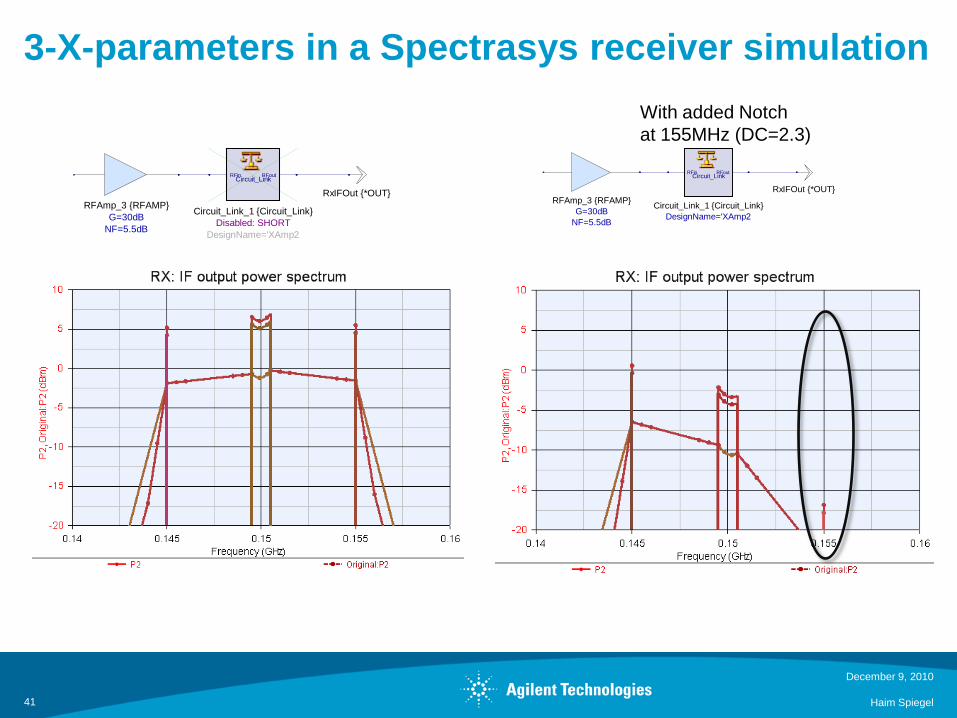
3-X-parameters in a Spectrasys receiver simulation
December 9, 2010
Haim Spiegel41
NF=5.5dBG=30dB
RFAmp_3 RFAMPRxIFOut *OUT
Circuit_LinkRFin RFout
DesignName='XAmp2Disabled: SHORT
Circuit_Link_1 Circuit_LinkNF=5.5dBG=30dB
RFAmp_3 RFAMPRxIFOut *OUT
Circuit_LinkRFin RFout
DesignName='XAmp2Circuit_Link_1 Circuit_Link
With added Notchat 155MHz (DC=2.3)
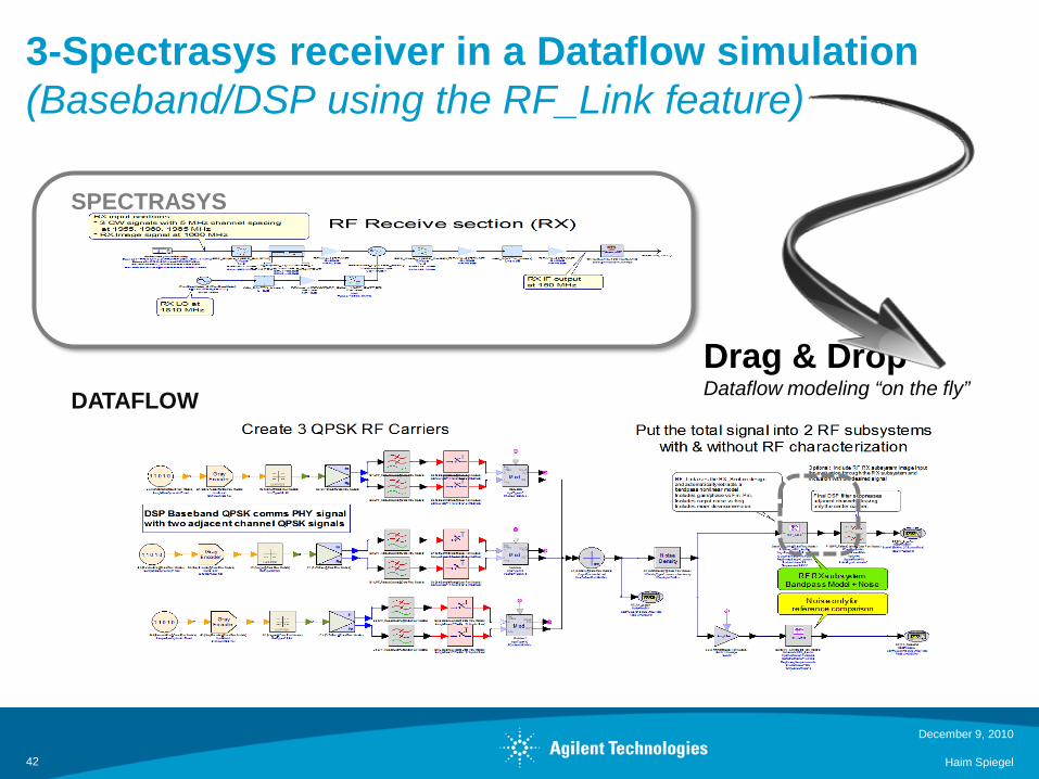
3-Spectrasys receiver in a Dataflow simulation(Baseband/DSP using the RF_Link feature)
December 9, 2010
Haim Spiegel42
Drag & DropDataflow modeling “on the fly”
SPECTRASYS
DATAFLOW
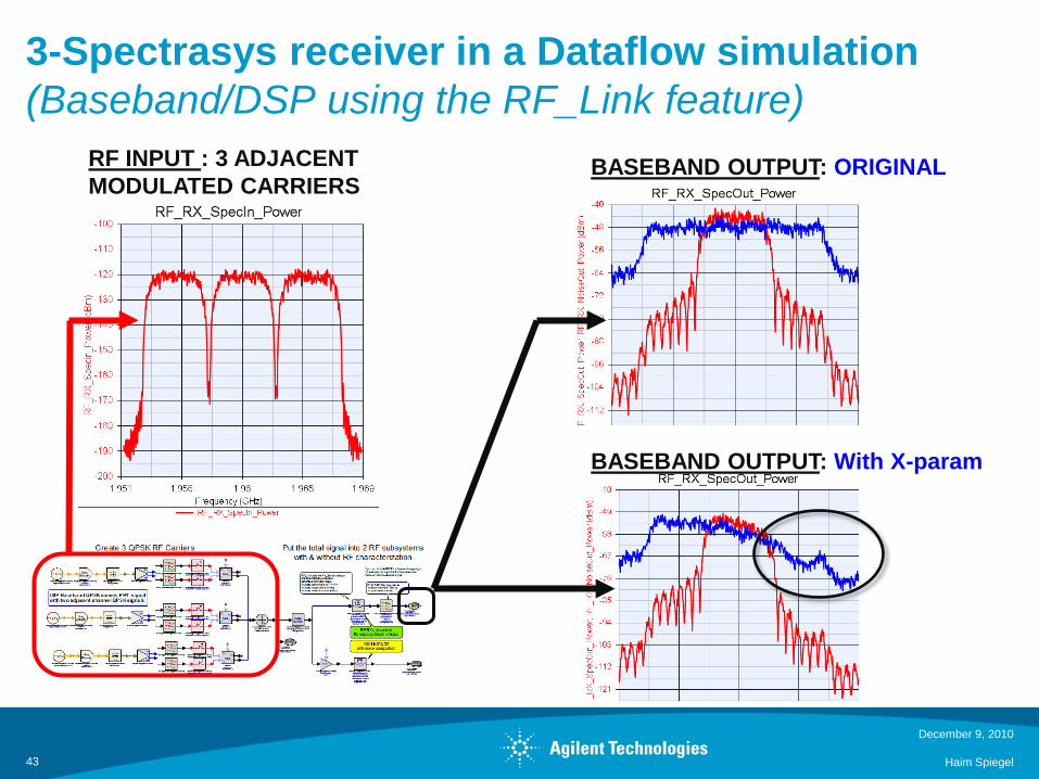
3-Spectrasys receiver in a Dataflow simulation(Baseband/DSP using the RF_Link feature)
December 9, 2010
Haim Spiegel43
RF INPUT : 3 ADJACENT MODULATED CARRIERS
BASEBAND OUTPUT: ORIGINAL
BASEBAND OUTPUT: With X-param
Outline
Problem Statement: The RF-Baseband Design Gap
What are X-parameters?
How can X-parameters fit into System-Level Tools?– Tools Used : Agilent EEsof ADS and SystemVue
Case study Based on Power Amplifier X Parameter model1. QPSK Modulation2. Radar Example3. Tunable Non-Linear Notch Filter
NEXT1. Digital Pre-Distortion
December 9, 2010
Haim Spiegel44
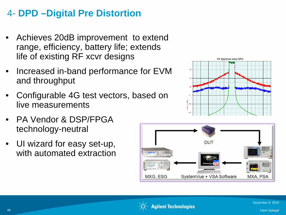
4- DPD –Digital Pre Distortion
December 9, 2010
Haim Spiegel45
• Achieves 20dB improvement to extend range, efficiency, battery life; extends life of existing RF xcvr designs
• Increased in-band performance for EVM and throughput
• Configurable 4G test vectors, based on live measurements
• PA Vendor & DSP/FPGA technology-neutral
• UI wizard for easy set-up, with automated extraction
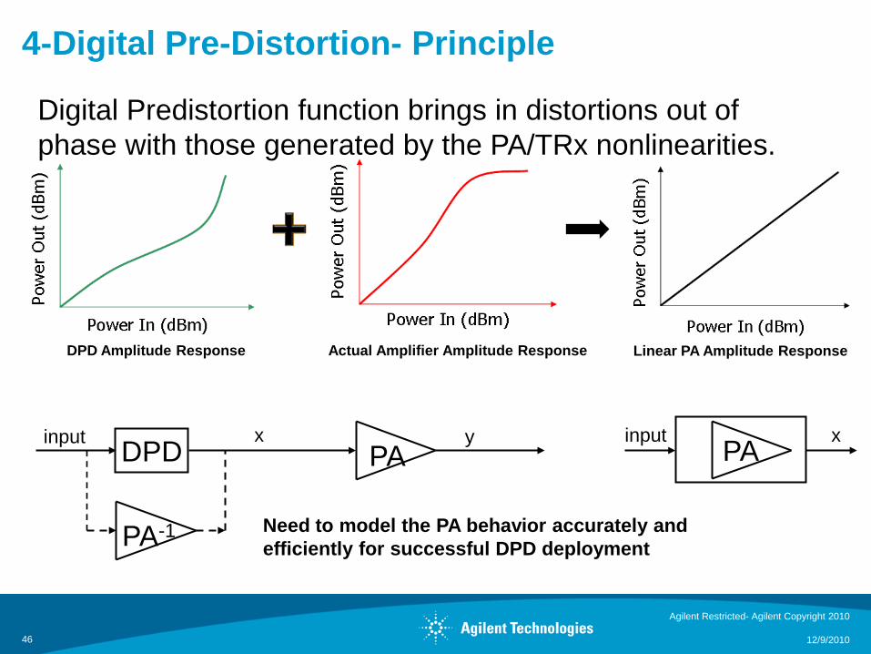
4-Digital Pre-Distortion- Principle
Agilent Restricted- Agilent Copyright 2010
12/9/201046
Actual Amplifier Amplitude ResponseDPD Amplitude Response Linear PA Amplitude Response
DPD PA PA
PA-1
input x y input x
Digital Predistortion function brings in distortions out of phase with those generated by the PA/TRx nonlinearities.
Need to model the PA behavior accurately andefficiently for successful DPD deployment
4-Digital Pre-Distortion- Principle
Agilent Restricted- Agilent Copyright 2010
12/9/201047
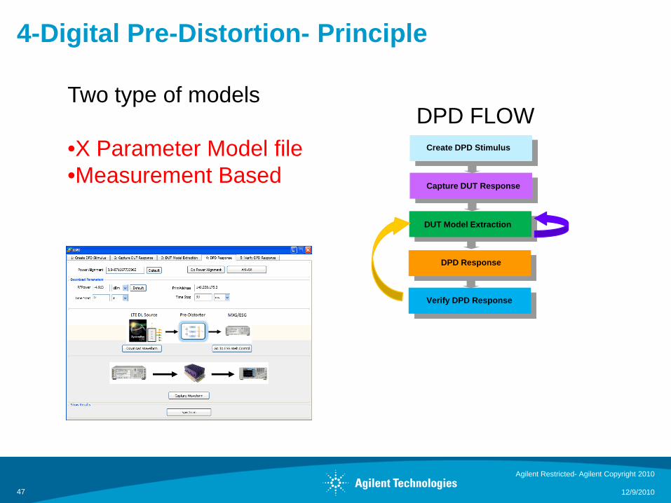
Create DPD Stimulus
Capture DUT Response
DUT Model Extraction
DPD Response
Verify DPD Response
Two type of models
•X Parameter Model file•Measurement Based
DPD FLOW
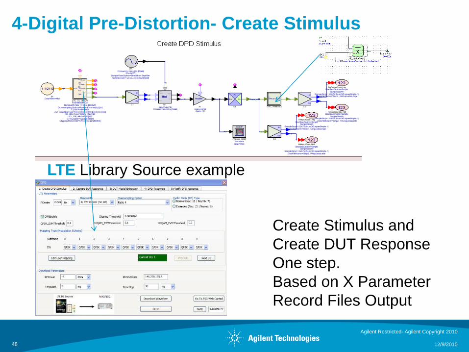
4-Digital Pre-Distortion- Create Stimulus
Agilent Restricted- Agilent Copyright 2010
12/9/201048
Create Stimulus andCreate DUT ResponseOne step.Based on X ParameterRecord Files Output
LTE Library Source example
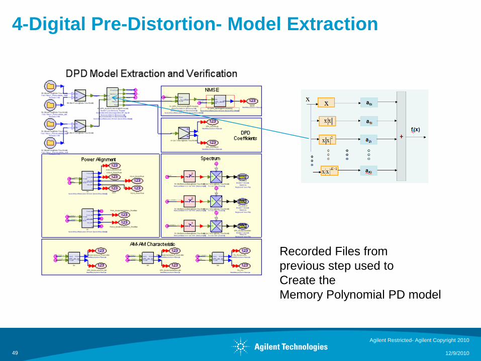
4-Digital Pre-Distortion- Model Extraction
Agilent Restricted- Agilent Copyright 2010
12/9/201049
Recorded Files from previous step used toCreate the Memory Polynomial PD model
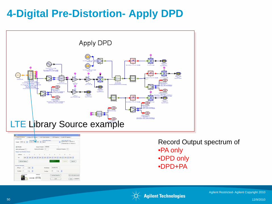
4-Digital Pre-Distortion- Apply DPD
Agilent Restricted- Agilent Copyright 2010
12/9/201050
Record Output spectrum of•PA only•DPD only•DPD+PA
LTE Library Source example
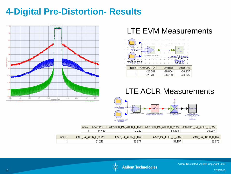
4-Digital Pre-Distortion- Results
Agilent Restricted- Agilent Copyright 2010
12/9/201051
LTE EVM Measurements
LTE ACLR Measurements
OutlineProblem Statement: The RF-Baseband Design Gap
What are X-parameters?
How can X-parameters fit into System-Level Tools?– Tools Used : Agilent EEsof ADS and SystemVue
Case study Based on Power Amplifier X Parameter model1. QPSK Modulation2. Radar Example3. Tunable Non-Linear Notch Filter4. Digital Pre-Distortion
NEXT
Conclusion
December 9, 2010
Haim Spiegel52
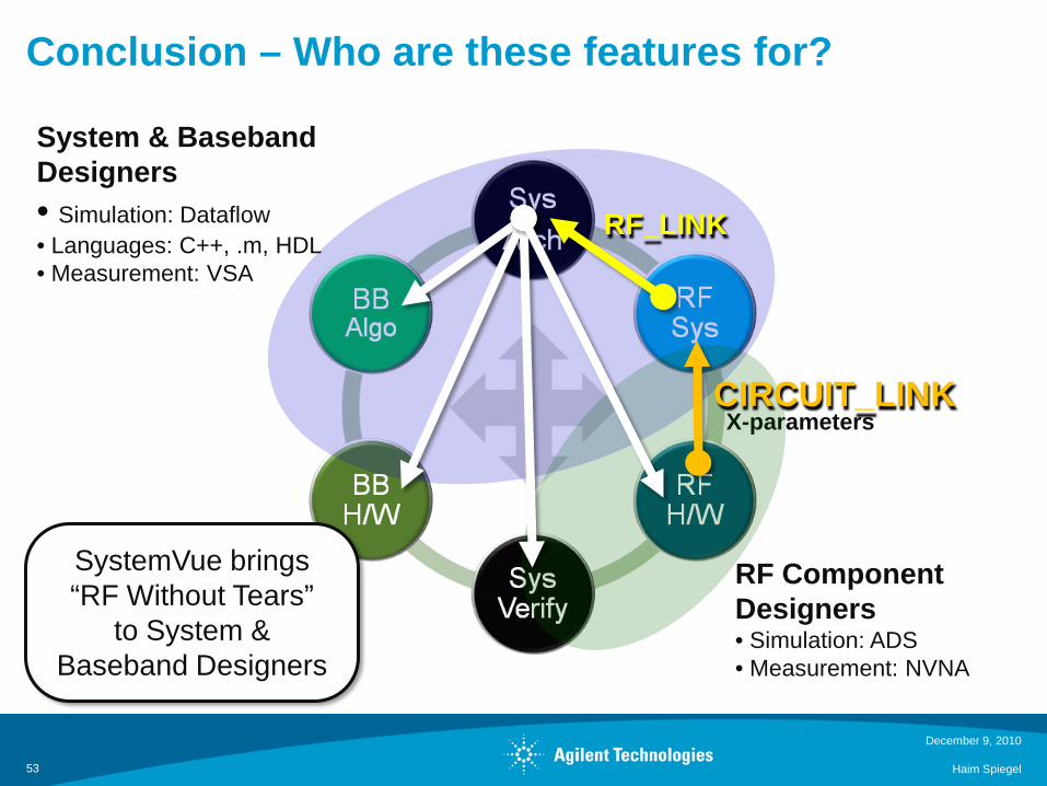
Conclusion – Who are these features for?
December 9, 2010
Haim Spiegel53
X-parameters
RF_LINK
CIRCUIT_LINK
RF Component Designers• Simulation: ADS• Measurement: NVNA
System & Baseband Designers• Simulation: Dataflow• Languages: C++, .m, HDL• Measurement: VSA
SystemVue brings“RF Without Tears”
to System & Baseband Designers

ConclusionSystemVue is a Comms ESL environment that “speaks RF”
Easy Generation of X Parameter from ADS tool
X-parameters and RF_Link provide implementation-based design flow closure to RF, System, and Baseband teams
Digital Pre Distortion Utility to easy DPD design
SystemVue maximizes speed, accuracy, and design flow simplicity for the non-RF audience, who today are including few (or no) RF effects in link-level and block-level dataflow simulations.
EEsof Israel: Avishai Viernik and Haim Spiegel
03-9288509 03-9288514
December 9, 2010
Haim Spiegel54