Agilent G4234A/B/C Valve Kit MCT Instructions Technologies Agilent G4234A/B/C Valve Kit MCT...
12
Agilent Technologies Agilent G4234A/B/C Valve Kit MCT Instructions Agilent G4234A/B/C Valve Kit MCT - Instructions Technical Information about Agilent Valve Kits G4234A/B/C for use with the Infinity II Series Multi Column Thermostat G7116B. Contents Typical Applications of the G4234A/B/C Valve Kit 2 Multi Column Selection 2 Method Development 3 Delivery Checklist 4 Specifications (G4234A/B/C) 5 Install the Valve Heads 6 Remove the Transportation Lock and the Valve Dummy 6 Install the Valve Head and Connect Capillaries 7 Install the Capillaries 10 Parts (G4234A/B/C Valve Kit) 12 Replacement Parts for the G4234A/B/C Valve Kit 12
Transcript of Agilent G4234A/B/C Valve Kit MCT Instructions Technologies Agilent G4234A/B/C Valve Kit MCT...
Agilent G4234A/B/C Valve Kit MCT
Instructions
Agilent G4234A/B/C Valve Kit MCT - InstructionsTechnical Information about Agilent Valve Kits G4234A/B/C for use with the Infinity II Series Multi Column Thermostat G7116B.
Contents
Typical Applications of the G4234A/B/C Valve Kit 2
Multi Column Selection 2Method Development 3
Delivery Checklist 4
Specifications (G4234A/B/C) 5
Install the Valve Heads 6
Remove the Transportation Lock and the Valve Dummy 6Install the Valve Head and Connect Capillaries 7
Install the Capillaries 10
Parts (G4234A/B/C Valve Kit) 12
Replacement Parts for the G4234A/B/C Valve Kit 12
Agilent Technologies

Typical Applications of the G4234A/B/C Valve Kit Multi Column Selection
Typical Applications of the G4234A/B/C Valve Kit
Multi Column Selection
2
Advantages:
• Increase productivity
• Higher instrument up- time
Quickly change between up to four different stationary phases for different applications, or use identical stationary phases in columns with different dimensions for either faster run- times (short columns) or higher resolution (long columns) or for loading studies with different internal diameters.
Figure 1 Multiple column selection (example of schematic setup for 6 column selector)
Typical Applications of the G4234A/B/C Valve KitMethod Development
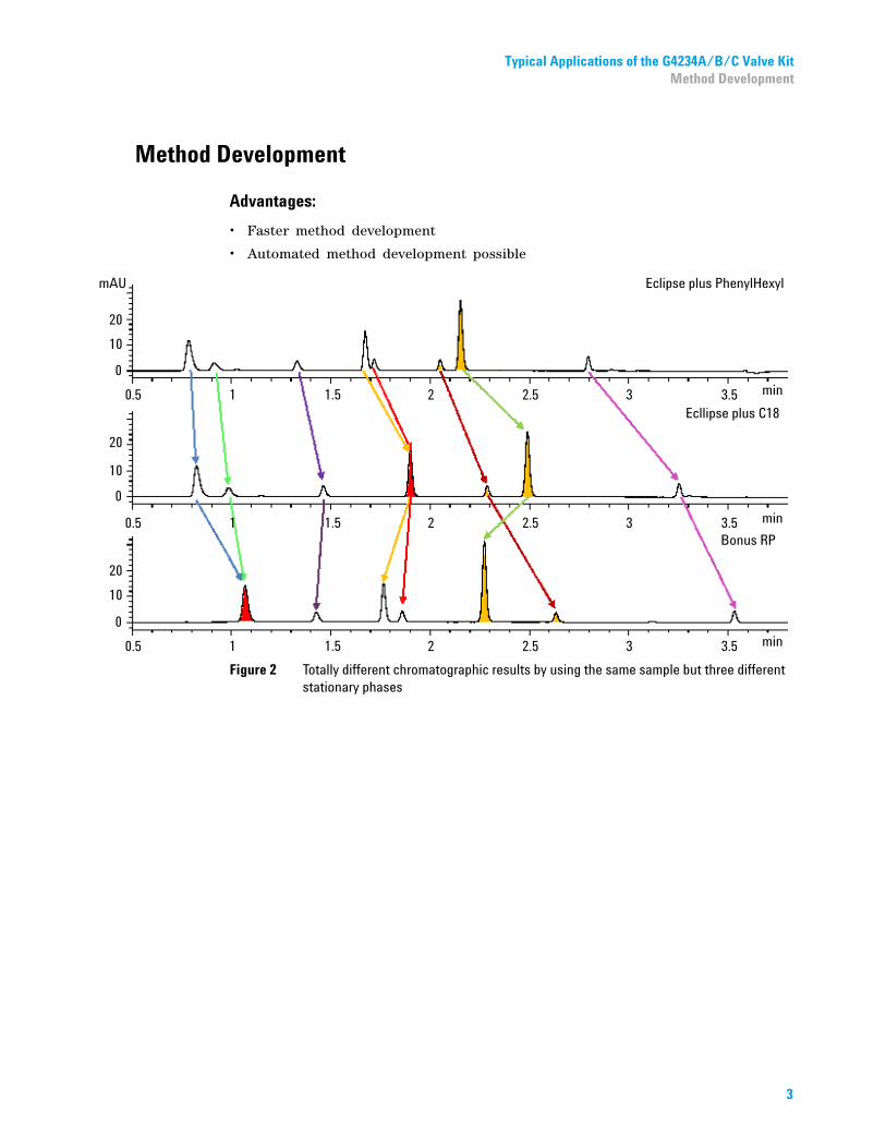
Method Development
Advantages:
• Faster method development
• Automated method development possible
Figure 2 Totally different chromatographic results by using the same sample but three different stationary phases
3

Delivery Checklist Method Development
Delivery Checklist
4
Delivery Checklist
Item p/n Description
1 5067-4146 Valve head 6 column selector (600 bar)G4234A
2 5067-4142 Valve head 6 column selector (1200 bar)G4234B
3 5067-4273 Valve head 6 column selector (1300 bar)G4234C
4 5067-4270 6-Column Selector Capillary Kit 0.12 mm ID, MCT (OPTIONAL)
6- Column Selector Capillary Kit 0.12 mm ID, MCT (5067- 4270), contains:
# p/n Description
6 G7116-60015 Heat Exchanger Assembly 1.6 µL-Z Quick Connect Heatexchanger Standard Flow
6 5500-1201 Capillary SST 0.12x105mm SL-- PS-LSQuick Connect Heatexchanger to column
6 G7167-68703 Fitting Intermediate Kitfitting for column, capillary 5500-1201
6 5500-1199 Capillary SST 0.12x130mm M4-SL PS-PS Valve to Quick Connect Heatexchanger
6 5500-1200 Capillary SST 0.12x130mm M4 PS-NS LSColumn to valve
1 5063-6591 PEEK Fittings 10/PKColumn outlet fitting for capillary 5500-1200
1 5500-1202 Capillary SST 0.12x500mm M4-SL PS-PS Autosampler to valve
1 5500-1203 Capillary SST 0.12x280mm M4-SL PS-PSValve to detector
1 5500-1204 Capillary SST 0.12x150mm M4-M4 PS-PSValve to valve (bypass)
1 G1375-87326 Waste tubeWaste tube incl. fitting
2 5067-6141 M4 Blank nutBlock unused ports
1 5023-2504 Hex driver SW-4 slittedTool for M4 fittings
6 G7116-68004 Column Holder Clamp (2/PK) for Infinity II
1 5043-0915 Fitting mounting toolfor bio-inert capillariesTool for PCHex
Specifications (G4234A/B/C)Method Development
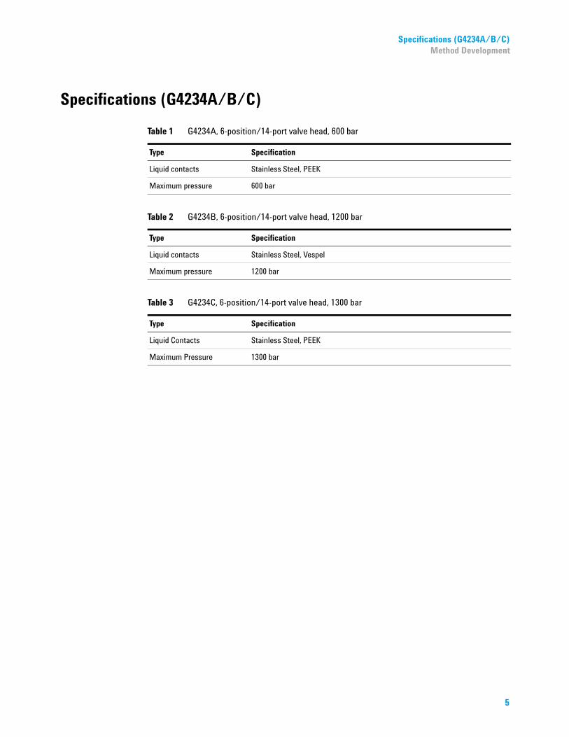
Specifications (G4234A/B/C)
Table 1 G4234A, 6-position/14-port valve head, 600 bar
Type Specification
Liquid contacts Stainless Steel, PEEK
Maximum pressure 600 bar
Table 2 G4234B, 6-position/14-port valve head, 1200 bar
Type Specification
Liquid contacts Stainless Steel, Vespel
Maximum pressure 1200 bar
Table 3 G4234C, 6-position/14-port valve head, 1300 bar
Type Specification
Liquid Contacts Stainless Steel, PEEK
Maximum Pressure 1300 bar
5

Install the Valve Heads Remove the Transportation Lock and the Valve Dummy
Install the Valve Heads
6
The valve drives are factory- installed in the 1290 Infinity II Multicolumn Thermostat. The valve heads are interchangeable and can be easily mounted.
At the first installation, the transportation lock and the dummy valve have to be removed, see “Remove the Transportation Lock and the Valve Dummy” on page 6. The valve heads can be installed by mounting the valve heads onto the valve drives and fastening the nut manually (do not use any tools).
Be sure that the guide pin snaps into the groove of the valve drive thread.
1 When unscrewing the transportation lock, push it back until the last screw is removed - the valve rail is spring-loaded.
2 Press on the valve dummy to release it (spring-loaded valve rail).
3 4
Remove the Transportation Lock and the Valve Dummy
NOTE The valves are mounted on pull-out rails to allow easy installation of capillaries. Push the valve gently into its housing until it snaps into the inner position, push it again and it slides out.
When all capillaries are installed, push the valve back into its housing, see “Install the Valve Head and Connect Capillaries” on page 7.

Install the Valve HeadsInstall the Valve Head and Connect Capillaries
Install the Valve Head and Connect Capillaries
The valve actuator contains sensitive optical parts, which need to be protected from dust and
other pollutions. Pollution of these parts can impair the accurate selection of valve ports and therefore bias measurement results.➔ Always install a valve head for operation and storage. For protecting the actuator, a dummyvalve head can be used instead of a functional valve. Do not touch parts inside the actuator.
CAUTION
Column Damage or Bias Measurement Results
Switching the valve to a wrong position can damage the column or bias measurement results.
➔ Fit the lobe to the groove to make sure the valve is switched to the correct position.
CAUTION
Valve Damage
Using a low pressure valve on the high pressure side can damage the valve.
➔ When using multiple column compartments as part of a method development solution, makesure that the high pressure valve head is connected to the autosampler and the low pressurevalve head is connected to the detector.
CAUTION
NOTE For a correct installation of the valve head, the outside pin (red) must completely fit into the outside groove on the valve drive’s shaft (red). A correct installation is only possible if the two pins (green and blue) on the valve head fit into their corresponding grooves on the valve drive’s actuator axis. Their match depends on the diameter of the pin and groove.
7

Install the Valve Heads Install the Valve Head and Connect Capillaries
1 Insert the valve head into the valve shaft.
ORIf the outside pin does not fit into the outside groove, you have to turn the valve head until you feel that the two pins snap into the grooves. Now you should feel additional resistance from the valve drive while continue turning the valve head until the pin fits into the groove.
2 When the outer pin is locked into the groove, manually screw the nut onto the valve head.
NOTEFasten the nut manually. Do not use any tools.
8
Install the Valve HeadsInstall the Valve Head and Connect Capillaries
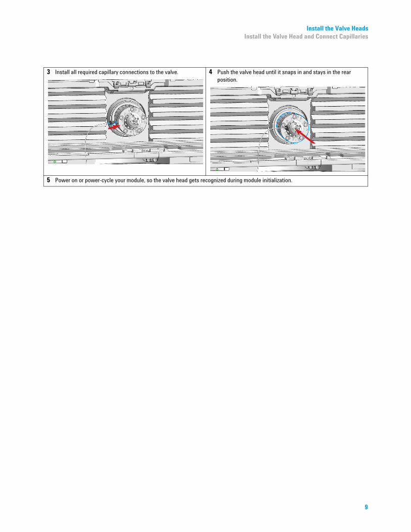
3 Install all required capillary connections to the valve. 4 Push the valve head until it snaps in and stays in the rear position.
5 Power on or power-cycle your module, so the valve head gets recognized during module initialization.
9
Install the Capillaries Install the Valve Head and Connect Capillaries
Install the Capillaries
Install the Capillaries (G4234A/B)
10
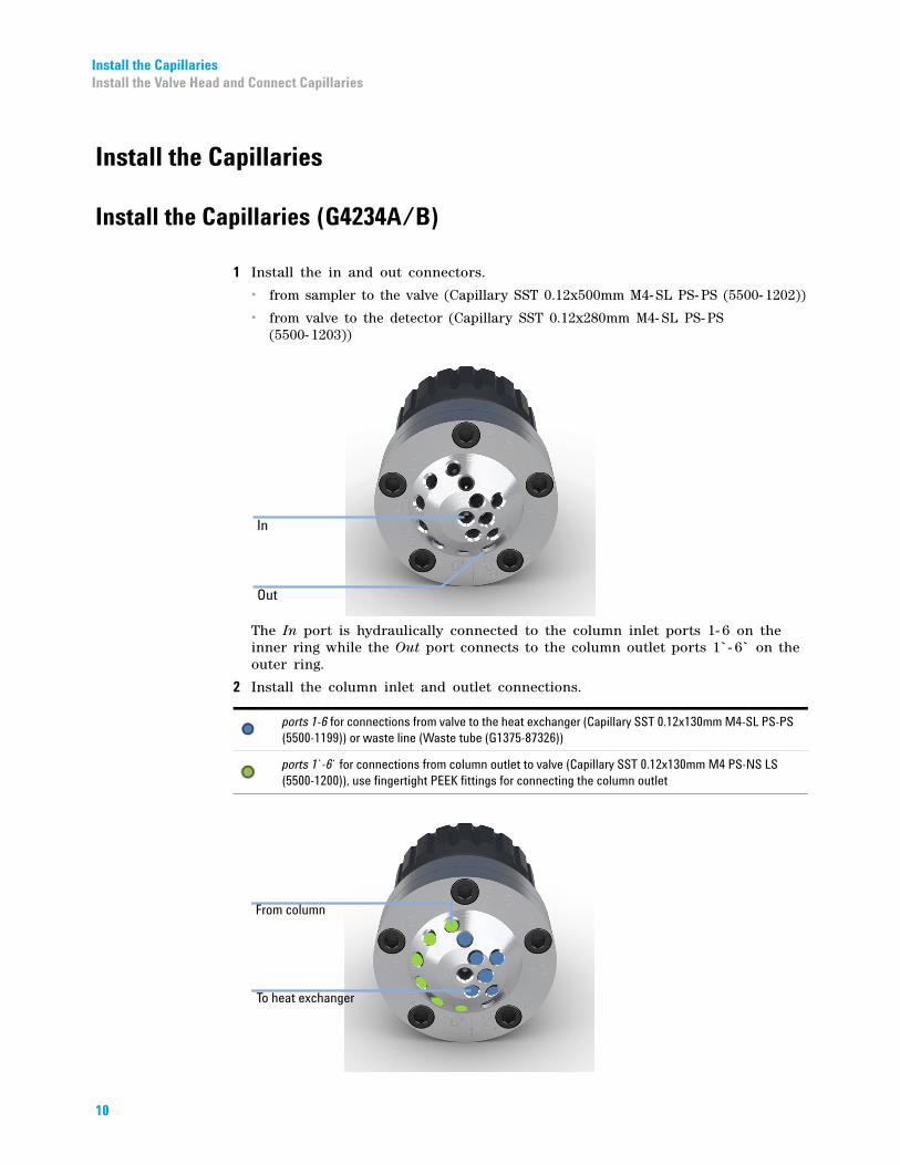
1 Install the in and out connectors.
• from sampler to the valve (Capillary SST 0.12x500mm M4- SL PS- PS (5500- 1202))
• from valve to the detector (Capillary SST 0.12x280mm M4- SL PS- PS(5500- 1203))
The In port is hydraulically connected to the column inlet ports 1- 6 on the inner ring while the Out port connects to the column outlet ports 1`- 6` on the outer ring.
2 Install the column inlet and outlet connections.
ports 1-6 for connections from valve to the heat exchanger (Capillary SST 0.12x130mm M4-SL PS-PS (5500-1199)) or waste line (Waste tube (G1375-87326))
ports 1`-6` for connections from column outlet to valve (Capillary SST 0.12x130mm M4 PS-NS LS (5500-1200)), use fingertight PEEK fittings for connecting the column outlet
Install the CapillariesInstall the Valve Head and Connect Capillaries
Install the Capillaries (G4234C)
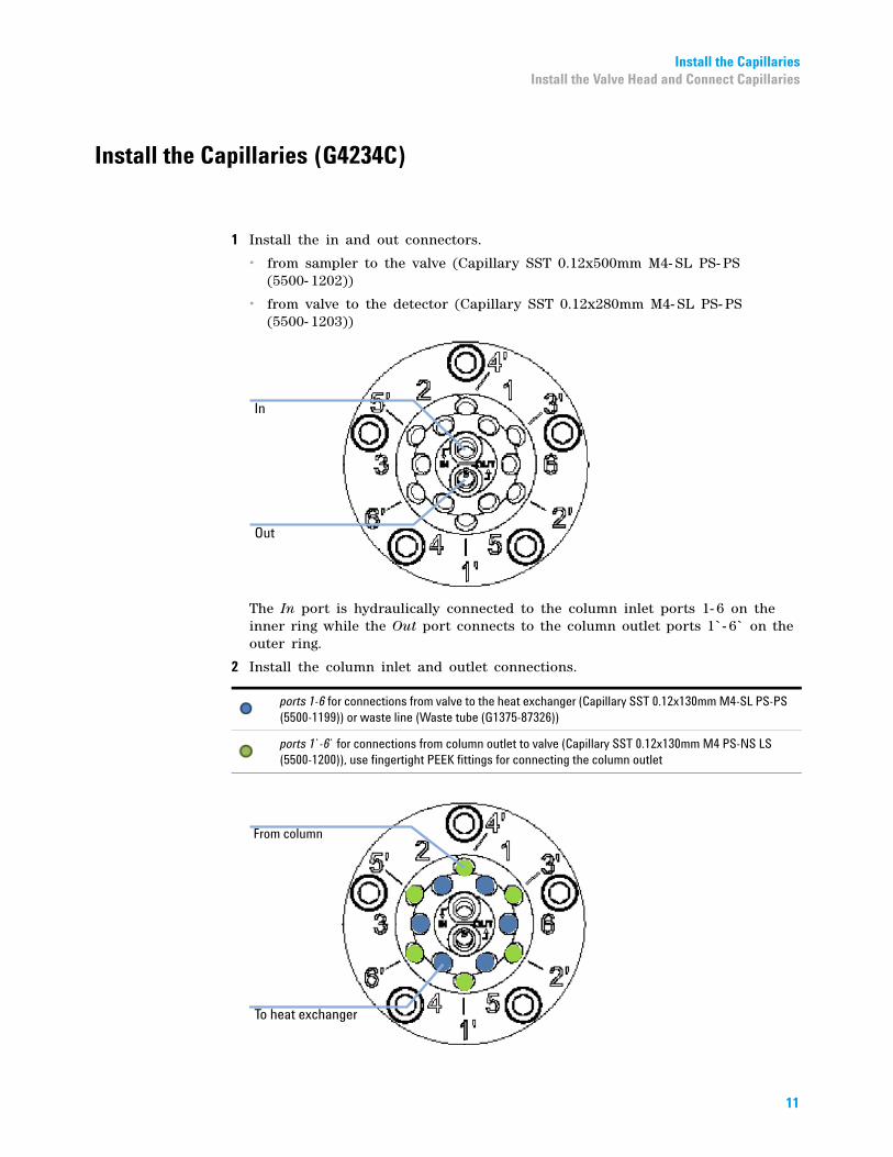
1 Install the in and out connectors.
• from sampler to the valve (Capillary SST 0.12x500mm M4- SL PS- PS(5500- 1202))
• from valve to the detector (Capillary SST 0.12x280mm M4- SL PS- PS(5500- 1203))
The In port is hydraulically connected to the column inlet ports 1- 6 on the inner ring while the Out port connects to the column outlet ports 1`- 6` on the outer ring.
2 Install the column inlet and outlet connections.
ports 1-6 for connections from valve to the heat exchanger (Capillary SST 0.12x130mm M4-SL PS-PS (5500-1199)) or waste line (Waste tube (G1375-87326))
ports 1`-6` for connections from column outlet to valve (Capillary SST 0.12x130mm M4 PS-NS LS (5500-1200)), use fingertight PEEK fittings for connecting the column outlet
11
Parts (G4234A/B/C Valve Kit) Replacement Parts for the G4234A/B/C Valve Kit
Parts (G4234A/B/C Valve Kit)
Replacement Parts for the G4234A/B/C Valve Kit
*G4234-90*G4234-90G4234-90003
nt parts
Table 4 ReplacemeValve Rotor Seal Stator Head Stator Screws (pack of 10) Bearing Ring
5067-41466 Column Selector, 600 bar
5068-0076(PEEK)
5068-0077 5068-0089 1535-4045
5067-41426 Column Selector, 1200 bar
5068-0067(Vespel)
5068-0077 5068-0089 1535-4045
5067-42736 Column Selector, 1300 bar
5068-0212(PEEK)
5068-0211 5068-0089 1535-4045
003*003*
Part Number: G4234- 90003 Rev. B
Edition: 02/2016Printed in Germany
© Agilent Technologies, Inc 2015, 2016
Agilent Technologies, IncHewlett-Packard-Strasse 8
76337 WaldbronnGermany
glicht
Sticky Note
Marked set by glicht
glicht
Sticky Note
Marked set by glicht