Agilent Drivers for Thermo Scientific Chromeleon 7 · Agilent Drivers for Thermo Scientific...
96
Agilent Technologies Agilent Drivers for Thermo Scientific Chromeleon 7 User's Guide Agilent Drivers User's Guide
Transcript of Agilent Drivers for Thermo Scientific Chromeleon 7 · Agilent Drivers for Thermo Scientific...

Agilent Drivers for Thermo Scientific Chromeleon 7
User's GuideAgilent Drivers User's Guide
Agilent Technologies

Notices© Agilent Technologies, Inc. 2017No part of this manual may be reproduced in any form or by any means (including electronic storage and retrieval or transla-tion into a foreign language) without prior agreement and written consent from Agi-lent Technologies, Inc. as governed by United States and international copyright laws.
Manual Part NumberG4098-90000
Edition04/17Printed in GermanyAgilent TechnologiesHewlett-Packard-Strasse 8 76337 Waldbronn
WarrantyThe material contained in this docu-ment is provided “as is,” and is sub-ject to being changed, without notice, in future editions. Further, to the max-imum extent permitted by applicable law, Agilent disclaims all warranties, either express or implied, with regard to this manual and any information contained herein, including but not limited to the implied warranties of merchantability and fitness for a par-ticular purpose. Agilent shall not be liable for errors or for incidental or consequential damages in connection with the furnishing, use, or perfor-mance of this document or of any information contained herein. Should Agilent and the user have a separate written agreement with warranty terms covering the material in this document that conflict with these terms, the warranty terms in the sep-arate agreement shall control.
Technology Licenses The hardware and/or software described in this document are furnished under a license and may be used or copied only in accordance with the terms of such license.
Restricted Rights LegendIf software is for use in the performance of a U.S. Government prime contract or sub-contract, Software is delivered and licensed as “Commercial computer software” as defined in DFAR 252.227-7014 (June 1995), or as a “commercial item” as defined in FAR 2.101(a) or as “Restricted computer software” as defined in FAR 52.227-19 (June 1987) or any equivalent agency regu-lation or contract clause. Use, duplication or disclosure of Software is subject to Agi-lent Technologies’ standard commercial license terms, and non-DOD Departments and Agencies of the U.S. Government will
receive no greater than Restricted Rights as defined in FAR 52.227-19(c)(1-2) (June 1987). U.S. Government users will receive no greater than Limited Rights as defined in FAR 52.227-14 (June 1987) or DFAR 252.227-7015 (b)(2) (November 1995), as applicable in any technical data.
Safety Notices
CAUTION
A CAUTION notice denotes a hazard. It calls attention to an operating procedure, practice, or the like that, if not correctly per-formed or adhered to, could result in damage to the product or loss of important data. Do not proceed beyond a CAUTION notice until the indicated condi-tions are fully understood and met.
WARNING
A WARNING notice denotes a hazard. It calls attention to an operating procedure, practice, or the like that, if not correctly performed or adhered to, could result in personal injury or death. Do not proceed beyond a WARNING notice until the indi-cated conditions are fully understood and met.
Software RevisionThis guide is valid for the Agilent Drivers for Chromeleon 7 Version 1.1 executed in the environment of Thermo Scientific Chromeleon 7 Data System (CDS) Version 7.2 SR 5.
Thermo Scientific and Chromeleon are registered trademarks of Thermo Fisher.
Agilent Drivers User's Guide
Contents
Contents
1 Introduction and Scope 5Terms and Abbreviations 6Introduction 7Overview of Features 8
2 Compatibility and System Requirements 9Chromeleon CDS/Agilent Driver Compatibility 10Software Components Required 11Chromeleon Licenses 12Supported Operating Systems 13Supported Hardware 14Software Updates 16
3 Installation 17Hardware Installation 18Software Installation 19Installation of the Agilent Drivers 20Software Verification 26Unattended Installation of the Agilent Drivers and Agilent Software Verification Tool 29Unattended Execution of the Software Verification Tool 30Agilent Drivers Co-Existence /Co-Execution with other drivers 31
4 Configuring the Agilent Drivers in the Chromeleon Instrument Configuration 33Configure your Agilent LC 34Create a Configuration Report 41Device and Signal Names 42Name appearance in the Chromeleon Console 44
5 Getting Started 45Direct Control of the Instrument 46
Agilent Drivers User's Guide 3
Contents
Setting Up an Instrument Method 53Running Injections 63LC System 64
6 Troubleshooting 67
7 Known Limitations 79
8 Appendix A 85
4 Agilent Drivers User's Guide
Agilent Drivers User's Guide
1Introduction and ScopeTerms and Abbreviations 6Introduction 7Overview of Features 8
This chapter provides introductory material for the User's Guide.
5Agilent Technologies

1 Introduction and ScopeTerms and Abbreviations
Terms and Abbreviations
Table 1 Terms and abbreviations used in this document
Term Description
Agilent Drivers Agilent Drivers for Chromeleon 7
Agilent Drivers for Thermo Scientific Chromeleon 7
Chromeleon Thermo Scientific Chromeleon 7 Chromatography Data System (CDS)
NOTEThermo Scientific and Chromeleon are registered trademarks of Thermo Fisher.
Thermo Fisher Thermo Fisher Scientific
DDK Driver Development Kit (from Thermo Fisher Scientific)
ICF Agilent Instrument Control Framework
6 Agilent Drivers User's Guide

Introduction and Scope 1Introduction
Introduction
Agilent Technologies first released the Instrument Control Framework (ICF) in March 2010 as a shell for the Agilent Instrument Driver Packages. Since then, ICF packages are built into the Chromeleon CDS by Thermo Fisher Scientific. Using ICF, certain Chromeleon-specific features are not supported; for example, the method script and direct instrument control using ePanels are not available.
The new integration of the Agilent Drivers for Chromeleon 7 includes the support for these Chromeleon-specific driver features.
This document describes
• how to install the Agilent Drivers
• how to configure the instrument
• how to run injections
• the method handling (Agilent Method user interface/Chromeleon Script Editor)
• how to migrate methods based on native drivers and ICF based drivers
• how to troubleshoot
NOTE When Agilent Drivers are controlling Agilent instruments, the communication between the computer and the instrument is coordinated by the Agilent Drivers and the Chromeleon software integration. Chromeleon, as the acting Data System, hosts the integration; the Agilent Drivers for Chromeleon 7 are a subcomponent.
Both companies are working closely together. For questions regarding the LC hardware, contact your local Agilent representative; for all other questions, contact Thermo Fisher.
Agilent Drivers User's Guide 7

1 Introduction and ScopeOverview of Features
Overview of Features
Table 2 Overview of features
Feature Chromeleon Native Driver
ICF Integration in Chromeleon
Agilent Drivers for Chromeleon 7
ePanels (Direct Control) Yes No 1.1
Command Tree/Script Method Parameters
Yes No 1.1
Command Tree/Script Control Parameters
Yes No 1.1 (direct control parameters)
Shutdown instrument Yes No 1.2
Built-In Diagnostics Yes No No
Method Version comparison Yes No 1.1
Audit Trail with parameters outside and inside a run
Yes Since A.02.01 ICF 1.1
Guided Method Wizard Yes No 1.1
Sampler Graphic Interface Yes No No
Method Printing Yes Yesmarked as ICF method
1.1 Printed as scripted method
Error Levels Yes No No
Simulation of an online module Yes No No
8 Agilent Drivers User's Guide
Agilent Drivers User's Guide
2Compatibility and System RequirementsChromeleon CDS/Agilent Driver Compatibility 10Software Components Required 11Chromeleon Licenses 12Supported Operating Systems 13Supported Hardware 14Software Updates 16
This chapter contains important information about compatibility and the hardware and software requirements.
9Agilent Technologies

2 Compatibility and System RequirementsChromeleon CDS/Agilent Driver Compatibility
Chromeleon CDS/Agilent Driver Compatibility
To ensure the alignment of compatible components, Thermo Fisher provides the tested and certified Agilent Drivers for Chromeleon 7 on the Chromeleon disk in the following location:
X:\Chromeleon 7.2.5\Packages\Agilent Chromeleon Driver
where X is the drive letter of the DVD drive.
10 Agilent Drivers User's Guide

Compatibility and System Requirements 2Software Components Required
Software Components Required
To operate Chromeleon 7 with the Agilent Driver for Chromeleon 7, the supported Chromeleon 7 /Agilent Drivers versions are:
The Agilent Drivers for Chromeleon 7 comprises two major components:
• Agilent_Drivers_for_Thermo_Chromeleon.msi
The Agilent Drivers for Chromeleon 7 installer is a single executable .msi file, that includes
• Agilent Driver for Thermo Chromeleon 7 (new integration adapter)
• Agilent Instrument Control Framework (ICF)
• Agilent Instrument Control Framework - LC Driver
• SVTTool.msi
• Agilent Software Verification Tool (SVT)
This separate .msi file installs the Agilent Software Verification Tool (SVT) to run the installation verification.
The main components for the Agilent Drivers and the SVT are visible in the Windows sections Program and Features (previously Add/Remove Programs).
NOTE Refer to “Installation” on page 17 for detailed information on the installation of the Agilent Drivers in combination with Chromeleon.
Table 3 Required Components
Chromeleon Revision Agilent Driver for Thermo Chromeleon 7
Including Agilent Instrument Control for
7.2 SR5 1.1 Agilent LC Instrumentation(see “Appendix A” on page 85)
Agilent Drivers User's Guide 11

2 Compatibility and System RequirementsChromeleon Licenses
Chromeleon Licenses
The Chromeleon licenses that are required to control Agilent instrumentation are shown in the following table:
Table 4 Chromeleon Licenses
License Required Optional
Control Agilent LC Instrument Class 3 3D Data Acquisition(to allow acquisition of 3D data from Diode-Array and Fluorescence Detectors)
12 Agilent Drivers User's Guide

Compatibility and System Requirements 2Supported Operating Systems
Supported Operating Systems
The operating systems supported are dependent on the requirements of the Chromeleon software (including Service Releases) and the Agilent Drivers (including Driver Updates). The Agilent Drivers for Chromeleon 7 version 1.1 has been validated to work with Chromeleon running on the following operating systems:
• Microsoft Windows 7 and 7 SP1, 32 Bit and 64 Bit
• Microsoft Windows 8.1, 64 Bit
• Microsoft Windows 10, 64 Bit
• Microsoft Windows 2012 Server R2, 64 Bit
For further details on the operating system and other system components (for example, Internet Explorer, Antivirus software, etc.) refer to the Chromeleon documentation and the release notes for Agilent Drivers for Chromeleon 7.
Agilent Drivers User's Guide 13
2 Compatibility and System RequirementsSupported Hardware
Supported Hardware
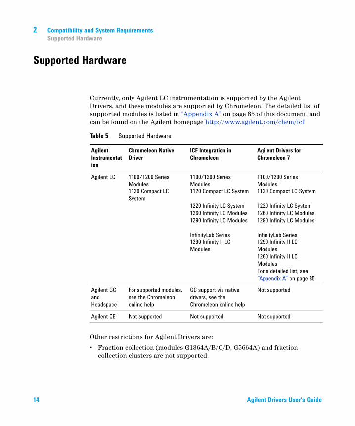
Currently, only Agilent LC instrumentation is supported by the Agilent Drivers, and these modules are supported by Chromeleon. The detailed list of supported modules is listed in “Appendix A” on page 85 of this document, and can be found on the Agilent homepage http://www.agilent.com/chem/icf
Other restrictions for Agilent Drivers are:
• Fraction collection (modules G1364A/B/C/D, G5664A) and fraction collection clusters are not supported.
Table 5 Supported Hardware
Agilent Instrumentation
Chromeleon Native Driver
ICF Integration in Chromeleon
Agilent Drivers for Chromeleon 7
Agilent LC 1100/1200 Series Modules1120 Compact LC System
1100/1200 Series Modules 1120 Compact LC System
1220 Infinity LC System1260 Infinity LC Modules1290 Infinity LC Modules
InfinityLab Series1290 Infinity II LC Modules
1100/1200 Series Modules 1120 Compact LC System
1220 Infinity LC System1260 Infinity LC Modules1290 Infinity LC Modules
InfinityLab Series1290 Infinity II LC Modules1260 Infinity II LC ModulesFor a detailed list, see “Appendix A” on page 85
Agilent GC and Headspace
For supported modules, see the Chromeleon online help
GC support via native drivers, see the Chromeleon online help
Not supported
Agilent CE Not supported Not supported Not supported
14 Agilent Drivers User's Guide
Compatibility and System Requirements 2Supported Hardware
• The firmware versions listed in the tables in “Appendix A” on page 85 are minimum requirements. In general, Thermo Fisher Scientific and Agilent Technologies recommend that you use the latest version of firmware.
If your system does not comply with the list of modules and minimum firmware requirements given on the Agilent web page, you cannot use Chromeleon with Agilent Drivers. In this case, Thermo Fisher Scientific and Agilent Technologies recommend that you update the firmware accordingly.
• Agilent releases LC firmware updates as so-called "firmware sets". The module firmware contained in each set is fully compatible and interoperable with all other module firmware of the same set. Do not mix firmware revisions between different sets. Agilent does not guarantee the correct operation of modules with mixed firmware revisions from older and newer firmware sets.
• Only LAN-based and RS232 USB-communicating modules are supported.
Modules connected using GPIB are not supported.
• The configuration of two samplers in one instrument stack is not supported.
• Manual injection is not supported (also listed in limitations).
Agilent Drivers User's Guide 15
2 Compatibility and System RequirementsSoftware Updates
Software Updates
Best practice is always to use the recommended and validated versions of Agilent Drivers and Thermo Scientific Chromeleon. However, it is sometimes necessary to update one software component independently of the other, in which case there may be limitations in use.
Updating the Agilent DriversThe Agilent Drivers can be updated without updating Chromeleon, for example, to fix Agilent Driver issues. Limitations: additional instruments and/or features included in the new version of the Agilent Drivers are not necessarily supported or functioning without errors.
Updating ChromeleonChromeleon can be updated without updating the Agilent Drivers, for example to fix Chromeleon issues. Limitations: new features designed to work with later versions of the Agilent Drivers will not work.
16 Agilent Drivers User's Guide

Agilent Drivers User's Guide
3InstallationHardware Installation 18Software Installation 19Installation of the Agilent Drivers 20
Automatic Installation using the Chromeleon Installer 20Manual Installation 21
Software Verification 26Unattended Installation of the Agilent Drivers and Agilent Software Verification Tool 29Unattended Execution of the Software Verification Tool 30Agilent Drivers Co-Existence /Co-Execution with other drivers 31
This chapter describes the steps required to install the Agilent Drivers with Chromeleon.
NOTE Ensure that the installation operator has full local Windows administrator privileges.
17Agilent Technologies
3 InstallationHardware Installation
Hardware Installation
Before you install the software, ensure that the hardware is correctly installed. Refer to the corresponding Agilent instrument/module manual for full details. The individual Agilent modules are connected with CAN cables; communication between the Agilent instrument and the PC uses a LAN connection. Install the LAN card in the detector module with the highest data load (hierarchy: DAD>FLD>MWD>VWD>RID).
18 Agilent Drivers User's Guide
Installation 3Software Installation
Software Installation
If an Agilent instrument is controlled from a remote client (for example, for editing methods or viewing instrument status), or when the Chromeleon instrument controller configuration containing the Agilent Drivers is changed from a remote client, install the Agilent Drivers package also on the remote client PC. Install the same version of the Agilent Drivers on all PCs.
Agilent Drivers User's Guide 19
3 InstallationInstallation of the Agilent Drivers
Installation of the Agilent Drivers
Automatic Installation using the Chromeleon InstallerThe Chromeleon Installer manages the installation of all required components, including the SVT.
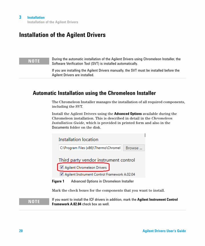
Install the Agilent Drivers using the Advanced Options available during the Chromeleon installation. This is described in detail in the Chromeleon Installation Guide, which is provided in printed form and also in the Documents folder on the disk.
Figure 1 Advanced Options in Chromeleon Installer
Mark the check boxes for the components that you want to install.
NOTE During the automatic installation of the Agilent Drivers using Chromeleon Installer, the Software Verification Tool (SVT) is installed automatically.
If you are installing the Agilent Drivers manually, the SVT must be installed before the Agilent Drivers are installed.
NOTE If you want to install the ICF drivers in addition, mark the Agilent Instrument Control Framework A.02.04 check box as well.
20 Agilent Drivers User's Guide
Installation 3Installation of the Agilent Drivers
The Software Verification tool (Agilent Software Verification Tool (SVT)). is automatically installed along with the Agilent Drivers, and remains on the PC for further updates.
Manual InstallationThe files required for manual installation are located on the Chromeleon DVD in the folder X:\Chromeleon 7.2.5\Packages\Agilent Chromeleon Driver (where as X is the driver letter of the DVD drive).
Before you install the Agilent Drivers, you must install the Software Verification tool, which is required for the installation of the Agilent Drivers.
Manual Installation of the Software Verification Tool1 Double-click the file SVTtool.msi to start the installation of the Software
Verification Tool.
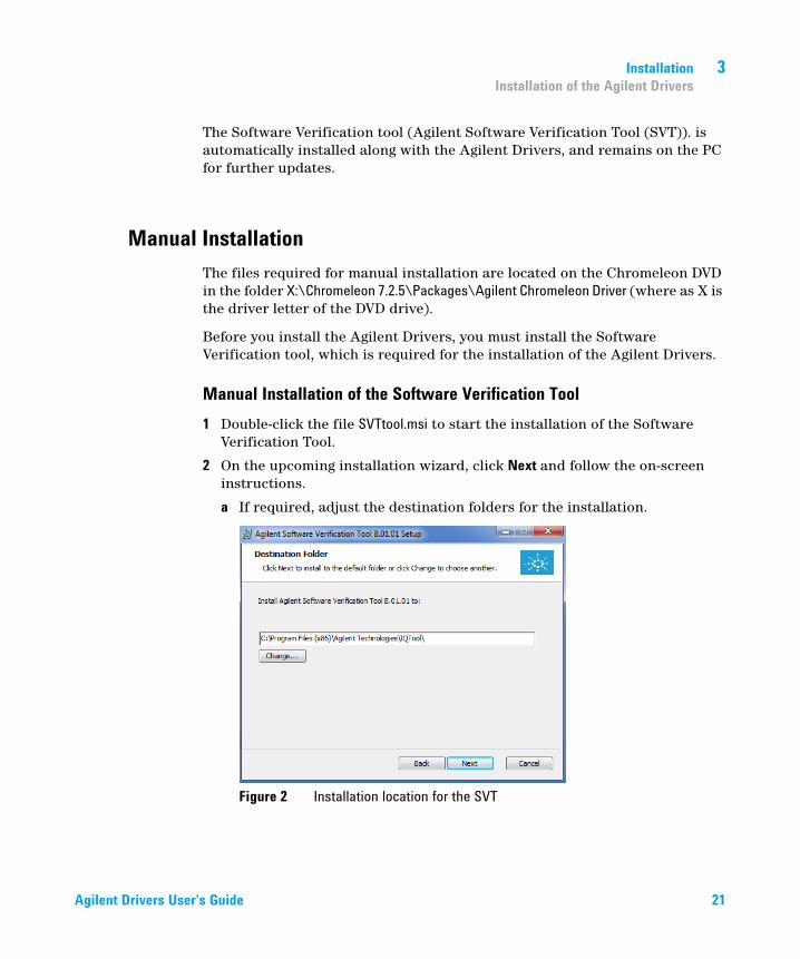
2 On the upcoming installation wizard, click Next and follow the on-screen instructions.
a If required, adjust the destination folders for the installation.
Figure 2 Installation location for the SVT
Agilent Drivers User's Guide 21
3 InstallationInstallation of the Agilent Drivers
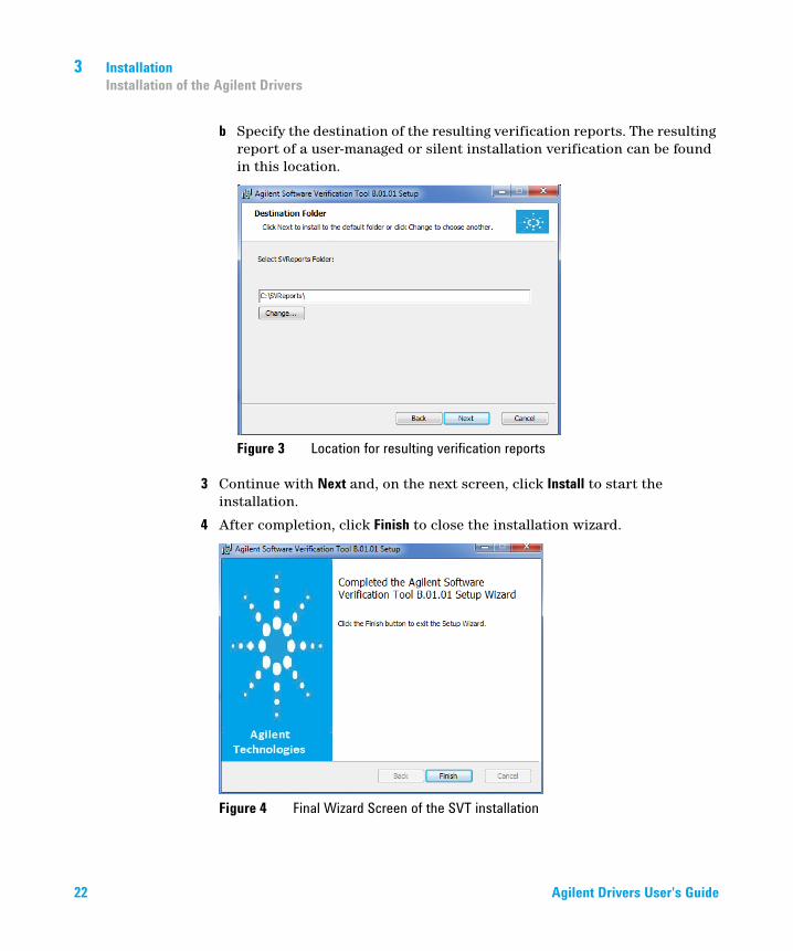
b Specify the destination of the resulting verification reports. The resulting report of a user-managed or silent installation verification can be found in this location.
Figure 3 Location for resulting verification reports
3 Continue with Next and, on the next screen, click Install to start the installation.
4 After completion, click Finish to close the installation wizard.
Figure 4 Final Wizard Screen of the SVT installation
22 Agilent Drivers User's Guide

Installation 3Installation of the Agilent Drivers
The Software Verification tool is now available in the Windows Start menu: Start > Agilent Technologies > Software Verification Tool.
Figure 5 The SVT in the Windows Start Menu
Manual Installation of the Agilent Drivers1 Double-click the file Agilent_Drivers_for_Thermo_Chromeleon.msi to start the
installation of the Agilent Drivers for Thermo Chromeleon 7.
2 On the upcoming setup screen, accept the license terms and continue with Install.
Agilent Drivers User's Guide 23

3 InstallationInstallation of the Agilent Drivers
3 Click Yes on the user account control to allow the installation of the Agilent Drivers.
4 To finalize the installation, click Finish.
Figure 6 Accept license terms
Figure 7 Finalize installation
24 Agilent Drivers User's Guide

Installation 3Installation of the Agilent Drivers
The final locations for the files are:
• 64-bit Windows C:\Program Files (x86)\Agilent Technologies\Agilent Drivers for Thermo Chromeleon
• 32-bit Windows C:\Program Files\Agilent Technologies\Agilent Drivers for Thermo Chromeleon
Agilent Drivers User's Guide 25

3 InstallationSoftware Verification
Software Verification
Agilent offers a Software Verification tool (SVT) to verify the correct installation of the software components.
• When the Chromeleon installation routine is used, the tool is installed along with the Agilent Drivers.
• When the Agilent Drivers are installed manually, the Software Verification tool needs to be installed manually, as it is not part of the Agilent Drivers.
Figure 8 Software Verification Tool (SVT)
In order to check the successful installation of the Agilent Drivers and its subcomponents, execute SVT. The default file location for the SVT tool is C:\Program Files (x86)\Agilent Technologies\IQTool.
1 Open Start > Programs > Agilent Technologies and select Software Verification Tool.
26 Agilent Drivers User's Guide
Installation 3Software Verification
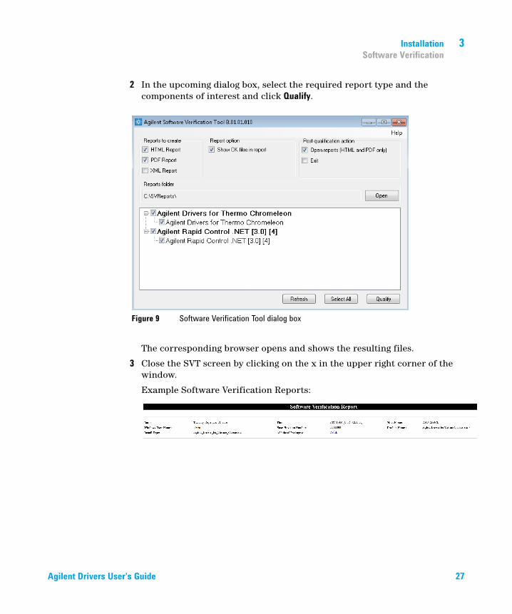
2 In the upcoming dialog box, select the required report type and the components of interest and click Qualify.
The corresponding browser opens and shows the resulting files.
3 Close the SVT screen by clicking on the x in the upper right corner of the window.
Example Software Verification Reports:
Figure 9 Software Verification Tool dialog box
Agilent Drivers User's Guide 27
3 InstallationSoftware Verification
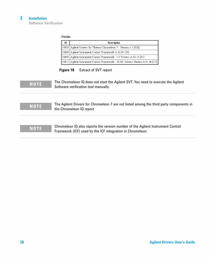
Figure 10 Extract of SVT report
NOTE The Chromeleon IQ does not start the Agilent SVT. You need to execute the Agilent Software verification tool manually.
NOTE The Agilent Drivers for Chromeleon 7 are not listed among the third party components in the Chromeleon IQ report.
NOTE Chromeleon IQ also reports the version number of the Agilent Instrument Control Framework (ICF) used by the ICF integration in Chromeleon.
28 Agilent Drivers User's Guide
Installation 3Unattended Installation of the Agilent Drivers and Agilent Software Verification Tool
Unattended Installation of the Agilent Drivers and Agilent Software Verification Tool
It is possible to install the Agilent Software Verification Tool and the Agilent Drivers for Chromeleon 7 in silent mode by executing the following commands in the command console.
• Silent installation of the Agilent Software Verification Tool:
msiexec.exe /i "\\<PathToShare>\SFVTOOL.MSI" /passive INSTALLDIR="C:\ Program Files (x86)\Agilent Technologies\IQTool" /L*v "F:\<PathToLogFile>\Install Log\IQT.log" /quiet /qn
• Silent installation of the Agilent Drivers:
msiexec /i C:\Temp\Agilent_Drivers_for_Thermo_Chromeleon.msi" /quiet /L*V c:\Temp\install.log"
• Silent uninstallation:
msiexec /x C:\Temp\Agilent_Drivers_for_Thermo_Chromeleon.msi" /quiet /L*V c:\Temp\install.log"
• Silent upgrade:
msiexec /i C:\Temp\Agilent_Drivers_for_Thermo_Chromeleon.msi" /quiet /L*V c:\Temp\install.log"
The generated log file can be used for troubleshooting. Be sure to generate a logfile: c:\Temp\install.log
NOTE The Software Verification Tool must be installed before the Agilent Drivers are installed.
NOTE The Response File section of the Chromeleon Installation Guide gives you further information on the unattended installation of Chromeleon.
Agilent Drivers User's Guide 29
3 InstallationUnattended Execution of the Software Verification Tool
Unattended Execution of the Software Verification Tool
It is possible to run the Agilent Software Verification Tool (SVT) in silent mode by executing one of the following commands in the command console:
• SFVTool.exe -silent -p: "Agilent_Drivers_for_Thermo_Chromeleon"
The command runs the SVT silently with the command window hidden, saves the report in html format (default option) for the selected product(s) and opens the report.
• SFVTool.exe -qt -p:"Agilent_Drivers_for_Thermo_Chromeleon"
The command runs SVT showing the progress in the command window, and saves the report in html format (default option) for the selected product(s).
• SFVTool.exe -qt -p:"Agilent_Drivers_for_Thermo_Chromeleon" -html -pdf –open
The command runs the SVT, showing the progress in the command window, saves the report in html format (default) and pdf for the selected product(s) and opens the reports.
30 Agilent Drivers User's Guide

Installation 3Agilent Drivers Co-Existence /Co-Execution with other drivers
Agilent Drivers Co-Existence /Co-Execution with other drivers
Agilent Drivers co-exist and co-execute with other driver solutions present on the same PC as long as the instrument stack is controlled purely by the Agilent Drivers.
Currently, it is possible to choose the kind of drivers per instrument, but not per module:
• Agilent Technologies (new integration Agilent Drivers)
developed by Agilent, integrated by Agilent using the Chromeleon DDK adapter and certified by Thermo Fisher Scientific.
• Agilent (ICF integration)
Agilent ICF Interface ICF – Instrument Control Framework provided by Agilent and integrated into Chromeleon by Thermo Fisher Scientific.
• Obsolete Agilent/HP (Chromeleon Native Drivers)
Native Drivers developed by Thermo Fisher Scientific/Dionex based on Agilent Control Code. These drivers are supported by Thermo Fisher only, and are limited to control of 1100/1200 Series modules.
For the time being, all three kinds of driver are available for configuration of Agilent Instrumentation.
Figure 11 Possible configurations
NOTE Only one driver instance of Agilent Drivers can be assigned to one instrument per PC.
Agilent Drivers User's Guide 31
3 InstallationAgilent Drivers Co-Existence /Co-Execution with other drivers
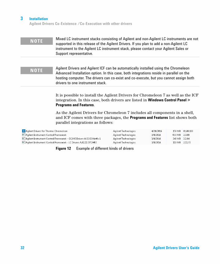
It is possible to install the Agilent Drivers for Chromeleon 7 as well as the ICF integration. In this case, both drivers are listed in Windows Control Panel > Programs and Features.
As the Agilent Drivers for Chromeleon 7 includes all components in a shell, and ICF comes with three packages, the Programs and Features list shows both parallel integrations as follows:
Figure 12 Example of different kinds of drivers
NOTE Mixed LC instrument stacks consisting of Agilent and non-Agilent LC instruments are not supported in this release of the Agilent Drivers. If you plan to add a non-Agilent LC instrument to the Agilent LC instrument stack, please contact your Agilent Sales or Support representative.
NOTE Agilent Drivers and Agilent ICF can be automatically installed using the Chromeleon Advanced Installation option. In this case, both integrations reside in parallel on the hosting computer. The drivers can co-exist and co-execute, but you cannot assign both drivers to one instrument stack.
32 Agilent Drivers User's Guide
Agilent Drivers User's Guide
4Configuring the Agilent Drivers in the Chromeleon Instrument ConfigurationConfigure your Agilent LC 34Create a Configuration Report 41Device and Signal Names 42Name appearance in the Chromeleon Console 44
This chapter gives you step-by-step instructions for configuring the Agilent Drivers in Chromeleon.
33Agilent Technologies
4 Configuring the Agilent Drivers in the Chromeleon Instrument ConfigurationConfigure your Agilent LC
Configure your Agilent LC
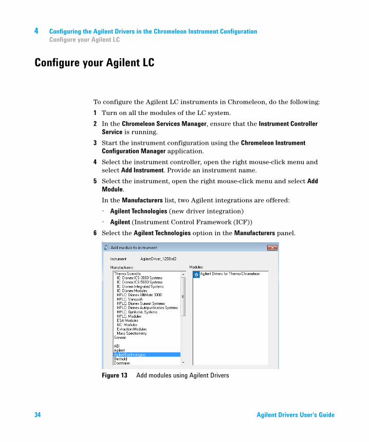
To configure the Agilent LC instruments in Chromeleon, do the following:
1 Turn on all the modules of the LC system.
2 In the Chromeleon Services Manager, ensure that the Instrument Controller Service is running.
3 Start the instrument configuration using the Chromeleon Instrument Configuration Manager application.
4 Select the instrument controller, open the right mouse-click menu and select Add Instrument. Provide an instrument name.
5 Select the instrument, open the right mouse-click menu and select Add Module.
In the Manufacturers list, two Agilent integrations are offered:
• Agilent Technologies (new driver integration)
• Agilent (Instrument Control Framework (ICF))
6 Select the Agilent Technologies option in the Manufacturers panel.
Figure 13 Add modules using Agilent Drivers
34 Agilent Drivers User's Guide
Configuring the Agilent Drivers in the Chromeleon Instrument Configuration 4Configure your Agilent LC
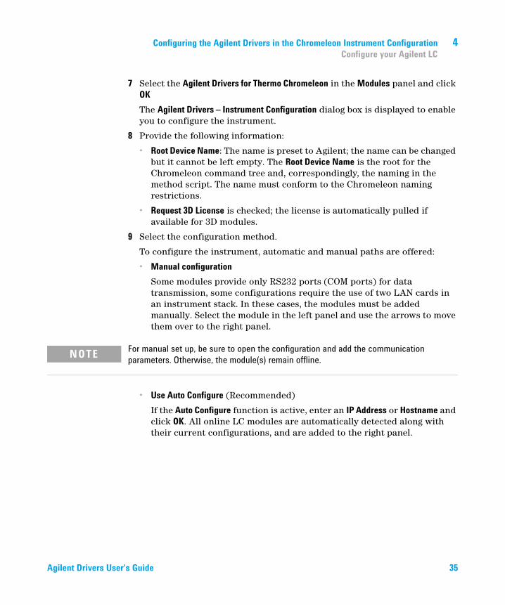
7 Select the Agilent Drivers for Thermo Chromeleon in the Modules panel and click OK
The Agilent Drivers – Instrument Configuration dialog box is displayed to enable you to configure the instrument.
8 Provide the following information:
• Root Device Name: The name is preset to Agilent; the name can be changed but it cannot be left empty. The Root Device Name is the root for the Chromeleon command tree and, correspondingly, the naming in the method script. The name must conform to the Chromeleon naming restrictions.
• Request 3D License is checked; the license is automatically pulled if available for 3D modules.
9 Select the configuration method.
To configure the instrument, automatic and manual paths are offered:
• Manual configuration
Some modules provide only RS232 ports (COM ports) for data transmission, some configurations require the use of two LAN cards in an instrument stack. In these cases, the modules must be added manually. Select the module in the left panel and use the arrows to move them over to the right panel.
• Use Auto Configure (Recommended)
If the Auto Configure function is active, enter an IP Address or Hostname and click OK. All online LC modules are automatically detected along with their current configurations, and are added to the right panel.
NOTE For manual set up, be sure to open the configuration and add the communication parameters. Otherwise, the module(s) remain offline.
Agilent Drivers User's Guide 35

4 Configuring the Agilent Drivers in the Chromeleon Instrument ConfigurationConfigure your Agilent LC
Figure 14 Autoconfiguration
Figure 15 Autoconfiguration result
Cluster Support:
The Agilent LC system offers the possibility to cluster dedicated modules; for example, two DADs can be clustered to form the High Dynamic Range Cluster (HDR). Cluster configurations are detected during autoconfiguration, and possible cluster configurations appear as active options on the right of the Edit automatic configuration dialog box.
10 If clustering is not required, click Close to proceed with the configuration of an unclustered system.
OR
Enter the Configure <Name> Cluster dialog box and specify the required cluster settings.
36 Agilent Drivers User's Guide
Configuring the Agilent Drivers in the Chromeleon Instrument Configuration 4Configure your Agilent LC
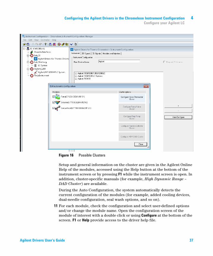
Figure 16 Possible Clusters
Setup and general information on the cluster are given in the Agilent Online Help of the modules, accessed using the Help button at the bottom of the instrument screen or by pressing F1 while the instrument screen is open. In addition, cluster-specific manuals (for example, High Dynamic Range – DAD Cluster) are available.
During the Auto Configuration, the system automatically detects the current configuration of the modules (for example, added cooling devices, dual-needle configuration, seal wash options, and so on).
11 For each module, check the configuration and select user-defined options and/or change the module name. Open the configuration screen of the module of interest with a double click or using Configure at the bottom of the screen. F1 or Help provide access to the driver help file.
Agilent Drivers User's Guide 37
4 Configuring the Agilent Drivers in the Chromeleon Instrument ConfigurationConfigure your Agilent LC
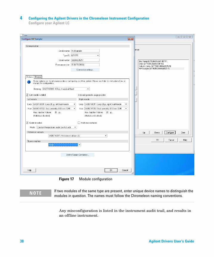
Figure 17 Module configuration
Any misconfiguration is listed in the instrument audit trail, and results in an offline instrument.
NOTE If two modules of the same type are present, enter unique device names to distinguish the modules in question. The names must follow the Chromeleon naming conventions.
38 Agilent Drivers User's Guide
Configuring the Agilent Drivers in the Chromeleon Instrument Configuration 4Configure your Agilent LC
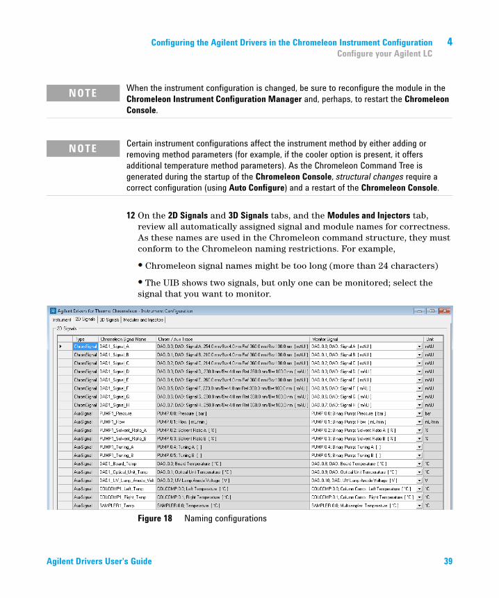
12 On the 2D Signals and 3D Signals tabs, and the Modules and Injectors tab, review all automatically assigned signal and module names for correctness. As these names are used in the Chromeleon command structure, they must conform to the Chromeleon naming restrictions. For example,
Chromeleon signal names might be too long (more than 24 characters)
The UIB shows two signals, but only one can be monitored; select the signal that you want to monitor.
Figure 18 Naming configurations
NOTE When the instrument configuration is changed, be sure to reconfigure the module in the Chromeleon Instrument Configuration Manager and, perhaps, to restart the Chromeleon Console.
NOTE Certain instrument configurations affect the instrument method by either adding or removing method parameters (for example, if the cooler option is present, it offers additional temperature method parameters). As the Chromeleon Command Tree is generated during the startup of the Chromeleon Console, structural changes require a correct configuration (using Auto Configure) and a restart of the Chromeleon Console.
Agilent Drivers User's Guide 39
4 Configuring the Agilent Drivers in the Chromeleon Instrument ConfigurationConfigure your Agilent LC
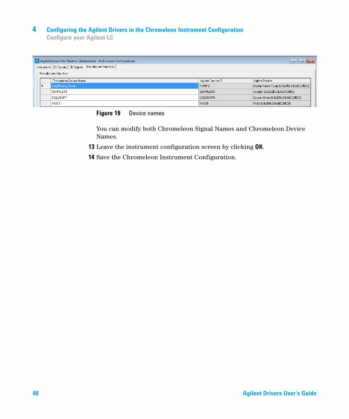
Figure 19 Device names
You can modify both Chromeleon Signal Names and Chromeleon Device Names.
13 Leave the instrument configuration screen by clicking OK.
14 Save the Chromeleon Instrument Configuration.
40 Agilent Drivers User's Guide
Configuring the Agilent Drivers in the Chromeleon Instrument Configuration 4Create a Configuration Report
Create a Configuration Report
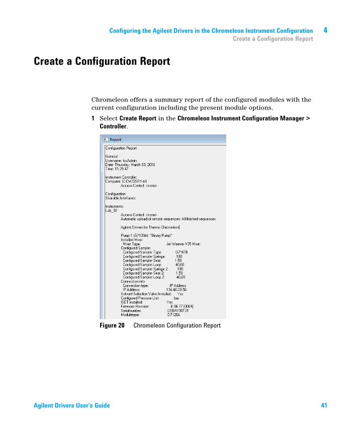
Chromeleon offers a summary report of the configured modules with the current configuration including the present module options.
1 Select Create Report in the Chromeleon Instrument Configuration Manager > Controller.
Figure 20 Chromeleon Configuration Report
Agilent Drivers User's Guide 41
4 Configuring the Agilent Drivers in the Chromeleon Instrument ConfigurationDevice and Signal Names
Device and Signal Names
The Chromeleon Instrument Configuration Editor offers access to the module names and signal names.
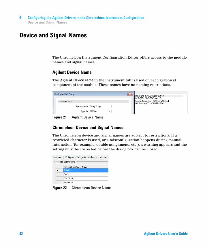
Agilent Device NameThe Agilent Device name in the instrument tab is used on each graphical component of the module. These names have no naming restrictions.
Figure 21 Agilent Device Name
Chromeleon Device and Signal NamesThe Chromeleon device and signal names are subject to restrictions. If a restricted character is used, or a misconfiguration happens during manual interaction (for example, double assignments etc.), a warning appears and the setting must be corrected before the dialog box can be closed.
Figure 22 Chromeleon Device Name
42 Agilent Drivers User's Guide
Configuring the Agilent Drivers in the Chromeleon Instrument Configuration 4Device and Signal Names
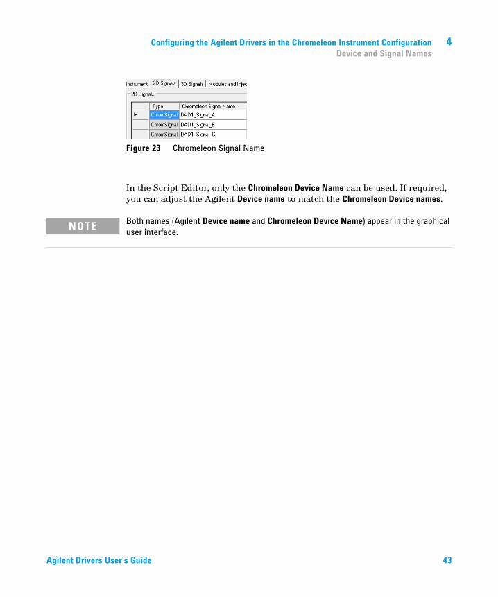
Figure 23 Chromeleon Signal Name
In the Script Editor, only the Chromeleon Device Name can be used. If required, you can adjust the Agilent Device name to match the Chromeleon Device names.
NOTE Both names (Agilent Device name and Chromeleon Device Name) appear in the graphical user interface.
Agilent Drivers User's Guide 43
4 Configuring the Agilent Drivers in the Chromeleon Instrument ConfigurationName appearance in the Chromeleon Console
Name appearance in the Chromeleon Console
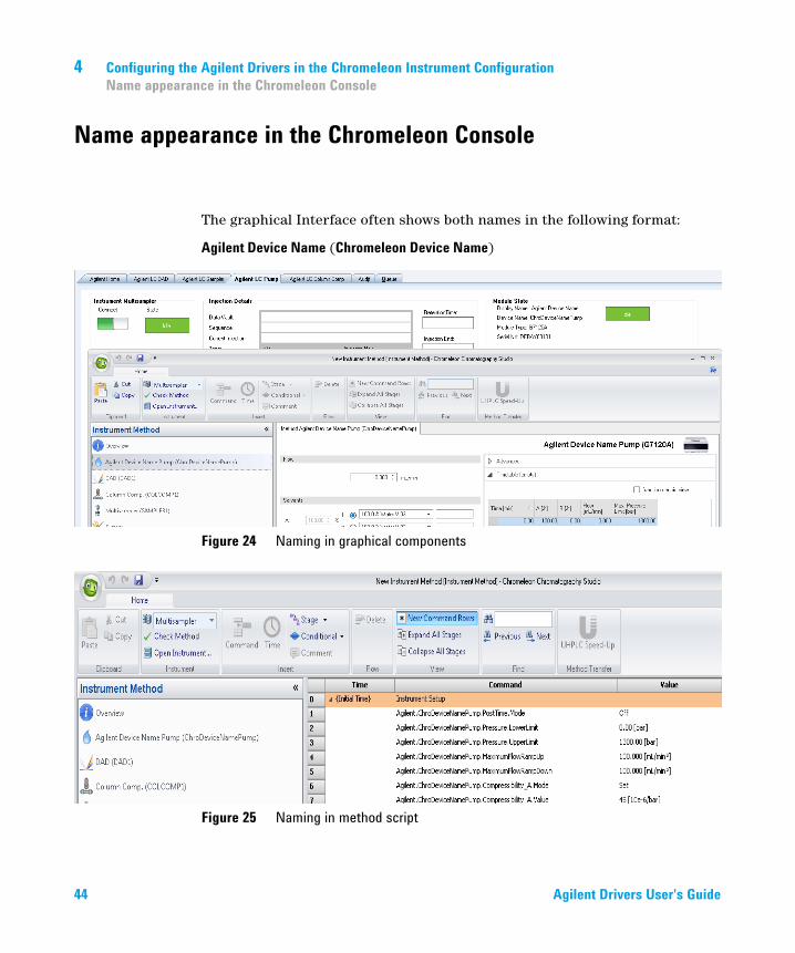
The graphical Interface often shows both names in the following format:
Agilent Device Name (Chromeleon Device Name)
Figure 24 Naming in graphical components
Figure 25 Naming in method script
44 Agilent Drivers User's Guide
Agilent Drivers User's Guide
5Getting StartedDirect Control of the Instrument 46
“Agilent Home” ePanel 46Module ePanels 50
Setting Up an Instrument Method 53Additional Information about the Instrument Method 54Graphical Instrument Method versus Instrument Method Script 56Special Information about the Command Tree, Instrument Method Commands and Method Script 60
Running Injections 63LC System 64
This chapter gives you the necessary information to allow you to start working with the Agilent Drivers for Chromeleon 7.
45Agilent Technologies

5 Getting StartedDirect Control of the Instrument
Direct Control of the Instrument
Agilent Drivers for Thermo Scientific Chromeleon (Agilent Drivers) offer two ways to control the instrument:
• “Agilent Home” ePanel
• Module ePanels
“Agilent Home” ePanelThe Agilent Home ePanel accesses the LC Status Dashboard which displays the status of each module in individual tiles, featuring the current parameter values for the module.
Figure 26 LC status dashboard with Audit Trail
46 Agilent Drivers User's Guide
Getting Started 5Direct Control of the Instrument
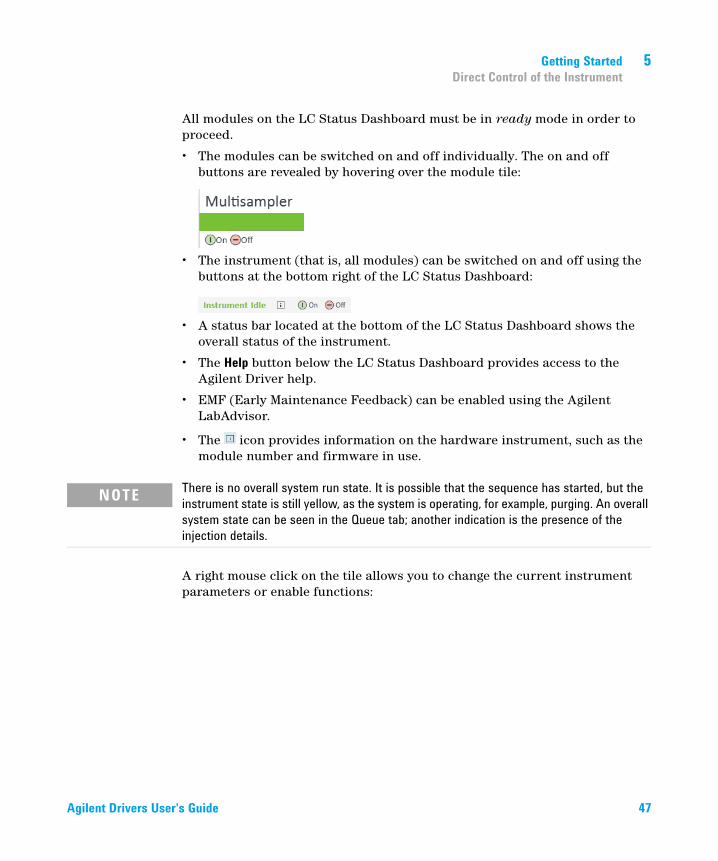
All modules on the LC Status Dashboard must be in ready mode in order to proceed.
• The modules can be switched on and off individually. The on and off buttons are revealed by hovering over the module tile:
• The instrument (that is, all modules) can be switched on and off using the buttons at the bottom right of the LC Status Dashboard:
• A status bar located at the bottom of the LC Status Dashboard shows the overall status of the instrument.
• The Help button below the LC Status Dashboard provides access to the Agilent Driver help.
• EMF (Early Maintenance Feedback) can be enabled using the Agilent LabAdvisor.
• The icon provides information on the hardware instrument, such as the module number and firmware in use.
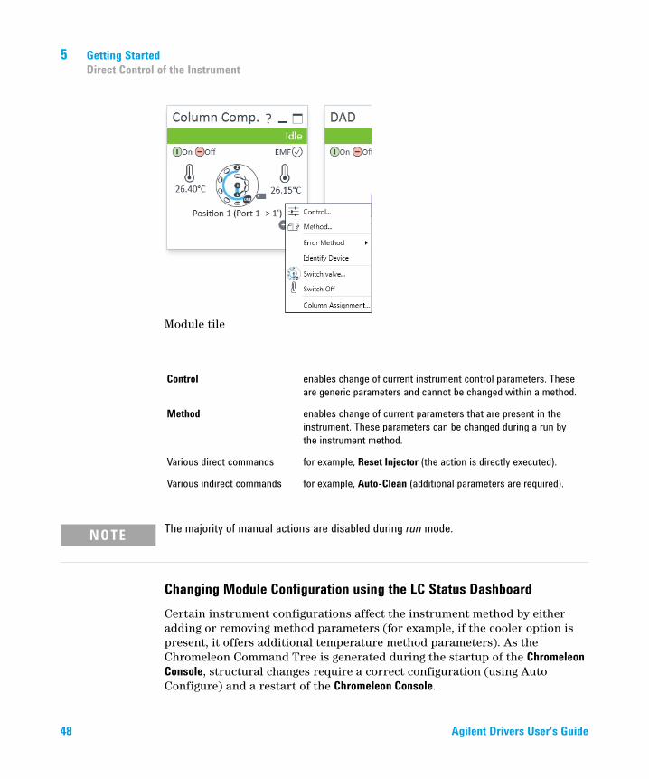
A right mouse click on the tile allows you to change the current instrument parameters or enable functions:
NOTE There is no overall system run state. It is possible that the sequence has started, but the instrument state is still yellow, as the system is operating, for example, purging. An overall system state can be seen in the Queue tab; another indication is the presence of the injection details.
Agilent Drivers User's Guide 47
5 Getting StartedDirect Control of the Instrument
Module tile
Changing Module Configuration using the LC Status DashboardCertain instrument configurations affect the instrument method by either adding or removing method parameters (for example, if the cooler option is present, it offers additional temperature method parameters). As the Chromeleon Command Tree is generated during the startup of the Chromeleon Console, structural changes require a correct configuration (using Auto Configure) and a restart of the Chromeleon Console.
Control enables change of current instrument control parameters. These are generic parameters and cannot be changed within a method.
Method enables change of current parameters that are present in the instrument. These parameters can be changed during a run by the instrument method.
Various direct commands for example, Reset Injector (the action is directly executed).
Various indirect commands for example, Auto-Clean (additional parameters are required).
NOTE The majority of manual actions are disabled during run mode.
48 Agilent Drivers User's Guide
Getting Started 5Direct Control of the Instrument
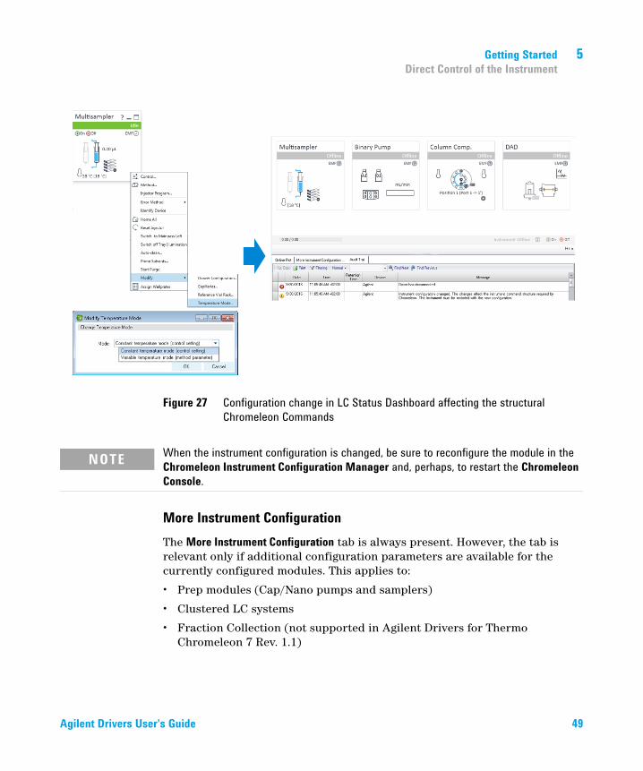
Figure 27 Configuration change in LC Status Dashboard affecting the structural Chromeleon Commands
More Instrument ConfigurationThe More Instrument Configuration tab is always present. However, the tab is relevant only if additional configuration parameters are available for the currently configured modules. This applies to:
• Prep modules (Cap/Nano pumps and samplers)
• Clustered LC systems
• Fraction Collection (not supported in Agilent Drivers for Thermo Chromeleon 7 Rev. 1.1)
NOTE When the instrument configuration is changed, be sure to reconfigure the module in the Chromeleon Instrument Configuration Manager and, perhaps, to restart the Chromeleon Console.
Agilent Drivers User's Guide 49
5 Getting StartedDirect Control of the Instrument
Module ePanelsIn addition to the "Agilent Home" ePanels, customizable ePanels are available per module class (pump, sampler, column compartment, DAD, FLD, RID, VWD). They are automatically present in the Chromeleon Console. These ePanels are customizable, and can be edited. The ePanels for the Agilent Drivers are present in the ePanel pool for Chromeleon, labeled Agilent LC <module>.
Customization of the module ePanels is possible for
• any method parameter
• all direct actions, for example,
• ON/OFF for pumps, lamps, coolers,
• Balance (Detectors)
• Reject (sampler)
Customization is not possible for indirect actions requiring additional parameters (for example, priming).
As a module ePanel can serve several modules of a module class, the control parameters present on the ePanel may not all be relevant for a particular module. For example, Multisamplers offer smart overlap for dual needle operations in addition to high throughput for single needle configuration. Parameters that are not relevant for the configured needle operation are disabled.
Agilent LC SamplerDuring acquisition, the correct values of Volume and Injection location are displayed in the ePanel, but cannot be changed. In the Idle state, the latest values of Volume and Injection location are displayed.
NOTE The ePanels for the previous native driver integration are called Agilent <module>. It is not possible to use ePanels from the native driver integration for the Agilent Drivers or vice versa, and neither is a mix of these ePanels possible.
NOTE The ePanel property enable if is used in the ePanel to display only current, relevant parameters. If a parameter is not accessible in the first instance, but is present in the module, switch the parameter on in the module's Dashboard panel.
50 Agilent Drivers User's Guide

Getting Started 5Direct Control of the Instrument
A temperature range for the thermostatted cooler is set. In the case of the Multisampler, a fixed range of +/- 5 degree is given; therefore, the range information is not given, nor is the parameter offered.
Agilent LC PumpFor the pumps, the bottle filling, eluent information is display only; it cannot be set in the ePanel. Use the right mouse click on LC status dashboard pump tile. The panels reflect the current values once enabled.
The ePanel always offers four solvent channels; depending on the pump, only the available channels are accessible.
The solvent/equate values are read only. Agilent offers pumps with premixed solvents, some are predefined by the system, the solvent names can be changed using the LC status dashboard only, with a right mouse-click on Method.
Binary pumps with solvent selection valve (SSV) use channels A and B only; channels C and D are not used. The channel names A1/A2, B1/B2 with their assigned solvent names cannot be displayed. As only one channel A or B is accessible at a time, the ePanel displays A and B (not A1, B1) and both entered solvent names. In order to identify the active pump channel, you can put the valve position on the ePanel.
Agilent LC <Detectors>When you choose Lamp OFF, both lamps are switched off.
When you are creating the ePanel, use both lamps on required for acquisition (command: lamp_required_for_run) and Lamp Status (command: UV_Lamp, property: UVLampState).
Manual parameter changes during a runChromeleon ePanels allow parameters to be changed during the execution of a run. Each manual change has to be approved and is documented in the audit trail. This interaction is allowed on the module ePanels, but not the LC Status Dashboard.
Agilent Drivers User's Guide 51

5 Getting StartedDirect Control of the Instrument
Figure 28 Audit Trail, manual change accepted
Some instrument parameters cannot be changed during a run; these on-the-fly changes are rejected. The audit trail captures the attempt of the change and its rejection, and the parameters remain unchanged.
Figure 29 Audit Trail, manual change rejected
52 Agilent Drivers User's Guide

Getting Started 5Setting Up an Instrument Method
Setting Up an Instrument Method
Use the Chromeleon Instrument Method Wizard to generate an Instrument Method.
1 Start the Chromeleon Instrument Method Wizard.
2 Enter a run time for the Chromeleon Instrument Method.
For this first release, all diagnostic channels are enabled as part of the instrument method. They can be viewed and disabled (if required) in the method script.
3 Click Next.
The Chromeleon Instrument Method Wizard offers the module method screens sequentially. The values present in the screens are the Agilent Default Method parameters.
Each method window offers the main parameters on the left; the panel on the right offers:
• Timetables
• Advanced Setpoints
• Special Features such as ISET (Intelligent System Emulation Technology), Injector Path Cleaning, etc.
One window offers the pre-treatment parameters. By inserting lines, it is possible to specify special injection procedures that are executed before the sample is injected into the system.
4 Be sure to enable, for example, required solvent channels by marking the corresponding check boxes.
5 For detector signals (DAD, MWD, VWD, FLD, RID) ensure that Acquire is checked for the signals of interest.
6 Ensure that the setting Lamps on for acquisition is checked if the lamp is required for the method.
NOTE The stop time for the Agilent modules is automatically synchronized with the run time for the Chromeleon method. The corresponding field for the method parameter is not accessible.
Agilent Drivers User's Guide 53
5 Getting StartedSetting Up an Instrument Method
This setting also allows the instrument to reach a ready state if a lamp is not switched on. In particular running combinations for DAD/FLD where only one detector is used, this setting is of interest to save lamp burn time.
Volume and Location are defined in the sequence only. It is possible to add Volume and Location manually in the method script as Inject Command parameters; both values need to be supplied (volume and location).
7 Enter a comment and description as required and click Finish to complete the wizard.
8 In the method script, verify that there is an Acquisition ON (AcqOn) command for each auxiliary and chromatographic signal in the Start Run stage, and that each one is cleared (AcqOff) in the Stop Run stage.
Starting with the Agilent Drivers for Thermo Chromeleon 7 Rev. 1.1, the Method check is back, similar to the Native Driver Chromeleon integration. A consistency check for Agilent methods, for example, that the settings in the method are useful or correct, is executed. This consistency check was not available in the ICF integration.
Additional Information about the Instrument Method
Run Time/Stop TimeChromeleon specifies the Run Time as a general part of the method, while the Agilent modules method windows offer a Stoptime and a Posttime per module. The module Stoptime has been disabled and the Chromeleon Run Time is automatically applied to all modules present in the method.
54 Agilent Drivers User's Guide

Getting Started 5Setting Up an Instrument Method
Figure 30 Agilent Module Stoptime (left) and Chromeleon Run Time (right)
Automatic Extension of Run Time due to Timetable SetupThe specified Run Time in the general settings of a Chromeleon method is automatically extended in the following cases:
• if a module Timetable is specified to be longer then the Run Time;
• if the pump Timetable is automatically adjusted based on the automatic calculation of the solvent gradients due to special features such as ISET (Intelligent System Emulation Technology).
The adjusted Run Time can be seen in the overview of the instrument method and in the Time steps in the method script.
Injection Volume HandlingInjection volume and location are, in general, specified in the sequence; therefore, the samplers do not offer the injection volume as a parameter entry.
Agilent Drivers User's Guide 55
5 Getting StartedSetting Up an Instrument Method
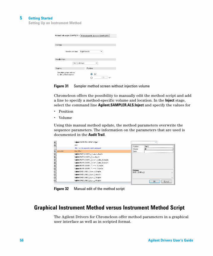
Figure 31 Sampler method screen without injection volume
Chromeleon offers the possibility to manually edit the method script and add a line to specify a method-specific volume and location. In the Inject stage, select the command line Agilent.SAMPLER.ALS.Inject and specify the values for
• Position
• Volume
Using this manual method update, the method parameters overwrite the sequence parameters. The information on the parameters that are used is documented in the Audit Trail.
Figure 32 Manual edit of the method script
Graphical Instrument Method versus Instrument Method ScriptThe Agilent Drivers for Chromeleon offer method parameters in a graphical user interface as well as in scripted format.
56 Agilent Drivers User's Guide
Getting Started 5Setting Up an Instrument Method
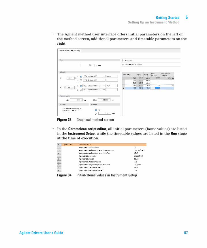
• The Agilent method user interface offers initial parameters on the left of the method screen, additional parameters and timetable parameters on the right.
Figure 33 Graphical method screen
• In the Chromeleon script editor, all initial parameters (home values) are listed in the Instrument Setup, while the timetable values are listed in the Run stage at the time of execution.
Figure 34 Initial/Home values in Instrument Setup
Agilent Drivers User's Guide 57

5 Getting StartedSetting Up an Instrument Method
Figure 35 Timetable values in the Run stage
Commands in the Command Tree and Script EditorThe Command Tree and the Script Editor (available using the Script Editor link in the navigation pane) provide a structured list of the parameters of the method. The command includes the naming and section in which the parameter is present in the graphical method interface. The following naming convention for instrument parameters is used:
RootNode.Device.Feature.Parameter[_Detail]
for example, Agilent.COLCOMP1.EnableAnalysis.MaximumDeviationLeft
Figure 36 Graphical method screen — parameter
58 Agilent Drivers User's Guide
Getting Started 5Setting Up an Instrument Method
Figure 37 Method script — grouped parameters follow the graphical method screen
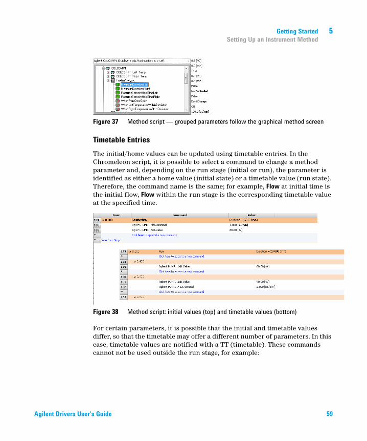
Timetable EntriesThe initial/home values can be updated using timetable entries. In the Chromeleon script, it is possible to select a command to change a method parameter and, depending on the run stage (initial or run), the parameter is identified as either a home value (initial state) or a timetable value (run state). Therefore, the command name is the same; for example, Flow at initial time is the initial flow, Flow within the run stage is the corresponding timetable value at the specified time.
Figure 38 Method script: initial values (top) and timetable values (bottom)
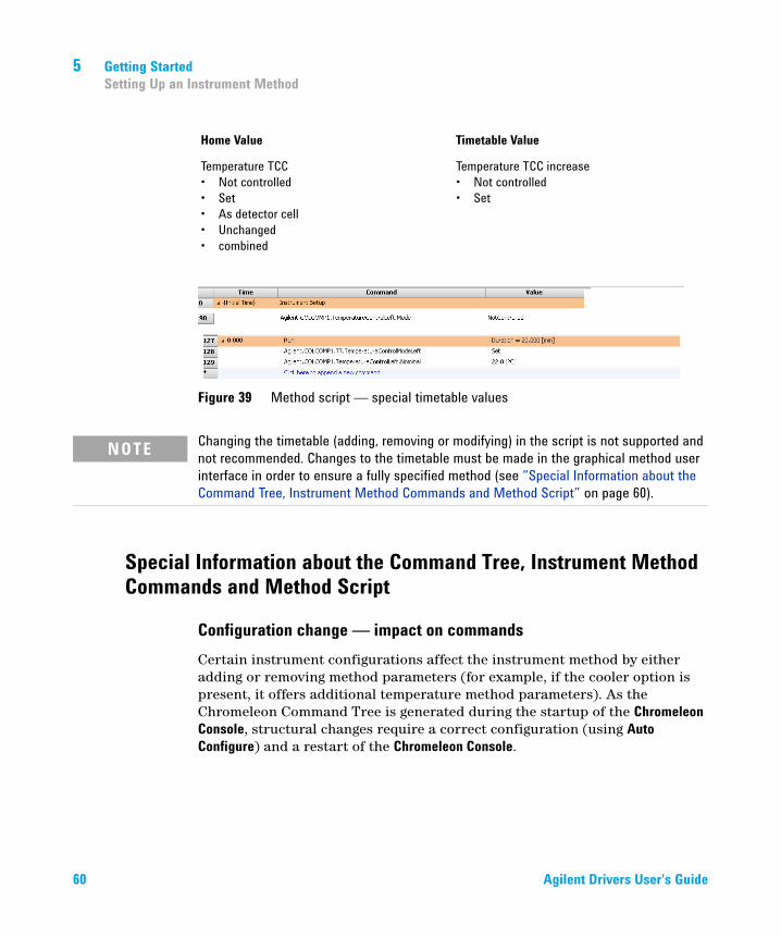
For certain parameters, it is possible that the initial and timetable values differ, so that the timetable may offer a different number of parameters. In this case, timetable values are notified with a TT (timetable). These commands cannot not be used outside the run stage, for example:
Agilent Drivers User's Guide 59
5 Getting StartedSetting Up an Instrument Method
Figure 39 Method script — special timetable values
Special Information about the Command Tree, Instrument Method Commands and Method Script
Configuration change — impact on commandsCertain instrument configurations affect the instrument method by either adding or removing method parameters (for example, if the cooler option is present, it offers additional temperature method parameters). As the Chromeleon Command Tree is generated during the startup of the Chromeleon Console, structural changes require a correct configuration (using Auto Configure) and a restart of the Chromeleon Console.
Home Value Timetable Value
Temperature TCC• Not controlled• Set• As detector cell• Unchanged• combined
Temperature TCC increase• Not controlled• Set
NOTE Changing the timetable (adding, removing or modifying) in the script is not supported and not recommended. Changes to the timetable must be made in the graphical method user interface in order to ensure a fully specified method (see “Special Information about the Command Tree, Instrument Method Commands and Method Script” on page 60).
60 Agilent Drivers User's Guide

Getting Started 5Setting Up an Instrument Method
Command tree groupingIn general, the command tree/Instrument Method commands follow the structure of the graphical interface. However, different modules may place the same command at a different position in the graphical method interface, for example:
Samplers The Sample Flush Out Factor is present in High Throughput for all samplers, even though mature samplers list this field in the Auxiliary or Advanced method parameters.
NOTE When the instrument configuration is changed, be sure to reconfigure the module in the Chromeleon Instrument Configuration Manager and, perhaps, to restart the Chromeleon Console.
Agilent Drivers User's Guide 61

5 Getting StartedSetting Up an Instrument Method
Figure 40 Example of parameter grouping
Value Ranges for CommandsIf a parameter value range (min./max.) depends on the configured options or a specific method setup, the script offers the maximum range, because the Agilent method interface uses built-in intelligence to determine these dependencies. Therefore, the graphical method interface may offer a smaller value range than is allowed in the scripted method range.
For example:
• G2258A Dual Loop Sampler fill loop with overfill factor
he graphic method screen restricts the overfill factor, while the method script, allows a maximum overfill of 100.
Figure 41 Restriction in graphical method interface
62 Agilent Drivers User's Guide
Getting Started 5Running Injections
Running Injections
This chapter provides additional information on the execution of injections and sequences using the Agilent Drivers for Chromeleon 7.
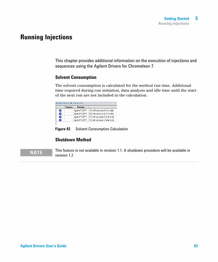
Solvent ConsumptionThe solvent consumption is calculated for the method run time. Additional time required during run initiation, data analysis and idle time until the start of the next run are not included in the calculation.
Figure 42 Solvent Consumption Calculation
Shutdown Method
NOTE This feature is not available in revision 1.1. A shutdown procedure will be available in revision 1.2
Agilent Drivers User's Guide 63

5 Getting StartedLC System
LC System
Overlapping Injection/Smart OverlapIn the sequence, all injections that use overlapped injection/smart overlap must use the same method. Where different methods are specified, the sequence continues, but the overlap of the injection is ignored.
During the execution of the sequence, the current sequence line in use and the next sequence line cannot be altered or another injection be added between these two lines.
Important restrictions for using Pretreatment/Injector Programs with Overlapped Injection:
• Overlapped Injection can handle pre-injection tasks but not post-injection tasks. This is because the next sample is being prepared for injection during the current injection.
• Some injector program commands, such as INJECT, cannot be used with Overlapped Injection. For details, refer to the help for the specific command.
Vial locationThe sample position addressing in Chromeleon requires unique location identification. As Agilent offers ranges of vial plates and well plates offering different configurations (for example, 2 × 50 vial tray and external tray) the addressing needs to be applicable to these configuration. In order to achieve unique location, you must specify the vial location in the sequence with Vial:x (where x is the location).
The following schema is used for vial and plate locations throughout:
Position Type Agilent Drivers Integration Example
Vial Vial:1 . n Vial:1
Wellplate P<n>:<x><y> P1:A1
Drawer(Multisampler only)
D<n>F/B:<x><y> D1F:A1
64 Agilent Drivers User's Guide
Getting Started 5LC System
where
• <n> is the plate or drawer number
• <x> and <y> are the coordinates on the plate
• F and B are the position of the plate in the drawer (Front or Back)
This schema is used for vial and wellplate locations in all places:
• sequence wizard
• method script
• ePanels
Agilent Drivers User's Guide 65

5 Getting StartedLC System
66 Agilent Drivers User's Guide

Agilent Drivers User's Guide
6Troubleshooting
This chapter describes what to do when something goes wrong.
67Agilent Technologies
6 TroubleshootingInstrument Errors
Instrument Errors
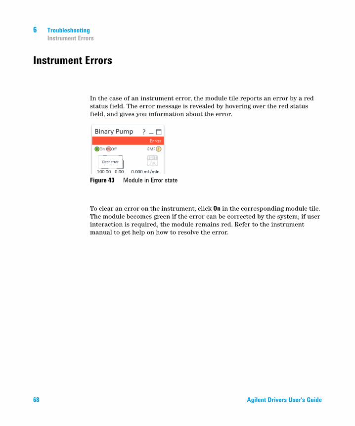
In the case of an instrument error, the module tile reports an error by a red status field. The error message is revealed by hovering over the red status field, and gives you information about the error.
Figure 43 Module in Error state
To clear an error on the instrument, click On in the corresponding module tile. The module becomes green if the error can be corrected by the system; if user interaction is required, the module remains red. Refer to the instrument manual to get help on how to resolve the error.
68 Agilent Drivers User's Guide

Troubleshooting 6Verify correct installation of Agilent Drivers
Verify correct installation of Agilent Drivers
Run the Software Verification tool (SVT) to verify the correct installation of software components as outlined in section “Software Verification” on page 26. If the SVT reports missing file, reinstall the Agilent Drivers in Start > ControlPanel > Software and Features.
Agilent Drivers User's Guide 69
6 TroubleshootingInformation required for Troubleshooting
Information required for Troubleshooting
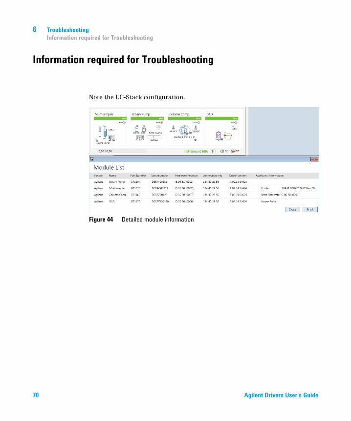
Note the LC-Stack configuration.
Figure 44 Detailed module information
70 Agilent Drivers User's Guide
Troubleshooting 6Information required for Troubleshooting
Collect the Agilent Instrument Driver Log Files
The Driver log files help Agilent to investigate issues. A maximum of 200 files are stored before the files are overwritten.
Note the date and the time when the error occurred.
1 64-Bit Windows Systems: Locate the folder C:\Program Files (x86)\Agilent Technologies\Agilent Drivers for Thermo Chromeleon\Instrument Control Framework\Support
OR
32-Bit Windows Systems: Locate the folder C:\Program Files\Agilent Technologies\Agilent Drivers for Thermo Chromeleon\Instrument Control Framework\Support
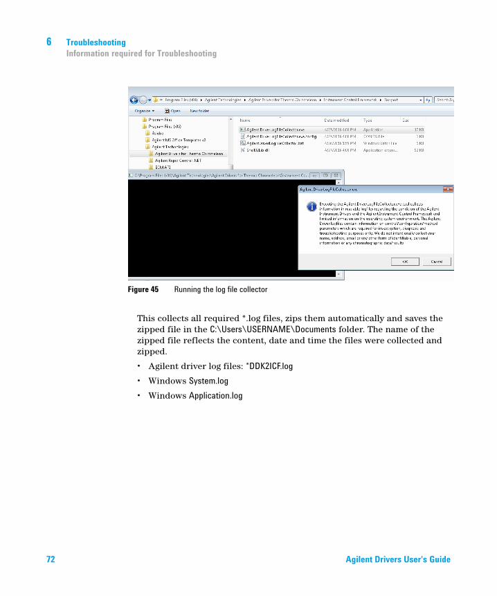
2 Execute the batch file: Agilent.DriverLogFileCollector.bat. For more details, see the dialog box during execution.
NOTE The location of the Test Application for the Agilent Driver for Thermo Chromeleon 7 differs from that of an ICF integration. If both integrations are present on your system, be sure to call and execute the correct driver log file collector.
Agilent Drivers User's Guide 71
6 TroubleshootingInformation required for Troubleshooting
This collects all required *.log files, zips them automatically and saves the zipped file in the C:\Users\USERNAME\Documents folder. The name of the zipped file reflects the content, date and time the files were collected and zipped.
• Agilent driver log files: *DDK2ICF.log
• Windows System.log
• Windows Application.log
Figure 45 Running the log file collector
72 Agilent Drivers User's Guide

Troubleshooting 6Information required for Troubleshooting
NOTE If the .zip file is empty, verify that the check box Show hidden files, folders, or drives in the folder options in the Windows Explorer is selected.
Windows Explorer Options
Agilent Drivers User's Guide 73

6 TroubleshootingInformation required for Troubleshooting
Monitor with the Test Application
You can use the Agilent Test Application to verify that the instrument is working properly outside Chromeleon. The Test Application opens a connection to the instrument without any interaction of or with the CDS.
The Test Application is part of the third party instrument control packages and is present by default.
1 Close the application you are using. In particular, if you have Agilent modules using Firmware Revision A.xx.xx, these modules can connect with one control partner only.
• Either explicitly disconnect the LC using the ePanel (recommended)
• Or, stop the Instrument Controller Services using the Chromeleon Services Manager.
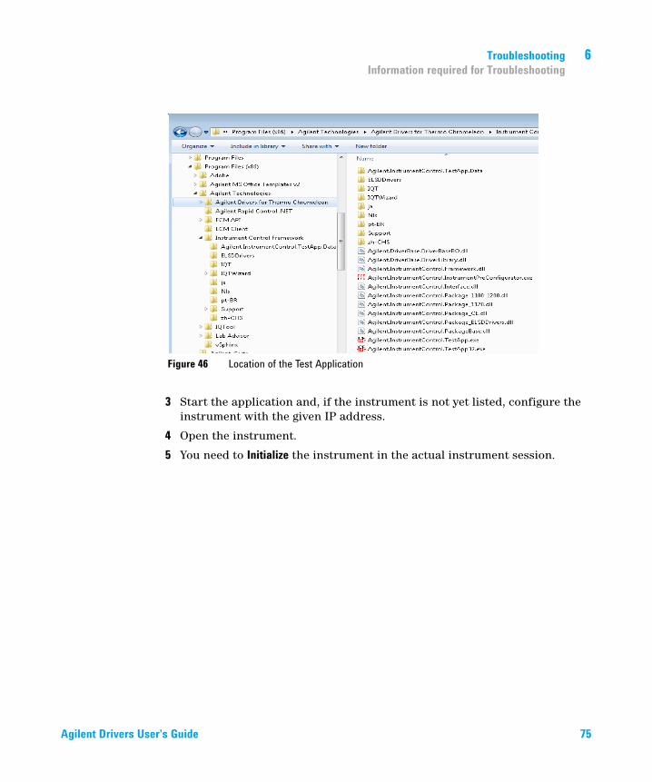
2 Using Windows Explorer, locate the file Agilent.Instrument.Control.TestApp(32).exe in the folder C:\Program Files (x86)\Agilent Technologies\Agilent Drivers for Thermo Chromeleon\Instrument Control Framework
• The Agilent.Instrument.Control.TestApp32.exe runs as a 32-bit process and all drivers are recognized.
• The Agilent.Instrument.Control.TestApp.exe runs as a 64-bit process. Not all drivers are recognized.
NOTE For the Agilent Driver for Thermo Chromeleon 7, the location of the Test Application differs from that of an ICF integration. If both integrations are on your system, ensure to call the correct Test Application.
74 Agilent Drivers User's Guide
Troubleshooting 6Information required for Troubleshooting
3 Start the application and, if the instrument is not yet listed, configure the instrument with the given IP address.
4 Open the instrument.
5 You need to Initialize the instrument in the actual instrument session.
Figure 46 Location of the Test Application
Agilent Drivers User's Guide 75

6 TroubleshootingInformation required for Troubleshooting
6 If the instrument is able to operate in the test application (click Initialize for activation) the issue is most probably related to the integration to the CDS.
7 You can set up, save and run a method to be sure that all parameters are transferred and the complete system is working. Edit the module parameters and save them.
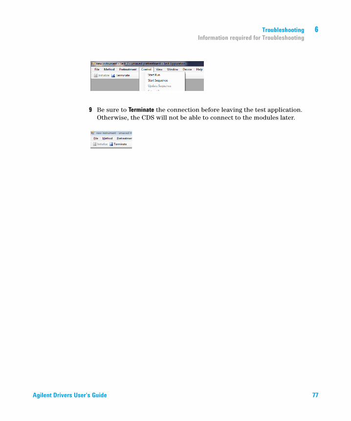
8 Run the method. (Control > Start Run)
Figure 47 Running the Test Application
76 Agilent Drivers User's Guide
Troubleshooting 6Information required for Troubleshooting
9 Be sure to Terminate the connection before leaving the test application. Otherwise, the CDS will not be able to connect to the modules later.
Agilent Drivers User's Guide 77

6 TroubleshootingInformation required for Troubleshooting
78 Agilent Drivers User's Guide

Agilent Drivers User's Guide
7Known Limitations
This chapter lists the known limitations of the current revision of the Agilent Drivers for Thermo Chromeleon 7.
79Agilent Technologies

7 Known LimitationsOnly one CDS running the Agilent Drivers is supported
Only one CDS running the Agilent Drivers is supported
You can use only one CDS or other application using Agilent Drivers per computer. A different PC is required if you want to use another CDS with the Agilent Drivers.
80 Agilent Drivers User's Guide
Known Limitations 7Diagnostic Functions are not supported
Diagnostic Functions are not supported
Agilent Drivers do not provide the functionality to access EMF counters or perform diagnostic/maintenance operations on the individual modules. Therefore, Chromeleon cannot offer any functionality for diagnostics. The Agilent Lab Advisor software is required to perform software diagnostic operations.
NOTE Modules equipped with firmware revision A.xx.xx are not able to communicate with Chromeleon and the Lab Advisor simultaneously.
Agilent Drivers User's Guide 81

7 Known LimitationsMixed module configuration of Agilent /non-Agilent LC instrumentation is not supported
Mixed module configuration of Agilent /non-Agilent LC instrumentation is not supported
This release does not support the mixing in one LC stack of modules from different vendors. The controlled LC instrument stack must consist of Agilent modules only.
82 Agilent Drivers User's Guide
Known Limitations 7Other Limitations
Other Limitations
• Only one injector is allowed per instrument.
• Manual Injection is not supported.
• Missing vials are handled slightly differently from Thermo Scientific instruments. Either the method continues to run without injection (for the current method run time) or the running queue is aborted immediately. The behavior can be controlled via the setting Ignore Missing Vessel available from the Agilent status window in the ePanel. Select Control... from the sampler’s context menu to access this setting.
• Visual display of the rack layout is not available for Agilent LC systems. The tray position of the Agilent LC shows a list of positions but no valid tray geometry, as this is not characterized by the Agilent Drivers.
• Data from ad-hoc runs (started via the handheld controller) are not collected.
• Agilent LC instruments use built-in emergency methods; therefore, emergency instrument methods in the Chromeleon queue cannot be used. Instead, these methods must be specified using the context menu in the Agilent instrument status window. Refer to the Chromeleon help or Agilent Instrument Drivers help for details.
• The commands Hold, Continue, StopFlow and Message are not available with the Agilent Drivers. These commands are treated differently, depending on the LC instrument stack:
• If a sampler is part of the instrument, Wait/Hold/Continue/StopFlow commands in the Run stage are rejected by the ready check
• If no sampler is part of the instrument, Wait/Hold/Continue/StopFlow commands in the Run stage are not rejected by the ready check
• The Monitor Baseline control, which Chromeleon offers for Data Acquisition functions, but is not supported. Chromeleon offers Monitor Baseline to allow you to manually save the online signal in an idle state or after a manual injection. As Agilent modules offer a monitor signal (outside a run) and Chromatogram signals (inside a run) that are not delivered with the same frequency, Agilent does not support this feature for manual injections to generate analytical results.
Agilent Drivers User's Guide 83
7 Known LimitationsOther Limitations
• The configuration editor offers the setup of the column plumbing as well as a table for column information (for example, description, product number etc.) for the G7116A/B Multi-Column Compartment and for the Valve-Thermostat-Cluster (VTC). The column plumbing is correctly displayed and used in the methods. The module is working in the expected setup.
The column information cannot be presented for selection in the G7116A/B graphical method interface and Valve-Thermostat-Cluster (VTC). As the column information is not offered in the GUI, the option enforce column cannot be selected.
84 Agilent Drivers User's Guide
Agilent Drivers User's Guide
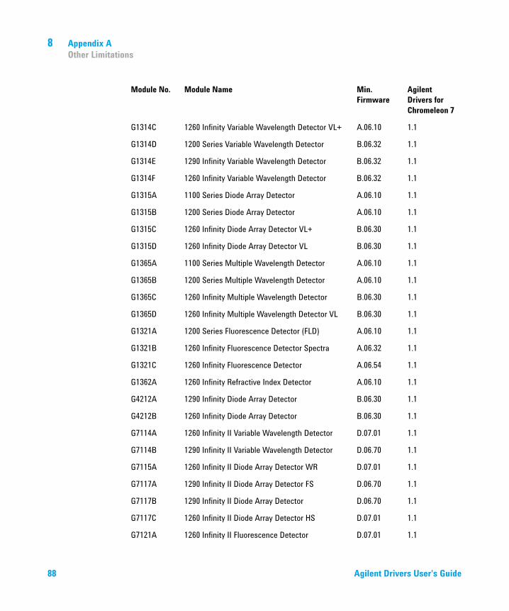
8Appendix A
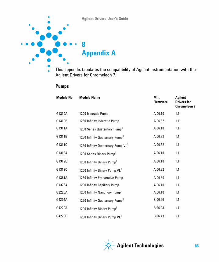
This appendix tabulates the compatibility of Agilent instrumentation with the Agilent Drivers for Chromeleon 7.
Pumps
Module No. Module Name Min. Firmware
Agilent Drivers for Chromeleon 7
G1310A 1200 Isocratic Pump A.06.10 1.1
G1310B 1260 Infinity Isocratic Pump A.06.32 1.1
G1311A 1200 Series Quaternary Pump1 A.06.10 1.1
G1311B 1260 Infinity Quaternary Pump1 A.06.32 1.1
G1311C 1260 Infinity Quaternary Pump VL1 A.06.32 1.1
G1312A 1200 Series Binary Pump1 A.06.10 1.1
G1312B 1260 Infinity Binary Pump1 A.06.10 1.1
G1312C 1260 Infinity Binary Pump VL1 A.06.32 1.1
G1361A 1260 Infinity Preparative Pump A.06.50 1.1
G1376A 1260 Infinity Capillary Pump A.06.10 1.1
G2226A 1260 Infinity Nanoflow Pump A.06.10 1.1
G4204A 1290 Infinity Quaternary Pump1 B.06.50 1.1
G4220A 1290 Infinity Binary Pump1 B.06.23 1.1
G4220B 1290 Infinity Binary Pump VL1 B.06.43 1.1
85Agilent Technologies

8 Appendix AOther Limitations
Sampling Systems
G4302A 1260 Infinity SFC Binary Pump1 A.06.32 1.1
G5611A 1260 Infinity Bio-inert Quaternary Pump1 A.06.32 1.1
G7104A 1290 Infinity II Flexible Pump1 B.06.71 1.1
G7110B 1260 Infinity II Isocratic Pump D.07.01 1.1
G7111A 1260 Infinity II Quaternary Pump VL1 D.07.01 1.1
G7111B 1260 Infinity II Quaternary Pump VL1 D.07.01 1.1
G7112B 1260 Infinity II Binary Pump1 D.07.01 1.1
G7120A 1290 Infinity II High Speed Pump1 B.06.71 1.1
G5654A 1260 Infinity II Bio-Inert Quaternary Pump1 D.07.01 1.1
Cluster
N/A Pumps marked with 1 are able to build a pump valve cluster with up to two valves of type G1160A and/or G1170A
See modules
1.1
N/A 1260 Infinity Preparative Pump Cluster with up to four G1361As
A.06.50 1.1
Module No. Module Name Min. Firmware
Agilent Drivers for Chromeleon 7
G1328A/B Manual Injector N/A No
G1330A/B Thermostat for Agilent Sampler N/A 1.1
G1313A 1100 Series Autosampler A.06.10 1.1
G1329A 1200 Series Standard Autosampler A.06.10 1.1
G1329B 1260 Infinity Standard Autosampler A.06.10 1.1
Module No. Module Name Min. Firmware
Agilent Drivers for Chromeleon 7
86 Agilent Drivers User's Guide
Appendix A 8Other Limitations
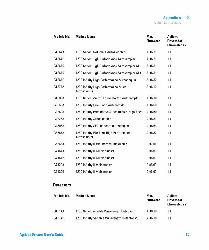
Detectors
G1367A 1100 Series Well-plate Autosampler A.06.31 1.1
G1367B 1200 Series High Performance Autosampler A.06.31 1.1
G1367C 1200 Series High Performance Autosampler SL A.06.31 1.1
G1367D 1200 Series High Performance Autosampler SL+ A.06.31 1.1
G1367E 1260 Infinity High Performance Autosampler A.06.32 1.1
G1377A 1260 Infinity High Performance Micro Autosampler
A.06.12 1.1
G1389A 1100 Series Micro Thermostatted Autosampler A.06.10 1.1
G2258A 1260 Infinity Dual-Loop Autosampler A.06.50 1.1
G2260A 1260 Infinity Preparative Autosampler (High flow) A.06.50 1.1
G4226A 1290 Infinity Autosampler A.06.31 1.1
G4303A 1260 Infinity SFC standard autosampler A.06.54 1.1
G5667A 1260 Infinity Bio-inert High Performance Autosampler
A.06.32 1.1
G5668A 1260 Infinity II Bio-inert Multisampler D.07.01 1.1
G7167A 1260 Infinity II Multisampler D.06.60 1.1
G7167B 1290 Infinity II Multisampler D.06.60 1.1
G7129A 1260 Infinity II Vialsampler D.06.60 1.1
G7129B 1290 Infinity II Vialsampler D.06.60 1.1
Module No. Module Name Min. Firmware
Agilent Drivers for Chromeleon 7
G1314A 1100 Series Variable Wavelength Detector A.06.10 1.1
G1314B 1260 Infinity Variable Wavelength Detector VL A.06.10 1.1
Module No. Module Name Min. Firmware
Agilent Drivers for Chromeleon 7
Agilent Drivers User's Guide 87
8 Appendix AOther Limitations
G1314C 1260 Infinity Variable Wavelength Detector VL+ A.06.10 1.1
G1314D 1200 Series Variable Wavelength Detector B.06.32 1.1
G1314E 1290 Infinity Variable Wavelength Detector B.06.32 1.1
G1314F 1260 Infinity Variable Wavelength Detector B.06.32 1.1
G1315A 1100 Series Diode Array Detector A.06.10 1.1
G1315B 1200 Series Diode Array Detector A.06.10 1.1
G1315C 1260 Infinity Diode Array Detector VL+ B.06.30 1.1
G1315D 1260 Infinity Diode Array Detector VL B.06.30 1.1
G1365A 1100 Series Multiple Wavelength Detector A.06.10 1.1
G1365B 1200 Series Multiple Wavelength Detector A.06.10 1.1
G1365C 1260 Infinity Multiple Wavelength Detector B.06.30 1.1
G1365D 1260 Infinity Multiple Wavelength Detector VL B.06.30 1.1
G1321A 1200 Series Fluorescence Detector (FLD) A.06.10 1.1
G1321B 1260 Infinity Fluorescence Detector Spectra A.06.32 1.1
G1321C 1260 Infinity Fluorescence Detector A.06.54 1.1
G1362A 1260 Infinity Refractive Index Detector A.06.10 1.1
G4212A 1290 Infinity Diode Array Detector B.06.30 1.1
G4212B 1260 Infinity Diode Array Detector B.06.30 1.1
G7114A 1260 Infinity II Variable Wavelength Detector D.07.01 1.1
G7114B 1290 Infinity II Variable Wavelength Detector D.06.70 1.1
G7115A 1260 Infinity II Diode Array Detector WR D.07.01 1.1
G7117A 1290 Infinity II Diode Array Detector FS D.06.70 1.1
G7117B 1290 Infinity II Diode Array Detector D.06.70 1.1
G7117C 1260 Infinity II Diode Array Detector HS D.07.01 1.1
G7121A 1260 Infinity II Fluorescence Detector D.07.01 1.1
Module No. Module Name Min. Firmware
Agilent Drivers for Chromeleon 7
88 Agilent Drivers User's Guide

Appendix A 8Other Limitations
Column Compartments
G7121B 1260 Infinity II Fluorescence Detector Spectra D.07.01 1.1
G7165A 1260 Infinity II Multi Wavelength Detector D.07.01 1.1
G4218A 1260 Infinity Evaporative Light Scattering Detector
1.3 No
G4260A 380-ELSD 25.00 1.1
G4261A 385-ELSD 25.00 1.1
G4260B 1260 Infinity II Evaporative Light Scattering Detector
30.35 1.1
G4261B 1290 Infinity Evaporative Light Scattering Detector
30.35 1.1
G7102A 1290 Infinity II Evaporative Light Scattering Detector
30.42 1.1
G7162A 1260 Infinity II Refractive Index Detector D.06.76 1.1
G7162B 1290 Infinity II Refractive Index Detector D.06.76 1.1
Cluster
HDR-DAD Cluster
2 × G4212A or 2 × G4212B or a combination of 1 × G4212A and 1 × G4212B
B.06.57 1.1
HDR-DAD Cluster
2 × G7117A or 2 × G7117B or a combination of 1 × G7117A and 1 × G7117BB
B.06.70 1.1
Module No. Module Name Min. Firmware
Agilent Drivers for Chromeleon 7
G1316A 1260 Infinity Thermostatted Column Compartment
A.06.10 1.1
G1316B 1200 Series Thermostatted Column Compartment SL
A.06.10 1.1
Module No. Module Name Min. Firmware
Agilent Drivers for Chromeleon 7
Agilent Drivers User's Guide 89
8 Appendix AOther Limitations
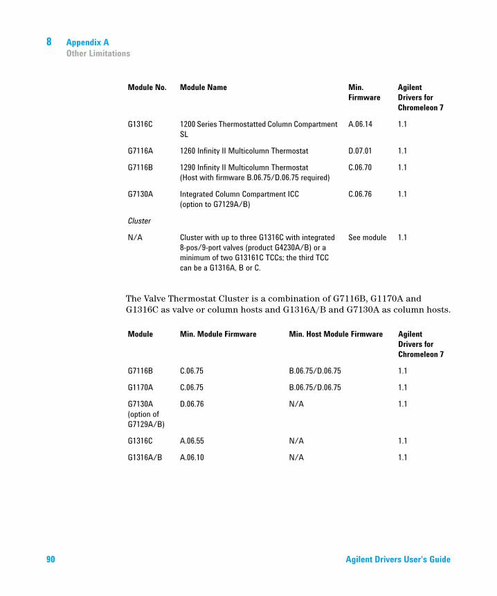
The Valve Thermostat Cluster is a combination of G7116B, G1170A and G1316C as valve or column hosts and G1316A/B and G7130A as column hosts.
G1316C 1200 Series Thermostatted Column Compartment SL
A.06.14 1.1
G7116A 1260 Infinity II Multicolumn Thermostat D.07.01 1.1
G7116B 1290 Infinity II Multicolumn Thermostat(Host with firmware B.06.75/D.06.75 required)
C.06.70 1.1
G7130A Integrated Column Compartment ICC(option to G7129A/B)
C.06.76 1.1
Cluster
N/A Cluster with up to three G1316C with integrated 8-pos/9-port valves (product G4230A/B) or a minimum of two G13161C TCCs; the third TCC can be a G1316A, B or C.
See module 1.1
Module Min. Module Firmware Min. Host Module Firmware Agilent Drivers for Chromeleon 7
G7116B C.06.75 B.06.75/D.06.75 1.1
G1170A C.06.75 B.06.75/D.06.75 1.1
G7130A (option of G7129A/B)
D.06.76 N/A 1.1
G1316C A.06.55 N/A 1.1
G1316A/B A.06.10 N/A 1.1
Module No. Module Name Min. Firmware
Agilent Drivers for Chromeleon 7
90 Agilent Drivers User's Guide

Appendix A 8Other Limitations
Quick Change Valves for Agilent LC Modules
Other Modules
Module No. Module Name Min. Firmware
Agilent Drivers for Chromeleon 7
G1157A 1200 Series 2-Position/10-Port Valve A.06.02 1.1
G1158A 1200 Series 2-Position/6-Port Valve A.06.02 1.1
G1158B 1200 Series 2-Position/6-Port Valve (600bar) A.06.02 1.1
G1159A 1200 Series 6-Position Selection Valve A.06.02 1.1
G1160A 1100 Series Multiple Purpose Switching Valve (12-Position/13-Port)
A.06.02 1.1
G1162A 1200 Series 2-Position/6-Port Micro Valve A.06.02 1.1
G1163A 1200 Series 2-Position/10-Port Micro Valve A.06.02 1.1
G1170A 1290 Infinity Valve Drive (Host required with firmware B.06.40/D.06.060)
C.06.40 1.1
Module No. Module Name Min. Firmware
Agilent Drivers for Chromeleon 7
G1390A 1100 Series Universal Interface Box (UIB) A.06.02 1.1
G1390B 1200 Infinity Series Universal Interface Box II(Host required with B.06.53 firmware)
C.06.53 1.1
G4227A 1290 Infinity Flexible Cube(Host required with B.06.52 firmware)
C.06.52 1.1
G1364A 1100 Series Automatic Fraction Collector A.06.53 No
G1364B 1260 Infinity Fraction Collector (preparative-scale)
A.06.53 No
G1364C 1260 Infinity Fraction Collector (analytical-scale) A.06.53 No
G1364D 1100 Series Micro Fraction Collector A.06.53 No
G5664A 1260 Infinity Bio-inert fraction collector AS A.06.53 No
Agilent Drivers User's Guide 91

8 Appendix AOther Limitations
Agilent LC Systems (1120 Compact, 1220 Infinity LC System, 1220 Infinity II LC System)
G4240A 1260 Infinity Chip Cube MS Interface A.06.36 No
G4301A 1260 Infinity Analytical SFC System A.03.07 1.1
Cluster
N/A Any combination of G1364A/B/C or G566A plus a fourth G1364A/B/C or G5664A for recovery can be clustered.Multiple single Fraction Collectors are not supported
See module No
Module No. Module Name Min. Firmware
Agilent Drivers for Chromeleon 7
G4286A 1120 LC Isocratic B.06.50 1.1
G4286B 1220 LC System Isocratic, Man. Inj., VWD, 600 bar
B.06.50 No
G4287A 1120 LC Isocratic with Oven and ALS B.06.50 1.1
G4287B 1220 LC Isocratic, ALS, TCC, VWD, 600 bar B.06.50 1.1
G4288A 1120 LC Gradient B.06.50 1.1
G4288B 1220 LC Gradient, Man. Inj., VWD, 600 bar B.06.50 No
G4289A 1120 LC Gradient with Oven B.06.50 1.1
G4289B 1220 LC Gradient, ALS, TCC, VWD, 600 bar B.06.50 1.1
G4290A 1120 LC Gradient with oven and ALS B.06.50 1.1
G4290B 1220 LC Gradient, ALS, Man. Inj., TCC, VWD, 600 bar
B.06.50 1.1
G4291B 1220 LC Isocratic, Man. Inj., TCC, VWD, 600 bar B.06.50 No
G4292B 1220 LC Isocratic, ALS, VWD, 600 bar B.06.50 1.1
Module No. Module Name Min. Firmware
Agilent Drivers for Chromeleon 7
92 Agilent Drivers User's Guide
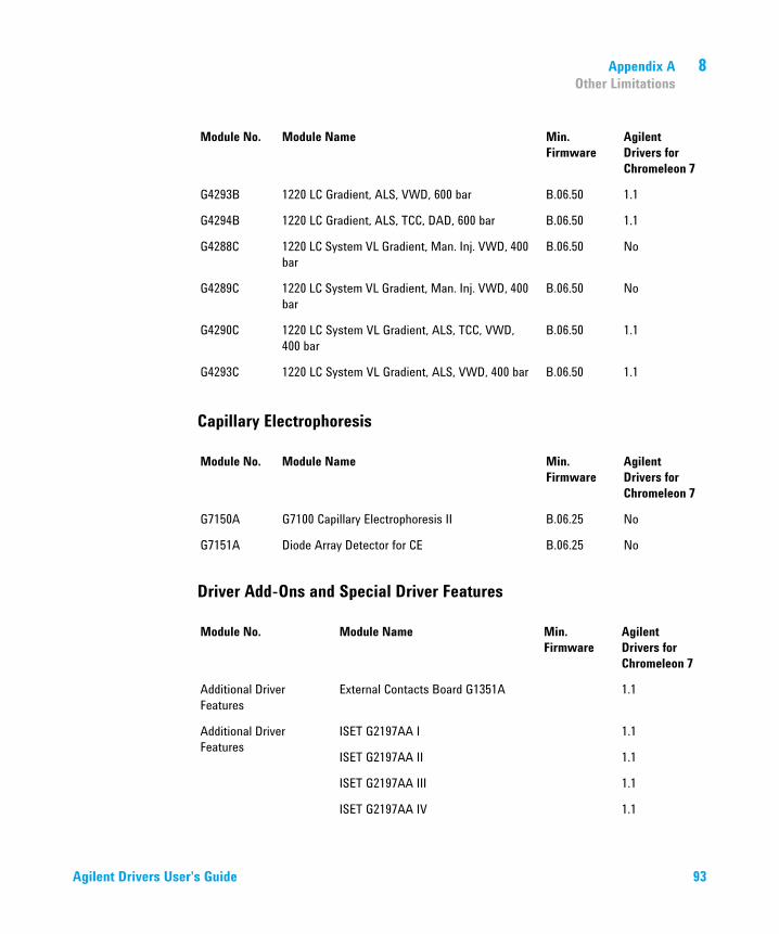
Appendix A 8Other Limitations
Capillary Electrophoresis
Driver Add-Ons and Special Driver Features
G4293B 1220 LC Gradient, ALS, VWD, 600 bar B.06.50 1.1
G4294B 1220 LC Gradient, ALS, TCC, DAD, 600 bar B.06.50 1.1
G4288C 1220 LC System VL Gradient, Man. Inj. VWD, 400 bar
B.06.50 No
G4289C 1220 LC System VL Gradient, Man. Inj. VWD, 400 bar
B.06.50 No
G4290C 1220 LC System VL Gradient, ALS, TCC, VWD, 400 bar
B.06.50 1.1
G4293C 1220 LC System VL Gradient, ALS, VWD, 400 bar B.06.50 1.1
Module No. Module Name Min. Firmware
Agilent Drivers for Chromeleon 7
G7150A G7100 Capillary Electrophoresis II B.06.25 No
G7151A Diode Array Detector for CE B.06.25 No
Module No. Module Name Min. Firmware
Agilent Drivers for Chromeleon 7
Additional Driver Features
External Contacts Board G1351A 1.1
Additional Driver Features
ISET G2197AA I 1.1
ISET G2197AA II 1.1
ISET G2197AA III 1.1
ISET G2197AA IV 1.1
Module No. Module Name Min. Firmware
Agilent Drivers for Chromeleon 7
Agilent Drivers User's Guide 93

Module No. Module Name Min. Firmware
Agilent Drivers for Chromeleon 7
Special Solutions Buffer Advisor (G5617AA) No 1.1 (Import Buffer Files)
2DLC (G2198AA) No No
Method Scouting Wizard (G2196AA) No No
Automated Purification Software (M8368/M8369AA)
No No

www.agilent.com
In This Book
This manual contains information for the installation and use of the Agilent Drivers for Thermo Chromeleon 7.
The manual describes the following:
• how to install the Agilent Drivers
• how to configure the instrument
• how to run injections
• the handling of methods
• how to migrate methods based on earlier integrations
• how to troubleshoot
© Agilent Technologies 2017
Printed in Germany 04/17
*G4098-90000**G4098-90000*G4098-90000
Agilent Technologies