Agentsheets: A Tool for Building Domain-Oriented …ralex/papers/PDF/Repenning-PhD.pdfA Tool for...
181
Agentsheets: A Tool for Building Domain-Oriented Dynamic, Visual Environments Alexander Repenning Ph.D. Dissertation CU-CS-693-93 December 1993 University of Colorado at Boulder DEPARTMENT OF COMPUTER SCIENCE
Transcript of Agentsheets: A Tool for Building Domain-Oriented …ralex/papers/PDF/Repenning-PhD.pdfA Tool for...

Agentsheets:A Tool for Building Domain-Oriented
Dynamic, Visual Environments
Alexander Repenning
Ph.D. Dissertation
CU-CS-693-93 December 1993
University of Colorado at Boulder
DEPARTMENT OF COMPUTER SCIENCE

AGENTSHEETS: A TOOL FOR BUILDING DOMAIN-ORIENTED DYNAMIC,VISUAL ENVIRONMENTS
by
ALEXANDER REPENNING
B.S., Engineering College, Brugg-Windisch, 1985
M.S., University of Colorado, 1990
A thesis submitted to the
Faculty of the Graduate School of the
University of Colorado in partial fulfillment
of the requirement for the degree of
Doctor of Philosophy
Department of Computer Science
1993
Committee:
Clayton Lewis, Chairman, Department of Computer Science
Ernesto Arias, College of Environmental Design
Wayne Citrin, Department of Computer Science and Electrical Engineering
Gerhard Fischer, Department of Computer Science
Mark Gross, College of Environmental Design
Jim Martin, Department of Computer Science
Peter Polson, Department of Psychology

AGENTSHEETS: A TOOL FOR BUILDING DOMAIN-ORIENTED DYNAMIC,VISUAL ENVIRONMENTS
Repenning, Alexander (Ph.D., Computer Science)
Thesis directed by Professor Clayton Lewis
Abstract
Cultures deal with their environments by adapting to them and simultaneously changing them. This is particularly
true for technological cultures, such as the dynamic culture of computer users. To date, the ability to change computing
environments in non-trivial ways has been dependent upon the skill of programming. Because this skill has been hard
to acquire, most computer users must adapt to computing environments created by a small number of programmers. In
response to the scarcity of programming ability, the computer science community has concentrated on producing
general-purpose tools that cover wide spectrums of applications. As a result, contemporary programming languages
largely ignore the intricacies arising from complex interactions between different people solving concrete problems in
specific domains.
This dissertation describes Agentsheets, a substrate for building domain-oriented, visual, dynamic programming
environments that do not require traditional programming skills. It discusses how Agentsheets supports the relationship
among people, tools, and problems in the context of four central themes:
(1) Agentsheets features a versatile construction paradigm to build dynamic, visual environments for a wide range
of problem domains such as art, artificial life, distributed artificial intelligence, education, environmental design, and
computer science theory. The construction paradigm consists of a large number of autonomous, communicating agents
organized in a grid, called the agentsheet. Agents utilize different communication modalities such as animation, sound,
and speech.
(2) The construction paradigm supports the perception of programming as problem solving by incorporating
mechanisms to incrementally create and modify spatial and temporal representations.
(3) To interact with a large number of autonomous entities Agentsheets postulates participatory theater, a human-
computer interaction scheme combining the advantages of direct manipulation and delegation into a continuous
spectrum of control and effort.
(4) Metaphors serve as mediators between problem solving-oriented construction paradigms and domain-oriented
applications. Metaphors are used to represent application semantics by helping people to conceptualize problems in
terms of concrete notions. Furthermore, metaphors can simplify the implementation of applications. Application
designers can explore and reuse existing applications that include similar metaphors.
i

ACKNOWLEDGMENTS
My most sincere thanks goes to:
Nadia Repenning-Gatti, my wife, for her unparalleled support and encouragement through all these years;
Clayton Lewis, my advisor, for providing me with so many crucial insights;
my dissertation committee, Clayton Lewis, Gerhard Fischer, Ernesto Arias, Wayne Citrin, Mark Gross,
James Martin, and Peter Polson for their vital advice;
Gerhard Fischer for giving me an opportunity to test Agentsheets in class room settings and in the HCC
research group;
Tamara Sumner and Jim Sullivan for all their enormous patience to use Agentsheets, for creating
consequential applications, and for giving me most valuable feedback;
Roland Hübscher, and Brigham Bell for inspiring discussions;
Michael Vittins, at Hewlett Packard, who introduced me to the wonderful realm of research and at the same
time let me have a sobering glimpse at the real world;
the Asea Brown Boveri Research Center in Switzerland, in general, and Reinhold Güth particularly, for the
highly motivational and finacial support;
the invigorating people at Xerox PARC and especially Rich Gold for inspiring so many Agentsheets
applications and providing me with a new perspective of computers and art;
anonymous Agentsheets users that have spend a great deal of time in building truly amazing applications
without the help of a user manual;
Allan Cypher at Apple Computer Inc., for providing the hardware;
all the people reviewing my dissertation and especially to Tamara Sumner and Gerry Stahl for putting a
large effort into it;
Herman Gysel and Gino Gatti for their moral assistance;
the members of the thinking chairs group, Daniel Künzle and Gabriel Inäbnit, for their spiritual guidance;
the National Science Foundation for financing my research.
ii

TABLES
Table 1-1: Past Approaches ...........................................................................................................................36
Table 2-1: Example Classes of Specialized Containers and Contents...........................................................59
Table 2-2: Agentsheets and Related Systems ................................................................................................83
Table 3-1: Channels.......................................................................................................................................89
Table 3-2: Reservoir Modeling......................................................................................................................91
Table 3-3: Electric World ..............................................................................................................................92
Table 3-4: VisualKEN ...................................................................................................................................93
Table 3-5: City Traffic...................................................................................................................................94
Table 3-6: Petri Nets ......................................................................................................................................95
Table 3-7: Networks ......................................................................................................................................96
Table 3-8: Tax The Farmer ............................................................................................................................97
Table 3-9: Particle World...............................................................................................................................98
Table 3-10: Rocky’s Other Boot....................................................................................................................99
Table 3-11: Voice Dialog Design Environment ..........................................................................................100
Table 3-12: Labsheets ..................................................................................................................................101
Table 4-1: Relationships Among Contributions ..........................................................................................124
Table 4-2: Contributions, Support and Intuition..........................................................................................132
iii

FIGURES
Figure 1-1: People, Tools and Problems........................................................................................................12
Figure 1-2: Control Panel of Coffee Machine................................................................................................17
Figure 1-3: Visual Programming Tools.........................................................................................................21
Figure 1-4: Data Flow Diagram Representing x2 - 2x + 3 ............................................................................22
Figure 1-5: BLOX Pascal...............................................................................................................................23
Figure 1-6: Pinball Construction Kit..............................................................................................................24
Figure 1-7: Isomorphic Flow Charts: Neat and Linear..................................................................................26
Figure 1-8: Neat and Messy Charts................................................................................................................26
Figure 1-9: Explicit Spatial Notation.............................................................................................................29
Figure 1-10: Implicit Spatial Notation: Roof is Above Frame of House.......................................................30
Figure 1-11: Explicit Spatial Notation: Roofs and Frames of Houses...........................................................30
Figure 1-12: The “ideal” tool?.......................................................................................................................40
Figure 1-13: Generic Layered Architecture for Domain-Oriented Environments.........................................41
Figure 1-14: Human-Widget Interaction........................................................................................................42
Figure 1-15: Direct Manipulation: Hand Puppets..........................................................................................43
Figure 1-16: Passive Audience ......................................................................................................................44
Figure 1-17: Participatory Theater.................................................................................................................45
Figure 1-18: Semiotics of Interaction ............................................................................................................46
Figure 2-1: The Structure of an Agentsheet...................................................................................................52
Figure 2-2: Situation A and B of Refrigerator Facing a Wall........................................................................53
Figure 2-3: Layers and Roles.........................................................................................................................54
Figure 2-4: Agentsheets Screen Dump ..........................................................................................................57
Figure 2-5: Tool Store....................................................................................................................................58
Figure 2-6: Road Depiction of City Traffic Application ...............................................................................60
Figure 2-7: Soft Turn Depiction ....................................................................................................................61
Figure 2-8: Cloning Dependency...................................................................................................................61
Figure 2-9: Complete City Traffic Gallery ....................................................................................................62
Figure 2-10: Relative References...................................................................................................................65
Figure 2-11: Absolute Reference...................................................................................................................65
Figure 2-12: Link Reference..........................................................................................................................66
Figure 2-13: Five Thinking Agents with Five Chop Sticks...........................................................................71
Figure 2-14: Two Eating and Three Thinking Agents with One Chop Stick Left ........................................72
Figure 2-15: Agentsheets Application: Circuits ............................................................................................73
Figure 2-16: Programming by Example ........................................................................................................75
Figure 2-17: Agentsheets Environment .........................................................................................................76
Figure 3-1: Applications, Metaphors, and the Construction Paradigm..........................................................86
Figure 3-2: Channels......................................................................................................................................90
Figure 3-3: Reservoir Modeling.....................................................................................................................91
iv

Figure 3-4: Electric World.............................................................................................................................92
Figure 3-5: VisualKEN ..................................................................................................................................93
Figure 3-6: City Traffic..................................................................................................................................94
Figure 3-7: Petri Nets.....................................................................................................................................95
Figure 3-8: A Network Design with of Two Network Zones........................................................................96
Figure 3-9: Farming Land with Raindrops and River....................................................................................97
Figure 3-10: Particle World ...........................................................................................................................98
Figure 3-11: A Circuit Designed with Rocky’s Other Boot ..........................................................................99
Figure 3-12: Voice Dialog ...........................................................................................................................100
Figure 3-13: A LabSheet..............................................................................................................................101
Figure 3-14: An Agent Party........................................................................................................................103
Figure 3-15: A Kitchen ................................................................................................................................104
Figure 3-16: A Pack Agent and a Monster ..................................................................................................106
Figure 3-17: Othello Board..........................................................................................................................106
Figure 3-18: EcoOcean ................................................................................................................................107
Figure 3-19: Parameter Modifying Dialog in EcoSwamp...........................................................................108
Figure 3-20: Parameter Modifying Dialog in EcoSwamp...........................................................................109
Figure 3-21: A Segregated City...................................................................................................................110
Figure 3-22: Village of Idiots ......................................................................................................................111
Figure 3-23: The Story of the Nice, the Mean, and the Sad Guy ................................................................112
Figure 3-24: Programmable Idiots...............................................................................................................113
Figure 3-25: A Turing Machine Tape with Head ........................................................................................113
Figure 3-26: The Crossing of Creatures.......................................................................................................115
Figure 3-27: Horser......................................................................................................................................116
Figure 3-28: The Agentsheets Desktop........................................................................................................116
Figure 3-29: BLOX Pascal...........................................................................................................................117
Figure 3-30: Voice Dialog Design Environment, Spring 1991....................................................................118
Figure 3-31: Voice Dialog Design Environment, Fall 1993........................................................................118
Figure 3-32: Initial Kitchen..........................................................................................................................119
Figure 3-33: Kitchen after Dragging Right Sink to Corner.........................................................................120
Figure 3-34: Work Triangle and Sink Adjacency are satisfied....................................................................120
Figure A-1: Frequency versus Rank of Tool Usage ....................................................................................151
Figure A-2: All Applications .......................................................................................................................153
Figure A-3: Similarity between A and B.....................................................................................................154
Figure A-4: Application Similarity to Maslow’s Village ............................................................................155
Figure A-5: Accumulated Agent Communication Patterns.........................................................................156
Figure A-6: References in the Voice Dialog Environment..........................................................................157
Figure A-7: Voice Dialog Environment with Critiquing.............................................................................158
Figure B-1: All Applications........................................................................................................................160
Figure B-2: Eco World.................................................................................................................................161
Figure B-3: City Traffic...............................................................................................................................161
Figure B-4: Segregation...............................................................................................................................162
Figure B-5: Networks ..................................................................................................................................162
v

Figure B-6: Packets......................................................................................................................................163
Figure B-7: Village of Idiots........................................................................................................................163
Figure B-8: Maslow’s Village......................................................................................................................164
Figure B-9: Petri Nets ..................................................................................................................................164
Figure B-10: VDDE Total............................................................................................................................165
Figure B-11: VDDE Old (before AS/Color)................................................................................................166
Figure B-12: VDDE 1.3...............................................................................................................................166
Figure B-13: VDDE 1.0...............................................................................................................................167
Figure C-1: Paper and Pencil Representation of Configuration ..................................................................169
vi

TABLE OF CONTENTS
Preface ....................................................................................................................................................1Introduction....................................................................................................................................................4Outline ....................................................................................................................................................7Chapter 1 Problems: Programming is Difficult ............................................................................................8
Overview..................................................................................................................................8
1.1. Why do We Need to Program? ...............................................................................................9
1.2. People, Tools and Problems: How to Get Fresh Bread? ......................................................12
1.3. Past "Solutions" to Simplify Programming.............................................................................16
1.4. Proposed Approach: Theoretical Framework........................................................................37Chapter 2 Design: Agentsheets is a Construction Paradigm .....................................................................48
Overview................................................................................................................................48
2.1. What is Agentsheets? ...........................................................................................................49
2.2. Construction Paradigm: Agents and Agentsheets ................................................................49
2.3. Programming as Problem Solving.........................................................................................56
2.4. Participatory Theater.............................................................................................................63
2.5. Metaphors as Mediators........................................................................................................72
2.6. Defining Behaviors of Agents................................................................................................73
2.7. The Agentsheets System In Use...........................................................................................76
2.8. Related Systems...................................................................................................................82Chapter 3 Experience: Metaphors Are Mediators Between Applications and ConstructionParadigms 84
Overview................................................................................................................................84
3.1. The Role of Metaphors as Mediators ....................................................................................85
3.2. Metaphors of Flow.................................................................................................................88
3.3. Hill Climbing and Concurrent Hill Climbing Metaphors........................................................101
3.4. Metaphors of Opposition.....................................................................................................105
3.5. Microworlds .........................................................................................................................107
3.6. Metaphors of Personality ....................................................................................................111
3.7. Programming Metaphors.....................................................................................................112
3.8. Metaphors of Evolution........................................................................................................113
3.9. Metaphors of Containment..................................................................................................116
3.10. Programming as Problem Solving.......................................................................................116
3.11. Participatory Theater...........................................................................................................119
3.12. Conclusions and Implications..............................................................................................120Chapter 4 Conclusions: Agentsheets is a Substrate for many Domains ..................................................122
Overview..............................................................................................................................122
4.1. Contributions.......................................................................................................................123
4.2. Projections ..........................................................................................................................132
4.3. Conclusions and Implications..............................................................................................135References 137Index ................................................................................................................................................144
vii

Appendix A Evaluations: Empirical Studies of Applications ..................................................................146Overview..............................................................................................................................146
A.1. Empirical Long-Term Studies..............................................................................................147
A.2. Evaluation Methodology......................................................................................................148
A.3. Tool Frequencies ................................................................................................................149
A.4. Usage Profiles.....................................................................................................................151
A.5 Application Similarity ...........................................................................................................153
A.6. Agent Communication Patterns ..........................................................................................155Appendix B Data: Usage Profiles ..............................................................................................................159
Overview..............................................................................................................................159
B.1. All Applications....................................................................................................................160
B.2. Eco World............................................................................................................................161
B.3. City Traffic ...........................................................................................................................161
B.4. Segregation.........................................................................................................................162
B.5. Networks..............................................................................................................................162
B.6. Packets................................................................................................................................163
B.7. Village of Idiots....................................................................................................................163
B.8. Maslow’s Village..................................................................................................................164
B.9. Petri Nets ............................................................................................................................164
B.10. Voice Dialog Design Environment.......................................................................................165Appendix C History: The Roots of Agentsheets ........................................................................................168
Overview ............................................................................................................................................168
The Roots of Agentsheets.....................................................................................................................169
viii

PREFACE
A brief statement of how my perception of computers and programming changed over time may help the
reader to understand my current point of view, which manifests itself throughout this dissertation. I was
interested in electronics at an early age. My room was filled with old TV sets, radios, and electric motors
that my friends and I had found in junk yards. My parents, although really appreciating that I gave up my
interest in chemistry, got concerned again when they learned that I could build devices that produce
voltages in the order of 100,000 volts. This concern led to a strong encouragement to get a “real” education
in electronics and consequently I became an electronics engineer.
During the last year of my electronics engineer apprenticeship at the Asea Brow Boveri Research Center
in Switzerland somebody showed me how to do simple tasks such as editing a file on our VAX-780. I
found a command called BASIC and remembered to have seen a tutorial in some electronics magazine
about BASIC. I used the tutorial to very carefully enter some simple BASIC expressions. I still remember
my first electrifying program (a loop incrementing a variable and printing its value):
10 print N20 let N = N +130 goto 10
I started the program, and sure enough, it worked! I was very excited. The numbers printed by the
program started to reach a satisfactory size. But now what? The computer was doing exactly what I told it
to do, but at the time I created the program I ignored the issue of eventually having to stop the program. I
was not really supposed to use the computer and so I became very concerned. What had I done? Hundreds
of researchers shared the same machine. Would my program have any bad influence on their work? I
pushed all keys (or so I thought) on the keyboard to have the program stop, I even unplugged the terminal
and plugged it in again. Nothing helped, the numbers were still there and increasing. Coming back to the
office after, a seemingly never ending lunch break, I saw that the numbers were still increasing and so I
finally decided to ask somebody for help.
On the one hand, I was intrigued by experiencing how little effort it took to create and modify a
computer program. In the world with which I was familiar, to change meant to get the soldering iron ready,
to tinker with components, and to do massive rewiring. On the other hand, I was shocked about the how
little control I had over my program. The program was some sort of anonymous collection of words
isolated from me behind a thick piece of glass - the screen. I could not tab into the inner world of the
mechanism in charge. My electronic probes (oscilloscope, logic analyzer, etc.) were suddenly useless. I was
completely at the mercy of the BASIC interpreter.
1

After my apprenticeship, I decided to get a college degree in computer engineering. The computer
engineering department of the college had just been founded largely by former members of the mathematics
department. We were told early on that computers are serious things, that the program would be very
difficult and not for people that had played around with BASIC and now wanted to have a good time
continuing to play. Was this, then, the right place for me?
I became deeply entrenched into many miraculous facets of mathematics; I learned to express abstract
thoughts in terms of Fourier integrals, discrete Z-transformations, and numerous other things. All this was
nice, but I failed to see the relevance to programming other than getting a well-rounded education. How did
the human side come into the equation?
In 1984, the Macintosh wave reached Switzerland and our college. The Macintosh was introduced as
“the computer for the rest of us.” But we were not the rest! We were the real, serious computer specialists
who knew how to deal with “true computers.” We were trained to believe that every problem could be
solved by writing the appropriate, probably large and complex program.
I received my degree and life seemed great. In Switzerland there was an incredible demand for computer
science people. The industry, the government, and even the army had just started very ambitious software
projects. Computer science graduates had no need to look for a job - jobs were looking for people.
However, this euphoria was quickly over. The majority of the large-scale software projects collapsed
miserably because the wrong type of people got hired. The people that acquired programming experience
on the job, on the one hand, lacked the appropriate training to deal with the complexity arising from large-
scale programming. People with computer science degrees, on the other hand, were trained with the
organization of large-scale projects but preferred to create tools to write programs rather to write actual
programs.
Seeking solutions, I went back to research where I became more involved with the human-computer
aspects of programming - and created tools. The ideas popularized by the Macintosh (windows, menus,
icons, and mice) gained appeal. However, I was puzzled with claims by the user interface community
regarding the separability of user interfaces and applications. It seemed as if the user interface was just a
very thin layer of necessary packaging covering the real meat. Effective user interfaces in more mature
domains often tightly link user interfaces and applications. For examples, a steering wheel in a car is
designed specifically with the task in mind of controlling the direction of a car. Unlike graphical user
interface widgets, such as buttons, scrollers, and dialog boxes, a steering wheel is by no means such a
generic mechanism that could be easily reused to, say, control a coffee machine.
I concluded that the issue of separating applications and user interfaces was the result of the strong
desire of programmers to divorce their interests from the interests of users; wrap your program up nicely
2

with some fancy buttons and menus and it will be good enough for the users! This slightly arrogant view
seemed too limited. What was the big picture?
Several years later at Xerox PARC, I became aware of the complex interaction among people, tools, and
problems. To solve problems with computers was no longer just a question of how computer scientists
could create new amazing widgets. Instead, an increasing number of social anthropologists had started to
analyze the intricate relationships between people and technology. It was time for the technocrats to slowly
get out of the way of people that needed to do real jobs. The improved understanding of social issues and
the impact of new genres laid the groundwork to bring the computer closer to humans rather than the other
way around.
This thesis starts at the point that I have reached after gradually moving up from a well defined chip-
and-wire level point of view that was driven by technology to a much more obscure view including the
complex relationships among people, tools, and problems. The work described in this thesis is about a
flexible substrate that supports the design and the construction of domain-oriented dynamic visual
environments. It is not about one tool per se, but about an architecture that can deal with very different
constellations of people, tools, and problems.
3

INTRODUCTION
The way in which knowledge progresses, and especiallyour scientific knowledge, is by unjustified (andunjustifiable) anticipations, by guesses, by tentativesolutions to our problems, by conjectures.
- Karl Popper
The usefulness of the computer as a problem-solving tool is often limited by the fact that there are many
more problems than ready-to-hand solutions. Hence, we may be forced to extend the functionality of the
computer by programming it in one way or another. Programming, however, is difficult. There always will
be the intrinsic complexity of the problem we try to solve but, additionally, there is the accidental
complexity of programming resulting from a mismatch among people, tools, and problems.
People
Tools Problems
This thesis does not postulate that the skill of programming is a necessity for the masses, nor does it
claim to have found the Holy Grail of programming that will render intrinsically complex programming
projects into trivial one-afternoon undertakings that can be tackled by people who have never been exposed
to programming. Instead, this thesis tries to sensitize the reader to the enormous variety of problems arising
from different people working in different problem domains using different kinds of tools. Will today’s
“one programming paradigm fits all problems” approach be sufficient for future programming demands?
Universal programming solutions tend to suppress the needs of individuals. They make sense in today’s
industry-driven technology approach, because it is oriented toward making profits by selling general-
purpose products to a very large number of people. Only slowly do we start to realize that there is a need
for programming mechanisms that are more oriented toward the problem domains instead of being oriented
toward the underlying architecture of computers. However, due to this higher level of specialization and the
smaller number of people involved with each individual problem domain, the computer industry is either
less interested or simply unable to create solutions. Hence, there is a need to create substrates that support
the design and implementation of domain-oriented programming mechanisms.
General purpose programming languages provide only little or no support for non-traditional human
computer communication modalities such as visualization, animation, sound, speech, video, and tactile
4

experiences. What we need to make beneficial use of these modalities are not libraries of programs dealing
with each modality individually but, instead, an enabling paradigm incorporating all these modalities in an
intuitive way into a new computational media.
This thesis introduces a programming substrate called Agentsheets which represents a new approach to
programming used to create domain-oriented dynamic visual environments. Agentsheets extends the object-
oriented approach [14, 15, 98, 110] with an “agents in a sheet” paradigm that consists of a large number of
autonomous, communicating agents organized in a grid. The look and behavior of agents is controlled by
designers using Agentsheets to create dynamic visual environments with domain-oriented spatio-temporal
metaphors.
The complexity of the interaction among people, tools, and problems suggests that for non-trivial
problems there are no canonical, “correct” solutions. The Agentsheets paradigm includes concepts such as
spatial relations, communication, parallel execution, sound, and speech, which are used to create dynamic
visual environments featuring a degree of domain-orientation and modality of communication suited to the
nature of the problem.
Agentsheets does not advocate the right use of modality; for example, although in many situations a
picture may be worth a thousand words, there also are many cases in which one word is worth a thousand
pictures. One major goal of this work was to have people use the Agentsheets substrate to create dynamic
visual environments. This thesis includes a section that analyzes how people made use of different
modalities and of domain orientation. One of the environments created with Agentsheets has evolved over a
period of two years. It will serve as a case study to illustrate the intricate relationships among people, tools,
and problems.
This dissertation describes Agentsheets, a substrate for building domain-oriented, visual, dynamic
programming environments that do not require traditional programming skills. It discusses how
Agentsheets supports the relationship among people, tools, and problems in the context of four central
themes:
• Agentsheets features a versatile construction paradigm to build dynamic, visual environments for a wide
range of problem domains such as art, artificial life, distributed artificial intelligence, education,
environmental design, and computer science theory. The construction paradigm consists of a large
number of autonomous, communicating agents organized in a grid, called the agentsheet. Agents utilize
different communication modalities such as animation, sound, and speech.
• The construction paradigm supports the perception of programming as problem solving by incorporating
mechanisms to incrementally create and modify spatial and temporal representations.
5

• To interact with a large number of autonomous entities Agentsheets postulates participatory theater, a
human-computer interaction scheme combining the advantages of direct manipulation and delegation
into a continuous spectrum of control and effort.
• Metaphors serve as mediators between problem solving-oriented construction paradigms and domain-
oriented applications. Metaphors are used to represent application semantics by helping people to
conceptualize problems in terms of concrete notions. Furthermore, metaphors can simplify the
implementation of applications. Application designers can explore and reuse existing applications that
include similar metaphors.
6

OUTLINE
If at first you doubt, doubt again
- William Bennet
This dissertation describes Agentsheets, a substrate for building domain-oriented, visual, dynamic
programming environments. The four chapters of this document are centered around the four central
themes: construction paradigms, the perception of programming as problem solving, participatory theater as
a new scheme of human-computer interaction, and the role of metaphors as mediators between domain-
oriented applications and problem solving-oriented construction paradigms.
Chapter 1: Problems: Programming is Difficult: introduces the “people, tools, and problems”
relationship, discusses past approaches toward simplifying programming, and sketches the major design
objectives leading toward a new solution approach embracing a more global perception of programming as
problem-solving.
Chapter 2: Design: Agentsheets is a Construction Paradigm: discusses the design of the Agentsheets
substrate in the context of the four themes, illustrates how the behavior of agents can be defined, and
provides some scenarios illustrating typical use situations of the Agentsheets system.
Chapter 3: Experience: Metaphors are Mediators Between Applications and Construction Paradigms:
describes experiences with people using Agentsheets, discusses the role of metaphors in the process of
creating domain-oriented applications, and provides examples of applications illustrating the principles of
programming as problem solving and participatory theater.
Chapter 4: Conclusions: Agentsheets is a Substrate for many Domains: summarizes the four
contributions of this dissertation, projects possible extensions to the framework presented, and assesses the
implications of the contributions to different research communities.
Appendix A: Evaluations: Empirical Studies of Applications: presents an analytical framework to
evaluate visual environments. Four evaluation methods are presented: tool frequency, usage profiles,
application similarity and agent communication pattern.
Appendix B: Data: Usage Profiles: contains data used in the evaluation appendix in form of usage
profiles.
Appendix C: History: The Roots of Agentsheets: presents a brief history of the Agentsheets system.
7

CHAPTER 1PROBLEMS: PROGRAMMING IS DIFFICULT
The wrong people are using the wrong methods and thewrong technology to build the wrong things.
- John Guttag
Overview
The main thread of this chapter is the exploration of the relationship among people, problems, and tools.
Computer science - being a relatively young and at this point still immature science - has largely ignored
this relationship. The combination of a computer and a programming language is often viewed as a general-
purpose tool enabling all sorts of people to solve all sorts of problems. Too often discussions regarding the
usefulness of programming environments are reduced to the comparison of programming language
features: “in C you can do this-and-this using feature X whereas in Pascal you would be forced to use
feature Y.” This attitude has led to a situation in which only a very small subset of the computer-user
community is able or willing to program. I argue that this isolated tool perception is very problematic and
should be replaced with a perception of programming including issues related to people and problem
domains.
This chapter provides intuitions about why people need to program; explains the intricate relationships
among people, tools, and problems; surveys past approaches to simplifying programming; and proposes a
theoretical framework for addressing the problems.
8

1.1. Why do We Need to Program?
The aim of this dissertation is to find new approaches to programming. Therefore, it is crucial to provide
at least some intuitions at this point about what programming is and why we need to program. We need to
program if we intend to control the behavior of mechanisms that are able to interpret some kind of
instructions. Webster defines a program as “a sequence of coded instructions for insertion into a mechanism
(as in a computer).”
The creation of a meaningful sequence of instructions, that is the task of programming, can be extremely
complex depending on what kind of people are using what kind of methods and technologies [49].
However, once a program is working, the instructions can be executed by the mechanism at very high
speeds with high precision. Furthermore, the artifact (the program) can be duplicated at virtually no cost.
There is no need to duplicate any of the elaborate thought processes leading to the program; it is sufficient
to duplicate the sequence of instructions that resulted from the thought process. This enormous ease of
duplication makes programming a very profitable enterprise especially for a large base of program users.
But besides the ease of duplication, what are the reasons to create programs?
To program is to delegate. Similar to delegating tasks to other human beings we can delegate tasks to
programmable mechanisms. The task we delegate to such mechanisms may be of a more mundane nature
than the ones we could delegate to humans, but the advantages are significant. On the one hand, even
advanced mechanisms like computers do not possess human characteristics such as being innovative and
playful. One the other hand, however, the act of programming gives us power over the mechanism
unparalleled by any kind of power we have over human beings. Unlike humans, the mechanisms I will talk
about, typically computers, do not have a will, they do not have any common sense, and they do not talk
back to us (unless we programmed them to do so). Furthermore, we do not need to treat them nicely or
adhere to any sort of social etiquette. Computers have no need to self actualize themselves and, therefore,
they will not object or get bored if they have to execute the same old programs over and over again. Also,
computers are deterministic; that is, under normal circumstances, executing a program starting from the
same initial state will lead to the same result. Humans, in contrast, are influenced by their personal goals,
their moods, and many other factors.
In the following I will use four characteristics to describe trade-off situations guiding the need to
program:
• Cost: how much it will cost to buy or build a program
• Benefit: the benefit we hope to get from a finished program
• Control: the degree of control we have over a process through programming
• Effort: the effort it takes to learn to program
9

1.1.1. Ends: Programming for the Sake of the Program
One model to explain why people program views the program as a benefit (ends) and the act of
programming as a cost (means). People will create programs if they believe that the benefit resulting from
using the program will outweigh the cost of creating or buying the program. Benefits as well as costs can be
very subjective terms. For instance, some people will enjoy programming more than others.
In our everyday lives, we are exposed to many different programmable mechanisms that are supposed to
improve the "quality" of our lives. The improvement may consist of delegating trivial but highly repetitive
actions. For example, we can "program" our telephone by recording a sequence of dialing instructions
coded as dial tones. We will choose to program numbers that are of high importance, non-mnemonic and
hard to remember, and frequently used. After all we are interested in calling up a person and not dialing
some arbitrary number assigned to that person by the telephone company. Hence the benefit we get is the
reduced or eliminated need to either remember or look up the mappings between persons and phone
numbers. The cost of programming the phone is embodied in the required knowledge to store a number.
Depending on the quality of the user interface and maybe on our previous experience with phones this may
even force us to read a manual.
A different improvement in our lives can be achieved by delegating the task of executing a trivial task at
a certain time without our presence. Typical examples would include VCRs, "programmable" coffee
machines, or bread machines, and automatic sprinklers. The action of getting up early in the morning and
turning on the coffee machine ourselves would not be mentally or physically challenging, yet we prefer to
delegate it to the timer mechanism of the coffee machine. Nonetheless, subjectively estimated cost may
outweigh the benefits. For instance, many people who own a VCR and wish to record a program in their
absence, are not willing to learn how to program their VCR, maybe due to the bad programming interface.
A slight variation of the previous mechanisms are mechanisms that execute tasks to notify us to do
certain things in the future. A simple mechanism of this nature is an alarm clock. The task of comparing the
current time with some time specified by a user of the alarm clock and signaling the user when this event
has occurred is elementary. Unlike the example of recording a TV show using a VCR, the "programmer" is
likely to be present when the program executes, i.e., when the alarms goes off. Despite its simplicity, the
execution of this task prevents the programmer from engaging in more crucial activities, such as sleeping.
In our lives we are likely to encounter a diverse range of programmable mechanisms. The transfer of
programming skills is problematic because programming skills are often highly intertwined with the
mechanism to be programmed. For instance, my experiences of programming in Lisp are of very little help
in trying to program the garden sprinkler system. Hence, to be of maximal use, theories about programming
10

should not just focus on specific mechanisms without providing lessons about programming on a more
general level.
1.1.2. Means: Programming for the Sake of Programming
The programming=means and program=ends model is too simplistic in educational environments.
Learning approaches that equate learning with doing often lead to situations in which programming is the
ends and the program itself is just a nice side effect. The process of programming requires students to
construct their own representations of the problems given to them [87]. Much more than passive
observation, this process forces students to be active by mapping a problem domain onto a domain of
programming language primitives. This mapping includes increased understanding of the problem and
language domain. In addition, the exposure of students to many different mapping tasks will improve their
methodology of learning about domains and the relationships among them.
Finally, programming can actually be fun. The act of creating a concise efficient running program may
pose an interesting challenge to the programmer. Realistic programming tasks do not lead in a
straightforward way to a canonical solution. Instead, the complexity of immense design spaces intrinsic to
programming requires a great deal of exploration to find satisfactory solutions. To some degree this
exploration can be guided with engineering principles, but without any good intuition a programmer is
doomed to fail.
Summary: Why do we need to program?
• people program to delegate simple tasks (e.g., program the VCR to record TV show)
• typically programming is perceived as a cost and the program as a benefit
• programming itself can and should be fun
11

1.2. People, Tools and Problems: How to Get Fresh Bread?
The task of getting fresh bread will help to relate to a problem that has no canonical solution and it will
illustrate the intricate relationships among people, problems, and tools.
Attach Legs
to Chair
People
Tools Problems
usabilityof
tools
problemdomain
orientation
control and effort&
problem understanding
Figure 1-1: People, Tools and Problems
12

The three fundamental relationships among people, tools, and problems are:
• People and Tools: This relationship characterizes the usability of a tool, that is how easy it is to
understand and use a tool. However, it does not make an assessment about how useful the tool is with
respect to a problem to be solved. The function of a hammer, for instance, can be grasped easily, but the
hammer may not be a useful tool to bake bread.
• Tools and Problems: This relationship describes the degree of orientation of a tool toward a problem
domain. Additionally, many problems are oriented toward tools. Assembling a car would quite naturally
lead toward the use of traditional tools such as screwdrivers. The fact that screwdrivers are, among
many others, handy tools to assemble a car is not accidental. The tools have been known for a very long
time and were taken into account when the parts of the car were designed.
• People and Problems: This relationship describes people’s understanding of the problem. There can be
a complex interaction with the tools used. In many cases the problem is not understood fully first and
then “implemented” using the appropriate tools. Instead, the understanding of the problem evolves with
the progress of solving the problem. That is, the process of solving the problem will uncover the true
nature of the problem. Nardi points out that tools such as spreadsheets help people to solve problems by
supporting the incremental development of external, physical models of their problems [84].
This section discusses and contrasts two important properties of these relationships:
• Control and Effort: Different tools for identical problem domains may differ from each other with
respect to the degree of control a person will have over the problem-solving process. A high degree of
control may be desirable but it is typically associated with a large effort.
• Domain-orientation [27, 28]: Domain-orientation is the degree to which a tool reflects properties of the
problem domain. A general-purpose tool is domain independent and therefore can be used for a large
variety of problem domains. However, it may provide little support for an individual problem domain
and inflict a large transformation distance [29].
1.2.1. Control and Effort
There is often a danger in getting trapped in a certain perspective on some issue after an extended
exposure. A reader of this thesis has likely to have been exposed to some notion of programming in one
way or another. In an attempt to gain common ground and to take a step back to widen the perspective, I
will make use of an analogy. The analogy - how to get bread - is, hopefully, a task that most can relate to. It
does not make the claim to be a perfect match to programming. In fact, the analogy may look absurd at
first, but it will shed some light on why people choose a particular degree of control and effort with respect
to a task (including programming and baking bread). The analogy will be used throughout this dissertation.
13

Lets assume that a person is about to solve the problem of getting bread. Feasible alternatives for this
person to deal with this demand include the following approaches:
• Bake the Bread (Do it from Scratch): We can offer that person a baking tutorial. On the one hand, the
person has a high cost in terms of time but, on the other hand, the person benefits by acquiring deep
knowledge about baking ingredients and also acquires procedural skills in baking (how to knead the
dough prepare the oven). This hands-on experience will not only teach the person how to bake the N
different kinds of breads that were featured in the baking tutorial, but it will also give that person some
model of bread making. Consequently, the person can use this model to create variations of breads he
has never done before by modifying ingredients as well as baking procedures. Based on the experience,
intuition, and luck of the person, the newly created breads will be more or less edible.
• Use a Bread Machine (Construction Kit): The bread machine will dramatically reduce the need for
procedural skills. The task of baking bread is substituted by the task of looking up the right kind of
ingredients for the desired bread type and pushing the appropriate set of buttons on the machine. At this
level of operation the talent of the person making the bread is largely irrelevant. Due to the dedicated
nature of the bread machine only a small set of tasks can be tackled with the machine but with very low
effort from the person using the machine. This may lead to de-skillification, i.e., the reliance of man on
machines may cause the complete inability to do things (like baking bread) without the support of a
machine. This would be tolerable for the person interested only in the product of a process (e.g., the
bread) and not interested in how to make bread. Furthermore, the black box approach of the bread
machine prevents the person from modifying the baking procedure beyond the degree of control
featured in the baking machine controls. Some people have also pointed out that the use of a bread
machine will also have social impacts because the process of bread making create a bond between the
people involved in the process. Maybe not too surprisingly these comments have come, without
exception, from people NOT actually involved in bread making.
• Defrost Frozen Bread (Partial Delegation): Minimal procedural knowledge and minimal tool
requirements. The frozen bread probably comes with instructions on how to preheat the oven (how long,
what temperature). The control we have is minimal but can be crucial. We can bake the bread at a time
that pleases us. Also we have control over how dark the bread should get.
• Buy the Bread at the Store (Complete Delegation): No procedural knowledge whatsoever is required
with this approach. The goal of making bread has been replaced by the less ambitious goal of buying
bread. The person has only limited control over the kind of bread he can get by driving to the most
promising place and picking the bread most closely satisfying his needs.
These different approaches are all specific to the same problem domain of getting bread. Baking bread,
using a bread machine, defrosting bread, and buying bread are different means leading to the same ends.
14

However, the approaches vary considerably in their degree of control and effort. Is the same true for
software?
1.2.2. Control and Effort are Orthogonal to Domain-Orientation
We have seen four different approaches to solve the problem of getting bread. The “getting bread”
problem helps to illustrate certain points related to programming. Most importantly, it illustrates that there
is no single, “right” degree of control; different people have different needs. Furthermore, it indicates that
the notion of control and effort is orthogonal to domain-orientation. Now, let’s relate the four levels of
bread making back to the task of programming:
• Do it from Scratch (Bake the Bread): This is the lowest level of computer usage; before we use it we
have to learn how to write a program and then we create and use the program. With this approach we
have a very high degree of control because we can address every facet of our needs with the appropriate
program. Since the person writing the program and the person using the program are identical we have
at least the potential for the solution to match the problem optimally. However, as discussed before, the
process of programming is very complex and requires a high effort.
• Construction Kit (Use a Bread Machine): Here we have the help of a tool to reduce our effort but at the
same time it reduces our degree of control. Unlike the general-purpose programming approach, we are
using tools that are very specifically oriented toward an application domain. Similar to the bread
machine, a construction kit can be viewed a compromise in terms of effort and control. We are no longer
in full control of all the design parameters but at the same time the effort of using a construction kit is
significantly reduced by the anticipation of a solution approach built in to the tool.
• Partial Delegation (Defrost Frozen Bread): In the case of partial delegation we delegate the task to
other entities such as programmers or agents. Ideally, we can delegate all tasks that are of no interest to
us such that we are left with the tasks that we like to have control over. In the case of defrosting bread
the only control we like to have over the bread baking process may be to determine the point in time
when the bread should be oven fresh. A non-baking example is the specialization of a form letter. Some
person may have gone through the trouble of creating a letter head. A different person can make use of
this effort by copying the prefabricated form letter and filling in the specifics.
• Complete Delegation (Buy the Bread at the Store): This is the highest level of computer use. We, or
maybe even somebody else such as a system administrator, have bought a piece of software to solve our
problem. That software, as it comes out of the box, may not be a perfect match to our problem. We may
have to customize it, or if this is not sufficient we may have to adjust ourselves to it. In other words, we
have only very little control in a situation like this. If we have found a good solution to the problem then
we have little effort in using it. Of course, we still need to learn how to use the software effectively, but
compared to the task of writing the software ourselves, this effort is relatively small.
15

This analogy between the problem of getting bread and programming indicates that control and effort
are additional dimensions to domain-orientation. If we have very specific needs that are not covered with
some off-the-shelf solution we have to go through the effort of learning how to control the process we are
interested in - be it bread baking or programming. It is important to note that there is no “right” way to do
these things. Depending of personal preference, background, time constraints, and skills one approach
might be preferred over another. Worse yet, the situation may change over time. For example, it may make
sense to bake bread from scratch Saturday afternoon but the same approach might be out of the question on
Monday morning.
What kind of tools can we build if the relationships among people, tools, and problems are so intricate?
Can a tool address only a single problem solution approach or could there be special kinds of architecture
accommodating a variety of approaches? The following section lists a number of approaches, differing in
their degrees of domain-orientation and control, to make the computer more useful and usable [27].
1.3. Past "Solutions" to Simplify Programming
In the early ages of computers the majority of programming complexity arose from the need to have a
deep understanding of the computer architecture and not from the complexity of the problem to be solved.
The computer as a programmable tool reflected in no way the needs of different people to solve different
kinds of problems. Instead, computer programming was technology driven. The performance of computers
was so limited that problems and people had to adjust to the constraints dictated by early CPU designs.
Eventually the continuous improvement of computer technology enabled designers of programming
mechanisms to trade in performance for a reduction of programming complexity through the design of
higher-level programming languages. The goal was and still is to minimize the total complexity of
programming by minimizing the accidental complexity introduced by the task of programming in addition
to the intrinsic complexity of the problem to be solved. The following sections elaborate the notions of
intrinsic and accidental complexity and describe several approaches to simplify programming.
1.3.1. Intrinsic and Accidental Complexity
The complexity of programming can be divided into the complexity intrinsic to a problem to be solved
by a program and the accidental complexity of the programming language and its environment to
implement the program [11]. In this model the intrinsic complexity cannot be reduced by any sort of
mechanism because it merely reflects the nature of the problem to be solved. Of course, as in the case of the
bread machine, we can build mechanisms that encapsulate and abstract certain intricacies of a problem-
solving process. However, by doing so we are not reducing the intrinsic complexity (e.g., baking the bread).
16

We are simply delegating part of the intrinsic complexity to a mechanism that had to be built by another
human being.
Accidental complexity, on the other hand, is complexity introduced by the artifact and not found in the
original problem to be solved. Accidental complexity is related to the quality of match between the problem
and a solution. Designers of artifacts representing solutions do not typically build in accidental complexity.
However, they may be forced to operate with trade-offs due to factors such as the price of the artifact, its
maintainability, etc. These trade-offs, in turn, quite often lead to accidental complexity. In complex artifacts
it is hard to distinguish between intrinsic and accidental complexity because the border between means and
ends can easily be blurred. For instance, the tools resulting from solving a problem often change the way
we look at solving a problem. Zipf [118] describes the interaction of means and ends as re-fitting where the
activity of “job seeks tools” is typically followed by “tools seek job.” The following example serves as a
simple instance of accidental complexity probably due to financial reasons. Figure 1-2 shows the control
panel of an industrial-size coffee machine as it is still used in a large Swiss company.
Coffee 12 22 32Coffee with cream 13 23 33Espresso 14 24 34Espresso with cream 15 25 35Coffee caffeine free 16 26 36Coffee caffeine free, with cream 17 27 37
Water for Tea - 29Chocolate 41 51Bouillon - 52
no sugar sugar extra sugar
cold hot
Figure 1-2: Control Panel of Coffee Machine
The user interface of this coffee machine consists of two parts: a lookup table to find the code to a
specific choice (e.g., coffee with cream but without sugar corresponds to code 13), and a key panel (0-9) to
enter that code. The need to map the specification of the desired product to a code before the selection is
done cannot be explained in terms of the intrinsic complexity of getting coffee. Instead, this need is part of
accidental complexity featured in the interface design of the machine. The relationship of codes and
products has no helpful meaning in everyday life beyond that particular brand of coffee machine. The
numbers in the product/ingredient lookup table could have been easily replaced with a matrix of actual
17

keys. Pressing these keys would reduce the memory load of the user by no longer requiring him or her to
remember a two digit number (even if it is just for a very short time).
I can only speculate why the company producing the machine made the design decision of using a
lookup table. In terms of the user interface, extending the palette of products and ingredients only requires
printing an extended version of the lookup table featuring new codes for new combinations. The codes can
still be entered using the same 0-9 keypad mechanism. Extending the palette of products would have much
greater implications with the matrix of direct keys approach. It would require adding new keys with all the
consequential work involved (drilling holes, wiring the new keys, etc.). Hence, we can speculate that the
company has chosen an increased complexity now in order to make future capability extensions of the
machine cheaper.
Accidental complexity can change the way we think about problems. New problem representations can
emerge from accidental complexity in unpredictable ways. In the case of the accidentally complex coffee
machine, for example, people would start to remember the product codes and ignore the lookup table.
Furthermore, the codes were also used to communicate with colleagues. I was frequently asked to get 13s
and 14s for my colleagues after lunch. The use of product codes as representation and communication
media is more efficient than the use of the full product descriptions. The description “a 15 and a 27” is
more concise than “an espresso with cream but without sugar and a caffeine-free coffee with cream and
sugar.”
In terms of the people, problems, and tools relationship, intrinsic complexity emerges from the problem
to be solved. Accidental complexity, on the other hand, can have multiple sources, including:
• Tool/Problem Mismatch: tools may not be suited for a problem. For instance, to fix a simple problem
with a radio using plumbing tools can be very problematic.
• People/Tool Mismatch: even tools that seem to be suited for solving a problem may be of little use in
the hands of a person not familiar with the tools. On the other hand, tools generally perceived to be
mismatched for a job can work out satisfactory in the hands of a person highly skilled with these tools.
Unlike the task of getting coffee, most real-world programming problems are typically very complex.
How does intrinsic and accidental complexity manifest itself in programming? While a programming
language cannot reduce the complexity intrinsic to a problem, it can and should minimize the accidental
complexity. In the following sections, a number of approaches that attempt to reduce the accidental
complexity of programming are described.
18

1.3.2. High-Level Programming Languages: Delegating Accidental Complexity toCompilers
Accidental complexity is often due to the immature state of a technology. Early cars, for example,
required their users to be engineers. Cars back then were used for the same purpose of transportation as
today’s cars. However, engines were very unreliable and hence required a lot of maintenance. Additionally,
tasks such as starting the engine required technical knowledge and muscle power. The complexity arising
from using and maintaining early cars was not part of the problem of moving from point A to point B. In
other words, that complexity was accidental. Over time this accidental complexity was reduced to the point
where users no longer needed to be engineers.
People who programmed early computers were faced with similar problems. Early computers had only
very limited resources (memory and speed). These resources had to be used very carefully. Consequently,
people were forced to a very high degree of control at the cost of high effort of programming. Programming
in assembler enables the programmer to control every bit in memory and make use of all the instruction
featured by a CPU. With the advent of faster CPUs and the availability of cheaper memory the control of
programs at the CPU instruction level became less necessary and slowly was replaced by so-called high-
level languages.
A surprisingly large resistance by programmers to high-level languages was partly due to the bad
implementations of early high-level language compilers, which produced large and inefficient code.
Furthermore, programmers lost control over certain implementation aspects. To have mastered the
accidental complexity of assembler programming became part of a programmer’s identity, and hence
moving to a higher level of programming meant giving up a part of this identity.
Despite the above-mentioned problems, high-level programming languages have largely replaced low-
level languages. On the one hand, programmers have lost control over accidental complexity; for instance,
they no longer control the use of processor registers. On the other hand, however, the delegation of
accidentally complex tasks, such as the allocation of registers, to a high-level programming language
compiler has enabled programmers to create programs that solve intrinsically more complex problems.
1.3.3. It's Only a Syntactic Problem - Really?
High-level programming languages have reduced accidental complexity by factoring out processor-
specific intricacies and supporting the management of more advanced memory paradigms (including arrays,
stacks, and records). But orthogonal to semantics there is the dimension of syntax. Syntax can be viewed as
a mechanism to package semantics, i.e., a formal description of structure to make semantics tangible.
Syntax gives shape (textually, verbally, spatially) to conceptual entities. That is, if we have a certain
semantics captured in a syntax then we can express ourselves and communicate with other humans or with
19

machines. In the early 1950s it was believed that syntax was the main key to unlocking the problems of
programming. In other words, it was believed that the improved syntax of programming languages would
strengthen the relationship between people and tools:
People
Tools Problems
improved syntax
One line of argumentation promoting the English-likeness of programming languages led to the design
of COBOL. In 1950 COBOL was advertised as a new communication media:
"With the new COBOL coding system, programming as a profession is obsolete. Everyone will program. The
boss will dictate a program to his secretary, who will keypunch it onto cards for him."
Back then it seemed that the suitability hinges on the form of a programming language and that the
meaning of the language is less crucial as long as it includes basic primitives such as iteration, and
conditionals. As we know by now, COBOL did not quite live up to the above promise. In fact, quite the
opposite is true. Nonetheless, up to this day the biggest fleet of programmers is programming using
COBOL.
1.3.4. Task-Specific Languages
The previous mechanisms of programming have treated languages as isolated entities. Task-specific
programming languages, in contrast, are task-oriented, embedded languages. Although these languages are
oriented toward a specific task, they still support general-purpose programming.
People
Tools Problemstask/problem domain-orientation
Example task-specific languages include:
• Post Script is an imaging language for printers. Post Script is typically embedded physically into a piece
of hardware, i.e., a printer. The essence of the language is the drawing commands, which create and
control graphic output on a device such as a printer or a display. However, Post Script’s funcionality
includes a fully featured set of programming primitives such as variables, control structures, and
procedures.
20

• Mathematica contains its own embedded language to visually render collections of data and functions.
• S is a statistical package that features a language to manipulate and render data.
• HyperTalk is the language used in the HyperCard system to write scripts that get attached to HyperCard
user interface components, such as buttons.
• FORTH was originally designed and used to control large telescopes. Quite quickly, a FORTH user
community emerged that uses FORTH for different purposes.
Interestingly, task-specific languages do not quite fit into any of the approaches described in the “getting
bread” analogy. They can hardly be viewed as delegation mechanisms (partially or complete). Task
specificity makes task-specific languages similar to construction kits. Like bread machines, task-specific
languages include the main ingredients for a specific task. However, most task-specific languages feature,
additionally, a set of general-purpose primitives. Post Script, for instance, despite its primary focus on
image-oriented issues, could be used to write applications of a very different nature. Theoretically, it would
be possible to write a C compiler in Post Script.
1.3.5. Let's Make it Visual: Visual Programming
Similar to COBOL, visual programming languages make strong claims about simplifying programming
by improving the form of programs. Unlike COBOL, visual programs are no longer limited to genuine
textual representation, but instead make use of diagrams. Some [6, 52, 53] argue that visual programming
systems are supposed to help users to program computers by capitalizing on human nonverbal capabilities
such as spatial reasoning skills (Figure 1-3). Others, such as Smith [106], prefer to view visual
programming tools as approaches to augment the creative nature of visual thinking [2].
People
Visual Tools Problems
capitallizing on visual perception and
reasoning
Figure 1-3: Visual Programming Tools
21
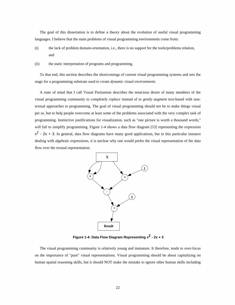
The goal of this dissertation is to define a theory about the evolution of useful visual programming
languages. I believe that the main problems of visual programming environments come from:
(i) the lack of problem domain-orientation, i.e., there is no support for the tools/problems relation,
and
(ii) the static interpretation of programs and programming.
To that end, this section describes the shortcomings of current visual programming systems and sets the
stage for a programming substrate used to create dynamic visual environments.
A state of mind that I call Visual Puritanism describes the tenacious desire of many members of the
visual programming community to completely replace instead of to gently augment text-based with non-
textual approaches to programming. The goal of visual programming should not be to make things visual
per se, but to help people overcome at least some of the problems associated with the very complex task of
programming. Instinctive justifications for visualization, such as "one picture is worth a thousand words,"
will fail to simplify programming. Figure 1-4 shows a data flow diagram [53] representing the expression
x2 - 2x + 3. In general, data flow diagrams have many good applications, but in this particular instance
dealing with algebraic expressions, it is unclear why one would prefer the visual representation of the data
flow over the textual representation.
X
* *
2
-
+
3
Result
Figure 1-4: Data Flow Diagram Representing x2 - 2x + 3
The visual programming community is relatively young and immature. It therefore, tends to over-focus
on the importance of "pure" visual representations. Visual programming should be about capitalizing on
human spatial reasoning skills, but it should NOT make the mistake to ignore other human skills including
22

the ability to deal with abstract entities such as text. Hence, a good (visual) programming environment
should carefully combine both skills.
Empirical tests suggest that despite their versatility, general-purpose visual programming systems have
limited usefulness. Green has compared the performance of programmers using textual and non-textual
representations [48]. Surprisingly, he found that in many cases the programmers using textual
representations outperformed the those using non-textual representations. Brooks [11], being even more
skeptical, concluded that visual programming is temporary hype leading into a blind alley:
“A favorite subject for Ph.D. dissertations in software engineering is graphical, or visual, programming - the
application of computer graphics to software design. Sometimes the promise held out by such an approach is
postulated by analogy with VLSI chip design, in which computer graphics plays so fruitful a role. Sometimes
the theorist justifies the approach by considering flowcharts as the ideal program-design medium and by
providing powerful facilities for constructing them.
Nothing even convincing, much less exciting, has yet emerged from such efforts. I am persuaded that nothing
will.”
Before we can find a way out of this alley we need to understand some of the main claims and problems
of visual programming.
Visual Languages Lack Domain-Orientation
With very few exceptions visual programming languages are of a very general purpose nature. In other
words, they lack problem domain-orientation. These general-purpose visual programming systems that
visually represent concepts found in conventional programming languages such as boxes and arrows
actually represent procedures and procedure calls. These systems have two advantages. First, they are
applicable to a wide range of domains. Second, visual representations can facilitate syntactic constructions.
For instance, shapes in BLOX Pascal (Figure 1-5) guide the programmer toward making syntactically
correct constructions [39]. However, general-purpose visual programming systems are difficult to use for
novice programmers (e.g., BLOX Pascal still requires basic Pascal knowledge) and provides little - if any -
gratification to expert programmers.
IFWHILE BLOCK
BLOCKDO
BLOCK
THENBLOCK
IFELSE
BLOCK
Figure 1-5: BLOX Pascal
23
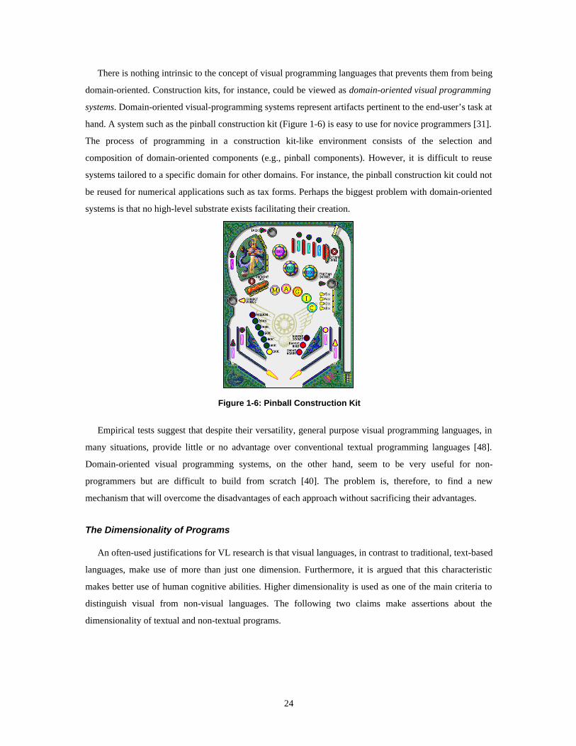
There is nothing intrinsic to the concept of visual programming languages that prevents them from being
domain-oriented. Construction kits, for instance, could be viewed as domain-oriented visual programming
systems. Domain-oriented visual-programming systems represent artifacts pertinent to the end-user’s task at
hand. A system such as the pinball construction kit (Figure 1-6) is easy to use for novice programmers [31].
The process of programming in a construction kit-like environment consists of the selection and
composition of domain-oriented components (e.g., pinball components). However, it is difficult to reuse
systems tailored to a specific domain for other domains. For instance, the pinball construction kit could not
be reused for numerical applications such as tax forms. Perhaps the biggest problem with domain-oriented
systems is that no high-level substrate exists facilitating their creation.
Figure 1-6: Pinball Construction Kit
Empirical tests suggest that despite their versatility, general purpose visual programming languages, in
many situations, provide little or no advantage over conventional textual programming languages [48].
Domain-oriented visual programming systems, on the other hand, seem to be very useful for non-
programmers but are difficult to build from scratch [40]. The problem is, therefore, to find a new
mechanism that will overcome the disadvantages of each approach without sacrificing their advantages.
The Dimensionality of Programs
An often-used justifications for VL research is that visual languages, in contrast to traditional, text-based
languages, make use of more than just one dimension. Furthermore, it is argued that this characteristic
makes better use of human cognitive abilities. Higher dimensionality is used as one of the main criteria to
distinguish visual from non-visual languages. The following two claims make assertions about the
dimensionality of textual and non-textual programs.
24
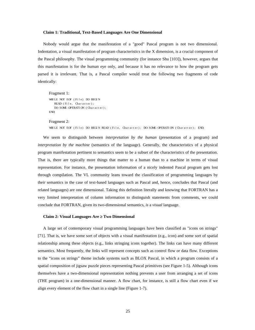
Claim 1: Traditional, Text-Based Languages Are One Dimensional
Nobody would argue that the manifestation of a "good" Pascal program is not two dimensional.
Indentation, a visual manifestation of program characteristics in the X dimension, is a crucial component of
the Pascal philosophy. The visual programming community (for instance Shu [103]), however, argues that
this manifestation is for the human eye only, and because it has no relevance to how the program gets
parsed it is irrelevant. That is, a Pascal compiler would treat the following two fragments of code
identically:
Fragment 1:
WHILE NOT EOF (File) DO BEGIN READ (File, Character); DO-SOME-OPERATION (Character);END;
Fragment 2:
WHILE NOT EOF (File) DO BEGIN READ (File, Character); DO-SOME-OPERATION (Character); END;
We seem to distinguish between interpretation by the human (presentation of a program) and
interpretation by the machine (semantics of the language). Generally, the characteristics of a physical
program manifestation pertinent to semantics seem to be a subset of the characteristics of the presentation.
That is, there are typically more things that matter to a human than to a machine in terms of visual
representation. For instance, the presentation information of a nicely indented Pascal program gets lost
through compilation. The VL community leans toward the classification of programming languages by
their semantics in the case of text-based languages such as Pascal and, hence, concludes that Pascal (and
related languages) are one dimensional. Taking this definition literally and knowing that FORTRAN has a
very limited interpretation of column information to distinguish statements from comments, we could
conclude that FORTRAN, given its two-dimensional semantics, is a visual language.
Claim 2: Visual Languages Are ≥ Two Dimensional
A large set of contemporary visual programming languages have been classified as "icons on strings"
[71]. That is, we have some sort of objects with a visual manifestation (e.g., icon) and some sort of spatial
relationship among these objects (e.g., links stringing icons together). The links can have many different
semantics. Most frequently, the links will represent concepts such as control flow or data flow. Exceptions
to the “icons on strings” theme include systems such as BLOX Pascal, in which a program consists of a
spatial composition of jigsaw puzzle pieces representing Pascal primitives (see Figure 1-5). Although icons
themselves have a two-dimensional representation nothing prevents a user from arranging a set of icons
(THE program) in a one-dimensional manner. A flow chart, for instance, is still a flow chart even if we
align every element of the flow chart in a single line (Figure 1-7).
25

c
a
b ca b=?
Chart 1 (neat) Chart 2 (linear)
Figure 1-7: Isomorphic Flow Charts: Neat and Linear
So, again, the second dimension is interpreted only by the human and not the machine. In other words,
the dimensionality of this type of visual language is about the same as the dimensionality of text-based
languages. Therefore, if we use dimensionality as a criterion for “visuality” we would be forced to conclude
that a flow chart is about as “visual” as a Pascal program.
The point is not to assert that Pascal is a visual programming language but the question arises whether
we can come up with a more meaningful criterion for “visuality” than dimensionality. Additionally, I like
to point out that the discrepancy between human and machine interpretation of current diagrammatic
representation could be one of the main causes of the low visual language acceptance. One of the reasons
why so many people dislike visual languages is because they think VLs make bad use of screen estate [11],
i.e., visual programs "are too big." Maybe we need to increase the number of spatial characteristics
pertinent to machine interpretation by including so far unused characteristics crucial to human
interpretation. For instance, in Figure 1-8 chart 1 seems to be much tidier than chart 2, probably because it
makes better use of implicit spatial relations such as writing order (in the US: left to right, top to bottom).
ab
cc
a
b =?
Chart 1 (neat) Chart 3 (messy)
Figure 1-8: Neat and Messy Charts
26

Petre et al. [89] call the use of layout and perceptual clues, which are not formally part of a notation
describing the semantics of a visual language, “secondary notation.” Spatial relationships, including
adjacency, clustering, white space, and labeling, are employed to clarify information such as structures,
functions, and relationships in diagrammatic representations. Furthermore, they argue that the secondary
notation is crucial to comprehensibility:
“Poor use of secondary notation is one of the things that typically distinguishes a novice’s representation from
an expert’s.”
As long as visual languages give the user so much freedom that the icons, representing primitives in the
visual program, can be completely rearranged to a total, nonsensical mess without changing the semantics
of the program, I do not think we have found “truly” two-dimensional programming languages.
Visual Programming Is Natural Because People like to Doodle
One claim of visual programming is that it is “natural” because people, including traditional
programmers, often create diagrammatic representations to solve problems. I myself doodle a lot to
program: class hierarchies, data structures, state diagrams, etc. All these things appear to be intrinsically
spatial to me. These diagrams help me to understand certain issues of programming problems or they help
me to communicate problems to peers. However, what is the nature of these diagrams in terms of their life
span, completeness, consistency , and complexity?
• Life span: Although at the time of solving a problem (often just a very small fraction of a big
programming project) doodling a diagram may be crucial, the diagram is often disposed of after the
problem is solved. In other words, the life span of these diagrams is often very short, from a couple of
minutes to a couple of days.
• Completeness: The diagram is typically only related to a very small fragment of the entire project (e.g.,
a diagram of a data structure). Even these fragments are complete only to the point where they fulfill
their purpose of explaining an abstract relationship to another person.
• Consistency: In the process of sketching a diagram, understanding often progresses or even changes
radically over time and so does the notation used. That is, not only does the diagram evolve over time
but also the notation capturing the semantics of the diagram. This can lead to inconsistencies in the
diagram. Due to the short life span of a diagram this usually does not have bad implications.
• Complexity: Diagrams are less useful if they become to complex. The advantage of using diagrams
arises from human perceptual abilities such as recognizing interesting patterns and structures in images.
But no matter what spatial notation we use there always will be a critical mass of complexity at which a
visual representation becomes overwhelming and therefore loses its "intuitive" appeal. This, of course,
27
does not mean that there cannot be a mechanisms to break up complexity, but so far I have not seen a
convincing one.
No doubt, the use of diagrams to solve problems can be crucial. However, we have to be careful with
simplistic conclusions such as: “to doodle is natural” therefore “visual programming is natural.”
The problems solved by doodling on the back of some envelope are different in nature from the
problems arising in big programming projects. This does not mean that there cannot be any useful visual
programming environment. However, we have to be aware that the nature of a small problem may be very
different from the nature of a more complex problem.
Explicit Versus Implicit Spatial Notations
One problem of visual programming is that it makes extensive use of screen estate [11]. Partial solutions
include the use of larger screens or mechanisms to zoom in and out of spatial representations. However, I
believe that the main problem arises from the use of explicit spatial notations that are due to the general-
purpose nature of most visual programming languages. Implicit spatial notations, although less flexible than
explicit spatial notations, can be used in domain-oriented applications to substantially increase the spatial
density of visual representations.
Explicit as well as implicit spatial notations are concerned with the visual representation of relations
between objects in diagrams. I distinguish two types of objects: The core objects, such as programming
primitives in visual programming languages, are the objects pertinent to a user. Unlike implicit notations,
explicit notations include relation objects, such as labeled arrows, in addition to the core objects.
The use of relation objects in explicit spatial notations makes a representation very flexible. The relation
between the two core objects in Figure 1-9 indicated by the arrow relation object could have very different
semantics such as father, super class, boss, etc.
28

core objects (agents)
relation object(links between agents)
Figure 1-9: Explicit Spatial Notation
Flexibility arises from the existence of a relation object that can be augmented in unlimited ways. An
arrow, for instance, can have many different characteristics including labels, color, hatch pattern, arrow
type, and thickness. This flexibility can be employed by users to create new relation types. On the other
hand, the explicit notations are wasteful with respect to spatial attributes of core objects. The position, for
instance, in Figure 1-9 of the two core objects is completely irrelevant. What matters is the orientation of
the relation object with respect to the core objects. Consequently, the semantics of a diagram using explicit
spatial notations is not related to the Gestalt of the core objects. In other words, we could rearrange the core
objects to any visually pleasant or unpleasant diagram without changing the semantics of the diagrams (see
Figure 1-9).
The combination of wasting spatial attributes of core objects and the use of relation objects can lead to
low spatial densities of explicit spatial notations. In visualization tools, such as object class graphers, the
space used by relation objects as well as their number can easily exceed space and number of core objects.
At the cost of flexibility, implicit spatial notations can increase the spatial density of representations by
(i) avoiding the use of relation objects, and (ii) making more economical use of spatial attributes of core
objects. In implicit spatial notations semantics is derived from spatial relations between core objects. These
spatial relations, in turn, directly emerge from the positions of core objects. Spatial relations can be
topological, (proximity, order, enclosure, continuity) and Euclidean (angularity, parallelism, and distance)
[51].
29

Implicit spatial notations are less flexible because they rely on the more subtle perception of implicit
spatial relations. Since these spatial relations are implicit, that is they have no physical manifestation in a
diagram, they cannot have characteristics such as labels, colors, hatch patterns, arrow types, or thicknesses.
It can be difficult to discern a large number of different spatial relations. Most visual programming
paradigms based on implicit spatial notations employ only a very small number of spatial relations.
ChemTrains [4-6], for instance, uses only one (enclosure).
The use of implicit spatial notation can lead to very efficient and natural representations if there is an
intuitive mapping between the semantics to be represented and the spatial relation selected. In Figure 1-10
the relation between two core objects, a roof and a frame of a house, is captured implicitly; the roof is
above the frame.
Figure 1-10: Implicit Spatial Notation: Roof is Above Frame of House
In this case, the spatial orientation of how we perceive real roofs and real houses through our bodies in
the three-dimensional world quite naturally maps to the two-dimensional figure above of a house with a
roof. In this case it seems absurd to introduce any relation objects such as the arrows in Figure 1-11.
aboveabove
Figure 1-11: Explicit Spatial Notation: Roofs and Frames of Houses
Especially the diagram in Figure 1-11 on the right-hand side not only seems to be overly explicit, it even
seems to be misleading. On the one hand, the relation object (the arrow) indicates that the roof is above the
frame. On the other hand, secondary notation [89], in this case the relative position of the roof and the
frame, suggests that the roof is below the frame. The roof, the frame, and the relation between them are not
abstract. We are misled by the mismatch between our understanding of physical reality and spatial notation.
This is not to say that implicit spatial notations are intrinsically superior to explicit spatial notations.
However, it suggests that:
30

the implicit spatial notation should be preferred over the explicit spatial notation if we are familiar
with the objects and relations of a representation either from our physical experience or from our
understanding of the world in terms of spatial metaphors such as orientation [64].
The majority of visual programming languages are of a general-purpose nature. Consequently, they
patronize the use of explicit spatial notations. More specifically, most of the visual programming languages
belong to the class of “icons on strings” environments [71], where the “icons” are the core objects and the
“strings” the relation objects. The migration from general-purpose languages toward more task or domain-
oriented languages would not only reduce the transformational distance between the problems to be solved
by computer users, but it would increase the spatial density of visual programs by enabling the visual
language designer to move from explicit spatial notations to implicit spatial notations.
A good example of a highly dense representation entailing an implicit spatial notation is the game of
chess. The relationships between the chess pieces are very complex due to the large number of pieces that
can participate in many relationships simultaneously. It would be simply overwhelming to have an explicit
spatial notation such as arrows between pieces denoting all possible relationships.
The use of implicit spatial notation is so natural that we often are not even aware of the presence of a
notation at all. The way we create drawing on a white board or indeed the way we write relies on implicit
spatial notation. This has only very little to do with our direct physical experience. For instance, the
characters of our alphabet are artifacts of our culture and not natural entities. The way we write words by
stringing together individual characters horizontally from left to right (Western civilization) adheres to a
very powerful implicit spatial notation. Although we have no problem reading the following sentence:
we gain very little from the flexibility of explicit spatial notations. Because we do not usually think
about spatial notation in this kind of domain, the transformation from implicit to explicit spatial notation
will sound somewhat complex. The semantics of words - a word is a sequence of succeeding characters -
can be mapped from the currently implicit spatial notation - the character Y immediately right to the
character X is the successor of X - to an explicit spatial notation - an arrow connects a character with its
successor. As a result of this notational shift, we gained the ability to move the individual characters
arbitraring without changing the sentence. However, it becomes immediately apparent that by giving up the
Gestalt principles (a word is a horizontal string of characters) we have also lost the ability to read the
sentence efficiently:
31

What are the implications of explicit and implicit spatial notations to the relationship of people,
problems, and tools? Explicit spatial notations are best for tools that are not specific for some problem nor
specific to some kind of person using it. Implicit spatial notations, on the other hand, are best suited for
more problem domain-oriented applications. The implicit spatial notations are often based on either
physical experience or metaphorical understanding of space. The latter may depend on the culture in which
the notation was shaped. In the Arabic, Japanese, and Chinese cultures, the implicit spatial notations are
different.
1.3.6. Object-Oriented Programming
The paradigm of object-oriented programming (OOP) has unified the formerly isolated entities
representing state and behavior into a single concept called the object. Another major contribution is the
support of incremental definition of state and behavior by means of inheritance at the level of programming
languages. The mapping of physical entities such as buttons and windows onto the computational concept
of objects seems to be more “natural” than the creation of data structures and procedures. With respect to
the people, tools, and problems relationship, OOP appears to be ideal because it reduces the
transformational distance between the problem and the tool.
People
Object-OrientedTools
Problems
"natural"mapping
reduced transformation
distance
Also, OOP as a tool claims to be more natural, but this claim regarding the “naturalness” is still debated.
Despite this claim the creation of good, object-oriented code is less than trivial. The question is one of
whether natural concepts are not appealing to the C programming community or if the object-oriented
approach is not so natural after all.
How can useful dynamic visual environments be created with OOP? Many OOP environments come
with libraries of simple graphical objects such as rectangles and buttons. However, these environment do
not have an intrinsic spatial notation (implicit or explicit).
32

1.3.7. Spreadsheets
Spreadsheets support the definition of implicit spatial notations. The spatial structure of a grid can be
used to represent task-specific relations. Nardi argues that spreadsheets support the incremental
development of external, physical models of the problem to be solved [24]. According to her, typical
spreadsheet users do not map a mental model of a solution for a problem onto the spreadsheet. Instead, the
spreadsheet is an evolving artifact. As the artifact evolves so does the understanding of the problem and its
solution.
People
Tools Problems
flexible, implicit spatial
notation
incremental problem model
development
Spreadsheets are task-specific but not domain-oriented. The formula language featured by spreadsheets
furnishes task-specific primitives [84] such as taking averages, rounding numbers, and operating on dates.
However, the notion of cells and formulas is neither domain-oriented nor domain-orientable. Cells may
contain domain-oriented data or formulas; however, this domain-orientation is implicit. That is, cells may
contain fragments of domain-oriented information but the models are only in the heads of the users. For
instance, a cell B1 containing the formula =A1*3.14*2 could be perceived as a cell computing the
circumference of a circle based on its radius stored in cell A1. We can make this induction based on the
interpretation that the value 3.14 is an approximation of the constant π and, furthermore, recognizing the
“radius of circle to circumference” formula. Of course, this induction may be completely wrong. For
instance, the value 3.14 may not be intended to approximate π and, hence, the formula may have been
utterly unrelated to the domain of circles and geometric relationships. Consequentially, the direct relation
between a spreadsheet as a tool and the problem to be solved is very weak. Nonetheless, the intuitive nature
of the relation between the tools and people and between people and problems has led to the big success of
spreadsheets in enabling end users to create solutions to their problems.
1.3.8. Spatial Metaphors
Metaphors have always played an important role in the understanding of the rather abstract concept of a
computer. They have helped us to comprehend and to construct new concepts related to computers by
creating analogies to familiar concepts.
33

People
Tools Problems
analogiesto
familiarconcepts
Files, folders, procedures, and memory, to name just a few, visible or invisible, are all metaphors of
concepts with which we are already familiar. Spatial metaphors such as the desktop metaphor are enabling
an increasing number of people to use computers. However, metaphors also have their problems:
• Metaphors break down: The analogy between real-world situations and metaphors are limited in scope.
Resulting inconsistencies may be unavoidable, and they can confuse users.
• Metaphors are rigid: The spatial metaphors employed in current user interfaces are very rigid; that is,
they are not intended to be extended by application designers or users.
• Metaphors lack domain-orientation: Spatial metaphors focus on a generic user interface part of systems
and neglect the domain-specific functionality of applications.
• Metaphors are conservative: It is the very nature of a metaphor to relate the present to the past.
Considering this, we must realize that metaphors lack the element of progress, and hence might engage
designers too much in emulating past technology instead of creating completely new media.
Metaphors Break Down
Spatial metaphors support the transfer of skills by implying likeness or analogies to real-world
situations. The transfer of skills can be positive by suggesting helpful operations to users; however, it can
also be negative by implying limitations, for example, due to the physical nature of the real-world situation.
For instance, the paper and pencil metaphor employed in pen-based user interfaces, on the one hand, is very
powerful in re-using skills acquired by the use of physical papers and pencils. On the other hand, though,
physical papers and pencils are very limited in their functionality. Moving fragments of a drawing on real
paper from one location to another is a non-trivial task. At the expense of consistency a spatial metaphor
may choose, and in many cases will choose, to extend or modify the meaning of the vocabulary of
operations suggested by the real-world situation with a certain degree of physics-free magic. Interface
designers have to be aware of resulting inconsistencies. Designers need to make trade-offs between the
potential for confusion due to inconsistency and the value added by extending the metaphor.
Rigidity: How Can Users Extend Metaphors?
Spatial metaphors appear to be very rigid with respect to their extensibility by end users or application
designers. Macintosh users, for instance, may change certain parameters of their desktop such as the color
34

and pattern, or they can change the position of objects such as files and folders by dragging them; however,
there is no easy way to include new behaviors. A study by Apple showed that people attempt to deal with
the flow of information in their real-world workspaces by creating piles of documents. A team of Apple
researchers tried to reflect this activity by extending the Macintosh desktop metaphor with a “pile”
metaphor [72]. Their work indicated that adding this metaphor required a significant amount of knowledge
and effort that would be way beyond the scope of an end-user or even an application designer. The question
remains whether spatial metaphors are intrinsically difficult to extend or if only the implementations of
spatial metaphors are difficult to extend.
Metaphors Lack Domain-Orientation
From the viewpoint of the HCI community, it seems to be desirable to completely separate the user
interface and the application [88]. In terms of user interfaces, the universe of computer applications seems
to be reducible to a set of interface objects such as buttons, windows, and menus. In this scheme the
application independent spatial metaphor serves as an access mechanism to application specific
functionality. We (the human-interface experts) believe that we have successfully reduced the complexity
of creating computer systems by separating the interface from the application. Yet, if we look at real-world
artifacts, such as cars, we note that most of the critical interfaces are very application-specific. For instance,
a steering wheel makes perfect sense to control the direction of the car; however, it would be of little use
attached to a coffee machine. The strong separation of spatial interface metaphor and application might be
good from an interface designer’s point of view, but this does not necessarily imply that it also would serve
users well. After all, who would like to steer a car by double-clicking some buttons?
Metaphors Are Conservative
Metaphors can be the source of conservative forces complicating the introduction of radically new
concepts that cannot be explained as simple analogies of familiar concepts.
1.3.9. Summary: The Diversity of People and Problems Requires Substrates to BuildDomain-Oriented Tools
The list of presented solution approaches (Table 1-1) is by no means as exclusive as has been presented.
On the contrary, the concepts entailed in the different approaches are highly overlapping. Despite that large
overlap, however, the individual user communities are largely disjoint. The challenge is to cross community
borders and to reasonably combine the advantages of these approaches into a new paradigm, avoiding their
disadvantages and introducing new concepts if necessary.
35

Table 1-1: Past Approaches
Approach Pros ConsHigh-Level ProgrammingLanguages
People
Tools Problems
improved syntax
• computer architectureindependent means ofprogramming
• too generic; largetransformation distance to mapa problem onto general-purposeconstructs
Task-Specific LanguagesPeople
Tools Problemstask/problem domain-orientation
• support tasks by providinghigh-level primitives tailoredtoward tasks
• do not transfer easily to non-intended tasks
Visual ProgrammingPeople
Visual Tools Problems
capitallizing on visual perception and
reasoning
• capitalizes on human spatialcapabilities
• reduces syntactic problems
• lacks domain-orientation
• static interpretation ofprograms and programming
• spatial notations are “hardwired”
• does not scale well
Object-Oriented ProgrammingPeople
Object-OrientedTools
Problems
"natural"mapping
reduced transformation
distance
• the notion of objects withbehavior is more intuitive thandata structures and procedures
• incremental definition ofbehavior and state
• no intrinsic spatial notation
• no intrinsic human-computerinteraction scheme
SpreadsheetsPeople
Tools Problems
flexible, implicit spatial
notation
incremental problem model
development
• support the definition ofimplicit spatial notations
• incremental problem solvingand problem understandingthrough physical model
• task-specific
• mapping between problem andspatial notation of tool isimplicit in formulas
• no support for domain-orientation: users cannot extendspreadsheet model withproblem domain-orientedsemantics
Spatial MetaphorsPeople
Tools Problems
analogiesto
familiarconcepts
• help to comprehend newconcepts by creating analogiesto familiar concepts
• break down
• are rigid
• lack domain-orientation
• are conservative
36

1.4. Proposed Approach: Theoretical Framework
This section introduces the theoretical framework of this dissertation and discusses the four major
contributions. The previous sections have illustrated how different programming approaches have
addressed the relationships among people, tools, and problems. None of the approaches completely covered
all three relations. Could there be programming approaches that provide complete coverage, and if so, what
kind of advantages and disadvantages would they have? Throughout the rest of this document, discussions
are organized with respect to the four major contributions of this dissertation aimed at the three relations:
• Construction Paradigm: A programming substrate should include a versatile construction paradigm to
build dynamic, visual tools for a wide range of problem domains.
• Programming as Problem Solving : A construction paradigm should be problem solving oriented rather
than domain-oriented. It should support the exploratory nature of problem solving by providing
mechanisms to incrementally create and change spatial and temporal representations that are tailored
toward problem domains.
• Participatory Theater: A construction paradigm should include human-computer interaction schemes,
giving people appropriate control over tools. Participatory theater combines the advantages of human
computer interaction schemes based on direct manipulation and delegation into a continuous spectrum
of control and effort.
• Metaphors as Mediators: Metaphors are used as problem representations helping people to
conceptualize problems in terms of notions they can relate to. Construction paradigms should be able to
evoke metaphors by including mechanisms to deal with space, time, and interaction.
1.4.1. Construction Paradigms
A construction paradigm should be like an application framework [60, 91] in that it should provide
mechanisms to define and specialize functionality, and to create user interfaces. Moreover, it should
provide paradigms useful to conceptualize a wide variety of problems.
The kind of programming substrates that I am interested in should provide a versatile construction
paradigm to build dynamic, visual tools for problem domains such as:
• Artificial Life Environments [59]
• Visual Programming Languages [12, 26, 41, 45, 58, 62, 79, 106]
• Programmable Drawing Tools [23]
• Simulation Environments [24, 107, 113, 117]
37

• Games [54]
• Complex Cellular Automata [112]
• Spreadsheet Extensions [33, 55, 68, 81, 84, 90, 108]
All these domains have the following characteristics in common:
• They are visual: Certain pertinent aspects of applications in these domains have non-textual, visual
manifestations.
• They employ spatial notations: The visual manifestations can be formally interpreted through implicit
or explicit spatial notations. For instance, in a board game such as chess, objects represent game pieces
and the relationships among the pieces given by the implicit spatial notation of the game representation
define the state of the game.
• They are dynamic: Artificial life forms, patterns of cellular automata [112], units of a simulation, etc.,
change state over time. For instance, they may change position, look, or internal properties.
• They include human-computer interaction schemes: Many applications include direct manipulation
[57, 102] to create and modify artifacts. For instance, in the case of visual programming languages, a
user programs by drawing a diagram representing a program using direct manipulation. Additionally,
applications such as artificial life environments require a more proactive scheme in which entities have a
more autonomous behavior that is not manipulated directly by a user.
• They support “what-if” games: In order to support “what if” games, it is necessary to have a responsive
environment. Furthermore, the environment should support incremental changes of behavior and of the
look of entities.
The main point of a construction paradigm is to acknowledge the perception of programming as
problem solving , to include human-computer interaction schemes supporting participatory theater , and to
utilize metaphors as mediators by furnishing functionality that can evoke metaphors.
1.4.2. Programming as Problem Solving
I endorse the view of programming environments as problem-solving vehicles supporting the
incremental creation and modification of spatial and temporal representations. The more traditional view of
programming environments as implementation facilitating devices assumes that a problem is sufficiently
well understood that the process of programming is a mapping of the this problem understanding onto a
programming mechanism [47]. However, adopting the “programming as problem solving” view leads to a
programming substrate of a different nature, facilitating the problem-solving process rather than
“implementation as mapping” processes as they are advocated, for example, by Dijkstra [18].
38

The programming as problem solving view is suited for situations that require problem framing. Schön
notes that professional design practice has as much to do with understanding the problem as with solving
the problem [100]. In large projects programming as problem solving may only be used in an early brain
storming phase to find a suitable representation that later guides more traditional software engineering
approaches, such as cleanroom software engineering [75].
A programming environment that facilitates problem solving should support change in representation.
Simon points out that suitable representations are crucial for the solution of a problem [105]. The process of
problem solving includes changing representations until the solution becomes transparent. Studies show the
important role visually inspectable models play in problem-solving processes [84]. Problem-solving
proceeds by creating external representations [67] of the solution, in addition to internal representations
stored in the brain, visually inspecting this solution, noticing problematic aspects, and repairing the
problematic areas by altering the proposed solution. A substrate for visual environments should, therefore,
enable users to create and explore different spatial representations rather than force them to adapt to one
built-in representation.
Spreadsheets are powerful vehicles to deal with ill-structured and incomplete problems. Tables are
visual formalisms [83, 84] of spreadsheets, facilitating the “on the fly” creation of implicit spatial notation.
Spreadsheets are good tools for problem solving because the implicit spatial notation of cells in a grid can
be adapted by users to organize information in many different ways. The meaning of the spatial notation is
only in the mind of the user and does not need to be committed formally to the tool.
Acknowledging the exploratory nature of problem solving, a substrate should support an evolutionary
style of change of representation by featuring a flexible spatial notation mechanism. This mechanism
should have the ability to grow throughout the process of problem solving, incrementally reflecting the
evolution of problem understanding. Implicit spatial notations are very flexible because they rely to a large
degree on interpretation by an observer. The observer can quickly change the interpretation and, once
satisfied, commit the relations (in the case of a spreadsheet, by adding formulas).
Green reaches a similar conclusion by viewing the process of programming as opportunistic planning in
design[46]. He stresses the pertinence of the modifiability of notations. Consequently, a substrate that
supports the creation of domain-oriented environments must include mechanisms to support the
modifiability of notations. Furthermore, the construction paradigm underlying the substrate should avoid
the need for premature commitment to design decisions. That is, the construction paradigm should not have
to rely on any “proper” sequence of operations resulting from design strategies, such as top down.
Visual environments can support dynamic representations. Funt [36] pointed out the importance of
diagrams in problem-solving. His system, WHISPER, deals with the simulation of complex objects in
39

motion. The system can detect collisions and other motion discontinuities. Later, Gardin [38] applied a
slightly different approach by using a “molecular” decomposition of behaving units.
People, Tools, and Problems Revisited: The Domain-Orientation Paradox
Would the ideal tool support all three relations of the people, tools, and problems triangle (Figure 1-12)?
What would be the nature of a highly usable, problem domain-oriented tool supporting problem solving?
This leads to the domain-orientation paradox.
People
Tools Problemsproblem domain-oriented
ortailorable toward domain
easy to understandeasy to use
facilitateproblem solving
Figure 1-12: The “ideal” tool?
Domain-Orientation Paradox of Problem-Solving Tools:
If a tool is considered a problem-solving tool having an exploratory character that supports not only
solving a problem but, more importantly, finding it first (or as part of the problem-solving process), then
how can the tool be problem domain-oriented?
Problem solving and domain-orientation can be two combatant forces embellishing the design of
construction paradigms. Problem solving, on the one hand, requires flexible, general purpose mechanisms
to explore the space of representations supporting the problem framing aspect of design [100]. Domain-
orientation, on the other hand, empowers users by reducing the transformation distance between problem
and tool [29]. An ideal construction paradigm should support the exploratory nature of problem solving,
and, at the same time, be orientable toward problem domains.
Layered Architectures
One approach to deal with the domain-orientation paradox of problem-solving tools is by using a
layered architecture (Figure 1-13). A problem solving-oriented construction paradigm layer supports the
creation of domain-oriented dynamic visual environments.
40

Domain-OrientedApplications
Problem Solving-Oriented Construction Paradigm
General-PurposeProgramming Language
Figure 1-13: Generic Layered Architecture for Domain-Oriented Environments
Related approaches propose the use of intermediate layers between applications and programming
languages to reduce the cost of design: Nardi [60, 83, 84] suggest the use of visual formalisms to bridge the
gap between general programming languages and task-specific applications. Fischer [31] postulates
construction kits as mechanisms to create domain-oriented artifacts. Glinert [40] points out the need for
visual metatools to create domain-oriented visual programming languages.
A versatile construction paradigm should not be oriented toward domains other than the domain of
problem solving. The construction paradigm should be a generalization of visual formalisms, construction
kits, and visual metatools. That is, the same construction paradigm should be capable of creating a wide
range of visual environments such as spreadsheets, construction kits, and visual programming languages.
Intrinsic User Interfaces: From Human-Widget Communication to Human Problem-DomainCommunication
A programming substrate that supports problem solving should have an intrinsic user interface.
Traditionally, the task of creating an application is divided into the creation of abstract application
functionality and the design of a user interface. User Interface Management Systems (UIMSs) are metatools
endorsed by the human-computer interaction community to create user interfaces [34, 88]. UIMSs are
shallow in the sense that they have only a very limited linkage to the application. A UIMS controls the
layout of user interface widgets such as buttons, scrollers, and menus. These widgets, in turn, are linked by
the UIMS user to application code. The semantics of the coupling between the widget level and the
application level is limited to concepts such as changing the value of some variable or calling some
procedure. Consequently, the maintenance of the user interface as a result of a change of the application can
be very labor intensive. Functions added to the application need to be linked explicitly to some dialog box
in the form of some widget by the user interface designer. Hence, human-computer interface metatools,
such as UIMSs, mostly enable the design of human-widget interfaces (Figure 1-14) instead of supporting
human-problem domain interaction [28]
41

Human Widget Application
Figure 1-14: Human-Widget Interaction
UIMSs provide little support for artifact interfaces. Dialog boxes designed with UIMSs are only of
secondary interest to a user in the sense that they do not represent the artifact to be created with a tool such
as a word processor. In a word processor the artifact is the document and not dialog boxes used to operate
on the document. The human-computer interaction of an artifact interface is often very complex and cannot
be reduced to simple standardized widgets such as buttons. In a word processor, for instance, interactions
include selecting objects, dragging objects, rearranging layout, editing pictures, etc. Hence, what we need is
a mechanism to increase the coupling between the application and its user interface and we also need tools
to design artifact interfaces. Ideally, a tool would include a construction paradigm with an intrinsic user
interface [69].
1.4.3. Participatory Theater: The Art of Knowing When to Invoke Programs
A construction paradigm should include human-computer interaction schemes giving people appropriate
control over tools. Participatory theater combines the advantages of human computer interaction schemes
based on direction manipulation and delegation into a continuous spectrum of control and effort.
In addition to the problem of creating programs there is the problem of knowing how and when to
invoke them. By knowing how to program we have only solved part of the problem. What may seem
mundane at first, the invocation of programs, is at least as important as the creation of the program and I
will make the point that it can be just as challenging.
Human-computer interaction, from a technical point of view, can be understood as the art of invoking
the right program fragment at the right time in order to give users appropriate levels of control and effort.
First, I will use a theatrical metaphor to elaborate the conceptual issues of control and effort, introduced in
42

this chapter, regarding human-computer interaction, leading to a new interaction scheme called
participatory theater. Then I will discuss the technical implications for a substrate used to create domain-
oriented environments with varying needs for control and effort.
Concepts: From Direct-Manipulation to Participatory Theater
Traditional dynamic systems seem to fall into the two extreme end points of the continuous spectrum of
control and effort; direct manipulation [57, 102] and delegation[85]. On one end, users have maximal
control over the components of their system through direct manipulation. With respect to the theatrical
metaphor, direct manipulation interfaces are like hand puppets in the sense that users are completely in
charge of the play (Figure 1-15).
User
Figure 1-15: Direct Manipulation: Hand Puppets
However, direct manipulation can be too direct as a means of control for applications that model
autonomous entities such as the creatures of an artificial life world. Negroponte [85] suggests the theatrical
metaphor as an approach in which tasks are delegated to actors. This approach could be considered as the
opposite end of the control spectrum because once the scripts for actors have been created and the play has
started, the audience - the users - are left with no control over the play (Figure 1-16). The actors in the play
can do more sophisticated tasks than the hand puppets can. For instance, the activity of the actors is not
bounded by the inherent sequentiality of the single user in control.
43

User
Figure 1-16: Passive Audience
Traditional simulation environments are instances of the theatrical metaphor. The definition of
simulation attributes is similar to writing the script for an actor. After the simulation has been prepared and
once the simulation has been started the user of the simulation system becomes a passive observer watching
the progress of the simulation.
The point here is not to advocate one approach over the other. Instead, I suggest combining the virtues
of both approaches in the participatory theater metaphor(Figure 1-17) by perceiving control and effort as a
continuous spectrum rather than a discrete dichotomy of direct manipulation versus delegation. Adams and
diSessa [1] have observed that students were able to solve hard problem by “cheating.” They directly
manipulated microworlds that also functioned as a working part of a program.
Actors in the participatory theater will act according to their script unless the audience tells them to do
something different. Depending on the level of participation the interaction can assume any point in the
control and effort spectrum. If the users do not participate then they have no control over the play and
become passive observers with no effort involved. On the other hand, excessive participation will result in
the user taking over the play completely to the point of direct manipulation.
44

ok
User
dothis!!
Figure 1-17: Participatory Theater
To view control and effort as a spectrum ranging from full control (direct manipulation) to minimal
effort (delegation) relates back to the bread-baking story. The directness of action of baking bread from
scratch corresponds to direct manipulation [57, 102] where the tools used are of a largely passive character
in that they are operative only when in control by a user. On the other side of the spectrum is the “Buy the
Bread at the Store” approach, in which the bread-baking process is completely decoupled from user
activities. Furthermore, the person that actually bakes the bread did not receive explicit instructions by the
person in need of bread. In fact, the two people probably never met. General need for bread, not controlled
by any individual, caused implicit delegation.
The following section discusses the technical implications of the participatory theater metaphor to the
design of a substrate that facilitates problem solving through programming.
Technical Implications of the Participatory Theater Metaphor
A construction paradigm to build domain-oriented visual environments should support participatory
theater human-computer interaction schemes. That is it should support direct manipulation and delegation,
as well as combinations of direct manipulation and delegation.
To interact with a computer via a user interface means to invoke program fragments. We can think of
computers as tools embodying dormant behavior by storing a potentially large number of program
45

fragments. These fragments could have been created using the programming approaches discussed in
Chapter 1.
From a technical point of view, human-computer interaction can be viewed as the art of knowing how
and when to invoke programs. Human activities such a pressing a key on the keyboard or moving the
mouse activate dormant behavior of the computer by invoking the “right” program fragment. No matter
how potentially useful these program fragments are, they can be used only through appropriate invocation
mechanisms enabling users to interact with computers.
The construction paradigm has to include various reactive and proactive invocation mechanisms to
support a wide range of human-computer interaction. Nake [82] explains human-computer interaction in
terms of two coupled semiotic systems (Figure 1-18).
Input Device(e.g., mouse, keyboard)
Output Device(e.g., picture, sound)
Computer&
Programssigns signals
Figure 1-18: Semiotics of Interaction
In a reactive system, interaction is initiated by the user through a sign. The sign may manifest itself to
the computer through a signal triggered by the use of a keyboard or a mouse. The signal, in turn, will
activate dormant behavior that has been captured in the form of program fragments stored in the computer.
Executing the program fragment will take some time depending on the complexity of the fragment. The
execution will typically have side effects that manifest themselves to the user via output devices (screen,
sound, etc.).
This interaction scheme is reactive in the sense that the computer always reacts synchronously to signs
from the user. Depending on the time it takes to execute the program fragment activated by the sign and the
complexity of the fragment, we can distinguish among three interaction schemes:
• Batch Operation: The program to be executed is complex and it takes a long time to finish it (minutes,
hours, days). Because of the response time, batch operation is not considered interactive.
• Direct-Manipulation: The response time is very small (milliseconds, seconds) and the complexity of the
reaction is small. For instance, the action of selecting a rectangle on the screen and dragging it to some
other location is considered direct manipulation [57, 102]; the mapping from the mouse movement to
the movement of the rectangle is sufficiently simple to be perceived as direct manipulation. A typical
example of a program making use of this interaction scheme is a drawing program such as MacDraw.
46

• Programmable Direct-Manipulation: Programmable direct-manipulation goes beyond direct
manipulation by supporting the creation of new program fragments and linking them to a predefined
sign of interaction (e.g., a mouse click) by the user on the fly (while using the system). SchemePaint
[23] is an example of a so-called programmable application utilizing programmable direct-manipulation.
A consequence of reactive interaction schemes is that the computer is not doing anything unless told to
do so by the user. Proactive interaction schemes, on the other hand, can take the initiative and compute
without preceding activation by a user. In other words, in a proactive interaction scheme, user activity, in
terms of signs, and the invocation of program fragments are asynchronous.
The construction paradigm of Agentsheets consisting of autonomous agents supports proactive
interaction schemes. Agents can be viewed as metaphorical entities dealing with delegated tasks
asynchronously. In other words, the user or agent delegating a task does not have to wait for the completion
of the task but can continue doing other tasks.
Finally, reactive and proactive interaction schemes should not be considered exclusive approaches. The
challenge is to combine both schemes into one construction paradigm without causing confusion for users
of the substrate.
1.4.4. Metaphors as Mediators
Metaphors can be mediators between domain-oriented applications and problem solving-oriented
construction paradigms. On one hand, a large number of problem domains can share a small number of
metaphors by representing concepts from problem domains with metaphorical concepts such as flow. On
the other hand, the construction paradigm should support the implementation of these metaphorical
concepts.
Metaphors are used as problem representations helping people to conceptualize problems in terms of
notions they can relate to. Construction paradigms should be able to evoke metaphors by including
mechanisms to deal with space, time, and interaction.
47

CHAPTER 2DESIGN: AGENTSHEETS IS A CONSTRUCTION PARADIGM
Direct manipulation has its place, and in many regards ispart of the joys of life: sports, food, sex, and, for some,driving. But, wouldn’t you really prefer to run your homeand office life with a gaggle of well trained butlers, maids,secretaries... .
- Nicholas Negroponte
Overview
This chapter is about the design of Agentsheets, a domain-independent substrate for creating domain-
oriented, dynamic, visual environments. The design of Agentsheets - which supports the relationships
among people, tools, and problems - is discussed in the context of the four major contributions of this
dissertation. This chapter introduces the Agentsheets construction paradigm and its components; illustrates
how the construction paradigm supports the exploratory nature of problem solving; discusses the technical
implications of participatory theater for the design of Agentsheets; and describes how the notion of agents
organized in a grid can evoke metaphors of space and time. Then, the chapter enumerates four approaches
to define the behavior of agents; provides scenarios showing how to use Agentsheets; and compares
Agentsheets to related systems.
48

2.1. What is Agentsheets?
Agentsheets1 features a versatile construction paradigm to build dynamic, visual environments for a
wide range of problem domains such as art, artificial life, distributed artificial intelligence, education,
environmental design, object-oriented programming, simulation and visual programming. The construction
paradigm consists of a large number of autonomous, communicating agents organized in a grid, called the
agentsheet. Agents can use different communication modalities such as animation, sound and speech.
The construction paradigm supports the perception of programming as problem solving by incorporating
mechanisms to incrementally create and modify spatial and temporal representations. In a typical utilization
of Agentsheets, designers will define the look and behavior of agents specific to problem domains. The
behaviors of agents determine the meaning of spatial arrangements of agents (e.g., what does it mean when
two agents are adjacent to each other?) as well as the reaction of agents to user events (e.g., how does an
agent react if a user applies a tool to it?).
Users work with Agentsheets by placing agents into agentsheets and by interacting with agents. To
interact with a large number of autonomous entities, Agentsheets postulates participatory theater, a human-
computer interaction scheme combining the advantages of direct manipulation [57, 102] and delegation
[85] into a continuous spectrum of control and effort.
2.2. Construction Paradigm: Agents and Agentsheets
The Agentsheets construction paradigm facilitates the creation of dynamic, visual environment for a
wide range of domains. This section introduces the notions of agents and agentsheets, discusses the layered
architecture in terms of different people using different layers of tools based on Agentsheets, and describes
some design pragmatics arising from real use situations.
2.2.1. Basic Components: Agents and Agentsheets
The theoretical framework includes a layered architecture that supports the creation of domain-oriented
dynamic visual environments. To propose the mere existence of an intermediate layer between the domain-
oriented level and the general purpose programming level absorbing complexity is not sufficient. The
question is what is in that layer?
The requirements emerging from the intended domains to be supported (described in the theoretical
framework section) require a .i.construction paradigm ; that enables users to create new spatial notations.
1Agentsheets is the singular name of the system; it is capitalized and ends with an “s”
49

These notations consist of two types of entities: containers and content. The containers, called agentsheets,
contain agents. Containers include organizational principles such as tables, lists, and graphs organizing the
content. The following sections describe the components of this layer, which deals with containers and
content, called the spatio-temporal metaphor construction paradigm.
Content: Agents
The intended problem domains contain a potentially large number of communicating autonomous,
dynamic entities. These requirements have led to the notion of fine-grained agents serving as an active
computational media whose behavior is defined by the behavioral aggregation of individual agents. That is,
the agents employed in Agentsheets should be considered simple atoms of behavior that need to be
assembled into more interesting units of behavior, more like Minsky’s concept of agencies [77].
Agencies in Agentsheets are a collection of agents sharing a space and communicating with each other.
Agents are equipped with spatial communication mechanisms which allow them to interact with other
agents sharing the same space.
Agents are not just objects. Agents are objects in the sense that every agent class is a subclass of the
most generic class called “object” but, additionally, agents are equipped with spatial communication
mechanisms that allow them to interact with other agents sharing the same space. Furthermore, agents
support reactive interaction schemes such as direct manipulation [57, 102], proactive schemes such as
autonomous behavior, and reactive/proactive combinations such as tactile interfaces.
Agents are not just processes. The autonomous behavior of agents is related to the concept of processes
known from computer science in that both concepts deal with the illusion of parallelism on typically
sequential machines. Processes are relatively low level mechanisms featured in operating systems dealing
with concurrency. Agentsheets’ agents, on the other hand, are entities directly visible to users. Agents can
be viewed as active “objects to think with” [86] equipped with sensors and effectors to interact with users
or other agents.
Agents can be further reduced to subcomponents including:
• Sensors: Sensors invoke methods of the agent. They are triggered by the user (for example, clicking at
an agent) or by the Agentsheets process scheduler.
• Effectors: Effectors are mechanisms to communicate with other agents by sending messages to agents
either using grid coordinates or explicit links. The receiving agents may be in the same agentsheet, in a
different agentsheet on the same computer, or even in a different agentsheet on a different computer
(connected via a network). The messages, in turn, activate sensors of receiving agents.
50
• Behavior: The built-in agent classes provide a default behavior defining reactions to all sensors. In order
to refine this behavior incrementally, subclasses of agents can be defined making use of the object-
oriented paradigm [110].
• State: The state describes the agent’s condition.
• Depiction: Depiction is the graphical representation of the class and state; that is, the look of the agent.
Containers: Agentsheets
The workspace containing and managing agents is called the agentsheet. In its most complex form, an
agentsheet is a three-dimensional cube containing stacks of agents projected onto a two-dimensional
window. The content of an agentsheet can be manipulated like a canvas by applying tools to agents such as
tools to draw, erase, move, link, unlink, inspect, and activate agents.
An agentsheet is a structured container that not only contains agents but, additionally, includes forcing
functions to organize agents in space such that relationships between agents become transparent to users.
Grids are employed in Agentsheets to structure the space of agents because a grid makes implicit spatial
notations more transparent. In principal, agents could have any size, location and orientation in space to
maximize the flexibility of a spatial notation. The use of a grid reduces the number of possible diagrams
because it discretizes the positions of elements in the grid. At the same time, however, a grid increases
representational transparency by disambiguating implicit spatial relations between components.
51

Agents
Agent Structure
Depictions
Behavior(Methods)
Sensors Effectors
State
Figure 2-1: The Structure of an Agentsheet
The depiction in Figure 2-1 shows the graphical representation of an agentsheet as it is seen on the
screen by users. Each depiction represents the class of an agent; for example, the symbol of an electrical
switch denotes a switch agent. Furthermore, different states of an agent are mapped to different depictions;
for example, an open switch versus a closed switch.
Grids are a well-known spatial organization principle widely used in domains such as architecture.
Müller-Brockman [78] characterizes the purpose of grids as follows:
“The use of a grid system implies the will to systematize, to clarify; the will to penetrate to the essentials, toconcentrate; the will to cultivate objectivity instead of subjectivity;...”
The main reasons to use grids in Agentsheets are:
• Avoiding Brittleness: Without a grid, spatial relations can become very brittle. A brittle spatial
representation is a representation in which a small change to the visual manifestation of a program on
the screen by a user may result in a dramatically different interpretation by the machine. For instance,
moving an object (agent) on the screen one pixel may change its spatial relation to another object in an
underlying machine interpretation model from an adjacent relation to a non-adjacent relation. Grids
52

reduce brittleness by discretizing the positions of objects, and therefore they reduce the chance of
mismatches between the interpretation of a picture by a human and the machine.
• Relational Transparency: The use of grids increases the transparency of spatial relationships
considerably.
• Implicit Communication: Communication among agents is accomplished implicitly by placing them
into the grid. That is, no explicit communication channel between agents needs to be created by the user.
In the circuit Agentsheet shown in Figure 2-1, the electrical components get “wired-up” simply by
placing them in adjacent positions. The individual agents know how to propagate information (flow in
this case); for example, the voltage source agent will always propagate flow to the agent immediately
below it.
• Regularity: Grids also ease the location of such common regular substructures as one dimensional
vectors or submatrices.
An example of a brittle representation is the refrigerator case in the Janus kitchen design environment
[30]. A critiquing system built-in to Janus will alert the designer if a refrigerator is placed adjacent to a wall
with the refrigerator door facing the wall (Figure 2-2, A). Most designers would expect no implications
from moving the refrigerator one pixel to the left (Figure 2-2, B), yet the critiquing system would react
completely differently by no longer complaining about the bad design decision regarding the location and
orientation of the refrigerator. Situation B is still bad because the door of the refrigerator still cannot be
opened satisfactorily.
A B
Figure 2-2: Situation A and B of Refrigerator Facing a Wall
2.2.2. Agentsheets Users: Layers and Roles
Chapter 1 made the point that tools should be oriented toward the people using the tools and toward the
problem domains in which the tools are going to be used. But who are these people and what kinds of roles
do they play in interacting with the tool? On the one hand, the people that would like to use a tool often do
not have the experience or even the desire to create or modify the tool first. People who have the necessary
skills to create tools, on the other hand, frequently do not really need the tools they could create.
Agentsheets facilitates the design of tools with a layered architecture supporting different user roles with
different layers. The Agentsheets user interface includes different views of the tool for different user roles.
53

Four different roles have emerged during the past three years. (Different roles do not necessarily imply
different people). The roles are:
• End-User: Customizes scenarios by changing parameters of building blocks, adding and removing
building blocks. Plays “what-if” games by executing scenarios with different starting conditions.
• Scenario Designer: Composes a scenario from domain-oriented building blocks.
• Spatio-Temporal Metaphor Designer: Designs a spatial notation and building blocks reflecting
semantics of the problem domain.
• Substrate Designer: Designs a substrate that enables high-level designers to do their jobs.
Application Artifacts
Domain-OrientedApplications
Lisp
Voice Dialog Designs,...
Voice Dialog Design Environment,Electric World,
Village of Idiots,Eco Systems,
...
Substrate Designer
Spatio-TemporalMetaphor Designer
End-User &Scenario Designer
Problem Solving-OrientedConstruction Paradigm
Agents & AgentsheetsSoundsSpeech
Animations
Icon Editor,Gallery,
Color Palette,
General PurposeProgramming Language
Figure 2-3: Layers and Roles
54

More specifically, in the context of an Agentsheets application used to design voice dialogs [96] (see
Chapter 3) these roles would entail the following activities:
• End-User: Adds and removes components such as menu items, dialogs, timers, and menu prompts.
Rearranges menus in response to customer input. Changes prompts.
• Scenario Designer: Creates basic standard voice dialog templates.
• Spatio-Temporal Metaphor Designer: Creates a spatial metaphor representing voice dialog designs.
Designs and implements the building blocks of voice dialog design.
• Substrate Designer: Over time, helps to migrate concepts introduced at domain-oriented level into the
substrate level.
2.2.3. Design Pragmatics
The kind of interaction among people, tools, and problem I was interested in would typically not happen
in a controlled, one-hour, videotaped evaluation session. I was more concerned about the long-term effects
arising from a more extended use situation. Consequently, the implementation of Agentsheets as a useful
and usable instance of the framework has raised pragmatic design issues in addition to the issues identified
in the theoretical framework section.
The implementation of Agentsheets needed to be efficient. In its role as a problem-solving vehicle,
Agentsheets needs to be able to keep up with the pace of fast brainstorming activities. Like a piece of paper,
Agentsheets should not impose a limit upon its user’s ability to doodle quickly.
In long term studies, users need to be protected as much as possible from changes in the lower layers of
tool. Consider the Voice Dialog Design application which started in 1991. Since then, the operating system,
the programming language, and the development environment, changed in non-trivial ways. The challenge
to a construction paradigm is to cause as little inconvenience to designers as possible due to changes of the
environment, without becoming too conservative. In other words, it should be possible for the construction
paradigm to evolve by including new functionality introduced in the lower layers such as the operating
system or the programming language.
In order to build a usable and useful substrate, the construction paradigm of Agentsheets should not only
support the creation of domain-oriented applications by users, but it should also be powerful enough to
enable the substrate designer to build task-specific tools within the substrate itself. To build Agentsheets
tools such as the tool storage, gallery, icon editor, class grapher, and color palette from scratch would have
cost a considerable amount of additional time.
55

The notion of fine-grained agents requires a memory-efficient object implementation. The conceptually
simple idea of using fine-grained agents can easily break down in practice considering the very large
number of agents required for seemingly mundane applications. For instance, the Agentsheets icon editor,
in editing a small depiction of size 32 x 32, has to be prepared to deal with more than 1000 agents.
Platforms
Agentsheets has been implemented on Macintosh computers using Macintosh Common Lisp and on
SPARC Stations using Allegro Common Lisp and the Garnet tool kit [80].
2.3. Programming as Problem Solving
Agentsheets supports the exploratory nature of problem solving with incremental mechanisms to create
and modify spatial and temporal representations. This section demonstrates how the behavior of agents and
agentsheets can be specialized toward problem domains; explains the spatial specialization of agents
through cloning; illustrates the support of explicit and implicit spatial notations by agents organized in
grids; and describes the relationships between agents and the intrinsic user interface of Agentsheets.
2.3.1. Incremental Behavioral Specialization
Agentsheets supports the evolutionary character of problem solving with incremental mechanisms to
define behavior as well as the look of agents and agentsheets. Behavioral incrementalism is based on
inheritance in objects-oriented programming. That is, a new agent class can be defined with respect to an
existing one using a differential description. Subclasses of agents or Agentsheets can introduce new
methods and instance variables or overwrite existing ones. Subclassing is used as a mechanism to create
classes that are:
• Domain-Oriented: Typically the spatio-temporal metaphor designer creates subclasses of agents and
agentsheets that are specific for some problem domain. For instance, a designer interested in the domain
of electrical circuits would create special agents dealing with electricity, such as switches, wires, and
bulbs. The domain specificity of these agent classes prevents their wide use in other, unrelated problem
domains (e.g., a switch agent would be of little use in an Agentsheets application simulating the life
cycle of frogs).
• Task-Specific: The substrate designer creates subclasses of agents and agentsheets that are specific to
tasks that are common throughout a large spectrum of application domains and are either used by the
spatio-temporal metaphor designer, the scenario designer, or the end user. Examples include the
Agentsheets icon editor and the color picker, both consisting of specialized agents and agentsheets. Both
56

examples are task-specific (but not domain-oriented) in that they support the editing of icons and the
selection of a color, respectively.
Several domain-oriented specializations are shown in Chapter 3. Here Figure 2-4 depicts some of the
crucial task-specific specializations that are part of the Agentsheets environment.
Figure 2-4: Agentsheets Screen Dump
Icon Editor (top left window)
Icon editors are used to edit the look of agents with static depictions. The tool bar of a icon editor
includes task-specific tools such as a bucket to fill an area, and a pipette to sample colors. Drawing colors
can be changed by selecting different colors in the color palette.
Worksheet (top right)
Worksheets are essentially the drawing area of Agentsheets. An application can have arbitrarily many
worksheets. Agents are drawn into a worksheet by selecting them in the gallery and using the draw tool in
the worksheet. Users can manipulate the worksheet while it is active. For instance, in the application
shown, new cars can be added, old cars deleted, and the road can be changed while the cars are operating.
57

Color Palette (small window in center)
Color palettes are used to select colors, typically for use in the icon editor. The number of colors shown
depends on the number of colors available on the machine on which Agentsheets is running.
Gallery (lower left)
Galleries are used to create, modify, and maintain the look of agents. Further, they serve as a palette of
agents; agents are selected in the gallery and instantiated into a worksheet.
Galleries support different views for end users and designers. Figure 2-4 shows the city traffic gallery in
the end user view in which only pertinent agents are shown. Switching to designer mode will display
additional information and enable more operations.
Galleries also support the incremental creation of the looks of agents. Cloning in Agentsheets is a visual
inheritance mechanism allowing the creation of new looks based on old ones. The attributes of visual
inheritance that can be added or overwritten are the color pixels of a depiction. Additionally, a cloning
operation defines a spatial transformation from the source of the clone to the clone. Spatial transformations
include simple operations such as rotations but also more sophisticated operations such as bending a
depiction (Figure 2-6 and 2-7).
Tool Store
The Tool Store is a special kind of a gallery used to manage the tools provided in the tool bars of
Agentsheets. Applying a tool to an agent will send the agent a message with a tool identifier.
Figure 2-5: Tool Store
Class Browser
The class browser is a subclass of the grapher class used to inspect the agent class hierarchy.
Summary: Spatial Notations Should Support Specializable Containers And Content s
A spatial notation, implicit or explicit, consists of a container and contents. Containers are
organizational structures for laying out contents. They may be largely unstructured and act like a piece of
58

canvas or they may endorse a highly structured layout of content such as a grid structure. Containers and
content may be specialized by designers in task-specific or domain-oriented ways. Table 2-1 shows some
example classes.
Table 2-1: Example Classes of Specialized Containers and Contents
Specialized Containers(Agentsheets)
Specialized Content(Agents)
Task-Specific Galleries,
Color Palettes,
Icon editor,
Class Browser
Pixel Agent,
Text Node Agent,
Color Agent
Domain-Oriented Voice Dialog Sheet Frogs,
Touch Tone Agents
2.3.2. Incremental Spatial Specialization
As indicated in the theoretical framework, the evolutionary character of problem solving should be
supported in the substrate with incremental specialization. Programming approaches such as object-oriented
programming support only the incremental specialization of behavior. In order to make a substrate suitable
for problem solving related to diagrammatic representations, incremental specialization should not be
limited to how components of a notation behave. Instead, it should include .i.incremental spatial
specialization;.
Agentsheets supports the cloning of depictions. Cloning is a form of spatial inheritance. Similar to
behavioral inheritance, a new artifact is created by adding new attributes to existing artifacts. In the case of
the traditional behavioral inheritance of object-oriented programming, attributes are either variables or
methods. Spatial inheritance, on the other hand, considers pixels to be attributes. That is, a new clone of a
depiction is created by adding or deleting pixels from an existing one. Additionally, the cloning
mechanisms of Agentsheets includes .i.cloning operations ;describing spatial transformations between
depictions.
The Agentsheets gallery is the tool that manages depiction. It has the following responsibilities:
• Clone Depiction: A new depiction in the gallery is created by cloning an existing one. In the simplest
case, cloning involves only copying. However, cloning might include an additional transformation
called the cloning operation. The set of cloning operations currently contains: unary operations (copy,
rotate multiples of 90 degrees, flip horizontally or vertically, invert) and n-ary operations (and, or, x-or).
The gallery not only shows the depiction, it also makes the relationships among the depictions explicit,
as to what is a clone of what (for an example see Figure 2-9).
59

• Re-Clone Depiction: Modifications of a depiction can be propagated to dependent depictions by re-
cloning them.
• Palette: Instantiation of agents. The gallery acts as a palette from which depictions can be chosen and
dragged into an agentsheet.
• Edit Depiction: A depiction consists of a bitmap and a name, which can be edited with a icon editor.
The icon editor is just another agentsheet in which each agent represents a single pixel of the selected
agent’s bitmap. These agents make use of their mouse-click sensors in order to flip their depiction from
black to white or vice versa.
• Save And Load Depiction: The gallery is a database containing depictions and relations. The set of
depictions can be stored to files and retrieved from files.
• Link Depiction To Classes: Every depiction is associated with an agent class. This link is used when
instantiating agents.
The cloning procedure works as follows. First, one or more clone sources are selected in the gallery. We
select the road depiction in the city traffic gallery (Figure 2-6).
Figure 2-6: Road Depiction of City Traffic Application
60

The cloning “bend down right” operation is applied to the source resulting in a new depiction
(Figure 2-7):
Figure 2-7: Soft Turn Depiction
The relationship between the sources (in this case just one: Road) and the clone (Soft-Turn) manifest
themselves in the gallery as visible dependencies (Figure 2-8).
Figure 2-8: Cloning Dependency
If the source gets changed later, then the clone can be updated accordingly; that is, the cloning operation
has become part of the clone that is preserved over the lifetime of the clone.
The cloning graph can become quite complex even for simple applications such as city traffic.
Figure 2-9 shows the city traffic gallery in the designer mode. (Figure 2-4 shows the same gallery in end
user mode.)
61

Figure 2-9: Complete City Traffic Gallery
The cloning graph captures the spatial dependencies of depictions as opposed to the class graph which
shows the behavioral dependencies of agent classes. The two graphs, although typically not isomorphic,
have interesting relationships. Class and clone graphs are most important to designers of Agentsheets
applications. End users, on the other hand, are not aware of either graph. By selecting depictions from the
gallery in end user mode they implicitly create agent instances of classes that have been linked to depiction
names by designers.
The additional information in the cloning graph encapsulates crucial spatial relationships between agent
depictions that can be used to infer the behavior of agents. That is, the gallery is not merely an unstructured
collection of depiction. Instead, the gallery is “aware” of spatial transformations, represented by the cloning
operations, between depictions. Cloning operations can be applied also to agent classes. For instance, a
62

clone created by rotating a source depiction by 90 degrees is an indication for the need to also rotate the
class, capturing the behaviors associated with the cloning source.
2.3.3. Support for Explicit and Implicit Spatial Notations
Agentsheets supports explicit as well as implicit spatial notations. The grid structure of Agentsheets is
similar to the notion of cells in spreadsheets. The relative or absolute position of agents in the grid can be
utilized by users to create simple binary spatial relations (between two agents) such as adjacency or more
complex n-ary relations such as being in one row or column. Furthermore, Agentsheets features the concept
of links that can be used for explicit spatial notations. Links can have attributes such as color, labels, and
hatch patterns. Communication mechanism based on the grid and links are discussed in the “Agent-Agent
Interaction” section below.
2.3.4. The Intrinsic Agentsheets User Interface
The agents in the Agentsheets system are not mediators between the user and some abstract application.
Instead, the agents are the application. Agents with their built-in visualization methods can be viewed as a
construction paradigm providing a visible manipulatable representation [69].
2.4. Participatory Theater
Participatory theater combines the advantages of human-computer interaction schemes based on direct
manipulation [57, 102] and delegation [85] into a continuous spectrum of control and effort. This section
explains the interaction between users and agents, the interaction among agents, and the equal rights policy
for users and agents. Furthermore, this section describes the agent scheduling mechanism that supports
autonomous, concurrent behavior and direct manipulation simultaneously.
2.4.1. Interaction between Users and Agents
A system consisting of Agentsheets and a user can be viewed as distributed cognition [56] in which a
typically small number of users interact with a typically very large number of agents. The combination of
user and agents become a new entity. Two kinds of communications can be distinguished: agent-agent
communication and user-agent communication. Because communication is essential to the construction
paradigm, it is worthwhile to elaborate the different means of communication.
User-Agent Interaction
Users communicate with agents through messages. The messages need to be translated by input and
output devices. A user invokes messages by operating an input device such as the mouse or the keyboard.
63

Similar to QUICK [22], a user-interface design kit, Agentsheets supports a variety of method invocation
techniques:
• Click Mouse On Agent: Single and double mouse clicks on an agent can invoke messages. The
dispatching of messages can depend on modifier keys (shift, control, option, command) to distinguish
different intentions of a user. Example: double clicking an agent in the agent gallery will expand the
agent into its bitmap that can be edited.
• Drag Mouse Onto Agent: Dragging the mouse cursor onto an agent can invoke messages. The
dispatching of messages depends on modifier keys (shift, control, option, command). Example:
Dragging the mouse with no modifier key is used to move agents from one place to another in an
agentsheet.
• Apply Tool To Agent: Tools from the tool bar can be applied to agents. Agents, in turn, invoke
messages. Designers can introduce new tools to the tool bar. Example: Applying the draw tool, ,will
create a new agent, whereas applying the eraser tool, , will delete an agent.
• Drag Tool Onto Agent : Dragging a tool onto an agent can invoke messages. By default these messages
are identical to the messages invoked when applying a tool to an agent. However, designers can
overwrite the default causing a different message to be invoked when applying a tool to an agent than
when dragging the same tool onto the agent. Example: Dragging the draw tool, , leaves a trace of
agents in the agentsheet.
• Press Key: An agent can become the keyboard focus that receives all the key press events. Pressing keys
can invoke messages. Example: In the Agentsheets gallery pressing the <Delete> key will delete all
selected agents.
Agents, in turn, send messages to users via output devices making use of different interaction
modalities. Beside the visual interaction modalities - for instance through dialog boxes or animation -
Agentsheets includes acoustic interaction modalities. Depending on the nature of the interaction, the
human-computer communication bandwidth can be increased with the careful addition of sound and
speech. While in many Agentsheets applications sound and speech have been included by designers mainly
for entertainment purposes, in other applications, such as the Voice Dialog Environment, the use of sound
and speech is essential.
Agent-Agent Interaction
Agents communicate with each other by sending messages:
• Non-Spatial Communication (Verbal): this is the traditional object-oriented way; a message is sent by
some sender object executing a message-sending expression denoting a receiver object, a message
64

name, and possibly some message arguments. The important point here is that the act of message
sending is not based on any special features of either sender or receiver object.
• Spatial Communication: The act of sending a message makes use of the spatial organization of the
container containing the objects involved in the communication. In the case of Agentsheets, the spatial
communication makes use of the grid structure of agentsheets or uses the linking facility of agents.
The rest of this section describes the spatial communication mechanisms in Agentsheets in some detail.
Agents can communicate with each other through space using different approaches of addressing each
other. The most typical means of referring to some other agent is by using relative grid coordinates (Figure
2-10).
∆Columns
∆Rows
Figure 2-10: Relative References
In Figure 2-11 the uppermost agent refers to the rightmost agent through a relative coordinate
(DRows=1, DColumns=2). The corresponding AgenTalk primitive is:
(effect (DRows DColumns) Message)
Agents can also refer to other agents using absolute coordinates (Figure 2-11).
Rows0
1
Columns0 3
Figure 2-11: Absolute Reference
The corresponding AgenTalk primitive is:
(effect-absolute (Row Column) Message)
65

For pseudo-spatial relations, links can be used (Figure 2-12).
Figure 2-12: Link Reference
Links are used in situations in which a communication channel should be preserved if the message
sending agent or the receiving agent get moved. Moving either agent will also update the position of the
link.
Links are typed. The type of a link is used to select links through which messages are sent. If multiple
links are of the same type, then the message gets broadcast through all these links. The result returned to the
sender of the message is the concatenation of all the results returned by message receivers.
Messages can be sent in either direction, i.e., forward or reverse, through links:
(effect-link type message)
(effect-reverse-link type message)
All the previous communication mechanisms are used for agent-agent communication. In some cases it
is necessary for agents to communicate with their containers, the agentsheets.
(effect-sheet message)
sends a message from an agent to the agentsheet containing it.
A slightly more sophisticated mechanism allows agents that are located in detached agentsheets to
communicate with each other. The agentsheet may even reside on separate computers that are connected
over a network.
Equal Rights for Users and Agents
A simple but very important principle that reduces the accidental complexity of programming
Agentsheets applications is the “equal rights for users and agents” policy with respect to communication
with agents. Every message that can be sent to an agent from the user can also be sent by any agent
including the receiving agent. That is, messages sent to an agent by a user, for instance, also be sent by
some other agent. The advantage of this equal rights policy is that agents can mimic user actions such as
66

clicking at some agent or applying a tool to some agent, which greatly simplifies the creation of higher-
level interaction mechanisms such as a “programming by example” extension.
2.4.2. Scheduling of Agents
In order to exhibit autonomous behavior, agents must have the ability to deal with periodically
scheduled tasks. Active agents, unlike reactive agents, are not limited in their behavior to merely react to
the user’s input (e.g., a mouse click) or messages sent from other agents. Active agents have the ability to
take the initiative to do things without the presence of an external triggering situation.
The scheduling mechanisms has to fulfill a large number of demands. It should be very simple, ideally
transparent, for users to use active agents. The user should not be required to explicitly set up complex
scheduling, for instance, by dealing with scheduling queues, initializations, and signals. Creating an
instance of an active agent, or any subclass of it, will completely initiate the active agent.
How fine should the granularity of parallelism be? Again, Agentsheets has focused on simplicity for the
user. The Agentsheets scheduler is non-preemptive and schedules entire methods. The disadvantage of this
approach is that a method written by a user and invoked by the scheduler might not terminate (e.g., it might
get stuck in some loop) and therefore bring the system to a halt. Experience with a large user community
has shown that this can, in fact, happen, but it happens very rarely. The big advantage of the non-
preemptive method granularity scheduling approach is the elimination of the critical section problem [104].
This can be achieved by guaranteeing that each possible method of an agent gets executed free of
interruption. There are three sources of message invocation in Agentsheets:
• User: Messages representing direct manipulation primitives invoked by user events including clicking,
hitting a key, and dragging.
• Scheduler: Messages periodically sent to active agents by the scheduler.
• Agent: Messages sent from an agent. In response to a message sent from the user, the scheduler, or yet
another agent.
Direct manipulation and scheduling/simulation are not moded, that is, users can manipulate live objects.
By guaranteeing that user messages and scheduler messages do not interrupt each other, Agentsheets
supports the simultaneous handling of direct manipulation and simulation. A user does not have to stop the
scheduler to manipulate agents. This is similar to the real world which does not stop for people to interact
with it either. However, the user is given priority over scheduling. In other words, while the user is
manipulating a worksheet the scheduler has to wait.
67

Two-Phase Scheduling: The Illusion of Parallelism
The metaphor employed in Agentsheets has to address the high degree of parallelism due a typically
large number of agents. Ultimately, this can only be an illusion because the underlying execution
mechanism of Agentsheets (an Apple Macintosh or a SUN SparcStation) is based on a sequential Von
Neuman architecture. How far should the illusion of parallelism go? Intuitively, we would think that the
illusion of parallelism should be as real as possible. However, as we will see in the following sections, a
very high degree of parallelism can lead to undesirable conflicting situations.
The behavior of autonomous active agents is loosely based on Johnson-Laird’s [61] model of animal
communication consisting of three phases:
1) Perception: Perceive the environment without modifying it.
2) Determine Action: Based on perception and current state (consisting of goal, “metal” state), determine
the action to be executed. Again, this should not include any side effects to the environment.
3) Execute Action: Execute the action determined in the previous step. The execution may lead to changes
in the state of an agent and/or the environment the agent lives in.
For a maximal degree of parallelism every agent should have the chance to perceive the identical
environment. That is, no single agent should have a chance to execute its potentially environment-changing
action before every agent has perceived the current environment. If we guarantee that the act of perceiving
the environment will not modify the environment in any way then we can use a two-phase scheduling
approach. In the first phase every agent perceives the environment and determines its action, and in the
second phase the action gets executed.
A parallel agent can be implemented by using the two-phase scheduling approach. The following class
definition of PARALLEL-AGENT maps the two phase messages, called TASKS1 and TASKS2, sent from
the scheduler to the perceive-and-determine-action and the execute-action messages, respectively.
Scheduling will send TASKS1 messages to all active agents before it sends TASKS2 messages, again, to
all active agents.
(create-class PARALLEL-AGENT (sub-class-of ACTIVE-AGENT) (instance-variables (Action nil "what action to execute")) (instance-methods (TASKS1 () (self 'perceive-and-determine-action)) (TASKS2 () (self 'execute-action))))
Lets consider a simple example of two agents having a very simple behavior. The GO-LEFT-AGENT
moves to the left if the space on the left is free. The GO-RIGHT-AGENT is identical to the GO-LEFT-
AGENT except that it goes to the right. Both are subclasses of PARALLEL-AGENT:
68

(create-class GO-LEFT-AGENT (sub-class-of PARALLEL-AGENT) (instance-methods (PERCEIVE-AND-DETERMINE-ACTION () (setq Action (when (effect (0 -1) 'empty) 'go-left))) (EXECUTE-ACTION () (case Action (go-left (self 'move 0 -1))))))
The PERCEIVE-AND-DETERMINE-ACTION method of the GO-LEFT-AGENT simply checks if the
place to the left is free. If so, it will assert the go-left action. Finally, execute-action will move the agent to
the left if the action previously asserted was go-left. The GO-RIGHT-AGENT is defined accordingly.
(create-class GO-RIGHT-AGENT (sub-class-of PARALLEL-AGENT) (instance-methods (PERCEIVE-AND-DETERMINE-ACTION () (setq Action (when (effect (0 1) 'empty) 'go-right))) (EXECUTE-ACTION () (case Action (go-right (self 'move 0 1))))))
This works fine except for the following situation where a GO-LEFT-AGENT is to the right of an
empty place and a GO-RIGHT-AGENT is to the left of the same empty space:
Due to the “high” parallelism, both agents will perceive the place between them as empty. Each agent,
based on this perception of the environment, will determine to move, and in result, will end up on the same
empty space:
This problem has occurred, in a manner of speaking, because the approach was too parallel. The agents
had no chance to react to the modified environment. In a more sequential approach, this problem would
have never occurred if the perception would have been followed immediately by the determined action. We
can improve the situation by preceding the execution of the action with a test if the action (emphasized in
code) can still be executed:
(create-class TESTING-GO-LEFT-AGENT (sub-class-of PARALLEL-AGENT) (instance-methods (PERCEIVE-AND-DETERMINE-ACTION () (setq Action (when (effect (0 -1) 'empty) 'go-left))) (EXECUTE-ACTION () (case Action (go-left (when (effect (0 -1) 'empty) (self 'move 0 -1)))))))
69
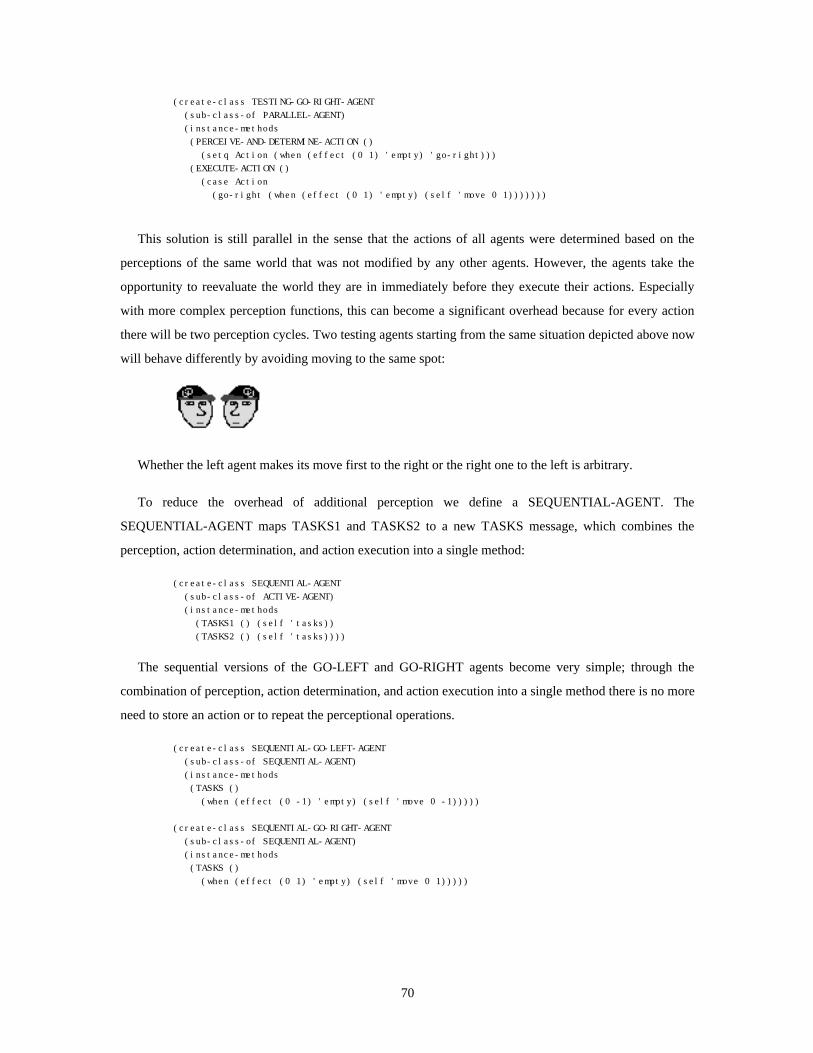
(create-class TESTING-GO-RIGHT-AGENT (sub-class-of PARALLEL-AGENT) (instance-methods (PERCEIVE-AND-DETERMINE-ACTION () (setq Action (when (effect (0 1) 'empty) 'go-right))) (EXECUTE-ACTION () (case Action (go-right (when (effect (0 1) 'empty) (self 'move 0 1)))))))
This solution is still parallel in the sense that the actions of all agents were determined based on the
perceptions of the same world that was not modified by any other agents. However, the agents take the
opportunity to reevaluate the world they are in immediately before they execute their actions. Especially
with more complex perception functions, this can become a significant overhead because for every action
there will be two perception cycles. Two testing agents starting from the same situation depicted above now
will behave differently by avoiding moving to the same spot:
Whether the left agent makes its move first to the right or the right one to the left is arbitrary.
To reduce the overhead of additional perception we define a SEQUENTIAL-AGENT. The
SEQUENTIAL-AGENT maps TASKS1 and TASKS2 to a new TASKS message, which combines the
perception, action determination, and action execution into a single method:
(create-class SEQUENTIAL-AGENT (sub-class-of ACTIVE-AGENT) (instance-methods (TASKS1 () (self 'tasks)) (TASKS2 () (self 'tasks))))
The sequential versions of the GO-LEFT and GO-RIGHT agents become very simple; through the
combination of perception, action determination, and action execution into a single method there is no more
need to store an action or to repeat the perceptional operations.
(create-class SEQUENTIAL-GO-LEFT-AGENT (sub-class-of SEQUENTIAL-AGENT) (instance-methods (TASKS () (when (effect (0 -1) 'empty) (self 'move 0 -1)))))
(create-class SEQUENTIAL-GO-RIGHT-AGENT (sub-class-of SEQUENTIAL-AGENT) (instance-methods (TASKS () (when (effect (0 1) 'empty) (self 'move 0 1)))))
70

I will not judge the usefulness of the different degrees of parallelism. Depending on the application
requirements one approach might be better than the others. Two-phase scheduling not only supports the
different approaches, it even supports the simultaneous use of the approaches.
Dining Agents
The interactive Dining Agents application is an Agentsheets implementation of the dining philosopher
problem [104]. All agents like to eat. In order to eat they need to grab two chop sticks. Once they are able
to grab two sticks they change from “thinking” mode to “eating” mode. The agents operate concurrently.
Simultaneously, users can interact with the agents. They can add and remove agents as well as chop sticks.
The Agentsheets scheduler guarantees mutual exclusion which prevents problems arising from the
concurrent operation of agents and possible user interventions. The scheduler warrants that agents will not
be interrupted by the user or other agents during critical sections. For example, it could be fatal if agents are
interrupted between counting chop sticks and grabbing them. Users will gain control over agents at the
earliest possible time.
The Figure 2-13 shows five agents with five chop sticks. Agents can grab adjacent sticks.
Figure 2-13: Five Thinking Agents with Five Chop Sticks
The upper right agent and the lower left agent grab two chop sticks each and start to eat. The remaining
stick cannot be used by any other agent. They have to wait and continue to think.
71

Figure 2-14: Two Eating and Three Thinking Agents with One Chop Stick Left
The challenge for a construction paradigm supporting participatory theater is to provide a scheduler that
is fine grained enough to evoke the illusion of concurrency. At the same time, the scheduler has to
guarantee mutual exclusion for agent and user processes without forcing the application designers to
explicitly deal with intricate synchronization mechanisms such as semaphores [35, 104] or monitors [65].
In other words, the granularity of parallelism is not just bound by technical limitations but also by the ease
of programming.
2.5. Metaphors as Mediators
In Agentsheets metaphors are mediators between the problem solving-oriented construction paradigm
and domain-oriented applications. The construction paradigm has to be evocative in order to support the
creation of spatial and temporal metaphors. The notion of autonomous agents organized in a grid is
suggestive for metaphors of space, time and communication. Additionally, participatory theater provides a
way for users to interact with spatio-temporal metaphors.
The essence of Agentsheets is to use the domain-independent construction paradigm to create new
spatio-temporal metaphors that reflect domain-oriented semantics of applications. In the circuits application
of Agentsheets (Figure 2-15), a designer has created a set of agents modeling the behavior of simple
electric components such as wire pieces, switches, bulbs, electromagnets, and electromagnetic switches. A
user creates a circuit from components. At any time a user can interact with the circuit (for example, by
opening and closing switches, adding and removing components).
72

Figure 2-15: Agentsheets Application: Circuits
The consistency between a real-world situation and a domain-oriented spatio-temporal metaphor is
controlled by the person creating the application-domain-tailored visual programming system. The circuits
application maps concepts like the connectivity of components and electromagnetic fields to the adjacency
concept, part of the “communicating agents sharing a structured space” metaphor. In Figure 2-15, a
solenoid is created simply by putting an electromagnet and an electromagnetic switch next to each other
(the electromagnet is above the leftmost switch in the bottom row of switches).
2.6. Defining Behaviors of Agents
Agentsheets includes four approaches to define the behavior of agents: programming using AgenTalk,
programming with graphical rewrite rules, programming by example, and programming by prompting.
2.6.1. Programming using AgenTalk
Programming using AgenTalk is the lowest level of agent programming. AgenTalk is an object-oriented
extension of Lisp [109] based on the OPUS system [93] enriched with spatial primitives. Due to the
general-purpose nature of the underlying implementation language, Common Lisp, this is the most flexible
way to program, but at the same time it is the most demanding approach to define behavior.
2.6.2. Programming with Graphical Rewrite Rules
The graphical rewrite rule approach (illustrated in the “The Agentsheets System In Use” section of this
Chapter) of programming allows the definition of simple behavior by manipulating pictures. Rewrite rules
73

have been explored before by Furnas [37] in the BitPict system, and by Bell [4-6] in ChemTrains. The
BitPict system is limited to graphically reason about pixels. ChemTrains can deal with more complex
objects such as boxes, circles, and entire bitmaps. Both BitPict and ChemTrains have no included abilities
to augment graphical rules with textual predicates. The Vampire system overcomes this limitation with
attributed graphical rules [73].
BitPict, ChemTrains, and Vampire work with the notion of a global rule set. A centralized algorithm
matches the rules in the rule set with the current picture. If the left-hand side of a rule is satisfied then the
rule will fire by executing the right-hand side of the rule. The graphical rewrite rule approach used in
Agentsheets makes use of decentralized rule sets. That is, each agent has its own set of rules. This localistic
rule matching has been used for Agentsheets because they simplify specialization and decomposability.
• Specialization: The specialization of individual objects’ behavior is complex because of the missing
association between global rules and individual objects. What rules could have implications for some
object to be specialized? How could these rules be modified without having unwanted side effects for
other objects?
• Decomposability: The behavior of an agent is completely defined by the set of rules owned by the agent.
Copying the agent in one application and putting it into another application is trivial because the agent
and its behavior are one unit. In the case of global matching, the act of copying a component from one
application to another one is complex because it is not clear, due to the lack of clear association between
rules and objects, what part of the global rules from application 1 should be copied into application 2.
This is not to say that localistic rules are generally superior to global rules. However, in the context of
autonomous agents the localistic rule approach is more appropriate because specialization and
decomposability are crucial features.
2.6.3. Programming by Example
The programming by example [16] approach employed by Agentsheets (Figure 2-16) can be viewed as
an extension of the graphical rewrite rule approach in the sense that programs are no longer created by
editing a separate entity called a rule. Instead, a so-called program acquisition agent directly observes the
user modifying artifacts and, similar to the agent in Object Lens [63], creates a program for the user. The
program contains spatial operations such as moving, deleting, or adding an agent as well as non-spatial
operations such as querying the attribute of some agent.
User operations are interpreted by the programming acquisition agent to create programs consisting of
if-then rules that get attached to the agents to be programmed. This process is different from classical
programming by example approaches because it features:
74

• Transparent Program Creation: Users see programs grow as they operate on the artifact. The program
can be edited explicitly by the user; and program fragments can be deleted, specialized or generalized
through a set of spatial transformation rules.
• Personalizable Programming Acquisition Agents: In addition to the ability to edit the created rule
directly, users can personalize programming acquisition agents by modifying spatial transformation
rules associated with acquisition agents.
Rule ofAgent to be extended
?
IF depiction (Bulb, off) and agent (Below, 1, 0) and has-voltage (Below)
THEN depiction (Bulb, burn)
AcquisitionAgentUser
Agentsheet
query
modify
observemodifications
observequeries
suggestjustification
suggestaction
add/removegeneralize/specializejustification/action
Figure 2-16: Programming by Example
2.6.4. Programming by Prompting
An approach much simpler than programming by example but for many problems quite effective is the
programming by prompting approach. This approach is similar to programming by rehearsal [26] and is
based on a theatrical metaphor in which agents are actors that sometimes do not know what to do. In these
situations the prompter will help the actor by supplying the appropriate line. If, through some operation by
the user, some agent is sent a message for which the agent has no matching method, then the user gets the
opportunity to fill in some appropriate action into a method template. The difference to programming by
rehearsal is that in programming by prompting the user plays a more opportunistic role of an occasional
prompter instead of a director. That is, the user does not know how far the actors can go without help. As
much information as possible is derived from the context in which the prompting occurred (the class of the
receiving agent, the message name, and arguments of the message sent). Just as in the programming by
75

example approach, the definition of functionality in programming by prompting is not driven by some top-
down design strategy but, instead, by actual usage situations in some early evolving prototype.
2.7. The Agentsheets System In Use
This section illustrates typical use situations of Agentsheets. Three simple scenarios are provided to
show how end-users run an Agentsheets application, how a designer creates the look of agents, and how a
designer defines the behavior of an agent.
2.7.1. Scenario 1: End-User Running an Existing Agentsheet Application
The end-user opens an existing Agentsheets application called channels. This application deals with the
distribution of water in a system of pipes. Two windows appear on the screen (Figure 2-17). The gallery
(left window) contains water channels agents. The look as well as the behavior of these agents (pipe agents,
valve agents, etc.) were defined by the visual programming system designer. The worksheet (right window)
is empty so far.
Figure 2-17: Agentsheets Environment
The user’s goal is to set up a simple topology of pipes. The user selects a water source in the gallery and
places it into the worksheet:
Horizontal pipes get attached by first selecting the horizontal pipe in the gallery and then clicking into
the worksheet. Dragging the mouse horizontally in the worksheet will create the desired layout of pipe
components:
76

Finally, a sink gets attached to the last pipe agent to prevent the water leaking into the Agentsheet:
Stimulating the water source enables the flow of water through the pipe system:
The system does not have a centralistic notion of water flow. Nor does the picture ever get parsed or
compiled into a static representation. Instead, the agents are autonomous units, each dealing with a very
localistic view of the (channel) world. Every agent has a very simple behavior. A horizontal pipe agent, for
instance, will propagate water that enters it from left to right. The pipe agents got connected implicitly by
being placed next to each other. In other words, there was no need for explicit connections by drawing links
between components, as in a dataflow graph. Hence, the user can alter the pipe system easily. For instance,
the user could break up the system by dragging a piece of pipe away and replacing it with a valve:
The valve can be operated by clicking at it. The valve opens and propagates the water. At the same time
the valve plays the sound of a large opening valve to provide additional feedback to the user.
77

Assuming that each pipe agent models a non-ideal segment of pipe (evaporation), then even in a more
complex channel topology, like the one below, the user can determine water flow differences between any
two points in the system without ever having to determine the distances between nodes explicitly.
2.7.2. Scenario 2: A Visual Programming System Designer Creates the Look of Agents
The visual programming system designer has to define the look of agents such that an end user will
recognize them. To a large degree this process depends on the drawing skills of the designer. However,
Agentsheets enables the designer to define the look of agents incrementally by means of graphical
inheritance. Let us assume that our goal is to build a horse riding simulation. First we start out drawing a
horse using the Agentsheets bitmap editor:
The bitmap editor, like the gallery, is in fact just another agentsheet. Every pixel of the bitmap is
represented by an agent. Clicking at the agent will flip its color from white to black or vice versa. The
finished horse becomes the first entry into our gallery. The designer now likes to create two variants of the
horse; a riderless horse and a swimming horse. In addition to storing agent depictions, galleries also support
the cloning of depictions. Cloning a depiction will create a new depiction preserving a cloning relationship
to the original depiction. We clone our initial horse:
78

The rider and no-rider versions of the horse depiction look identical. The arrow between the depictions
indicates a cloning relationship. Now, the rider gets removed from the non-rider horse depiction via the
bitmap editor.
The swimming horse gets added the same way.
The purpose of the gallery is to manage the cloning relationships between agent depictions. Changes
added to a depiction can be propagated to its clones. Furthermore, cloning relationships may include
transformations like rotation, flipping, boolean combination, negation, etc. Using these transformations, the
channel gallery was composed from just two basic depictions.
79
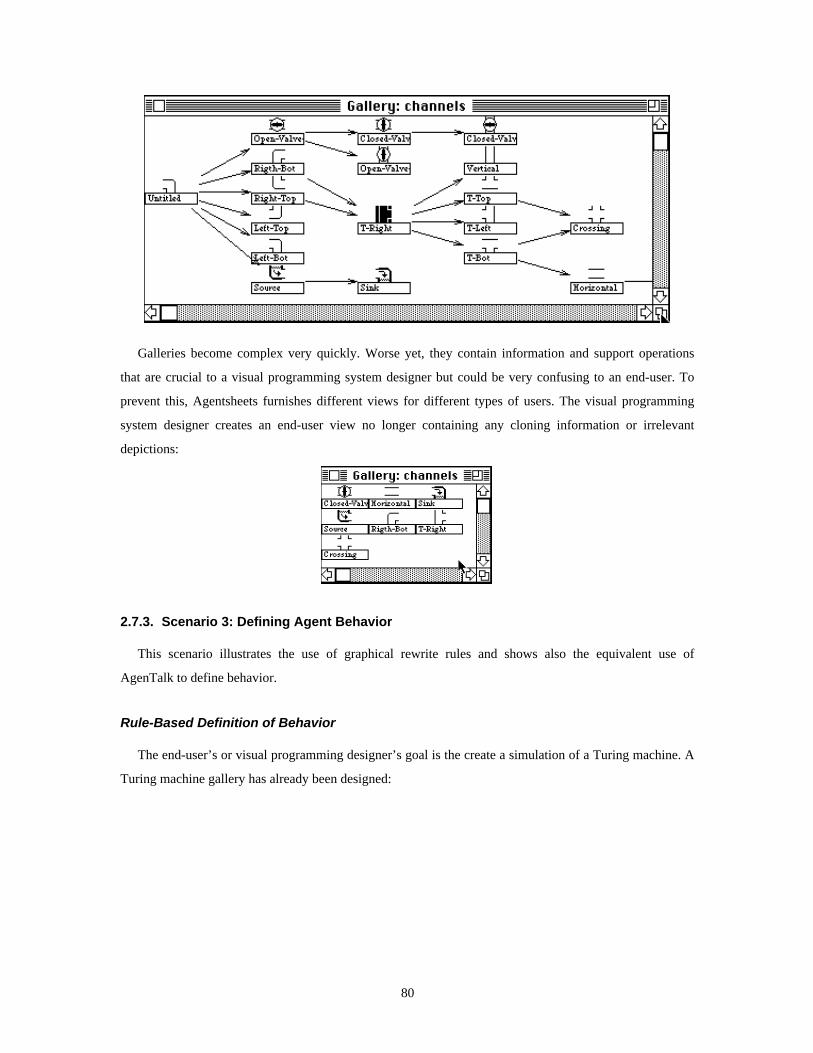
Galleries become complex very quickly. Worse yet, they contain information and support operations
that are crucial to a visual programming system designer but could be very confusing to an end-user. To
prevent this, Agentsheets furnishes different views for different types of users. The visual programming
system designer creates an end-user view no longer containing any cloning information or irrelevant
depictions:
2.7.3. Scenario 3: Defining Agent Behavior
This scenario illustrates the use of graphical rewrite rules and shows also the equivalent use of
AgenTalk to define behavior.
Rule-Based Definition of Behavior
The end-user’s or visual programming designer’s goal is the create a simulation of a Turing machine. A
Turing machine gallery has already been designed:
80

A Turing machine can be modeled by a head moving on a tape of symbols. The designer has prepared a
worksheet containing a tape and a head.
The behavior of an agent may be defined by attaching graphical IF-THEN rules to it. By double-clicking
the head of the Turing machine, the designer gets a two dimensional rule editor (another agentsheet).
IF THEN
The rule editor contains two 3x3 blocks of agents. The left block represents the IF part of the rule and
the right block represents the THEN part. The desired rule should make the head move to the right on a “0”
tape piece. The designer removes unnecessary context in the IF and THEN part, and finally moves the head
one position to the right in the THEN part.
After the designer accepts the rule the head of the Turing machine will move to the right until it is on
top of a non “0” piece of tape.
A second rule is attached to the head using the rule editor replacing “1”s with “0”s.
81

The head moves in the worksheet to the end of the tape.
Now we write a rule extending the tape with more “0”s.
This will extend the tape until the head and the tape pieces leave the agentsheet.
AgenTalk-Based Definition of Behavior
The definition of behavior through graphical rules has its limitations. For instance, most numerical
applications are better expressed textually. The textual equivalent of the “move to the right on 0” graphical
rule using AgenTalk is:
(create-class TURING-MACHINE-HEAD-AGENT (sub-class-of ACTIVE-AGENT) (instance-methods (TASKS () (when (equal (effect (1 0) 'depiction) 'tape-0) (self 'move 0 1)))))
2.8. Related Systems
This section describes systems - in the contexts of the four contributions - that are related to
Agentsheets. All systems include construction paradigms to support programming as problem solving,
participator theater, and metaphors as mediators in one way or another. These systems share the intent of
extending the notion of programming languages with the notion of a programming medium.
82

Table 2-2: Agentsheets and Related Systems
Contributions
Systems
Programming as ProblemSolving
What mechanisms areprovided to incrementallycreate spatial and temporalrepresentations?
Participatory Theater
What parts of the continuousspectrum of control and effortare supported?
Metaphors as Mediators
What kind of metaphors arebuilt-in or anticipated?
Agentsheets
[92, 94-96]
• implicit representationsbased on agents organizedin grid
• explicit representations(e.g., links between agents)
• behavioral specialization(OOP inheritance)
• spatial specialization(cloning)
• direct manipulation
• programmable (Lisp,AgenTalk, Graphical RewriteRules, By Example, ByPrompting)
• agent scheduler supportingautonomous behavior ofagents and directmanipulation by usersimultaneously
autonomous agentsorganized in grid evokespatio-temporal metaphors(flow, hill climbing,opposition, Microworld,personality, evolution,containment, etc.)
ACE
[60, 83, 84]
visual formalisms representvisual structures of contentthat can be specialized(e.g., task-specificspreadsheet cells)
• direct manipulation
• programmable (formulas,Lisp, C)
• no built in mechanism to dealwith autonomous behavior
• visual formalisms (tables,graphs, outlines)
• no provision to createtemporal metaphors such asflow
Boxer
[1, 19-21]
data and programs can berepresented as nested boxes
• direct manipulation
• programmable (Logo)
• “learning by cheating” directmanipulation of programcontrolled parts
spatial metaphor forstructure: containment ofboxes
ChemTrains
[4, 6]
spatial representations aredefined with graphicalrewrite rules
• direct manipulation
• programmable (graphicalrewrite rules)
• users and rule inferenceengine can change diagramssimultaneously
metaphors based oncontainment andconnectedness
*Logo
[97]
each turtle is represented byone pixel
• no direct manipulation ofturtles
• programmable (*Logo)
spatio-temporal metaphor:micro worlds consisting ofturtles and patches
NoPumpG
[68, 115]
fixed set of drawingprimitives
• direct manipulation
• programmable (formulas)
• timer cells for autonomousbehavior
“liberated” spreadsheet cellsmetaphor
Piersol’s OOSS
[90]
objects in cells can berefined by subclassing(Smalltalk [43, 44])
• direct manipulation
• programmable (formulas,Smalltalk)
spreadsheet extension
SchemePaint
[23]
high level drawingprimitive can be capturedby libraries
• direct manipulation
• programmable (Scheme)
• no built in mechanism to dealwith autonomous behavior
spatial metaphor: singleturtle
MAGES [9] is a system that is highly related to Agentsheets with respect to the notion of agents that are
organized in a grid. However, applications intended with MAGES are of a very different nature than the
systems described. MAGES is used as testbed for heterogeneous agents. It does not provide mechanisms to
support programming as problem solving, nor does it facilitate participatory theater.
83

CHAPTER 3EXPERIENCE: METAPHORS ARE MEDIATORS BETWEEN APPLICATIONS
AND CONSTRUCTION PARADIGMS
We usually see only the things we are looking for.
- Eric Hoffer
Overview
This chapter is about the experience gained from people using Agentsheets. It describes a number of
Agentsheets applications in the context of the four major contributions of this dissertation by relating them
back to the theoretical framework discussed in Chapter 1 and to design decisions explained in Chapter 2.
The previous chapters have introduced the view of programming as problem solving. Agentsheets
adopts this view by including a construction paradigm that supports the design and the modification of
spatial representations. But what is the nature of these spatial representations? Do spatial representations
share common principles that are independent of the domain in which they are used?
I will make the point that applications created with Agentsheets or with any other mechanism supporting
the creation of dynamic spatial representations - represent their domain through the use of metaphors. That
is, applications based on spatial representations are typically not created by mapping characteristics of a
problem domain to arbitrary spatial properties provided by a programming environment. Instead, they make
use of metaphors that can be applied to the problem domain and that are supported by the representation
medium.
Metaphors are the middle ground between problem domains and the tools representing those domains.
The focus of this chapter is on analyzing the role played by metaphors in problem solving. How do
metaphors help to bridge the gap between the envisioned problem domains (including knowledge-based
simulation environments, artificial life environments, visual programming languages, programmable
drawing tools, board games, complex cellular automata, and iconic spreadsheet extensions) and the
construction paradigm featured by Agentsheets?
I place the applications described in groups that share underlying metaphors. I then argue for two
conclusions, based on this presentation: First, the Agentsheets design is successful in supporting a very
wide range of applications. Second, Agentsheets permits application developers to represent and use
common organizing metaphors, as illustrated within the groups of applications.
84

3.1. The Role of Metaphors as Mediators
Problem solving includes the continuous change of representation until the solution of the problem to be
solved becomes transparent [105]. In many cases representations become transparent when they express
information in ways analogous to familiar situations. In other words, representations can be metaphors.
Many programming paradigms employ metaphors. Data flow [53, 58, 116] and control flow [62], for
instance, make use of flow metaphors. Metaphors help us to learn about things we do not yet understand by
creating analogies to things we do understand [64].
Metaphors bridge the gap between domain-oriented dynamic visual environments, i.e., the Agentsheets
applications and the problem solving oriented construction paradigm featured by Agentsheets. The
intricacies of a domain-oriented dynamic visual environment are not mapped directly to the notion of
agents and agentsheets. Instead, metaphors are used as mediators between the two levels of representation.
Figure 3-1 below shows the relationships among the application layer, metaphors, and the construction
paradigm layer. A relatively small number of metaphors can be re-used as representation for a large
number of applications (the applications are explained in detail in the following sections). All metaphors
are implemented in terms of the construction paradigm.
85
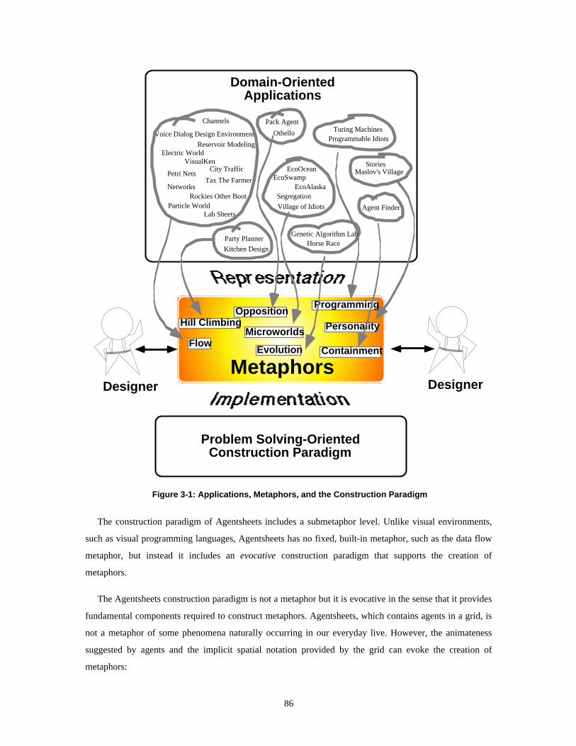
Channels
Reservoir ModelingElectric World
VisualKenCity Traffic
Petri Nets
NetworksTax The Farmer
Particle WorldRockies Other Boot
Voice Dialog Design Environment
Lab Sheets
Party Planner
Kitchen Design
Pack Agent
Othello
EcoOceanEcoSwamp
EcoAlaskaSegregation
Village of Idiots
StoriesMaslov's Village
Turing MachinesProgrammable Idiots
Horse Race
Agent Finder
Domain-OrientedApplications
Metaphors
Problem Solving-OrientedConstruction Paradigm
Flow
Hill ClimbingMicroworlds Personality
Evolution Containment
OppositionProgramming
Genetic Algorithm Lab
Designer Designer
Figure 3-1: Applications, Metaphors, and the Construction Paradigm
The construction paradigm of Agentsheets includes a submetaphor level. Unlike visual environments,
such as visual programming languages, Agentsheets has no fixed, built-in metaphor, such as the data flow
metaphor, but instead it includes an evocative construction paradigm that supports the creation of
metaphors.
The Agentsheets construction paradigm is not a metaphor but it is evocative in the sense that it provides
fundamental components required to construct metaphors. Agentsheets, which contains agents in a grid, is
not a metaphor of some phenomena naturally occurring in our everyday live. However, the animateness
suggested by agents and the implicit spatial notation provided by the grid can evoke the creation of
metaphors:
86

• Spatial Metaphors: The spatial organization of agents in an agentsheet endorses metaphors of space. A
large number of spatial metaphors can be mapped to spatial relations between agents such as topological
relations (e.g., proximity, order, enclosure, continuity), and Euclidean relations (angularity, parallelism,
and distance).
• Temporal Metaphors: Agents are autonomous, active entities that are aware of time. They can use this
awareness to express metaphors that depend on time.
• Communication Metaphors: The communication mechanisms built in to the Agentsheets construction
paradigm support metaphors of communication.
• Interaction Metaphors: Agentsheets supports the participatory theater metaphor, which accounts for
direct manipulation as well as delegation.
• Psychological Metaphors: Many Agensheets applications have employed agents as naive models for
human beings. Behavior emerging from a collective of interactive agents is often perceived in
psychological terms such as aggressive, passive, or lazy.
In the following subsections I will describe several different Agentsheets applications and how they
combine and specialize metaphors. The applications are categorized by the type of metaphor used. Most
applications would fit into multiple metaphors. In these cases the application were categorized into the
predominant metaphor class. The aggregated metaphors are:
• Flow: Flow combines spatial, temporal, and interaction metaphors. Flow describes the smooth,
continuous movement of some substance or, more typically, of a stream of substance in some media.
The flow can be guided, in which case we talk about the media as being a conductor.
• Hill Climbing and Parallel Hill Climbing: Climbing combines spatial, temporal, and interaction
metaphors. Agents will try to improve their satisfaction by incrementally moving toward “better” places.
In parallel hill climbing, multiple agents will move to increase their satisfaction.
• Opposing Agents: Opposing agents work against users and challenge them to the greatest degree
possible. Typical applications are games.
• Agent Microworlds: Agent microworlds are simple models of humans or animals interacting with each
other directly or through some shared environment.
• Agents with Personality: Agents with personalities do not just emerge from low-level programmed
behavior but are explicitly built in using models such as Maslow’s model of the hierarchy of human
needs.
• Programmable Agents: Programmable agents are agents with built in mechanisms to define simple
behavior graphically.
87

• Evolving Agents: The behavior of agents can be captured with a gene mapping a set of possible
perceptions to a set of possible reactions. Users guide the evolution of behavior by selecting agents with
promising behaviors and crossing their genes.
• Agent Containers: Agents can be containers of other agents. Containment can be recursive.
3.2. Metaphors of Flow
Flow is one of the most important metaphors in Agentsheets, combining the spatial and temporal aspects
of agents. The abstract concept of flow describes the smooth, continuous movement of some substance or,
more typically, of a stream of substance in some media. This section illustrates important characteristics of
flow and ways to map different types of flow onto the notion of autonomous agents. The mappings
provided are not exhaustive; that is, there are many more, but less intuitive, alternatives.
• Flow Conduction : If the media through which the substance is flowing guides or constrains the flow,
then we refer to the media as a conductor. Water flow in a lake caused by wind blowing over the water
surface is not constrained by the media, i.e., the lake. We do not consider a lake to be a conductor of
water flow. A river or an electric wire, on the other hand, clearly directs flow. Hence, rivers and wires
are conductors.
Mapping: Conductors are represented by adjacent agents or with links between agents.
• Flow Control: What are the mechanisms built in to the metaphor to control the flow (if any)? For
instance, how can the flow be increased or decreased?
Mapping: Flow control agents are typically specializations of conductor agents.
• Flowing Substance: What is flowing? The notion of flow is not limited to physical substances such as
water. Mental substances, such as ideas, information, control and time, can flow as well.
Mapping: If the flowing entities (mental or physical) are supposed to have visible manifestations then
they are mapped to agents. Otherwise, they are mapped to messages.
• Animateness of Flowing Substance (passive, self propelled): In passive flow an external force, such as
gravity, causes entities to move. In active flow, on the other hand, animated entities have the ability to
initiate self motion. For instance, in traffic flow cars are the animated entities able to self propel due the
their built-in engines.
Mapping: Passive agents wait for messages representing forces applied to them and then react by
moving. Active agents, for instance agents representing cars, take the initiative to move.
• Distribution and Collection of Flow: Conductors can be distributors and collectors. The most simple
conductor topology is a straight connection that moves entities from a source to a destination. More
generally, however, conductors can also distribute flow from one source to many destinations or collect
88
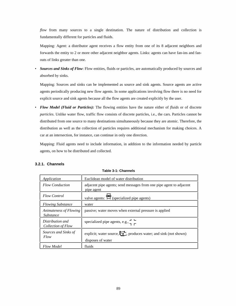
flow from many sources to a single destination. The nature of distribution and collection is
fundamentally different for particles and fluids.
Mapping: Agent: a distributor agent receives a flow entity from one of its 8 adjacent neighbors and
forwards the entity to 2 or more other adjacent neighbor agents. Links: agents can have fan-ins and fan-
outs of links greater than one.
• Sources and Sinks of Flow: Flow entities, fluids or particles, are automatically produced by sources and
absorbed by sinks.
Mapping: Sources and sinks can be implemented as source and sink agents. Source agents are active
agents periodically producing new flow agents. In some applications involving flow there is no need for
explicit source and sink agents because all the flow agents are created explicitly by the user.
• Flow Model (Fluid or Particles): The flowing entities have the nature either of fluids or of discrete
particles. Unlike water flow, traffic flow consists of discrete particles, i.e., the cars. Particles cannot be
distributed from one source to many destinations simultaneously because they are atomic. Therefore, the
distribution as well as the collection of particles requires additional mechanism for making choices. A
car at an intersection, for instance, can continue in only one direction.
Mapping: Fluid agents need to include information, in addition to the information needed by particle
agents, on how to be distributed and collected.
3.2.1. Channels
Table 3-1: Channels
Application Euclidean model of water distribution
Flow Conduction adjacent pipe agents; send messages from one pipe agent to adjacentpipe agent
Flow Control valve agents: (specialized pipe agents)
Flowing Substance water
Animateness of FlowingSubstance
passive; water moves when external pressure is applied
Distribution andCollection of Flow
specialized pipe agents, e.g.,
Sources and Sinks ofFlow
explicit; water source, , produces water; and sink (not shown)
disposes of water
Flow Model fluids
89

Figure 3-2: Channels
The information captured in Figure 3-2 is not just of a topological nature. Additionally, the diagram
includes Euclidean information. For instance, there will be a difference, in terms of the time it takes to flow
through, between a long pipe constructed from a large number of agents and a short pipe consisting of only
a small number of agents. The Euclidean distance may have important physical implications. For instance,
if each agent models an imperfect piece of pipe that loses a certain percentage of water in the process of
transporting it, then a collective of agents can be used to correctly infer the loss of water between any two
points in the system.
3.2.2. Reservoir Modeling
A different approach has been used for river and reservoir modeling. Agentsheets links are conductors
for water between reservoirs (represented by the triangles in the worksheet in Figure 3-3). Links indicate
just topological information. That is, the locations of the reservoirs as well as the length of the links
between the reservoirs are irrelevant. The two folder-like agents are used to collect data. Between the two
folders is a mapping agent that can be programmed to convert one sequence of data into another.
90

Table 3-2: Reservoir Modeling
Application Topological model of water distribution
Flow Conductionlinks conduct water between large reservoirs;
Flow Control part of reservoir; users can define outflow parameters
Flowing Substance water
Animateness of FlowingSubstance
passive; water moves when external pressure is applied
Distribution andCollection of Flow
through multiple links leaving or coming in to reservoir
Sources and Sinks ofFlow
explicit; water source produces water and sink disposes of water
Flow Model fluids
Figure 3-3: Reservoir Modeling
3.2.3. Electric World
The Electric World application features two types of flow: the flow of electricity and the flow of
magnetic fields. Both flow types coexist without influencing each other. The agent above the leftmost
switch in the bottom row of switches in Figure 3-4 is an electric coil that emits an electromagnetic field if
91

current is flowing through the coil. The coil and the bulbs are implicitly grounded. A switch sensitive to
electromagnetic fields is located on the left of the coil. The combination of coil and electromagnetic switch
results in a solenoid.
Table 3-3: Electric World
Application Model of electric current and electromagnetic fields
Flow Conduction two types of flow: 1) electricity: through adjacent wire agents, 2)electromagnetic: through adjacent agents of any type
Flow Control 1) electricity: through specialized wire agents, e.g., ,
2) electromagnetic: no distribution and collection
Flowing Substance electricity and electromagnetic fields
Animateness of FlowingSubstance
passive; fields are result of external energy
Distribution andCollection of Flow
1) electricity: switch agents:
2) electromagnetic: no control
Sources and Sinks ofFlow
1) electricity: power supply
2) electromagnetic: coil
Flow Model fluids
Figure 3-4: Electric World
92

3.2.4. VisualKEN
The VisualKEN application is a visual programming front end to an expert system [114] based on
control flow. Control is considered a discrete entity that cannot be distributed. If control hits a distributor,
i.e., an entity connecting one source with multiple destinations, such as the case statement represented by
the right-hand window in Figure 3-5, then an explicit choice needs to be made. For instance, in the case
statement, control can either flow down if the value associated with control matches the number depicted or
flow to the right otherwise.
Table 3-4: VisualKEN
Application Visual programming front end to expert system
Flow Conduction adjacent flow agents (wires, statements)
Flow Control Because flow is discrete, only the direction of flow is controlled and notmagnitude (see Distribution and Collection of Flow)
Flowing Substance location of control
Animateness of FlowingSubstance
controlled partially by user (if control flow reaches user input boxes)
Distribution andCollection of Flow
choices need to be made because control is discrete; there is only onepoint of control.
Distributor example:
Sources and Sinks ofFlow
controlled by user defining the current location of control by clicking atagents.
Flow Model particle (discrete)
Figure 3-5: VisualKEN
93

3.2.5. City Traffic
City Traffic is a traffic construction kit designed to experiment with different road topologies and to
study the implications of traffic signs to the flow of traffic.
The entities flowing (the cars) and the conductors (the road pieces) are agents (Figure 3-6). Road
intersections can be flow distributors as well as flow collectors depending on the direction of the flow. Cars
are discrete and can, therefore, not be distributed by a distributor. Furthermore, the collection of flow is
problematic (car crash).
Table 3-5: City Traffic
Application City traffic construction kit
Flow Conduction adjacent road agents
Flow Control
indirect through traffic signs such as , or ; if cars really stopdepends on the behavior of their drivers, who may simply ignore trafficsigns
Flowing Substance car agents
Animateness of FlowingSubstance
autonomous; car agents model people driving cars and making decisionson where to go next
Distribution andCollection of Flow
intersections, e.g.,
Sources and Sinks ofFlow
user: the user creates and deletes cars
Flow Model particle (discrete)
Figure 3-6: City Traffic
94

3.2.6. Petri Nets
Petri Nets are used to model parallel processes. Tokens reside in places (the circles in Figure 3-7).
Places are connected with each other. The tokens flow from one place to another place through a transition
that must be fired. Tokens, places, and transitions are agents.
The flow in Petri Nets has a special semantics. Transitions are collectors and distributors not adhering to
the principle of particle conservation. The principle of particle conservation states that a conductor moves
particles without preserving their number. This is plausible for most particles representing physical entities
such as cars. Petri Net transitions are active conductors that not only transport entities but also can produce
new ones or remove old ones.
Table 3-6: Petri Nets
Application Model parallel processes
Flow Conduction places , containing tokens, are connected to other places via linksand transitions .
Flow Control flow is controlled by transitions that fire under certain conditions.A transition can fire when all incoming links lead to places containingat least one token. A firing transition will remove one token of eachplace pointing to the transition and it will place one token in each placepointed to be the transition.
Flowing Substance tokens
Animateness of FlowingSubstance
token are passive particles moved by active transitions
Distribution andCollection of Flow
through transitions with fan-ins or fan-outs larger than 1.
Sources and Sinks ofFlow
initial tokens are produced by user. Additionally, tokens can be added orremoved by transitions.
Flow Model discrete
Figure 3-7: Petri Nets
95

3.2.7. Networks
The purpose of the network applications to design and simulate computer networks (Figure 3-8).
Table 3-7: Networks
Application Design, simulation and maintenance of computer networks
Flow Conduction adjacent network agents; different network types coexist such as thinwire and thick wire Ethernet and AppleTalk.
Two flow types: network configuration flow is used for the genericnetwork to adapt to specific requirements dictated by network topology;packet flow simulates actual network traffic between computers andperipheral devices.
Flow Control different packet flow protocols require gateways (flow converters),and repeaters
Flowing Substance network configuration flow , packets
Animateness of FlowingSubstance
passive
Distribution andCollection of Flow specialized network agents, e.g.,
Sources and Sinks ofFlow sources: active network components such as computers
sinks: other computers or passive components such as printers:
Flow Model fluids: despite their seeming discreteness, the packets really behave likewave fronts of fluids. Consequently, packets are distributed bydistributors like fluids.
Figure 3-8: A Network Design with of Two Network Zones
96

3.2.8. Tax The Farmer
How should a farmer be taxed for water pollution on the basis of the land topology? Pollutants of
farming land are is washed into nearby rivers by rain. The amount of pollution washed into the river
depends on the land topology. This amount needs to be determined in order to tax the farmer accordingly
and to predict the needs for treatment plants (Figure 3-9).
Table 3-8: Tax The Farmer
Application Water pollution model
Flow Conduction adjacent land patch agents
Flow Control water drop agents on a patch of land move in the direction of descent
Flowing Substance water drops
Animateness of FlowingSubstance
active; the water drops are chemical agents engaging into disolvementprocesses.
Distribution andCollection of Flow
rivers collect water drops
Sources and Sinks ofFlow
drops are created explicitly by users; rivers serve as drop sinks
Flow Model water drops are considered particles (discrete)
Figure 3-9: Farming Land with Raindrops and River
97

3.2.9. Particle World
In this naive physics model movable and fixed particles interact with each other through
collisions (Figure 3-10).
Table 3-9: Particle World
Application Naive physics model.
Flow Conduction no conductor; movable particles can flow freely in air unless constrainedby fixed or other movable particles
Flow Control fixed particles can be arranged to control flow
Flowing Substance movable particles
Animateness of FlowingSubstance
passive; movable particles are propelled by gravity
Distribution andCollection of Flow
particles are discrete; if there are several options then particles useprobabilistic models to make decision.
Source and Sinks ofFlow
particles are created and deleted by user
Flow Model particle (discrete)
Figure 3-10: Particle World
98

3.2.10. Rocky’s Other Boot
Rocky’s Other Boot is an educational environment for students to learn about causality and digital
circuits (Figure 3-11). A teacher gives the students tasks to design circuits that can detect a certain set of
spatial features of targets. Students assemble circuits from individual gates (And, Or, Timer, ...).
Table 3-10: Rocky’s Other Boot
Application Circuit design environment with build-in voice explanation. In explainmode, the flow of signals through the network of gates triggers spokensituated localistic explanations. Every gate agent explains itself in thecorrect sequence of flow. The explanations include the description thatthe agent is currently in and its reaction based on the associatedbehavior.
Flow Conduction wire agents
Flow Control gates, such as OR gates , propagate electrical signals depending ontheir inputs and their functional definition. More complex gates, such as
clock devices , include an internal state.
Flowing Substance electrical signals
Animateness of FlowingSubstance
passive
Distribution andCollection of Flow specialized wire agents, e.g.,
Sources and Sinks ofFlow A launch pad sends signals to spatial feature detectors such as the
cross detector . The feature detectors send an electrical signalthrough wires and gates.
Flow Model fluids
Figure 3-11: A Circuit Designed with Rocky’s Other Boot
99

3.2.11. Voice Dialog Design Environment
Voice dialog is used to design complex phone-based user interfaces (Figure 3-12) [96]. Designer and
customers of U S West can use this visual language to quickly prototype the very constrained interaction
between people and information services through phones. The visual language includes speech output and
touch-tone button input.
Voice dialog applications are a relatively new design domain. Typical applications include voice mail
systems, voice information systems, and touch-tone telephones as interfaces to hardware. Involvement in
this field was part of a collaborative research effort between the University of Colorado and U S West’s
Advanced Technologies Division. Designers within U S West presented a compelling case as to why the
voice dialog domain would be an excellent framework for pursuing our research. The designers were facing
challenging design problems - innovation and increasing complexity within the voice dialog application
domain was making it harder to design and develop products within the necessary time and cost constraints.
Table 3-11: Voice Dialog Design Environment
Application Voice dialog
Flow Conduction through adjacent agents and through links
Flow Control if the control flow enters a menu then the control of flow is determinedby the user pressing a phone button.
Flowing Substance point of control
Animateness of FlowingSubstance
passive
Distribution andCollection of Flow
because control is considered a discrete entity, flow cannot bedistributed; an explicit choice must be made by user or system
Sources and Sinks ofFlow
users can place point of control by clicking. Every component can be asource. Every component not leading to further components is a sink.
Flow Model particle
Figure 3-12: Voice Dialog
100

3.2.12. Labsheets
Figure 3-13 illustrates LabSheets, a data flow model similar to LabView [53].
Table 3-12: Labsheets
Application Data flow model similar to LabView [53].
Flow Conduction links
Flow Control components can modify data
Flowing Substance data; typically numerical values
Animateness of FlowingSubstance
active
Distribution andCollection of Flow
components can have fan-ins and fan-outs larger than 1. Somecomponents require an exact number of inputs; others can deal with aminimum number of inputs. The collection process includes operations
such as multiplying the input signals . The result of the operationgets distributed via all outgoing links to further components.
Sources and Sinks ofFlow spreadsheet-like input cells are typical sources of numerical values;
output cells are typical sinks of data
Flow Model fluids
Figure 3-13: A LabSheet
3.3. Hill Climbing and Concurrent Hill Climbing Metaphors
Hill climbing agents try to improve their situation by climbing up a conceptual hill representing their
“happiness.” Each agent will probe each of its 8 immediate neighbor locations, determine the happiness at
each location, and compare it with the current happiness. If any of the neighbor locations promises an
increased happiness, then the agent will move there.
The hill-climbing process is complex because the landscape implicitly defined by the evaluation
function may lead the agent into local maxima, leaving the agent unaware of even better places to be in.
Furthermore, typical Agentsheets hill-climbing applications employ multiple hill-climbing agents at the
101

same time. Because most agents define their happiness in terms of the location of other agents, “happiness”
literally becomes a moving target.
The participatory theater human-computer interaction approach helps to find interesting situations. Hill
climbing cannot guarantee finding an optimal solution to a problem. The even larger complexity of parallel
hill climbing could lead one to the conclusion that the solution process is so complex that it becomes
useless because the outcome of a solution is close to unpredictable. However, there are two reasons why the
situation is not quite as hopeless due to the problem-solving supporting nature of Agentsheets:
• The hill-climbing process has an intrinsic spatial manifestation: The hill-climbing agents are visible in
the worksheet. Hence, the situation the agents are in can be inspected visually by the user.
• Dynamic properties can be observed: Even if there is no static solution, i.e., the agents may never settle
down and may keep on moving, dynamic properties of the solution-finding process can be experienced.
For instance, agents may engage in cycles, such as moving in certain repetitive patterns. These dynamic
properties can be experienced only in a dynamic environment.
• Participatory theater can turn into a tactile experience of the solution space: The participatory theater
interaction scheme enables users to interact with the problem-solving process. Hill climbing is the
implicit script handed out to the actors determining the play. Users can be a passive audience but can
also take the initiative during the play and steer the hill-climbing process. For instance, they can help
agents to move out of a local maximum, or they can change the environment of agents or modify
parameters of the agent. In its most extreme case, participatory theater can become a tactile experience.
The solution space for even simple parallel hill-climbing problems is very complex and cannot be
conveyed directly. Instead, the combination of forces, one force being the direct manipulation and the
other force being the action determined from hill climbing, results in the tactile experience of the
problem space. In other words, the problem space is perceived by touching the its components.
The party agents planner and the kitchen design environment are two Agentsheets applications that
combine hill climbing with participatory theater into a tactile experience.
3.3.1. Party Agents Planner
The party agents planner, inspired by Rich Gold [17] , deals with the optimal arrangement of people (or
agents) at a party. Every agent at the party likes the other agents at the party to some degree, captured by
the so-called social distance. According to behavioral scientists, social distance is an indicator for the ideal
physical (Euclidean) distance between people. The need to be close to somebody reflects liking somebody.
Every agent at any point in time is trying to optimize its happiness by being as close to the other agents
of interest as implied by the social distance; close to the liked agents and far away from the disliked agents.
102

One of the dilemmas arising from this process includes; moving close to some liked agents may increase
the distance to some other liked agent or decreases the distance to some other disliked agent.
The situation depicted in Figure 3-14 contains 4 agents. Three agents are involved in a complex
triangular relationship: A: , B: and C: where A likes B but B hates A, B likes C but C hates B,
and C likes A but A hates C. None of the agents involved in this relationship will ever become completely
happy because the agents, interests are not mutual. Consequently a very complex dynamic behavior will
arise, leading to a wild chase of agents. A fourth agent, called the “party pooper” , is introduced. The
pooper likes everybody else but, at the same time, is hated by everybody.
Unlike in the original party planner by Gold described by Dewdney [17] the users can participate in the
party theater. For instance, the chase, resulting from the relationships among A, B, and C, can be influenced
by the user by moving agents to new locations, changing social distances, looking agents up (by building
walls around them) or introducing new agents.
Figure 3-14: An Agent Party
The party planner is a specific instance of a very general principle related to the hill-climbing metaphor.
For instance, a forester wished to use the party planner to plant trees. There are intricate compatibility
problems among different types of trees. The idea was to use the party planner to determine good planting
topologies of mixed tree type forests.
103

3.3.2. Kitchen Planner (Tactile Critiquing)
The hill-climbing metaphor can be used as a constructive design force. In the kitchen planner,
appliances such as sinks , refrigerators , and ovens , are active components that try to
maximize their happiness (Figure 3-15). Design knowledge provided by users in the form of spatial
relationships that reflect kitchen design guidelines gets attached to components. But unlike in critiquing
systems such as Janus [32], the knowledge is constructive and not just evaluative. That is, guidelines can
only be used not only to critique an existing situation but, additionally, they can suggest improvements.
Constructive knowledge can drive hill climbing. Evaluative knowledge typically consists of predicates
returning a true or false value based on the situation the predicates fire in. For instance, a predicate used in
Janus called GOOD-WORK-TRIANGLE returns a true value if the total distance from the oven, to the
refrigerator to the sink is less than 22 feet. The predicate is binary in the sense that it does not provide a
degree match. The predicate will return the same false value it the total distance is 23 feet or if it is 1600
feet. The information is insufficient to drive a hill-climbing process. However, Agentsheets provides a
different knowledge representation of the same working triangle situation, returning a degree of fit. This
result is used to drive the hill-climbing process.
Figure 3-15: A Kitchen
The kitchen design space is conveyed to the user through tactile experience. In a more traditional
critiquing system, a user designs an artifact, (e.g., a kitchen), by laying out components. Pressing a “critique
me” button would trigger an inference engine that informs the user about potential inconsistencies of the
artifact with good design principles captured in the knowledge base. Typically, the user can ask for a
rationale-explaining critique. This is a very explicit approach of conveying design knowledge. The kitchen
planner makes use of tactile experience as media to convey the design space to a user implicitly. This is
similar to learning to drive a car, where deep knowledge about how exactly the steering wheel will turn the
front wheels provides only a small advantage in skillfully steering a car. The tactile experience of
104

physically moving the steering wheel will convey complex information about steering the car without ever
verbalizing this information. In the kitchen planner, information is also experienced through tactile
interaction with the artifact. For instance, the design space peculiarity called the working triangle, is not
visible in the worksheet. However, the working triangle can be experienced by trying to move the sink too
far away from the refrigerator and the oven.
Again, tactile interaction makes use of principles intrinsic to the participatory theater metaphor. On the
one hand, the user can express design intentions through direct manipulation by simply moving
components. On the other hand, components are autonomous in trying to optimize their happiness
according to the guidelines attached to them. This can lead to conflicts between the intentions of the user
and design guidelines as well as to conflicts between guidelines. To that end, users can modify the strengths
of guidelines and can freeze positions of components.
3.4. Metaphors of Opposition
So far I have discussed the usefulness of agents that cooperate with the user. That is, these agents do
tasks directly or indirectly to help the user. However, there are situations in which users are interested in
agents that work against them; agents become opponents of users. Typical applications that make use of the
agent as an opponent metaphor are games [13]. The objective of a game is often to achieve certain ends
despite the presence of an element of hindrance. To work around - or even to destroy - the opponent is the
challenge of a game.
Opposing agents share most of their characteristics with cooperative agents. They are autonomous, that
is, they can take the initiative without having to wait for the user. Good opposing agents are aware of the
user’s intention. However, they use this information to turn against users, not to support them.
3.4.1. Pack Agent
One application using opposing agents, called Pack Agent, is based on the Packman game. The user, in
this type of application, usually called the player, controls a packman agent moving through a maze and
collecting points by eating pills. Other agents, such as monsters, are opposing the user’s agent (Figure 3-
16). They can attack and destroy the packman. The objective of the game is to collect pills in as short a time
as possible and at the same time avoid the monsters.
105

Figure 3-16: A Pack Agent and a Monster
3.4.2. Othello
In the Othello game (Figure 3-17), players populate a game board (an agentsheet) with pieces of one
color. The opponent plays pieces of a different color. The color of the pieces can be changed in accordance
with the rules of the game. It is the objective of the game to dominate the board by owning the majority of
pieces.
Figure 3-17: Othello Board
106

3.5. Microworlds
Another type of applications are microworlds [87, 97] in which agents are the inhabitants of simplified
worlds. Microworlds are specially designed to highlight particular concepts and ways to think about them.
The microworlds created in Agentsheets are similar in nature to SimCity-like applications except that
radically new characters can be introduced by users and their behavior can be defined by the user, rather
than the creator of the game. New behaviors can be defined either by programming the behavior (using
AgenTalk) or by modifying parameters associated with generic characters.
3.5.1. EcoOcean
EcoOcean (Figure 3-18) deals with creatures living in the ocean such as whales, sharks, and krill.
Different types of water attract different types of animals. The system can be used to experience the careful
balance of nature as well as predator-pray relationships.
Figure 3-18: EcoOcean
107

3.5.2. EcoSwamp
Figure 3-19 shows one mechanism built into EcoSwamp, an application highly related to EcoOcean, to
change the parameters of agents. The dialog box shown provides a simple way to change the behavior of a
creature by changing important parameters such as their age, the list of prey, size, and information about
mating and sleeping.
Figure 3-19: Parameter Modifying Dialog in EcoSwamp
108

3.5.3. EcoAlaska
EcoAlaska (Figure 3-20) is another microworld dealing with animals from Alaska such as wolfs, sheep,
bears and moose. The environment in which the animals live is also modeled with agents. For instance, the
grass patches are agents.
Figure 3-20: Parameter Modifying Dialog in EcoSwamp
3.5.4. Segregation
The model of segregation by Schelling [99] has inspired a simple simulation of people living in a city
and making so-called microdecisions, about how they like the places they currently stay. The point of
Schelling’s example is to illustrate how seemingly civil reasoning of individuals can have bad
consequences to a community.
Figure 3-21 shows a community of different people. Initially, the worksheet was populated randomly
with people. Each person would stay in some neighborhood only if at least 50% of the neighbors shared
their interests (for instance, in watching a certain TV show). A situation that started very heterogeneously
has changed after a short while into the segregated city shown in Figure 3-21.
109

Figure 3-21: A Segregated City
Participatory theater helps makes the exploration of the segregation process more interesting by
allowing the “on-line” change of the acceptance policy and by enabling users to disturb neighborhoods by
adding or removing people.
The segregation application is related to the hill-climbing metaphor. All people are trying to improve
their lives by moving if necessary. However, unlike the people at the party in the party planner or the
appliances in the kitchen design application, these people are very short sighted. That is, they judge their
happiness only by taking their immediate neighbors into account.
3.5.5. Village of Idiots
The Village of Idiots (Figure 3-22), inspired by Rich Gold [42], is a quite complex microworld
consisting of a village inhabited by idiots. The idiots can move around in the city, meet other idiots, have
sex and children, and they can die. Additionally, idiots who are limited in their movement by other idiots,
e.g., in the case of overpopulation, can become aggressive to a point were they start to kill other idiots.
One design objective for building interesting villages is to have a relatively stable population. Villages
either tend to get overpopulated, leading to a large number of killer idiots, or they idiots die prematurely.
110
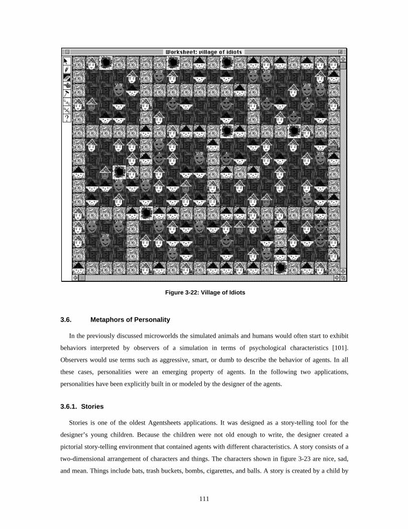
Figure 3-22: Village of Idiots
3.6. Metaphors of Personality
In the previously discussed microworlds the simulated animals and humans would often start to exhibit
behaviors interpreted by observers of a simulation in terms of psychological characteristics [101].
Observers would use terms such as aggressive, smart, or dumb to describe the behavior of agents. In all
these cases, personalities were an emerging property of agents. In the following two applications,
personalities have been explicitly built in or modeled by the designer of the agents.
3.6.1. Stories
Stories is one of the oldest Agentsheets applications. It was designed as a story-telling tool for the
designer’s young children. Because the children were not old enough to write, the designer created a
pictorial story-telling environment that contained agents with different characteristics. A story consists of a
two-dimensional arrangement of characters and things. The characters shown in figure 3-23 are nice, sad,
and mean. Things include bats, trash buckets, bombs, cigarettes, and balls. A story is created by a child by
111

drawing characters and things. Closeness of things to characters typically indicates ownership. For instance,
the mean guy (with the cigarette) owns the bat to the left of him.
A picture describes a state in the story. The state can be changed through the users by manipulating the
characters and things. Characters and things can react to change. Dragging the cigarette to the mean guy
will make the mean guy laugh (playing a laugh sound). Dragging the same cigarette to the bomb will lead
to a loud explosion (animation and sound).
Figure 3-23: The Story of the Nice, the Mean, and the Sad Guy
3.6.2. Maslow’s Village
A much more complicated application, called Maslow’s Village, was created by one of the designers of
the Village of Idiots. The inhabitants of Maslow’s village have a built-in model of personality based on
Maslow’s notion of the hierarchy of needs consisting of the needs for self-actualization, self esteem,
belongingness and love, safety, and physiological needs.
As soon as an agent has satisfied its needs on one level it can move on to the next higher level. The
needs determine the behavior of the agent. For instance, an agent having physiological needs, such as the
need for food, would go out and find some food. This need could be satisfied by picking up food at some
place that provides food in Maslow’s village. Ultimately, agents reaching the state of self-actualization
become more helpful to other agents, for instance, by giving them food.
3.7. Programming Metaphors
Programmable agents make use of graphical rewrite rules, explained in Section 2.6.2., to define the
behavior of agents. Although graphical rewrite rules are not specific to the following applications, the
applications have been driving the development of the graphical rewrite rules.
3.7.1. Programmable Idiots
An early version of the Village of Idiots is programmable idiots (Figure 3-24) in which idiots can move
on paths, go into houses, mate in houses, and have children.
112

Figure 3-24: Programmable Idiots
3.7.2. Turing Machine
The Turing Machine (Figure 3-25) has become a (possibly absurd) benchmark of programmability in the
visual programming community. In terms of a layered architecture, we end up with the level of abstraction
paradox: On top of Lisp we have Agensheets with AgenTalk. Based on that is the graphical rule system.
Finally, on top of the graphical rules we drop again onto the simplistic turing machine level of abstraction.
Figure 3-25: A Turing Machine Tape with Head
3.8. Metaphors of Evolution
I have discussed the definition of behavior of agents by programming them in AgenTalk, using the
graphical rewrite rules, programming by example, and programming by prompting. All these approaches
share the explicit interaction with the agent either by manipulating the agent itself (programming by
example, graphical rewrite rules) or by manipulating some textual representation of the behavior of the
agent (AgenTalk). A completely different approach is to define the behavior implicitly by breeding it.
The use of evolution allows the definition of behavior through evaluative knowledge instead of the more
demanding constructive knowledge. That is, instead of needing to know how to construct behavior, e.g., by
113

composing a program, users need only to be able to judge if one behavior is better suited for their tasks than
a different behavior. This evaluative knowledge is sufficient to drive the process of evolution.
Evolving agents map some set of possible perceptions to a set of possible reactions. This mapping
describes the behavior of the agent and is called the gene. Creatures with initial random genes are exposed
into some world. Users observe the behavior exhibited by different creatures with different random genes.
Then, users select a subset of creatures with promising behaviors. The genes of these promising creatures
are combined or mutated by the user in order to improve the behavior. Repeated applications of this process
lead to the evolution of the creature with the desired behavior.
It is important to note that the process of evalution involves only the selection of interesting behaviors
and not the construction of behavior using whatever mechanism. That is, the user does not need to be aware
of any encoding of behavior using any sort of notation, nor does the user need to manipulate the creature in
any way to instruct the creature.
Evolution requires only a minimal amount of information from the user, but it also poses some problems
as an implicit mechanism to define behavior. Evolution is intrinsically slow. If a user already has a very
clear understanding of the problem, then evolution may become a frustrating means toward the desired
ends. Furthermore, it is difficult to predict what kind of behaviors can be expected with a limited set of
perceptions and reactions.
3.8.1. Genetic Algorithm Lab
The Genetic Algorithm Lab contains simple creatures with behavior controlled by a gene. All creatures
live in a world consisting of patches containing food items. The creature’s perception is limited to its
immediate neighbors and the creature’s actions include the movement to one of the neighboring patches. If
the creature ends up on a patch containing food items, then the creature can eat one item. Otherwise the
creature can live off some reserve food items. Eventually, if the creature runs out of reserve food and ends
up on a patch with no food items, the creature dies. The number of perceive/react cycles the creature
experiences before it dies is an indication of the quality of the strategy used to survive.
114

Figure 3-26: The Crossing of Creatures
Users typically collect a number of promising creatures, The users usually judge creatures by the
number of cycles survived. In some cases, however, users select creatures with interesting behaviors such
as the exhibition of interesting patterns of food consumption. Then, users will operate on the promising
creature either by crossing pairs of creatures (Figure 3-26) or by slightly altering behavior through the
random change of the creature’s gene. Users will repeat these steps until their creatures are satisfactory.
115

3.8.2. Horse Race
A different world but using the same principles is the horse race application (Figure 3-27). The horse’s
perception is limited to obstacles in front of it. A “good” horse optimizes its energy to jump. That is, it
jumps high enough to avoid obstacles but not any higher because jumping high will cost time.
Figure 3-27: Horser
3.9. Metaphors of Containment
Agents can be used as containers of other containers (Figure 3-28). A simple example is the Finder
application which uses agents to reprint files, desk top patches, and trash buckets similar to the Macintosh
Finder. Folders are containers represented by hyperagents. Double clicking a folder agent will open another
agentsheet representing the contents of the folder.
Figure 3-28: The Agentsheets Desktop
3.10. Programming as Problem Solving
The previous sections have illustrated the versatility of the construction paradigm. Although the
descriptions focused on the role of metaphors as mediators, the descriptions also indicated indirectly how
the construction paradigm supported the perception of programming as problem solving and participatory
116

theater. This section stresses the perception of programming as problem solving by concentrating on one
particular application used to design phone voice dialogs [96, 111] (see Section 3.2.11).
The essence of programming as problem solving is the ability of representations to evolve. That is, a
construction paradigm should include mechanisms to incrementally create and modify spatial and temporal
representations. This stands in contrast to spatial representations used in more traditional visual
environments such as visual programming languages. BLOX Pascal [39], for example, makes use of two
types of built-in metaphors to simplify the task of programming. First, a jigsaw puzzle metaphor is used to
overcome syntactic difficulties of the Pascal programming language (Figure 3-29). Second, the metaphor of
control flow captures the semantics of BLOX Pascal. The point here is not to assess the usability of BLOX
Pascal but to simply point out that the spatial representation is fixed. In other words, the representation can
not be specialized toward the problem to be solved. The same holds true for other visual programming
languages that use distinct but nonetheless fixed metaphors. For instance, Fabrik [58] makes use of a data
flow metaphor, and ThingLab [8] uses constraints.
Figure 3-29: BLOX Pascal
The experience with Agentsheets indicates that the ability of spatial representations to evolve is crucial.
The first version of the Voice Dialog Environment was created in Spring 1991 (Figure 3-30). A simple
graph model consisting of nodes and arcs was used to deal with the syntactic aspect of voice dialogs. The
semantics were based on control flow. A node represented a state of the voice dialog. Arcs leaving the node
reflected options of phone keys that could be pressed by the user of a telephone to get to a new state. This
early representation was quite similar to the representation used by the voice dialog designers of US WEST
on paper.
117

Figure 3-30: Voice Dialog Design Environment, Spring 1991
Despite its simplicity the Spring 1991 version could already be used as “an object to think with” [86].
The designer of the Voice Dialog Design Environment exposed voice dialog designers very early on to the
prototype. The voice dialog designers, in turn, could play with the system and suggest improvements and
extensions to the representation.
The system evolved considerably during almost 3 years of development (Figure 3-31). In 1991, the
prototype was 40 lines of code long; by Fall 1993 it was 7000 lines. The syntactic metaphor of graph
models was replaced with the notion of a two-dimensional sequence and choice space (elaborated in
Appendix A). The semantic model of control flow was replaced with a combination of control and
information flow.
Rules of the Sequence/Choice Space:
• The Horizontal Rule: Design units placed physically adjacent to each other within a row are executed
from left-to-right.
• The Vertical Rule: Design units placed physically adjacent to each other within a column describe the
set of options or choices at that point in time in the execution sequence.
• The Arrow Rule: Arrows override all previous rules and define an execution ordering.
Figure 3-31: Voice Dialog Design Environment, Fall 1993
118

The Voice Dialog Design Environment is no longer a generic application that could be used reasonably
for radically different problem domains. The visual language for voice dialog design contains dozens of
primitives that are tailored to the problem domain. However, the problem solving-oriented construction
paradigm of Agentsheets simplified the process of finding a suited representation by (a) supporting the
creation of an early prototype that was used as a medium between designers and users, and by (b) assisting
the evolution of the representation with mechanisms to incrementally modify spatial and temporal
metaphors.
3.11. Participatory Theater
Participatory theater is used in Agentsheets applications to combine direct manipulation and delegation.
In the Kitchen Planner application (see Section 3.3.2.), users build kitchens consisting of appliances such as
sinks , refrigerators , and ovens . The autonomous behavior of appliance agents consists of
hill climbing. Each appliance tries to increase its happiness by either moving to a new location in the
kitchen or by rotating itself. Figure 3-32 shows a kitchen after dropping two sinks, one refrigerator, and one
stove into the kitchen. Two design guidelines shape the landscape of the problem space experienced by
each agent. First, the work triangle guideline suggests that the total distance between the refrigerator, the
stove, and the left sink should be less than 22 feet. Second, the two sinks should be right next to each other.
The kitchen depicted in Figure 3-34 is stable. That is, all appliances are happy and, therefore, not moving.
Figure 3-32: Initial Kitchen
The kitchen designer prefers to move the right sink into the upper right corner of the kitchen. However,
this causes a tension with the second design guideline that tries to keep the two sinks together.
119

Figure 3-33: Kitchen after Dragging Right Sink to Corner
On the basis of the relative strengths of the conflicting guidelines, the appliances move into new
positions in order to increase their happiness again. In this case both guidelines have equal strength. The
right sink bounces back two slots. At the same time, the left sink moves toward the right sink until they
meet again. The work triangle guideline indicates that the left sink, the refrigerator, and the stove are too far
apart. Consequentially, the stove will move toward the refrigerator and the left sink. The stove faces a
different wall and, in turn, has to rotate itself in order to face the new wall.
Figure 3-34: Work Triangle and Sink Adjacency are satisfied
As this example has illustrated, participatory theater can turn into a tactile experience of the design
space. Either approach in isolation, direct manipulation or delegation, would not convey the same amount
of information about the design space. The ability of the user to touch appliances and to see them react can
be the source of information that otherwise would be hard to acquire.
3.12. Conclusions and Implications
Metaphors are a very powerful way of thinking about problems. They help us to understand the new by
creating analogies to the old. In the case of construction paradigms used to create domain-oriented visual
dynamic environments, metaphors play the role of mediators. That is, they help us to create associations
between applications and construction paradigms.
120

We usually see the things we are looking for, and, furthermore, different people are looking for different
things; therefore, a general-purpose substrate should not be limited by a single type of representation in the
form of some metaphor hardwired into the substrate. Instead, substrates should be flexible to a point,
allowing users to design their own metaphors.
To engineer metaphors may be difficult, as their effectiveness depends on the experience and possibly
the cultural background of the metaphor user. However, substrates can suggest the design of metaphors by
providing evocative construction paradigms. The construction paradigm featured by Agentsheets, for
instance, is concerned not only with spatial metaphors but also with metaphors of time, communication,
human-computer (or human-metaphor) interaction, and with psychological metaphors.
121

CHAPTER 4CONCLUSIONS: AGENTSHEETS IS A SUBSTRATE FOR MANY DOMAINS
It is by logic that we prove, but by intuition that wediscover.
- Henri Poincaré
Overview
This chapter summarizes and relates the four major contributions revolving around the central theme of
this dissertation, which is the relationship among people, tools, and problems: (i) the construction paradigm
underlying the Agentsheets substrate, (ii) the perception of programming as problem solving, (iii) the view
of a continuous spectrum of control and effort called participatory theater, and (iv) the role of metaphors as
mediators between problem solving-oriented construction paradigms and domain-oriented applications.
Two extensions to the notion of catalogs are briefly discussed in the projections section. Catalogs should
be able to deal with multiple domains and should support the search for components based on temporal
features to help the user to find relevant causality instead of based on topology.
The implication section discusses how the four contributions effect a number of application domains and
research communities.
122

4.1. Contributions
This section discusses the four major contributions of Agentsheets, as presented in this dissertation,
which are concerned with the intricate relationships among people, tools, and problems. It is important to
note that these contributions are highly interwined. For each contribution, intuitions and support are
provided.
• Construction Paradigm: Agentsheets includes a versatile construction paradigm that is used for
building domain-oriented dynamic visual environments.
• Programming as Problem Solving: A construction paradigm should be problem-solving oriented rather
than domain-oriented. Agentsheets supports the exploratory nature of problem solving by providing
mechanisms to create and change spatial and temporal representations. Furthermore, the evolutionary
character of problem solving is supported with incremental mechanisms to define the behavior as well
as the look of representations consisting of agents.
• Participatory Theater: Participatory theater combines the advantages of human-computer interaction
schemes based on direction manipulation and delegation into a continuous spectrum of control and
effort.
• Metaphors as Mediators: Metaphors are mediators between domain-oriented applications and problem
solving-oriented construction paradigms. Furthermore, they support the reuse of applications by being
mediators between users. That is, communication in a community of users often takes places at the level
of metaphors rather than at the level of the construction paradigm or at the level of the concrete
application implementation.
Table 4-1 summarizes the relationships among the four issues discussed: construction paradigms,
programming as problem solving, participatory theater, and metaphors as mediators.
123
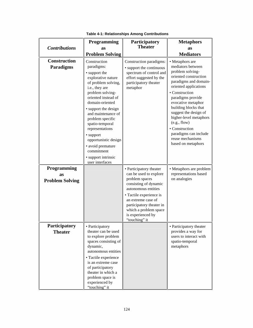
Table 4-1: Relationships Among Contributions
ContributionsProgramming
asProblem Solving
ParticipatoryTheater
Metaphorsas
MediatorsConstructionParadigms
Constructionparadigms:
• support theexplorative natureof problem solving,i.e., they areproblem solving-oriented instead ofdomain-oriented
• support the designand maintenance ofproblem specificspatio-temporalrepresentations
• supportopportunistic design
• avoid prematurecommitment
• support intrinsicuser interfaces
Construction paradigms:
• support the continuousspectrum of control andeffort suggested by theparticipatory theatermetaphor
• Metaphors aremediators betweenproblem solving-oriented constructionparadigms and domain-oriented applications
• Constructionparadigms provideevocative metaphorbuilding blocks thatsuggest the design ofhigher-level metaphors(e.g., flow)
• Constructionparadigms can includereuse mechanismsbased on metaphors
Programmingas
Problem Solving
• Participatory theatercan be used to exploreproblem spacesconsisting of dynamicautonomous entities
• Tactile experience isan extreme case ofparticipatory theater inwhich a problem spaceis experienced by“touching” it
• Metaphors are problemrepresentations basedon analogies
ParticipatoryTheater
• Participatorytheater can be usedto explore problemspaces consisting ofdynamic,autonomous entities
• Tactile experienceis an extreme caseof participatorytheater in which aproblem space isexperienced by“touching” it
• Participatory theaterprovides a way forusers to interact withspatio-temporalmetaphors
124

4.1.1. Construction Paradigms
A construction paradigm is the essence of a substrate used for building domain-oriented dynamic visual
environments. The degree of support provided to build environments depends on two contending forces. On
the one hand, support increases with increased domain-orientation of the tool by reducing the
transformation distance between problem domain and tool [29]. On the other hand, a high degree of
domain-orientation can limit the versatility of a tool. That is, a highly specialized tool may be useful for
only a relatively small domain. The challenge for a construction paradigm is to provide maximum leverage
to build environments without sacrificing its applicability to a large range of problem domains.
The Agentsheets construction paradigm is versatile in that it supports the creation of environments in
many different domains and at the same time provides a high degree of leverage by being problem-solving
oriented rather than domain-oriented. That is, the substrate supports the exploratory nature of problem
solving, the design and the maintenance of problem-specific spatio-temporal representations, and
opportunistic design [46]. These principles hold true for a large number of domains. All of these points are
elaborated in the next section on programming as problem solving.
A different challenge posed to the Agentsheets construction paradigm arises from the dynamic nature of
many of the application domains anticipated. A construction paradigm has to include interaction schemes
that give users the desired degree of control and effort over applications that consists of a large number of
autonomous units. To that end, Agentsheets supports the participatory theater metaphor.
Agentsheets contains a versatile, problem solving-oriented construction paradigm forbuilding domain-oriented dynamic visual environments.
The claim that Agentsheets contains a versatile construction paradigm is supported with more than 40
applications that have been built using Agentsheets (some are described in Chapter 3). Subjects have
created these Agentsheets applications as part of their Ph.D. research, for their jobs, and as class projects.
The construction paradigm can be used to create applications for a wide range of domains.
The applications listed below support this point. Most of them are explained in Chapter 3.
• Artificial Life Environments: EcoAlaska, EcoOcean, EcoSwamp, Village of Idiots, Maslow’s Village
• Board Games: Othello, PackAgents, Mines (an Agentsheets version of the mine game)
• Complex Cellular Automata: Segregation
• Design Environments: Networks
• Genetic Algorithms: Genetic Algorithm Lab, Horse Race
• Geographical Information Systems (GIS): Tax The Farmer, Reservoir Modeling
125

• Iconic Spreadsheet Extensions: Interactors (a spreadsheet extension adding special interaction methods:
cells can move themselves, cells can react to mouse clicks)
• Programmable Drawing Tools: AgentPaint (a simple Agentsheets version of the SchemePaint
environment [23], Stories
• Simulation Environments: Particles, Electric World, City Traffic, Channels
• Soft Constraints : Party Planner, Kitchen Planner
• Visual Programming Languages: VDDE, VisualKEN, Petri Nets, LabSheets
The construction paradigm provides an intrinsic user interface.
The notion of intrinsic user interfaces is anchored in the construction paradigm by means of the agents
in a grid paradigm. Every agent is visible in some worksheet and can be manipulated by a set of tools, by
the mouse, and via the keyboard. A new agent subclass created by the user will inherit all the methods to
visualize itself and to interact with the user. The user can specialize the visualization of agents as well as
the interaction protocol. Furthermore, the agents in Agentsheets are not considered mediators between the
user and the application; instead, they are the application. That is, the construction paradigm is not used to
create user interfaces but to create entire applications including user interfaces.
The construction paradigm allows opportunistic design and avoids prematurecommitment.
The construction paradigm of Agentsheets does not rely on any “proper” sequence of operations,
resulting from design strategies such as top down. Users can define the look and the behavior of agents in
any sequence they like. In fact, behavior and look can be defined separately and linked with each other at
any point in time. Most designs of new systems started by using Agentsheets as a drawing package. That is,
a number of agents were quickly sketched and put into a worksheet. The behavior of these agents is
defined, by default, by the most general agent class. Designers explained to each other their perceptions of
the design by moving the agents around using the mouse and by applying tools to agents. Even in an early
stage of design like this, Agentsheets helped them to convey their ideas: “..if a blah is on the left of a bloh
and I double-click the bloh then the blah would do this and this.” With increasing consensus, designers
would add methods to agents in order to formalize their intuitions of behavior.
The ability to specify look and behavior in any order as well as the support to refine both look and
behavior incrementally helps to avoid premature commitment [46]. This encourages the creation of early
design prototypes because the anticipated overhead is very low.
126

4.1.2. Programming as Problem Solving
I endorse the view of programming environments as problem solving vehicles. The more traditional
view of programming environments as implementation facilitating devices assumes that a problem is
sufficiently well understood that the process of programming is a mapping of the problem understanding
onto a programming mechanism [47]. However, adopting the “programming as problem solving” view
leads to a programming substrate of a different nature, which focuses on facilitating the problem-solving
process rather than as an “implementation as mapping” process.
One important implication resulting from viewing programming as problem solving is that an
underlying substrate should support the creation and maintenance of spatial representations suitable to
problems. Simon [105] points out that the process of problem solving not only includes creating
representations but the changing representations until a solution becomes visible. Unlike typical visual
programming languages, which are often limited to a single, hard-wired spatial representation such as data
or control flow, the construction paradigm featured in Agentsheets can be used to create a wide spectrum of
spatial representations consisting of implicit and explicit notations (see Chapter 1).
Agentsheets supports the creation of spatial representations:
Implicit spatial representations (based on topological spatial relationships between agents such as
adjacency) and explicit spatial representations (based on links between agents) have been heavily employed
by users. Effect, Effect-Absolute, Effect-Link, and Effect-Sheet are all spatial communication mechanisms
that were used to create spatial representations.
Agentsheets supports the creation of temporal representations:
In the majority of the applications the notion of time was crucial. For instance, many applications (e.g.,
Electric World) made use of the flow metaphor.
Agentsheets supports the incremental specialization of behavior and look ofrepresentations.
All the task-specific Agentsheets tools, such as the icon editor, gallery, and color palette, were created
by specializing generic agent and agentsheet classes. All classes created in all applications were subclasses
of agents. That is, they introduced new kinds of agents by specializing the behavior of agents. Again, all
applications made use of cloning, which is the mechanism to specialize the look of agents.
127

4.1.3. Participatory Theater
Spatio-temporal representations require sophisticated human-computer interaction schemes, especially
when they are used to control a large number of autonomous units. Participatory theater combines the
advantages of human-computer interaction schemes based on direction manipulation and delegation into a
continuous spectrum of control and effort.
Participatory theater can be used to explore problem spaces consisting of dynamic,autonomous entities.
For most problems the ability to create and change representations is not sufficient. There is the
additional need to interact with the representation. This becomes especially challenging if the
representation consists of autonomous entities. In the case of the Kitchen Planner (Chapter 3) participatory
theater combines the advantages of being able to directly manipulate kitchen appliances with the ability of
kitchen appliances to autonomously optimize their location in the kitchen through the use of hill climbing.
Either approach by itself is limited. Direct manipulation, although it provides users with maximum control
over the process of design, gives users very little guidance to design artifacts. Hill climbing, on the other
hand, is a way to delegate, at least partially, the problem-solving process to agents. Without participatory
theater, users, while minimizing their effort, can lose certain aspects of control over the problem-solving
process. The use of autonomous problem-solving mechanisms, such as hill climbing, can lead to solutions
that appear to be optimal in terms of design principles but are unsatisfactory in the light of subjective
evaluation by users. Participatory theater synergetically combines the advantages of direct manipulation
and delegation into a new scheme of interaction that exceeds the possibilities of either constituent. For
instance, direct manipulation can be used to direct agents participating in hill climbing to get out of local
maxima.
Tactile experience is an extreme case of participatory theater in which a problem space isexperienced by “touching” it.
Tactile experience is a situation in which a user gets access to additional knowledge about a problem
space by touching the agents. For instance, agents engaged in a hill climbing process, such as the Kitchen
Planner and the Party Planner, can end up in a state of equilibrium for many different reasons. The
participation of the user in the form of touching these agents can reveal information such as the stability of
the equilibrium. An environment exclusively based on either direct manipulation or delegation would
require the additional mechanisms to convey this kind of information to the user. In the case of the Kitchen
Planner, for instance, spatial concepts such as the working triangle can be tactically experienced by moving
appliances such as stoves, refrigerators, and sinks.
128

Participatory theater provides a way for users to interact with spatio-temporal metaphors.
Dictated by the notion of participatory theater, Agentsheets provides mechanisms for users to interact
with agents that are engaged in autonomous actions. In the participatory theater users and agents can both
take the initiative at the same time to do things that are potentially conflicting. The construction paradigm
featured in Agentsheets includes resolution strategies to deal with conflicting initiatives.
4.1.4. Metaphors as Mediators
In many problem domains, representations deal with the abstract concepts through the use of analogies
to concrete things. That is, in many cases representations are metaphors that help us to cope with the
unknown by relating it to the known.
Metaphors play the role of mediators. In the domain of natural language, metaphors are mediators
between the infinite number of sentences that can be formulated from a large vocabulary of words. The
view of natural language as tools, suggested by Zipf [118], includes the analogies of words to tools and
sentences to artifacts. That is, we communicate with each other by applying the right words to built
sentences like we apply tools to create artifacts. In both domains metaphors are the mediators that simplify
the mapping between two very large sets of entities. In one case they are mediators between words and
sentences, in the other case between artifacts and tools.
The mediation process entails representation and implementation. In Agentsheets, metaphors are used to
represent application semantics by helping people to conceptualize problems in terms of concrete
metaphors. On the other hand, metaphors can simplify the implementation of applications. Application
designers can explore and reuse existing applications that include similar metaphors.
Metaphors are Mediators between Users.
Communication between people typically happens on the level of metaphors and not on the level of
either the construction paradigm or the application level. The application level, on the one hand, is
concerned with the definition of behavior and of appearance specific to problem domains. Methods featured
in the construction paradigm, on the other hand, are generic. Metaphors exhibit principles that can be
reused in a wide range of domains, but at the same time provide a high level of abstraction to be used as
representations.
The similarity measure (explained in Appendix A) can reveal relationships between applications on the
metaphor level. Similarity compares pairs of applications with respect to their use of spatial and non-spatial
communication between agents. For instance, Maslow’s Village is an Agentsheets application that was
created by one person previously involved in the Village of Idiots design team. Despite the fact that both
129

applications share only common superclasses that are part of the Agentsheets construction paradigm, and
the fact the one application is about twice as large as the other (2500 lines of code versus 1100 lines of
code), similarity returns a perfect match between the two applications reflecting design correlation.
Application similarity suggests that the transfer between applications is based on metaphor reuse. In
other words, people start new applications by copying code from old applications, providing related
behavior. This finding is compatible with Lange’s observation of programmers [66] using object-oriented
environments borrowing source code . For instance, the mechanism of propagating water in the channel
application (see Chapter 3) helped a different person to create a mechanisms to deal with electric signals in
the Rocky’s Other Boot application.
In reusing code from other people, typical users of object-oriented approaches rarely factor out code by
creating common superclasses. One reason is that the introduction of superclasses to other people’s class
hierarchies can have unexpected side effects. Instead, they copy and paste relevant code and modify it.
These types of transfers are difficult to trace with traditional object-oriented programming metrics that are
based on class hierarchies. However, metrics, like application similarity, that are indicative for what code is
doing rather than where in the class hierarchy it is located, can reveal these relationships even after
extensive modifications of the code.
Metaphors are Mediators between Problem Solving-Oriented Construction Paradigms andDomain-Oriented Applications.
As indicated in Chapter 3, a large number of applications share metaphors. For instance, the City Traffic
application and Rocky’s Other Boot share the metaphor of flow. In City Traffic the flowing substances
consists of cars moving on roads, while in Rocky’s Other Boot the flowing substances is the electrical
signals traveling through wires. The question is whether metaphors are simply a emerging characteristics of
applications or whether they can be used in constructive ways to create new applications.
Metaphors have been criticized for being too generic and not powerful enough to reflect problem
domain specific semantics. Nardi [84] argues that metaphors do not promise a rich set of reusable
application objects that support the development of specialized applications. She acknowledges the
usefulness of metaphors to provide a general orientation but is skeptic about how accurately metaphors can
provide precise semantics. I believe that the role of metaphors in providing a general orientation is crucial,
and that Agentsheets furnishes evocative mechanisms to create metaphors specialized to problem domains.
In short, I agree with Nardi’s point that metaphors should be specializable, but I believe that the
specialization problem is not intrinsic to the notion of metaphors and can be addressed in computational
media.
130
The design process for most Agentsheets applications consists of a metaphor creation phase and a
metaphor specialization phase. In applications the Voice Dialog Design Environment, early design
activities were concerned with finding suitable spatial problem representation. The 1991 design consisted
of a simple graph model. Nardi is correct in saying that visual formalisms, such as graphs or tables, are not
metaphors by themselves. That is, a graph is not an analogy to a concrete situation about which many
people would be aware. However, the ways these visual formalisms are used are often guided by
metaphors. For instance, the graph model used in the VDDE is based on the metaphor of (control) flow.
The same substrate, Agentsheets, also supports the metaphor specialization phase. In the last two years,
VDDE has grown from significantly. The metaphor of flow provided an essential guideline for the
semantics of the primitives added to the environment specific to the task of designing voice dialogs.
To use metaphors in constructive ways is problematic because people are often unaware of their use of
metaphors. Blumenthal [7] has created a metaphor construction kit, called MAID, consisting of a library of
reusable metaphors, that supports the creation of user interfaces. This approach can lead to two types of
problems. First, people often seem to be unaware of what metaphors they use. Second, as Nardi points out,
it is difficult to express application domain-specific semantics with these systems. Agentsheets takes a
different approach to suggest metaphors. Instead of providing a library of high-level metaphors that can be
selected by a user, Agentsheets provides an evocative construction paradigm to build new high-level
metaphors. The notion of autonomous agents sharing a space is useful to create metaphors of space, time,
communications, and interaction. Furthermore, the metaphors created can be specialized by designers
toward specific problem domains.,
131

4.1.5. Summary
Table 4-2 summarizes and supports the four contributions of this dissertation.
Table 4-2: Contributions, Support and Intuition
Contribution Supported byConstruction Paradigm
A versatile construction paradigm to builddynamic visual environments for manydifferent problem domains
• 40 applications (between 30 and 6000 lines of code)built in many different domains by different users
Programming as Problem Solving
Mechanisms to incrementally create andchange spatial and temporalrepresentations
• creation and evolution of the Voice Dialog DesignEnvironment
• the evolution from the Village of Idiots applicationto the Maslow’s Village application
Participatory Theater
Combines the advantages of human-computer interaction schemes based ondirection manipulation and delegation intoa continuous spectrum of control andeffort
• interaction between user and creatures inEcoSwamp, EcoAlaska, and EcoOcean
• traffic control in City Traffic
• interaction with kitchen appliances in KitchenPlanner
Metaphors as Mediators
Metaphors are mediators between:
• domain-oriented applications and problemsolving-oriented construction paradigms
• users
• applications share metaphors (e.g., flow)
• designers reuse other applications on a metaphorlevel
4.2. Projections
This section briefly outlines possible extensions to the framework and raises additional questions related
to the proposed principles. Two possible extensions are related to Fischer’s notion of catalogs [28]. The
measure of similarity between applications (defined in Appendix A), could be used as an active search tool
to explore the space of either similar or dissimilar applications. Dynamic environments pose new problems
that are not addressed with static search tools. The second extension proposes the use of the theory for the
view of causality as a means to search for dynamic attributes.
Fischer stresses the importance of catalogs to navigate through the space of past problems and solutions.
Fischer’s notion of catalogs can be generalized along two dimensions:
• Multiple Domains: In Fischer’s work, catalogs are only concerned with single domains (e.g., kitchen
design). Agentsheets applications come from a wide range of domains.
132

• Dynamic Domains: The design components in Fischer’s domains are static. That is, they are not
associated with autonomous behavior. Agentsheets, on the other hand, deals with autonomously
behaving units.
Agentsheets envisions a large number of domains, and many of these domains include active objects.
How can a catalog support inter-domain search tasks and how can a catalog support the search of dynamic
features in a domain?
4.2.1. Catalogs for Dynamic Domains: Causality Finder
Search mechanisms for dynamic systems should include ways to find dynamic information. Direct
manipulation interfaces such as the Macintosh Finder or WYSIWYG-type document editors include search
mechanisms based on the hand puppet metaphor. Since the behavior of the hand puppets is dictated by the
user who operates them, search mechanisms have to be limited to finding topological information such as a
file in some folder or a string of characters in some document. However, in user interfaces that include
proactive human interaction schemes, such as the participatory theater, it would be desirable to have a
mechanisms to search for properties arising from the dynamics of the system such as causality.
Spatio-temporal metaphors, such as the participatory theater, have the capability to imply causality.
Unlike strictly spatial metaphors, spatio-temporal metaphors can make people actually experience causality.
Michotte has shown that people directly perceive causality of events [74]. He has found that the impression
of causality is dependent on specific and narrowly limited spatio-temporal features of the event observed.
For instance, we do not see one billiard ball cause another one to move because we intuitively apprehend a
fact of nature, nor because of past experiences leading us to such conclusions. Instead, we directly perceive
the causality of one billiard ball launching another one because of the spatio-temporal organization of that
kinetic event. Michotte has classified a fundamental set of effects leading to perception of causality
including: launching effect, entraining effect, withdrawal effect, and tunnel effect.
At the time of these findings, 1946, Michotte's experiments consisted of people observing contours
painted on revolving discs, causing the illusion of moving objects when observed through a slit. Today, we
can use animated computer graphics and make use of the effects identified by Michotte to imply causality
in many different domains through a metaphorical mapping. I believe that these relatively old theories are
of fundamental importance for computer programming because they allow us to go beyond current
paradigms of programming that are limited by their definition of semantics in terms of static, topological
characteristics (e.g., syntax).
Topology and causality are highly related. In many cases we can make inferences from one to the other.
For instance, in the domain of computer networks, an important topological attribute of a network is the
133

termination of an end with a terminator. Electric signals traveling on a net and reaching a non-terminated
end will bounce, i.e., the signal will get reflected back. If we know that a terminator is missing (topological
information) we can infer that bouncing will take place (information regarding causality). On the other
hand, if we experience the bouncing of a signal we could infer the lack of a terminator.
Today we have many tools and mechanisms to search for topology but no mechanisms to search for
causality. Topology tools such as the Macintosh Find File command or the find string commands in most
text editors are adequate to search for static relationships but unsatisfactory to find certain causalities. In the
network domain, if we want to find a bouncing signal (causality) then we do not like to search for an
according topology that we hope implies that causality. Ideally, we would have a causality search
mechanism that allows us to search for the bouncing signal directly. Michotte's theory can be used not only
to explain how people perceive causality, but also to build mechanisms, e.g., agents, that can perceive
causality for us. This, effectively, would make these mechanisms suitable to search causality.
In our network application we have built in a first version of a very simple agent able to perceive a
subset of the Michotte perception of causality effects. That agent can be given the task to find, for instance,
a network with bouncing network packets. The agent will run existing networks, created earlier by a
designer, for a while and notify the user of events perceived as bouncing.
4.2.2. Catalogs for Multiple Domains: Similar Behavior Finder
The similarity measure (see Appendix A) to compare different Agentsheets applications could be used
not just as an analytical part of this dissertation but, additionally, it could be built in to the Agentsheets
environment, or related systems, as a search tool to find similar applications.
In a typical use scenario of Agentsheets, users will “play” with individual applications. Depending on
the user’s interest in the application under investigation, the user could formulate two kinds of queries:
• Find all other applications that are very similar: The system would determine the similarity between
the current application and all other applications. A sorted list of applications with decreasing similarity
would be returned to the user.
• Find all other applications that are very dissimilar: The system would determine the similarity between
the current application and all other applications. A sorted list of applications with increasing similarity
would be returned to the user.
On the one hand, this kind of behavior search tool could help users to identify other similar applications
that, for instance, share related metaphors or have been created by overlapping teams. On the other hand,
users can quickly move on to radically different applications if they dislike some application or if they are
interested in getting a good overview of the variety of applications available.
134

4.3. Conclusions and Implications
There are four contributions of Agentsheets as a substrate presented by this dissertation. These
constributions are problem-oriented construction paradigms, programming as problem solving,
participatory theater, and metaphors as mediators. They contain unifying principles for different domains
and research communities such as the visual programming, simulation, distributed artificial intelligence,
object-oriented programming, human-computer interaction, art, and environmental design. The point of this
dissertation is not to propose portentous extensions to individual domains and research communities in the
traditional sense. What is unique about Agentsheets is the large variety of applications that can be built to
solve very different problems by very different users utilizing one unifying substrate.
The same could be said about general purpose programming languages such as “C”. “C” has established
itself in a large number of domains and research communities. However “C”, unlike Agentsheets, does not
provide a construction paradigm that supports the explorative nature of problem solving, nor does it provide
any simple mechanisms to design spatial and temporal metaphors. All these attributes can be added to the
language in the form of libraries. Yet, this is not the point. Mechanisms that support programming as
problem solving, participatory theater, and metaphors as mediators should not be add-ons to programming
languages. Instead, they should be the driving forces of design making computers more useful and usable.
Agentsheets means different things to different people. Users, when asked what they like about
Agentsheets, usually reply very differently depending on their backgrounds. People in environmental
design looked at Agentsheets as an interesting extension of Geographical Information Systems (GIS) that
adds the notion of dynamics and a means to simulate the fundamental relationship between the physical
environment and behavior [3]. To the visual programming community, Agentsheets is a tool kit to create
visual programming languages that are tailored to specific problem domains. The education community
views Agentsheets as an extension of *Logo with “fancy representations” that allows users not only to
program the but also to interact with individual entities. To the object-orientation community, Agentsheets
is a concurrent extension with an intrinsic user interface of the object-oriented paradigm. To the simulation
society, Agentsheets provides an interesting combination of direct manipulation and delegation. Within the
distributed artificial intelligence community, Agentsheets can be used as a test bed to experiment with
different types of interactions among heterogeneous agents. The human-computer interaction community
finds that Agentsheets makes different use of agents in the sense that agents are not interface mediators
between user and applications but they are the applications. Finally, to the art community, Agentsheets is a
simple drawing tool with a living canvas that becomes an active entity capable of reacting to the user as
well as capable of initiating actions autonomously.
I do not by any means wish to suggest that Agentsheets is a universal solution for all these domains and
research communities. For example, the strong discretizing of space through the grid, makes Agentsheets
135

the wrong tool for many problems. However, such limitations are not necessarily intrinsic to problem
domains. Instead, they often arise from the ways we conceptualize problems. I suspect that the overlap
between problem domains and communities is much larger than generally acknowledged. Agentsheets is
not just a drawing program, or a simulation environment, artificial life tool, visual programming
construction paradigm, or object-oriented programming approach. On the one hand, it is a substrate
supporting the commonalties in these domains and, on the other hand, it is a new way to think about the
intricate relationships among people, tools, and problems. In short, construction paradigms, the perception
of programming as problem-solving, participatory theater as a human-computer interaction scheme, and
metaphors as mediators should not just be understood with respect to their technical implications. Instead,
they should also be viewed as different ways to interact with and to perceive computers moving even
further away from their historic image of number crunching devices. My hope is that the principles
discovered in this work will serve to bring together these seemingly diverse communities.
136

REFERENCES
1. Adams, S. T. and A. A. DiSessa, “Learning by Cheating: Students Inventive Ways of Using aBoxer Motion Microworld,” Journal of Mathematical Behavior, pp. 79-89, 1991.
2. Arnheim, R., Visual Thinking, University of California Press, Berkeley, 1969.
3. Barker, R., Ecological Psychology: Concepts and Methods for Studying Human Behavior, StanfordUniversity Press, Stanford, CA, 1968.
4. Bell, B., “ChemTrains: A Visual Programming Language for Building Simulations,” TechnicalReport, CU-CS-529-91, Department of Computer Science, University of Colorado at Boulder, CO,1991.
5. Bell, B., “Using Programming Walkthroughs to Design a Visual Language,” University ofColorado at Boulder, Ph.D. dissertation, Dept. of Computer Science, 175 Pages, 1992.
6. Bell, B., J. Rieman and C. Lewis, “Usability Testing of a Graphical Programming System: ThingsWe Missed in a Programming Walkthrough,” Proceedings CHI’91, New Orleans, Louisiana, 1991,pp. 7-12.
7. Blumenthal, B., “Strategies for Automatically Incorporating Metaphoric Attributes in InterfaceDesign,” Proceedings of the ACM SIGGRAPH Symposium on User Interface Software andTechnology, 1990, pp. 66-75.
8. Borning, A., “Defining Constraints Graphically,” CHI86, 1986, pp. 137-143.
9. Bouron, T., J. Ferber and F. Samuel, “MAGES: A Multi-Agent Testbed for HeterogeneousAgents,” Decentralized A.I. 2, Saint-Quentin en Yvelines, France, 1991, pp. 195-214.
10. Brachman, R. J., “I Lied about the Trees Or, Defaults and Definitions in the KnowledgeRepresentation,” The AI Magazine, pp. 80-93, 1985.
11. Brooks Jr., F. P., “No Silver Bullet: Essence and Accidents of Software Engineering,” IEEEComputer, pp. 10-19, 1987.
12. Cattaneo, G., A. Guercio, S. Levialdi and G. Tortora, “ICONLISP: An Example of a VisualProgramming Language” IEEE Computer Society, Workshop on Visual Languages, Dallas, 1986,pp. 22-25.
13. Chapman, D., “Vision Instruction and Action,” The MIT Press, Cambridge, MA, 1991.
14. Cox, B. and B. Hunt, “Objects, Icons, and Software-ICs,” BYTE, Vol. August, pp. 161-176, 1986.
15. Cox, B. J., “There Is a Silver Bullet,” Byte, pp. 209-218, 1990.
16. Cypher, A., “Watch What I Do: Programming by Demonstration,” MIT Press, Boston, 1993.
17. Dewdney, A. K., “The Magic Machine,” W. H. Freeman and Company, New York, 1990.
18. Dijkstra, E., “On the Cruelty of Really Teaching Computer Science,” Communications of the ACM,pp. 1397-1404, 1989.
137

19. diSessa, A. A., “A Principled Design for an Integrated Computational Environment,” Human-Computer Interaction, Vol. 1, pp. 1-47, 1985.
20. diSessa, A. A., “An Overview of Boxer,” Journal of Mathematical Behavior, pp. 3-15, 1991.
21. diSessa, A. A., D. Hammer and B. Sherin, “Inventing Graphing: Meta-Representational Expertisein Children,” Journal of Mathematical Behavior , pp. 117-160, 1991.
22. Douglas, S., E. Doerry and D. Novik, “QUICK: A User-Interface Design Kit for Non-Programmers,” Proceedings of the ACM SIGGRAPH Symposium on User Interface Software andTechnology, Snowbird, Utah, 1990, pp. 47-56.
23. Eisenberg, M., “Programmable Applications: Interpreter Meets Interface,” A.I. Memo, 1325, MIT,1991.
24. Fenton, J. and K. Beck, “Playground: An Object-Oriented Simulation System with Agent Rules forChildren of All Ages,” OOPSLA 89, New Orleans, Louisiana, 1989, pp. 123-137.
25. Fikes, R. and T. Kehler, “The Role of Frame-Based Representation in Reasoning,”Communications of the ACM, Vol. 28, pp. 904-920, 1985.
26. Finzer, W. and L. Gould, “Programming by Rehearsal,” Byte, Vol. 9, pp. 187-210, 1984.
27. Fischer, G., “Making Computers more Useful and more Usable,” 2nd International Conference onHuman-Computer Interaction, Honolulu, Hawaii, 1987.
28. Fischer, G., “Domain-Oriented Design Environments,” Automated Software Engineering, 1993.
29. Fischer, G. and A. Girgenson, “End-User Modifiability in Design Environments,” CHI ‘90,Conference on Human Factors in Computing Systems, Seattle, WA, 1990, pp. 183-191.
30. Fischer, G., A. Lemke, T. Mastaglio and A. Morch, “Using Critics to Empower Users,” CHI ‘90 ,Seattle, WA, 1990, pp. 337-347.
31. Fischer, G. and A. C. Lemke, “Construction Kits and Design Environments: Steps Toward HumanProblem-Domain Communication,” HCI, Vol. 3, pp. 179-222, 1988.
32. Fischer, G., A. C. Lemke, T. Mastaglio and A. Morch, “The Role of Critiquing in CooperativeProblem Solving,” ACM Transactions on Information Systems, Vol. 9, pp. 123-151, 1991.
33. Fischer, G. and C. Rathke, “Knowledge-Based Spreadsheets,” 7th National Conference onArtificial Intelligence, St. Paul, MI, 1988, pp. 1-10.
34. Foley, J. J., V. L. Wallace and P. Chan, “The Human Factors of Computer Graphics InteractionTechniques,” IEEE, pp. 13-48, 1984.
35. Ford, G. A. and R. S. Wiener, Modula-2, A Software Development Approach, John Wiley & Sons,New York, 1985.
36. Funt, B., V., “Problem-Solving with Diagramatic Representations,” Artificial Intelligence, Vol. 13,pp. 201-230, 1980.
37. Furnas, G. W., “New Graphical Reasoning Models for Understanding Graphical Interfaces,”Proceedings CHI’91, New Orleans, Louisiana, 1991, pp. 71-78.
38. Gardin, F. and B. Meltzer, “Analogical Representations of Naive Physics,” Artificial Intelligence,Vol. 38, pp. 139-159, 1989.
138

39. Glinert, E. P., “Towards “Second Generation” Interactive, Graphical Programming Environments,”IEEE Computer Society, Workshop on Visual Languages, Dallas, 1986, pp. 61-70.
40. Glinert, E. P., M. M. Blattner and C. J. Freking, “Visual Tools and Languages: Directions for the‘90s,” 1991 IEEE Workshop on Visual Languages, Kobe, Japan, 1991, pp. 89-95.
41. Glinert, E. P. and S. L. Tanimoto, “Pict: An Interactive Graphical Programming Environment,”IEEE Computer, pp. 265-283, 1984.
42. Gold, R., The Village of Idiots, Personal Communication, 1991
43. Goldberg, A., “Smalltalk-80: The Interactive Programming Environment,” Addison-Wesley,Reading, MA, 1983.
44. Goldberg, A. and D. Robson, “Smalltalk-80: The Language,” Addison-Wesley, Reading, MA,1989.
45. Golin, E. J., “Tool Review: Prograph 2.0 from TGS Systems,” Journal of Visual Languages andComputing, pp. 189-194, 1991.
46. Green, T. R. G., “Cognitive Dimensions of Notations,” Proceedings of the Fifth Conference of theBritish Computer Society, Nottingham, 1989, pp. 443-460.
47. Green, T. R. G., “Programming Languages as Information Structures,” in Psychology ofProgramming, J. M. Hoc, T. R. G. Green, R. Samurcay and D. J. Gilmore, Eds., Academic Press,San Diego, 1990, pp. 117-137.
48. Green, T. R. G., M. Petre and R. K. E. Bellamy, “Comprehensibility of Visual and TextualPrograms: A Test of Superlativism Against the ‘Match-Mismatch’ Conjecture,” Empirical Studiesof Programmers: Fourth Workshop, New Brunswick, NJ, 1991, pp. 121-146.
49. Guttag, J. V., “Why Programming is Too Hard and What to Do About It,” in Research Directionsin Computer Science: An MIT Perspective, A. Meyer, J. Guttag, R. L. Rivest and P. Szolovits, Eds.,MIT Press, Cambridge, MA, 1991, pp. 9-28.
50. Harstad, B., “New Approaches for Critiquing Systems: Pluralistic Critiquing, ConsistencyCritiquing, and Multiple Intervention Strategies,” University of Colorado at Boulder, M.S. Thesis,Dept. of Computer Science, 93 pages, 1993.
51. Hart, R. A. and G. T. Moore, “The Development of Spatial Cognition: A Review,” in Image andEnvironment, R. M. Downs and D. Stea, Eds., Aldine Publishing Company, Chicago, 1973, pp.246-288.
52. Hayes, J. P., “The Logic of Frames,” in Frame Conceptions and Text Understanding, M. D., Ed.,Walter de Gruyter and Co., Berlin, 1979, pp. 46-61.
53. Hils, D. D., “Visual Languages and Computing Survey: Data Flow Visual ProgrammingLanguages,” Journal of Visual Languages and Computing, pp. 69-101, 1992.
54. Horn , R., E., “The Guide to Simulations/Games for Education and Training,” Didactic Systems,Inc., Cranford, 1977.
55. Hudson, S. E., “An Enhanced Spreadsheet Model for User Interface Specification,” TechnicalReport, TR 90-33, University of Arizona, Department of Computer Science, Tucson, AZ, 1990.
139

56. Hutchins, E. L. ,“The Technology of Team Navigation,” in Intellectual Teamwork: Social andTechnological Foundations of Coorperative Work, J. Galegher, R. E. Kraut and C. Egido, Ed.,Lawrence Erlbaum Associates, Hillsdale, NJ, 1990, pp. 191-220.
57. Hutchins, E. L., J. Hollan D. and D. Norman A., “Direct Manipulation Interfaces,” in UserCentered System Design, D. Norman A. and S. Draper W, Eds., Lawrence Erlbaum Associates,Hillsdale, NJ, 1986, pp. 87-124.
58. Ingalls, D., S. Wallace, Y.-Y. Chow, F. Ludolph and K. Doyle, “Fabrik: A Visual ProgrammingEnvironment,” OOPSLA ‘88, San Diego, CA, 1988, pp. 176-190.
59. Jefferson, D., R. Collins, C. Cooper, M. Dyer, M. Flowers, R. Korf, C. Taylor and A. Wang,“Evolution as a Theme is Artificial Life: The Genesys/Tracker System,” Tech. Report, UCLA-AI-90-09, Artificial Intelligence Laboratory, Computer Science Department, University of California,Los Angeles, CA, 1990.
60. Johnson, J., B. A. Nardi, C. L. Zarmer and J. Miller, “ACE: Building Interactive GraphicalApplications,” Communications of the ACM, Vol. 36, pp. 40-55, 1993.
61. Johnson-Laird, P. N., The Computer and the Mind, Harvard University Press, Cambridge, 1988.
62. Kopache, M. E. and E. P. Glinert, “C2: A Mixed Textual/Graphical Environment for C,” IEEEProceedings on Visual Languages, 1988, pp. 231-238.
63. Lai, K.-Y., W. M. Malone and K.-C. Yu, “Object Lens: A “Spreadsheet” for Cooporative Work,”ACM, Vol. 6, pp. 332-353, 1989.
64. Lakeoff, G. and M. Johnson, Metaphors We Live By, The University of Chicago Press, Chicago andLondon, 1980.
65. Lampson, B. W. and D. D. Redell, “Experience with Processes and Monitors in Mesa,”Communications of the ACM, Vol. 23, pp. 105-117, 1980.
66. Lange, B. M., “Some Strategies of Reuse in an Object-Oriented Programming Environment,”CHI’89, Huston / Texas, 1989, pp. 69-73.
67. Larkin, J. H. and H. A. Simon, “Why a Diagram is (Sometimes) Worth Ten Thousand Words,”Cognitive Science, Vol. 11, pp. 65-99, 1987.
68. Lewis, C., “NoPumpG: Creating Interactive Graphics with Spreadsheet Machinery:,” TechnicalReport, CU-CS-372-87, Department of Computer Science, University of Colorado at Boulder,Boulder, Colorado, 1987.
69. Lewis, C. and G. M. Olson, “Can Principles of Cognition Lower the Barriers to Programming?,”Empirical Studies of Programmers: Second Workshop, Norwood, NJ, 1987, pp. 248-263.
70. Lewis, C., P. Polson, C. Wharton and J. Rieman, “Testing a Walkthrough Methodology for Theory-Based Design of Walk-Up-and-Use Interfaces,” Full Version of SIGCHI ‘90 Proceedings,Computer Science Department, University of Colorado at Boulder, 1990.
71. Lieberman, H., “Dominoes and Storyboards: Beyond Icons on Strings,” in Proceedings of the 1992IEEE Workshop on Visual Languages, Ed., 1992, pp. 65-71.
72. Mander, R., G. Salomon and Y. Y. Wong, “A Pile Metaphor for Supporting Casual Organization ofInformation,” Human Factors In Computing Systems, CHI ‘92, Monterey, CA, 1992, pp. 627-634.
140

73. McIntyre, D. W. and E. P. Glinert, “Visual Tools for Generating Iconic ProgrammingEnvironments,” Proceedings of the 1992 IEEE Workshop on Visual Languages, Seattle, 1992, pp.162-168.
74. Michotte, A., The Perception of Causality, Methuen & Co. Ltd., London, 1963.
75. Mills, H. D., “Cleanroom Software Engineering,” Software Engineering, pp. 19-25, 1987.
76. Minsky, M., “A Framework for Representing Knowledge,” in The Psychology of Computer Vision ,P. H. Winston, Ed., Mc Graw-Hill Computer Science Series, 1975, pp. 211-277.
77. Minsky, M., The Society of Minds, Simon & Schuster, Inc., New York, 1985.
78. Müller-Brockmann, J., Grid Systems in Graphic Design: A Visual Communication Manual forGraphic Designers, Typographers and Three Dimensional Designers, Verlag Arthur Niggli,Niederteufen, 1981.
79. Myers, B. A., “The State of the Art in Visual Programming and Program Visualization,” TechReport, CMU-CS-88-144, Computer Science Department, Carnegie Mellon University, Pittsburgh,PA, 1988.
80. Myers, B. A., “The Garnet Interface Development Environment,” Pamphlet, School of ComputerScience, Carnegie Mellon University, 1990.
81. Myers, B. A., “Graphical Techniques in a Spreadsheet for Specifying User Interfaces,” ProceedingsSIGCHI’91, New Orleans, LA, 1991, pp. 243-249.
82. Nake, F., The Semiotics of Human-Computer Interaction, Personal Communication, 1993
83. Nardi, B., A Small Matter of Programming, The MIT Press, Cambridge, MA, 1993.
84. Nardi, B. and C. Zarmer, “Beyond Models and Metaphors: Visual Formalisms in User InterfaceDesign,” Journal of Visual Languages and Computing, pp. 5-33, 1993.
85. Negroponte, N., “Beyond the Desktop Metaphor,” in Research Directions in Computer Science: AnMIT Perspective, A. Meyer, J. Guttag, R. L. Rivest and P. Szolovits, Eds., MIT Press, Cambridge,MA, 1991, pp. 183-190.
86. Papert, S., Mindstorms: Children, Computers and Powerful Ideas, Basic Books, New York, 1980.
87. Papert, S., The Children’s Machine, Basic Books, New York, 1993.
88. Pausch, R., N. R. Young II and R. DeLine, “SUIT: The Pascal of User Interface Toolkits,”Proceedings of the ACM Symposium on User Interface Software and Technology , Hilton Head, SC,1991, p. 232.
89. Petre, M. and T. R. G. Green, “Learning to Read Graphics: Some Evidence that Seeing anInformation Display is an Acquired Skill,” Journal of Visual Languages and Computing, pp. 55-70,1993.
90. Piersol, K. W., “Object Oriented Spreadsheets: The Analytic Spreadsheet Package,” OOPSLA ‘86,1986, pp. 385-390.
91. Rao, R., S. K. Card, H. D. Jellinek, J. D. Mackinlay and G. G. Robertson, “The Information Grid: AFramework for Information Retrieval and Retrieval-Centered Applications,” Proceedings of theACM Symposium on User Interface Software and Technology, Monterey, CA, 1992, pp. 23-32.
141

92. Repenning, A., “Creating User Interfaces with Agentsheets,” 1991 Symposium on AppliedComputing, Kansas City, MO, 1991, pp. 190-196.
93. Repenning, A., “The OPUS User Manual,” Technical Report, CU-CS-556-91, Department ofComputer Science, University of Colorado at Boulder, Boulder, Colorado, 1991.
94. Repenning, A., “Agentsheets: A Tool for Building Domain-Oriented Visual ProgrammingEnvironments,” INTERCHI ‘93, Conference on Human Factors in Computing Systems,Amsterdam, NL, 1993, pp. 142-143.
95. Repenning, A. and W. Citrin, “Agentsheets: Applying Grid-Based Spatial Reasoning to Human-Computer Interaction,” 1993 IEEE Workshop on Visual Languages, Bergen, Norway, 1993, pp. 77-82.
96. Repenning, A. and T. Sumner, “Using Agentsheets to Create a Voice Dialog Design Environment,”Proceedings of the 1992 ACM/SIGAPP Symposium on Applied Computing, Kansas City, 1992, pp.1199-1207.
97. Resnik, M., “Beyond the Centralized Mindset: Explorations in Massively-Parallel Microworld,”Massachusetts Institute of Technology, Ph.D. dissertation, Dept. of Computer Science, 176 pages,1992.
98. Rettig, M., T. Morgan, J. Jacobs and D. Wimberley, “Object-Oriented Programming in AI,” AIExpert, pp. 53-69, 1989.
99. Schelling, T. C., “On the Ecology of Micromotives,” The Public Interest, pp. 60-98, 1971.
100. Schön, D. A., The Reflective Practitioner: How Professionals Think in Action, Basic Books, NewYork, 1983.
101. Schultz, D., Theories of Personalities, Brooks/Colr Publishing Company, Monterey, 1976.
102. Shneiderman, B., “Direct Manipulation: A Step Beyond Programming Languages,” in Human-Computer Interaction: A Multidisciplinary Approach, R. M. Baecker and W. A. S. Buxton, Eds.,Morgan Kaufmann Publishers, INC. 95 First Street, Los Altos, CA 94022, Toronto, 1989, pp. 461-467.
103. Shu, N., Visual Programming, Van Nostrand Reinhold Company, New York, 1988.
104. Silberschatz, A. and J. L. Peterson, Operating System Concepts, Addison-Wesley, Reading, MA,1988.
105. Simon, H. A., The Sciences of the Artificial, The MIT Press, Cambridge, MA, 1981.
106. Smith, D. C., “PIGMALION: A Creative Programming Environment,” Technical Report, STAN-CS-75-499, Computer Science Department, Stanford University, 1975.
107. Smith, R. B., “Experiences With The Alternate Reality Kit, An Example of the Tension BetweenLiteralism and Magic,” ACM, pp. 61-67, 1987.
108. Spenke, M. and C. Beilken, “PERPLEX: A Spreadsheet Interface for Logic Programming byExample,” Research Report, FB-GMD-88-29, Verbundprojekt WISDOM, 1988.
109. Steele, G., L., Common LISP: The Language, Digital Press, 1990.
110. Stefik, M. and D. G. Bobrow, “Object-Oriented Programming: Themes and Variations,” The AIMagazine, pp. 40-61, 1984.
142

111. Sumner, T., S. Davies, A. C. Lemke and P. G. Polson, “Iterative Design of a Voice Dialog DesignEnvironment,” Technical Report, CU-CS-546-91, Department of Computer Science, University ofColorado at Boulder, Boulder, Colorado, 1991.
112. Toffoli, T. and N. Margolus, Cellular Automata Machines, MIT Press, Cambridge, Massachusetts,1987.
113. van der Meulen, P. S., “INSIST: Interactive Simulation in Smalltalk,” OOPSLA ‘87, Orlando, FL,1987, pp. 366-376.
114. Vitins, M., The KEN User Manual, ABB Press, Baden, 1989.
115. Wilde, N. and C. Lewis, “Spreadsheet-based Interactive Graphics: From Prototype to Tool,”Proceedings CHI’90, Seattle, WA., 1990, pp. 153-159.
116. Yoshimoto, I., N. Monden, M. Hirakawa, M. Tanaka and T. Ichikawa, “Interactive IconicProgramming Facility in HI-VISUAL,” IEEE Computer Society, Workshop on Visual Languages,Dallas, 1986, pp. 34-41.
117. Zeigler, B. P., Object-Oriented Simulation with Hierachical, Modular Models, Academic Press,Inc., Boston, 1990.
118. Zipf, G. K., Human Behavior and the Principle of Least Effort, Hafner Publishing Company, NewYork, 1972.
143
distribute flow 88Distribution and Collection of Flow 88INDEX Do it from Scratch (Bake the Bread) 15Domain-orientation 13domain-orientation paradox 40
agent as an opponent 105 domain-oriented 4, 56, 125agent as an opponent 105 144 domain-oriented dynamic visual environments 5Agent Communication Pattern 148 domain-oriented visual programming systems 24AgenTalk 65, 73, 82, 107, 113 dormant behavior 45Animateness of Flowing Substance (passive, selfpropelled) 88
Drag Mouse Onto Agent 64Drag Tool Onto Agent 64
Application Similarity 148 dynamic visual environments. 22Apply Tool To Agent 64 Edit Depiction 60art of knowing how and when to invoke programs 46 Effectors 50Artificial Life Environments [59] 37 effort 1, 9asynchronous 47 embedded languages 20Avoiding Brittleness 52 End-User 54Bake the Bread (Do it from Scratch) 14 Euclidean 29Batch Operation 46 Evaluative knowledge 104, 113Behavior 51 evocative 86behavioral dependencies of agent classes 62 explicit spatial notations 28Benefit 9, 10 fine-grained agents 50Buy the Bread at the Store (Complete Delegation) 14 Flow Conduction 88causality 133 Flow Control 88class graph 62 flow metaphors 85Click Mouse On Agent 64 Flow Model (Fluid or Particles) 89Clone Depiction 59 Flowing Substance 88cloning graph 61, 62 fluids 89collect flow 88 gallery 59Communication Metaphors 87 Games [54] 38Complete Delegation (Buy the Bread at the Store) 15 gene 114Completeness 27 general-purpose visual programming systems 23Complex Cellular Automata [112] 38 graphical rewrite rules 112Complexity 27 hill climbing 128conductor 88 Implicit Communication 53Consistency 27 implicit delegation 45Construction Kit (Use a Bread Machine) 15 implicit spatial notations 29construction kits 41 incremental definition of state and behavior 32Construction Paradigm 37, 123 Interaction Metaphors 87Constructive knowledge 104, 113 interpretation by the human 25control 1, 9 interpretation by the machine 25Control and Effort 13, 42 intrinsic user interface 41control and effort as a continuous spectrum 44 Janus 104control flow 93 Job seeks tools 150core objects, 28 kitchen design 104Cost 9 Life span 27critical section problem 67 Link Depiction To Classes 60Decomposability 74 media 88Defrost Frozen Bread (Partial Delegation) 14 Metaphors are conservative 34delegation 43 Metaphors are rigid 34Depiction 51, 52 Metaphors as Mediators 37, 123direct manipulation 43 Metaphors break down 34Direct manipulation interfaces 133 Metaphors lack domain-orientation 34Direct-Manipulation 46 non-preemptive method granularity 67
144

Non-Spatial Communication 152 the principle of least effort 149Non-Spatial Communication (Verbal) 64 theater metaphor, 87normalized 165 Tool Frequencies 148opportunistic planning in design 39 Tool/Problem Mismatch 18Palette 60 Tools and Problems 13Partial Delegation (Defrost Frozen Bread) 15 Tools seek job 150Participatory Theater 37, 43, 102, 123, 133 topological 29participatory theater metaphor 44 topological information 133particles 89 transfer of skills 34People and Problems 13 Transparent Program Creation 75People and Tools 13 two-phase scheduling 68People/Tool Mismatch 18 usability 13Personalizable Programming Acquisition Agents 75 Usage Profiles 148, 151power function 150 Use a Bread Machine (Construction Kit) 14premature commitment 39 useful 13Press Key 64 Village of Idiots 112principle of least effort 149 visual formalisms 41principle of particle conservation 95 visual metatools 41proactive 46, 47 Visual Programming Languages [12, 26, 41, 45, 58,
62, 79, 106] 37problem solving oriented 37problem-solving oriented 123, 125 WORK-TRIANGLE 104Programmable Direct-Manipulation 47 WYSIWYG- 133Programmable Drawing Tools [23] 37Programming as Problem Solving 37, 123programming by prompting 75Psychological Metaphors 87Re-Clone Depiction 60reactive 46Regularity 53relation objects 28Relational Transparency 53Save And Load Depiction 60Scenario Designer 54secondary notation 27Sensors 50similarity of two applications 154Simulation Environments [24, 107, 113, 117] 37situated localistic explanations 99Sources and Sinks of Flow 89Spatial Communication 65, 152spatial dependencies of depictions 62Spatial Metaphors 87Spatio-Temporal Metaphor Designer 54Spatio-temporal metaphors 133Specialization 74Spreadsheet Extensions [33, 55, 68, 81, 84, 90, 108]38State 51Substrate Designer 54substrates 4synchronously 46tactile experience 102Task-Specific 56Temporal Metaphors 87
145

APPENDIX AEVALUATIONS: EMPIRICAL STUDIES OF APPLICATIONS
Overview
The evaluation section starts out by discussing the intricacies of empirical studies of environments that
analyze long-term interactions among people, tools, and problems. Then, the relationships between tools
and problems are analyzed with four evaluation methods: tool frequency indicates that Zipf’s principle of
least effort can be used to predict the frequency of primitives used in a construction paradigm, usage
profiles are indicative of metaphors used in applications, application similarity can compare pairs of
applications with respect to the metaphors used, and agent communication patterns reflect spatial
metaphors used.
146

A.1. Empirical Long-Term Studies
Empirical and analytical studies of how different people use different tools to solve different problems
require methods of quantification. The question is how can one find a measure or an evaluation method to
judge the way people have used a substrate for building new tools geared toward problems? Evaluation
methods tailored to walk-up-and-use kind of interactions, such as cognitive walkthroughs [70], are focused
toward the evaluation of short-time human-computer interactions. The kind of interaction among people,
tools, and problems that I was interested in would typically not happen in a controlled, one-hour,
videotaped evaluation session. I was more interested in the long-term effects arising from a more extended
use situation.
I was warned about the noise resulting from observing people using Agentsheets over extended periods.
After all, subjects would be able to talk to each other and exchange crucial information invisible to the
observation mechanism. But was this really noise? Is this not exactly the kind of thing that happens if
people really do use applications? Cultures of users play an important role in the way people deal with
tools. The subjects were not subjects, they were users living in a community with other users, and
furthermore, they were never part of a controlled experiment.
The majority of Agentsheets users approached me with their problems they were interested in solving.
Based on the Agentsheets demonstrations that they had seen, they started to think how agents could be
employed to solve their problems. In the very spirit of programming as problem solving they did not just
map their problem to Agentsheets. Instead, their perception of the problem started to change in the process
of using the substrate. In some cases the Agentsheets construction paradigm turned out to be a very
intuitive vehicle to deal with the problem whereas in other cases the use of Agentsheets included the maybe
not quite so natural adaptation of the problem to the tool.
What is the correct way to measure human-computer interaction for extended periods of time? The time
people have used Agentsheets ranges from some hours to three years. This is a long period during which
many things have changed including the problems to be solved or, the substrate that reflects many of the
users needs; also the users themselves have changed over this period.
Acknowledging this enormous potential for “noise”, I decided to analyze the people, tools, and
problems relationships by analyzing the artifacts created. The artifacts are the files created by users which
contain information about the behaviors of the agents created. Files are reduced to data consisting of sets of
variables. In some cases I have data of artifacts collected at different points in time that essentially describe
the evolution of the artifact. In other words, the data describe not only the end product created but they also
describe the process of creation.
147

The lack of controlled experiments led to the difficulty that no two persons tried to solve the same
problem. Consequently, the analysis cannot provide definite answers regarding how different people try to
solve the same problem with the same tool. But again, it is difficult to have these kind of control
experiments because the effects that I was interested in usually only take place if a tool gets used for a
significant amount of time. While it is non-trivial to persuade people to participate in one hour’s
experiment, it is even more laborious to talk them into solving problems that they are possibly not
interested in over an extended period of time.
A.2. Evaluation Methodology
Four different evaluation methods are used to verify principles regarding the relationships among
people, tools, and problems:
• Tool Frequencies: show that Zipf’s principle of least effort is also applicable for software artifacts
• Usage Profiles: show how applications based on spatial metaphors evolve over time
• Application Similarity
• Agent Communication Pattern
Wherever possible, the findings are related to the four contributions: construction paradigms,
programming as problem solving, participatory theater, and metaphors as mediators.
Two groups of applications are analyzed. The first group consists of 21 simple applications (City-
Traffic-Substrate, Dining-Agents, Eco, Electric-World, Finder, Go Left And Right, Issues, Kitchen Planner,
Lab Sheets, Maslow's Village, Network, Finder, Networks, Packets, Particles, Party Planner, Petri,
Philfarmer, Rewrite, Segregation, Tortis, Village Of Idiots) ranging from 30 to 2500 lines of code; the
second group consists of the Voice Dialog Design Environment, which is a single but quite complex
application with more than 7000 lines of code.
The files in both groups were analyzed with respect of the use of communication primitives between
agents. Data have been collected by parsing the source code of the applications. The parser is sensitive to
message sending between agents. That is, the parser identified code segments that indicated communication
between agents making use of the construction paradigm. I interpreted the act of sending a message to an
agent as the use of a tool. The tool used is designated by the message selector. Tools, in turn, are used to
accomplish tasks.
148

A.3. Tool Frequencies
The frequency analysis of the use of the primitives in the Agentsheets construction paradigm by the
applications suggests that Zipf’s principle of least effort is also applicable for software artifacts.
A.3.1. Tools and Problems
The first part of the analysis describes the relationship between tools and problems. In Chapter 2 claims
related to the versatility of construction paradigms are made. It is claimed that Agentsheets provides
functionality required to create dynamic visual environments. The following sections provide evidence that
users have, in fact, made use of the construction paradigm provided by the Agentsheets substrate. In the
Agentsheets system users have full access to the underlying Common Lisp environment. To create the
applications partially shown in Chapter 3, users have used the construction paradigm excessively. But
beyond that, the data not only show that users have used the construction paradigm, they also indicate that
the frequency of use can be predicted according to the principle of least effort introduced by Zipf [118].
My hypotheses regarding the analysis of tools and tasks were:
a) People will use the tools provided in the construction paradigm to build a visual dynamic environment:
In other words, people will not simply use the underlying Common Lisp but instead perceive the
functionality provided by the construction paradigm to be useful and therefore use it.
b) Zipf’s analytical model regarding the frequency of tool usage is applicable to software tools: If a
construction paradigm can the viewed as a tool repository and if the principle of least resistance is
applicable to software tools, then the frequency of use should be predictable.
A.3.2. The Principle of Least Effort
In order to perform a certain operation leading to the solution of a problem we are often required to
make use of tools. Zipf metaphorically describes problem solving using tools as choosing a path from one
point, the initial state, to another point representing a solution to the problem [118]. The core of Zipf’s
theories on human ecology is the principle of least effort.
The Principle of Least Effort:
A person will always try to minimize the average rate of probable work involved to solve a problem.
It is important to note that the principle is based on highly subjective, individual criteria including:
• has the person solved a similar problem before (successfully, or unsuccessfully)?
• is the person familiar with different tools at different levels of expertise?
149

In general we will use our experience with past problems to estimate the effort for immediate and future
problems. Additionally, we will trade-off between an effort for an immediate problem and estimated efforts
for related future problems. For instance, if we do not expect to solve a similar type of a problem in the
future, then we are not inclined to put a big effort into learning more about the problem. If, however, we are
in a problem-solving situation that we expect the encounter on a daily basis, then we are motivated to
deepen our understanding of the problem.
The estimation of effort becomes even more complex if we take the effort of estimating the effort into
account as well. For a very simple task the effort involved in finding the “optimal” solution easily exceeds
the time it takes to execute a simple, non-optimal but intuitive solution.
A very large part of Zipf’s work was devoted to analyze relationships between tools and jobs. He
condensed the description of the causality from jobs to tools by saying: “Job seeks tools.” For instance, a
carpenter needs carpentry tools. Because it is economical to reuse the tools and skills associated with using
the tools, we are led to also say that “Tools seek job.” The carpenter has significantly invested in his tools
(in terms of money and time), and therefore will look for additional carpentry jobs in the future rather than
starting to do plumbing.
Zipf went beyond the qualitative assessment of relationships between jobs and tools by defining a
qualitative model of tool usage frequency. He predicted the tool usage frequency to be a power function:
Frequency = C
Rank
where C is a constant and Rank is the rank of the usage frequency. The tool used most frequently has a
rank of 1.
A.3.3. Construction Paradigms Can Be Viewed as Tool Repositories
With respect to my first hypothesis, that people will use the tools provided in the construction paradigm
to build a visual dynamic environment, I have found that people made extensive use of the construction
paradigm.
The second, more interesting, hypothesis, Zipf’s analytical model regarding the frequency of tool usage
is applicable to software tools, proved true as well:
150

Principle: The Frequency of Software Tool Usage
The functionality featured in a construction paradigm can be viewed as a tool repository. Each function
or method is a tool that can be employed for a certain job by the user. Different tools rank differently with
respect to their usage. Zipf’s principle of least effort [118] can be applied to these kinds of tools to predict
the frequency with which the individual tools will be used.
Data gathered from applications provides evidence for this principle. Figure A-1 illustrates the
accumulated method usage profiles of 10 Agentsheets users.
1
10
100
1 10 100
Frequency
Rank
Figure A-1: Frequency versus Rank of Tool Usage
A perfect power function would look linear in a double logarithmic chart such as shown in Figure A-1.
The function shown is linear down to a rank of 20.
A.34. Conclusions and Implications
The “Frequency of Software Tool Usage” principle can be used to predict the frequency of tool usage.
Knowledge about the power function shape can help designers to anticipate usage patterns. Furthermore,
the frequency related by the analysis can miss mappings between tools and problems. For instance, if high
frequency items turn out to be mostly low-level operations, such as flipping bits, and if, at the same time,
operations anticipated by the designer to be crucial high-level operations appear on the low-frequency side
of the chart, then it is likely that the problems anticipated by the designer are different from the problems
actually approached by the users.
A.4. Usage Profiles
The idea of usage profiles is to project applications onto a small set of variables that are indicative of the
kind of spatial representations created. Usage profiles are based, like tool frequency, on the analysis of
agent communication. Unlike tool frequency, however, usage profiles differentiate between the various
151

communication mechanisms built in to the Agentsheets construction paradigm. The seven mechanisms are
divided into two classes:
• Non-Spatial Communication: invoking methods by sending messages using conventional object-
oriented programming techniques:
• Self : sending a message to oneself.
• Super : re-using method defined in a superclass. This is a good indicator for re-use
of code.
• Aim : sending a message to an arbitrary instance. The sender of the message
typically has a reference to the receiver in the form of an instance variable pointing
to the receiver.
• Spatial Communication: send a message from a source agent to a receiver agent using a spatial
mechanism such as:
• Effect : send message through space by using relative grid coordinates. For
instance (effect (0 1) <some-message>) would send <some-message> to the agent one
grid position to the right of the message-sending agent.
• Effect-Absolute : send a message through space by using absolute grid
coordinates. For instance (effect (0 1) <some-message>) would send <some-message>
to the agent one grid position to the right of the agent being in the upper left corner
of the agentsheet.
• Effect-Link : send a message through a link (forward or backward).
• Effect-Sheet : send a message from an agent to the agentsheet containing the agent.
A usage profile consists of a point in 7-dimensional space that describes the extent to which applications
made use of communication mechanisms. Different profiles indicate a different use of the construction
paradigm. For instance, heavy use of spatial communication probably indicates a spatial representation.
Figure A-2 depicts the accumulated numbers of communication mechanisms usage of the first group of
22 applications. One plot, called built in, refers to messages sent using message with a selector name that
has been predefined by the construction paradigm. New, on the other hand, refers to messages containing
selectors that were introduced by the application designer.
152

Effect
Effect-absolute
Effect-link
Effect-sheetAim
Super
Self
1
10
100
1000
built in new
Figure A-2: All Applications
Effect, Effect-Absolute, Effect-Link, and Effect-Sheet are all spatial communication mechanisms that
were used to create spatial representations. Figure A-2 indicates that Effect was the spatial communication
mechanism used most often. Effect is employed to send messages to agents using relative grid coordinates.
A.5 Application Similarity
Usage profiles reflect the intricate relationships among people, tools, and problems. Individual usage
profiles are featured in Appendix B of this dissertation. Usage profiles can reveal the nature of the people,
tools, and problems relationships for applications. However, I found it was more interesting to compare the
similarity of applications. That is, rather than dealing with an absolute measure that describes what an
application represents, we can describe a means to the determine how similar or dissimilar two applications
are.
Usage profiles are the basis for a similarity measure. In information theory the similarity between two
high-dimensional vectors A and B that describe certain characteristics of systems is often defined by the
cosine of the angle between the two vectors. Figure A-3 illustrates a simple case in which vectors A and B
are only two-dimensional.
153

A
B
C1
C2
θ
Figure A-3: Similarity between A and B
The similarity of two applications described with n characteristics is defined by:
Similarity(A, B) ≡ cos(θ ) = A • B| A| | B|
=AiBi
i =1
n
∑
Ai2
i =1
n
∑ ⋅ Bi2
i =1
n
∑
The application similarity Figure A-4 represents the similarity between Maslow’s Village and the
remaining applications from the first group of 22 applications. The applications are ranked by similarity.
Maslow’s Village is, not surprisingly, most similar to itself. It is closely followed by the Village of Idiots.
A subset of the usage profiles of the application mentioned in this similarity list are shown in Appendix B.
Maslow’s Village is an application created by one of the three persons who created the Village of Idiots.
The actual files representing the applications are quite different; Maslow’s Village (MV) is about twice the
size of the Village of Idiots (VI). MV also contains about twice the number of class definitions of VI. MV
makes almost no reuse in the object-oriented sense of VI. That is, the two applications do not share any
agent classes other than the ones provided by the substrate.
154

0 0.2 0.4 0.6 0.8 1
maslow's villageVillage of Idiots
Rewriteparty-planner
kitchen-designlab sheets
network finderPackets
Ecosegregation
networkNetworks
go left and rightfinder
Petricity-traffic-substrate
Issuesparticles
electric-worldtortis
dining-agentsphilfarmer
Figure A-4: Application Similarity to Maslow’s Village
Similarity analysis of usage profiles can reveal similarities between applications that could not be
revealed with traditional object-oriented analysis methods based on object class hierarchies. The similarity
between usage profiles, while completely ignoring the class hierarchy, analyzes the use of communication
primitives and differentiates between spatial and non-spatial kinds of communication. MV and VI are very
similar applications in the sense that they both contain simple models of people running around in a village.
The similarity in terms of the class hierarchy got lost through the process of cut, paste, and change.
Usage profiles and application similarity contain information at the metaphor level. The profiles are
projections of the spatial metaphors implemented. In other words, they reflect the nature of the metaphors
created by analyzing how applications make use of spatial communication mechanisms.
A.6. Agent Communication Patterns
Usage profiles and application similarity can show only that certain spatial or non-spatial
communication mechanisms were used. Agent communication patterns reveal how communication
155

mechanisms were used. The accumulated usage profiles of all applications indicates that Effect was the
spatial communication mechanism used most often. Effect is employed to send messages to agents using
relative grid coordinates. By analyzing the frequency of the relative coordinates used through Effect dotain
Figure A-5.
C -1C
C +1
R -1
R
R +1
0
10
20
30
40
Figure A-5: Accumulated Agent Communication Patterns
The axes represent relative row/column coordinates and the frequency of use accumulated in the
applications. Figure A-5 indicates that Effect was used only for local references. Only adjacent agents were
referenced. Furthermore, there is a definite dominance of referencing agents in the same row over
referencing agents in the same column. This reflects that many spatial metaphors are row oriented rather
than column oriented. No application made use of diagonal references. One designer explained this by
noticing that horizontally or vertically adjacent agents have more adjacent pixels than diagonally related
agents. Adjacent pixels are crucial for the design of continuous structures such as the roads in the City
Planning application and the wires in the Electric World application.
Communication patterns between agents are indicative for the spatial representations implemented using
the construction paradigm and, hence, provide evidence that the construction paradigm supports the
creation of spatial representations. Figure A-6 depicts the relative agent references in the Voice Dialog
Design Environment (described in Chapter 3). The design of the spatial representation of the Voice Dialog
Design Environment is captured with three design rules:
1) The Horizontal Rule : Design units placed physically adjacent to each other
within a row are executed from left-to-right.
156

2) The Vertical Rule : Design units placed physically adjacent to each other within
a column describe the set of options or choices at that point in time in the execution
sequence.
3) The Arrow Rule : Arrows override all previous rules and define an execution
ordering.
Rules 1 and 2, which are based on adjacency, visibly manifest themselves in the agent communication
pattern captured in Figure A-6. The communication pattern corresponds directly to the flow of control
guided by the first two rules. Control flows either to the right or toward the bottom.
C -1C
C +1
R -1
R
R +10
1
2
3
4
Figure A-6: References in the Voice Dialog Environment
In a later version on the Voice Dialog Design Environment a critiquing component [50] was added
(Figure A-7). The critiquing mechanism checks the consistency of choices (design rule #2) with U S West
design guidelines. In order to verify consistency, additional communication between vertically related
agents had to be added.
157

C -1C
C +1
R -1
R
R +10
5
10
15
Figure A-7: Voice Dialog Environment with Critiquing
The figures describing agent communication patterns are incomplete in the sense that they contain only
static references found in the applications. In many cases, however, references are computed at run time.
These references are not included in the figures because they cannot be extracted from the static analysis of
applications.
158

APPENDIX BDATA: USAGE PROFILES
Overview
This appendix features the usage profiles of the following applications: Eco World, City Traffic,
Segregation, Networks, Packets, Village of Idiots, Maslow’s Village, and Petri Nets. Additionally, this
appendix includes several usage profiles of the Voice Dialog Environment at different times.
159

B.1. All Applications
The accumulated usage profile of the following applications:
City-Traffic-Substrate, Dining-Agents, Eco, Electric-World, Finder, Go Left And Right, Issues, Kitchen
Planner, Lab Sheets, Maslow's Village, Network, Finder, Networks, Packets, Particles, Party-Planner, Petri,
Philfarmer, Rewrite, Segregation, Tortis, Village Of Idiots (Figure B-1)
Effect
Effect-absolute
Effect-link
Effect-sheetAim
Super
Self
1
10
100
1000
built in new
Figure B-1: All Applications
The following Figures are normalized with respect to this usage profile. That is, a profile proportional to
the accumulated profile would look like a circular figure.
160
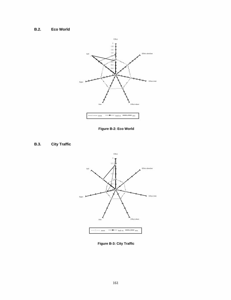
B.2. Eco World
Effect
Effect-absolute
Effect-link
Effect-sheetAim
Super
Self
0
0.2
0.4
0.6
0.8
1
1.2
1.4
1.6
1.8
2
norm built in new
Figure B-2: Eco World
B.3. City Traffic
Effect
Effect-absolute
Effect-link
Effect-sheetAim
Super
Self
0
0.5
1
1.5
2
2.5
3
norm built in new
Figure B-3: City Traffic
161

B.4. Segregation
Effect
Effect-absolute
Effect-link
Effect-sheetAim
Super
Self
0
0.2
0.4
0.6
0.8
1
1.2
1.4
1.6
1.8
2
norm built in new
Figure B-4: Segregation
B.5. Networks
Effect
Effect-absolute
Effect-link
Effect-sheetAim
Super
Self
0
0.2
0.4
0.6
0.8
1
1.2
1.4
1.6
1.8
2
norm built in new
Figure B-5: Networks
162

B.6. Packets
Effect
Effect-absolute
Effect-link
Effect-sheetAim
Super
Self
0
0.2
0.4
0.6
0.8
1
1.2
1.4
1.6
1.8
2
norm built in new
Figure B-6: Packets
B.7. Village of Idiots
Effect
Effect-absolute
Effect-link
Effect-sheetAim
Super
Self
0
0.2
0.4
0.6
0.8
1
1.2
1.4
1.6
norm built in new
Figure B-7: Village of Idiots
163

B.8. Maslow’s Village
Effect
Effect-absolute
Effect-link
Effect-sheetAim
Super
Self
0
0.2
0.4
0.6
0.8
1
1.2
1.4
1.6
1.8
norm built in new
Figure B-8: Maslow’s Village
B.9. Petri Nets
Effect
Effect-absolute
Effect-link
Effect-sheetAim
Super
Self
0
1
2
3
4
5
6
7
norm built in new
Figure B-9: Petri Nets
164

B.10. Voice Dialog Design Environment
The following charts show how the Voice Dialog Design Environment changed over time.
B.10.1. November 1993 (total)
Effect
Effect-absolute
Effect-link
Effect-sheetAim
Super
Self
1
10
100
built in new
Figure B-10: VDDE Total
The usage profiles following are normalized with respect to this usage profile. That is, a voice dialog
design environment usage profile that is proportional to the November 1993 profile would appear as a
circular figure.
165

B.10.2. January 1993 (normalized)
Effect
Effect-absolute
Effect-link
Effect-sheetAim
Super
Self
00.20.4
0.60.8
11.2
1.41.61.8
22.22.42.6
norm built in new
Figure B-11: VDDE Old (before AS/Color)
B.10.3. August 1992 (normalized)
Effect
Effect-absolute
Effect-link
Effect-sheetAim
Super
Self
0
0.5
1
1.5
2
2.5
3
norm built in new
Figure B-12: VDDE 1.3
166

B.10.4. December 1991 (normalized)
Effect
Effect-absolute
Effect-link
Effect-sheetAim
Super
Self
00.20.40.60.8
11.21.41.61.8
22.22.42.62.8
33.2
norm built in new
Figure B-13: VDDE 1.0
167

APPENDIX CHISTORY: THE ROOTS OF AGENTSHEETS
Overview
This is a very brief history of the development of Agentsheets starting in 1985 when I was working at
the Asea Brown Boveri Research Center in the Artificial Intelligence group.
168

The Roots of Agentsheets
At the Asea Brown Boveri Research Center in the Artificial Intelligence group we analyzed the paper
and pencil type of representations naturally occurring (i.e., without the presence of knowledge-based
technology) in the practice of design. The designs analyzed ranged in complexity from small power
distributor stations to full-size nuclear power plants. To our surprise we discovered that the main vehicle of
knowledge representation used was not any sort of ad-hoc rule-like language of design but instead the
reoccurring theme of strong visual formalisms. Tables, being the predominant type of visual formalism,
were used to describe the relationships among some number of system parameters (Figure C-1).
Figure C-1: Paper and Pencil Representation of Configuration
Very quickly, tables became the core visual formalisms used in the system that we worked on at the
time, that later would become a commercial expert system. Not unlike in many other expert system
projects, it became apparent that the enterprise of creating a useful knowledge-based system hinges of the
user interface. Even the best conceptual knowledge representation is of very limited use if it is not
packaged into a good user interface. However, rather than packaging many different individual fragments
169

of functionality into separate user-interface dialog components, we used a generic spreadsheet object class
as the user-interface substrate.
The spreadsheet substrate started with a generic functionality similar to that of ordinary spreadsheets but
over time very specific spreadsheet subclasses got added. Spreadsheets were used to visually represent
basic structures such as:
• lists: list of values (e.g., menus)
• matrices: two-dimensional array of values (e.g., choice tables)
• hierarchical outlines: a list of indented objects representing a hierarchical structure (e.g., frame
representation [10, 25, 52, 76]: hierarchy of frames, slots, facets, and values)
All these examples can be viewed as special interpretations of different spatial topologies. For instance a
list is a horizontally or vertically adjacent set of cells.
In a next step we wanted to give spreadsheet users more explicit control over the invocation of functions
or procedures. In the traditional spreadsheet approach, functions get invoked implicitly through
recalculation triggered by changing the value of a cell. We introduced the notion of buttons to spreadsheets.
A cell could look like a button and clicking the button would invoke a user-defined fragment of code.
Starting in 1990 at the University of Colorado, I looked for further extensions to the spreadsheet
paradigm that addressed problems such as:
• Spreadsheet Data Types Are Very Limited (strings, numbers or formulas). It is impossible to have more
complex data structures with multiple slots.
• Spreadsheets Lack Of Explicit Invocation Paradigm: unlike our button cell, conventional spreadsheet
cells do not support an explicit interaction and invocation model. The button model extension mentioned
earlier does go beyond conventional spreadsheets but not far enough. This leads to the idea that each cell
should become a full-fledged object in the object-oriented sense. This object would have methods to
define its behavior and slots to capture the state of the object. A set of predefined methods would deal
with the human-computer interaction: a set of methods to deal with input (keyboard and mouse) and a
set of methods to deal with output (how to display the state of the object).
Similar to Piersol [90] I began to realize that the representation of the object state was not limited to
strings of characters but instead could include pictures. Unlike Piersol, however, I was not interested just in
individual cells having pictures. Instead, I wanted each individual picture to be part of a whole.
The increase of input/output bandwidth led to adding the notions of sensors and effectors to cell objects.
This new model was finally called an agent and it was oriented toward a simplistic cognitive model in
170

which an external world was perceived through sensors such as eyes, the perception was interpreted, and a
reaction was formulated and executed. The reaction was simply either mental or physical, in which case the
external world was modified through the use of effectors. Later, the set of sensors and effector got extended
with the ability to play sound, speak, or play a movie.
In many applications using the early versions of Agentsheets it became apparent that the reactive nature
of agents was insufficient. Applications involving the simulation of creatures or human-like entities
required a more autonomous mechanism. Agents could be controlled by a user (direct manipulation) or they
could autonomously take the initiative without having to react to a user stimuli first and initiate actions.
With the introduction of the ability for agents to move, the one-cell one-agent mapping became
obsolete. What should happen if an agent moves to a location that is already occupied by another agent?
The notion of agents as cells got replaced with the notion of cells just being locations where an arbitrary
deep stack of agents could reside.
All these extensions to spreadsheet can be viewed as generalizations. Despite the strong tendency of
Agentsheets for diagrammatic representations, there are special agent classes provided including simple
formula evaluation to create “ordinary” spreadsheets.
171