Agenda for last meeting during April, 2007 Visit - EWB … · 6 pedazos de varilla de 10 mm, cada...
13
APPENDIX H H.1 Summary of Plumbing Rules and Regulations, April 2007 H.2 Instructions for Building Concrete Pressure-Break Tanks with the Gates Form, April, 2008 H.3 Fencing for Source Area Protection, October 2008 H.4 Tank Lids Fabricated for Concrete Tanks, 2008
Transcript of Agenda for last meeting during April, 2007 Visit - EWB … · 6 pedazos de varilla de 10 mm, cada...

APPENDIX H
H.1 Summary of Plumbing Rules and Regulations, April 2007 H.2 Instructions for Building Concrete Pressure-Break Tanks with the Gates Form, April, 2008 H.3 Fencing for Source Area Protection, October 2008 H.4 Tank Lids Fabricated for Concrete Tanks, 2008

H.1 SUMMARY OF PLUMBING RULES AND REGULATIONS
The guidelines presented below were developed for repairs and upgrades to the drinking water system (sistema consumo humano) during the EWB April 2007 visit, as a cooperative effort between EWB*, Pam Gilbert, and Jill Sare, Paulino Sacatoro and the 6 master plumbers. The guidelines were prepared to benefit the communities of Malingua Pamba, Tunguiche, Pucara and other areas receiving water from the drinking water distribution systems. EWB suggested line sizing: Use of Valves
• ½” line for 1 – 2 houses • ¾” line for 3 - 5 houses • 1 – 1½ “ for 6 or more
• Valves are for the tanks • Purpose is for draining and cleaning of the
tanks Plumbing Installation Guidelines Tanks
• Do not use glue with barbed couplings • Put hose end in boiling water prior to inserting coupling • Use hose clamps with barbed couplings • Do not cover repair for one day to check for leaks.
• Clean regularly • Drain to remove sand and gravel
When installing new lines:
• Install a wye “y” when connecting to a principal line so that only part of a system needs to be shut down for repairs.
• Do not install lines in cultivated fields o IF absolutely necessary, plant shallow rooted crops above, i.e. pasto melin
• Bury pipes at least 0.75 meter deep • Make a sketch of the location of the line including
o new or old pipe plus what kind o size of pipe o length of the line o type of couplings o name of maestro plumber doing installation
Plumbing Tools left for exclusive use of the Maestros in exchange for their Name Badge.
Maestros de Plomería de Malingua Pamba Maestros de Plomería de Tunguiche & Chimbusi in order (after Brad and Pam): Aurelio Otto Carlos Otto Segundo Otto
Enrique Huishca (not pictured) Euclides Cuchipe Abelino Huishca

H.2 Instructions for Using Gates’ Reusable Tank Form, Spanish/English

Instrucciones para construir un tanque de cimento Introducción Estas instrucciones servirán de guía para la construcción de un tanque completo. Los maestros y muchos miembros de la comunidad ahora tienen experiencia con la construcción de tanques con estos materiales y estas herramientas. Si hay que tomar decisiones sobre la sustitución de materiales, u otras situaciones inesperadas, será esencial acudir al juicio de estas personas ya experimentadas. Los moldes están diseñados para ser utilizados muchas veces, así que es muy importante cuidarlos bien. Materiales 24 paneles del molde (incluyendo las tablas usadas por dentro y por fuera) 4 barras cortas de hierro para las esquinas del base 50 barras medianas de hierro para los rincones interiores y para las soportes 4 barras largas de hierro para el exterior del molde (tienen pintura roja) 4 tablas estrechas para el base 48 abrazaderas en forma de U 4 cintas de nailo para levantar la forma interior y ponerla sobre el base 8 tablas de madera, cada una de 30.48 cm x 122 cm (12 pulgadas x 48 pulgadas) para poner debajo mientras arman el molde, y luego para pisar, para que no asiente molde en el concreto, y finalmente para poner encima del tanque fundido antes de poner el plástico con saquillas de arena 24 pedazos de varilla de 8 mm, cada uno 1 metro de largo doblado en ángulo de 90 grados a 7.6 cm (3 pulgadas) del final (en el metro incluye el doblado) 4 pedazos de varilla de 8mm, cada uno 274 cm (9 pies) de largo, doblado a un ángulo de 90 grados a 81 cm (32 pulgadas) del final 4 pedazos de varilla de 8 mm, cada uno 117 cm (46 pulgadas) de largo, doblado a un ángulo de 90 grados a 56 cm (22 pulgadas) del final 6 pedazos de varilla de 10 mm, cada uno 142 cm (56 pulgadas) de largo ½ litro – 1 litro de aceite vegetal (de cocina) 2 a 5 trapos o brochas para aplicar el aceite 12-14 quintales de cimento 36 saquillas de arena (no muy fina, limpia de plantas, raíces y piedras) 89 saquillas de ripio (lo ideal es que cada piedrita sea entre 2 y 5 cm) 1 malla de varilla para contrapiso de 122 cm x 244 cm (48 x 96 pulgadas),
los bordes doblados hacia abajo para que se quede 3-6 cm sobre la tierra 48 soportes del alambre reforzado 4 tubos galvanizados armados con neplos para conexión de tubería.
(neplos de 40 mm x 1 ¼ pulgadas con 2 adaptadores hembra en medida total de 15.2 cm (6 pulgadas) – cubierto con cinta de embalaje en las de hilo de adaptador rellenar con esperma y por dentro protegido con cartón.
100 pedazos de alambre fino, cada uno 30.5 cm (1 pie) de largo 2 velas para sellar las roscas de los tubos 2 rollos de cinta blanca de teflon para apretar las roscas 1 plástico grande (para cubrir el tanque) 2 llave ajustable 3 palas planas 5 martillos 8 pedazos de cinta de embalaje para las puntas 2 palas pequeñas puntunas 2 bailejos de acero 2 lianas de metal 5 baldes de plástico del mismo tamaño para medir materiales 5 baldes de metal para cargar cimento mezclado 1 nivel 1 codal para anivelar el cimento del base (274 cm de largo) 2 tablas grandes de madera (pleeybo triple) para mezclar el cimento (aproximadamente 180 cm x 240 cm) 1 cepillo de acero para limpieza de los pernos 2 metros

2 cortadores de acero, 1 pequeño para alambre, 1 grande para soportes Agua para mezclar y limpiar
Como preparar el sitio Todas las ubicaciones los tanque deben tener la cooperación del propietario y de la comunidad afectados. Ubica un sitio en tierra estable que no ha estado molestado, con buen acceso a un lugar para sobreflujo que no contribuirá a la erosión del suelo. Prepara el sitio, anivelando un espacio lo suficiente amplio para el tanque más un espacio para trabajar alrededor del tanque. Verifica que esté bien plano utilizando un nivel. El sitio debe ser aproximadamente 4 metros por 4 metros (12 pies x 12 pies). Toma en cuenta la ubicación de las líneas de agua (entrada y salida), sobreflujo, descarga, limpieza, etc. La altura del sitio del tanque debe de estar entre 30 y 60 metros (100 y 200 pies) más alto que los grifos que serán el punto de uso. Debe de haber agua disponible cerca del sitio para poder mezclar concreto y limpiar herramientas. Preparación y fundición del base del tanque Pon los paneles del molde en su lugar, tomando en cuenta su ubicación dentro del espacio total de trabajo. Fija en cuáles paneles son para los lados izquierda y derecha del base y que el lado correcto está por arriba. Las esquinas han sido indicadas para asegurar que las esquinas correctas se juntan. Una vez en su lugar, mide las dimensiones diagonales y mueva el base para hacer iguales las dos medidas diagonales. Luego, mete las barras cortas de hierro, y después las barras medianas. Mételas completamente en la tierra. Pon dos saquillas de arena contra la parte exterior para asegurar que los paneles no mueven una vez fundido el concreto. Con un trapo o una brocha, pon aceite en el interior de los moldes, las bisagras, y los bordes encima y de los lados. Usa un cepillo de acero para limpiar las aperturas roscadas del panel delantero y pon aceite sobre estas también. Pon la malla de varilla dentro del molde del base y mete algunas piedras debajo de la malla para apoyarla 3 a 6 cm (2 a 3 pulgadas) encima del suelo para que no se caiga con el peso del concreto. Fija bien en donde estará el drenaje para asegurar que la malla no bloquea el drenaje. Va a drenar donde el base tiene forma de V. Cerca de la base, prepara una plataforma de madera para mezclar el concreto. Mezcla con estas proporciones (todos los baldes deben ser del mismo tamaño) 1 balde muy lleno de cimento 2 baldes justo llenos de arena 3 baldes de ripio (cada piedrita entre 1-2 pulgadas / 2-3 cm es ideal) ½ - 1 balde de agua (agrega agua lentamente y con cuidado – el concreto debe ser bastante seco) Nota: 1 saquilla de arena = 2 baldes de arena

1 saquilla de ripio = 1 ¼ baldes Total de materiales para un tanque: 12-14 quintales de cimento 36 saquillas de arena 89 saquillas de ripio Introduzca el concreto (no muy mojado!) en la forma del base y aplástalo para sacar el aire. (Usa varilla, cabo de azadón, o los pies). Nivelar las superficies. Si la tierra alrededor de la base está muy seca, salpica agua para que el suelo no chupe el agua del concreto. Empieza la fundición de las paredes mientras la base está todavía mojada para asegurar una unión fuerte. Creación de las paredes interiores del tanque Arma las formas de las paredes interiores del tanque cerca de la base, utilizando las abrazaderas U para juntar los paneles. Las formas interiores se identifican por los soportes de aluminio. Usa las cintas de nailo, una en los huecos de cada esquina, para levantar las paredes armadas y colocarlas sobre la base. Mide bien para asegurar que está bien centrada sobre el base, y que no esté chueca. Es importante que el borde de abajo del molde no caiga dentro del concreto porque será difícil sacarlo después. Mete un soporte de alambre en cada hueco de los paneles interiores, luego fijarlos con barras medianas en las aperturas de los soportes. Ten cuidado de no dejar caer las barras en el concreto. Puedes amarrarlos si sea necesario. Toma los 24 pedazos de varilla de un metro y pon una verticalmente 2 a 3 cm a la derecha de cada soporte al exterior del molde interior. Hunde la parte doblada de cada varilla profundamente en el concreto mojado de la base. Usa pedazos cortos de alambre para amarrar cada pedazo de varilla a cada soporte, manteniendo un espacio de 2-3 cm entre los dos pedazos para que el alambre pueda mover. Amarra las barras largas de varilla a las barras verticales y no a los soportes. Así los soportes podrán mover. La varilla larga debe permanecer 8 cm de las paredes interiores, y 10 cm del rincón interior. No deben estar demasiado cerca de ni el molde interior ni el molde exterior. Creación de las paredes exteriores del tanque Arma los paneles delanteros, juntándolos con abrazaderas U. Pon aceite donde tendrán contacto con el concreto y en las uniones. Coloca un tubo para servir del drenaje, con un extremo del tubo contra la pared interior y el otro extremo colocado donde hay la V en la parte delantera de la base. Coloca la pared delantera, metiendo los soportes en los huecos de las paredes exteriores, asegurando que los pernos de la base entran en los huecos de los paneles exteriores. Mete las barras más largas a través de las aperturas de los soportes, como antes. Cerca del tanque, arma cada grupo de paneles, juntándolos a las paredes a la izquierda, derecha y la pared atrás con las abrazaderas U. Pon aceite en las paredes donde tendrán contacto con el concreto y en las uniones. Pon las paredes en su lugar en la orden correcta, una a una, metiendo las barras medianas por las aperturas y amarrándolas con los alambres cortos. Mete las barras por las aperturas en los rincones también. Pon la madera que sobra en el base, dentro del tanque para poder pararse. Entre el tanque y use los bailejos y lianas para formar el piso de manera que baje levemente hacia la apertura de drenaje. Pon los tubos galvanizados (armados con los neplos) en el espacio de la pared – uno para la entrada, uno para el sobreflujo, y uno para la salida. El tubo de sobreflujo debe estar colocado para que el tope del tubo quede a 7 a 8 (3

pulgadas) cm del borde encima del tanque. El tubo de salida debe estar ubicado para que el tope del tubo esté a 30 cm (12 pulgadas) del fondo de la pared. (Verifica estás ubicaciones con el tanque Brad). El tubo de entrada debe estar a 15 cm (6 pulgadas) del borde encima de la pared. En la misma plataforma, mezcla el concreto en las mismas proporciones como antes. Introduzca el concreto en el espacio entre las paredes, constantemente sacando el aire. Evita pegar la varilla y los alambres porque esto hará que los moldes hundan en el base y serán difíciles de sacar después. Evita derramar concreto dentro del tanque….si ocurre, utiliza un bailejo para sacarlo manteniendo el base liso. Verifica que los moldes de las paredes no se hayan hundido en el base. Si sea necesario, utiliza un bailejo para sacar el concreto contra las paredes para poder sacar los paneles después. Cuando las paredes están llenas de concreto, alisa la cima con un bailejo, poniendo pedazos de madera a lo largo de las cimas de las paredes y cubre el tanque entero con un plástico encima de la madera. Pon saquillas de arena encima de la madera para sujetar el plástico. Deja secar suficiente tiempo (mínimo 3 días) para que seque lentamente el concreto. Como sacar los moldes Después de tres días, destapa el tanque. Utiliza el cortador de acero para cortar las aperturas de los soportes y saca las barras. Utiliza un martillo para sacar las abrazaderas U. Saca los moldes del concreto con mucho cuidado para no dañarlos. Fíjate en las uniones con ángulos porque estos determinan la orden en que se puede sacar los paneles. Cuando se han quitado todas las partes del molde y el tanque está completo, limpia bien todos los paneles del molde y todas las herramientas. OJO – el concreto secará en las aperturas. Utiliza un soporte para limpiarlas antes de que seque. Usa el cepillo de acero para sacar el concreto de los tornillos en el panel delantero. Guarda todo con cuidado en la bodega. Cubrir el tanque Para prevenir la contaminación del agua y que se bloquea el sistema, hay que cubrir el tanque. La tapa debe impedir que entre la luz del sol (para que no crezcan las algas). Asegura que la tapa no vuele en el viento y que se la puede sacar para poder limpiar el tanque periódicamente.

CONSTRUCTION OF PRESSURE BREAK TANKS WITH GATES FORMS
Introduction These instructions are to be used as a guideline for the construction of a complete tank. The maestros and many members of the community now have experience with building tanks with this equipment, and their judgment is critical for making decisions about substitution of materials and other situations that may occur. The concrete forms are designed for repeated use with proper care, so it is important to take care of them. Materials 24 inside and outside panels 4 short iron bars for forms 50 medium iron bars for forms 4 long iron bars for forms 4 narrow base form strips 48 U-clamps 4 nylon straps 8 plywood strips, 1 foot by 4 foot 24 pieces of 8 mm rebar, each 39 inches long, with 90-degree bend at 3 inches from end 4 pieces of 8 mm rebar, each 9 feet long, 90-degree bend at 32 inches from end 4 pieces of 8 mm rebar, each 46 inches long, 90-degree bend at 22 inches 6 pieces of 10 mm rebar, each 56 inches long Cooking oil, ½ liter at least 2 or more brushes or rags for applying oil 12 bags of cement (50 kg) each 36 sandbags of sand (free of roots, plants, stones and debris, and should not contain very fine material) 89 sandbags of gravel (gravel should be no larger than 2 inches, with 1 inch being ideal) Wire grid, measuring 48 in. by 96 in. Bend the outside edges of the grid so that when on the ground, the grid will rest 2-3 inches off the ground. 48 wire form double-loop ties 4 galvanized steel 1.25 in. by 6 inch lengths of pipe, threaded at each end, for wall penetrations 100 lengths of small wire, 1 foot long Candle wax for sealing pipe threads Teflon tape Tarp to cover tank Adjustable wrench 3 flat-edge shovels 5 hammers Duct tape 2 pointed trowels 2 flat trowels 5 equal sized buckets(volume?) for measuring 5 metal buckets for hauling concrete level screed board, approx. 9 feet long Plywood for concrete mixing platform, approx. 6 feet by 8 feet Available water for mixing and cleaning Wire brush 2 tape measures -----------------wire cutters Site Preparation All locations should have the cooperation of the landowner and affected community. Locate a site on stable, virgin soil that has been undisturbed, with good access to a place for overflow runoff that will not contribute to soil erosion. Prepare the site by grading it level and smooth, covering an area large enough for the tank, plus working area around the tank. Check the site using a level. Approximately 12 feet long and 12 feet wide (4 m by 4 m). Consider the location of the feed water line, exit water line, overflow, and cleaning discharge. As a guideline, the elevation of the tank should be no less than 100 feet above, and no more than 200 feet above the point of use. Available water should be nearby for mixing concrete and cleaning tools.
Creation of the tank base Place the concrete forms in place, paying careful attention to their placement within the work area. Note which form panels are for the left and right side of the base and that the correct side is up. The corners have been marked to be sure that the correct corners are matched. Once in place, measure the diagonal dimensions and move the form to make each diagonal equal. Then, drive the corner stakes (these are the smallest of the stakes) and side panel stakes at the hinge (these are the middle size stakes) fully into the ground. Place two sandbags against the outside of each form panel to keep the panels from moving once the concrete is poured. Oil the inside of the forms, the hinges, and the top and side edges. Use a wire brush to clean the threaded openings in the front panel, and oil those as well. Place the wire grid inside the base forms, and place a few rocks under the grid to keep it supported about 2-3 inches off the ground, so it does not collapse once the concrete is poured. Pay attention to the area where the tank drain will be, to be sure that the wire mesh will not block the drain. This is located where the base form is V-shaped. Prepare a wood platform nearby for mixing concrete. Mix concrete using the following proportion: 1 bucket of cement, piled high 2 buckets sand, level with the top of the bucket 3 buckets gravel, gravel should be no larger than 2 inches, with 1 inch being ideal Note: 1 sandbag of sand = 2 buckets of sand 1 sandbag of gravel = 1.25 buckets Total on site = 12 bags of cement (50 kg each), 36 sandbags of sand, 89 sandbags of gravel Pour concrete into base form, and tamp it into place, removing air pockets. Grade the base smooth with the long boards. If the ground around the base is dry, sprinkle some water around the base, so the ground does not absorb the water from the concrete. Begin the next step while the base is still wet, so the base makes a strong connection with the walls. Creation of the tank interior walls Assemble the interior tank forms together near the tank base, using the U-clamps to join the panels. The interior forms are identified by the aluminum metal brackets. Use the 4 nylon straps, 1 at each corner, passed through the holes in the panels, to lift the assembly onto the base. Measure its placement to be sure it’s centered and square with the base. It is important that the bottom edge of the interior form not settle into the concrete, because it will be difficult to remove them later. Slide a wire double-loop tie through each slot on the interior panels, then hold each in place by sliding the medium length iron bar through the loops. Be careful to not let the iron bars fall into the concrete base, by tying them in place if needed. Take the 24 pieces of 39 inch rebar, and place each one vertically about 1 inch to the right of the wire tie, on the outside of the interior form. Press the bent end of the rebar deep into the wet concrete base. Using the short lengths of small wire, tie each piece of rebar to both double-loop wire ties, maintaining a 1 inch space between the two pieces so the looped tie is allowed to move freely. The nine-foot lengths of rebar are to be loosely tied to the vertical rebar, not to the butterfly. This will allow the butterflies to continue to move freely. The rebar should be kept 3 inches from the interior walls, and 4 inches from the interior corner. They should not be closely against either the inside or outside form panel. Creation of the tank exterior walls Assemble the front panel walls together using the U-clamps. Oil the panels where they will contact concrete and at the joints. Place one length of pipe to serve as the drain, with one end of the pipe against the internal wall and the other end resting where the base forms a “V” at the front of the base. Move the front wall into place, sliding each loop through the panel slot, and being sure that the bolts on the base go through the hole on the external panel. Slide the longest iron bars through the outside loops as before.

Near the tank, assemble each set of panels into the left, right, and rear wall using the U-clamps. Oil the walls where they will contact concrete and at the joints. Put each wall into place in the correct order, one at a time, sliding the medium-length iron bars through the loops and securing into place with the short lengths of wire. Put the iron bars through the corner loops as well. Place extra plywood on the base inside the tank to stand on, then climb in and use a trowel to shape the floor of the tank to have a smooth slope toward the drain opening. Place the lengths of galvanized pipe in the wall space. One for the entry, one for overflow, and one for the water exit. One pipe, used for the overflow, should be placed so that the top of the pipe is 3 inches from the top of the form. The outlet pipe should be placed so that the top of the pipe is 12 inches from the bottom of the wall. (to be verified against tanque Brad) The inlet should be 6 inches from the top of the wall. On the same concrete mixing platform, mix concrete in the same proportions as before. Pour concrete into the wall space, continuously tamping to remove air pockets. Try to avoid hitting the rebar and wire ties when tamping, because this will make the forms sink into the concrete base, making them difficult to remove later. Avoid spilling the concrete inside the tank – if it happens, use a trowel to remove the debris to keep the bottom smooth. Also check that the tank wall forms have not sunk into the base. If they have, use a trowel to take away the concrete against the walls so the panels can be easily removed later. When the walls are filled with concrete, smooth the top with a trowel, place the plywood pieces along the tops of the walls, and cover the entire tank with a tarp. Place sandbags on top of the tarp on top of the plywood panels to keep the tarp from blowing away. Allow sufficient time to dry. Removal of forms Three days later, uncover the tank. Use the wire cutters to cut the loops of the wire ties, and remove the iron bars. Use a hammer to remove the U-clamps. Remove the forms from the concrete, being careful not to damage them. Pay attention to the angled joints, because they determine the order in which the panels can be removed. When the forms are removed and the tank is complete, clean all forms and tools. Concrete will dry in the slots in the panels, so another butterfly should be used to clean the slots before it dries. Use a wire brush to scrape away concrete from the screws on the front panel. Everything should be stored in the bodega. Cover the tank In order to prevent contamination of the water and the introduction of clogs in the system, the tank must be covered. Cover it enough so that debris cannot enter, and that sunlight cannot reach the water to prevent algae growth. Be sure the cover is secure in wind, and that enough of it can be removed to allow for complete cleaning periodically.

H.3 Fencing for Source Area Protection, October 2008
Post Forms • Designed by Paulino Sacatoro • 10 forms were used to pour 280 posts.
Posts
• Height: 220 cm • Cross-section: ~ 10 x 10 cm • Weight: 46 kg = 100 lb
Construction of posts:
• 2 sm & 1 lg rebar • 6 figure-8 wire/hooks around rebar • The wire/hooks spaced 13 cm apart
Fencing
• Posts set 50 cm in ground • Posts set 8-10’ apart • At least 4 strands of wire
Fencing around Tanque Pinball, Protective tank for D-2 source spring, photos below • ~40 posts used • One opening • Gate design pending
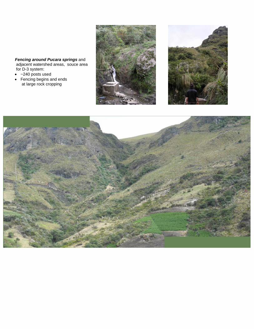
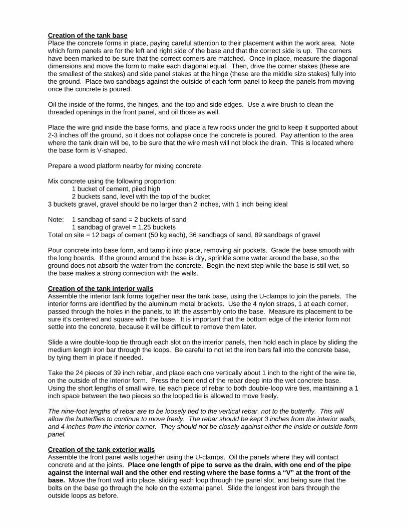
Fencing around Pucara springs and adjacent watershed areas, souce area for D-3 system: • ~240 posts used • Fencing begins and ends
at large rock cropping

H.4 Tank Lids Fabricated for Concrete Tanks, 2008
Tanque Pinball, upper photos; Tanque Brad, lower photos
• Designed by Paulino Sacatoro, fabricated in Latacunga • Cost of lids for Tanque Pinball, Brad, Esteban & Cristobal, $265, each, 2008. • Bolted into place on tank • Hinged opening so that lid can lay flat • Two hooks so that a padlock could be used to secure the lid.