After 40 Years Why Hasn’t the Computer Replaced the Wind ... · After 40 Years Why Hasn’t the...
19
After 40 Years Why Hasn’t the Computer Replaced the Wind Tunnel? Edward M. Kraft, Ph.D. USAF Arnold Engineering Development Center, Arnold Air Force Base, Tennessee The debate between wind tunnels and computers to develop aeronautical systems has persisted for over 40 years. On the one hand, the majority of wind tunnels used today in aeronautical research, development, test, and evaluation were designed and commissioned in the 1950s and ’60s. These facilities remain the backbone of the aeronautical development process, although they are becoming more challenging to maintain. On the other hand, rapid advances in computer hardware and software offer the potential to dramatically alter the design and development process for flight systems through the application of computational science and engineering. However, after 40 years of promises to eliminate the need for test facilities, advanced computational science and engineering have still not diminished significantly the need for test facilities or reduced the overall cycle time for development of flight systems. As many wind tunnel test hours are used today to develop a flight system as were used 20 years ago. Key words: Aeronautical development; computational science and engineering; experience; high-fidelity modeling and simulation; performance prediction; physics modeling reliability; test facilities; validation & verification. N ow that I have your attention, the title of this article is actually the wrong question! The proper debate needs to be centered on how Com- putational Science and Engineering (CSE) and wind tunnel testing can be integrated to reduce the overall cycle time for development of an aeronautical system. If CSE could actually eliminate the use of wind tunnels in system development, the net gain to the acquisition program would be fractions of a percentage in cost savings. On the other hand reducing the overall cycle time by merging CSE and wind tunnel testing could reduce total development cycle time by months to years, resulting in billions of dollars of savings. This article is focused on understanding the challenges to using computational methods; delineat- ing changes required in people, processes, and tools to make CSE more effective; and creating a vision for an integrated CSE/testing approach to reduce develop- ment cycle time. First, for clarity, we need to define what we mean by CSE relative to the ubiquitous phrase ‘‘Modeling and Simulation (M&S).’’ For this article, we will focus our attention on high-fidelity, physics-based modeling and simulation as opposed to engagement or theater wargaming models. The former, which we will refer to as CSE, is more directly reflective of the aeronautical design process and the way test facilities are used to develop systems. The latter, which we will refer to as M&S, is more associated with doctrine, tactics and techniques, and training for the Depart- ment of Defense (DoD). Also, we will use the terminology CSE to connote that we are talking about the entire spectrum of physics-based modeling such as Computational Fluid Dynamics (CFD), Computa- tional Structural Mechanics/Computational Structural Dynamics (CSM/CSD), computational electromag- netics, or computer-aided engineering. Embodied in these modeling activities are also computational heat transfer and chemical kinetics. It is important for our discussion to maintain the distinction between M&S and CSE. M&S and CSE are both computational simulations, but within the upper levels of the DoD, M&S is ascribed to any and all computational simulations. In reality, the DoD focuses its management structure and funding on wargaming and training M&S. Aside from the activities of the Office of the Secretary of Defense (OSD) High Performance Computing Modernization Office (HPCMO), CSE has largely been left in the hands of Science and Technology (S&T), test and evaluation, and engineering function within the ITEA Journal 2010; 31: 329–346 31(3) N September 2010 329
Transcript of After 40 Years Why Hasn’t the Computer Replaced the Wind ... · After 40 Years Why Hasn’t the...

After 40 Years Why Hasn’t the Computer Replaced theWind Tunnel?
Edward M. Kraft, Ph.D.
USAF Arnold Engineering Development Center, Arnold Air Force Base, Tennessee
The debate between wind tunnels and computers to develop aeronautical systems has persisted
for over 40 years. On the one hand, the majority of wind tunnels used today in aeronautical
research, development, test, and evaluation were designed and commissioned in the 1950s and
’60s. These facilities remain the backbone of the aeronautical development process, although they
are becoming more challenging to maintain. On the other hand, rapid advances in computer
hardware and software offer the potential to dramatically alter the design and development
process for flight systems through the application of computational science and engineering.
However, after 40 years of promises to eliminate the need for test facilities, advanced
computational science and engineering have still not diminished significantly the need for test
facilities or reduced the overall cycle time for development of flight systems. As many wind
tunnel test hours are used today to develop a flight system as were used 20 years ago.
Key words: Aeronautical development; computational science and engineering;
experience; high-fidelity modeling and simulation; performance prediction; physics
modeling reliability; test facilities; validation & verification.
Now that I have your attention, thetitle of this article is actually thewrong question! The proper debateneeds to be centered on how Com-putational Science and Engineering
(CSE) and wind tunnel testing can be integrated toreduce the overall cycle time for development of anaeronautical system. If CSE could actually eliminatethe use of wind tunnels in system development, the netgain to the acquisition program would be fractions of apercentage in cost savings. On the other hand reducingthe overall cycle time by merging CSE and windtunnel testing could reduce total development cycletime by months to years, resulting in billions of dollarsof savings. This article is focused on understanding thechallenges to using computational methods; delineat-ing changes required in people, processes, and tools tomake CSE more effective; and creating a vision for anintegrated CSE/testing approach to reduce develop-ment cycle time.
First, for clarity, we need to define what we mean byCSE relative to the ubiquitous phrase ‘‘Modeling andSimulation (M&S).’’ For this article, we will focus ourattention on high-fidelity, physics-based modeling andsimulation as opposed to engagement or theaterwargaming models. The former, which we will refer
to as CSE, is more directly reflective of theaeronautical design process and the way test facilitiesare used to develop systems. The latter, which we willrefer to as M&S, is more associated with doctrine,tactics and techniques, and training for the Depart-ment of Defense (DoD). Also, we will use theterminology CSE to connote that we are talking aboutthe entire spectrum of physics-based modeling such asComputational Fluid Dynamics (CFD), Computa-tional Structural Mechanics/Computational StructuralDynamics (CSM/CSD), computational electromag-netics, or computer-aided engineering. Embodied inthese modeling activities are also computational heattransfer and chemical kinetics.
It is important for our discussion to maintain thedistinction between M&S and CSE. M&S and CSEare both computational simulations, but within theupper levels of the DoD, M&S is ascribed to any andall computational simulations. In reality, the DoDfocuses its management structure and funding onwargaming and training M&S. Aside from theactivities of the Office of the Secretary of Defense(OSD) High Performance Computing ModernizationOffice (HPCMO), CSE has largely been left in thehands of Science and Technology (S&T), test andevaluation, and engineering function within the
ITEA Journal 2010; 31: 329–346
31(3) N September 2010 329

Report Documentation Page Form ApprovedOMB No. 0704-0188
Public reporting burden for the collection of information is estimated to average 1 hour per response, including the time for reviewing instructions, searching existing data sources, gathering andmaintaining the data needed, and completing and reviewing the collection of information. Send comments regarding this burden estimate or any other aspect of this collection of information,including suggestions for reducing this burden, to Washington Headquarters Services, Directorate for Information Operations and Reports, 1215 Jefferson Davis Highway, Suite 1204, ArlingtonVA 22202-4302. Respondents should be aware that notwithstanding any other provision of law, no person shall be subject to a penalty for failing to comply with a collection of information if itdoes not display a currently valid OMB control number.
1. REPORT DATE SEP 2010 2. REPORT TYPE
3. DATES COVERED 00-00-2010 to 00-00-2010
4. TITLE AND SUBTITLE After 40 Years Why Hasn’t the Computer Replaced the Wind Tunnel?
5a. CONTRACT NUMBER
5b. GRANT NUMBER
5c. PROGRAM ELEMENT NUMBER
6. AUTHOR(S) 5d. PROJECT NUMBER
5e. TASK NUMBER
5f. WORK UNIT NUMBER
7. PERFORMING ORGANIZATION NAME(S) AND ADDRESS(ES) USAF Arnold Engineering Development Center,Arnold AFB,TN,37389
8. PERFORMING ORGANIZATIONREPORT NUMBER
9. SPONSORING/MONITORING AGENCY NAME(S) AND ADDRESS(ES) 10. SPONSOR/MONITOR’S ACRONYM(S)
11. SPONSOR/MONITOR’S REPORT NUMBER(S)
12. DISTRIBUTION/AVAILABILITY STATEMENT Approved for public release; distribution unlimited
13. SUPPLEMENTARY NOTES
14. ABSTRACT
15. SUBJECT TERMS
16. SECURITY CLASSIFICATION OF: 17. LIMITATION OF ABSTRACT Same as
Report (SAR)
18. NUMBEROF PAGES
18
19a. NAME OFRESPONSIBLE PERSON
a. REPORT unclassified
b. ABSTRACT unclassified
c. THIS PAGE unclassified
Standard Form 298 (Rev. 8-98) Prescribed by ANSI Std Z39-18

government as well as academia and industry. Conse-quently it has evolved in an ad hoc fashion, albeit withgreat success in select areas.
It is also important to understand the difference inthe use of CSE in support of S&T and engineering. Inthe former, great strides are being made in the use ofpeta-flop (1015 floating point operations per second)computing in research approaching the molecular level.‘‘Designer’’ materials are being developed by usingcomputer simulations to manipulate molecules toachieve desired properties. While the S&T communityhas been the principal driver for advances in CSE, ithas only been recently that the engineering communityhas become a key component of the CSE cognoscenti.In the past, the engineering design function has reliedon legacy capabilities and relatively small computersystems. What has become clear in recent years is that amajor justification for developing even larger scalecomputer systems is tied more to the engineeringprocess than to the S&T community (i.e., theeconomic justification is based on the output of theproduct development process for commercial andmilitary systems). The integration of multidisciplinarysimulations and design optimization of aerospacevehicles throughout their mission profile is primarilyan engineering function that can be enhanced by nextgeneration CSE capabilities. It is also the engineeringapplication of CSE that directly competes withengineering use of wind tunnels in the developmentprocess. In this article we will focus on engineeringapplications of CSE.
A celebration of successBefore we launch into a detailed discussion of why
advanced modeling cannot replace testing in the nearfuture, we need to understand that CSE has indeedhad a profound impact on aeronautical systemdevelopment. CSE is aggressively used by the aero-nautical system design community to apply simplerengineering models to reduce the design space to alimited set of design variables that meet requirements.These select configurations are modeled with muchhigher fidelity physics-based models to developprototype designs. Although these designs are notrobust enough to eliminate the need for wind tunneltesting, they do reduce the need for multipleexperimental configuration studies in the wind tunnel.Ironically, advanced computer-based control systems inmodern military aircraft actually drive a need for evenmore wind tunnel data per configuration to ensureaccurate control variables over the entire flightenvelope. CSE is not currently capable of providingthe control system inputs accurately enough to reducethe overall wind tunnel testing requirements.
Once the development phase starts into the windtunnel phase, CSE is heavily used as a complementarytool with testing. Highlights from the application ofCSE at the U.S. Air Force’s Arnold EngineeringDevelopment Center (AEDC) in support of windtunnel testing are summarized in Kraft and Matty(2005). Typical applications include pretest planning toensure optimization of the test facility and instrumen-tation; support to real-time data analysis and decisionmaking; analysis of potential wind tunnel effects such assupport or wall interference; extrapolation of windtunnel data to flight conditions; support to flight testing,particularly weapon separation; and support to opera-tional flight issues that occur after a system has beendeveloped. Also, CSE is an excellent tool late in thedevelopment cycle for evaluating incremental effects aswell as anomalies that show up during flight testing.
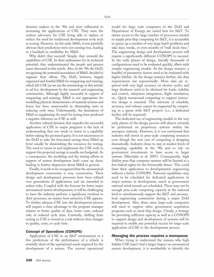
To appreciate the impact of CSE on the aeronauticaldevelopment process, a history of applications of CSEin support of wind tunnel testing at AEDC isillustrated in Figure 1. In the late ’80s and early ’90sserious engineering calculations were being performedeven though the state of the art in computer capabilitywas barely at the giga-flop (109 floating pointoperations per second) level. An inviscid, Eulersolution for an F-15E aircraft complete with stores,pylons, pods, etc., using about 1 million grid pointscould be computed in less than 8 Central ProcessorUnit (CPU) hours, making it a useful engineering tool.The simulation, augmented and validated by windtunnel data, was sufficiently accurate to predict therelease of weapons from the conformal fuel tanks onthe F-1 5E well enough to safely guide flight testing(Kraft 1994).
Using the 1988 calculation of the F-15E as abaseline, subsequent advances in CSE enabled morephysics (unsteadiness and viscous effects) as well asrefined grids to produce more accurate engineeringsolutions in less time. In Figure 1, complexity isdefined as the product of the number of processorsused times the number of grid points times the outputin number of solutions per week. Most of the advancesin capability demonstrated in Figure 1 are attributableto rapid advances in hardware. Today, it is notuncommon to use 30–50 million grid points for atime-accurate, unsteady, viscous simulation of acomplete aircraft and produce a solution in less than8 CPU hours. These advances were made at AEDC,which has aggressively applied CSE to engineeringproblems for over 20 years but has relatively modestcomputing horsepower (Kraft and Matty 2005). Manyof the solutions illustrated in Figure 1 used only 32processors, but today several hundred processors areavailable.
Kraft
330 ITEA Journal

Some of the anecdotal success stories demonstratedwith the CSE applications at AEDC represented inFigure 1 include the following:
N F-15E—first demonstrated use of CFD to modifywind tunnel and flight testing resulting in safecarriage and release as well as improved operationsfor the F-15E. Post-integration of CSE with testingresulted in no flight incidents during certification ofnumerous weapons for carriage and release from theF-15E. The CSE tools developed for the F-15Ehave been persistently updated and applied to everyDoD platform since, with immeasurable reductionsin cost and improvements in safety.
N F-22—an integrated CFD/wind tunnel testingapproach reduced the cost of models by over $8million and provided insight to support anaggressive flight-test program for weapon sepa-ration clearance over the entire flight envelopewith minimum sorties.
N B-1B (not illustrated)—CFD simulations of flareejections eliminated a major part of a flight-testprogram at a cost savings of $500,000 to solve anoperational problem.
N Minature Air-Launched Decoy (MALD)—CFDdesign of fins for use in the wind tunnel enabledhigh-quality data to be obtained in a smaller, morecost-effective wind tunnel.
N Joint Strike Fighter—CFD analyses enabledrefinement of the inlet for the vertical or shorttake off and landing configuration during devel-opment, eliminated a wind tunnel entry for storeseparation simulation resulting in approximately
$1 million savings, and augmented stability andcontrol analyses.
There are numerous additional anecdotal accountsof how CSE has improved wind tunnel testing, but thereal challenge is to develop an improved overallmethodology for the use of CSE with testing todramatically reduce the cycle time for development aswell as improve performance of the systems. Thisarticle formulates the issues keeping CSE from havinga larger impact on development and creates a vision forinnovative ways to integrate CSE and testing.
Why hasn’t CSE already replaced testing?The ‘‘tastes great, less-filling’’ debate between CSE
and wind tunnels has been ongoing for over 30 years).The classic American Institute of Aeronautics andAstronautics (AIAA) Dryden Lecture delivered byDean Chapman in 1979 was the first serious salvo inthe debate (Chapman 1979). Chapman’s visionaryarticle clearly identified the rapid growth in CFDhardware, software, and modeling capabilities thatcould transform the aerodynamic design process. Manyof his CFD projections have been exceeded over thelast 30 years. (He was forecasting breakthroughs onlythrough the ’90s and did not extend his vision to thescale of CSE today.) On the other hand, the averagenumber of wind tunnel hours used in developmentof commercial and military aircraft continued to grow(Melanson 2008) over that same 30-year period despitewind tunnel efficiency increasing by at least a factor offour (Kraft and Huber 2009). At the same time, moreand more DoD programs (and some commercial
Figure 1. Increasingly complex computational fluid dynamics simulations enabled by computer hardware and software advances.
Wind Tunnels & Computers
31(3) N September 2010 331

programs) overrun their original cost and scheduleestimates. So what gives? Obviously CSE has noteffectively changed the aeronautical developmentprocess to the degree envisioned by Chapman.
Very simply, advances in computers even to peta-flop (1015 floating point operations per second)performance and beyond are necessary but not sufficientto transform the aeronautical development process. Ittakes a holistic advance in the integration of people,processes, and tools to enable the kind of revolutionpeople have envisioned for the last 3 decades. Evenmore than the tools, the people and processes need tobe better understood and integrated with the advancedcomputer hardware and software to increase theeffectiveness of CSE in the aeronautical developmentprocess. In the next section, we will explore challengesto the technologies, intellectual capital, and processesthat will have to be overcome to achieve the fullpromise of CSE in the development process.
Technological impedimentsIndeed, large-scale computing power is at our
doorsteps. Although access to peta-flop computers isnecessary for a revolution in applying CSE to aeronau-tical system development, it is definitely not sufficient.Having software that can efficiently and effectively usemassive parallel computing power, having robustalgorithms for complex and multidisciplined applica-tions, improving modeling of essential physical phe-nomena, and systematically verifying and validating thatthe tools will work robustly in the engineeringenvironment are equally important. In this section wewill highlight some of these technical challenges.
Software scalabilityThe trend in high-performance computing archi-
tecture is toward massive parallel processing toupwards of 100,000 CPUs or cores. These trends arebeing driven by the rapidly growing cost of furtherincreases in processor clock speed and the emergence ofpower density and cooling requirements as dominantconsiderations. High-performance computing centersare now requiring megawatts of power for operation.Although peta-flop computers are already available inselect federal computing centers and exa-flop (1018
flops) machines are on the horizon, the legacy CSEsoftware tools routinely applied to design and devel-opment problems have not been scaled to maximize theuse and gain the efficiencies afforded by clusters withtens of thousands of processors. Most codes have beenoptimized to run on fewer than 100 processors. CFDsolution algorithms tend to scale reasonably well, butmany algorithms have topped out around 512 CPUsand only a few have operated with a few thousand
cores. The very best CFD codes scale linearly to 5,000cores, which is three orders of magnitude smaller thanthe potential million-core machines envisioned for thefuture. Even the highest performing CFD algorithmsquickly lose ground when significant Input/Output(I/O) is required to grab and store solutions every fewtime steps for a graphical representation of an unsteadyflow solution. Other CSE algorithms do not scale aswell as CFD codes. Hence, even though peta-flopmachines are becoming available, current softwarescalability limitations do not enable the solvers to useall of the hardware capability. One of the strategies tooffset this near-term lack of scalability is to use a largenumber of available cores to simultaneously solve anumber of parallel cases. This strategy will be useful ineither rapidly reducing the design space in the earlyphases of concept development or in building asignificant CSE data base in later stages of development.
ComplexityAs computer systems have advanced, so has the
complexity of aeronautical systems. Over the last30 years, expanded flight envelopes, super-maneuver-ability, super-cruise, low observables, and advances inmaterials technology have made it more challenging tomodel the physics of military flight systems. Assuggested in Figure 1, all of the advances in computerhardware and software have been absorbed in increas-ing the fidelity of more complex systems.
A significant challenge to developing a full flightsystem is the integration of the major subsystems (i.e.,airframe/propulsion integration, airframe/structure in-tegration, electromagnetic interference, control sys-tems, and airframe/weapon systems). The majordefects frequently found late in the development cyclefor a flight system usually occur at the interface ofmajor subsystems (e.g., aerodynamically induced struc-tural failures). For example, on average for militaryaircraft, 10 structural flaws are found in the flight-testphase even after a comprehensive ground-test cam-paign and massive application of CSE. The fixes forthese structural flaws can range from simple tosignificant, costing as much as $1 billion and delayinga program by a year or more.
Although significant advances in multidisciplinedynamic simulations for maneuvering vehicles havebeen made, the fidelity of current capabilities in termsof grid resolution, model complexity, and interdisci-plinary coupling is still only a fraction of what isneeded in the long run.
Performance predictions versus reliabilityWhat is frequently overlooked by the CSE commu-
nity desiring to replace testing is that test facilities are
Kraft
332 ITEA Journal

used to predict not only the performance, but also theoperability, reliability, and maintainability of anaeronautical system. The majority of the ad hoc successstories in applications of CSE have to do withperformance predictions only. CSE is not capable, forexample, of simulating the aeromechanical perfor-mance of a turbine engine over its mission life toensure that it will be reliable enough to field. It is alsonot capable of simulating the dynamic stressing of itsstructure to assure its reliability to stay ‘‘on wing’’ forhundreds of hours. Similarly, CSE is not robustenough to decide if an engine can be restarted ataltitude or survive a bird strike or debris ingestion.Comparable limitations exist for modeling dynamicfatigue cycles for the aircraft structure. Historical datademonstrate that, on average, ten structural failures arediscovered in flight even after numerous computersimulations have been performed. Consequently, inspite of advances in computer horsepower andapplications of CSE, test facilities will be essential toassure a system is operable, reliable, and maintainable.
Physics modelingThe list of physics modeling challenges that inhibit
the robust application of CSE is legend. The classicalproblems in applying CFD include turbulence model-ing, boundary layer transition, and flow separation. Forrelatively benign attached or mildly separated flow, theuse of Reynolds Averaged Navier Stokes (RANS)codes with the addition of large eddy simulations hasadvanced to a very good engineering capability but stillhas enough inaccuracy to preclude total reliance on thecomputed results. For vortex dominated or massivelyseparated flows typical of advanced tactical aircraft atthe corners of the flight envelope, the CSE tools arenot nearly as capable. The dynamics of separated flowhave a large impact on structural dynamics, stabilityand control, as well as control surface response.
Turbulence modeling may be one of those intrac-table engineering problems that cannot be solved withhigher performance computing. Turbulence modelingin today’s CFD codes is a semi-empirical approxima-tion of the physics of turbulence to support practicalcalculations. To enhance predictions using turbulencemodeling requires decreasing the size of the numericalgrids. To double the resolution of a three-dimensionalflow problem requires a factor of 16 increase incomputer horsepower.
Although the promise of the revolution in computerhardware will enable this, the scalability of the softwarewill make it challenging to fully utilize for realisticgeometries. The step beyond turbulence modelingenabled by high-performance computing is DirectNavier Stokes (DNS) simulations. DNS does not make
approximations to the equations of motion but doesrequire a billion plus mesh point grids. Althoughresearch in this area is progressing for relatively benigngeometries, it will be decades before DNS will beuseful for relevant geometries of flight systems.
High-speed, hypersonic flight bring in anotherrange of physics modeling challenges. At hypersonicconditions, additional physical phenomena such as realgas chemistry, conjugate heat transfer, wall catalicity,shock/shock interactions, etc., create significant prob-lems for CSE. Compounding the physical modelingissue is the dearth of qualified experiments and testfacilities to explore the physics and provide sufficienthigh quality data to validate and verify the models. Forexample, to fully benchmark hypersonic boundary layertransition phenomena would require experiments thatencompass a wide range of Reynolds numbers, Machnumbers, angles of attack, bluntness, favorable andadverse pressure gradients, roughness, waviness, walltemperatures, cross-flow phenomena, surface catalicity,and a range of gas chemistries. Not to be overlooked isthe requirement for advanced flow diagnostic tools thatcan be applied in the high-temperature, high-pressurehypersonic flight regime. A critical review of CSE andtesting for hypersonics, presented in Kraft andChapman (1993), suggests an incremental approachto CSE and testing to overcome the challenges to each.
Validation & Verification (V&V)The aeronautics community has given itself one
huge ‘‘head fake.’’ There are numerous (and growing)conference articles showing ‘‘good’’ comparisons be-tween CSE solutions and select experiments. Thesecomparisons have been the basis for many marketingefforts to try to make the argument that CSE canduplicate test facilities. However, an accumulation ofanecdotal comparisons does not result in a robust tool.Tinoco (2008) probably expressed it best:
‘‘CFD validation cannot consist of the compar-ison of the results of one code to those of oneexperiment. Rather, it is the agglomeration ofcomparisons at multiple conditions, code-to-codecomparisons, an understanding of the windtunnel corrections, etc., that leads to theunderstanding of the CFD uncertainty andvalidation of its use as an engineering tool.Examples include comparisons of predictive CFDto subsequently acquired test data. The question isnot can CFD give a great answer for one or twotest cases, but can the CFD ‘‘processes’’ give goodanswers for a range of cases when run by acompetent engineer? This is what validation foran intended purpose is all about.’’
Wind Tunnels & Computers
31(3) N September 2010 333

The recent AIAA drag prediction workshop com-pared results from a number of state-of-the-art codesapplied by experienced CSE practitioners to theprediction of drag on transonic transport aircraftconfigurations (Vassberg et al. 2008). The workshopprovided a very broad view of the state of the art ofCFD applications within the industry, much more sothan that which can be garnered by an isolated study.In fact, by reviewing in isolation any one of theindividual data blocks, one may arrive at differentconclusions from those determined from the completedata set comparison. For example, a typical publicationmay show how successful a CFD solution matches testdata. By combining a large set of solutions from manysources around the world, this workshop clearlyshowed that there remains much room for improve-ment.
The need for robust V&V also underscores therequirements to put error bars on the computationalresults as well as the experimental results. However,one must exercise caution in doing so. A CSE solution,since it is deterministic for a given computation, willhave zero precision errors but could have excessive biaserrors driven by grid resolution, time steps, numericaldissipation, boundary conditions, and physics model-ing. On the other hand, experimental data can haveboth precision and bias errors. Precision errors at the95% confidence level are usually well documented inthe experiment, but attention needs to be paid to biaserrors driven by geometric modifications of a scaledmodel, Reynolds number scaling, wall interference,support interference, etc. Experimental validation datafor CSE V&V needs to be well documented forprecision and bias errors. Furthermore, comprehensiveV&V of CSE needs clear identification of all boundaryconditions, which will require off-body flow measure-ments for completeness of the experimental data base.
Experience and intellectual capitalIncreasing the use of CSE versus testing is a two-
edged sword relative to the technical talent involved inaeronautical system development. On the one hand,visual output from high-fidelity models providesunprecedented insight into flow features that cannotbe obtained in any other way. Being able to ‘‘see’’streamlines and vortex patterns on flow over a vehiclebrings new understanding in the causative relationsbetween aerodynamic shapes and vehicle performance.The tools also allow relatively rapid evaluation ofchanges to the design, which in its own way introducesmore insight. On the other hand, having a generationof engineers experienced only in the ‘‘zeros and ones’’of advanced modeling has the downside of limiting realunderstanding of the physics of the problem, especiallywhen extending into realms beyond the physicalfidelity of the model. The experiential insight gainedfrom physically measuring phenomena is important intwo ways—it provides more depth in understandingand is absolutely essential to guide development ofmodels to capture the physics. There seems to be acircular argument that we can better model the physicsthan the experiments when the models are only as goodas our physical understanding gained from experi-ments. If we no longer have experimental facilities,how do we advance the physical representation in themodels?
It is painfully apparent in the aerospace industry thatthere has been a significant decline in the experiencebase of aeronautical designers and developers. Asshown in a RAND study, the experience base forpost–World War II engineers was approximately 6–12new design aircraft per career (Drezner 1992). Thenumber of new military aircraft program starts perdecade is shown in Figure 2. In the 1950s there were60 aircraft programs in various stages of development.
Figure 2. Experience trends in aerospace systems development—reduced opportunity for development of intellectual capital.
Kraft
334 ITEA Journal

In contrast, aerospace engineers starting their careerstoday may experience only one, maybe two new systemdesigns during their careers. The decadal decline ofcareer opportunities in other aerospace technical areasis also shown in Figure 2. For most aerospace systemssuch as rocket engines, turbine engines, high-speed X-vehicles, and ground-test facilities, engineers todayhave far fewer opportunities to hone their skills thantheir predecessors. Anecdotal evidence has linked thistrend to problems experienced in many recentaerospace development programs. Counterargumentspoint out that rapid advances in design, manufacturing,and information technologies used in the design anddevelopment process of today’s new design aircrafthave compensated for some or all of the decliningexperience base.
A study was performed at the MassachusettsInstitute of Technology (MIT) to understand whetherthe application of large-scale computer simulation tothe design process would offset the inexperience ofaircraft designers (Andrew 2001). The study exploredresults from multiple aircraft programs covering 4decades from the ’60s through the ’90s. Aircraft weightmanagement through the development cycle is acritical and well-documented parameter that can becompared from program to program and decade todecade. In the study, there was clear evidence thatweight management degraded from decade to decadeand was clearly linked to the level of experience of thedesigners. Key findings from the study included thefollowing:
N Strong linkage exists between experience andperformance.
N Seventies-era design efforts outperformed ’90s erain weight management.
N Test phase is an important downstream indicatorof design performance—test personnel under-stood design flaws through exposure to recurringproblems
N Modern design tools are graphically compelling,but reduced experimental experience led todeficiencies.
While simulation and automation of the designprocess certainly helped, it did not substitute for theintuition and inspiration that contributed to successfulnew and innovative designs. Also, such automation wasonly marginally effective when dealing with new anduntried technologies because the basic informationneeded for the computational algorithms was missingor of low fidelity. Furthermore, it should be clear thatone cannot really assess a design only on the computer.One has to build the prototype and test it, otherwisedesign flaws will flow downstream into manufacturing
and operations. The earlier that design flaws arediscovered through prototype testing the better.
In the MIT study, some negative effect was found tobe associated with today’s computational tools. Not somuch the tools themselves, but with regard to the tacitknowledge derived when interacting with them.Today’s tools are much less effective at developingthe tacit knowledge of the users. Sophisticatedsimulation models of all types, some with realisticgraphic presentations, seem to command a greater levelof creditability than they deserve in many cases. Indigging for a root cause to some design issues, it wasclear that there were significant shortcuts taken withrespect to supporting wind tunnel testing and model-ing efforts needed to develop a model worthy of thelevel of confidence with which it was being applied.
It is hard to envision that the late Richard T.Whitcomb of the National Aeronautics and SpaceAdministration (NASA) Langley Research Centerwould have made his breakthrough contributions toaerodynamics if the only tool he had was a computer.His insights into transonic area ruling, supercriticalairfoil sections, and winglets came about by persistentexperimental research and sound physical understand-ing of the flow phenomena (Hansen 1986). The three-legged stool of theory, experiments, and computationsis necessary to make real advances in the aeronauticalsciences.
ProcessesCSE is just a single tool in the systems engineering
process required to design, develop, and field anaeronautical system. Consequently, if the CSE com-munity and its practitioners are not equally fluent inunderstanding the overall processes, CSE will generallynot have the desired effect on overall development.Ensuring the process environment is conducive tointegration of CSE may be the single most importantconsideration for advancing CSE!
Cultural acceptanceThe application of CFD to aeronautics over the past
40 years has seen some interesting dynamics inacceptance by the community. In the early ’70s whenCFD was just emerging as a viable tool for augmentingaeronautical development, the ‘‘young Turks’’ engagedin its development were enthusiastic about its poten-tial. However, the managers making decisions at thattime had not grown up in an environment of CSE andwere not prone to support a large scale application ofCSE. In reality the tools were not quite mature enoughto have a major effect.
After a generation of CSE fledgling applications,the original ‘‘young Turks’’ became the mid-level
Wind Tunnels & Computers
31(3) N September 2010 335
decision makers in the ’90s and were influential inincreasing the applications of CSE. They were thezealous advocates for CSE being able to replace orreduce the need for traditional development tools suchas testing. However, by the early 2000s, it was painfullyobvious their predictions were not coming true, leadingto a backlash in credibility for M&S.
Why didn’t they succeed? Simply, they oversold thecapabilities of CSE. In their enthusiasm for its technicalpotential, they underestimated the people and processissues discussed in this article. Also, in the ’90s the DoD,recognizing the potential ascendance of M&S, decided toorganize their efforts. The DoD, however, largelyorganized and funded M&S for wargaming and training,which left CSE (as we use the terminology in this article)to ad hoc development by the research and engineeringcommunities. Although highly successful in support ofwargaming and training, M&S is not appropriate formodelling physical characteristics of material systems andhence has been unsuccessful in eliminating tests orreducing cycle time. Unfortunately, the limitations ofM&S in supplanting the need for testing have produceda negative inference on CSE as well.
Another cultural dynamic that impedes the successfulapplication of CSE to major programs is the lack ofunderstanding that one needs to invest in a capabilitybefore taking the promised gains. It is not uncommon inthe DoD to take the forecasted savings from M&S upfront usually by diminishing the resources for testing.The need to invest in and implement the CSE tools tosupport the projected savings is usually not budgeted. Asa consequence, the modeling and the testing efforts insupport of system development both come up short,leading to further skepticism about M&S in general.
Finally, it needs to be recognized that the aeronauticaldevelopment community is very conservative. Theirdesign and development processes have been refinedover generations of applications and are intended toreduce risks. Coupled with the forecast for fewer majoraeronautical system developments, it will be challengingto have the industry perform a significant overhaul totheir processes, no matter how attractive CSE appears.To further advance CSE into the development processwill require a clear advantage to the program managerrelative to better quality of data, lower costs, reducedrisk, or reduced cycle time. Currently, shifting fromtesting to CSE is viewed as a risk without clear changesin quality, costs, or cycle time.
Concept of Operations (CONOPS)Application of CSE in an S&T environment to a
few predictions of the performance of a vehicle iswoefully short of the operational needs required for thedevelopment of a system. The current operational
model for large scale computers in the DoD andDepartment of Energy are suited best for S&T. Toobtain access to the large number of processors neededto supply peta-flop computing for S&T, it is acceptableto queue up a number of very large batch problems andtake days, weeks, or even months of ‘‘wall clock time.’’The engineering design and development process willrequire a significantly different CONOPS to succeed.In the early phases of design, literally thousands ofconfigurations need to be evaluated quickly, albeit withsimpler engineering models. As the design matures, ahandful of parametric factors need to be evaluated withhigher fidelity. As the design matures further, the datarequirements rise exponentially. More data are re-quired with very high accuracy on shorter cycles, andlarge databases need to be obtained for loads, stabilityand control, subsystem integration, flight simulation,etc. Quick turnaround computing to support interac-tive design is essential. This intensity of schedule,accuracy, and volume cannot be supported by compet-ing in a queue with S&T projects (i.e., a dedicatedfacility will be required).
The dedicated use of engineering models in the veryearly phases of the design process will almost certainlybe performed on proprietary systems within theaerospace industry. However, it is not envisioned thatindustry will invest in peta-scale computing resourceseven though the unit cost of computing is droppingdramatically. Industry chose to stay at modest levels ofcomputing capability in the ’90s and to rely ongovernment investments to have access to largersystems (Mavriplis et al. 2007). Consequently, highfidelity peta-flop computer systems will be limited to afew federal sights for the foreseeable future. This couldlimit their application to developmental engineeringwithout a better CONOPS. National capabilities mayneed to be scheduled for dedicated applications tomajor systems in development, much as governmentnational wind tunnels are scheduled. There may not beenough peta-scale computing capacity at the nationallevel to simultaneously support the S&T and aeronau-tical engineering community during a major DoDdevelopment. Also, these same large-scale computerswill need to support other government acquisitionprograms such as naval ship design. Clearly, a strategyfor providing sufficient capacity as well as a CONOPSto support design and development of systems will berequired to enable any potential success for large-scaleapplication of CSE to the development process.
Managing the process requires a monopsonyWhen trying to understand the reasons why high
fidelity CSE hasn’t had a larger impact on aeronauticalsystem development, it is worthwhile to identify the
Kraft
336 ITEA Journal

common attributes of those areas where significantinroads have been made. It is the author’s observationthat CSE has had a significant impact on aeronauticalsystem development in the following instances:
N The process is controlled by a single organizationthat can ensure the use of CSE in design anddevelopment.
N The organization has a substantial and sustainedorganic capability dedicated to building andapplying CSE tools in a rigorous developmentprocess.
N The organization has at least de facto V&V oftheir tools as well as a sustained knowledge baseof the lessons learned from the application ofCSE across multiple systems.
Two pockets of success that meet these criteria standout—design/development of commercial aircraft andthe certification of air armament on military aircraft.The first case is obvious—a commercial aircraftcompany owns the entire design and developmentprocess, maintains its own data bases and tools as acompetitive edge, and sustains a critical mass ofexperienced practitioners. Since the CSE tools areused consistently from program to program internally,there exists within the aircraft company a knowledgebase on their use and their validity.
In the second case, the Air Force Seek Eagle processfor certifying the safe carriage and release of airarmament is the primary example. The AF Seek EagleOffice (AFSEO) owns the process for air armamentcertification recommendations. Consequently, AFSEOhas complete control of the use of modeling, groundtesting, and flight testing in the certification process.In conjunction with AEDC, AFSEO has aggressivelydeveloped and applied advanced CFD modeling tosimulate the carriage and release of weapons fromaircraft for over 20 years (Kraft 1994; Carlson, King,and Patterson 1995; Benek and Kraft 1996; Dean et al.2007). The advanced CFD tools have been fullyintegrated with ground and flight testing to provide aneffective approach to weapon separation (Keen et al.2009). The community, now including the U.S. Navy(Cenko 2009), has developed a common set of tools, alibrary of grid models for important DoD aircraft andair armament, and a body of knowledge of CSEapplications including validation and verification. Thishas culminated in the HPCMO-funded Institute forHigh Performance Computing to Air ArmamentApplications (IHAAA), which has built the tools,refined the applications process, documented a com-mon models library, and created a critical mass ofexperts.
In the general development of military aircraft, thereis not a single process owner. Although the OriginalEquipment Manufacturers (OEMs) have their owninternal design capabilities used to support develop-ment, the development community at large does nothave an integrated set of CSE tools. The OEM toolsand databases are considered proprietary; hence theycannot be used by the broader community, particularlyon different programs. In addition, the OEM toolshave a wide range of levels of fidelity, differentproviders with different interface standards, a lack ofrigor of recognized V&V, and an unwillingness tocompromise. DoD acquisition policies introduced inthe 1990s relinquishing total system performanceresponsibility to the OEM has been a major detrimentto fully integrating CSE into the design anddevelopment processes for military systems.
Hence, to fully implement CSE into the design anddevelopment of military flight systems will require thegovernment to create a monopsony (a single customervice a single supplier as in a monopoly). Themonopsony for design and development of flightsystems will require
N government guidance on the systems engineeringapproach to design and development fullyintegrating testing and CSE;
N a common architecture for applied CSE enablingoptimization for large-scale computing, multidis-ciplinary dynamic simulations, standard librariesand data bases for DoD systems;
N a modular ‘‘plug-and-play’’ environment permit-ting OEMs to use their own proprietary CSEtools, but in the common development process;and
N a critical mass of government CSE applicationsexperts to ensure development and sustainment ofthe common architecture as well as provide thegovernment the ability to perform independentassessment of OEM designs during the acquisi-tion process.
Reengineering the aeronautical systemdevelopment process to increaseeffectiveness
So we now come full circle. The proper nationaldebate that needs to be held is not CSE versus testfacilities. The aeronautics community would be betterserved putting their energy into creating a vision forhow CSE can be integrated with physical testingprocesses to increase the effectiveness of both duringthe development of systems. Effectiveness in thecontext of this article means the ability to reduce theoverall cycle time for development while minimizing
Wind Tunnels & Computers
31(3) N September 2010 337

the need for rework of late defect discoveries. Theelements that need to be advanced to reengineer theaeronautical development process include CSE as wellas test facilities. In addition, a vision needs to becreated for innovative ways to bring CSE and testingtogether to have the maximum impact on theeffectiveness of the development process.
The CSE tools that will enable a monopsony foraeronautical development are being developed underthe OSD HPCMO Computational Research &Engineering Acquisition Tools and Environment(CREATE) program. CREATE is developing ad-vanced modeling capabilities to support aeronautical,naval, and radio frequency design. CREATE-AV (airvehicle) is the aeronautical program under CREATEand is focused on the use of CSE tools across the entirespectrum of development and sustainment of aeronau-tical systems (Morton et al. 2009). By analyzingcommon computational needs for more than 20acquisition program engineering activities from con-cept evaluation, system development, through imple-mentation and sustainment, the CREATE-AV teamhas been able to determine a compact set of advancesrequired in CSE. The CREATE-AV team determinedthere are four key software products needed by theacquisition engineering workforce that fit within theavailable budget and are accomplishable in theCREATE program timeline. The four softwareproducts are Helios, a virtual helicopter simulationtool; Kestrel, a virtual fixed-wing aircraft simulationtool; Firebolt, an airframe-propulsion integrationsimulation tool; and Da Vinci, a conceptual designtool. All four tools are currently under development.
An important CREATE software design philosophythat will support use by the community is modularity.A common architecture in CREATE-AV is a Python-based infrastructure and executive and either C orFortran 90/95 components. This allows a build-upapproach to adding capability and multidisciplinaryphysics. It also allows a factored approach to thesoftware, aiding in code maintenance and supportabil-ity. This approach also allows all of CREATE to sharecomponents among software products to reduce thecost of development. Particularly noteworthy is anadditional executables interface that would permit anyproprietary computational module used by the OEMsto stay proprietary within their application, but makethe output available to the government evaluation ofthe system performance.
Implementing new technologies to maximize effec-tiveness will require changes to test facilities as well.Furthermore, older facilities will eventually reach apoint where they become too costly to sustain andupgrade, and building new is more cost-effective.
However, when such thresholds are reached, thesemoments become opportunities to design from theoutset facilities whose functionality reflects compre-hensively our vision for how to conduct aeronauticalground testing. Kraft and Huber (2009) have created avision for what future aeronautical ground test facilitiesneed to look like to support better integration of CSEand to increase their effectiveness. Some of theattributes required for upgrades to current facilities orfor future test facilities include:
N ability to install and de-install test articles inminutes to support high-frequency, short-dura-tion tests focused in areas where primaryuncertainties exist and to optimize use of DesignOf Experiments (DOE);
N ability to rapidly prototype and manufacturemodels reflecting design changes that are in-stantly transmitted by customers of ground testfacilities to their test partners using the latest incompatible CAD/CAM and model shop toolsand materials;
N ability to efficiently modify test conditions orproceed through a test point matrix to minimizeenergy usage while reflecting to a maximumextent DOE considerations;
N convenient and thorough optical accessibility forflow diagnostics tools;
N connectivity to high-performance computingcapabilities to integrate and merge CSE simula-tions and test data;
N advances in data mining and data mergingsoftware as an integral part of the facility datasystems to enable rapid analyses of the variancesalong response surfaces; and
N virtual presence, networking, and connectivity toachieve a fully integrated Developmental andOperational Test (DT/OT) approach in aninteroperable environment.
To bring CSE and test facilities into a unifiedtoolset for streamlining the aeronautical developmentprocess requires a focus on effectiveness of the process,not just the efficiency of the tools. CSE has to be fullyintegrated with ground and flight testing to reduce theoverall cycle time for development. Kraft (1995)introduced a holistic approach to integrating CSEwith testing using a systems approach. Conceptsevolved from the application of CSE to weaponsintegration led to a broader approach for acquisitionprograms by recognizing CSE as the potential unifyingbackbone for system knowledge management acrossthe development cycle. The integrated approachdescribed by Kraft (1995) reinforces the need to havea monopsony for managing the tools and knowledge
Kraft
338 ITEA Journal

across the entire development process to impactacquisition programs.
A primary objective measure for determining theeffectiveness of the aeronautical development process isacquisition cycle time. Using CSE to reduce cycle timewill have a greater overall influence on decreasingprogram costs and justifying CSE applications thanany other cost-cutting strategy. Trying to justify CSEonly as an offset to testing misses the best businesscase, since testing is only a small fraction ofdevelopment costs. Reducing cycle time for majorprograms that can expend $1–3 million per day is muchmore cost-effective than reducing testing. Continuedemphasis on the efficiency of producing data hasmarginal return on investment. For example, the costof a wind tunnel campaign for development of a twinengine fighter is about 5 percent of the overall cost ofT&E. In turn, the total cost of T&E for a developmentprogram is generally just a few percent of the totaldevelopment cost. Hence, a 50% reduction in the unitcost of a wind tunnel campaign equates to just a fewtenths of a percent reduction in program costs.Reducing cycle time by months can easily save a majordevelopment program on the order of $1 billion.
Cycle time can be estimated by the followingrelationship:
Cycle Time~Workload
q:Capacity
In this expression, Cycle Time is the total time requiredfor system development. Workload is the total amountof work to be accomplished (e.g., man-hours, test unitoccupancy hours, data points, computed cases); q is aquality measure that indicates the fraction of the totalwork that is done right the first time (i.e., the inverseof late defects and rework); and Capacity is the amountof work per unit of time, which depends on theavailability of the development infrastructure (testingand CSE), the staffing to use the capabilities, and thethroughput. The three primary levers to decrease cycletime are reducing the workload required, minimizingrework, and increasing capacity.
The total workload involved in aeronautical systemdevelopment is primarily process driven. For example,if a wind tunnel campaign for a major fixed-wingaircraft requires about 22,000 hours of wind tunneltesting, then given today’s national capacity of about6,000 h/y, such a campaign requires 3 to 4 years toconduct. Surprisingly, wind tunnel campaigns aretraditionally designed around test hours, not testpoints. That is why a fourfold increase in productivitygenerated by the wind tunnel community in the 1990shad essentially no impact on reducing the number ofwind tunnel hours for the F-35 program as compared
with the F-22 program performed a decade earlier(Kraft and Huber 2009). Given more efficientthroughput, the users of wind tunnels take more data,rather than reduce test hours. Anecdotal discussionswith several aircraft companies over the years stronglysuggest that a large fraction of the data acquired in thewind tunnel is not used but is retained as a ‘‘securityblanket’’ in case an anomaly arises. Reengineering theway wind tunnel data are obtained and used has thepotential to be a major driver for increasing theeffectiveness of ground testing. Although CSE hasperennially offered the ability to reduce overallworkload, it has been offered as a replacement fortesting. Currently, CSE as a direct replacement fortesting cannot come anywhere near efficiently replac-ing the total wind tunnel and flight test hours.
Similarly, the inverse of q, the amount of reworknormally performed, is also process driven. For mostaerospace systems in development, q is approximately0.25, resulting in four to 10 rework cycles. Theincremental increase in program costs is proportionalto 1
�q
� �{1, indicating the potential to easily double
development costs through late defects and rework.The best way to minimize the impact of rework oncycle time is early discovery of defects. This will entailimprovements in design methodologies employed byaircraft companies coupled with improvements in windtunnel testing and modeling techniques. These latterimprovements minimize any defects in design beingpassed downstream to flight testing, where the cost offixing the defect increases an order of magnitude. Also,feedback loops from discrepancies found in flighttesting back to ground testing and back to designmethodology need to be institutionalized to makefurther improvements. A primary target for decreasingrework is improving the early determination of theimpact of steady and unsteady flow effects on thevehicle structure. Historically, most aircraft develop-ment programs have discovered 10 structural flaws inflight with varying degrees of cost and scheduleimpacts that can reach a billion dollars and a year toovercome. As can be seen from this example, increasingq (decreasing late discoveries) will have a profoundeffect on development cycle time and cost. The earlyreduction of defects may be the single most importantarea for the use of CSE. However, multidisciplinedapproaches will have to be improved to realize thepotential gains in defect reduction.
In contrast to process-driven parameters, capacity isprimarily budget driven. Capacity equals the availabil-ity of the capability times the staffing available to usethe capability times the throughput. For testing, theavailability of the equipment depends on investmentsin maintenance and reliability. Also, the budget
Wind Tunnels & Computers
31(3) N September 2010 339

determines whether a facility is staffed for one, two, orthree shifts. Staffing is the most dynamic variable forincreasing or decreasing capacity. Throughput (e.g.,test points per hour, solutions per day) is also budgetdriven. The capacity of CSE is also budget driven. Theavailability of large-scale computers, the critical massof intellectual capital to use the capability, and thethroughput of the computations will similarly drivecycle time. Developing and funding integrated testfacilities and CSE with capability and capacityoptimized to maximize throughput using the reducedworkload and defect avoidance and discovery ap-proaches will be a powerful adjunct to processreengineering.
The discussion on cycle time focuses on the cycletime for testing. To aggressively attack the cycle timefor development of a new flight system, one also needsto address the contributions to cycle time from design,prototyping, analysis of results, and other developmentand manufacturing maturation activities. There ispotential interplay between these processes and thosefrom testing that can further help reduce overall cycletime. In this article we are focused on reducing theequivalent cycle time for testing through betterintegration of CSE.
CSE does, however, offer significant potential toimpact the overall wind tunnel campaign in threesignificant areas. First, and most importantly, CSE canbe used to reduce the overall workload. Second, CSE,if applied appropriately, can reduce downstream effectsof late defect discovery on total development cycletime. Third, CSE can be used to integrate majorsubsystems earlier in the development cycle avoidinglate integration issues.
Minimizing workloadThe primary target for reengineering aeronautical
development to increase effectiveness is to reduce theoverall workload without increasing risk. A majorcontributor to the number of wind tunnel test hoursused is the need to generate about 2.5 million datapoints to determine the stability and control (S&C) ofthe vehicle. This is traditionally done in the one factorat a time (OFAT) mode where data are obtained foreach model configuration, orientation, speed, andsimulated altitude over the entire operating envelope.This ponderous number of data points also has beenthe primary reason that CFD has not made greaterinroads into developmental wind tunnel testing.Estimates to compute the equivalent 2.5 millionOFAT points range from approximately 100 to1,200 years using existing computer tools.
Recently, the CFD community introduced aninnovative and efficient computational method for
accurately determining the static and dynamic S&Ccharacteristics of high-performance aircraft (Dean etal. 2008). In contrast to the ‘‘brute force’’ approach tofilling an entire S&C database for an aircraft, analternate approach is to reduce the number ofsimulations required to generate a complete aerody-namic model of a particular vehicle configuration atselected flight conditions by using one or a fewcomplex dynamic motions (e.g., varying frequencyand amplitude over a dynamic trajectory) and nonlinearsystem identification techniques. This approach nowmakes CFD a reasonable source of S&C data for anaircraft.
Of interest, there is a comparable experimentaltechnique using the pre-filtered dynamic output fromthe force/moment balance used in the wind tunnel,system identification techniques, and a ‘‘fly themission’’ profile in the wind tunnel. Recent advanceshave been made in demonstrating control systems thatpermit a wind tunnel to respond in real time tochanging Mach number and pressure altitude whilemaneuvering the test article to fly the mission versusbuilding the massive data base using OFAT methods(Sheeley, Sells, and Felderman 2010).
As indicated in Figure 3, using these advanced ‘‘flythe mission’’ modeling and testing methodologiescombined with design of experiments offers aninnovative, aggressive approach to reducing the overalltest workload. Attempts to apply DOE to streamline atraditional individual wind tunnel test have been onlymarginally successful because current wind tunnels arenot conducive to rapidly changing parameters tooptimize randomness of the data set. However, if oneshifts to thinking about DOE at the ‘‘campaign’’ levelthere may be a more productive approach to usingDOE.
Instead of the OFAT approach to building thecolossal data base characteristic of today’s aeronauticaldevelopment processes, an approach using DOEresponse surface techniques could be more effective.A response surface is a mathematical construct thatrepresents the parameter space along which thecharacteristics of the vehicle are captured. An exampleof the use of response surface modeling for aerody-namic configurations is given in Landman et al. 2007.
In contrast to traditional OFAT approaches thatbasically fill up the entire parameter space and try tointerpolate to determine the characteristics of thevehicle, an initial response surface could be built usingsimple engineering models. Of course the uncertaintyover the response surface would be high, but morerefined high-fidelity physics modeling could then beefficiently applied to reduce the uncertainties over theresponse surface using the fly the mission approach
Kraft
340 ITEA Journal

mentioned above. Those areas on the response surfacethat still exhibit a high degree of uncertainty thenbecome the primary focus for the wind tunnel testcampaign (i.e., the focus is put on key areas for riskreduction versus defining the entire parameter space).DOE coupled with estimation theory could helpdetermine the minimum number of computations ortest points to reduce uncertainties in areas of interest onthe response surface. Finally, the areas of residualuncertainty become the primary interest for focusedflight testing, which serves to reduce the overallworkload for that phase of testing. In this manner, theoverall amount of testing could be dramatically reducedwith a commensurate effect on total cycle time.
The integration of multidisciplinary data is key todeveloping this aggressive approach to minimizing datarequirements. Multidimensional meta-models can beautomatically constructed using limited experimentalor numerical data, including data from heterogeneoussources such as CSE, ground test, and flight test.Recent progress in multidimensional response surfacetechnology provides the ability to interpolate betweensparse data points in a multidimensional parameterspace. These analytical representations act as surrogatesthat are based on and complement higher fidelitymodels and/or experiments, and can include technicaldata from multiple fidelity levels and multipledisciplines (Riesenthaal et al. 2006).
The mathematics of the DOE methodology helpsensure the optimum data set is taken. The alpha andbeta (or power coefficients) of the DOE process can beused to address how much further variance can bereduced on the response surface by an additional
calculation, wind tunnel test, or flight test. There is apoint at which doing another CFD solution will notreduce uncertainty further; hence, one needs to moveon to wind tunnel testing. Likewise, there is a point ofdiminishing returns for doing another wind tunnel test,and the program needs to move on to flight testing.Thus, unnecessary modeling and/or testing can beminimized. Estimation theory (Deyst 2002) can beused to estimate the unit cost of further reductions inuncertainty leading to an optimum strategy forcombining testing and modeling. The DOE betacoefficient also provides some insight into theprobability that a defect is being passed downstreamto the next development step.
The response surface method also provides aninvaluable approach to supporting integrated develop-mental testing (DT) and operational testing (OT) aswell as addressing networking and interoperabilityissues. The characteristics of the vehicle captured in theresponse surface can be translated directly into theperformance math engine for a manned flight simu-lator as suggested in Figure 3. Even at the earliestphases of development, a manned flight simulator canstart to address some of the operational integrationissues, thereby allowing integrated DT/OT earlier inthe program. If early brass-board or digital models ofthe avionics and communications packages are broughtinto the manned flight simulator, the evolvingperformance of the system can be evaluated as a nodein a distributed mission simulation. Feedback from thisintegrated approach can be used in the very early stagesto improve the design for maximum performance as aninteroperable system. Today, most of the OT interface
Figure 3. Streamlining the aeronautical development process by merging modeling and testing using design of experiments.
Wind Tunnels & Computers
31(3) N September 2010 341

issues as well as interoperability are not addressed untilvery late in the development process. The overallimpact on reducing development cycle time using suchan innovative approach could be immense.
Decreasing late defectsDefects discovered late during the development
process not only increase cycle time but also can impactmanufacturing costs if significant tooling and produc-tion have already occurred. Since concurrent engineer-ing is routinely used to reduce procurement cycle time,almost always tooling and initial production are inprogress by the time flight testing occurs.
The challenge to reducing late defect discovery is todetermine the root cause for reoccurring late defects. Aprime example for the need to better understand theroot cause for late defects is the frequency of structuralfailures discovered during flight testing, even afternumerous hours of analysis and wind tunnel testingwere used to design the aircraft structure. On average,10 structural failures are uncovered during flighttesting irrespective of the type of aircraft. In addition,many flight systems resize control surfaces afterdiscovering inadequate control authority during flighttesting. Working control surface sizing and structuralissues this late in development can lead to significantdelays in completion and considerable cost increases.Frequently, the late defects in structure or controlsurface size are looked upon as unique circumstancesfor the current vehicle in testing. However, byevaluating multiple systems, it is clear that there maybe more systemic causes for these late defects.
A suggested approach to combining modeling andtesting to reduce systemic late defects is illustrated inFigure 4. Using Bayesian statistics, the probability offinding a structural flaw in flight is an accumulation ofthe probabilities of a flaw being overlooked either indesign, analysis, ground testing, or assembly of theprototype flight article. Since the flight test occursseveral years after the design and ground testingphases, a root cause analysis of structural failurestraceable back to the design, analysis, or wind tunneltesting phase is essentially never done. Consequently,these systemic issues show up in program afterprogram.
The first step in reducing the discovery of latestructural defects is to identify the reoccurringstructural problems across multiple programs. (Thisreinforces the need for a monopsony approach by thegovernment to establish a knowledge base of latedefects and root causes.) Second, the systemic issuesneed to be traced back to the source of the defect (i.e.,the design, the analysis, or ground testing). CSE canbe a major enabler for helping to assess the potentialroot causes.
Multidiscipline, high-fidelity CFD/CSD can beused earlier in the design cycle to examine interactionsbetween the airframe and structure Traditionally,pressure loads data were obtained on a very early(and expensive) wind tunnel model specifically de-signed with hundreds to a few thousand pressure tapson the surface of the model. These pressure loads wereprovided to the structural engineers to perform astructural analysis and design of the vehicle. While the
Figure 4. Root cause analysis to avoid late defect discovery.
Kraft
342 ITEA Journal

structural engineers are doing their analyses, theaerodynamicists are usually continuing to refine theouter mold lines of the vehicle to improve perfor-mance. Because of the cost and complexity of windtunnel pressure models, effects on pressure loads due tochanges in outer mold lines were usually not updated.When the airframe and underlying structure wereintegrated into the first set of flight vehicles, it was notuncommon to find structural flaws. Contributing tothese late discoveries are inadequate characterization ofthe dynamic interactions between fluids and structuresas well as a lack of integration of aerodynamic andstructural analysis tools.
Modern wind tunnel testing implements the use ofPressure-Sensitive Paint (PSP) instead of physicalpressure taps (Sellers 2005). PSP offers the opportunityto provide cost-effective updated structural loadinformation as the aerodynamic shape of the vehiclechanges. Coupled with an integrated CFD/CSDmodeling of the airframe/structure, it will be possibleto better define the static and dynamic structural loadsprior to the first flight. This dynamic interactionbetween modeling and wind tunnel testing can beincorporated into Bayes’ equation as an iterativelearning tool to reduce uncertainties in the resultsfrom the analysis or wind tunnel test as suggested inFigure 4. Using Bayes’ equation in an iterative fashionbetween CSE and wind tunnel testing should mini-mize the probability of uncertainties being passeddownstream in the development process. In addition,DOE power coefficients, if properly applied, should beable to quantify the probability of a defect being passeddownstream to flight.
Bayesian statistics can also be used to help a programmanager better assess the risk to the program ofpermitting known design issues to be unresolved untillater in the development cycle. The trade spacebetween cost, schedule, and the potential impact of alate defect can be assessed using Bayesian statistics todefine a value proposition relative to the design cycle.
Finally, CSE can be an invaluable tool to ensurebetter use of ground test facilities to preclude designdefects from finding their way into the flight testprogram. Use of CSE to account for Reynolds numberscaling effects and potential bias errors such as windtunnel wall interference is well understood andeffectively applied. An area where scaling effects arenot well understood and CSE may have the potentialfor producing new insights is simulation of militarytactical aircraft at high-angle maneuvering conditions.In these conditions, the flow is dominated by vortexstructures and flow separation. Surprisingly, a largenumber of tactical military aircraft have requiredsignificant modification to control surface size or
structure even after a comprehensive wind tunnelcampaign. Changes of this magnitude during the flighttest program can have a profound effect on programcost and schedule. Coupled effects on manufacturingcosts can also become significant during this phase.
There exists a strong potential that a root cause forthese late defect discoveries may be the lack ofunderstanding of scaling principles for vortex-domi-nated or separated-flow phenomena. The generalReynolds number scaling principles used today weredeveloped in the mid ’70s from attached flow datataken on commercial transport aircraft configurations.At the time, computational tools as well as flowdiagnostics were not capable of supporting more in-depth understanding of separated-flow phenomena.
At high angles of attack, flow separation from theleading edge can create vortex structures that impingeon vertical tails. The appearance and interaction ofthese vortices with the vehicle can strongly influencecontrol authority or cause structural failures. Theclassical wing-drop roll-control problem for the F-18was caused by vortex-shock interactions. Vertical tailstructural flaws caused by vortex impingement andbreakdown have been discovered on a number of twin-tail flight vehicles, including the F-22.
In the wind tunnel, the model is generallygeometrically scaled. If one examines the leading edgevortex formation and separation for a typical tacticalfighter at high angle of attack there are at least fivecharacteristic lengths involved in the problem: chordlength, leading edge radius, boundary layer displace-ment thickness, vortex core diameter, and vortexbreakdown length. It is not clear whether these aredependent- or independent-length scales, which begsthe question of whether geometric scaling is sufficientto model vortex-dominated or massively separated–flow phenomena. Current CSE tools, including largeeddy simulations, have been used to model vortexeffects on aircraft at high angles of attack (Morton2009). Coupled with advanced off-body flow laserdiagnostic tools like Planar Laser-Induced Fluores-cence (PLIV) (Ruyten 1994) CSE could provide anintegrated computational/experimental approach tounderstanding better the causative effects of the variouslength scales and better predict flight conditions fromwind tunnel data.
Early subsystem integrationAnother key to increasing the quality, q, or
decreasing the amount of rework, is earlier and betterintegration of major subsystems such as the airframe/structure, the airframe/propulsion systems, or theairframe/weapon systems. Most defects occur at theinterface of major subsystems. Current practices
Wind Tunnels & Computers
31(3) N September 2010 343

generally address system integration issues later in thedevelopment process, which maximizes the amount ofrework required (and increases associated costs) if adefect is discovered. Key enablers required to get earlierinsights into integration issues include high-fidelity,multidisciplined modeling capabilities. These multi-discipline tools are being developed in the CREATE-AV program described earlier.
Integration of CSE with testing for airframe/weapon integration is already a mature capability. Asmentioned earlier the AFSEO has a monopsony on theair armament certification process. As a consequence,CSE, wind tunnel testing, and flight testing have beenhighly integrated since 1988 (Kraft 1994; Carlson,King, and Patterson 1995; Dean et al. 2007; Keen et al.2009; Cenko 2009; and Kraft 1995). However, theSeek Eagle certification process occurs after an airvehicle is developed, so the tools are used to identifyissues and avoid parts of the flight envelope where theweapon and the airframe may not be optimallyintegrated.
The tools and capabilities developed with thegovernment to support airframe/weapon integrationhave migrated to use by industry as well. However,these advanced modeling tools are not used as anintegral part of the early design cycle for a new flightsystem. This is partially driven by the fact that theentire inventory of air armament to be carried by a newplatform is not necessarily defined during the systemdevelopment phase. However, basic inventory weaponsshould be integrated into the earliest design phases toensure compatibility downstream. This would decreasethe probability of finding interface issues between theairframe and weapon systems much later in thedevelopment cycle.
Airframe/structure integration is arguably the mostimportant of the integration issues that need to beresolved early in the design cycle. The static anddynamic interactions between aerodynamic flowaround the vehicle and structural integrity of thesystem are a major driver in weight management forthe vehicle as well as sizing of control surfaces. Weightmanagement over the development cycle is a majorcausative factor for rework and cost escalation. Many ofthe key performance parameters guiding developmentof the system are affected by vehicle weight. Resolvingweight issues late in the development cycle also canimpact determination of the Reliability, Availability,and Maintainability (RAM) of the system prior tofielding. RAM is one of major causes for a system to bedetermined to be unsuitable for fielding.
The application of peta-scale computing in the nearfuture will enable integrated modeling of aerodynamicsand structures during the design process. The tools to
do this are being developed under the OSD CRE-ATE-AV program. The ability to integrate thesemultiple disciplines will address many of the subsystemissues early on (i.e., the subsystems will be designed foran integrated environment). Having advanced diag-nostic tools such as PSP in ground-test facilities willnot only enable model validation but will also betterhelp characterize the dynamic flow field effects onflight vehicle structures. PSP will also permit rapidupdating of flow field loads as part of structuralanalyses without having to build or update pressuremodels. As discussed earlier, better connectivitybetween advanced modeling and wind tunnel test-ing needs to occur early and often prior to first flightto avoid discovery of structural issues late in theprogram.
Minimizing potential weight growth of the airframestructure to account for defects discovered in flight canalso have an important effect on the development ofthe propulsion system. Frequently, when weightgrowth occurs late in the development cycle becauseof structural changes, the propulsion system developersare tasked to produce more thrust to ensure meetingvehicle performance parameters. It is not uncommonfor the engine developer to have to significantlyimprove the performance of the engine fairly late inthe development cycle. All of these interactive weightissues also impact control surface effectiveness andcontrol system gains. This vicious interplay betweenthe various subsystems is a contributor to late cyclechurn and program delays.
There is also the potential for sharing some of thesame modeling methodologies between the structuralanalysts and the propulsion system designers. Thefluid-structure interactions that drive structural designexhibit the same fundamental physics as the fluid-structure interactions on the aeromechanics of fan andcompressor blades. Advances in integrated CFD/CSDtools will help better understand and avoid potentialhigh-cycle fatigue issues earlier in the design cycle.
Detailed modeling of a turbine engine is the morechallenging of the CSE capabilities under develop-ment. With hardware and software advances to peta-flop scales, it is becoming feasible to model detailedrotating machinery such as the first stages of a fan on aturbine engine. Coupled with a detailed model of theflow field around the aircraft and inlet, it will bepossible to model the integration of the turbine enginewith the airframe and inlet configuration. Currentcapabilities and practices design and develop the engineindependent of the airframe and try to account forintegration issues discovered during testing. Frequentlythese issues are not fully discovered until after firstflight.
Kraft
344 ITEA Journal

The discussions in this section present an aggressiveuse and integration of modeling and testing simulationmethodologies to change the future effectiveness ofaeronautical development. It is clear that various testcapabilities cannot be addressed and judged in isolationbut have to be treated as an integral combination withtechnical expertise, improved processes, and better testmethods to achieve the desired state of effectiveness. Inaddition, they will have to be applied in a commonenvironment to ensure gains in effectiveness can bereplicated from program to program.
ConclusionsHigh-performance computing has advanced to a
state that should support more applications of CSE inthe aeronautical system development process. Withsuch advances, a national debate has reemerged onusing CSE to replace testing. The author argues that anational discussion of replacing testing with CSE ismisguided. The nation would be better served byputting our energy into determining approaches tofully integrate CSE with testing to reduce the cycletime for aeronautical system development. To success-fully integrate CSE and testing will require advancesnot only in high-performance computing but inintellectual capital and process management as well.Key recommendations for advancing the use of CSEare as follows:
N Most important, the government has to adopt amonopsony for the application of CSE to thedevelopment process for military flight systems.
N A common architecture for the application ofmultidisciplinary computational tools in a high-performance computing environment needs to beadopted by the industry. This architecture shouldnot preclude use of proprietary physical modelsfrom industry but should enable CSE and testingto be optimized for use across any aeronauticaldevelopment process.
N In spite of the computer hardware systemsadvances, there is still much work to be done inbuilding the software tools to best use theadvanced computer systems; notably, betterphysics modeling, scalability of solvers to tens ofthousands of processors, and better multidisci-plinary modeling to enable dynamic simulation ofcomplete maneuvering aircraft.
N CSE alone will not provide maximum impact tocycle time reduction but must be integrated withother tools such as design of experiments,streamlined test methodologies, advanced diag-nostic tools, networking, and knowledge man-agement.
N In addition, a concept of operations and thenecessary computing capacity need to be devel-oped to support the aeronautical systems engi-neering process. C
DR. EDWARD M. KRAFT is the chief technologist at U.S.Air Force Arnold Engineering Development Center. He isa member of the Senior Leadership service. He has over40 years experience in Testing and Evaluation (T&E).He is a leader in the innovative integration of CSE withground and flight test. He has proactively engaged thehigh-performance computing community to develop com-putational tools and requisite systems to impact DoDacquisition programs. He has also been instrumental indeveloping metrics to better assess the value of T&E to theacquisition process. He holds a bachelor’s degree inaerospace engineering from the University of Cincinnatiand master’s and doctoral degrees in aerospace engineeringfrom the University of Tennessee Space Institute. He isa Distinguished Alumnus of both universities as well asa Fellow of the American Institute of Astronautics andAeronautics. E-mail: [email protected]
ReferencesAndrew, W. Geoffrey. May 2001. Do modern tools
utilized in the design and development of modernaircraft counteract the impact of lost intellectual capitalwithin the aerospace industry? Master’s thesis, MIT.
Benek, John A., and Edward M. Kraft. 1996. Thechanging role of wind tunnel testing and computa-tional fluid dynamics in the development of flightvehicles, AIAA paper 96-3349. Presented at theSecond Test and Evaluation International AerospaceForum, June 25–27, London, United Kingdom.
Carlson, D. R., M. O. King, and R. C. Patterson.1995. Integrated store separation and ballistic accuracy:Applying enabling technologies to improve aircraftstore separation, AIAA paper 95-3431-CP. Presentedat AIAA Atmospheric Flight Mechanics Conference,August 7–10, Baltimore, Maryland.
Cenko, A. 2009. Lessons learned in 30 years of storeseparation testing, AIAA paper 2009-98, 47th AIAAAerospace Sciences Meeting, January 5–8, Orlando,Florida.
Chapman, Dean R. 1979. Computational aerody-namics development and outlook. Dryden Lectureshipin Research. AIAA Journal 17 (12): 1293–1313.
Dean, J., S. Morton, D. McDaniel, and S. Goetz.2007. Efficient high resolution modeling of fighteraircraft with stores for stability and control clearance,AIAA paper 2007-1652. Presented at 2007 USAFT&E Days, February 13–15, Destin, Florida.
Wind Tunnels & Computers
31(3) N September 2010 345

Dean, John P., Scott A. Morton, David R.McDaniel, James D. Clifton, and David J. Bodkin.2008. Aircraft stability and control characteristicsdetermined by system identification of CFD simula-tions, AIAA paper 2008-6378. Presented at AIAAAtmospheric Flight Mechanics Conference and Ex-hibit, August 18–21, 2008, Chicago, IL: AIAA.
Deyst, John D. 2002. The application of estimationtheory to managing risks in product developments. InProceedings of the 21st Digital Avionics Systems Confer-ence, October 27–31, 2002, Irvine, CA. Vol. 1.Piscataway, NJ: AIAA/IEEE.
Drezner, J. A. 1992. Maintaining future militaryaircraft design capability. RAND Report R-4199-AF.
Hansen, James R. 1986. Engineer in charge – AHistory of the Langley Aeronautical Laboratory, 1917–1958. NASA History Series, NASA SP 4305.Washington, D.C.: NASA History Office.
Keen, K. S., C. H. Morgret, T. F. Langham, and W.B. Baker, Jr. 2009. Trajectory simulations shouldmatch flight tests and other lessons learned in 30 yearsof store-separation analysis, AIAA paper 2009-99.Presented at the 47th AIAA Aerospace SciencesMeeting, January 5–8, Orlando, Florida.
Kraft, E., and G. Chapman. 1993. A critical reviewof the integration of computations, ground tests, andflight test for the development of hypersonic vehicles,AIAA paper 93-5101. Presented at the AIAA/DGLR5th International Aerospace Planes and HypersonicsTechnologies Conference, November 30–December 3,Munich, Germany.
Kraft, Edward M., and Arthur F. Huber, II. 2009. Avision for the future of aeronautical ground testing. TheITEA Journal of Test and Evaluation 30 (2): 237–250.
Kraft, E. M. 1994. Combining ground test,computational fluid dynamics, and flight tests toimprove aircraft/weapons integration, AIAA paper94-2660. Presented at 25th Fluid Dynamics Confer-ence, May 31–June 2, London, United Kingdom.
Kraft, E. M. 1995. Integrated test and evaluation—A knowledge-based approach to system development,AIAA paper 95-3982. Presented at First AIAAAircraft Engineering, Technology, and OperationsCongress, September 19–21, Los Angeles, California.
Kraft, E. M., and Jere J. Matty. 2005. Application ofhigh performance computing at the Arnold Engineer-ing Development Center (AEDC). ITEA Journal 26(2): 55–60.
Landman, Drew, Jim Simpson, Dan Vicroy, andPeter Parker. 2007. Response surface methods for
efficient aircraft configuration aerodynamic character-ization. Journal of Aircraft 44 (4): 1189–1195.
Mavriplis, D. J., D. Darmofal, D. Keyes, and M.Turner. 2007. Petaflops opportunities for the NASAFundamental Aeronautics Program, AIAA paper2007-4084. Presented at the 18th AIAA ComputationFluid Dynamics Conference, June 25–28, Miami,Florida.
Melanson, Mark R. 2008. An assessment of theincrease in wind tunnel testing requirements for airvehicles over the last fifty years, AIAA paper 2008-830. Presented at 46th AIAA Aerospace SciencesMeeting and Exhibit, January 7–10, Reno, Nevada.
Morton, Scott. 2009. Detached-eddy simulations ofvortex breakdown over a 70-degree delta wing. Journalof Aircraft 46 (3): 746–755.
Morton, Scott A., David R. McDaniel, David R.Sears, Brett Tillman, and Todd R. Tuckey. 2009.Kestrel—A fixed wing virtual aircraft product of theCREATE program, AIAA paper-2009- 0338. Pre-sented at the 47th AIAA Aerospace Sciences Meeting,January 5–8, Orlando, Florida.
Reisenthel, P. H., J. F. Love, D. J. Lesieutre, and R.E. Childs. 2006. Cumulative global metamodels withuncertainty—A tool for aerospace integration. TheAeronautical Journal 110 (1108): 375–384.
Ruyten, W. M., D. O. Williams, and F. L. Heltsley.1994. Computational flow imaging for planar laser-induced fluorescence applications, AIAA paper 1994-2621.
Sellers, Marvin E. 2005. Advances in AEDC’slifetime pressure-sensitive paint program, AIAA paper2005-7638. Presented at U.S. Air Force T&E Days,December 6–8, 2005. Arnold Air Force Base, Tennessee.
Sheeley, J. M., D. A. Sells, and E. J. Felderman.2010. Requirements for fly-the-mission control inaerodynamic wind tunnels, AIAA paper 2010-1306.Presented at the 48th AIAA Aerospace SciencesMeeting, January 4–7, Orlando, Florida.
Tinoco, Edward N. 2008. Validation and minimiz-ing CFD uncertainty for commercial aircraft applica-tions, AIAA paper 2008-6902. Presented at the 26thAIAA Applied Aerodynamics Conference, August 18–21, Honolulu, Hawaii.
Vassberg, J. C., E. N. Tinoco, M. Mani, O. P.Brodersen, B. Eisfeld, R. A. Wahls, J. H. Morrison, T.Zickuhr, K. R. Laflin, and D. J. Mavriplis. 2008.Abridged summary of the Third AIAA ComputationalFluid Dynamics Drag Prediction Workshop. Journal ofAircraft 45 (3): 738–749.
Kraft
346 ITEA Journal