
AFS/AFM60 SSI AFM60E-S4AA004096AFM60E-S4AA004096 | AFS/AFM60 SSI ABSOLUTE ENCODERS PIN assignment...
10
Online data sheet AFM60E-S4AA004096 AFS/AFM60 SSI ABSOLUTE ENCODERS
Transcript of AFS/AFM60 SSI AFM60E-S4AA004096AFM60E-S4AA004096 | AFS/AFM60 SSI ABSOLUTE ENCODERS PIN assignment...

On
lin
e d
ata
sh
ee
t
AFM60E-S4AA004096AFS/AFM60 SSI
ABSOLUTE ENCODERS
ABCDEF
HIJKLMNOPQRST
AFM60E-S4AA004096 | AFS/AFM60 SSIABSOLUTE ENCODERS
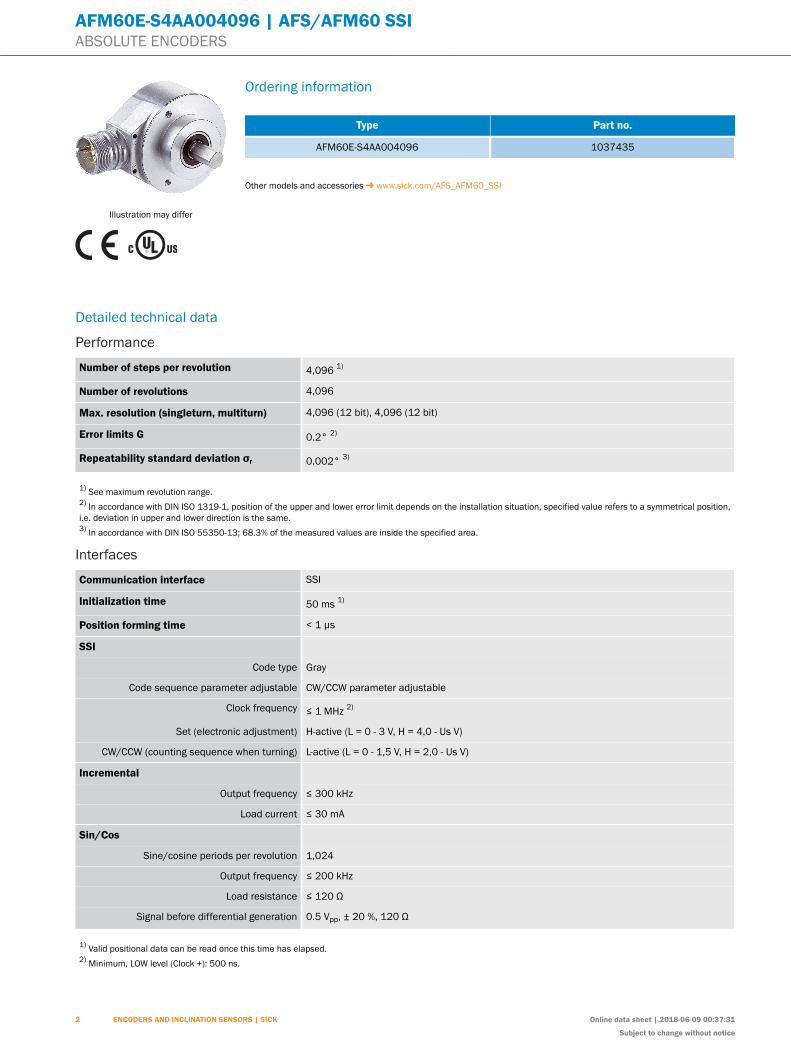
Illustration may differ
Ordering information
Type Part no.
AFM60E-S4AA004096 1037435
Other models and accessories www.sick.com/AFS_AFM60_SSI
Detailed technical data
Performance
Number of steps per revolution 4,096 1)
Number of revolutions 4,096
Max. resolution (singleturn, multiturn) 4,096 (12 bit), 4,096 (12 bit)
Error limits G 0.2° 2)
Repeatability standard deviation σr 0.002° 3)
1) See maximum revolution range.2) In accordance with DIN ISO 1319-1, position of the upper and lower error limit depends on the installation situation, specified value refers to a symmetrical position,i.e. deviation in upper and lower direction is the same.3) In accordance with DIN ISO 55350-13; 68.3% of the measured values are inside the specified area.
Interfaces
Communication interface SSI
Initialization time 50 ms 1)
Position forming time < 1 µs
SSI
Code type Gray
Code sequence parameter adjustable CW/CCW parameter adjustable
Clock frequency ≤ 1 MHz 2)
Set (electronic adjustment) H-active (L = 0 - 3 V, H = 4,0 - Us V)
CW/CCW (counting sequence when turning) L-active (L = 0 - 1,5 V, H = 2,0 - Us V)
Incremental
Output frequency ≤ 300 kHz
Load current ≤ 30 mA
Sin/Cos
Sine/cosine periods per revolution 1,024
Output frequency ≤ 200 kHz
Load resistance ≤ 120 Ω
Signal before differential generation 0.5 Vpp, ± 20 %, 120 Ω
1) Valid positional data can be read once this time has elapsed.2) Minimum, LOW level (Clock +): 500 ns.
2 ENCODERS AND INCLINATION SENSORS | SICK Online data sheet | 2018-06-09 00:37:31
Subject to change without notice

AFM60E-S4AA004096 | AFS/AFM60 SSIABSOLUTE ENCODERS
Signal offset before differential generation 2.5 V ± 10 %
Signal after differential generation 1 Vpp, ± 20 %
1) Valid positional data can be read once this time has elapsed.2) Minimum, LOW level (Clock +): 500 ns.
Electrical dataConnection type Male connector, M23, 12-pin, radial
Supply voltage range 4.5 V DC ... 32 V DC
Power consumption 0.5 W (without load)
Reverse polarity protection ✔
MTTFd: mean time to dangerous failure 250 years (EN ISO 13849-1) 1)
1) This product is a standard product and does not constitute a safety component as defined in the Machinery Directive. Calculation based on nominal load of com-ponents, average ambient temperature 40°C, frequency of use 8760 h/a. All electronic failures are considered hazardous. For more information, see document no.8015532.
Mechanical dataMechanical version Solid shaft, face mount flange
Shaft diameter 10 mm x 19 mm
Shaft length 19 mm
Weight 0.3 kg 1)
Shaft material Stainless steel
Flange material Aluminum
Housing material Aluminum die cast
Start up torque < 0.5 Ncm 2)
Operating torque < 0.3 Ncm 2)
Permissible movement static ± 0.5 mm (axial)± 0.3 mm (radial)
Permissible movement dynamic ± 0.2 mm (axial)± 0.1 mm (radial)
Permissible Load capacity of shaft 80 N / radial40 N / axial
Moment of inertia of the rotor 6.2 gcm²
Bearing lifetime 3.0 x 10^9 revolutions
Angular acceleration + 500,000 rad/s²
Operating speed ≤ 9,000 min⁻¹
1) Relates to devices with male connector connection.2) At 20 °C.
Ambient dataEMC According to EN 61000-6-2 and EN 61000-6-3 1)
Enclosure rating IP65, shaft side (according to IEC 60529)IP67, housing side (according to IEC 60529) 2)
Permissible relative humidity 90 % (condensation of the optical scanning not permitted)
Operating temperature range 0 °C ... +85 °C
1) EMC according to the standards quoted is achieved if shielded cables are used.2) With mating connector fitted.
2018-06-09 00:37:31 | Online data sheet
Subject to change without notice
ENCODERS AND INCLINATION SENSORS | SICK 3

ABCDEF
HIJKLMNOPQRST
AFM60E-S4AA004096 | AFS/AFM60 SSIABSOLUTE ENCODERS
Storage temperature range –40 °C ... +100 °C, without package
Resistance to shocks 50 g, 6 ms (according to EN 60068-2-27)
Resistance to vibration 20 g, 10 Hz ... 2,000 Hz (according to EN 60068-2-6)
1) EMC according to the standards quoted is achieved if shielded cables are used.2) With mating connector fitted.
Classifications
ECl@ss 5.0 27270502
ECl@ss 5.1.4 27270502
ECl@ss 6.0 27270590
ECl@ss 6.2 27270590
ECl@ss 7.0 27270502
ECl@ss 8.0 27270502
ECl@ss 8.1 27270502
ECl@ss 9.0 27270502
ETIM 5.0 EC001486
ETIM 6.0 EC001486
UNSPSC 16.0901 41112113
Dimensional drawing (Dimensions in mm (inch))
Face mount flange, radial plug connection M12 and M23
7.75(0.31)
M23 x 1
26
.1(1
.03
)
13(0.51)
Ø 0.05 B
Ø 3
6(1
.42
) f8
Ø 1
0(0
.39
) f7
0.03 A
B
C
9(0
.35
)
Ø 6
0 (
2.3
6)
40.1 (1.58)
10 (0.39)
A
0.1 A
14
.5(0
.57
)
M12 x 1
(3x)
120°
3 x
M4
(6-d
ee
p)
Ø 4
8±
0.0
5 (
1.8
9)
Ø 0.1 C
18(0.71)
19±0.3
(0.75)
25°±2°
A
General tolerances according to DIN ISO 2768-mk
4 ENCODERS AND INCLINATION SENSORS | SICK Online data sheet | 2018-06-09 00:37:31
Subject to change without notice

AFM60E-S4AA004096 | AFS/AFM60 SSIABSOLUTE ENCODERS
PIN assignmentView of the M23 male connector plug-in face
Connector M23, 12-pin
SSI/Gray
Pin Signal Explanation
1 GND Ground connection
2 Data+ Interface signals
3 Clock+ Interface signals
4 N. C. Not connected
5 N. C. Not connected
6 N. C. Not connected
7 N. C. Not connected
8 US
Supply voltage
9 SET Electronic adjustment
10 Data– Interface signals
11 Clock– Interface signals
12 CW/CCW Counting sequence when turning
Screen Screen on the encoder side connected to the housing. On the control side connected to earth.
Connector M23, 12-pin and cable outlet, cable 12-core
SSI/Gray + Incremental
Pin Color wires Signal Explanation
1 Red +US
Supply voltage
2 Blue GND Ground connection
3 Yellow Clock+ Interface signal
4 White Data+ Interface signal
5 Orange SET Electronic adjustment
6 Brown Data– Interface signal
7 Violet Clock– Interface signal
8 Black ¯ B Signal line
9 Orange/black CW/CCW Counting sequence when turning
10 Green ¯A Signal line
11 Gray A Signal line
12 Pink B Signal line
Screen Screen on the encoder side connected to the housing. On the control side connected to earth.
Connector M23, 12-pin and cable outlet, cable 12-core
SSI/Gray + Sin/Cos
Pin Color wires Signal Explanation
1 Red +US
Supply voltage
2 Blue GND Ground connection
3 Yellow Clock+ Interface signal
4 White Data+ Interface signal
5 Orange SET Electronic adjustment
6 Brown Data– Interface signal
7 Violet Clock– Interface signal
8 Black Sin– Signal line
9 Orange/black CW/CCW Counting sequence when turning
10 Green Cos– Signal line
11 Gray Cos+ Signal line
12 Pink Sin+ Signal line
Screen Screen on the encoder side connected to the housing. On the control side connected to earth.
2018-06-09 00:37:31 | Online data sheet
Subject to change without notice
ENCODERS AND INCLINATION SENSORS | SICK 5

ABCDEF
HIJKLMNOPQRST
AFM60E-S4AA004096 | AFS/AFM60 SSIABSOLUTE ENCODERS
Maximum revolution range
The maximum speed is also dependent on the shaft type.
6 ENCODERS AND INCLINATION SENSORS | SICK Online data sheet | 2018-06-09 00:37:31
Subject to change without notice
AFM60E-S4AA004096 | AFS/AFM60 SSIABSOLUTE ENCODERS
Diagrams
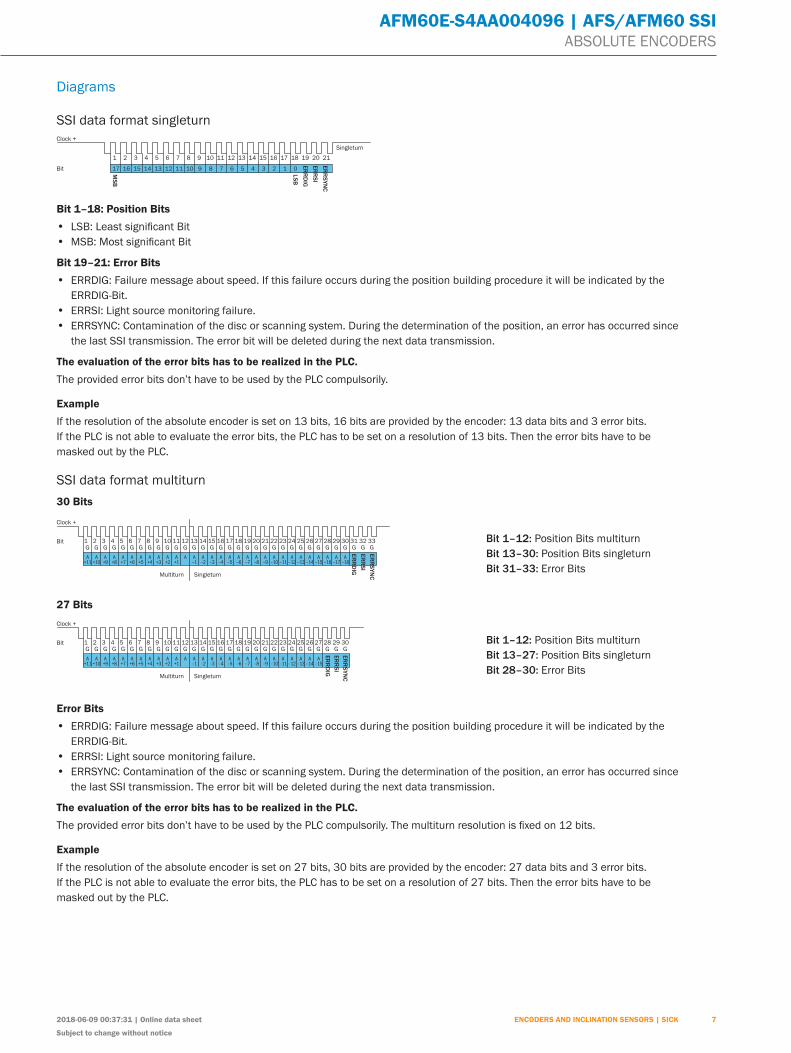
SSI data format singleturn
Clock +
Bit
Singleturn
1 2 3 4 5 6 7 8 9 10 11 12 13 14 15 16 17 18 19 20 21
17 16 15 14 13 12 11 10 9 8 7 6 5 4 3 2 1 0
MS
B
LS
B
ER
RD
IG
ER
RS
I
ER
RS
YN
C
Bit 1–18: Position Bits
•
•
Bit 19–21: Error Bits
• ERRDIG: Failure message about speed. If this failure occurs during the position building procedure it will be indicated by the
ERRDIG-Bit.
• ERRSI: Light source monitoring failure.
• ERRSYNC: Contamination of the disc or scanning system. During the determination of the position, an error has occurred since
the last SSI transmission. The error bit will be deleted during the next data transmission.
The evaluation of the error bits has to be realized in the PLC.
The provided error bits don’t have to be used by the PLC compulsorily.
Example
If the resolution of the absolute encoder is set on 13 bits, 16 bits are provided by the encoder: 13 data bits and 3 error bits.
If the PLC is not able to evaluate the error bits, the PLC has to be set on a resolution of 13 bits. Then the error bits have to be
masked out by the PLC.
SSI data format multiturn
30 Bits
Clock +
Bit
SingleturnMultiturn
1G G G G G G G G G G G G G G G G G G G G G G G G G G G G G G G GG
2 3 4 5 6 7 8 9 10 11 12 13 14 15 16 17 18 19 20 21 22 23 24 25 26 27 28 29 30 31 32 33
AA
+1
A
–1
A
–2
A
–3
A
–4
A
–5
A
–6
A
–7
A
–8
A
–9
A
–10
A
–11
A
–12
A
–13
A
–14
A
–15
A
–16
A
–17
A
–18
A
+2
A
+3
A
+4
A
+5
A
+6
A
+7
A
+8
A
+9
A
+10
A
+11
ER
RD
IG
ER
RS
I
ER
RS
YN
C
Bit 1–12: Position Bits multiturn
Bit 13–30: Position Bits singleturn
Bit 31–33: Error Bits
27 Bits
Clock +
Bit
SingleturnMultiturn
1G G G G G G G G G G G G G G G G G G G G G G G G G G G G G G
2 3 4 5 6 7 8 9 10 11 12 13 14 15 16 17 18 19 20 21 22 23 24 25 26 27 28 29 30
AA
+1
A
–1
A
–2
A
–3
A
–4
A
–5
A
–6
A
–7
A
–8
A
–9
A
–10
A
–11
A
–12
A
–13
A
–14
A
–15
A
+2
A
+3
A
+4
A
+5
A
+6
A
+7
A
+8
A
+9
A
+10
A
+11
ER
RD
IG
ER
RS
I
ER
RS
YN
C
Bit 1–12: Position Bits multiturn
Bit 13–27: Position Bits singleturn
Bit 28–30: Error Bits
Error Bits
• ERRDIG: Failure message about speed. If this failure occurs during the position building procedure it will be indicated by the
ERRDIG-Bit.
• ERRSI: Light source monitoring failure.
• ERRSYNC: Contamination of the disc or scanning system. During the determination of the position, an error has occurred since
the last SSI transmission. The error bit will be deleted during the next data transmission.
The evaluation of the error bits has to be realized in the PLC.
Example
If the resolution of the absolute encoder is set on 27 bits, 30 bits are provided by the encoder: 27 data bits and 3 error bits.
If the PLC is not able to evaluate the error bits, the PLC has to be set on a resolution of 27 bits. Then the error bits have to be
masked out by the PLC.
2018-06-09 00:37:31 | Online data sheet
Subject to change without notice
ENCODERS AND INCLINATION SENSORS | SICK 7

ABCDEF
HIJKLMNOPQRST
AFM60E-S4AA004096 | AFS/AFM60 SSIABSOLUTE ENCODERS
Electrical interfaces sine 0.5 Vpp
Power supply Output
4.5 ... 5.5 V Sine 0.5 Vpp
Signal before differential generation at load 120 Ω at US = 5 V
Signal diagram for clockwise rotation of the shaft looking in direction “A” (shaft)
2.5 V
2.5 V
0.5 V
0.5 V
360° el.
90° el. COS+ COS–
SIN+ SIN–
soC ,soC ,niS ,niS slangis ecafretnI Signal before differential generation at load 120 Ω Signal offset
Analog differential 0.5 Vpp
± 20 % 2.5 V ± 10 %
Signal after differential generation at load 120 Ω at US = 5 V
Signal diagram for clockwise rotation of the shaft looking in direction “A” (shaft)
COS+ ... COS–
SIN+ ... SIN–
0 V
0 V
1 V
1 V
360° el.
90° el.
Incremental pulse diagram for clockwise rotation of the shaft looking in direction “A”, see dimensional drawing
Measuring step
A
A
B
B
90° el.
360° el.
Electrical interfaces HTL/TTL
8 ENCODERS AND INCLINATION SENSORS | SICK Online data sheet | 2018-06-09 00:37:31
Subject to change without notice
AFM60E-S4AA004096 | AFS/AFM60 SSIABSOLUTE ENCODERS
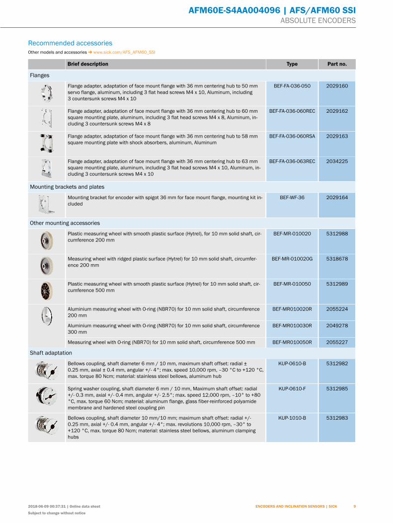
Recommended accessoriesOther models and accessories www.sick.com/AFS_AFM60_SSI
Brief description Type Part no.
Flanges
Flange adapter, adaptation of face mount flange with 36 mm centering hub to 50 mmservo flange, aluminum, including 3 flat head screws M4 x 10, Aluminum, including3 countersunk screws M4 x 10
BEF-FA-036-050 2029160
Flange adapter, adaptation of face mount flange with 36 mm centering hub to 60 mmsquare mounting plate, aluminum, including 3 flat head screws M4 x 8, Aluminum, in-cluding 3 countersunk screws M4 x 8
BEF-FA-036-060REC 2029162
Flange adapter, adaptation of face mount flange with 36 mm centering hub to 58 mmsquare mounting plate with shock absorbers, aluminum, Aluminum
BEF-FA-036-060RSA 2029163
Flange adapter, adaptation of face mount flange with 36 mm centering hub to 63 mmsquare mounting plate, aluminum, including 3 flat head screws M4 x 10, Aluminum, in-cluding 3 countersunk screws M4 x 10
BEF-FA-036-063REC 2034225
Mounting brackets and plates
Mounting bracket for encoder with spigot 36 mm for face mount flange, mounting kit in-cluded
BEF-WF-36 2029164
Other mounting accessories
Plastic measuring wheel with smooth plastic surface (Hytrel), for 10 mm solid shaft, cir-cumference 200 mm
BEF-MR-010020 5312988
Measuring wheel with ridged plastic surface (Hytrel) for 10 mm solid shaft, circumfer-ence 200 mm
BEF-MR-010020G 5318678
Plastic measuring wheel with smooth plastic surface (Hytrel) for 10 mm solid shaft, cir-cumference 500 mm
BEF-MR-010050 5312989
Aluminium measuring wheel with O-ring (NBR70) for 10 mm solid shaft, circumference200 mm
BEF-MR010020R 2055224
Aluminium measuring wheel with O-ring (NBR70) for 10 mm solid shaft, circumference300 mm
BEF-MR010030R 2049278
Measuring wheel with O-ring (NBR70) for 10 mm solid shaft, circumference 500 mm BEF-MR010050R 2055227
Shaft adaptation
Bellows coupling, shaft diameter 6 mm / 10 mm, maximum shaft offset: radial ±0.25 mm, axial ± 0.4 mm, angular +/- 4°; max. speed 10,000 rpm, –30 °C to +120 °C,max. torque 80 Ncm; material: stainless steel bellows, aluminum hub
KUP-0610-B 5312982
Spring washer coupling, shaft diameter 6 mm / 10 mm, Maximum shaft offset: radial+/- 0.3 mm, axial +/- 0.4 mm, angular +/- 2.5°; max. speed 12,000 rpm, –10° to +80°C, max. torque 60 Ncm; material: aluminum flange, glass fiber-reinforced polyamidemembrane and hardened steel coupling pin
KUP-0610-F 5312985
Bellows coupling, shaft diameter 10 mm/10 mm; maximum shaft offset: radial +/-0.25 mm, axial +/- 0.4 mm, angular +/- 4°; max. revolutions 10,000 rpm, –30° to+120 °C, max. torque 80 Ncm; material: stainless steel bellows, aluminum clampinghubs
KUP-1010-B 5312983
2018-06-09 00:37:31 | Online data sheet
Subject to change without notice
ENCODERS AND INCLINATION SENSORS | SICK 9

Onlin
e da
ta s
heet
SICK AG | Waldkirch | Germany | www.sick.com
SICK At A GlAnCeSICK is one of the leading manufacturers of intelligent sensors and sensor solutions for industrial applica-tions. A unique range of products and services creates the perfect basis for controlling processes securely and efficiently, protecting individuals from accidents and preventing damage to the environment.
We have extensive experience in a wide range of industries and understand their processes and require-ments. With intelligent sensors, we can deliver exactly what our customers need. In application centers in Europe, Asia and North America, system solutions are tested and optimized in accordance with customer specifications. All this makes us a reliable supplier and development partner.
Comprehensive services complete our offering: SICK lifetime Services provide support throughout the ma-chine life cycle and ensure safety and productivity.
For us, that is “Sensor Intelligence.”
WOrldWIde preSenCe:Contacts and other locations – www.sick.com