


AFRICAN FUSION NOVEMBER 2014 Journal of the … 2014 Journal of the Southern African Institute of...
48
AFRICAN FUSION Journal of the Southern African Institute of Welding NOVEMBER 2014
Transcript of AFRICAN FUSION NOVEMBER 2014 Journal of the … 2014 Journal of the Southern African Institute of...

AFRIC
ANFUSIONJournal of the Southern African Institute of WeldingNOVEMBER 2014

November 2014 AFRICAN FUSION 1
Published four times a year and mailed out together with Mechanical Technology by:
Crown Publications cc
Crown HouseCnr Theunis and Sovereign StreetsBedford Gardens 2007PO Box 140Bedfordview 2008
Tel: (011) 622 4770Fax: (011) 615 6108
Editor: Peter MiddletonE-mail: [email protected]
Advertising: Norman WelthagenE-mail: [email protected]
Publisher: Karen Grant
Managing member: Jenny Warwick
Cover design: Air Liquide
Production & layout: Gail Smith
Circulation: Karen Pearson
Subscriptions: Wendy Charles
Printed by: Tandym Print
November 2014Contents
REGULARS3 Jim’s comment7 SAIW bulletin board 14 Front cover story: ARCAL New Generation shielding gases
and supply modes36 Welding and cutting forum44 Ni-Cu cladding using basic flux-cored wirewww.crown.co.za
32
30
8
FEATURES
4 SAIW seminars clarify EN 15085 On 28 and 29 October, in Johannesburg and Durban
respectively, SAIW hosted Albrecht Hans from the Ger-man Welding Society (DVS) for a series of seminars on EN 15085, the international standard for the welding of railway vehicles and components.
7 Young welder 2015 African Fusion talks to Houston Isaacs, the 2013 winner
and 2010 runner up of the SAIW’s Young Welder of the Year competition.
8 Wits installs Gleeble materials testing facility The University of the Witwatersrand’s School of
Chemical and Metallurgical Engineering has commis-sioned a R13.5-million Gleeble thermal-mechanical simulation facility.
16 Dealing with materials and welding quality on Eskom’s new-build plants
This paper by Prince NSP Dlamini was awarded the SAIW’s 2014 Harvey Shacklock Gold Medal. Through case studies, Dlamini highlights some of the technical challenges associated with the materials, welding and weld quality for the new-build power stations.
26 Welding consumables and procedures for the en-ergy sector: Part 1:
V van der Mee of Lincoln Electric, Europe, deals with welding consumables for the modern power sector in this two-part paper. Part 1 deals with the modified 9%CrMo steels (P/T91) and their variants, such as P92 and E911.
30 Raising the pipe-welding productivity bar Afrox’s PipeWorx is an advanced multi-process pipe
welding solution from Miller Electric. African Fusion talks to Johan Pieterse and Tshidiso Seleka.
32 New martensitic 9-12% Cr steels and filler metals voestalpine Böhler Welding introduces new high-
temperature creep-resistant steels for use in thermal power plants and describes the consumables and heat treatment processes required for welding.
34 Automatic measuring for welded components Made possible by a Motoman robot from Yaskawa,
equipped with a stereo camera head, this article describes a fully automatic system from Ziemann & Urban for measuring and leak testing welded exhaust systems.
Air Liquide officially launched its ARCALTM New Generation range of shielding gases into the South African market at the 2014 Electra Mining Africa show. African Fusion visits the stand and talks to Rolf Schluep and Rob Lawrence about the company’s drive towards sim-plifying the shielding gas of-fering, while maintaining the highest levels of weld quality.
36

November 2014 AFRICAN FUSION 3
SAIW and SAIW Certification
SAIW PresidentM Maroga - SAIW PresidentCouncil membersJR Williamson - Personal memberT Rice - Personal memberDJ Olivier - Personal memberW Rankin - Personal memberP Viljoen - PEMAA Koursaris - Personal memberF Buys - TÜVG Joubert - SAISIJ Pieterse - AfroxJ Zinyana - Personal memberL Breckenridge - CEAA Paterson - University of the WitwatersrandW Scurr - SASSDAJ Botha - SAISI
Technology and Training Board P Venter - Chairperson, ArcelorMittal
SAIW Certification Governing Board G Joubert - Chairperson, ArcelorMittalA Koursaris - SAIWF Buys - SAQCC IPEJ Guild - SAIWD Olivier - SAQCC CPR Williamson - Consultant/Service IndustryP Viljoen - Fabricator’s BoardW Rankin - VelosiJ Zinyana - New Age Welding SolutionsP Bruwer - Sasol SynfuelsM Moraga - EskomS Moodly - SAPREFB Beetge - Sentinel Inspection
Executive directorJC GuildTel: (011) 298-2101Fax: (011) [email protected]
Executive secretaryD KreouziTel: (011) 298-2102Fax: (011) [email protected]
General manager,operationsS BlakeTel: (011) 298-2103Fax: (011) [email protected]
SAIW and SAIW Certification representativesQualification and certifica-tion managerH PotgieterTel: (011) [email protected]
Technical services and training managerS BlakeTel: (011) 298-2103Fax: (011) [email protected]
Finance and administra-tion managerM WarmbackTel: (011) 298-2125Fax: (011) [email protected]
Western Cape representativeL BerryTel: (021) 555-2535Fax: (021) 555-2517 [email protected]
SAIW regional representatives
KZN representativeA MeyerTel: 083 [email protected]
SAIW: Jim's comment
November 2014 AFRICAN FUSION 3
Jim Guild
There is no doubt that 2014 has been a chal-lenging year in South
Africa, for the Institute and for all businesses in the country. The root cause of this is the lack of economic growth, which creates an environment in which no jobs are created, no new major contracts are awarded and no significant investments are made.
The key to a solution to the growth problem is to get the National Development Plan (NDP) going! This is an excellent overall infrastruc-tural development plan but what is missing is the implementation. Encouraging private industry to invest in the NDP would help but gov-ernment policies are not favourable to industry. An economic CODESA, which has been mooted by a number of political commentators, may be a useful tool in this process. For the sake of all South Africans, I call on both parties to sit together and work things out in a mature and responsible way in order to unleash the enormous potential this country has.
From the Institute’s perspective, although trading conditions have been tough, I think we can look back on 2014 with great pride. Anyone who was at the Awards and Certification dinners will have an inkling of what this Institute is all about – young vibrant people doing all they can to improve their lives through study and education and older people using improved qualifications to enhance career opportunities.
It is always a moving experience to see the hundreds of gradu-ates proudly receiving their certificates and also to be able to honour those who have given a lifetime of service to the Institute and the welding industry. In this regard I would like to single out Lorraine Lerato Montsho who, for a second time, won the honour of the best NDT student and also Robin Williamson, an ex-President of the SAIW who has given 30 years of selfless service to the Institute, for which he was awarded the SAIW Gold Medal. Both are wonderful examples of what we are all about!
One of our key activities as an Institute is managing the Young Welder of the Year competition. I say ‘managing’ because there is no doubt that this is an industry initiative and could not happen without the full participation of so many people and companies in the indus-try. I am pleased to report that the 2015 competition currently has 10 confirmed entrants with 20 more being assessed to compete in the finals in January 2015.
One of the most important Institute initiatives this year was the expansion of our footprint to Cape Town where we recently officially opened new premises in Milnerton. We are also looking for premises in Durban and Mpumalanga to house the appropriate training and administrative facilities required by an SAIW branch. This expansion is not only a sign of the current success of the SAIW but also of our optimism for the future.
Finally, I wish you all a peaceful and safe festive season and I look forward to another great year for the Institute and for South Africa as a whole.

44 AFRICAN FUSION November 2014
SAIW: EN 15085 seminars
A safe rail transport system cannot be guaranteed without adhering to high quality standards, and
welding is a critical process whose qual-ity cannot be determined by inspection after manufacture. Welding and joining processes, therefore, in particular on load bearing structures of railway ve-hicles, require special attention.
In Europe, most manufacturers of railway vehicles or components need to be certified in accordance with BS EN 15085: 2007: Railway applications. Welding of railway vehicles and com-ponents. While not yet a South African requirement, European and Chinese OEMs such as Bombardier and China South Rail (CSR), are likely to make EN 15085 a requirement for any equip-ment sub-contracted to South African
SAIW seminars clarifyEN 15085 railway requirementsOn 28 and 29 October, in Johannesburg and Durban respectively, SAIW-hosted Albrecht Hans from the German Welding Society (DVS) for a series of seminars on EN 15085, the Eu-ropean standard for the welding of railway vehicles and components.
manufacturers. In order to clarify
the requirements and explain the advantages of EN 15085, the SAIW invited Albrecht Hans to come to South Africa during October. Hans has worked as a welding engineer in the railway and automotive sectors for many years and has been with DVS for the past 23 years, dealing with the implementation of welding engineering standards, including ISO 3834 and EN 15085. He is currently deputy head of DVS’ Manufacturer Certification Body for EN 15085 in Duisburg.
In introducing the EN 15085 stan-dard, Hans says that “welding is a
special process in the manufacture of railway vehicles and their parts” and that the required provisions for this process (that is, the welding process) are laid down in EN ISO 3834: Quality requirements for fusion welding of metal-lic materials. ISO 3834, therefore, forms the basis, from a welding point of view, of the EN 15085 standard.
Describing the essential difference between ISO 3834 and EN 15085, SAIW general manager Sean Blake says: “In essence, ISO 3834 is a general welding quality standard, while EN 15085 is a product standard that details spe-cific requirements for railway vehicles and components. But compliance to ISO 3834 is an integral requirement of EN 15085 certification. The SAIW, there-fore, sees ISO 3834 as the logical starting point for vehicle manufacturers seeking certification to EN 15085,” he adds.
SAIW has entered into an agreement with DVS to act as a pre-certification consultant for railway vehicle manufac-turers in South Africa. “We see a three-step process to EN 15085 certification. First, manufacturers need to join the SAIW Welding Fabricator’s Certification Scheme and obtain ISO 3834 certifica-tion. Then, once their welding process quality system is in place, SAIW is in position to offer consultancy services
Albrecht Hans from the German Welding Society (DVS) presents the SAIW-hosted EN 15085 seminar.
A select group of South African Railway manufacturers attend the SAIW-hosted Albrecht Hans seminar.

5
SAIW: EN 15085 seminars
5November 2014 AFRICAN FUSION
in preparation for the implementation of the special requirements of EN 15085. In particular, these involve aligning all the specific welding, manufacturing and quality codes to ISO or European standards.
“Final EN 15085 certification, how-ever, needs to be done directly by DVS auditors from Duisberg. It will, therefore, be more sensible and cost effective for railway manufacturers to be well pre-pared, so that the audits are quick and certification is successful on the first attempt,” Blake suggests.
Notes from Hans’ seminarIntroducing EN 15085, Hans says that the series of standards applies to welding of metallic materials in the manufacture and maintenance of railway vehicles and their parts. It therefore applies to both new-build and repaired components, welded in steel and aluminium alloys, including castings. All assemblies, sub-assemblies or parts welded by any welding process – manual, partly mechanised, fully mechanised or us-ing automatic processes – fall into the standard’s scope.
“Generally, customers prescribe performances applicable to finished products; they do not prescribe welding methods,” says Hans. “The manufacturer thus has full freedom to select whichever welding process, consumables and joint preparation they wish to implement. In return, upon customer request, the manufacturer shall demonstrate that it has full control and that the quality level requested by customers will be achieved, in particular through: company certi-fication; welder and welding operator qualifications; and welding process and mock-up qualifications,” he notes.
In direct alignment with ISO 3834, certification according EN 15085 can be awarded at four different certifica-tion levels (CLs): To be granted CL 1 certification, the manufacturer has to comply with EN ISO 3834-2, that is, the comprehensive quality requirements of ISO 3834. CL 1 applies to manufacturers of welded railway vehicles or their weld-ed parts with welded joints classified at the highest performance level, CP A. It also enables them to manufacture all parts in lower performance classes, CP B to CP D.
The CP A performance classification incorporates all safety-relevant parts: buffers and draw gear; wheel set compo-nents (wheel set mountings, axle boxes,
or the welding co-ordinator needs expe-rience of welding supervision and proof of basic technical knowledge.
“SAIW is well placed to assist manu-facturers to meet the requirements of EN 15085. The certification and qualifi-cation programmes are in place. All we need is more experience with respect to actual implementation,” says Blake.
“In the pressure equipment and structural fields in South Africa, we have a number of people with the skills to implement EN 15085, but I am concerned that the skills, experience and knowledge required for EN 15085 certification is not as evident among the current railway manufacturing frater-nity – and some of these requirements exceed those for pressure vessels.
“The danger is that overseas OEMs will renege on their local manufacturing commitments if South African manufac-turers cannot satisfy the quality require-ments. We must be proactive about EN 15085 to make sure that this cannot happen,” Blake concludes.
The first SA95NEL electric freight locomotive ordered by Transnet leaves CSR’s Zhuzhou Electric Locomotive’s factory in China. The first 10 are to be produced in China, with the remaining 85 to be assembled at Koedoespoort, South Africa.
240 Bombardier Traxx Africa dual-voltage electric locomotives have been ordered by Transnet Freight Rail (TFR), many of which will be manufactured locally by Transnet Engineering in Durban.
spring supports); brake equipment (magnet-ic track brake, brake rods, brake triangles, brake cylinders, brake cross beams); support-ing frames for heavy components (traction units, pantographs); welded transmission components between the bogie and the vehi-cle; vibration dampers; and any finish welding on castings for CP A listed components.
There are three fur-ther performance clas-sification levels, CP B to CP D, to cover decreas-ing levels of component performance.
Certification level 2 (CL 2) requires ISO 3834 Part 3 (standard quality level) conformity and aligns with the CP B performance level , while EN 15085 CL 3 embraces non-critical component perfor-mance (CP C) and re-quires elementary level ISO 3834-4 weld quality conformity. “CL 4 ap-plies to manufacturers that do not, themselves, do welding: designers of railway vehicles and parts, for example, or traders that assemble and sell components,” Hans points out.
In terms of welding personnel, very specific welding qualification require-ments are specified in EN 15085 for the different certification levels. For manufacturers of CP A components to be certified to CL 1, a welding supervi-sor qualified as an International Weld-ing Engineer or Welding Technologist (IWE/IWT), or a welding co-ordinator with proven comprehensive technical knowledge and three years of experi-ence, must be available to supervise welding activities.
For CL 2-level certification an In-ternational Welding Technologist or International Welding Supervisor (IWT/IWS), or a welding co-ordinator with specifically relevant experience and knowledge has to be on hand, while for CL 3 certification, welding supervisors need to be qualified to specialist or to IIW welding practitioner level (IWS/IWP)

SAIW: Young welder of the year, 2015
7November 2014 AFRICAN FUSION
The 2015 Young Welder of the Year competition has received unprec-edented interest from all over the
country. This is has become the foremost skills test for young welders in South Africa. The winner will represent South Africa at the WorldSkills competition to be held in Sao Paulo, Brazil, from 11-16 August 2015. The sponsors for the 2015 competition so far are: Abicor Binzel, Afrox, AFSA, Air Products, ArcelorMit-tal, ESAB, Hulamin, Merseta, SASSDA, Thuthuka Welding and WASA.
Jim Guild, executive director of the Southern African Institute of Welding (SAIW), says that the Young Welder competition is an industry initiative and would not survive without its sponsors. “We are all grateful that the sponsors understand the growing importance of this competition in terms of encouraging welding as an exciting and sustainable career for our youth. There is always room for more sponsors and those in-terested should contact the Institute.”
SAIW GM Operations, Sean Blake, says he is delighted with the enthusi-asm of the entire industry including both TVET Colleges like College of Cape Town and a company artisan training school – Steinmüller. “The increased involvement of those who are teaching the youth welding skills is most encour-aging and with their support we will be extending the footprint of the competi-tion quite considerably,” Blake says. “We are particularly pleased that Steinmüller has opted to be on the organising com-mittee and we look forward to working with them.”
In terms of the extended footprint Blake says that regional competitions are being held in November in the Western Cape, KZN and Mpumalanga. “This will give a lot more youngsters the chance to get into the finals in Johan-nesburg and will, of course, substantially increase awareness of the Young Welder
The SAIW 2015 Young Welder of the Year competition will be held from 26-30 January at SAIW’s Johannesburg West premises. African Fusion talks to Houston Isaacs, the 2013 winner and 2010 runner up.
Young welder 2015 –Creating employment and skilling our youth
Houston Isaacs, 2013 Young Welder of the Year winner with SAIW’s Etienne Nell (centre) and Frans Vorster (right).
competition,” Blake says. “Using the theme ‘Creating Employ-
ment: Skilling our Youth’ we plan to get wide coverage of the competition in the classical media like radio, print and television. We will also be making a special video CD of the competition, which will be used as a promotional tool,” says Blake.
All young welders in South Africa, who will not be more than 22 years of age on December 31, 2014, are invited to enter the competition.
Entrants will have to show that they have mastered four welding processes – shielded metal arc welding (SMAW), gas tungsten arc welding (GTAW), gas metal arc welding (GMAW) and flux-cored arc welding (FCAW) – across the three mate-rials or in their chosen material.
Houston Isaacs’ experienceHouston Isaacs began his welding career at the West Coast FET College, Vreden-burg campus, near Saldana. “I was en-tered into the 2010 Young Welder of the Year competition by my project manager at the college, Thembinkosi Matyeka, who also won the competition back in 2005. That was my first time in the ‘big city’ and in that year, I won the stainless steel and aluminium categories and was the overall runner-up. “After that, I went back to Saldanha, where I worked for Saldana steel for a few months, before being approached by Johan Pieterse to join Afrox,” Isaacs tells African Fusion.
He started at Afrox as a trainee in February 2011 and was enrolled on the International Welding Specialist (IWS) course at the SAIW, which took the whole year. “While with Afrox, I qualified as a Red Seal artisan at the Afrojap welding skills centre in Witbank,” he adds.
In January 2013, Isaacs was entered into the 2013 Young Welder of the Year competition “I was the only person who had previously entered, so I was very
calm and knew exactly what to expect,” he notes. Isaacs won in every category that year, carbon steel, stainless steel and aluminium, and emerged as the most emphatic winner in the competi-tion’s history.
He then spent a further six months training at the Institute for the World Skills Competition held in Leipsig, Ger-many in July of 2013. ”The competition was huge. It was amazing to see all of the different trades and the artisans involved from so many places around the world,” Isaacs recalls.
“WorldSkills is harder than YWoY, “Here we know each other and way things work, but there, you see people from all over the world and hear lots of different languages and the only person you can understand is your expert. And some of the competitors produce welds that could have been done by robots. They are amazing and I am not sure how they get it right,” Isaacs relates.
Isaacs ended the International con-test just a few points short of a Medal of excellence. But as Afrox’s Johan Pieterse points out: “At the age of 23, Houston is now a Red Seal Artisan, a qualified in-ternational welding specialist, qualified international welding instructor, quali-fied international welder and a valuable member of Afrox’s welding applications and development team.
“All because his skills were noticed at a Young Welder of the Year Contest,” Pieterse concludes.
8 AFRICAN FUSION November 20148
SAIW: Wit’s Gleeble testing facility
The Gleeble was originally de-signed for welding research in the early 1960s. “The unique charac-
teristics of the weld heat-affected zone (HAZ) – and the very limited understand-ing of the metallurgy of welding process-es at that time – required a method to generate large numbers of samples with specific microstructures,” says Paterson. Since that time, the Gleeble’s capability and use has extended to the simulation of many manufacturing processes that involve the combination of stress, strain and heating/cooling cycles.
“When two pieces of metal are welded together, steep temperature gra-dients are created. The microstructure of the metal affected by these gradients varies significantly in the zone between the weld itself, where the metal has been melted, and the unaffected wrought base material. This affected region is known as the heat-affected zone, the HAZ,” he explains.
“Within that HAZ there can be areas with brittle or weak microstructures that can create cracks in the material. These cracks, once started, can lead to unan-ticipated failure within the material near the weld, sometimes with catastrophic results,” he adds.
The successful search for stronger materials has led to the design of lighter structures and more highly stressed welds. This increases the tendency for a structure to distort during welding and deflect in service – effects that were previously masked by the material’s thickness.
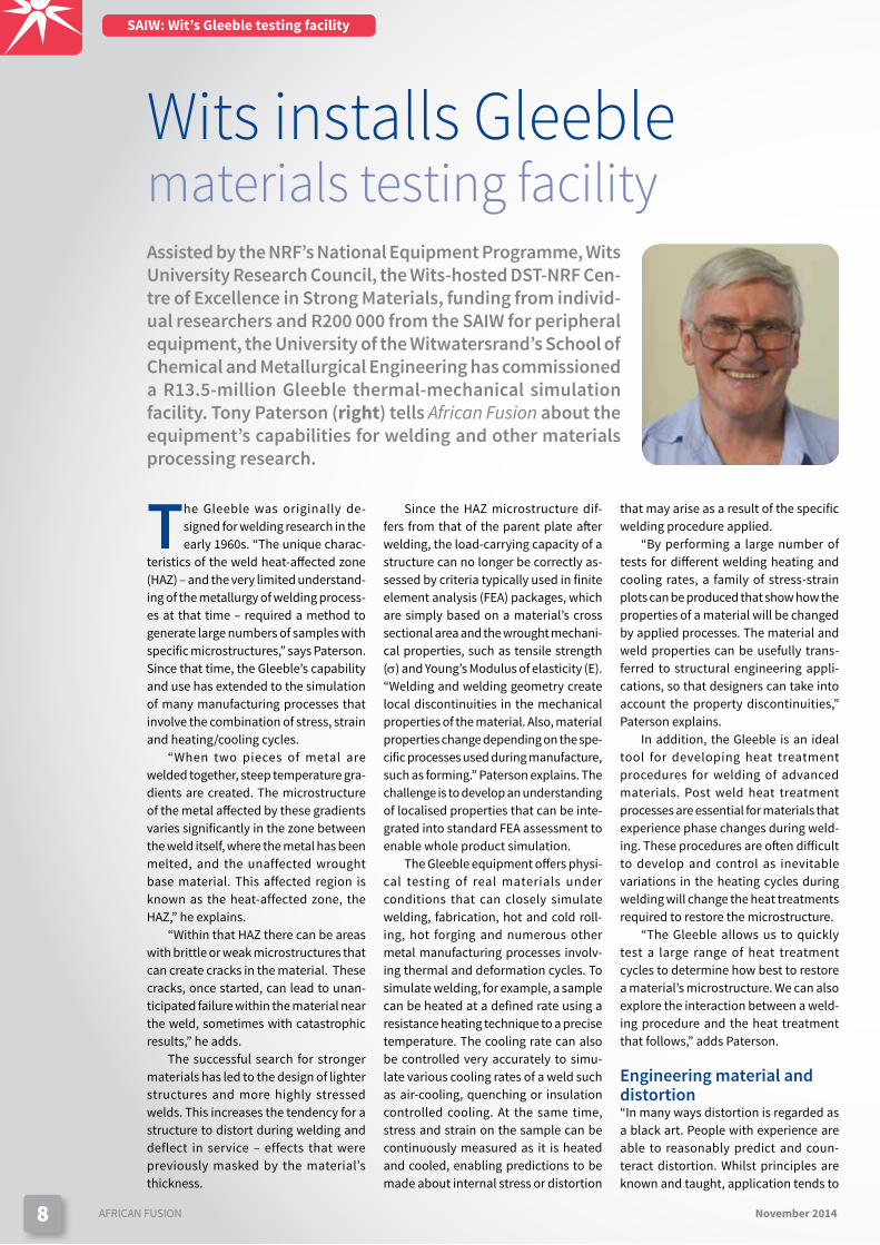
Assisted by the NRF’s National Equipment Programme, Wits University Research Council, the Wits-hosted DST-NRF Cen-tre of Excellence in Strong Materials, funding from individ-ual researchers and R200 000 from the SAIW for peripheral equipment, the University of the Witwatersrand’s School of Chemical and Metallurgical Engineering has commissioned a R13.5-million Gleeble thermal-mechanical simulation facility. Tony Paterson (right) tells African Fusion about the equipment’s capabilities for welding and other materials processing research.
Wits installs Gleeblematerials testing facility
Since the HAZ microstructure dif-fers from that of the parent plate after welding, the load-carrying capacity of a structure can no longer be correctly as-sessed by criteria typically used in finite element analysis (FEA) packages, which are simply based on a material’s cross sectional area and the wrought mechani-cal properties, such as tensile strength (σ) and Young’s Modulus of elasticity (E). “Welding and welding geometry create local discontinuities in the mechanical properties of the material. Also, material properties change depending on the spe-cific processes used during manufacture, such as forming.” Paterson explains. The challenge is to develop an understanding of localised properties that can be inte-grated into standard FEA assessment to enable whole product simulation.
The Gleeble equipment offers physi-cal testing of real materials under conditions that can closely simulate welding, fabrication, hot and cold roll-ing, hot forging and numerous other metal manufacturing processes involv-ing thermal and deformation cycles. To simulate welding, for example, a sample can be heated at a defined rate using a resistance heating technique to a precise temperature. The cooling rate can also be controlled very accurately to simu-late various cooling rates of a weld such as air-cooling, quenching or insulation controlled cooling. At the same time, stress and strain on the sample can be continuously measured as it is heated and cooled, enabling predictions to be made about internal stress or distortion
that may arise as a result of the specific welding procedure applied.
“By performing a large number of tests for different welding heating and cooling rates, a family of stress-strain plots can be produced that show how the properties of a material will be changed by applied processes. The material and weld properties can be usefully trans-ferred to structural engineering appli-cations, so that designers can take into account the property discontinuities,” Paterson explains.
In addition, the Gleeble is an ideal tool for developing heat treatment procedures for welding of advanced materials. Post weld heat treatment processes are essential for materials that experience phase changes during weld-ing. These procedures are often difficult to develop and control as inevitable variations in the heating cycles during welding will change the heat treatments required to restore the microstructure.
“The Gleeble allows us to quickly test a large range of heat treatment cycles to determine how best to restore a material’s microstructure. We can also explore the interaction between a weld-ing procedure and the heat treatment that follows,” adds Paterson.
Engineering material and distortion“In many ways distortion is regarded as a black art. People with experience are able to reasonably predict and coun-teract distortion. Whilst principles are known and taught, application tends to

9November 2014 AFRICAN FUSION 9
be far more difficult.” Paterson suggests. Distortion occurs because of the latent internal stresses resulting from heating or welding processes applied to flat or shaped forms. “Welding acts rather like post tensioning. The contraction stresses associated with cooling cause significant distortion,” he explains.
“The potential use of the Gleeble to develop a science around this craft to assist in decision making and distortion compensation, seems patent,” Paterson advises.
Database developmentThe great advantage of using the Glee-ble’s testing and simulation capability is that each controlled, reproducible test produces one unique HAZ micro-structure. This differs, for instance, from the great variety of microstructures encountered in real welds. A database of different metal compositions, thermal and mechanical treatments and the re-sulting microstructures and associated mechanical properties that arise will be compiled for a number of materials and treatments of interest. However, this database needs to be built up and tested against real specimens. “Creating databases of the different possible HAZ microstructures is the key initial research
task for this department’s Gleeble,” Pat-erson tells African Fusion.
“Lesley Cornish, director of the DST-NRF CoE in Strong Materials, and Lesley Chown, senior lecturer in metallurgy and materials engineering, will then expand the research into alloy development and industrial process optimisation,” he adds.
Structural engineering and finite element analysis FEA programs used for computer simula-tion are based on the assumptions that material properties are homogenous. But, as noted above, any process that includes heating and cooling cycles, or generates local internal stresses, intro-duces discontinuous material properties.
The Gleeble thermal and mechanical testing system can be programmed to closely simulate industrial metal produc-tion processes. The results can be used to accurately predict the properties and discontinuities that arise due to differ-ent material processing parameters. The more accurate data can be incor-porated into FEA models of the future, significantly enhancing the accuracy of total structural design analysis and the prediction of a material’s real response to external stress,” Paterson concludes.
Figure 1: The hot zone of the sample between the clamping jaws. Thermocouples closely control the sample temperature during heating and cooling.
Figure 2: Tony Paterson working on the R13.5-million Gleeble thermal-mechanical simulation facility at the University of the Witwatersrand’s School of Chemical and Metallurgical Engineering.
SAIW: Wit’s Gleeble testing facility

11November 2014 AFRICAN FUSION
SAIW bulletin board
New Age Welding awarded ISO 3834 Certification
New Age Welding Solutions has come of age! This dynamic young company, which provides professional welding and
mechanical services solutions to the South African Engineering industry, has achieved ISO 3834 accreditation.
“This is an important moment for us,” says Joseph Zin-yana founder and GM of New Age. “ISO 3834 is the basic quality benchmark in our industry and ISO 3834 accreditation officially confirms for all our current and future customers that we provide a world class service,” Zinyana says.
He adds that ISO 3834 accreditation is not only an affirmation for the ‘outside world’ that New Age is a thoroughly professional organisation, but it is also an internal affirmation. “It is important for every company to get an objective statement about its qual-ity. No matter how big or small one’s company is, one can fall into bad habits without realising it. So independent verification is vital and that’s one of the reason we are so delighted that we passed the test with ISO 3834”, he says.
Sean Blake, SAIW GM operations, says that the accreditation process with New Age went smoothly. “It is pleasing that so many more professional welding companies such as New Age are ap-plying for accreditation. There was a time when the industry felt that ISO 3834 accreditation was only for the biggest companies. Of course this is not true and now the number of companies, both big and small, applying for accreditation continues to grow in South Africa. This is an excellent thing as compliance with ISO 3834 ensures that our fabricators are working to the best possible standards,” he says.
Zinyana complimented the SAIW team which he says was “thoroughly professional” at all times.
Zinyana, who founded New Age Welding Solutions in 2003, says his company strives to exceed all its customers’ expectations through excellent service, quality and practical solutions by using cutting edge technology and methods to enhance customers’ equipment integrity and availability.
“We are committed to creating a safe working environment and to constantly applying innovative welding, mechanical and engineering related solutions in order to reduce customers’ total costs of ownership,” he adds. ISO 3834, supplements the
already accredited ISO 9001-2008 quality management system. Both systems ensure that New Age delivers a quality product to all its clients.
Other companies that have recently attained ISO 3834 ac-creditation include: Petrochemical Piping Services and D&M Engineering through the guidance of New Age Welding Engineer-ing services. “New Age continues to endeavour to assist general welding companies to achieve this invaluable qualification,” Zinyana concludes.
SAIW Welding Fabricators Certification Scheme update
The following South African compa-nies have also been added to the
list of companies certified to ISO 3834 according to the SAIW Welding Fabrica-tors Certification Scheme.
Techfab in Springs, Gauteng has been awarded ISO 3834 Part 3 Certification. The company offers structural fabrication, reconditioning; medium to heavy ma-chining services and well as specialised welding services, mainly for the steel processing industries. It manufactures, services and repairs steel plant, lifting equipment and structures in carbon, alloyed and quenched and tempered steels; nickel-alloyed and austenitic
stainless steels; and nickel-based alloys.Stefanutti Stocks Oil & Gas Divi-
sion: Certified at the comprehensive level to ISO 3834 Part 2, this Stefanutti division specialises in piping systems fabrication and site construction for the petrochemi-cal industry, along with structures, vessel repairs and maintenance.
Siyanda Engineering: Also now com-prehensive-level certified to ISO 3834 Part 2, Siyanda Engineering specialises in the refurbishment and production machining and grinding of hydraulic pumps and high-pressure valves and seals and the hard-facing and heat treat-ment of products with corrosion and
wear resistant materials such as Stellite. It also offers plant design and construc-tion services.
Petrochemical Piping Services (PPS): A specialist in maintenance weld-ing and shop and field fabrication of pipelines, PPS also has project manage-ment skills and can offer statutory and shutdown maintenance projects on a turnkey basis. The company has adopted ISO 3834 Part 2 certification.
Vanderbijlpark-based JLEC, a struc-tural steel and plant maintenance subcontractor for the petrochemical industry, was awarded Standard level, ISO 3834 Part 3 certification.
The new pipe spool facility of Stefanutti Stocks Oil & Gas Division, which is now certified to ISO 3834 Part 2.
Steel plant equipment manufacturer, Techfab has been awarded ISO 3834 Part 3 Certification from SAIW.

12 AFRICAN FUSION November 2014
SAIW bulletin board
SAIW inspectors celebrate certification
The second SAIW Certification Pre-sentation Dinner for 2014 took place
in the Senate room at Emperors Palace on Friday 19 September. In total, over 120 SAIW-trained personnel – one inter-national welding technologist (IWT); 93 SAIW Level 1 Inspectors; 11 SAIW Level 2 Inspectors; and a further 17 Level 2 Inspectors who also qualified for the IIW Diploma for Welding Inspection Personnel at the Standard level.
In congratulating graduates on be-half of Industry, SAIW Council member
Frikkie Buys says: “These qualifications don’t come easy, so they are well de-served. The function of a QC Inspector is in direct contact with the workplace. He or she is first in the line when it comes to quality, which means a lot of pres-
sure rests on the Inspector to accept the work done by welders and boilermakers. There are many people who prefer posi-tive outcomes of inspections, and this will make your jobs tough,” he advises.
He adds that while SAIW qualifica-tions are very well established and highly regarded, “you should think of your Level 1 or Level 2 qualifications as the starting point on a long and success-ful career path”. AIAs, projects, construc-tion codes and certification schemes require increasing levels of inspection
and welding co-ordination skills, which opens up numerous career opportuni-ties for ambitious people. “Technology also moves on, so now that you have your Inspection qualification, talk to the SAIW about further courses that can take
you onto the next rung of your career,” Buys suggests.
Sean Blake, AIW general manager agrees: “May today mark the begin-ning of a bright career in the welding industry and may you continue to prog-ress, by further education and further experience. You have the opportunity to be part of the process of applying world-class standards to ensure that the welded products and structures we make in South Africa are of high quality.
“Through Sasol, we have built world-first petrochemical plants, and with Eskom, we have built world-class power stations. Let’s continue to prove to the world that nothing is beyond us,” Blake concludes, before inviting SAIW president Morris Maroga to present the qualification certificates.
Photographed at the SAIW Certification dinner are, front row from left: Morris Maroga, SAIW president; Mamolifi Kwinchi, SAIW Level 2 Welding and Fabrication Inspector and IIW Welding Inspector. Back row from left: Peter Mokoana and his partner, SAIW Welding and Fabrication Inspector, Level 2 and IIW Welding Inspector; Charel van Deventer, SAIW Level 2 and IIW Welding Inspector; Sean Blake, SAIW general manager; Frans Forster, SAIW Welding School manager; and Elisa Tarentaal, SAIW Level 2 Welding and Fabrication Inspector.
Theo Malcolm Francis, who achieved a distinction on his SAIW Level 2 Inspection course and also received his IIW Diploma for Welding Inspection Personnel at the Standard level.
Cape Town certification dinner
With Table Mountain serving as a backdrop, the Cape Town
Certification Dinner on the 6th No-
vember could only be a memorable occasion. Successful graduates from the Welding Inspector (SAIW Level 1),
Senior Inspector (SAIW Level 2) and IIW Welding Practitioner courses were presented with their certificates by
Jim Guild, SAIW executive director, surrounded by an appreciative audience of family & friends.
“Congratulations to all those who received their qualifications – and we look forward to being there for your future in the welding and fabrication industry,” says Liz Berry, SAIW Cape Town branch manager.SAIW Welding Inspector, Senior Inspector and IIW Welding Practitioner course graduates from Cape Town.

November 2014 AFRICAN FUSION 13
SAIW bulletin board
The examination of radiographs
At an evening meeting at the SAIW Headquarters in City West, Johan-
nesburg on 29 October, SAIW NDT Ex-aminer, Jan Cowan – one of the “most experienced NDT RT Level 3 inspectors in the country”, according to Harold Jansen – presented talk entitled ‘In-terpretation of Radiographic Film with reference to ASME’
The meeting discussed the quality of radiographic interpretation and evalua-tion and dealt with some of the pitfalls and misconceptions in radiography with respect to interpretation and evaluation.
Describing the advantages of Radio-graphic Testing (RT) Cowan says that it can be used with most materials and it provides a permanent visual image. “So we can all see what it there and argue about it,” he says, which is an advantage over ultrasonic testing, which depends on the operator accurately recording the findings. “You cannot cheat with a
permanent image, because the indica-tion is always there,” he adds.
Another key advantage highlighted by Cowan is that a difficult welding po-sition is often easy to radiograph. “If a weld is close to the ground, for example, you can easily slide a film underneath the weld and then expose it from the top,” he says, adding that ultrasonic testing is difficult to do in any area that is difficult to weld.
When working to ASME VIII DIV 1, most pressure vessel manufacturers need to comply with UW-51 for the examination of welded joints. While a written procedure is not always required to do radiography, Cowan points out two important aspects: using a penetram-eter on permanent image is considered evidence enough that the process has been done correctly, but one needs to comply with Article 2 of Section V of the code – and “you need to know how to
do radiographic testing”. Describing a issue that is often for-
gotten, Cowan quotes paragraph T222.2 Welds, which says ‘The weld ripples or weld surface irregularities on both the in-side (where accessible) and outside shall be removed by any suitable process to such a degree that the images of surface irregularities cannot mask or be confused with the image of any discontinuity on the resulting radiograph’.
“When contracting to do RT work, re-member to add this cost into the tender, because you may have to remove quite a few weld caps to get an acceptable quality image,” he suggests.
Cowan then went on to give a com-prehensive overview of different radio-graphic techniques, their advantages and pitfalls, along with the acceptance criteria and relevance of different types of indications and indication patterns.
www.saiw.co.za
ICNDT Participation – 11th ECNDT in PragueThe 11th European Conference on NDT was held at the
Prague Conference Centre in Prague in the Czech Republic during the week of 5 to 10 October 2014. The conference was well attended with 1 900 registered participants, 567 techni-cal presentations, 162 international exhibitions as well as numerous ICNDT, ECNDT and ISO TC-135 meetings. Twenty-two national and international NDT societies were present.
Jim Guild and Harold Jansen represented the SAIW during the conference and participated in the different ICNDT and ISO TC 135 meetings. More than 30 countries attended the ICNDT General Assembly and Jansen, also representing the African Federation of NDT (AFNDT) in the capacity of the executive secretary, gave feedback regarding the activities within the AFNDT and participated in the Qualification and Certification Workshop.
SAIW Certification committed itself, through participation with the SAQCC Exam Panels, to provide additional questions to be vetted internationally and, if found acceptable, to be added to the existing ICNDT Question Databank. SAIW Cer-tification acquired this database during 2014 and will imple-ment it fully for 2015, so that all SAQCC examinations used in the future will be based on an internationally recognised questions’ databank.
Two important and useful documents were issued during the conference, i.e., the ICNDT Guide for Qualification and Certification (Issue date Oct 2014); and the EFNDT Guidelines: Overall NDT quality system (Issue date Oct 2014), which is to be made available via relevant websites.
The SAIW’s commitment to global harmonisation and service excellence is reinforced by its active participation in the various international (ICNDT), regional (AFNDT) and na-tional ( SAINT) non-destructive testing bodies. The SAQCC-NDT scheme, for which SAIW Certification is the SANAS-accredited 17024 certification body (PCB), is recognised internationally
and has committed to registration under the ICNDT MRA agree-ment during 2015. Currently, only seven other international PCBs are registered with the ICNDT.
www.saiw.co.za
The 11th European Conference on NDT was held at the Prague Conference Centre in Prague.
Keith Cain, president of SAINT and Harold Jansen, SAIW NDT manager, photographed in front of the Vltava river in Prague.

14 AFRICAN FUSION November 2014
Cover Story: Air Liquide
As part of a global launch of its shielding gas range, Air Liquide has introduced the ARCALTM New
Generation to South Africa. “ARCAL New Generation has become the backbone of our shielding gas offers and through the simplification of our shielding gas range we can now offer products that deliver simplicity, reliability, and high performance,” begins Schluep,
Four shielding gases have been developed, which can be used for 80% of all welding applications and support the following processes: gas metal arc welding (GMAW); flux-cored arc weld-ing (FCAW); gas tungsten arc welding (GTAW); and plasma arc welding. “All of the New Generation mixtures are fully compliant with ISO 14175 and these high purity shielding gases are avail-able for delivery in cylinders, bundles, or liquid bulk options such as our new ARCAL Micro-BulkTM supply solution,” adds Lawrence.
Simplicity is derived from a return to the two-part mixing philosophy. ARCAL ChromeTM, ARCAL SpeedTM and ARCAL ForceTM all consist of mixtures contain-ing high purity argon and increasing percentages of CO2.
ARCAL Chrome is designed for gen-eral purpose GMAW of stainless steels. ARCAL Speed has been developed for clean, high-speed welding of carbon steels; while ARCAL Force meets the needs of welding thicker sections of car-bon steels requiring x-ray quality. “These three two-part mixtures are flanked by ARCAL PrimeTM, which offers high purity Argon for welding and purging of the most sensitive materials,” adds Schluep
“The welding gas market features a multitude of different gas mixtures but has not seen much innovation for many years,” argues Lawrence. “It needed a new approach to improve productiv-ity and efficiency. With the ARCAL New Generation range, Air Liquide has shown that clever solutions do not have to be complex. Simplifying the gas range means that clients no longer have to make complicated choices, allowing
them to forget gas issues and concen-trate more on the welding itself,” he tells African Fusion.
New Generation and ExelTopTM – a premium shielding gas packageWhile the four New Generation gases are available in 200 bar cylinders, as part of its premium gas package, Air Liquide is also supplying cylinders with its new ExelTop solution. Cylinders fitted with ExelTop have fully integrated dual stage regulators with an easy-to-use lever-activated shut off valve, all encased in a protective aluminium shroud. “A simple dial is used to regulate gas flow and the ‘contents’ gauge indicates the residual pressure in the cylinder,” explains Schluep. “There is, therefore, no need to purchase or maintain any regulators as the cylinders are supplied as a ready-to-use product.” The ability to see the contents of the cylinder and whether the cylinder valve is open at a glance, facilitates supervision and gas management. These innovations will aid in productivity, leading to more cost efficient welding operations – welcome relief in an already pressurised market,” adds Schluep
Quick coupling connectors are used to connect gas hoses and the hand wheel is replaced with a simple lever used to open and close the cylinder. “The ‘set and forget’ flow meter is the only avail-able adjustment, which is required to ensure consistent and reliable gas flow. To connect the gas, one pushes in the quick coupling adapter and flicks open the lever. It’s simple, reliable and safe, since there is no danger of protruding
ARCAL New Generationshielding gases and supply modesAir Liquide officially launched its ARCALTM New Generation range of shielding gases into the South African market at the 2014 Electra Mining Africa show. African Fusion visits the stand and talks to Rolf Schluep and Rob Lawrence about the company’s drive towards simplifying the shielding gas offer while maintaining the highest levels of weld quality. Rob Lawrence and Rolf Schluep.
Cylinders fitted with ExelTopTM have a fully integrated dual stage regulator with an easy-to-use lever-activated shut off valve, all encased in a protective aluminium shroud.

November 2014 AFRICAN FUSION 15
regulators snapping off should the gas cylinder topple over,” Schluep explains. “Air Liquide also takes full responsibility for the reliability of the regulators. Clients no longer need to buy or maintain their own regulators – this has always been a long standing problem in the welding industry,” he highlights.
Micro-bulk and the ARCAL dynamic onsite mixerA further improvement to the range is a new liquid bulk so-lution for welding fabricators. “ARCAL Micro-bulk is a liquid supply solution coupled to a newly developed dynamic onsite mixer,” explains Schluep. The system is housed in an attractive stainless steel cage and consists of a high-pressure cryogenic vessel containing liquid argon coupled with a gaseous supply of CO2 and a dynamic mixing panel. The footprint of the system is a mere 4.6 m2 and it is delivered to site as a complete and ready to fill unit. This unique concept allows Air Liquide to deploy systems to customers’ facilities without the need for costly concrete plinths or electricity. Apart from these benefits, there is no need for a buffer vessel or vaporiser enabling Air Liquide to install the systems within hours.
Whilst working with cryogenic liquids, safety is of para-mount concern. All Liquide gas supply systems have a blow-off mechanism to prevent pressure build up as the liquid boils,” says Lawrence. “While well-insulated, all cryogenic tanks have to have a safety valve that is activated in the case of a pressure build-up caused by natural boil off.”
“This New Generation system reduces blow-off losses in two key ways: Firstly, the micro-bulk solution is fitted with a
ARCAL SpeedTM being demonstrated on thin plate at Electra Mining.
high-pressure vessel as standard, which results in considerably less blow off. Secondly, dual economisers built into the systems can preferentially draw off the gaseous phase for direct use, preventing blow off.” Schluep explains.
With two separate gases being supplied, one needs a mixer to achieve the desired blend of shielding gas. To facilitate the mixing, unique Dynamic mixers have been installed onboard the units. “Unlike previous generation mixing panels, this system can be used to mix any combination of the active gases in our New Generation Range. So, a single ARCAL Micro-bulk unit can supply three of the four New Generation gases to a factory if requested. One system can, therefore, support a factory employing the MIG, MAG and TIG welding processes. This is a major development because, unfortunately, in the past, mixing panels could only be set to a single predefined mixture,” Schluep adds.
The key innovations of this product are the mixing blocks. Unlike other systems, the Dynamic mixer relies on robust preset mixing blocks, which are tamperproof and comply with the ISO 14175 mixing tolerances. “The dynamic mixer has no moving parts and no electricity is needed. “By simplifying the system, costs are reduced and, more significantly, the risks of leakage or losses are lower, due to shorter piping lengths and fewer couplings. Every additional joint in a piping system adds an associated leakage risk,” warns Lawrence.
“Regardless of the draw off rate, these systems will con-tinue to offer ISO 14175 accuracy. By removing complications such as adjustable flow tubes and accessible regulators, AR-CAL Dynamic mixers achieve accurate, simple and reliable
mixing,” continues Schluep. “Once set, the mixtures will remain accurate for years. Four filters need to be changed every two years, and the mixing blocks are replaced every five years by an Air Liquide technician. It really is a ‘back-to-basics’ solution,” he reports.
To ensure reliability of supply, Air Liquide South Africa has invested in a dedicated road tanker with high pressure filling capabilities dedicated to servic-ing Micro-bulk systems on an ongoing basis. “Every system also has a GSM network connection, so we can remotely monitor the tank levels and offer ef-ficient logistical support,” explains Schluep.
Liquid bulk for laser cuttingSkid Tank is Air Liquide’s solution for the supply of laser cutting gases. “It’s a mono-gas solution avail-able for nitrogen, argon and oxygen and consists of a 2 000 or 3 000 ℓ high-pressure cryogenic storage vessel with a built-in vaporiser, all pre-mounted onto a forklift pallet or skid,” says Schluep.
“The key difference between Skid Tank and Micro-bulk is the draw-off rate,” he points out. “While Micro-bulk can deliver up to 30 Nm3/h of shielding gas, Skid Tank for laser cutting can deliver up to 130 Nm3/h.
“Laser cutting is becoming a commonly used process in the fabrication industry and due to the process’ gas consumption profile, liquid bulk supply makes the most sense in terms of convenience and economics. Air Liquide’s Skid Tank system requires no civils, has a footprint of less than 4,0 m2, can be fork lifted into place and installed within hours and is GSM-connected for remote monitoring and sup-ply security.
“Air Liquide’s ARCALTM ranges, along with its new Skid Tank solution are uncomplicated systems that incorporate high-level technology, which results in ‘simply high performance’,” Schluep concludes.

16 AFRICAN FUSION November 2014
Harvey Shacklock Gold Medal Award
Eskom’s current new build power plants are designed to operate under supercritical steam conditions. These de-sign conditions necessitate the widespread use of highly
alloyed and complex creep strength-enhanced ferritic steels, which require strict and careful control of manufacturing operations in order to fully exploit the creep resistant proper-ties of these materials. In addition to creep strength property requirements, adequate toughness is also required for these high-strength materials in order to minimise the risk of brittle fracture during operation and hydrostatic pressure testing at low temperatures. Thus processing during manufacture, mainly welding, must also ensure that specified minimum requirements relating to toughness, such as Charpy impact properties are fully met.
Some of the technical challenges related to materials and welding during fabrication of components for Eskom’s current new build plants are presented in this paper. The nature of the challenges is presented in the form of case studies. Standard laboratory testing procedures applied during investigations and the development of practical measures to resolve non-conformances are discussed.
IntroductionIn order to meet the increasing demand for electricity in South Africa, Eskom embarked on a new build programme to increase its electricity generation capacity. To this end, the construction of two new coal-fired power plants was under-taken, namely, Medupi Power Station in Lephalale, next to the existing Matimba Power Station; and Kusile Power Station in Ogies, near to the existing Kendal Power Station. The Medupi and Kusile boilers are of the radiant water-tube, single tower type, employing once-through (Benson start-up system) super-critical steam technology, which offers improved overall cycle efficiency compared to sub-critical boilers. The overall design cycle efficiency for Medupi and Kusile stands at 41%, while that of a sub-critical power plant, such as Kendal Power Station, is approximately 35%. Medupi and Kusile Power Stations will each add about 6×800 MWe of power generation capacity [1].
This paper was presented at an SAIW evening meeting in March 2014. Its author, Prince NSP Dlamini was awarded the SAIW’s 2014 Harvey Shacklock Gold Medal for the author of the best technical paper presented at an Institute event. Through case studies, Dlamini highlights some of the technical challenges associated with the materials, welding and weld quality for the Medupi and Kusile new-build power stations.
Dealing with materials and welding qualityon Eskom’s new build plants
The use of supercritical steam technology also leads to an increase in the steam parameters that somewhat exceed those found in the existing fleet of power plants. Table 1 below shows the live and hot reheat design steam parameters for the two new power plants; parameters for Kendal Power Station have also been added for comparison.
Table 1: Steam design parameters for live steam and hot reheat pipework (taken from Eskom Internal Databases).
Medupi and Kusile Power
Stations
Kendal Power Station
Main Steam Temperature (oC) 569 543
Pressure (MPa) 27.7 18.07
Hot Reheat Temperature (oC) 577 543
Pressure (MPa) 6.7 4.48
Prince NSP Dlamini receives the 2014 Harvey Shacklock Gold Medal awards from SAIW president Morris Maroga.
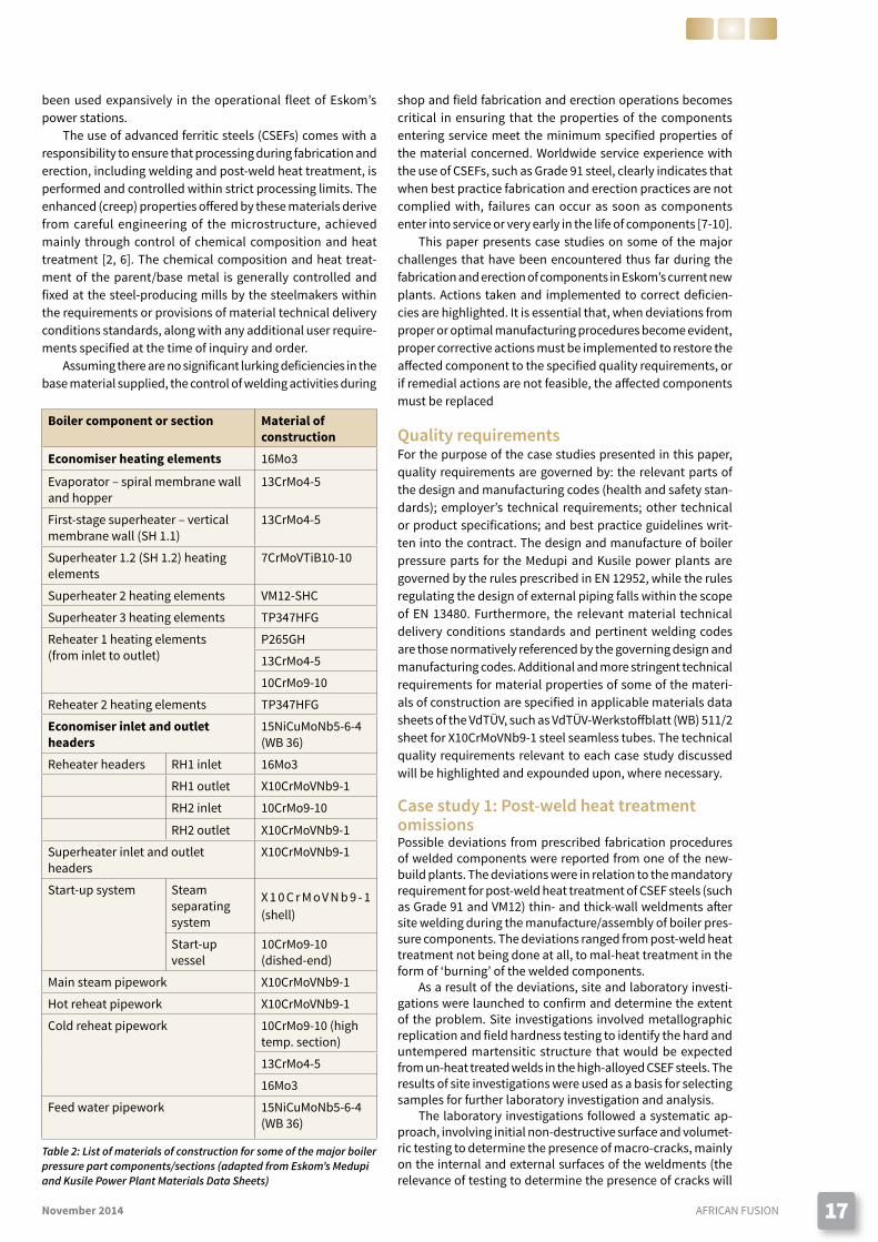
Such steam parameters necessitate the use of creep strength-enhanced ferritic steels (CSEFs), such as Grade 91 steel [2], or X10CrMoVNb9-1 according to Euronorm designa-tions [3]. Advanced high temperature creep-resistant steels are also required for thick-wall boiler components, and on intermediate and final stages of the convective heating sur-faces (thin-wall tubing), in order to cope with the exacting steam-generating conditions within the boiler environment. Table 2 presents the suite of materials used in some of the different sections of the boiler pressure envelop.
As can be seen in Table 2 on page 17, two other advanced ferritic steel grades that form part the family of CSEFs are used in thin-wall superheater tubing, namely, 7CrMoVTiB10-10, commonly known as T24, and VM12-SHC. The austenitic stain-less steel TP 347H FG also finds extensive use in the convective heating surfaces of the last stage superheater and reheater due to its favourable combination of good creep strength and excellent resistance to steam-side oxidation and exfoliation [4, 5]. Lower temperature sections of the heating elements are manufactured from conventional ferritic steels, which have
17November 2014 AFRICAN FUSION
been used expansively in the operational fleet of Eskom’s power stations.
The use of advanced ferritic steels (CSEFs) comes with a responsibility to ensure that processing during fabrication and erection, including welding and post-weld heat treatment, is performed and controlled within strict processing limits. The enhanced (creep) properties offered by these materials derive from careful engineering of the microstructure, achieved mainly through control of chemical composition and heat treatment [2, 6]. The chemical composition and heat treat-ment of the parent/base metal is generally controlled and fixed at the steel-producing mills by the steelmakers within the requirements or provisions of material technical delivery conditions standards, along with any additional user require-ments specified at the time of inquiry and order.
Assuming there are no significant lurking deficiencies in the base material supplied, the control of welding activities during
shop and field fabrication and erection operations becomes critical in ensuring that the properties of the components entering service meet the minimum specified properties of the material concerned. Worldwide service experience with the use of CSEFs, such as Grade 91 steel, clearly indicates that when best practice fabrication and erection practices are not complied with, failures can occur as soon as components enter into service or very early in the life of components [7-10].
This paper presents case studies on some of the major challenges that have been encountered thus far during the fabrication and erection of components in Eskom’s current new plants. Actions taken and implemented to correct deficien-cies are highlighted. It is essential that, when deviations from proper or optimal manufacturing procedures become evident, proper corrective actions must be implemented to restore the affected component to the specified quality requirements, or if remedial actions are not feasible, the affected components must be replaced
Quality requirementsFor the purpose of the case studies presented in this paper, quality requirements are governed by: the relevant parts of the design and manufacturing codes (health and safety stan-dards); employer’s technical requirements; other technical or product specifications; and best practice guidelines writ-ten into the contract. The design and manufacture of boiler pressure parts for the Medupi and Kusile power plants are governed by the rules prescribed in EN 12952, while the rules regulating the design of external piping falls within the scope of EN 13480. Furthermore, the relevant material technical delivery conditions standards and pertinent welding codes are those normatively referenced by the governing design and manufacturing codes. Additional and more stringent technical requirements for material properties of some of the materi-als of construction are specified in applicable materials data sheets of the VdTÜV, such as VdTÜV-Werkstoffblatt (WB) 511/2 sheet for X10CrMoVNb9-1 steel seamless tubes. The technical quality requirements relevant to each case study discussed will be highlighted and expounded upon, where necessary.
Case study 1: Post-weld heat treatment omissionsPossible deviations from prescribed fabrication procedures of welded components were reported from one of the new-build plants. The deviations were in relation to the mandatory requirement for post-weld heat treatment of CSEF steels (such as Grade 91 and VM12) thin- and thick-wall weldments after site welding during the manufacture/assembly of boiler pres-sure components. The deviations ranged from post-weld heat treatment not being done at all, to mal-heat treatment in the form of ‘burning’ of the welded components.
As a result of the deviations, site and laboratory investi-gations were launched to confirm and determine the extent of the problem. Site investigations involved metallographic replication and field hardness testing to identify the hard and untempered martensitic structure that would be expected from un-heat treated welds in the high-alloyed CSEF steels. The results of site investigations were used as a basis for selecting samples for further laboratory investigation and analysis.
The laboratory investigations followed a systematic ap-proach, involving initial non-destructive surface and volumet-ric testing to determine the presence of macro-cracks, mainly on the internal and external surfaces of the weldments (the relevance of testing to determine the presence of cracks will
Table 2: List of materials of construction for some of the major boiler pressure part components/sections (adapted from Eskom’s Medupi and Kusile Power Plant Materials Data Sheets)
Boiler component or section Material of construction
Economiser heating elements 16Mo3
Evaporator – spiral membrane wall and hopper
13CrMo4-5
First-stage superheater – vertical membrane wall (SH 1.1)
13CrMo4-5
Superheater 1.2 (SH 1.2) heating elements
7CrMoVTiB10-10
Superheater 2 heating elements VM12-SHC
Superheater 3 heating elements TP347HFG
Reheater 1 heating elements(from inlet to outlet)
P265GH
13CrMo4-5
10CrMo9-10
Reheater 2 heating elements TP347HFG
Economiser inlet and outlet headers
15NiCuMoNb5-6-4 (WB 36)
Reheater headers RH1 inlet 16Mo3
RH1 outlet X10CrMoVNb9-1
RH2 inlet 10CrMo9-10
RH2 outlet X10CrMoVNb9-1
Superheater inlet and outlet headers
X10CrMoVNb9-1
Start-up system Steam separating system
X 1 0 C r M o V N b 9 - 1 (shell)
Start-up vessel
10CrMo9-10 (dished-end)
Main steam pipework X10CrMoVNb9-1
Hot reheat pipework X10CrMoVNb9-1
Cold reheat pipework 10CrMo9-10 (high temp. section)
13CrMo4-5
16Mo3
Feed water pipework 15NiCuMoNb5-6-4 (WB 36)

AFRICAN FUSION November 201418
an optical microscope to analyse the microstructure (after etch-ing), and to evaluate for the presence of micro-cracks on the internal and external surfaces of the weldments. Lastly, bench-hardness testing was carried out on the prepared cross-weld specimens, following the methodology prescribed in EN 9015.
A selection from the results obtained during laboratory testing is presented in Figures 1 to 5. An average weld metal hardness from site hardness testing is also included with the hardness profiles from the bench laboratory tests for compari-son. The sources and implication of the discrepancies in the site and laboratory hardness testing are briefly addressed later.
The results of laboratory testing confirmed the reported scope of deviations regarding post-weld heat treatment. The hardness testing profiles of Figures 1 and 2 show hardness lev-els indicative of a martensitic microstructure in the as-welded condition – the hardness of untempered martensite in Grade 91 steel is generally in the range 385 HV10 to 410 HV10 for cooling rates of commercial interest [11]. Most of the samples sent for laboratory measurements fell into this category. Figure 3 shows hardness profiles where the outer hardness profile, about 2.0 mm below the external surface, falls below the profiles at the inner and mid-wall locations. Such a profile would be expected from a component where rapid heating to very high temperatures was applied on the outer surface for a short period of time, followed by an abrupt termination of the heating cycle, i.e. with no soak. This phenomenon is referred to as ‘burning’. The hardness measurement results presented in Figure 4, obtained by taking a through-wall thickness hard-ness profile on the weld bead, confirmed the data of Figure 3. The trend, characterised by a drop in hardness, after a slight initial increase, from the inner surface to the outer surface, was confirmed by measurements taken at two opposite locations along the circumference, i.e. at the 12:00 and 6:00 positions. Finally, Figure 5 shows hardness data where the hardness level of all three profiles – outer, inner and mid-wall – is consistent with that expected from a properly tempered martensitic structure in X10CrMoVNb9-1. The hardness level for a properly heat-treated Grade 91 steel weldment is normally in the 200 to 295 HV range [12].
Also evident in the hardness profiles presented in Figures 1 to 3 is the discrepancy in the average hardness levels of the field measurement and average weld metal hardness determined from the outer hardness profile of the laboratory tests. For all samples investigated in the laboratory, hardness measurements were also taken in the same position where field hardness measurements had been taken. This location was used as the 12:00 reference position for laboratory data reporting. On all of the samples tested in the laboratory, the field hardness measurement was always significantly lower (circa 40 to 50 HV lower for tubes with thickness ≥10 mm), and the discrepancy became severe as the wall thickness of the tubes decreased (circa 120 HV lower for a tube with nominal wall thickness of 3.6 mm). These discrepancies highlighted the inadequacy of the technique used at the time when the field hardness testing was conducted for this assessment, and the importance of developing and using sound hardness testing procedures for in-situ hardness testing as part of qual-ity control.
During initial assessments, the Equotip machine, which operates based on the dynamic rebound technique, was employed.
Finally, another salient trend apparent from the hardness testing results was the observation that most of the tubes tested (with the exception of tubes that may have been sub-jected to a ‘burning’ heat treatment) with a thickness ≥ 10 mm exhibited an inner (root) hardness profile with a hardness level substantially lower than the outer (cap) hardness level (Figure 1). This behaviour may be attributed to the tempering of the
Figure 1: Hardness profile from a cross-weld specimen of a 12.5 mm thick butt-welded tube of X10CrMoVNb9-1 steel.
Figure 2: Hardness profile from a cross-weld specimen of a 3.6mm thick butt-welded tube of X10CrMoVNb9-1 steel.
Figure 3: Hardness profile from a cross-weld specimen of a 10mm thick butt-welded tube of X10CrMoVNb9-1 steel, with outer hardness profile falling below the inner and mid-wall profiles.
be addressed later). Magnetic particle testing was used for ex-ternal surface crack detection, while radiographic testing was performed for volumetric detection of macro-cracks across the thickness of the weldments.
The non-destructive examinations were then followed by destructive metallurgical laboratory analysis, following standard metallographic procedures for ferrous alloys. Several cross-weld specimens for laboratory testing were taken from each sample received from site and mounted in Bakelite for ease of handling. The prepared specimens were examined using
Harvey Shacklock Gold Medal Award

November 2014 AFRICAN FUSION 19
inner root weld bead during the deposition of filling passes. Thin-walled components (wall thickness <10 mm) did not display this behaviour. Instead, the three hardness profiles (outer, mid-wall and inner) were overlapping as in Figure 2. A similar trend was evident on 6.3 mm thick tubes.
The micrographs presented in Figure 6 indicate the pitfall and inadequacy of using metallographic replication (or opti-cal microscopy) in isolation when evaluating whether or not a component or weld made from high-alloy CSEF steel has been heat-treated. The micrograph in (a) was taken from a sample with an average weld hardness on the outside of 412 HV10, a hardness level typical of the as-welded condition; while (b) was taken from a weld that was subject to adequate PWHT. Taken on their own, there is not much difference (if any) in the appearance of the two microstructures. Since metallographic replication and hardness testing are commonly used as tools for a quick assessment of the quality of materials such as X10CrMoVNb9-1, it is critical that field hardness testing is per-formed following sound procedures and techniques to provide meaningful hardness data with good accuracy.
Finally, the investigations did not reveal significant inci-dence of cracking on the tubes sent for laboratory testing. Non-destructive testing did not detect the presence of macro-cracks on the outer and inner surfaces of any the samples examined. Only one sample out of 20 tested was found to have a small micro-crack breaking into the inner root surface of a non-heat treated 10 mm thick tube from optical metallographic examinations, as shown in Figure 7. The maximum hardness recorded on the inner root of this tube was 350 HV10.
At the end of the laboratory investigations, it was clear that many welds had not been heat-treated; some welds may have been subjected to ‘burning’, while some had been subjected to adequate PWHT.
The governing design and manufacturing code or health and safety standard, EN 12952-5 clearly indicates that weld-ments on X10CrMoVNb9-1 and other martensitic creep resis-tant steels must undergo a PWHT. Clause 10.4 and associated sub-clauses of EN 12952-5 prescribe requirements for PWHT and it is evident from these that PWHT on materials such as X10CrMoVNb9-1 is mandatory for all wall thicknesses, with no exemptions indicated.
These requirements are necessitated due to the fact that the chemical composition of these materials and matching weld filler has been carefully designed to assure good harden-ability, since a martensitic microstructure is a prerequisite for the enhanced creep properties possessed by martensitic creep resistant steels. Thus, upon cooling in air, the weld and heat-affected zone regions that experienced temperatures above the lower critical transformation temperatures, will transform to virgin martensite characterised by a very high hardness. In the untempered condition, a martensitic microstructure, in addition to being hard and brittle, is susceptible to cracking due to stress-corrosion cracking (SCC) and cold cracking.
Damage due to stress corrosion cracking has been reported on weldments involving X10CrMoVNb9-1 steel as a result of delays in conducting PWHT and consequent exposure of the un-heat treated weldments to moist or damp environments [9]. While the design and construction codes do not specify or indicate whether a time lapse between the conclusion of welding activities and the application of PWHT is acceptable, the best practice is to carry out PWHT immediately after weld-ing, or to preserve un-heat treated weldments of martensitic steels in a moisture-free environment until PWHT is conducted.
It is evident, therefore, that the omission of PWHT on the weldments in this case study inadvertently left them exposed to the risk of damage due to SCC. This was compounded by the fact that it was known that the weldments had come into contact with moisture, due to the fact that a hydrostatic
Figure 4: Through-wall hardness profile on the weld metal of the sample in Figure 3 measured on the 12:00 and 6:00 positions. Plotted with increasing distance from the inner weld bead, with 0 (zero) location 1.0 mm from the inside surface and position 8 at 1.0 mm below the outer surface.
Figure 5: Hardness profile from a cross-weld specimen of a 12.5mm thick butt-welded tube of X10CrMoVNb9-1 steel.
a.
Figure 6: Optical micrographs taken from the final weld pass of samples of X10CrMoVNb9-1 steel with: (a) average outer hardness of 412 HV10 on same sample as that of Figure 3; (b) average outer hardness of 310 HV10. Taken at 500× magnification; etched in Villela’s reagent.
b.
a.
Figure 7: Optical micrographs showing a micro-crack observed on the ID root surface of one of the samples analyzed during laboratory metallographic examinations, taken at: (a) 200×; (b) 1000×. Etched in Villela’s Reagent.
b.

21November 2014 AFRICAN FUSION
pressure test had been performed in some of the affected plant areas prior to the PWHT problems. Additional delays in implementing boiler preservation procedures following hydrostatic pressure testing meant that the un-heat treated welds inadvertently remained in contact with moisture for an extended period of time.
Adopted remedyBased on the observation that tubes with a wall thickness ≥10 mm displayed a reduction in hardness on the inner root – found to be within the range 330 – 350 HV for samples in-vestigated as part of laboratory studies – susceptibility to SCC and thus risk of damage was considered to be relatively low. Overall, the risk of damage due to SCC for weldments that had not received a PWHT was the highest on the inner (root) weld surfaces of the welded tubes since the internal surface had definitely been in contact with moisture. It was thus decided that un-heat treated weldments on tubes with wall thickness ≥10 mm should be subjected to PWHT in accordance with code requirements.
A maximum hardness of 350 HV10 is used as an acceptance criterion during welding procedure qualification according to EN ISO 15614-1, which is normatively referenced by the design and manufacturing code, EN 12952.
As previously mentioned, tubes with wall thickness <10 mm did not show substantial tempering of the inner weld root, and hardness levels as high as 400HV10 were found. Thus the risk of damage due to SCC was considered to be high in such components. Since damage due to SCC can initiate and remain at levels below the detection capabilities of conventional non-destructive testing techniques, it can remain undetected and likely propagate in service even if PWHT is performed. The decision was therefore taken to replace all components with un-heat treated weldments in this wall thickness category.
In order to properly implement the above recommenda-tions, it is apparent that a sound technique and methodology had to be implemented and followed in order to unmistakably identify un-heat treated weldments. As pointed out earlier, the field hardness testing performed as part of the initial as-sessments had unacceptably large underestimation errors compared to the more accurate laboratory hardness measure-ments. To this end, a new procedure using the MIC10 hardness testing machine, based on the ultrasonic-contact impendence (UCI) principle, was adopted and a sound procedure was drawn up to ensure that meaningful field hardness test results could be collected.
Finally, the issue of ‘burning’ of some components was not considered a significant risk in distorting the results of hardness testing. Even though such ‘burning’ heat treatment was shown to result in an outer hardness that is lower than the inside hardness, the hardness level was still found to be much higher than the hardness level typically associated with an adequately heat-treated weldment. For this reason, hardness limits to be used as acceptance criteria for field hardness test-ing were revised to be in line with international best practice. Accordingly a hardness range for X10CrMoVNb9-1 weldments in the range 190 to 300 HV10 [13] was adopted.
Case study 2: WPQRs and Charpy impact joule requirementsDuring reviews of welding procedure specifications (WPS) and associated welding procedure qualification records (WPQR) used in shop fabrication of some pressure-part components,
it became evident that some WPQRs were not performed in the presence of an examiner or examining body. The require-ment for qualifying a welding procedure is clearly articulated in the relevant standard governing the qualification of welding procedures, in this case EN 15614-1. Clause 6.3 of this stan-dard states that ‘welding and testing of test pieces shall be witnessed by an examiner or an examining body’. The design and manufacturing of the affected components is governed by the rules of EN 12952, and Part 6, Clause 6 of this applica-tion standard says that ‘welding procedure specifications shall be qualified for all welds in components forming the pressure circuit or attached to that circuit’, and further states that ‘these qualifications shall be in accordance with EN ISO 15614-1.’ Thus the requirements of EN ISO 15614-1 in relation to welding pro-cedure qualification, are also embedded in the requirements of the application standard.
The main reason for employing an examiner or examining body throughout the process of qualifying a welding proce-dure is to provide for independent assurance and increased confidence in the process through the involvement of an independent party. In view of the non-compliance to the re-quirements of the governing welding procedure qualification, and design and manufacturing standards, a decision was taken to requalify the non-compliant welding procedures so that all requirements of the governing standards would be met. Since the production of components had already started at the time when the decision to requalify the welding procedures was taken, further production and assembly of components on site continued while the welding procedure requalification process took place. The requalification of the welding procedures was mostly successful, and ultimately only four welding procedures failed to meet all prescribed technical requirements. The ma-jor difficulty with the three of the four procedures related to failure to meet the specified Charpy V-notch impact property requirements, while the fourth related to improper/erroneous selection heat treatment conditions.
According to EN ISO 15614-1, Clause 7.4.5, the absorbed impact energy for each notch location shall be in accordance with appropriate parent material standard, unless modified by the application standard. The application standard, EN 12952-2 Clause 4.2.5.4 requires an average Charpy V-notch impact energy of 27 J (transverse) and 35 J (longitudinal) at 20 oC. The relevant parent material standard in this case is EN 10216-2 and it specifies a minimum average absorbed Charpy V-notch impact energy of 27 J in the transverse orien-tation. It is thus evident that the requirements of the design and manufacturing code will be fulfilled when the average absorbed Charpy V-notch impact energy is at least 27 J in the transverse orientation.
In addition to fulfilling the code requirements stated above, additional user requirements for parent material properties were specified through the VdTÜV-Werkstoffblatt (WB) sheets, such as the 511/2 sheet for X10CrMoVNb9-1 steel seamless tubes. This sheet contains more stringent average Charpy V-notch impact energy requirements, specifying a minimum average of 41 J for a transverse notch orientation, and 68 J for longitudinal orientation. This requirement then, being stricter than code requirements, is the one that must be met in order to comply with all relevant technical quality requirements.
The specification of minimum average Charpy V-notch values is a common practice in design and manufacturing codes to minimise the risk catastrophic brittle fracture on fer-ritic steels subjected to operational stresses or test pressures at low temperatures. The commonly used value of 27 J in the applicable design and manufacturing codes was derived from test data generated from low yield strength steels [14,15] us-ing correlations for Charpy V-notch and fracture toughness. In order to assure the same level of defect tolerance for high

strength steels such as X10CrMoVNb9-1, the specification of higher minimum average Charpy V-notch impact energy values is justifiable.
The three impact property-related welding procedures affecting welding joints are summarised in the schematic diagram shown in Figure 8. These were dual-process welding procedures consisting of a tungsten inert-gas (TIG) root and either submerged-arc welding (SAW) or manual metal arc (MMA) filling and capping passes. Welded test pieces used in
procedure qualifications were given a code-minimum PWHT cycle in a furnace. A brief description of the welding parameters and consumables for the affected procedures follows below.
Welding procedure 141/121: P91 to P91 This procedure employed dual process welding involving a root layer and three hot runs deposited using the manual tungsten-inert gas (TIG) welding process, followed by filling and capping using the submerged arc welding process. The weld joint was a full penetration butt weld performed on a U-groove on 85 mm thick by 395 mm OD test piece of X10CrMoVNb9-1. Welding was performed with a minimum preheat temperature of 200 oC and maximum interpass temperature of 300 oC. Additional weld-ing process-related information is provided in Table 3 below.
Table 4 presents a summary of tensile and impact test results for the 141/121 P91 to P91 welding procedure based on tests conducted on welded test pieces and from samples prepared from actual production components. The test results for the original non-compliant procedure had impact energy values that exceeded all requirements.
However, notwithstanding the non-compliance with regards to the absence of an examiner or examining body, the recorded impact energy values were taken after two heat treatment cycles. One heat treatment cycle is defined as the
total soak duration calculated from a normalised soaking time prescribed in EN 12952-5, Table 10.4-3 for determin-ing minimum code allowable soaking time; specifically; 2.5 min/mm for X10CrMoVNb9-1.
It is standard practice to qualify the welding procedures with multiple heat treatment cycles in order to accom-modate additional heat treatments that may be required should a repair during fabrication become necessary. The erroneous custom of performing mechanical tests after at least two heat treatment cycles was often repeated, and this presented confounding chal-lenges in the interpretation of the results, particularly due to the fact that the execution of post-weld heat treat-ment on production components was performed in single cycles.
For this reason, a decision was made to select and subject production compo-nents to destructive mechanical testing in accordance with testing philosophy prescribed in the governing welding procedure qualification standard, EN 15614-1. Some of the results obtained from production component tests are also presented in Table 4.
It is evident from these results that the impact values obtained from the production components were abysmal, substantially lower than the minimum requirements of the health and safety standard that have already been ex-pounded in the foregoing discussion. The low impact values were evident on
Figure 8: Schematic representation of the weld joints for the welding procedures affected by impact energy-related non-conformances.
P91
P91
P91
10Cr
P91 matching filler
P91 matching filler
Procedure Comments PWHTtemperature
(oC)
Weld metal impact values Tensilestrength
141/121‘P91 toP91,TIG/SAW
1 2 3 Average 1 2
Original1 750 98 100 92 97 642 663
1st re-qual.2 760 152 158 139 150 630 666
2nd re-qual 3 760* 59 36 57 51 542 604
3rd re-qual 760 24 32 31 29 633 656
4th re-qual 760 60 62 38 53 - -
inter test4: top 765 33 51 25 36 660 678
bottom 32 22 28 27
Inter test5: top 765 68 134 87 96 649 674
bottom 40 77 25 47
Prod test6: top 750 20 8 17 15 662 683
bottom 11 29 14 18
Prod test7: top 750 12 10 11 11 - -
bottom 12 9 12 11
Tungsten-inert gas (TIG) Submerged-arc (SAW)Filler wire W CrMo91 S CrMo91
Shielding and backing gas 99.99% argon -
Flux - SA FB 2 55 DC H5
Process thickness (mm) 8.0 77
Heat input (kJ/mm) 0.87 to 2.03 0.93 to 1.56
Table 3: Welding process details for procedure 141/121: P91 to P91
Table 4: Summary of mechanical testing results obtained from welding test pieces and destructive mechanical testing on selected production components for welding procedure 141/121 P91 to P91.
Notes: 1: Original procedure with no examiner or examining body. 2: Interpass temperature changed from original procedure used in production. 3: Temperature excursion experienced during PWHT at 780 oC for 30 mins, while the code-allowable temperature range is 740 to 770 oC. 4: Internal testing not done as part of procedure qualification. 5: Re-test of 4. 6: Tests from randomly selected production weldments. 7: Re-test from additional material of 6.
Harvey Shacklock Gold Medal Award
AFRICAN FUSION November 201422

November 2014 AFRICAN FUSION 2323
Charpy V-notch specimens prepared from the top (beneath the outer surface) and bottom (in the vicinity of the root) positions, with the notch located in the weld metal.
Analysis of the impact energy values measured after ex-tended soak times (two or more cycles) from welded test pieces produced for procedure qualification tests revealed a trend that showed an improvement in the impact energy values with increased soak time. This trend pointed to a framework for the qualification of a welding procedure that fulfils the specified requirements for minimum average impact energy values, and for the rehabilitation of non-conforming products.
Production welding using this welding procedure covered a limited number of components. Due to the very low impact energy values reached by components produced to this weld-ing procedure, along with reported inconsistencies on tensile test results, it was decided to replace all welds on production components made from this welding procedure. Since some of the affected components had already been assembled and installed on site, the rework involving these welds was carried out in-situ. A new and fully compliant welding procedure was successfully qualified by increasing the minimum post-weld heat treatment soaking time, which was then systematically implemented during the production of re-placement welds and for further shop fabrication.
Welding procedure 141/111: P91 to P91 For this procedure, once again dual process welding was applied, with TIG used to de-posit the root run and a hot run followed by filling and capping using manual metal arc welding (MMA). A butt-welded (U-groove) test piece 50 mm thick by 270 and 360 mm ID was produced from X10CrMoVNb9-1 steel and subjected to testing in accordance with the requirements of EN ISO 15614-1. Welding was performed with a minimum preheat temperature of 200 oC and maxi-mum interpass temperature of 250 oC. Table 5 below furnishes additional welding process-related details.
A summary of Charpy V-notch impact and tensile test results determined from test pieces made during the qualification of this welding procedure is presented in Table 6. Once again due to the fact that mechanical testing during procedure qualification was often performed after at least two post-weld heat treatment cycles, while production components would only receive one heat treatment cycle, additional mechanical tests were carried out on welds taken from samples of actual production components. Samples were taken from two different production components (1 and 2) and subjected to the same scope of mechanical testing prescribed in EN ISO 15614-1. The sampling criterion for pro-duction component one required a sample to be taken from a component with the largest wall thickness welded according to this procedure and subjected to post-weld
heat treatment at the lowest temperature (or range). Produc-tion component two was selected based on the largest wall thickness that was subjected to the highest post-weld heat treatment temperature (or range). The largest wall thickness for the lower and upper bound of PWHT temperatures applied during production of components to this welding procedure was selected as it represented the most optimistic conditions (longest soaking time). The test results obtained from the production components are also presented in Table 6.
From an analysis of the results obtained from samples of the two production components, a wide scatter in the results of impact energy values obtained from welds performed us-ing this procedure is evident. Notwithstanding this scatter, it is also apparent from these results that even under the most optimistic conditions encountered in production, one of the production components (component two) failed to meet the minimum requirements of the governing health and safety standard (minimum average impact value of 27 J). While the other component (component one) met the minimum require-ments of the health and safety standard, it failed to fulfil the additional specified user requirements of a minimum average impact value of 41 J.
Tungsten-inert gas (TIG) Submerged-arc (SAW)Filler wire W CrMo91 E CrMo91 B 4 2 H5
Shielding and backing gas 99.99% argon -
Process thickness (mm) 6 to 8 42 to 44
Heat input (kJ/mm) 0.88 to 1.98 (root run)1.38 to 3.85 (hot run)
0.99 to 1.65
Procedure Comments PWHTtemp. (oC)
Weld metal or HAZ# impact values (lowest)
Tensile strength
141/111‘P91 toP91’TIG/MMA
1 2 3 Average 1 2
Original1: top 750 59 74 70 68 714 723
Original: bottom
61 55 55 57
Re-qual2: top 750 41# 40# 38# 43# 681 675
bottom 40# 62# 118# 73#
Prod comp 1 3) 740 - 750 36 56 29 39 678 690
Prod comp 14 750 86 103 47 79 682 -
Prod comp 25 750 - 765 15 15 22 17 702 701
Prod comp 26 750 88 48 52 63 694 694
Table 5: Welding process details for procedure: 141/111, P91 to P91.
Table 6: Summary of mechanical testing results obtained from welding test pieces and destructive mechanical testing on selected production components for welding procedure 141/111, P91 to P91.
Notes: 1: Original procedure with no examiner or examining body; mechanical testing performed after 3 PWHT cycles (125 min×3). 2: Failed bend test; mechanical testing performed after 2 PWHT cycles (125 min×2); lowest Charpy impact values reported to be in the HAZ. 3: Tests from a sample of a production component 1 (42.5 mm thick by 210 mm ID) welded to this welding procedure with PWHT (single cycle of 110 min) performed at the lowest temperature within the allowable temperature range and the highest wall thickness. Charpy V-notch and tensile test specimen taken in the area of the root. 4: Tests from a sample of remaining material from Production Component One after a second PWHT cycle of 110 min (cumulative soak time of 220 min). Charpy V-notch and tensile test specimen taken in the area of the root. 5: Tests from a sample of a Production Component Two (39 mm thick by 275 mm ID) welded to this welding procedure with PWHT (single cycle of 103 min) performed at the highest temperature within the allowable temperature range and the highest wall thickness. Charpy V-notch and tensile test specimen taken in the area of the root. 6: Tests from a sample of remaining material from Production Component Two after a second PWHT cycle of 103 min (cumulative soak time of 206 min). Charpy V-notch and tensile test specimens taken in the area of the root.

Unlike the previous procedure discussed earlier, the scope of components welded to this procedure was extensive and thus replacement of the affected components was not a feasible option. A solution that involves a rehabilitation of components affected by this procedure was thus explored and developed. To this end, remnants of samples taken from the two production components were subjected to an additional PWHT cycle using the same heat treatment parameters of the first PWHT cycle. Following the second PWHT cycle, me-chanical testing was again conducted in accordance with the requirements of EN ISO 15614-1. The results, also included in Table 6, confirmed that the second PWHT cycle improved the impact properties of the welds to the extent that all technical requirements related to impact energy and tensile strength were fulfilled.
These results formed the basis of an extended scope that was developed and implemented to rehabilitate all compo-nents fabricated to this procedure, involving the execution of
an additional post-weld heat treatment cycle on components that had only been subjected to a cumulative soaking time equivalent to a single PWHT cycle during shop production. Comprehensive non-destructive testing requirements, entail-ing surface and volumetric examination, along with metallo-graphic replication on all affected welds, were also prescribed as part of the extended scope before and after the additional PWHT in order to ensure component integrity complied with all technical quality requirements after completion of all manufacturing operations.
It must be noted that hardness testing as required by EN ISO 15614-1 was also performed along with the other tests. Hardness testing results were always within the ranges speci-fied in the technical quality requirements.
Welding procedure 141/121: P91 to 10CrThe final procedure affected by non-conformances to the impact energy requirements involved a combination of
X10CrMoVNb9-1 and 10CrMo9-10. This welding procedure also involved dual processes with TIG used to deposit the root and up to three hot runs, followed by filling and capping with submerged arc welding. For the original procedure, a full penetration U-groove butt-welded test piece, 40 mm thick by 335 mm OD was used. During requalification the di-mensions of the welded test piece changed slightly to 36 mm by 322 mm OD. A minimum preheat temperature of 250 oC was applied, with a maximum interpass temperature of 300 oC reached during welding. Addi-tional welding process related details are recorded in Table 7 opposite.
Table 8 presents a summary of the test results obtained from Charpy V-notch and tensile testing. Again, failure to sys-tematically execute mechanical testing after each PWHT cycle during procedure qualification made the task of interpreting the results difficult. However, since the trend of impact prop-erties for production compo-nents had already been es-tablished based on work done for the two aforementioned procedures, additional work on this procedure focused on validating a procedure for re-habilitating the impact proper-ties of production components welded to this procedure, based on executing an additional PWHT cycle, in line with the
Harvey Shacklock Gold Medal Award
AFRICAN FUSION November 201424

November 2014 AFRICAN FUSION
References1. M Koko, R Duff: Modern Power Systems: October 2009. pp 20-25.2. The Grade 91 Steel Handbook: EPRI, Palo Alto, CA: 2013.
3002001465.3. The T91/P91 book: V&M Tubes, 2000 edition.4. A Iseda, H Okada, H Semba and M Igarashi: Energy Materials:
2007, Vol. 2, No. 4, 199-206.5. J Jianmin, M Montgomery, OH Larsen and SA Jensen: Materials
and Corrosion, 2005, 56, No. 7, 459 – 467.6. J Henry, K Bezzant and W Wiess: Inspection Issues with CSEF
Steels, in ‘Proceedings of Welding and Repair Technology for Power Plants: 10th International EPRI Conference, June 25-28, 2012: Marco Island, FL USA.’
7. J Parker: International Journal of Pressure Vessels and Piping, 101 (2013), 30-36.
8. S Brett: Energy Materials, 2007, Vol. 2, No. 2, 117-121.9. Service Experience with Grade 91 Components: EPRI, Palo Alto,
CA: 2009. 1018151.10. J Parker: International Journal of Pressure Vessels and Piping,
114-115 (2014), 76-87.11. A Fleming, RV Maskell, LW Buchanan and T Wilson: Materials De-
velopment for Supercritical Boilers and Pipework, in Materials for High Temperature Power Generation and Processing Plant Applications: edited by A Strang, Institute of Materials, 2000.
12. DJ Abson and JS Rothwell: International Materials Reviews, 2013, Vol. 58, No. 8, 437-473.
13. VGB-R 109 Directive: Materials Specification for Components under Pressure in Fossil-Fired Power Plants, Second Edition (2008). Published by VGB PowerTech e.V.
14. R Sandström, P Langenberg, H Sieurin: International Journal of Pressure Vessels and Piping, 82 (2005), 872-881.
15. CS Wiesner, SJ Garwood, R Sandstrom, DM Street, KJ Coulson: International Journal of Pressure Vessels and Piping 78 (2001), 391-399.
2525
methodology adopted for 141/111 ‘P91 to P91’ procedure.
Validation of the effectiveness of an additional PWHT cycle in restoring impact properties was also critical for this procedure, due to the combination of high strength and low strength materials. While it had been established at this stage that an additional PWHT cycle would improve the impact prop-erties, there was always the risk that another cycle would lead to degradation of the tensile properties of the weaker parent metal to val-ues lower than those specified for the base metal in the technical delivery conditions’ standards.
For the purpose of this validation an additional test piece was welded using the welding parameters of this procedure. The test piece dimensions were 40 mm thick by 243 mm ID on the 10CrMo9-10 side and 55 mm thick by 225 mm ID on the X10CrMoVNb9-1 side. Mechanical testing was first conducted after a single PWHT cycle. The remnant ma-terial was then subjected to a second PWHT cycle and subjected to mechanical testing again. The results of this endeavour are pre-sented in Table 8.
From analysis of the results of the ad-ditional test piece, it was again apparent that a single PWHT cycle falls short of the additional user requirements on minimum average impact values, even though the requirements of the health and safety standard were fulfilled. An additional PWHT cycle improved the impact properties and fulfilled specified technical quality requirements, as expected.
As was also anticipated, however, degradation of the me-chanical properties of the weaker parent metal left the tensile strength after the additional PWHY cycle hovering very close to the minimum tensile strength (480 MPa) stipulated in the relevant technical delivery standard, EN 10216-2. Production components welded to this procedure during manufactur-ing were thus added to the extended scope for additional PWHT, with due consideration to the risk of tensile property degradation.
ConclusionsThe case studies presented in this paper have explored some of the challenges that have been experienced thus far dur-ing fabrication and installation of components on Eskom’s current new build power plants. The root-causes for these challenges are multifarious, ranging from mistakes that led to omission and application of inappropriate post-weld heat treatment practices, to a lack of systematic qualification of welding procedures with due consideration to all requirements of the governing standards and stipulated technical quality requirements.
Standard laboratory techniques were successfully utilised to develop practical and cost-effective engineering solu-tions. The efficacy of the adopted solutions in rehabilitat-ing non-conforming products was demonstrated based on laboratory tests conducted on samples of actual production components.
Tungsten-inert gas (TIG) Submerged-arc (SAW)Filler wire W CrMo91 S CrMo91
Shielding and backing gas 99.99% argon -
Flux - SA FB 2 55 DC H5
Process thickness (mm) 6 36 (or 30)
Heat input (kJ/mm) 1.05 to 1.87 1.37 to 1.79
Procedure Comments PWHTtemp. (oC)
Weld metal impact values Tensile strength
141/121, P91 to10CrTIG/SAW
1 2 3 Average 1 2Original1: top 750 24 29 29 27 555 535
bottom 70 41 61 57
Re-qual2 top 760 147 139 138 141 524 497
bottom 158 172 155 162
3rd test piece3 750 21 37 57 38 498 -
3rd test piece4 745 47 52 34 44 483 -
Table 7: Welding process details for procedure: 141/121, P91 to 10Cr.
Table 8: Summary of mechanical testing results obtained from welding test pieces for welding procedure 141/121: P91 to 10Cr.
Notes: Original procedure with no examiner or examining body; mechanical testing performed after a total soak time of 4 hrs 30 mins. 2: Interpass and PWHT soak temperatures different from those of original procedure; mechanical testing performed after two cycles of PWHT. 3: Re-welded test piece (40 mm thick by 243.9 mm ID of 10Cr to 55 mm by 225 mm ID X10) with mechanical testing performed after a single PWHT cycle (114 min). Charpy V-notch and tensile test specimens taken in the area of the root. 4: Testing on the remnant material of the third test piece after additional PWHT cycle; temperature slightly reduced, and cycle time slightly increased to 126 min. Charpy V-notch and tensile test specimens taken in the area of the root.

AFRICAN FUSION November 20142626
Energy sector welding
Worldwide, there is increasing demand for steel and welding consumables in the energy sector, specifi-cally for power plant applications and for the storage
of liquefied gases. The power plant industry, because of escalat-ing demand for electric power, has been growing dramatically, as has the demand for in order to reduce dependence on oil. Liquid natural gas (LNG) exploits the gaseous by-product of oil exploration and is a less polluting fuel with lower CO2 and sul-phur emissions, it contributes to a cleaner global environment. The welding and consumable requirements for storage vessels for liquefied gases will be dealt with in Part 2 of this paper.
Power plant applicationsPower plant applications involve high pressure and high temperature, where the main focus is on high structural in-tegrity for service at elevated temperature as well as longer life cycles, using materials with higher creep strength. The major challenge facing the power generation industry in the 21st century is to achieve the targets for increased efficiencies demanded by both mature economies and developing nations. Environmental regulations requiring reduced CO2 emissions coupled with inevitable pressures on reliability, availability and maintainability will all be major driving forces. Materials devel-opments, and in particular advanced creep resisting steels for high temperature pressure components, will continue to play a significant role in improvements for existing plants and will increasingly do so in new projects. Modified 9%CrMo steels (P/T91) are already well established and variants such as P92 and E911 are taking their share of the market. The advantages of such steels are reduced design wall thickness for a given set of service conditions, with consequent improvements in thermal efficiency. Of course, such advantages can only be fully exploited provided these steels can be welded with ap-propriate welding consumables to give weldments which will not compromise the integrity and operating lifetime of the completed structure.
‘Super 9 chrome’ alloys were initially evaluated for power boiler use in the late 1950s, however the present generation of P91 steels, 9%Cr-1%Mo with controlled additions of Nb, V
and N arose from a USA development programme. The com-monly used descriptors are: T91 for Alloy 91 Tube; P91 for Alloy 91 Pipe; F91 for Alloy 91 Forgings, but for simplicity in the remainder of this paper the material will be referred to as P91, meaning modified 9%Cr-1%Mo, not specifically pipe.
Welding consumables, to a variety of specifications, have been in continuous production and use and, in the last 20 years, many hundreds of tons of P91 consumables have been supplied for both repair and upgrading of existing power sta-tions and for the construction of new. Research work continues to introduce new products, to generate data and to increase our understanding of the welding of P91. See Table 1.
Modern combined cycle units (CCUs) that aim to produce electricity at very high thermal efficiencies are increasingly using P91 for the high temperature and superheated steam lines. The basic principle of CCUs is that natural gas fired gas turbines generate power in their own right, but the high temperature exhaust gases are used to produce steam in a recuperation boiler, which then powers a steam turbine for additional electricity generation. Depending on design, the units may be single- or multiple-shaft types, where single-shaft types have a common shaft for both steam and gas turbines.
Weld metal compositionsThe P91 parent material composition is essentially 0.1% C; 9% Cr; and 1% Mo, modified with controlled additions of V, Nb and N to give long term, high temperature creep strength. The composition is balanced with the aim of producing a fully martensitic microstructure with little or no retained delta fer-rite. The weld deposit composition is designed to be as close as possible to the parent P91 steel, consistent with achieving optimum properties, weldability and microstructure. Early work on matching compositions showed that the toughness of the weld metal was rather low, particularly when treated with shorter and lower temperature post weld heat treatment (PWHT) cycles, e.g. two to three hours at 750-760 °C.
In order to achieve the optimum balance of creep proper-ties and toughness, the weld metal compositions needs to differ from the parent alloy as follows:
Part 1 of this paper deals with welding consumables for the modern power sector, in particular the modified 9%CrMo steels (P/T91) and their variants, such as P92 and E911. Part 2, which will be published in the next issue of African Fusion, deals with the welding and consumable requirements for storage vessels for liquefied gases at cryogenic temperatures.
Welding consumables and proceduresfor the energy sector: Part 1:V. van der Mee, Lincoln Electric Europe
C Mn Si Cr Ni Mo Nb V N min 0.08 0.30 0.20 8.00 - 0.85 0.06 0.18 0.03
max 0.12 0.60 0.50 9.50 0.40 1.05 0.10 0.25 0.07
Table 1: Specified P91 steel composition

November 2014 AFRICAN FUSION 2727
• Reducing Niobium content below that of the parent steel (0.06-0.10%) improves weld metal toughness. In order not to compromise creep resistance, 0.04% to 0.07% is considered optimum.
• Nickel is beneficial in improving toughness for two rea-sons: it lowers the Ac1 temperature, which improves the response to tempering, and it reduces the tendency for formation of undesirable δ-ferrite. Excessive nickel (>1%) is detrimental as it can reduce the Ac1 below the PWHT temperature and result in the formation of fresh untem-pered martensite. Nickel is usually controlled in the range 0.4–1.0%, although some authorities require <0.4%, as in the parent material.
• Manganese is generally controlled at a higher level than the parent material to promote de-oxidation and to en-sure a sound weld deposit. However, some authorities limit Mn+Ni to 1.5%, or even to a 1.0% maximum, to avoid austenite reformation at the highest PWHT temperatures.
• Silicon is an essential de-oxidant and in conjunction with chromium it contributes, in a small way, to the al-loy’s oxidation resistance. A low level of Si benefits weld toughness.
• Vanadium, carbon, nitrogen all have a minor influence on toughness, unless incorrect balance leads to ferrite formation. Weld metal ranges and values are essentially the same as the parent alloy to maintain good creep performance.
Consumable specificationsThe European and USA weld metal specifications are similar to the parent material specifications. The Mn and Si levels, partic-ularly in the European EN specifications have been broadened to accommodate a number of different manufacturers’ design philosophies. The Ni limit recognizes the beneficial effects on toughness with a maximum up to 1.0% in most specifications and minimum of 0.4% in the EN specifications.
The minimum levels for the Nb, V and in some cases N strengthening elements are lowered compared to the parent material specification, this recognises the beneficial effects on toughness. The mechanical property requirements of the weld metals are generally in line with the parent steel except that slightly lower minimum elongations are permitted and minimum toughness values are mandatory in the EN specifica-tions, whereas values are by agreement in AWS.
There is some divergence in specified preheat and inter-pass temperatures for test plates to determine mechanical properties. The lower range of 205 ± 55 °C in AWS A5.28 for filler wire, compared with 260 ± 28 °C in AWS A5.5 for covered elec-trodes, can be justified with respect to the process-dependent levels of potential hydrogen. However, this logic has been re-versed in the EN specifications for no apparent reason; 250 °C ± 50 °C in EN 1599 for covered electrodes and 300 °C ± 50° in EN 12070 for solid wires. Fabrication welds typically employ a preheat/interpass range of 200 to 300 °C. PWHT requirements vary with respect to time at temperature; the AWS requirement is one hour and the EN requirement is three hours for solid wires and two to three hours for covered electrodes. In practice, the one-hour PWHT applied in AWS is too short, where times used in the EN standards are more representative.
Welding processesThe choice of welding process depends on a number of factors, such as size and thickness of the component to be welded, shop fabrication or site repair, availability of suitable equip-ment, necessary skilled staff, availability of suitable consum-ables, and the mechanical properties required, particularly toughness. Table 2 shows the arc welding process options for high temperature power plants.
Welding P91 to dissimilar materialsThe use of P91 is applied where its combination of properties are most appropriate, so it is inevitable that joints between dissimilar creep-resisting steels are often necessary. These usually involve lower alloy ferritic types such as P22 (2CrMo) or one of the lean CrMoV alloys. Occasionally joints may be needed between P91 and one of the austenitic stainless heat resisting steels such as 316H. The joining of P91 to ferritic and austenitic alloys requires some consideration.
P91 to P22 or other low alloy steelsAlthough P91 has been used over a significant period of time for welds between dissimilar materials, there is no universally accepted recommendation for a particular weld metal compo-sition or procedure. Relevant guidance for welding dissimilar creep resisting steels includes:• Matching the lower alloy, 2CrMo.• Matching the higher alloy, P91.• Using an intermediate composition (5CrMo or 9CrMo).
Component Joint type Possible arc welding process Boiler panel Site welding, Repair Manual TIG, and SMAW Manual/orbital
TIG, and SMAW
Superheater, reheater, economizer Tube to tube spacers, Attachments Site welding
Fixed/orbital TIG, Manual TIG, and SMAW
Manual TIG, and SMAW Manual/orbital TIG, and SMAW
Steam pipe work, headers Butt welds, Stub to header, Butt welds, Site welding
TIG, SMAW, FCAW, and SAW Manual TIG, and SMAW Mechanical MIG and TIG Manual TIG, SMAW, orbital TIG, FCAW
Pressure vessels Butt welds TIG, SMAW, FCAW, and SAW
Valve chests Butt welds Mainly TIG, SMAW, FCAW and SAW
Loop pipe work Butt welds Site welding Mainly TIG, SMAW, FCAW and SAW TIG, SMAW and FCAW
Table 2: Welding process options for power plants.

November 2014 AFRICAN FUSION 2929
• Using a different alloy to any of these, in practice a nickel base alloy.
Preference is given to the lower alloy option, on the grounds that it should be sufficient to match the weaker of the two materials being joined. A nickel base weld metal might be considered where stainless steel or nickel alloy base materials are involved. It is also important to consider the most appropri-ate PWHT regime to reconcile the different optimum ranges: for P91, 730 to 790 °C; and for P22, usually 680 to 720 °C; and the weld metal.
PWHT temperature is a compromise and in general is ap-plied at the lowest temperature for the higher alloy material, so a temperature of around 720 to 730 °C, for one to three hours, is typical. This is sufficient to temper the P91 HAZ without over-tempering the P22, and is also a satisfactory temperature for welds using either 2CrMo or 9CrMo consumables. The use of 2CrMo is consistent with procedures used by some fabricators who firstly butter the P91 with 2CrMo and PWHT at ~760 °C. The joint is then made between the P22 and buttered P91 using 2CrMo consumables followed by a 720 °C PWHT. This procedure avoids the need for field joints between dissimilar materials by allowing a joint between P22 and 2CrMo buttering to be carried out on site.
P91 to austenitic or higher alloysBased on many years of experience with dissimilar welds between ferritic and austenitic stainless steels, nickel base consumables are used because they provide the required metallurgical compatibility, long-term creep strength and ductility. In joints with austenitic stainless steels, the effect of PWHT on the stainless steel should be considered. The use of 309 consumables with moderate ferrite content is accepted for welding ferritic/martensitic steels to austenitic stainless steels where the joint service temperature is below 315 °C. Above this temperature, excessive carbon migration, micro-structural instability and the high expansion coefficient
relative to the low alloy material leads to unsatisfactory performance.
New developmentsThe commercial application of P91 is now well established but the development of this alloy system has continued with further improvements in performance. In the new modified steels, creep strength is increased by adding W to raise the Mo-equivalent (Mo + 0.5W) from 1% to about 1.5% in a matrix essentially similar to P91. Two new steels, P92 and P911, are now commercially available (P92, with 0.5%Mo, 1.8%W and P911 with 1%Mo-1%W). Welding procedures for these materi-als are essentially similar to those applied to P91.
Further active developments are aimed at increasing the applicable service temperature of W modified steels by raising Cr to around 11% to improve hot corrosion resistance. There are also a number of developments based on the P22 alloy system e.g. P/T23 and P/T24. These base materials show creep properties approaching those of P91. As with the application of P91, the driving force for these developments is not only the advantage of higher strength to allow thinner sections with improved heat transfer and thermal fatigue performance, but also the environmental imperative, which requires new and improved materials for advanced power plants operating at higher temperatures with the maximum thermal efficiency.
Conclusion Power plant applications, involving high pressure and high temperature, focus mainly on high structural integrity for service at elevated temperature as well as increased lifecycles, using materials with higher creep strength. Base materials involved include traditional CrMo steels as well as enhanced grades like P23, P24, P911 and P92.
A description is given for these steel grades as well as the filler materials and welding procedures required to achieve acceptable quality joints.

AFRICAN FUSION November 20143030
Pipe welding solutions
Particularly well suited to power generation and petrochemical applications, Miller’s PipeWorx
solution comprises two ‘siblings’, the PipeWorx 400 for fabrication shops and the FieldPro 350 for site work. Both are multi-process, inverter-based welding power sources, purpose built for ad-vanced and convenient pipe welding. “The PipeWorx FieldPro 350 solution is particularly suited to site work, because it does not need a separate control ca-ble. It sends all communication signals through the welding cables, making the system as robust as a basic stick welder,” begins Pieterse.
Afrox is conducting welding proce-dure qualification tests using the Pipe-Worx 400 on applications for the power and petrochemical sectors. “We have already developed a welding procedure specification for 210 mm OD carbon steel pipe and we are now moving on to qualifying procedures for more exotic steels used in the industry. When we get these procedures qualified, it will be a quality, productivity and skills game changer for the South African welding industry,” he suggests.
Pipe welding with high quality requirements is conventionally done using tungsten inert gas (TIG) welding
for the weld root and the hot pass. The joint is then usually filled using stick welding (manual metal arc, MMA). “Both of these processes require high levels of skill to achieve quality, flaw-free welds,” Pieterse continues. “This new process, we believe, can remove the requirement for high level skills for pipe welding while improving quality and productivity. It al-lows TIG-quality welding to be achieved using the advantages of the gas metal arc welding (GMAW) process,” he adds.
RMD for pipe root weldingDescribing how the system works, Seleka says that PipeWorx offers two advanced GMAW arc welding control options: Regulated Metal Deposition (RMD), an electronically controlled dip-transfer mode output solution for the root-pass welds; and ProPulse, an open arc pulsed solution for fill and capping passes.
“RMD welding is an advanced short circuit GMAW process that produces precisely controlled metal transfer, mak-ing it easier for the welder to control the power and the weld pool,” says Seleka. Describing the traditional short-circuit cycle, he says the process involves the molten tip of the wire short circuiting in the weld pool up to 200 times per second. “Four distinct phases can be identified in the short circuit welding cycle,” he explains.
During Phase 1, the molten metal at the end of the wire touches the weld pool, causing a short circuit. In Phase 2, resistance heating and the associated magnetic field surrounding the wire from the rising short-circuit current
At Electra Mining Africa, 2014, Afrox featured PipeWorx, an advanced multi-process pipe welding solution from Miller Electric. African Fusion talks to Johan Pieterse, Afrox business manager for manufacturing, and Tshidiso Seleka, the company’s advanced applications development manager.
Raising the pipe-weldingproductivity bar
Afrox’s Tshidiso Seleka, advanced applications development manager and Johan Pieterse, business manager for manufacturing.
Miller’s FieldPro 350 for site work and PipeWorx 400 for fabrication shops. When welding procedures are qualified, the PipeWorx welding system “will be a quality, productivity and skills game changer for the South African welding industry,” according to Pieterse.

November 2014 AFRICAN FUSION 3131
causes the molten metal droplet to neck down or pinch at the solid/liquid interface. In Phase 3, the molten droplet detaches and is deposited into the weld puddle, breaking the short circuit and causing the arc to reignite, often explosively. In Phase 4, while the arc is melting the tip of the wire, the wire be-gins to approach the base metal again. The cycle then repeats, returning to Phase 1 when the droplet touches the weld pool.
“In traditional short circuit process, short circuiting is er-ratic with varying intensity, leading to different sized droplets and inconsistently high arc re-ignition currents, which cause spatter,” says Seleka. From the welder’s perceptive, this pro-duces an agitated weld puddle that is not easy to manipulate. Molten metal from the turbulent puddle can wash up the sides of a joint, causing lack of fusion or cold lapping.
The RMD current waveform anticipates and controls the short circuit current phase of the process to improve the consistency of the metal transfer and short circuit stability. As well as reducing spatter, the net effect is a weld pool with less turbulence. This allow the welder to control the position of the weld pool, avoid lapping and washing of molten metal up the side walls, enabling him or her to produce consistent quality welds in terms of both fusion and weld bead profile.
Describing production advantages, Seleka says that a highly skilled stick welder can achieve an acceptable quality root weld at speeds between 75 and 125 mm/min in the verti-cal up positions and between 125 to 200 mm/min if welding vertically down. “But starts and stops are needed to replace electrodes and slag deposits must to be cleaned off, which further affects cycle times,” he says.
TIG welding gives a higher quality weld root, but at slower speeds of between 50 and 125 mm/min, and more highly skilled welders are required. For pipe welding, TIG welders will also have to reposition themselves around the joint several times to achieve the necessary manipulation control.
“RMD allows a moderately skilled welder to achieve high quality root welds at 150 to 250 mm/min using a solid wire and, on pipes over 500 mm in diameter, speeds of up to 300 mm/min are being achieved,” says Seleka. In addition, because the wire is continuously fed, fewer starts and stops are needed. “Also, because of the higher deposition rate of the process, RMD produces a throat depth of between 3.0 and 5.0 mm, which will usually eliminate the need for a hot pass, typically applied when using the TIG process,” he says.
Pieterse adds: “It also offers excellent tolerance for mis-alignment and gaps up to 5.0 mm can be bridged. But the biggest advantage is in training. An ordinary welder can master the RMD process in less than two days, while an experienced MIG welder needs only two to three hours to become fully proficient.”
ProPulse for capping runsWhile RMD has been optimised for root welding, the PipeWorx system relies on a pulsed-GMAW process for faster fill and cap-ping passes. “There is a huge set-up advantage in being able to use the same welding equipment and process for the root, fill and capping passes,” continues Seleka. “All that has to be done after the root has been completed is to switch modes on the power source and choose the program settings for the capping procedure,” he says.
ProPulse offers high speed and deposition rates and its focused arc cone, short arc lengths and low heat input result in a fast freezing puddle and good weld-pool controllability. Nar-
A capped surface profile completed using the ProPulse feature with its hybrid CV/CC characteristic.
Afrox welding specialist, Houston Isaacs, demonstrates the RMD and ProPulse capabilities of the PipePro 400.
row joints can be accommodated and both vertical up and vertical down welding is possible. “Critical for the welder is the easier puddle control as-sociated with the process compared to traditional pulse or spray GMAW,” says Seleka.
Describing the current regulation of the ProPulse waveform, he says that ProPulse operates on a hybrid CV/CC characteristic. During the peak phase of the current waveform, the current is regulated to maintain a content peak voltage (CV). The peak current, therefore, varies depending on the arc length, which stabilises stick-out and gives arc length self-regulation. To improve fusion and fill at the toes of weld, along with arc stability, the pulse frequency remains constant and the background current operates according to the constant current characteristic (CC) typical of TIG and MMA processes.
PipeWorx is, however, a true multi-process welding system and, as well as the advanced RMD and ProPulse GMAW pro-cesses, conventional MMA, TIG, flux-cored, and GMA welding modes are also embedded. “The small Smart Feeder delivers excellent RMD and ProPulse welding up to 60 m away from the power source with no control cables,” adds Pieterse. “And the less turbulent weld pool associated with RMD and ProPulse helps reduce weld porosity failures and can eliminate back-ing gas for some stainless and chrome/moly applications,” he points out.
“RMD and ProPulse can be used to achieve quality welds on pipes from one gas and one wire. That means greater productivity, less inventory and ease of use. For root runs, the process is four times less expensive than TIG welding per kilogram deposited. By adopting the system, quality and high productivity can be achieved while reducing the need for very high-level skills – resulting in skills localisation and increasing economic competitiveness.
“Piping contractors are nervous about trying new pro-cesses, but we all need to open our minds to find new ways of improving our global competitiveness and quality issues,” Pieterse concludes.

AFRICAN FUSION November 20143232
Power plant consumables
For more than 20 years, martensitic steels with 9% Cr have proved valuable for high-pressure steam
pipe and headers in power plants. The use of these steels, designated T/P91 (X10CrMoVNb9-1) and T/P92 (X10CrW-MoVNb9-2) according to ASTM A213, has increased the efficiency of power plants significantly. Although having a martensitic structure, these steels have a relatively low carbon content that has facilitated welding. Martensitic steels must undergo a specific heat treatment after welding to optimise hardness, strength, ductility and notch tough-ness with corresponding tempered martensitic microstructure. The specific heat treatment temperature is crucial to get the notch toughness and ductility as high as possible.
T/P91 and T/P92 can only be used in environments up to 600 °C because there is insufficient scaling resistance at higher temperatures. Higher Cr content steels are therefore used in modern fos-sil fuel-fired power plants that generate steam temperatures up to 625 °C, e.g. VM12-SHC. In the European research
programme COST 536, a new VM12-SHC steel with optimised high temperature corrosion resistance (12% Cr) has been developed by Vallourec for temperatures up to 625 °C. Voestalpine Böhler Welding was also involved to develop the match-ing welding filler metals for the GTAW and SMAW process.
The creep rupture strengths of T/P91 and T/P92 steels have been improved by alloying additions of V, Nb and N. The optimal creep rupture strength can only be achieved by a specific heat treatment, Normalising at a minimum tempera-ture of 1 040 °C and air cooling for wall thicknesses up to 80 mm to achieve a fully martensitic microstructure over the whole cross-section of the mate-rial. After normalising, hardness up to 450 HV10 can be present. A tempering heat treatment at over 730 °C is neces-sary to precipitate M23C6 Cr-carbides and optimise the fine distribution of V/Nb car-
bonitrides. Both pre-cipitations stabilise the martensitic struc-ture to improve creep rupture strength.
Welding of these steels results in anoth-er temperature cycle where there is a partial hardening of the weld metal (WM) and heat affected zone (HAZ). This must be reme-died by tempering. To achieve an optimum
microstructure it is first necessary to transform the weld metal completely to martensite by cooling below the martensitic finish temperature before tempering is started. This transformation is achieved when the weld is cooled from the preheating temperature to the range of 100 to 80 °C [Figure 1]. The tempering temperature must be applied to the whole cross-section as this is crucial for the safety and reliability of T/P91 and T/P92 welded joints. Although oven heat-treating of T/P91 and T/P92 welded joints is not a problem, special handling is necessary when applying conductive (resistance) heating and inductive heat treatment, in particular under on-site conditions, to avoid an undesirable tem-perature gradient between exterior and interior surfaces. Care must also be taken to maintain the tempering temperature within the narrow tolerance range (DT of ±10 °C) permitted.
In parallel with the development of T/P91 and T/P92 steels, welding filler metals of the same composition were developed for the GTAW, SMAW, SAW and FCAW processes. The properties of these welding materials have been the subject of numerous publications. Therefore it may suffice to mention that, besides precisely controlled additions of the creep-relevant alloying elements C, V, Nb, N, B and W, particularly close at-tention is necessary with respect to heat input and temperature control during welding. Currently T/P92 filler metals are not yet standardised in AWS – matching
New martensitic 9-12% Cr steels and filler metals for modern thermal power plantsThis article from voestalpine Böhler Weld-ing introduces new high-temperature creep-resistant steels for use in thermal power plants and describes the consum-ables and heat treatment processes re-quired for successful welding.
The authors of this article, Kwan-Gyu Tak and Herbert Heuser of voestalpine Böhler Welding.
Figure 1: The temperature cycle control necessary during welding and PWHT for T/P92.

November 2014 AFRICAN FUSION 3333
all-weld metal for T/P92 is a modified electrode, Type E9015-B9 according to AWS A5.5 and it is therefore classified as E9015-G – but the chemical analysis and mechanical properties for this type of electrode have been agreed upon by the manufactur-ers of base metals, welding consumables and components. Voestalpine Böhler Welding filler metals for T/P91 and T/P92 can be found in Table 1.
Compared to T/P91 and T/P92, VM12-SHC has a higher Cr-content. Since Cr is a ferrite-forming alloying element it must be balanced with an austenite-forming element in the weld metal. This has been achieved with cobalt (Co) additions since Co, unlike nickel, does not have any influence on the Ac1 transition point.
Welding procedures for VM12-SHC were qualified for wall sizes up to 10 mm using the GTA and SMA welding processes. The time for the PWHT in the GTA welding procedure was only 30 minutes, which can be regarded as the lowest limit. The PWHT for welding procedures with SMAW and GMAW should have a holding time of at least two hours.
The weld metal is characterised by high mechanical strength properties. At the same time, however, there is a toughness level in the welding filler metal showing values below 40 J, lower than values of welding filler metal for the 9% Cr steels. These toughness levels are adequate, but it is necessary to exercise strict control of stringent welding pa-rameters if hardness values less than 350 HV10 in the weld metal are to be ensured and cracks in the welded joints avoided.
Note the requirement to cool down the weld after welding to achieve a fully martensitic microstructure and the tight tolerance on the PWHT of 770 °C. Note also the Ac1 temperature of the all-weld metal is 756 °C. The mechanical proper-ties and creep test results do not show any detrimental influence of this small overlapping temperature range of 14 °C in the PWHT temperature. Creep rupture tests are currently being conducted on the welded joints. Test results after 20 000 hours are free of weld cracks.
Voestalpine Böhler Welding filler metals for VM12-SHC can be found in Table 2.
ConclusionsThe development of the described welding filler metals must progress almost simultaneously with the development of the respective base materials. Design engineers need the strength values of the welded joint determined in creep tests for the reliable design of the components that are subject to high pressure and temperature loads. Developing filler metals for
New martensitic 9-12% Cr steels and filler metals for modern thermal power plants
Table 1: Voestalpine Böhler Welding filler metals for T/P91 and T/P92.
T/P91 / X10CrMoVNb9-1
SMAW Themanit Chromo 9 V A55: E9015-B9
Themanit Chromo T91 (root)
A55: E9018-B9
BÖHLER FOX C 9 MV A5.5: E9015-B9
GTAW Themanit MTS 3 A5.28: EB90S-B9
BÖHLER C 9 MV-IG A5.28: ER90S-B9
T/P92 / X10CrW-MoVNb9-2
SMAW Thermanit MTS 616 A55: (E9015-B9 mod.)
BÖHLER FOX P 92 A55: (E9015-B9 mod.)
GTAW Thermanit MTS 616 A5.28 (ER90S-B9 mod.)
BÖHLER P 92-IG A5.28 (ER90S-B9 mod.)
Table 2: Voestalpine Böhler Welding filler metals for VM12-SHC.
VM12-SHC / X12CrCoWVNb11-2-2
SMAW Thermanit MTS s CoT A5.5: E9015-B9 [mod]
BÖHLER FOX C12 CoW A5.5: E9015-B9 [m0d.]
GTAW Thermanit MTS 5 CoT A5.28: ER110S-G
BÖHLER C12 CoW-IG A5.28: ER110S-G
GTAW welding in progress on the boiler tubes of a thermal power plant.
high-temperature steels that fully meet the strength and cor-rosion requirements of the base materials, while at the same time ensuring good weldability and sufficient toughness is, and will remain, a real challenge.
All the welding fillers presented here have been approved by VdTÜV and are thus suitable for use in pressure-bearing components. The developments were conducted in close cooperation with Vallourec Deutschland GmbH. VM12-SHC is being used in Europe in nearly all new coal and gas-fired power plants.

AFRICAN FUSION November 20143434
Robot-based measuring system
Welded components for vehicle exhaust gas systems must satisfy stringent requirements
in terms of dimensional accuracy and gas tightness. Quality assurance in this field is correspondingly important – and often time consuming. The complete measurement of all required parameters calls for a measurement laboratory with a tactile measuring machine and takes around 15 minutes.
The fully automatic inspection solu-tion developed and implemented for a supplier to one of the world’s largest car manufacturers by system supplier Ziemann & Urban, based in Moosinning near Munich, works with the same degree of precision, but much faster. Within a matter of seconds, it identifies the component by means of a laser-scanned data matrix code, performs a 3D measurement of the geometrical characteristics in the vehicle coordinate system and carries out a leak test, even for components with complex shapes. The inspection can thus be completed within the cycle time of the welding robot.
The system is a fully integrated and self-contained special inspection ma-chine. It performs a 100% dimensional measurement of components corre-sponding exactly with the production cycle of the robotic welding equipment, i.e. with a cycle time of approximately 40 seconds per component. The inspection booth is designed as a solid welded steel frame with service doors and thus suit-able for use in the harsh conditions of an automated welding shop on a three-shift operation.
The components to be inspected pass through this inspection cell on
a conveyor system with a total of ten component-specific workpiece carriers. For the purpose of traceability, these are fitted with RFID tags that can be read at each inspection position. The workpiece carriers are lifted off in a defined manner at two inspection positions.
3D robot-guided camera headThe 3D measurement is carried out in the first position by a stereo camera head. The system combines two high-resolution GigE cameras with LED ring lights, which can be flashed separately for incident illumination, and a class 2M cross line laser. Each of the two cam-eras – calibrated to each other – takes a picture of the same feature.
A 6-axis Motoman MH5 LF robot from Yaskawa ensures that the cameras can reliably reach every point on the component. Installed in the inverted position, the extremely flexible jointed-arm robot rotates completely around the component. It approaches a total of over 20 specified features of the component such as sockets, flanges and holder plates, by point-to-point motions to enable the corresponding measurement points to be recorded by the cameras. The measurement resolution is 0.05 mm (50 µm).
A reference measurement is carried out before each measuring operation to ensure absolute positioning accuracy of the robot. In addition, the operator can quickly and easily verify, at any time, that the system is fully functional – for example after a change of shift or a maintenance operation. A series refer-ence part firmly screwed to a workpiece carrier serves as a reference point. The
latter must be loaded manually and is automatically detected by the robot. For calibration purposes, the reference component has a separate table of val-ues with stricter tolerances.
The ZU-Vision image processing software uses the customer’s 3D vehicle coordinate system as a basis for each measuring point. The component-reference point system (RPS) points are virtually calculated back to the nominal position. The system uses the results of this transformation for automatic cor-rection of the remaining measurement points. This means that the components can be positioned relatively imprecisely on the workpiece carriers without af-fecting the measurement accuracy. This greatly simplifies loading of the system, which is currently carried out manually.
Leak testing and visualisationLeak testing of large-volume com-ponents is performed at the second inspection position. In the first step, all flanges and connections are sealed with pneumatic cylinders, each component requiring ten of them – an unusually high number. A calibrated laminar flow meter then checks the component for possible leaks using compressed air. Faulty parts are automatically marked with a printed ‘rework’ label specifying the nature of the fault. These parts are subsequently ejected separately at a defined posi-tion. Acceptable parts are automatically transported on the workpiece carriers to the unloading position and transferred to the next processing stage.
For statistical evaluation and com-plete traceability of the individual parts, the measurement results for every
In the past, freshly welded components for exhaust gas systems for a major automation supplier were measured in a tactile measuring machine and tested for leaks in a separate, manual inspection station. A fully automatic system from Ziemann & Urban now performs these tasks during the cycle time of the welding robot – more than 20 times faster than previously. This has been made possible by a Motoman robot from Yaskawa, equipped with a stereo camera head.
Automatic measuring systemfor welded componentsBy Markus Urban, Ziemann & Urban

November 2014 AFRICAN FUSION 3535
component are stored as separate files in the customer’s CAQ system. In addi-tion to the component number and ID of the workpiece carrier on which the component was inspected, the file also contains all nominal dimensions, actual dimensions and tolerances of the mea-sured values.
As measuring equipment, the in-spection system is subjected to a mea-surement system analysis (MSA) for machine capability (measurement system capability index Cg/Cgk) and repeatability (%RR/GRR). All calibration operations are fully automated. Just like other sensitive and function-critical setting steps, they are protected against unauthorised access by means of multi-level user management.
In the course of cyclical measure-ment and test equipment monitoring, after every component the system performs a reference measurement at the home position of the robot. This en-sures self-monitoring of the system. The measurement results supplied are thus verified. Deviations, e.g. resulting from a robot crash, loosening of a camera/lens or other mechanical deviations, are de-tected immediately. The system issues a warning and stops automatically.
PC-based control and visualisation functions are carried out by the ZU-control software on a 19-inch industrial computer with an uninterruptible power supply (UPS). The system is operated using a swivel-mounted 2-inch touch screen control panel. In addition to system visualisation, a measurement value history can be retrieved on the touch screen. The individual system parts communicate with each other us-ing EtherCAT and TCP/IP.
With this fully automatic inspec-tion system, Ziemann & Urban offers a much faster alternative to conventional, tactile component inspection. A flexible Yaskawa Motoman handling robot forms an integral part of the solution.
The system has already been de-signed to accommodate future modifi-cations and expansions: with its simple workpiece carriers and the versatile robot, the concept offers great flexibility for future component variants.
For new or modified features, new points can be added to, or modified in the robot program and image processing system with little effort. Furthermore, the system is also already equipped for automatic loading using robots in the event of increasing batch sizes.
A stereo camera head mounted to the robot carries out 3D measurement.Image: Ziemann & Urban GmbH.
The fully automatic system from Ziemann & Urban performs inspections on exhaust gas systems during the cycle time of the welding robot – more than twenty times faster than previously.Image: Ziemann & Urban GmbH.
Installed in an inverted position, the extremely flexible jointed arm Yaskawa Motoman robot can move 360° around the component.Image: Ziemann & Urban GmbH.

AFRICAN FUSION November 20143636
Welding and cutting
Internationally recognised manufac-turing and engineering company,
DCD, hosted its second annual Top Guns competition for welders, forklift drivers and crane operators on 17 Oc-tober, 2014. With the aim of motivating employees to improve their skills within their specific field, this year’s compe-tition was hosted by DCD Protected Mobility. Says general manager, Andrew Mears: “The competition is evidence of the company’s commitment to internal skills development. This is the main fo-cus of the day, as skills development is a big issue for DCD and is something that the entire group is trying to enhance. Whether a welder, forklift driver or crane operator, this competition judges how safely they perform tasks and the skill with which tasks are carried out.”
Safety is of the utmost importance throughout the various DCD business units. This extends to the customer and the product, to the safety of the work-place itself, working practices, any pro-tective clothing that may be needed, and the safety procedures that are in place.
In addition, there is an aspect of technical competency.
DCD Group managing di-rector, Rob King says: “We place strong emphasis on internal skills development, with this competition serving as the catalyst for encour-aging personal growth and quality development within DCD. Internal development also helps DCD to continue its drive to create local con-tent thresholds in the various manufacturing sectors of South Africa.”
The Top Guns competi-tion is run in partnership with three sponsors, Afrox for the welding, Toyota Fork-lifts for the forklift section, and FB Cranes for the crane aspect of the competition. Mears highlights that these sponsors were responsible for setting up the respective stations of the competition, as
well as judging the competitors, and sponsoring prizes for the winners.
In addition, the Southern African Institute of Weld-ing played a key role in the weld-ing competition with its expertise in judging and Yas-kawa Motoman was on hand with its Wiki-Scan weld-profile measuring device.
Lea d i n g ga s and welding prod-u c t s m a n u f a c -turer, Afrox, has been a sponsor of the Top Guns competition since its inception last year. The compa-ny facilitated the welding section of the competition and provided the necessary gases, welding consum-ables, and the per-
One of DCD’s Top Guns demonstrates his ability by welding a vertical up seam using the manual metal arc process.
A horizontal butt joint being completed by a competitor in the Top Guns competition using the solid wire GMAW process.
Plates under UT inspection by DCD specialists.
DCD’s ‘Top Guns’ recognised
sonal protective equipment.Afrox business manager for manu-
facturing industries, Johann Pieterse, explains that: “The welding competi-tion acts as an incentive and chal-lenges welders to develop their skills by competing against each other in an environment where quality and produc-tivity decide the winner. “The welding competition comprises three projects: Project One uses metal inert gas (MIG) welding; Project Two is flux cored arc welding (FCAW); and Project Three uses shielded metal arc welding (SMAW).”
King believes that the Top Guns competition allows DCD to confidently benchmark its skills, not only against other members in the group, but also against international standards. “For DCD it is important to host this com-petition because we see ourselves at the forefront of developing more lean, efficient and smarter manufacturing processes. I would like to thank and congratulate everyone who took part in today’s competition,” he concludes.
The winners of the welding competi-tion? First prize went to Innocent Mazi-buko from DCD Venco; second place to Xolani Hlaba, also of DCD Venco, while third prize went to Michael Jordaan of DCD Heavy Engineering.
www.dcd.co.za
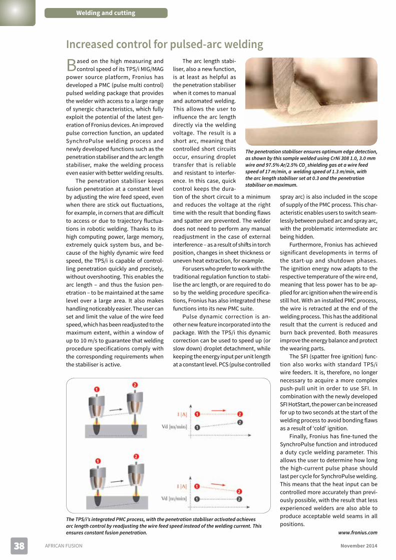
AFRICAN FUSION November 20143838
Welding and cutting
Based on the high measuring and control speed of its TPS/i MIG/MAG
power source platform, Fronius has developed a PMC (pulse multi control) pulsed welding package that provides the welder with access to a large range of synergic characteristics, which fully exploit the potential of the latest gen-eration of Fronius devices. An improved pulse correction function, an updated SynchroPulse welding process and newly developed functions such as the penetration stabiliser and the arc length stabiliser, make the welding process even easier with better welding results.
The penetration stabiliser keeps fusion penetration at a constant level by adjusting the wire feed speed, even when there are stick out fluctuations, for example, in corners that are difficult to access or due to trajectory fluctua-tions in robotic welding. Thanks to its high computing power, large memory, extremely quick system bus, and be-cause of the highly dynamic wire feed speed, the TPS/i is capable of control-ling penetration quickly and precisely, without overshooting. This enables the arc length – and thus the fusion pen-etration – to be maintained at the same level over a large area. It also makes handling noticeably easier. The user can set and limit the value of the wire feed speed, which has been readjusted to the maximum extent, within a window of up to 10 m/s to guarantee that welding procedure specifications comply with the corresponding requirements when the stabiliser is active.
The arc length stabi-liser, also a new function, is at least as helpful as the penetration stabiliser when it comes to manual and automated welding. This allows the user to influence the arc length directly via the welding voltage. The result is a short arc, meaning that controlled short circuits occur, ensuring droplet transfer that is reliable and resistant to interfer-ence. In this case, quick control keeps the dura-tion of the short circuit to a minimum and reduces the voltage at the right time with the result that bonding flaws and spatter are prevented. The welder does not need to perform any manual readjustment in the case of external interference – as a result of shifts in torch position, changes in sheet thickness or uneven heat extraction, for example.
For users who prefer to work with the traditional regulation function to stabi-lise the arc length, or are required to do so by the welding procedure specifica-tions, Fronius has also integrated these functions into its new PMC suite.
Pulse dynamic correction is an-other new feature incorporated into the package. With the TPS/i this dynamic correction can be used to speed up (or slow down) droplet detachment, while keeping the energy input per unit length at a constant level. PCS (pulse controlled
spray arc) is also included in the scope of supply of the PMC process. This char-acteristic enables users to switch seam-lessly between pulsed arc and spray arc, with the problematic intermediate arc being hidden.
Furthermore, Fronius has achieved significant developments in terms of the start-up and shutdown phases. The ignition energy now adapts to the respective temperature of the wire end, meaning that less power has to be ap-plied for arc ignition when the wire end is still hot. With an installed PMC process, the wire is retracted at the end of the welding process. This has the additional result that the current is reduced and burn back prevented. Both measures improve the energy balance and protect the wearing parts.
The SFI (spatter free ignition) func-tion also works with standard TPS/i wire feeders. It is, therefore, no longer necessary to acquire a more complex push-pull unit in order to use SFI. In combination with the newly developed SFI HotStart, the power can be increased for up to two seconds at the start of the welding process to avoid bonding flaws as a result of ‘cold’ ignition.
Finally, Fronius has fine-tuned the SynchroPulse function and introduced a duty cycle welding parameter. This allows the user to determine how long the high-current pulse phase should last per cycle for SynchroPulse welding. This means that the heat input can be controlled more accurately than previ-ously possible, with the result that less experienced welders are also able to produce acceptable weld seams in all positions.
www.fronius.com
The TPS/i’s integrated PMC process, with the penetration stabiliser activated achieves arc length control by readjusting the wire feed speed instead of the welding current. This ensures constant fusion penetration.
The penetration stabiliser ensures optimum edge detection, as shown by this sample welded using CrNi 308 1.0, 3.0 mm wire and 97.5% Ar/2.5% CO2 shielding gas at a wire feed speed of 17 m/min, a welding speed of 1.3 m/min, with the arc length stabiliser set at 0.3 and the penetration stabiliser on maximum.
Increased control for pulsed-arc welding

November 2014 AFRICAN FUSION 3939
In partnership with the Gauteng De-partment of Education (GDE), leading
gases and welding products group, Afrox, has invested more than R1-million in upgrading and resourcing the welding centres at five underprivileged technical high schools. The schools in-clude Katlehong Technical High School in Katlehong, Primrose High School in Germiston, Modiri Technical High School in Mamelodi, Missouri Second-ary School in Eldorado Park and Jabu-lani Technical High School in Soweto.
Through the GDE partnership, Afrox will provide learners with the opportu-nity to optimise their skills in the field of welding, which is currently a critically scarce skill in the country. The upgrading and resources partnership campaign was officially launched on 24 October 2014 at Jabulani Technical High School.
Afrox managing director, Brett Kim-ber says: “This partnership will provide the opportunity to improve knowledge and practical skills among teachers to enable them to deliver the full curricu-lum and enhance learner performance in mechanical technology.”
The five school upgrades took six months to complete and included
outfitting classrooms with welding equipment and consumables to conform to the highest of health and safety standards. Equipment investment covers a range of Afrox Transarc MIG inverter power sources and personal protective equipment as well as numerous consumables, such as electrodes and wires.
As part of its commitment to the partnership, Afrox will also fund extensive teacher training in the field of welding. These teacher-training programmes will provide additional support to the GDE’s ‘Turnaround Plan of Technical High Schools’.
The teacher training is an ac-credited 40-hour training programme scheduled over a ten-week period com-mencing in January 2015 and will take place at Afrox’s Demonstration Centre in Germiston.
Kimber confirms that Afrox is cur-rently in the process of upgrading an ad-ditional 14 schools nationwide, in order to support the Government’s economic and skills development in South Africa. Regions benefiting include the Eastern and Western Cape, Free State, Gauteng and KwaZulu-Natal. “Our long-term aim
is to offer bursaries to matriculants by entering into partnerships with techni-cal colleges nationwide. By creating awareness among school pupils, we want to encourage and promote a career in welding at grassroots level, through long-term partnerships,” he says.
The funding of this initiative is being facilitated through Sci-Bono Discovery Centre – a world-class science centre ini-tiated by the GDE that supports maths, science and technology education.
www.afrox.com
The first-of-its-kind SMOOTHFLO gas regulator boasts a number of world-leading safety features that have been
exclusively developed by sub-Saharan African gas market leader, Afrox – which officially launched the new range in mid-2014.
Developed over a two-year period at the Afrox manufacturing facility in Germiston, South Africa, SMOOTH-FLO features major breakthroughs in design, and is the first gas regulator in the world to come standard with a piston-embedded safety valve, as opposed to an externally mounted safety valve which is subjected to external conditions.
Afrox head of hard goods Nazmi Adams says that piston-driven technology produces excellent pressure stability at higher flow rates, which allows an operator to achieve greater gas cutting speeds. “The ability to go from zero to maximum operating pressure in just three turns reduces the amount of set-up time required,” he explains.
A new break-off inlet stem ensures that the high performing excess-flow valve will safely and automatically seal off gas discharge from a cylinder into the atmosphere, should it and the regulator accidently fall. This is a
major safety advantage for numerous industries that use oxy-acetylene for welding, which range from mining and fabrication to manufacturing and rail.
“Standard regulators with externally mounted pressure gauges can suffer damage from external impacts,” says Adams. The resul-
tant release of gas poses serious fire hazards as well as being costly to repair. The unique design of SMOOTHFLO makes the gauges almost entirely damage-proof, and minimises the threat of a catastrophic accident.
Discussing the reception received by the new technology in mature overseas markets, Adams says that SMOOTHFLO is “likely to be-come the new standard in the safety conscious global markets. Afrox is proud to be placing South Africa as a world leader in gas market safety through the development of SMOOTH-FLO, which boasts unrivalled performance.”
Looking to the future, he says: “In order to remain a market leader, Afrox is already researching the incorporation of smart tech-nology to allow for communication between the unit and machinery for even greater safety and efficiency.”
www.afrox.com
At Jabulani Technical High School, MD Brett Kimber (left in photo) launched Afrox’s R1-million upgrading and resourcing initiative for welding centres at five underprivileged technical high schools.
The SMOOTHFLO gas regulator has a break-off stem that shuts off the gas should the regulator be sheared off due to an external impact.
Welding: the perfect public private partnership
World-first in gas regulator safety and efficiency

November 2014 AFRICAN FUSION 4141
Change can be challenging, but when the potential benefits are compel-
ling enough – such as saving money and avoiding downtime – then it may be worthwhile to switch to new machinery. In this article, Unique Welding Alloys outlines the top five things to consider when making equipment decisions.
Determine the need for change: Usually, the most obvious sign of a need to change is when you consistently expe-rience extended downtime and no spare parts are available. Other signs it’s time to switch over are:• When the spare parts themselves
are excessively priced, raising the question of the financial sense of keeping a machine.
• If the same machinery has been used for many years. There’s noth-ing wrong with brand loyalty, but changes in the market and produc-tion output might call for an update to more modern machinery.
• If a new applications emerges re-quiring a new welding procedure. A good supplier will be able to customise a solution to best suit specific welding needs, shortening internal development times
Investigate and research: Some ques-tions to ask when looking at equipment options include: • Is the potential supplier available
for consultation? In other words, pick a supplier willing to meet , help troubleshoot and to provide real solutions.
• Does the new machinery have read-ily available spare parts and are they reasonably priced? There’s no point switching brands if the new machine is not easy to repair and maintain going forward.
• Is the new partner technically com-petent? No matter how simple the needs are, a supplier must have after-sales service and knowledge of how to get the best out of the equipment brand
Understand and accept long-term benefits: It’s obvious that the positives should outweigh the negatives, but it’s imperative to weigh up long-term benefits instead of short-term ones. For example, perhaps the initial cost of the new machinery is on the high side, but the long-term benefits of saving on
spare parts and reducing downtime may outweighs this, considerably. If a supplier believes in its brand offering as they should, they’ll be able to supply the new machines’ projected production output over the course of a year. As well as offering some comfort, this can also indicate just how technically competent a new supplier is.
Trials and tests: If a new machine can perform well, a supplier should be more than willing to trial the machine at a customer’s prem-ises for up to a month. The proof is in the pud-ding and if any doubts persist, then this trial period should be non-negotiable. It is also the easiest way to convince upper management and stakeholders of the ben-efits outlined in a invest-ment proposal.
Service and main-tenance: The impor-tance of after-sales ser-vice in terms of repairs and spare parts avail-ability cannot be over-emphasised. To achieve machine longevity and durability, however, regular servicing and upkeep are very impor-tant. Suppliers should be able to offer on-site maintenance with mini-mum downtime in order to keep machines in good working condition. Ideally, plan ahead with equipment suppliers and schedule regu-lar annual services. Prevention is always better than cure!
Weldamax/UWA successesWhen a sugar mill began looking to replace old machinery used to weld its hammers, it was offered a trial of the Thermamax 600 CC/CV welding machine. Not only did the machine fulfil all of the welding requirements, the supplier also assured the quality, service and price competitiveness of the product and spares. With over 18 machines supplied to various sugar mills nationally and across borders, there has
In addition to Thermamax, Weldamax also stocks over 3 000 welding products as well as all associated UWA consumables and accessories.
Unique Welding Alloys is a division of Weldamax and owns the Thermamax brand (previously Thermadyne).
Switch and save: Five considerations when switching equipment brands
been no machine failure in the four-year period since they began to be installed.
In a customisation success story, Weldamax partnered with an interna-tional supplier to customise and build a 2 000 A gouging machine for Metso Minerals. This single machine replaced two historic brands and, in the two years since its installation, the total mainte-nance costs have amounted to R2 400, making the total cost of ownership of this replacement far more cost effective than the ongoing maintenance of the older machines.
www.weldamax.co.za
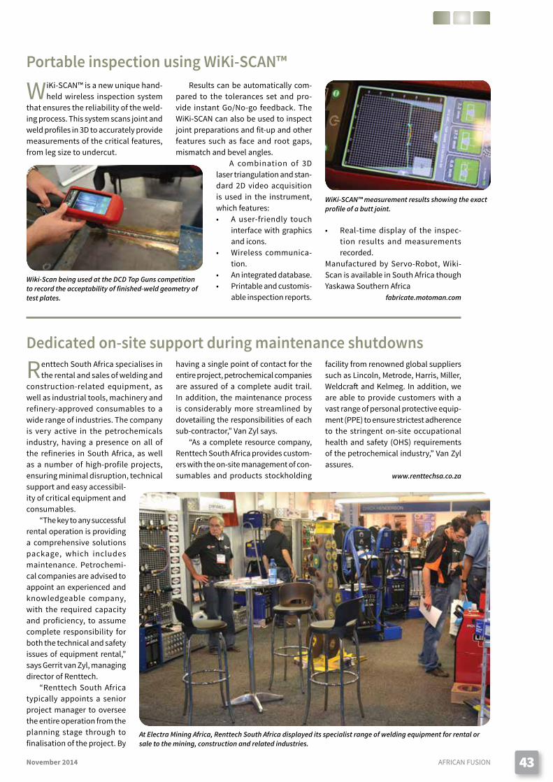
November 2014 AFRICAN FUSION 43
WiKi-SCAN™ is a new unique hand-held wireless inspection system
that ensures the reliability of the weld-ing process. This system scans joint and weld profiles in 3D to accurately provide measurements of the critical features, from leg size to undercut.
Results can be automatically com-pared to the tolerances set and pro-vide instant Go/No-go feedback. The WiKi-SCAN can also be used to inspect joint preparations and fit-up and other features such as face and root gaps, mismatch and bevel angles.
A combination of 3D laser triangulation and stan-dard 2D video acquisition is used in the instrument,
Renttech South Africa specialises in the rental and sales of welding and
construction-related equipment, as well as industrial tools, machinery and refinery-approved consumables to a wide range of industries. The company is very active in the petrochemicals industry, having a presence on all of the refineries in South Africa, as well as a number of high-profile projects, ensuring minimal disruption, technical support and easy accessibil-ity of critical equipment and consumables.
“The key to any successful rental operation is providing a comprehensive solutions package, which includes maintenance. Petrochemi-cal companies are advised to appoint an experienced and knowledgeable company, with the required capacity and proficiency, to assume complete responsibility for both the technical and safety issues of equipment rental,” says Gerrit van Zyl, managing director of Renttech.
“Renttech South Africa typically appoints a senior project manager to oversee the entire operation from the planning stage through to finalisation of the project. By
having a single point of contact for the entire project, petrochemical companies are assured of a complete audit trail. In addition, the maintenance process is considerably more streamlined by dovetailing the responsibilities of each sub-contractor,” Van Zyl says.
“As a complete resource company, Renttech South Africa provides custom-ers with the on-site management of con-sumables and products stockholding
Wiki-Scan being used at the DCD Top Guns competition to record the acceptability of finished-weld geometry of test plates.
WiKi-SCAN™ measurement results showing the exact profile of a butt joint.
At Electra Mining Africa, Renttech South Africa displayed its specialist range of welding equipment for rental or sale to the mining, construction and related industries.
Portable inspection using WiKi-SCAN™
• Real-time display of the inspec-tion results and measurements recorded.
Manufactured by Servo-Robot, Wiki-Scan is available in South Africa though Yaskawa Southern Africa
fabricate.motoman.com
which features: • A user-friendly touch
interface with graphics and icons.
• Wireless communica-tion.
• An integrated database.• Printable and customis-
able inspection reports.
Dedicated on-site support during maintenance shutdownsfacility from renowned global suppliers such as Lincoln, Metrode, Harris, Miller, Weldcraft and Kelmeg. In addition, we are able to provide customers with a vast range of personal protective equip-ment (PPE) to ensure strictest adherence to the stringent on-site occupational health and safety (OHS) requirements of the petrochemical industry,” Van Zyl assures.
www.renttechsa.co.za

AFRICAN FUSION November 201444
IND
EX T
O
AD
VER
TISE
RS Afrox ......................................................................6
Air Liquide .................................................. OFC, 20Air Products ........................................................29BED Holdings: Fronius .......................................IFCDCD Mining and Energy ......................................40ESAB ....................................................................10Lincoln Electric: Metrode ............................... OBC
Probraze Metals ..................................................24SAIW ......................................................................2Speciality Metals ..................................................9voestalpine Böhler Welding SA ..........................42WASA ................................................................. IBCWeldamax: Thermamax .....................................28Yaskawa Motoman .............................................37
Today’s technology
When corrosion becomes a major design consideration, the im-
portance of cladding technology as a possible solution, increases. A high quality clad solution can provide cor-rosion protection and be more cost effective than using a fully high-alloyed base metal. But, in order to guarantee optimal protection, the weld overlay quality is essential.
ALLOY 400 is a nickel-copper alloy (Ni-Cu) with good mechanical proper-ties and excellent resistance to many corrosive environments. Marine and chemical processing are the two main fields where Alloy 400 is used. While some applications require the use of
Alloy 400 base plate, in many cases it is more cost effective to clad a layer of the alloy onto carbon steel plate; that is, using a welding process to create a complete barrier layer of Alloy 400 on the surface of a substrate.
There are inherent difficulties asso-ciated with the use of Ni-Cu-based weld-ing consumables. The base metal analy-sis has to be taken into consideration to control the effect of base plate dilution. The dilution of Ni and Cu into Fe-based substrates can be accommodated at all levels; that is, all levels of dilution into the substrate can be accommodated without fear of cracking. If however, the substrate contains chromium, severe
hot cracking can occur if chromium dilution exceed 6-8% in the Ni-Cu weld de-posit. Dilution of the weld deposit with Fe also has a deleterious effect on Ni-Cu. Severe hot cracking can oc-cur if the iron content excess 15% in the weld deposit.
Four welding processes are predominantly used for joining and cladding applica-tions: GTAW; SMAW; GMAW and SAW, with the selection of any one technique depen-dent upon access; welding position; dilution; and pro-ductivity. The solid wire MIG process is one of the more productive processes (semi-automatic or automatic). However, the best compro-mise between quality and productivity has often come from the shielded metal arc welding process due to the oxidation protection created by a combination of the slag
and an accurate and controlled level of dilution.
Welding Alloys Group has developed a new basic flux-cored wire, GAMMA 400, with the weld metal composition of an Alloy 400. This cored wire brings together the productivity characteristics and benefits associated with solid wires and the quality and dilution benefit of shielded electrodes to provide higher levels of productivity and higher quality deposits than either of these processes.
A significant advantage of flux-cored wires over solid equivalents is the depo-sition rate. With the same wire diameters at the same operating parameters (215 A 25 V and 29 cm/min), flux-cored wire typically runs at wire feed speeds that are 36% higher than solid wires. This represents approximately 4.6 kg/h for the FCAW process compare to 4.0 kg/h for the solid wire.
Quality is also significantly improved by using cored wires. Using equivalent operating parameters, a cored wire will have the lowest dilution and give bet-ter weld pool protection thanks to the slag protection – and no trailing shield is needed. Using the same cladding parameters on carbon steel base metal, Ni-Cu solid wire (ERNiCu7) will have a high risk of hot cracking due to the high dilution rate in the 1G/PA position (~23% compared to 13% for basic cored wire). This translates into an iron content of 15% Fe for the solid wire as opposed to the 9.0% Fe if using the cored wire process (Figures 1 and 2).
Moreover, cored wires can be used with simpler technology and are gener-ally easier to use – no pulse technique is required and M21 shielding gas can be used. In summary, a manufacturer can increase productivity and quality by using a cored wire.
Ni-Cu cladding using basic flux-cored wireBastien Gerard, Welding Alloys Group
Figure 2: A clad layer of Alloy 400 deposited using the flux cored (ENiCu7 GAMMA 400) in the 1G/PA position. DC+, 215 A, 25 V, 29 cm/min.Dilution 13%. Percentage Fe in the first layer: 9%.
Figure 1: A clad layer of Alloy 400 deposited using the pulsed MIG process and solid wire (ERNiCu7) in the 1G/PA position. 215 A, 26 V, 29 cm/min.Dilution 23%. Percentage Fe in the first layer: 15%.