AFOSR 81 @@93 MARCH 2/3 SCEC 1984 TO A ANNUAL MARCH I …
182
D-A60 425 ANNUAL PROGRESS REPORT ON CONTRACT AFOSR 81 @@93 MARCH 2/3 SCEC A OH~ P 5UKPL815 1984 TO MARCH I (U) TENNESSEE UNIV KNOXVILLE PLASMA UNCLASSIFIED AFOSR TR-85-0870 AFOSR-81-0893 F/C 20/9 N NEFEEMEE IEN~ I mhmmmmmmoI
Transcript of AFOSR 81 @@93 MARCH 2/3 SCEC 1984 TO A ANNUAL MARCH I …

D-A60 425 ANNUAL PROGRESS REPORT ON CONTRACT AFOSR 81 @@93 MARCH 2/3
SCEC A OH~ P 5UKPL815 1984 TO MARCH I (U) TENNESSEE UNIV KNOXVILLE PLASMA
UNCLASSIFIED AFOSR TR-85-0870 AFOSR-81-0893 F/C 20/9 N
NEFEEMEE IEN~
I mhmmmmmmoI

1j.
I..
,.o
Ku __ U
mli I 40 -
111L2 =.6
MICROCOPY RESOLUTION TEST CHARTNATIONAL BUREAU OF STANDARDS- 1963-A

A CALIBRATED, BROADBAND ANTENNA FOR PLASMA RF EMISSIONMEASUREMENTS BELOW 1 GHz*
Paul D. SpenceDepartment of Engineerin3 Science and Mechanics
anDavid Rosenberg
J. Reece RothDepartment of Electrical Engienering
University of TennesseeKnoxville, Tennessee 37966-2100
A constant impedance, constant aperture antenna can make possible
broadband plasma RF emission measurements which yield relative and
absolute power levels. However, good technique, such as that described by
Heald and Wharton [11, must be followed for the immersion of such an RF
* probe into plasma radiation.
We have used a complementary conical spiral antenna, similar to that
described by Rumsey [2], to observe plasma RF emission over the frequency
range 100 5 v!!_ 1200 MHz. The RF emission was emitted bya modified
Penning discharge as described by Roth [31 and Roth, Hayman, and Pastel [4].
The RF emission from the discharge typically exhibits harmonic structure over
a broad frequency range, necessitating a broadband antenna with a flat
frequency response curve to allow detailed spectral analysis.
The antenna consists of two metal strips of approximately uniform
th width wound helically on a cone made of Lexan plastic. Since the antenna is a
. balanced network, a balun is employed to make the transition to a 50-ohm
coaxial line. The antenna feed methods is critical in maintaining a uniform
*Supported in part by ONR Contract #NO0014-80-C-0063 and in part byI *y AFOSR contract #81-0093.
-B-4

impedance network. Neglecting stray transmission line effects, the probe
0 " 0circuit for the frequency range 100 < v <500 MHz is 50 ohms due to the
spectrum analyzer, paralleled by 291 ohms due to balun magnetization; the
combination is fed by a 144 ohm probe aperture (see Fig. 1). Above 500 MHz,
. the balun seem to behave nonuniformly and requires further fine tuning to
achieve a satisfactory frequency response and an accurate calibration over
the frequency range from 500 MHz to 1.0 GHz. Below 100 MHz, it is not clear
that the antenna remains properly immersed in the plasma radiation under
present laboratory conditions.
antenna balun spectrumaperture loss analyzer
- 1440 291 Q 500
Figure 1
"4, REFERENCES
-. 1. M. A. Heald and C. B. Wharton, Plasma Diagnostics With Microwaves,Krieger Publishing, New York, 1978.
2. V. Rumsey, Frequency Independent Antennas, Academic Press, NewYork, 1966.
3. J. R. Roth, Modification of Penning Discharge Useful in Plasma PhysicsExperimeents, RSI, 37 (1966), 1100-1101.
.4.4
4. J. R. Roth, P. W. Hayman, and R. L. Pastel, A Paired Comparison of HighIL Frequency RF Emission from Two Configurations of Electric Field
Dominated Plasma, Proc. 1982 Int. Conf. on Plasma Physics, Goteborg,Sweden.
B-5
0)'~it 1 0; &O

Introduction -
Log spiral and log periodic antenna structures can be constructed to
operate over multioctave frequency bandwidths. M The log spiral and other
:types of spiral antenna are exploited in broadband radar technique and in
direction finding.1 21 Their constant impedance and uniform aperture due to
complementary structure make them well suited to broadband, far fiel RF
21 plasma emission measurements.
A complementary antenna structure is one in which there is equal share
of conductor and dielectric area on the radiating surface (see Figure 1).
2: The impedance of such a structure is theoretically one half that of free space,
188 ohms. In practice an impedance of about 160 ohms is found.131 A major
limit in exploiting full bandwidth of a given structure is the matching of the
antenna impedance to that of (usually) a 50 ohm system. That is, when using
a spiral antenna for plasma diagnostics the uniform impedance of the
antenna and the uniformity of pattern shape must be maintained over large
bandwidths, otherwise antenna resonances will introduce false RF spectral
responses, and yield distorted measurements.
Low frequency limits of spiral antennae are usually set by the maximum
diameters of the structures; presumably one quarter of a longest received: wave length. 131 For low frequencies, s ay 50 MHz, a structure at least 1.5
meters in diameter is required. Most laboratory conditions make this
impractical • However by suitable end loading, low frequency limits of
smaller structures can often be extended.
i
5-6
6 w 2;)a
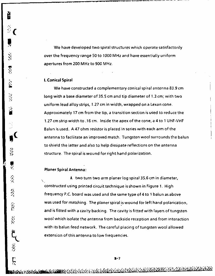
We have developed two spiral structures which operate satisfactorily
" over the frequency range 50 to 1000 MHz and have essentially uniform
apertures from 200 MHz to 900 MHz.
x I. Conical Spiral
We have constructed a complementary conical spiral antenna 83.9 cm
-'.- long with a base diameter of 35.5 cm and tip diameter of 1.3 cm; with two
uniform lead alloy strips, 1.27 cm in width, wrapped on a Lexan cone.
Approximately 17 cm from the tip, a transition section is used to reduce the
1.27 cm strip width to.16 cm. Inside the apex of the cone, a 4 to 1 UHF-VHF
Balun is used. A 47 ohm resistor is placed in series with each arm of the
antenna to facilitate an improved match. Tungsten wool surrounds the balun
to shield the latter and also to help dissipate reflections on the antenna
structure. The spiral is wound for right hand polarization.
Planer Spiral Antenna:
A two turn two arm planer log spiral 35.6 cm in diameter,
constructed using printed circuit technique is shown in Figure 1. High
-. frequency P.C. board was used and the same type of 4 to 1 balun as above
was used for matching. The planer spiral is wound for left hand polarication,
and is fitted with a cavity backing. The cavity is fitted with layers of tungsten
-: wool which isolate the antenna from backside reception and from interaction
with its balun feed network. The careful placing of tungsten wool allowed
extension of this antenna to low frequencies.
B-7
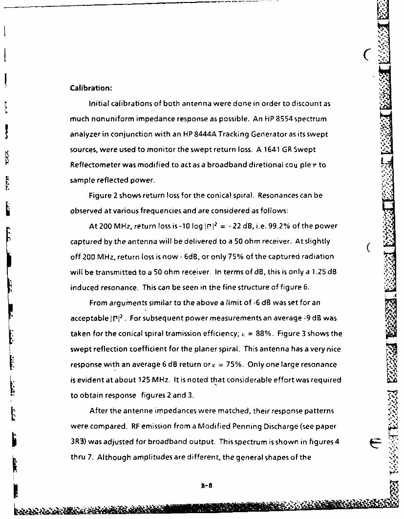
ClCalibration:
Initial calibrations of both antenna were done in order to discount as
much nonuniform impedance response as possible. An HP 8554 spectrum
analyzer in conjunction with an HP 8444A Tracking Generator as its swept
sources, were used to monitor the swept return loss. A 1641 GR Swept IReflectometer was modified to act as a broadband diretional cou pler to
sample reflected power.
Figure 2 shows return loss for the conical spiral. Resonances can be
observed at various frequencies and are considered as follows:
At 200 MHz, return loss is -10 log I r' 2 = -22 dB, i.e. 99.2% of the power
captured by the antenna will be delivered to a 50 ohm receiver. At slightly (off 200 MHz, return loss is now - 6dB, or only 75% of the captured radiation
will be transmitted to a 50 ohm receiver. In terms of dB, this is only a 1.25 dB
induced resonance. This can be seen in the fine structure of figure 6.
From arguments similar to the above a limit of -6 dB was set for an
acceptable i i 2 . For subsequent power measurements an average -9 dB was
taken for the conical spiral tramission efficiency; L = 88%. Figure 3 shows the Iswept reflection coefficient for the planer spiral. This antenna has a very nice
response with an average 6 dB return or = 75%. Only one large resonance
is evident at about 125 MHz. It is noted that considerable effort was required
to obtain response figures2 and 3.
After the antenne impedances were matched, their response patterns
were compared. RF emission from a Modified Penning Discharge (see paper
3R3) was adjusted for broadband output. This spectrum is shown in figures 4 ..%.'
thru 7. Although amplitudes are different, the general shapes of the
B-8 -
%.~

emissions in figures 4 and 5 are quite similar. Enlargement in figures 6 and 7
shows very good agreement of the harmonic structure of the emission. Fne
structure inlr!, 2 of the conical spiral (figure 2) now shows up as fine structure
on figure 6.
Effective Apperture:
The effective aperture of an antenna is an area that corresponds to the
effective capture area for incoming radiation. This area is dependent on the
antenna structure as well as polarization of the incoming radiation and
reflections.
In order to calibrate the effective aperture, the broadband radiation
pattern of the plasma from 700 Hz to 1200 MHz was investigated using a
ridged horn terminated in a thermistor power meter. In this frequency range
the plasma was found to behave as a cylindrical radiator. A standard half
wavelength dipole taken from an Empire Devices field strength set was then
used to determine that RF radiation was linearly polarized with the E plane
parallel to the static B field of the plasma. This agreed with polarization
indicated by the ridged horn.Figures 8 and 9 show plasma emission detected by the conical spiral and ii'
planer spiral antennae respectively for effective area calculation. By the
procedure employed, detected power flux in a given bandwidth, using a
standard half wave dipole, was compared to power detected by each spiral
antenna.
The effective aperture of a half wavelength dipole was taken to be
Aeff 0.13'\2.

Power measurements from 100 MHz to 1000 MHz in 100 MHz intervals where
taken for each the dipole and the two spirals. RF power captured by each
antenna was measured over a 10 MHz bandwidth about the center frequency
with a 300 KHz sampling bandwidth. For the dipole a polarization and
scattering loss of 1 dBm was added to these measurements and for the spirals
3 dBm was added to account for the linear polarization mismatch to a
circularly polarized antenna. Cable losses were also considered as was ir I2
measured at each frequency for each antenna. Effective aperture as a
function of frequeny for the three antennae is shown in figure 10.
A distance correction was also included in calculating the effective
apperature. We tried to maintain a spacing of at least one wavelength -
S between antenna. This is slightly violated at 100 MHz. Do to this spacing
however the dipole and the spirals were not at the same distance from the
plasma. This correction was taken to go as l/r rather l/rdo to the laboratory
radiation environment.
Results:
The plasma emission to be detected by these antennae is usually inthe
frequency range of 100 MHz to 1000 MHz with the peak of the emission
envelop from 300 MHz to 900 MHz. Consequently we take from figure 10 a
mean effective aperture for each antenna as:
Aeff (Conical Spiral) = 633 cm2'
i=" Aeff (Planer Spiral) =143 cm2
D5-10
IN N-, x

From figures 2 and 3 we take a mean power transmission efficiency for
the two antennae as
cm (Conical Spiral) = 88%0'
em (Planer Spiral) = 75%
These results in conjunction with polarization mismatch and cable losses
are what we need for net rF power measurements of the plasma discharge
(see paper 3R3).
The effective aperture's can be compared to the actual antenna
surface's of
Area conical spiral = 4682 cm 2
Area planer spiral = 993 cm 2
Thus, effectie aperture of the conical spiral is 13.5% of its total surface area
where as effective aperture of the planer spiral is 14.4% of its total area.
Conclusions:
We have developed two spiral antennae which operate over the
- frequency range of 50 MHz to 1000 MHz and which can be used for detailed
RF spectral data analysis of broadband far field power fluxes. The right hand
and left hand polarizations of the two antennae allow additional
information of the plasma's emission. ..
The calibration of the antenna has allowed us subsequently to
determine local R.F. power flux measurements to within an order of flmagnitude.
-A
5-11

. -= . r .... ... . .,,. . . . . : -7 t, : Jrrr -. -- ,- - - °u-z o~' v-v - v ,-,vv. - . - . • - -" - . .. .
IC
REFERENCES
1. V. Rumsey, " Frequency Independent Antennas, Academic Press." New
York, 1966.
- 2. J. A. Mosko, "An Introduction to Wideband Two-Channel Direction-
*Finding Systems" Microwave Journal Feb., 1984.
3. Theile, Stutzman, "Antenna Theory and Design", Wiley, 1981.
m(
-
B-12
iqYk.

FIGURE I
CONICAL SPIRAL PLANER LOG SPIRAL
B-13

- . *. FIGURE2
,REYFLECTON* COE F. M QICAL SPRAL
10dB/div.
* dB -ref .
- 0500MHz 10,00(
FIGURE 3REFLECrION COEF. - PLANAR SPIRAL
lOdB/dijy.
Id ref
.j I
8-1 0j to5o-Jr.

",p'
"FIGURE 4 FIGURE 6
.:,..'RF SPECTRUM C CONICAL SPIRAL RF SPECTRUM CONICAL SPIRAL
.80dB .
,0 500MHz 1000 100 200 MHz 300
10dB/div for above O.ImV/div for above
• fIGURE 7-FIGURE 5 .F SPFCTRIIM PLAN A R SPIRAL --.
RF. SPECTRUM - PLANAR SPIRAL
,"80dB-1(. q500MHz 1000 100 200MHz 300 -,
10dB/div for above 2OuV/div. for above
-".- :. ... T. . '..
D L J -.. - . ,,, . . . ...
d . .- -- . .. , .C.€ , .. ; ' :..; . .
- ~ ~ ~ ~ ~ 9 15;.~::*'. . . . . ... - -.-. . ,, ,, , '..- ,. , .'. "- "- .- v- ."/ ',-'.'. ', . --. " " ." ." ,',,',,,*.- ,,\' ,".'-." ,1.
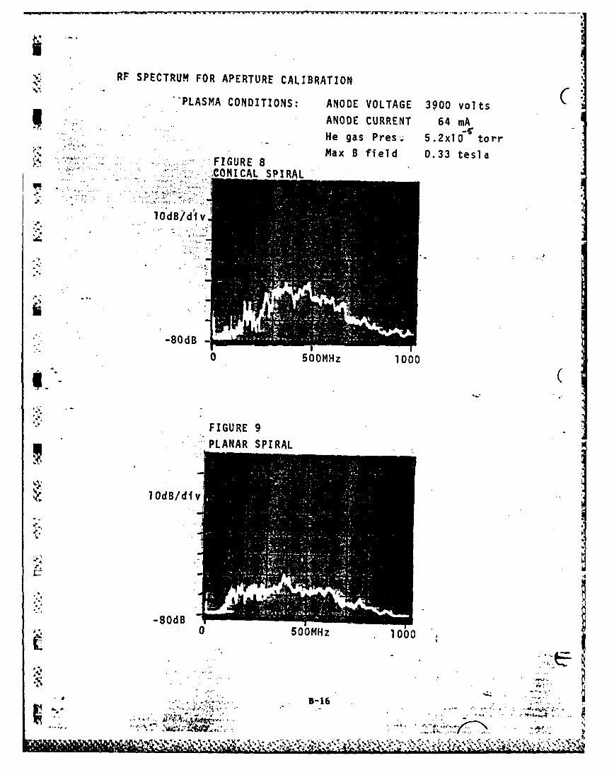
RF SPECTRUM FOR APERTURE CAL.IBRATION
'PLASMA CONDITIONS: ANODE VOLTAGE 3900 volts
ANODE CURRENT 64 mAHe gas Pres,; 5.2xl0 torrMax B field 0.33 tesla
* **~ -- CONICAL8SPIRAL
10dB/div1
0500MHz 1000
FIGURE 9PLANAR SPIRAL
-80dB o m0 500MHz 1000
.9 ,. .. -16
-s .. J~- ~ *
~ - *

GRAPH 1
I ' I *
DIPOLE (THEORETICAL) %.
10CONICAL SPIRAL 0PLANAR SPIRAL
,,.'•(METERS2 )
0.01
: . 0 00
200 400 600 800 1000FREQUENCY (MHZ)
*B-1
•.4. . '
• . f ,'

THE MODIFIED PENNING DISCHARGE
Cp
p -
N
CSI.
L.
hr
ENERGY ANALYZER
NV.
B- 18
...............................................................................................
~* .5 ,-* -~

CORRELATION OF RF EMISSION, PLASMA WAVE PROPAGATION, AND
PLASMA TURBULENCE IN CLASSICAL AND MODIFIED PENNING DISCHARGES
J. Reece Roth, Paul D. Spence, Larry R. Baylor,David Rosenberg, and Peyman Dehkordi
Plasma Science Laboratory
University of TennesseeKnoxville, Tennessee 37996-2100, USA
AbstractWe have taken data from two versions of the Penning discharge which
contain highly turbulent, electric field dominated plasma with densities up
to 3 x 10¹⁰/cm3. Auto and cross-correlation techniques were used to obtain
information about the turbulence and wave propagation in this plasma
from capacitive probe and microwave scattering signals.
1. Introduction
We have performed a paired comparison experiment on steady statem ( plasma created in classical [11 and modified Penning discharges [2] in
uniform and magnetic mirror geometries, respectively. Our classical
Penning discharge consists of a uniform magnetic field up to 0.40 Tesla, andour modified Penning discharge of a 5.7:1 magnetic mirror ratio with amaximum magnetic field on the axis up to 0.40 Tesla. The electrons are
trapped in an axial electrostatic potential well, and in both cases form aplasma about 10 cm in diameter in the midplane. The electron porilation
forms two interpenetrating beams in the background plasma which give riseto the geometric mean and other plasma instabilities [3,4]. These plasmas
support high levels of electrostatic turbulence, axial electric fields up toseveral hundred volts per centimeter, and emit broadband electromagneticradiation over the frequency range from below 1 MHz to more than 2 GHz
L [4,5,61. These plasmas draw anode currents up to 0.5 amps at up to 7.0 kV
anode potential, and characteristically have densities that range from below108/cm3 to above 5 x 10¹⁰. Characteristic electron kinetic temperatures
observed with Langmuir probes range from 5 to 300 eV.
C Data have been taken from both discharges with an analog-to-digitaldata handling system which allows us to analyze the digital time series
Preoared for presentation at the 1984 International Conference on Plasma
Physics, Lausanne, Switzerland, June 27-July 3, 1984.
3-19
'W ' ) ? , ' t) .''' ".i ,.'L, .'- -"/ T :. ,. " .',,',; '- -, ". .. ..

generated by electrostatic potential fluctuations detected by capacitiveprobes at two azimuthal or axial positions in the plasma. Auto- and cross-
power spectra, the phase coherence spectrum, and dispersion relations have
been observed for both plasmas. Rotating spokes, driven by E/B drift, and
propagating waves have been observed and their dispersion relations
obtained. These electrostatic potential fluctuations have been compared'-" and correlated with microwave scattering results from the classical Penning
discharge plasma.RF emissions over the frequency range from 100 to 1400 MHz have
been measured in the far radiation field with a spectrum analyzer connectedto a specially calibrated broadband conical spiral antenna. The plasmas emit
~radiation with numerous harmonics of a fundamental frequency over a
broad frequency range up to at least 2 GHz [4,5,61. We have also used our
antenna to make local power flux and net radiated power measurements.
Axial ion energy distribution functions were measured with a retardingpotential energy analyzer in both discharges, and varied frommonoenergetic to Maxwellian with characteristic energies from below 100
eV to several keV. High levels of electrostatic turbulence resulted in morenearly Maxwellianized energy distributions. The modified Penning
discharge seemedto produce more nearly Maxwellianized distributionfunctions than the classical Penning discharge, with its flat axial magneticfield profile. In both discharges, profiles of plasma potential and electron
number density and kinetic temperature were taken along the axis of
symmetry with a Langmuir probe under a variety of operating conditions.
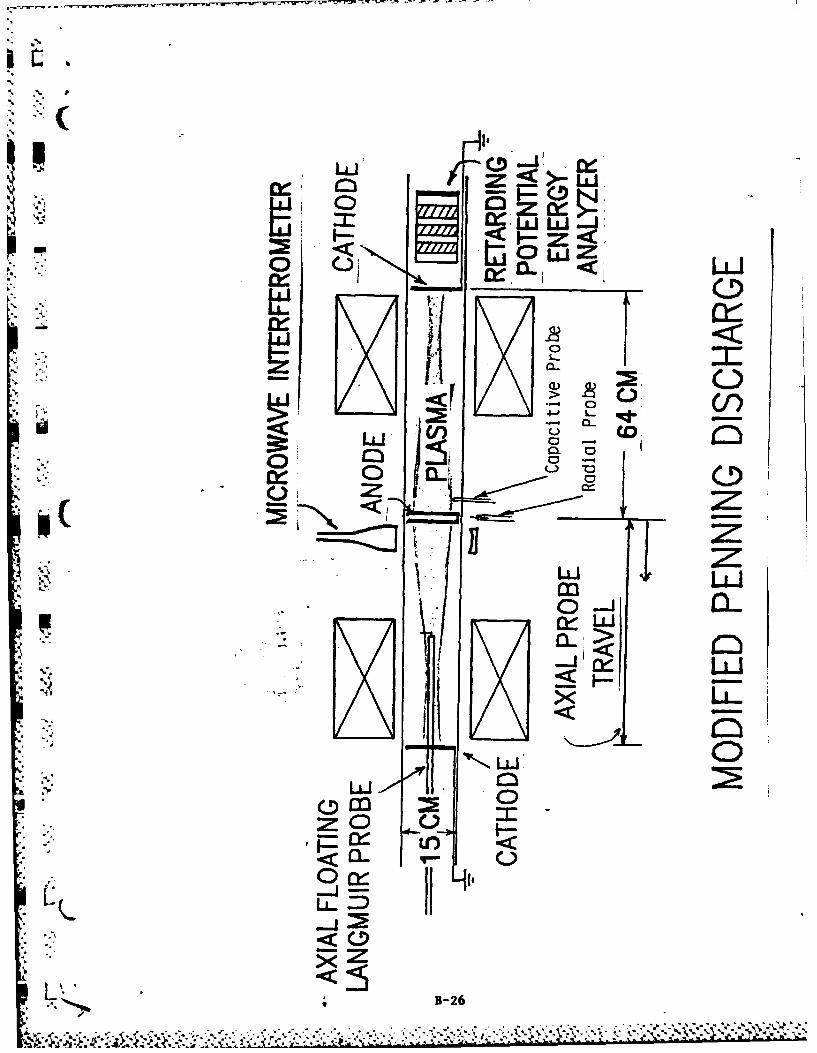
2. The Modified Penning Discharge UWith helium gas at pressures above 2 x 10⁻⁴ Torr, the axial profile of
electrostatic potential was quite flat, with axial electric fields of only a few
volts per centimeter at most. Below 10-4 Torr, however, electric fields up to
100 volts/cm were observed. On Fig. la is an example of a monotone
decreasing axial potential profile for a gas pressure of 4 x 10⁻⁵ Torr of
helium, Bmax = 0.15 Tesla, anode voltage Va = 4700 volts, a maximumnumber density on the midplane of 1.2 x 10⁸/cm3, and a characteristic Te =
60 eV. On Fig. lb is an interesting example not only of strong axial electricfields, but of an axial electrostatic potential well for ions, about 600-800 eVdeep. The helium gas pressure and magnetic field were approximately twice
that of Fig. la; Te 300 eV, and other parameters were approximately the
1-20

N ou . naI V. (..tJ
hlln~fdblve &Mro IS%
004 Fsv ,e am $
low.
Is 3 0 00 I so Anode A 1 O s an t. (cm ) I Cathode IN 0 . .3 ,c,Anod, SO 20 "30 0 | 0 so O
N .* IA Axial Cksla c~e a ( €rn)
A"mPrakof pneW Pg.4. 6'1- , Hegas rw.$IsIj.$1m . v..... * 4,olgom A.ii e- PWO. aPOm*ft Pg & .4. Is •t. N
ll 3.0 kdq..n . 4m wafte~
same. Both plasmas were highly turbulent, and the energy of ions escapingto the cathodes (measured with a retarding potential energy analyzer) wereon the order of kilovolts. The high axial electric fields observed imply a veryhigh anomalous resistivity for the plasma. This plasma emits multipleharmonics of a fundamental frequency which appears to be the geometricmean emission frequency associated with the interpenetrating beam plasmag ( instability [3]. The envelope of these harmonic peaks has a maximum whichis consistent with the electron plasma frequency of this discharge.
3. The Classical Penning DischargeThe classical Penning discharge also emits broadband RF radiation and
under certain circumstances, the spectrum is white-noise like from 0.6 MHzto above 1.0 GHz [4]. Significant radiation has been observed above 2.0GHz. Harmonics of the geometric mean emission frequency are observed,with a maximum envelope amplitude near the electron plasma frequency.
Measurements from a microwave scattering apparatus consisting of a27 GHz Gunn diode in a homodyne mixer configuration were taken.Approximately 100 milliwatts of microwave power was incident on theplasma in the ordinary mode. The scattered power is observed in a planenormal to the plasma axis for scattering angles from 200 to 160". When thescattered signal from the crystal detector is fed into a spectrum analyzer,electron number density fluctuations from 10 to 40 kHz are observed. Theseappear to obey a linear dispersion relation. On Figure 2a is shown anexample of the spectrum of microwave scattering signals for argon gas at a
B-21

10'1 Auto Power SPectfm 103Auto Power Spectrum
Ia-,
104
- .0
10-
0.o 10.00 20.00 30.00 40.00 0.00 10.00 20.00 30.00 40.00 50.0
Waefrequency K14z Wavet Frequency 1CM:
Figure 2A 7iue2Figure 2B
pressure of 3.5 x 10 4 Torr, at an anode voltage of Va = 1.1 kV, and a
magnetic field of B = 0.25 Tesla. On Figure 2b is an example of the auto
power spectrum taken under the same operating conditions from a
capacitive probe about 3 cm outside the plasma boundary. This shows no
( peak in the range from 10 kHz to 50 kHz.
AcknowledgementsThe classical Penning discharge investigations were supported by
AFOSR contract #81-0093, and the modified Penning discharge research by
ONR contract #N00014-80-C-O0 6 3.
References1 9 Penning, F. M.: and Nienhuis, K.: Philips Technical Review 11 No. 4
2. Roth, J. R.: RSl 37, No. 8.8, Aug. 1966, pp. 1100-1101.3. Alexeff, I.; Roth, J. R.; Birdwell, J. D.; and Mallavarpu, R.: Physics of
Flud Vol. 24, No. 7,1348-1357(1981).4. Roth, J. R.; Hayman, P. W.; and Pastel, R. L.: Proceedings of the
International Conference on Plasma Physics, Goteborg, Sweden, June9-15, (1982) p. 250.
5. Spence, P. D.; and Roth, J. R.: "Axial and Radial Profiles of PlasmaParameters in an RF-Emitting Modified Penning Discharge", APSBulletin, Vol. 28, No. 8, p. 1256-1265, (1983).
* 6. Pastel, R. L.; and Roth, J. R.: "Axial Electric Fields and Electron NumberDensity Profiles in a Classical Penning Discharge", APS Bulletin, Vol. 28,No. 8, pp. 1256-57 (1983).
5-22
0 .... .L " .. "

4A .~ r
4
Lo z< Z 00
CA. 00
z MU
LLI
- c
-: 0. (D
a. M01 0~
a. 0 cai co
0-. 4- 0 .m V-. %0- -C
8. -0 w w C
vio a. w OC
01(U AC A ru40 'A m
1 L >SI 4- (
EU 0 Lc
> C mU'.LL..A (D U) 0 L0 -a) M c %A(
Sz w
40
C -0
ACL
%A-I
M1-234

CORRELATION OF RF EMISSION, PLASMA WAVE PROPAGATION, AND PLASMATURBULENCE IN CLASSICAL AND MODIFIED PENNING DISCHARGES*
J. Reece Roth, Paul D. Spence, Larry R. Baylor,David Rosenberg, and Peyman Dehkordi
Plasma Science LaboratoryUniversity of Tennessee
Knoxville, Tennessee 37996-2100, USA
ABSTRACT
We have operated steady-state classical and modified Penning dis-charges in uniform and magnetic mirror geometries respectively [1]. Theclassical geometry consists of a uniform magnetic field up to 0.40 Tesla,,and the modified Penning discharge of a 5.7:1 magnetic mirror geometrywith a maximum magnetic field on the axis up to 0.40 Tesla. The elec-trons are trapped in an electrostatic potential well, and in both casesform a plasma about 10 cm in diameter in the midplane, and about 70 cmlong. The electron population forms two interpenetrating beams in thebackground plasma which give rise to the interpenetrating beam and otherplasma instabilities [2]. These plasmas support high levels of electro-static turbulence, axial electric fields up to several hundred volts percentimeter, and emit broadband electromagnetic radiation over the fre-quency range from below 1 MHz to more than 2 GHz [3].
We have applied a 27 GHz microwave scattering apparatus to theclassical Penning discharge. Electron number density fluctuations areobserved in the range from 10 to 40 kHz. Data have been taken from bothdischarges for various plasma operating conditions with an analog-to-digital data handling system which allows us to analyze the digital timeseries generated by electrostatic potential fluctuations detected bycapacitive probes at two azimuthal or axial positions in the plasma.Auto power spectra, cross power spectra, the phase coherence spectrumand dispersion relations have been observed for both plasmas. Rotatingspokes and other propagating waves have been observed, and their dis-persion relations obtained. These fluctuations have been compared withthe microwave scattering results from the classical Penning discharge.
RF emissions over the frequency range from 50 to 1400 MHz have beenobserved in the far radiation field with a specially developed broad-band conical spiral antenna. The plasma emits radiation with numerousharmonics of a fundamental frequency over a broad frequency range up toat least 2 GHz. We have also used our antenna to make local power fluxand net radiated RF power measurements. The RF emission spectra arecompared with the results of the propagating wave and turbulence data6%from the capacitive probes on both Penning discharges, and also with themicrowave scattering data from the classical Penning discharge.
*Supported by ONR contract N-00014-80-C-0063 and AFOSR contract 81-0093.
[1l J. R. Roth, RSI, 37, (1966) 1100-1101.(2] I. Alexeff, J. R. Roth, J. 0. Birdwell, and R. Mallavarpu, Phys.Fluids, 24, (1981), 1348-57.[3) J. R. Roth, P. W. Hayman, and R. L. Pastel, Paper 11P-II-02, Proc.1982 International Conf. on Plasma Physics, Goteborg, Sweden, p. 250.
B-24

r)"O 0
(I)U.5 V) Z5< V)
0 uajU
C!) z
0 ~ 1z -ow -0
uij
F-iLI-~ ~~8 ff-bJj iaf Zt
1-25j
LLiI
CL!
*<~ IC.oC-(C)*
LuU0m 0
.-.-.- j L. '.-. .
* -4 4
1-L
<0<
5Z
1.7B- -26

070
r7
wo

IV,
21P77 7 _
-~ . ~ .1 __ ___
_ _ _ _ I t_ _ _ _ I d
-77 i-77
9 .. . .. . ._
7Z-_ :7 . i k _
. ... .. ..
7~~ e - --- ....
-4
--- ----- -- -- -- -
B-2

MODIFIED PENNING DISCHARGE
ELECTRODE CURF ENT-'IAMILUIAMPS 17i. .. i--.-*--i.-
20 -
102 _______ 1 ;310ELCTOD -OTG (VOLTS)___ ii
B-29_____ ---- - _____

I a4
LA
'A. . ~ . uA
UCD
7x1.co
.144-
*i m
.q.a
1-30

RUN # ANX
100
80
p60 -RED
VOLTAGE o
RESPONSE B
.aJ(ARB. UNITS)
8.-
V..
6 --
10 20 40 60 80 100 200
FREQUENCY KHZ
RED: MICROWAVE SCATTERINGBLUE: CAPACITIVE PROBE AT MICROWAVE
B-31
,- I..'

x
t;
L
C CD
In00
uU IA
wttf
1-32-

RUN AOE AUTO POWER SPECTRA
100
80
VOLTAGERESPONSE 40
* (ARB. UNITS)
GREEN
20
4"4
1:1
2 -I.
10 20 40 60 80 100 200 "
FREQUENCY kHz
GREEN: CAPACITIVE PROBE AT MIDPLANE
BLUE: CAPACITIVE PROBE AT MICROWAVE SCAT.
RED: MICROWAVE SCATTERING
.-33
-" 44
4-
I-IMF
of3

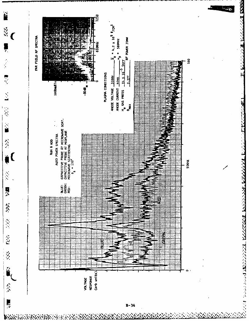
RUN # AOD
100 -BLUE
80
60
GREEN -
L VOLTAGE 40
RESPONSE9
,(ARB. UNIT)
RED
20
( 10
44
2
10 20 40 60 80 100 200FREQUEN'CY ki-z
GREEN: CAPACITIVE PROBE AT MIDPLANEBLUE: CAPACITIVE PROBE AT MICROWAVE SCAT.RED: MICROWAVE SCATTERING
B-35 -
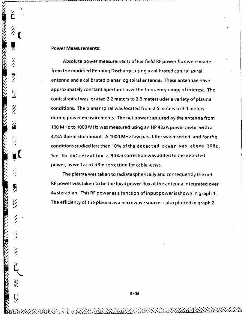
p Power Measurements:
Absolute power measurements of Far field RF power flux were made
from the modified Penning Discharge, using a calibrated conical spiral
antenna and a calibrated planar log spiral antenna. These antennae have
approximately constant apertures over the frequency range of interest. The
conical spiral was located 2.2 meters to 2.9 meters uder a variety of plasma
S",conditions. The planar spiral was located from 2.5 meters to 3.1 meters
during power measurements. The net power captured by the antenna from
100 MHz to 1000 MHz was measured using an HP 432A power meter with a
478A thermistor mount. A 1000 MHz low pass filter was inserted, and for theconditions studied less than 10% of the detected oower was above 1GHz.
Due to ociar zation a 3dBm correction was added to the detected
power, as well as a I dBm correction for cable lesses.
- . -The plasma was taken to radiate spherically and consequently the net
RF power was taken to be the local power flux at the antenna integrated over
4,, steradian. This RF power as a function of input power is shown in graph 1.
The efficiency of the plasma as a microwave source is also plotted in graph 2.
B-36
sA k' Z

FIGURE I
10
'.5.
CONIAL SIRALPLANER LOG SPIRAL
B-3

0-3

-iK
FIGURE 4 FIGURE 6RF SPECTRUM -CONICAL-SPIRAL
RF SPECTRUM -CONICAL SPIRAL
*It'll
rr
.8 0
10dB/div for above 0 lmV/div for above
FIGURE 7
P FIGURE 5 RF7 SPFc.TR'P4 PLANAR SPIRAL* RF SPECTRUM -PLANAR SPIRAL
10dB/div for above 2OuV/div. for above
B-39

GRAPH 4
INTEGRATED RF POWER VS. ELECTRON NUMBER DENSITY
,a ' I ... -
400 o
INTEGRATED 0 -
RF POWERflW 20 ),
* 0 2
S100 A 0- _ A
80-
60s
40-
20 1 . I I I
* 1 2 4 6 8 10 20
ELECTRON NUMBER DENSITY,: ~X 109 /ICm3 .
0 PLANAR SPIRAL V4
A CONICAL SPIRAL
.-. B-40

I
RDAIGEFCEC INTEGRATED RF POWERRADIATING EFFICIENCY =INPUT PLASMA POWER
- vs
INPUT PLASMA POWER
-' I I I ' |,
Li"
0.10
0.08
0.06 0RADIATING A )
EFFICIENCY IN %
0.04 .
6A
0.02 ,
0.01 , I ,
60 80 100 200 400 600 800 1000
INPUT POWER TO PLASMA (WATTS)
0 PLANAR SPI RAL
A CONICAL SPIRAL
5-41
22
CAPACITIV VALVEE N
[OARION
-PE
ANOD
CATHODE
0-5 k
POWER
80

117
fi-4 3
24
0O.2- ND
CA
w LOCATION CATHODE
w 0.1 L
0-e0 -60 -40 -20 0 20 40 60 80
AXIAL DISTANCE (cm)
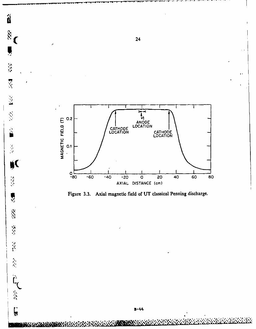
Figure 3.3. Axial magnetic field of UT classical Penning discharge.
B-44

( 31
WAVE
2kANALMAZEHITRECORDERNI
MIXE
-3 3-45TA IO TETOI H-05

INSiIt WC* . .ANN

( 42
PO0 5.5 x 10 orr
IP =100 mA
VA =1.2 W
.0 -3
0.3
w 020a.
0.2
wI0.2
0.20
.051
FREQUENCY (kHz)
Figure 4.4. Comparison of turbulence frequency spectra on magneticfield strength.
Il-
3-47_
re~

43
100
80
SLOPE =226 x 103
z
U
040
48 X10 3
010 0.1 0.2 0.3 0.4 0.5
MAGNETIC FIELD (T)
Figure 4.5. Frequency spectra of turbulence vs magnetic field strength.
IIL
5-48

,'..
44
-0.3 I
E 0S0.20
0-: >. 0.1
UA.w Zo3 0 I I , _
10(b)
a.0
'-4
0
9.0
(.8"oN - //
0 8.6- /I-
S8.2"ff IL
8.0
-J 8.0 , I. I
0 0.1 0.2 0.3 0.4 0.5MAGNETIC FIELD (T)
Figure 4.6. Plasma parameters as a function of magnetic field strength.
B-49
45
, . I +lL I + I .. .+l +L: p q I I I I I I
8s 300 B=0.26T Po 35x,0 4 torr
(20a,: .
15
00
* "
w
w
.. j
0
0 50 M00FREQUENCY (kHz)
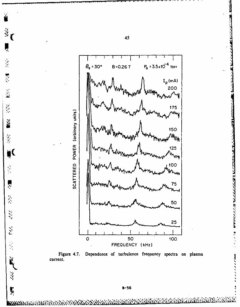
Figure 4.7. Dependence of turbulence frequency spectra on plasmacurrent.
a5
5-5
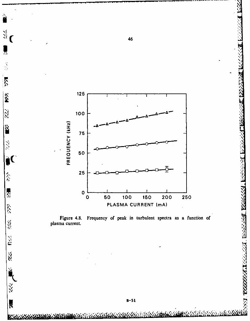
( 46
125
75
w t C
( a 50
U-
25 0
00 50 100 150 200 250
PLASMA CURRENT (mA)
Figure 4.8. Frequency of peak in turbulent spectra as a function of
plasma current.
'4-.p.oI
i

I ..
49
Os= 40 °
B = 0.26T
Ip 100 mA
-~ Po WO1 torr) VA Mk)
4 -
6.0 1.60
05. 50IO0
0
.-
0 B-52
-- 5

I oJ
125
100.
75
25
'p ~0 I0 0.4 0.8 1.2 1.6 2.0
ANODE VOLTAGE (kV)
Figure 4.11. Dependence on peak frequency in turbulent spectrum as afunction of anode voltage.
B-53

ir7i
4L
N -7
38
= ME
. 0
w
B-5

V
54
NNEL ICHANNEL 2
UUa.a- (L
LaJ -e
~.1o
00
> . , CHANNELt, M- I. - HNNLO
CHANEL ,, 2.
(wL
ZLw 0.50
c10.25
~ omw -,d
.,10 00 20 40 60 so 400 0 20 40 60 80 400
WAVE FREQUENCY (kHz) WAVE FREQUENCY (kHz)
Figure 4.14. Correlation of capacitive probes at the same anode location.
B = 0.26 T, P. 3.5 X 10⁻⁴torr, I = 100 mA.
B-56
4.. . . 4 . .

55
Cu% >J
CHANNELI > CHANNEL 2~~f-3
0.
W -4
w~~ 1(0
0 160 -
N 10~ I tooI-
3CHANNELS 1,2 U. CHANNELS 4, 2I... a0- a75
W -440 a: 0.50
D; W
m 1C5 n00.25
0 20 40 60 80 400 0 20 40 60 80 400WAVE FREQUENCY (kHz) WAVE FREQUENCY (kHz)
Figure 4.15. Correlation of capacitive probes at anode and cathode loca-tions. Channel 1 is the probe at the anode, and channel 2 is the probe at thecathode. B =0.26 T, P0 3.5 X 10⁻⁴ torr, I1, 100 mA.7
B-57

Abstract Submitted
For the Twenty-Sixth Annual Meeting
Division of Plasma PhysicsOctober 29 to November 2, 1984
Category Number and Subject 1.11 Electron Beam/Plasma Interactions
" Theory . j Experiment
Anomalous Drift Waves Detected with MicrowaveScattering in an Electric Field Dominated Plasma.*LARRY R. BAYLOR, J. REECE ROTH, PEYMAN DEHKORDI ANDMOUNIR LAROUSSI, Department of Electrical Engineering,University of Tennessee, Knoxville, TN 37996-2100.-We
-have operated a steady-state classical Penning dis-,charge in a uniform axial magnetic field of 0.4 Tesla.The electron number density is typically 2 x 10
9/cm3
n helium gas, with Te - 5-10 eV. We have applied 32
1Hz microwave scattering and capacitive probes it !.onjunction with a two-channel analog-to-digital dataandling system which is capable of producing auto andross power, phase, and coherence spectra. A strongackground of electrostatic turbulence was observed,he RMS values of density of which were as high aseveral percent of the average electron density. Thefluctuation spectrum exhibited several peaks between0 and 50 kHz, which appeared to be the fundamental
• - nd sub-multiples of E/B drift waves, characteristic6f Penning discharges (1). The frequency of this
"isturbance was proportional to B, implying a radialelectric field, the magnitude of which is proportional
":', io B 2 .
1. J. R. Roth, P. D. Spence, L. R. Baylor, D.. Rosenberg, and P. Dehkordi, Paper P1-12, 1984 Int.
Conf. on Plasma Physics, Lausanne, Switzerland, June284u4 orted by..contrac.AF.SJL1:0093..
B-58

IJJ
00
= z D 0~
~~> 0Li
I-i COO
%Awz0L U +o-Z f%
> -110 .-
cCW 06~,W-I
LL., 0 C)I 0I-LJ A L Z C.0
0> LL.> 0 r
<0. 0~-L
Q -ac
z mIA
B-5Z9 7
LI.
LU
ICIL4J
u3 0z
B-6

ION.
GAG
F AG, LEAN
PEA.
RI*U1411G 80ARGON
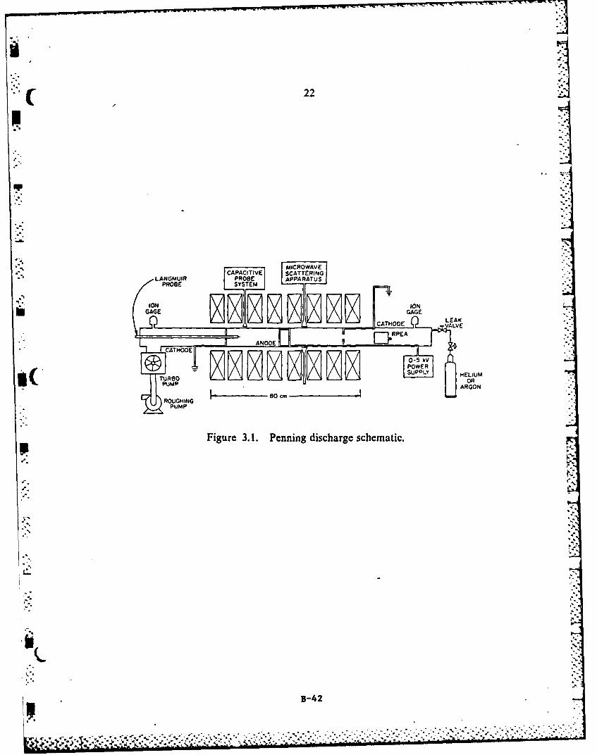
- Figure 3. 1. Penning discharge schematic,
B-61

L
iolo
0.2-r. -- ANODE'
J LOCATIONI 1 LOCATI ON CATHODEF -
~~LO CAT IO0N
.. z
0-80 -60 -40 -20 0 20 40 60 80
AXIAL DISTAN4CE (cm)
Figure 3.3. Axial magnetic field of UT classical Penning discharge.
I"
3-62
% - o-•,. *°." '.

--..---.- ~......-- --
La A- -e -I
I- I
-A ~
.7
*
i'-. YI---.
4X~-~-4~ ~ -
- - ~ ~
Ia - .~-'4'."- .~' -~ 7 -~~g/A-~---
-. - .:-~- -~ ----. N
-S %.-.
* '- ~; 7~'~
I ~/ :~~- j':
-S
iu~j~%-, .* .~%. - ~ L
B-63
- - - --

o a rEE1 :Z-;UJO
PH4SEPLASMA SH I F T -R
TEKT'RONIXALANCED TYPE O0 AMPLIFIER
VACUUM D ETECTOSH-05
RECORDER HIANDLING
SIOMATION SYSTEM
Figure 3.6. Microwave scattering experimental setup. AAYI
IIN
B-64

p- 4S v
tc
1 s-65

Laa
m"I
77, :1
Ii B-66

Po :3.5 x 0 4 torr
r 100 mA
Te = 5.2 eV 8T
.r.- Re O0.24xiO~ cm 3 0.40
0.3
0 .2
(L
0.23
-U)
0 50 100FREQUENCY (kHz)
* Figure 4.4. Comparison of turbulence frequency spectra on magneticfield strength.
B-67

100 "
80-:80 'C
SLOPE =226 x 10 3
60
ztu
o 40ul
20
48 x 10 3
oI I I p.
0 0.1 0.2 0.3 0.4 0.5
MAGNETIC FIELD (T)
Figure 4.5. Frequency spectra of turbulen:e vs mrgnetic field strength.
*.o11
5.
N
B-68

.0.2
0-
"= . 0.1.
hJ Z
10
0i: w
-o U 2
k-
00
9.0
8.8
' ,, < 8.8-a
8.2
0 0.1 0.2 0.3 0.4 0.5
. ,"" MAGNETIC FIELO MT
Figure 4.6. Plasma parameters is a function of" magnetic field strength.
"" B-69
- A
its.
.00
C
C-'
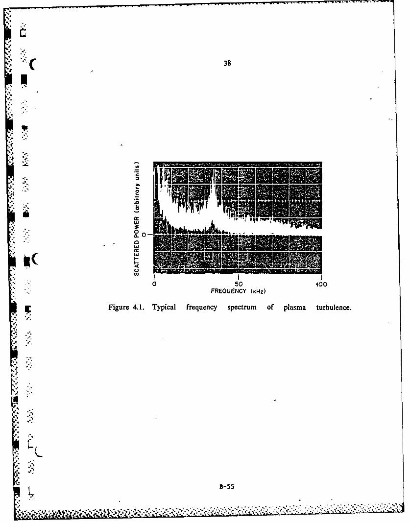
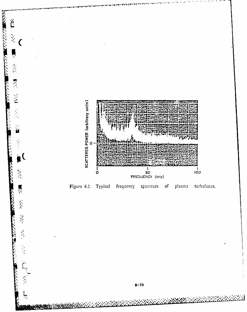
050 400FREQUENCY (kHz)
Figurt 4.1. Typical freq,-tncy s c cru m of plasma tu.-bjl-nce.
* B-70
Jil -Vt

'C
10
I I ~CHANNELS t4z 10
l [- CHANNEL .
r V)CLL Q7
w Z
-ai
.0
0 o0 4 0 so too a40
-4
,, L-, 0.5 '
Z.0 o 40 60 80 400 0 20 0 60 8o 0 400••WAVE FREOUENCY (kHz) WAVE FREC UE'NCY (kHz) %
;.- Figure 4.14. Correlation of capacitive probes at the same anode location.
B -0.26 T, P0 - 3.5 X 10- 4 torr, I - 100 mA.
B-71

."-
CHANNEL t 3CHNE 2.
2 10
t- c
ww W
iids
t'P C-) 100
2I 0Z ... I = 1 0"2 I
CHANNELS. 2 . CHANNELS f. 2
4. .,
0 ~ l
I:: ,6"KU
00 20 40 6 so Q 0 20 40 60 eo 100
WAVE FPEC:-'EN--CY (kHz) W/AVE FR--C U E'C Y (kh-)
Figure 4.15, Correlation of cap-citive probes at anode and cathode loca-tions. Channel I is the probe at the anode, and channel 2 is the probe at the
X. 10- 0 A
cathode. B 0.26 T, P = 3.5 torr,
I-.-
B-72

Lo 0)
4N -3
o 3
00 0E000 ol- o
o- -.w-- 8 I .s32S3Vc
W
C L i..........
cLLJ
7Z.7
a-f O. 0 L 01103 1 1 00 1 SO 0 0 sz *0 oo
Z..A -(L) wn~Il33dS-83M~id oirn' aZ 'i W1813d (')WLON33HO C3Svn
0) 40 o
0 o cm0U, 0 C AI C
5 T 0 4. i W.% C -I
N cow LdQ _jm a.x C0 oj to o In r- I
B-3w P.a
CL) C0 L
0 X CLiJ 44 -0 w o
dc 0cao, X 4. z VCV'0

01~
a
a- - ----4--
4L C
------- I I
* w
____ F.C0
a-
1CC
C
* ~~~ U. 0? . . ~ II , L . .~ o 8 li ~ 0 O -
C!C-0C000_ 0c l l' so:C 00,CzeeA -(t wnu 33d -83M cJ iny281) A81 3dS 3N3 ---,AD3 U M :a A
BV'w I
to 04 4m w0 1?C , a~
0~ 0 C3J w~ CC (iA )Op c "W - Sh ft *C w.1
OL C- ;21 It sC~b ~ 3~34 ~ zyw *r.bw w wx a

'II WON
Li ) U)
0 - -0
0 O.
0a -0
1.0L - -0001P oz 0 0 lz 07
am- Ne ni3SNMdon znw~3d S~
Ic ar7 0 LL
0 U.
?'.A ~ ~~C (C2 WA.34 v~idO
V) cua f
00 Z00- w :p
a 00 0
&0 w N .aa -. z w C z W.C.2 .4 ) L=~~ ~ ~ ~ 46 - Lj A L CccU ) CL zWF

0 0
o o
0 - , C.
aP C3
m-r
owLL 0 La-
00C; ua Lla
ow* (z) 0n13l N3ILOVav8 o w m l S
to
o 0
ou0
400
00 E
jgu. __ 0
tv -0 0M0
mn m4 w 4-
2 ~ - 43 U0Ml . a. w.
g0 N Wc
0. 4 0 -Cud
in g - a..-O r
000 z -, .La%COW au.JJ eZs-76
'U ! t,*.
-l 1 .a-I J

9
to 0
i C
00 L J.7I R--k
t- t0 I0,
OL.
LW
97 --l
,.0 -06. l . 00 1 00 1' 00 0 0 0 00 .00,()WAL33dS-N3MJd On 8 W(dl)n3dS 3H3Sa~Voos
0 la
I E
C?- *o? , -
>~ 4) ::: -. c
N P.- CD u
w C,)rix cck- 01
Z.- x W-C 0 4. 0. ". -C U
5-77

cm
c0c
10I!
AN, C!
o C
0
NOY
0 C3C.) t.
C- C3
0 or
10,
iCl
F-v
C20
S10 CIO3-78 :O A IjO

Ci ....',
Nq
. .4.. ,.
C ,). .
4,
7-7

RF SPECTRUM AS MEASURED BY APLANAR SPIRAL ANTENNA
C C:""'
K
. C.
500 MHz 500 MHz
40 PV/div 80 pV/div100 MHz/div 100 MHz/div
B = 0.385 T B = 0.3 TRUN#AOM1 RUN#AON1
, 1~
500 MHz 500 MHz
80 i V/div 40 MHz/div100 MHz/div 100 MHz/divB = 0.262 T B= .262 T
RUN#AO1 -80 RUN#AOQ5
-- ..... .

Abstract SubmittedFor the Twenty-Sixth Annual Meeting
Division of Plasma PhysicsOctober 29 to November 2, 1984
-W-lO Growing Waves and Electromagnetic Emissionfrom Two Oppositely Directed Electron Beams in a ColdBackground Plasma.* --J. REECE ROTH AND IGOR ALEXEFF,
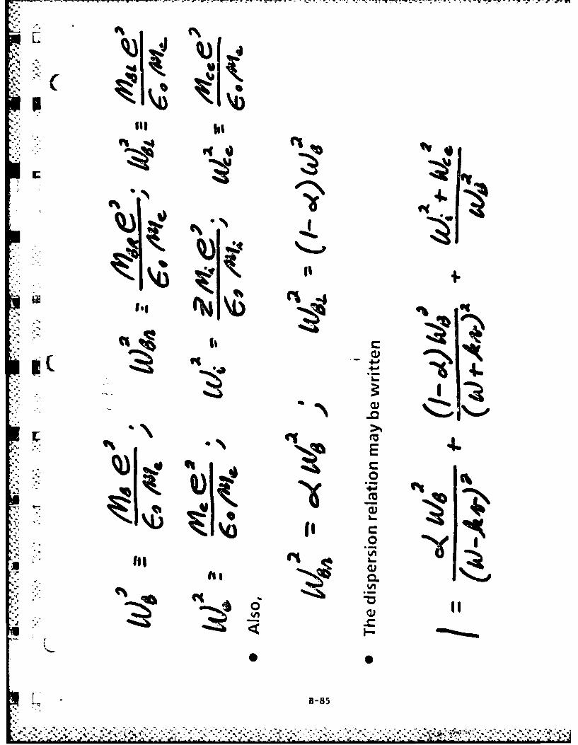
--University of Tennesee, Knoxville, TN 37996-2100.--Wepresent a generalization of previous theoretical work(1) to the case of two non-relativistic, oppositelydirected interpenetrating electron beams of unequaldensity interacting with a cold background plasma.These conditions can be reduced to a sixth-order coldplasma dispersion relation, which has growing anddamped solutions. In the case of two beams, each 1/2of the total electron density, interacting with coldions, we recover our previous result (1); growing
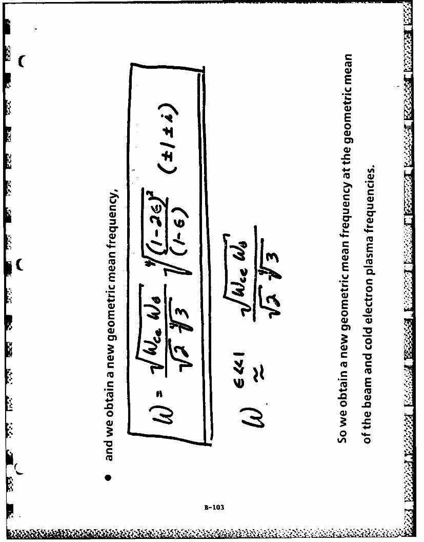
.' , waves near the geometric mean of the electron and ionplasma frequency. When the beams are much less densethan the cold electron background density, the growingwaves are near the electron plasma frequency of thecold electron population. The maximum growth ratesare not at the beam electron plasma frequency or atthe upper or lower hybrid frequency. The frequencyof an oscillator based on this instability can betuned by adjusting the relative intensity of the two
*beams as well as the beam density relative to thebackground plasma.
1.) I. Alexeff, J. R. Roth, J. D. Birdwell, and R.Mallavarpu, Physics of Fluids, 24 (1981) pp1348-57.*Supported in part b-A 0onEoacts 81-8093 and 82-045. and by ONR contract N00014-80-C-0063.
Paper IW-lO, Monday morning, October 29, 1984
Sheraton-Boston Hotel, Boston, Massachusetts
APS Bulletin, Vol. 29, No. 8, a 1198 (1984)B-8
L. B•-8 ""1", "'''' ";''"''' ::=a- . :. >>%.], i : :- :

az %AA- I
CO)
coz cn
4-D. -L (ZI LL~ 0 LLN c
Z Li tD u. CL ZLU W .Z c cWU om C)
QE4 '- c
YL 0 kZW 0 )CO
~~~ U- LiLu rLU CW 0- % 1
LU W LU (0 0 4-
LA .-i 1 - :3 C -4L ' 4 0
0 LL viN% 4- % V
Zi <l Lf < %A~ .I-J mi mm () mo :
wJC 0 L6
00-j0 %j.
o 0-~0 C-CO0.
C)0LL.>
B-82

z030
CLu- 0 3 .-uL -
.i 0
%nt ~ jA 3~7 S)0C
ott
~~40
Lo C o
LL0C a~ -- %
-~c 03
N- cc -0 M
wU 4-0 7_z
Q 0
L B-83

NO
II
B-84%mkmm --,
-Y. .-. e1E
L. (,%Ii
C,:h
L rw
- 4UN
II
C
B-85

. 4
4wA
0 40
-lot
B-4-0
m CL)
.2 4.~ ILl
I B -86

lII
-41+
IAI
ii
.4. +xI
(m~
,4 -IN
%Moo
IA.
0.7

I C,
I I,
I - 0
, 0*
0*-. ,.0
rr r r-----r----- 0/
-7 M-
IN1*
WC NOIOnfNIUdl
_ _ _ _ _B 88
I ii
-- -- ---
-- w
vi0
"I ol

UU
C'7
ICIS
a 0I~n 1 dSI
B-90c
1 , 0 LI I4
I 0
U,)
_ II 0
IA~ N0I.5) OIE3di
-~B-91

Qp61
t-I* q%4
-Z
U '

CC
4-0
a.%
IA
4-0I
4a4
V -s
.C
.,. ,' ' _..
4. .-0 ..tB-93
%C

IA!
94.
IAa
B9
.9 .o . •
-. I,.,.
f
4-9
1 %
1-94

fta
-A
d0
,.
ft..
B-954
IAI
oB-

..
::: ", I3"
I00
B-96

IV
lp
0
CL
0)
0-Mn0
IA x
W) C C
m+ 0
0) 4-0 WIN0.0
40CC . L
00
*9k.
-- .* *.B-97

LLC--
C I
C~aa
I--
* c0. c 0
.CLL
IA w
E _
CLII
'U, -Coi 4-0
U'B-98

LC4.l
.k4
II
U' CL
_ .C cn003 .~ c
4-0
B-99

AD-Ai68 425 ANNUAL PROGRESS REPORT ON CONTRACT AFOSR-81-8893 MARCH 3/315 1984 TO MARCH I (U) TENNESSEE UNIV KNOXVILLE PLASMASCIENCE LAB J R ROTH 3.8 APR 85 UTK-PSL-85-3
UNCLASSIFIED RFOSR-TR-85-8878 AFOSR-8i-0093 F.'G 28/9 N
EE~hhEmhEEEi|,I EihE..iEhillhEEIfllllllllllllllElaiEElhEiahiahE

L6
IIIJI5OL
Eper
1111.5 ltUr111 .
MIRCOYREOUTO ESHR T

p I
44
0
F&.
B-100
h U'
' °°t '
dl:

~cc
3-10

._0
."..
(,,.
, •
i'
ho
CrC
'"U
E E
04a)
it)
'kN
B,,,103
(,,,'a,
U C -lo
Ca 0

e~eI
B- 104
j .

0.48
0.40
0.32-
> 0.24 "'0 ,Z 0.16-w
• .. Lu 0.08- ,"' i,
LLCO 0001 REAL '
Cl)
aZ "0.08- "
z
-0.24- -.
-0.32 E= 00l: 0.50 ...
-0.40.*1..
-0.480.00 0.10 0.20 0.30 0.40 0.50 0.60 0.70 0.80 0.90 1.00 1.10 1.20
DIMENSIONLESS WAVENUMBER, x
10-105
S
. . .. . . . . . .- I.

1.00.
0.0 E=0
ai0
0.80
0.70-
.1.
i D ~ -
z, 0.60'
0 0.50-
LL
Cl) 0.40 -. __
Z 0.30-0
Lj 0.20-
0.00 0.10 0.20 0.30 0.4*0 0.50 0.60 0.70 0.80 0.90 1.00 1.10 1.20
DIMENSIONLESS WAVENUMBER, x
B-106J'

0.90,
6~80- f=0
0.70-
>~0.60'
Z 0.50-w0w 0.40,IL
C/) 0.30-wZ 0.20-0
w 0.10.
0.00-
-010
4. -0.
-0.300.00 0.10 0.20 0.30 0.40 0.50 0.60 0.70 0.80 0.90 1.00 1.10 1.20
DIMENSIONLESS WAVENUMBER, x
B- 107

I!S0.90 .
r0.80O : .10
~: : ~0.70-
" 0.60"
0
w 0.40-
- 0.30-
'C40
.1': ~-0.10o"-. 4(,
-0.20.
-0.30
0.00 0.10 0.20 0.30 0.40 0.50 0.60 0.70 0.80 0.90 1.00 1.i0 1.20
DIMENSIONLESS WAVENUMBER, x
, B- 108
e A

0.56.
6.48- E 10
0.40.- ~ .2
> ~ 0.32------- -
z 0.24. "k
w
w 0.6
U..
-)0.248.-
- 0.3200
-0.4
0.00 0.10 0.0 0.30 0.'40 0.50 0.60 0.70 0.8 0.9 1.00 1.012
DIMENSIONLESS WAVENUMBER, x
BK0

0.40'
0.32 -
.0.24-
C,,
Z 0.08-
0 ," REAL
0Z -o.18.6 "
z/ -o* ' , '',
zw -0.24-
-0.32 -
-0.40. 6=0-":0.75
-0.48.
-0.560.00 0.10 0.20 0.30 0.40 0.'50 0.'60 0.70 0.80 0.'90 1.60 1.10 1.20
DIMENSIONLESS WAVENUMBER, x
L(
.5".
B-110
.. . .- , ... . ... .. . ..• ... - -. . .: . .-..' - . -,:.. I " .'- , .".i ':. ' . , ,"i .' -:- -
-... . .. ;., , ,. -'%. ,-\,., , . . .- . .-. . " .-. ,. .-.,- . . .. , . .. -.. .. -*. * . . I .*I . , L, .., - I.

p 10 0.06 1>. 0.04-L
Z 0.02-- '
wD ~IMAGINARY
LL
C)-0.02-
Z-0.04-0
w -0.06- E=1/7348
-0.08-
* -0.10-
-0.12-j
-0.140.00 0.10 0.20 0.30 0.40 0.50 0.60 0.70o 0.80 0.90 1.00 1.10 1.20
DIMENSIONLESS WAVENUMBER, x

.0.90 E1/ 7348ayooi
0.80-
>- 0.70
Z 0.60wawi 0.50 --
CO 0.40CD)
-jZ 0.300CD)zLL 0.20
-----------0.00 -- -- -- ---- -- -- -- ---- --
-0.10 .
0.00 0. 10 0.'20 0.30 0.40 0.50 0.60 0.'70 0.80 0.90 1.00 1.10 1.20
DIMENSIONLESS WAVENUMBER, x

0.90 -
Q,80 e. 1/7348a=0.05
0.70
> 0.60
Z 0.50
W 0.40
,( co 0.30.to
Z 0.200
C. .'" ',
.. , - -'".J -0.10 ."'
- -0.20 -- ..-- - - ----
-0.300.00 0.10 0.20 0.30 0.40 0.50 0.60 0.70 0.80 0.90 1.00 1.10 1.20
DIMENSIONLESS WAVENUMBER, x
--. 1
,L41 '
,q l1-113

0.90 . '
0.80 :f 1/7348U=0.01
0.70
S,. > 0.60
Z 0.50.w
Uj0.40-
LL
U) 0.30
Z 0.200
z 0.10
0------------------------------------------0.00 .. . .. . . .. . ... . . 74:: :::: : : : : : --- -- -- -- -
7 -0.20 ".
., . . S:.
-0.300.00 0.10 0.20 0.30 0.40 0.50 0.'60 0.70 0.80 0.90 1.60 1.10 1.20
DIMENSIONLESS WAVENUMBER, x
I
1-114

0.56
0.48 E=1/7348
Cl= 0.25
t
0.32
.N-'
z O.402wS
a01 REAL f
0.4o.16
C) 0 .0 8 . . . . .
C,) "a.- ;
z 0.00 --, -- -0------------- ------------------------- ft f
z 0.08 %%
-0.24 ,,
0 .3 2 ... - - - -. ,
.3
1 ~-0.24"
-0.4 0 0.10 0.20 01.20 -
DIMENSIONLESS WAVENUMBER, x
5-115
N,.DM N IN E S W V N M E ,XT

0.48
-0.40 fz1/7348cl 0.50
0.32-
>' 0.24
z 0.16
a A
-/ 0.08 .
- 00 -- - - - - -
ilc% %
, j -0.16 -, ,
-0.24 -"
-0.32.
~~-0.40 -
0.00 0.10 o. o 0.k0 040 oao 0.60 0.70 0.80 0.90 1.00 1.10 1.20,
DIMENSIONLESS WAVENUMBER, X
B- 116 ;
RWIWI
LIE'L
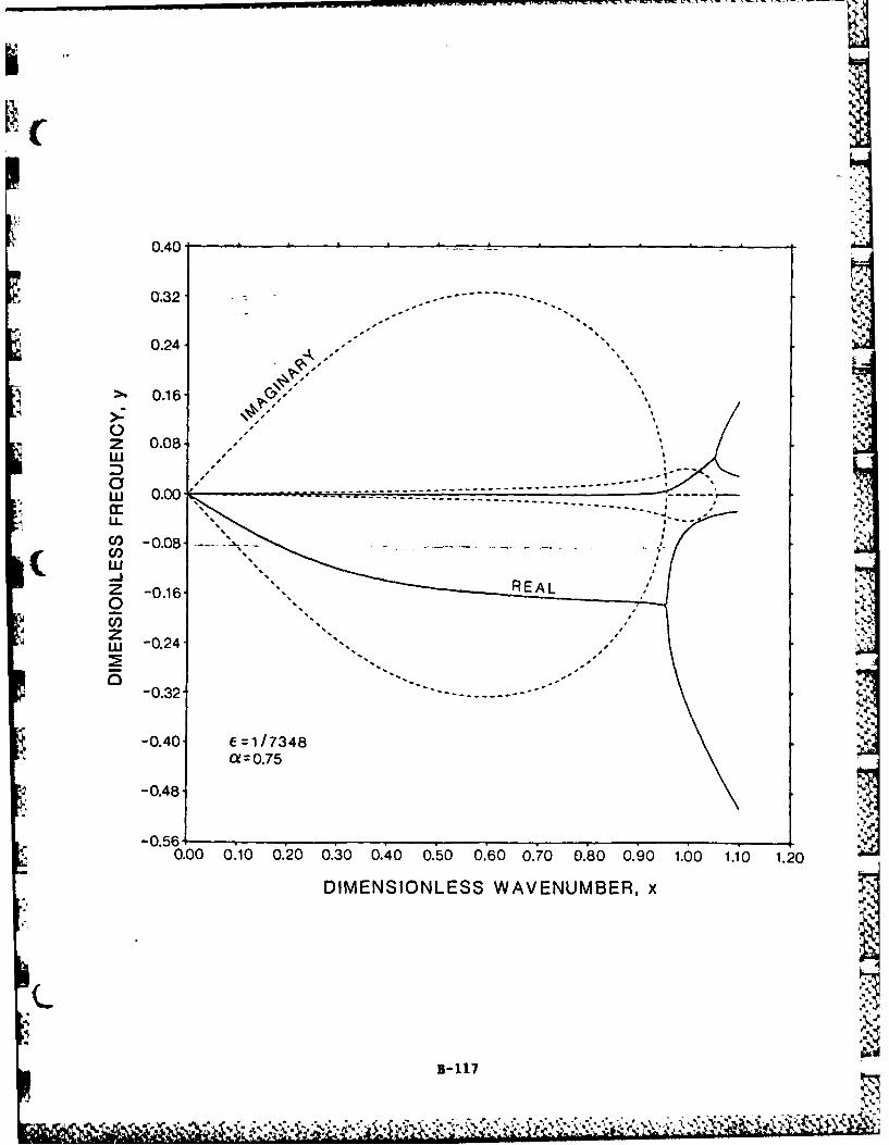
0.40
0.32 - - -
0.24-
" >, 0.16 ,,S'x S .
0 -6
u. ",.- -- --
0-0.
-0.03
z -0.40 ErIREAL
-0.48-
-0.560.00 0.10 0.20 0.30 0.40 0.60 0.70 0.80 0.90 1.00 1.10 1.20
DIMENSIONLESS WAVENUMBER, x
B-117
* ~ -.-6
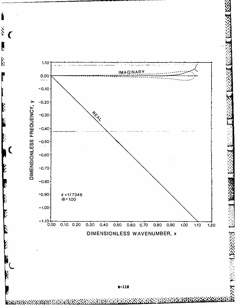
0.00.- - - - - -
-0.10-
4>% -0.20-
Z -0.30-w
wU -0.40.
C0,
Z -0.60-0U-5zw -0.70-
-0.80-
-0.90. f=1/7348
-1.00.
-1.1010.00 0.10 0.20 0.30 0.40 0.50 0.60 0.70 0.80 0.90 1.00 1.10 1.20
DIMENSIONLESS WAVENUMBER, x
B-118

'I!
6...
*i
i"?

CL
*0 0
m -0
0M
C
wE
B-12

W W
0 Ix t z -
IOI
-
vi w
c-IX<IC
I-40w
)U
IL
A ',kO~nO38:1SS3'lNI N3YC
3-121

x Ic'I00
0 w 0
IDx z
a. c.
XI--
- I II::al
3-a-0
wr- w
B2 2

p
a,
IA
SCL
.2
%WOO
(0x +M
EE
aa
a. mBa123

0 0*
4.'
.0 m C
Cu
4-0- 04-c +
0
%rnS C N
4+ ,.._A + E .
'Ac CuL.
I -- N 0
E• 2 -.
4-0 w .
,, B3-124.,
, , ,-.. . - , , .9,..- ,.o. ., . ,,-.,., ,,,: .., ,. ... . . ,.,.. .,,. ,.. .... ..... .. ,

po
I
l+ + +
0 C C
N 0 +CC
-- ._IIII
-. l. e44-'
44-0
4-0'
B-125

75 0
c m
CL;
4%.'
0'
'44
0
C *B- 126
0~ +l
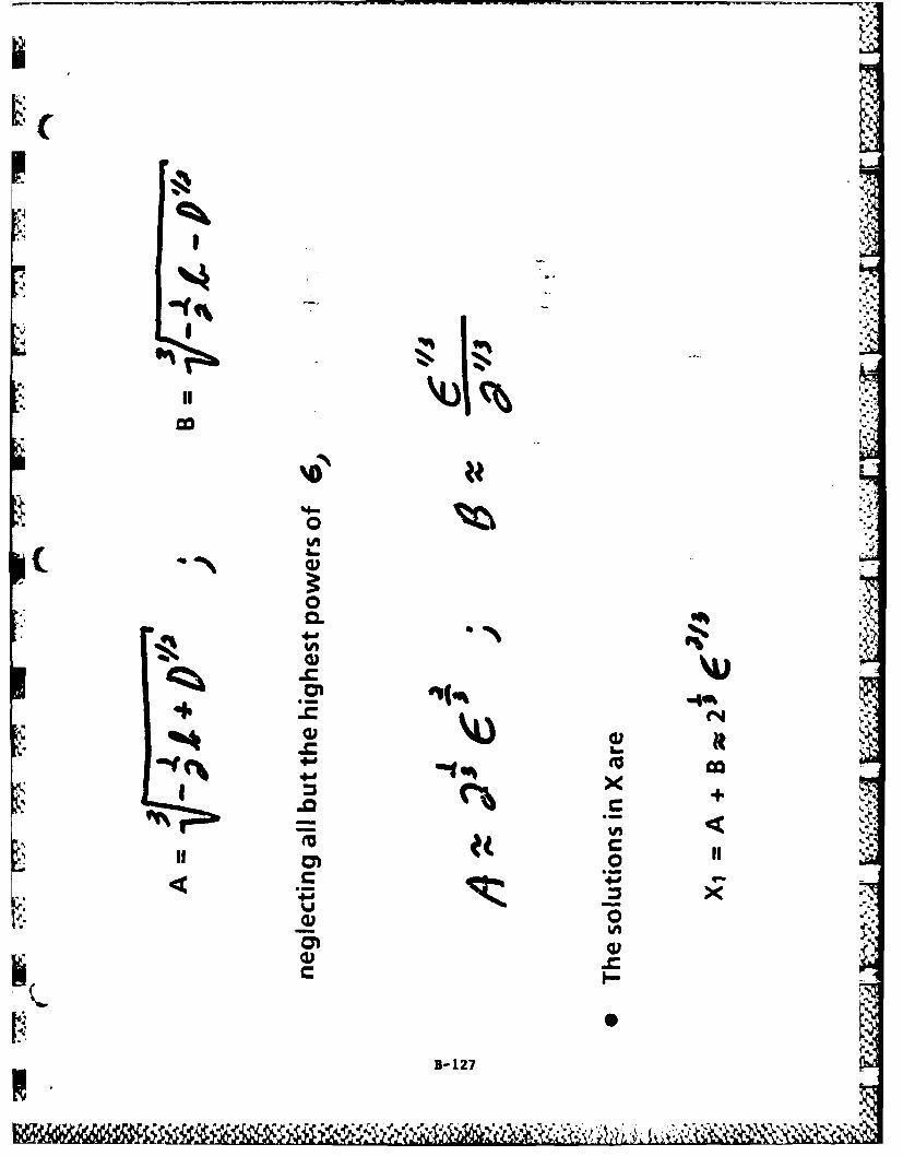
.
(
0 I- .E
" !!-B-17II

Cr
J
0
B1 28
, I,-
.- ,
U IA 'B-,

INI
0
4m
c'V
LMI l
B-129A~.

-, ---- 1.'
0.80
0.60'
0.40 ----
.0.209
z 0.00--,w
wl> 0.20"cc U-2
CD) -0.40
w0 -0.60
9- zw -0.80.
-1.00.
N -1.20' f =0.50aj=o
-1.40-
-1.600.00 0.23 0.45 0.68 0.90 1.12 1.35 1.57 1.80 2.02 2.25 2.47 2.70
DIMENSIONLESS WAVENUMBER, x
f
B-130
. . . ., ... , . . .4 . ,. . ,-,,,' . ,%o, -. . ,,,..%L, , -" : .,""

2.80-
'2.40
& 2.00.
>~1.60-
Z 1.20-
LL
C0,
z
-1.20. E 0.50Ci=0.25
-160
-2.004-0.0 0.3 0450.68 0.90 1.12 1.35 1.57 1.80 2.02 2.25 2.47 2.70
0.0 0.3 045DIMENSIONLESS WAVENUMBER, x
1-131

2.00-
1.60.
S1.20-
* LL
C,, 00 . - - -- - -
0
-1.20- E 0.50* h
Ci=U.50
-1.60-
-2.00.
-2.401.40.00 0:23 0.45 0.:68 0.§0 1.12 1.5 1.57 1.80 2.02 2.25 2.47 2.70
DIMENSIONLESS WAVENUMBER, x
1-132

2.40 ,.
2.00-
1.60.
., 1.20
o
0.80.
w
D$
0 .40,
w,--0.0 o.K .5 o6 .0 ; .s i .3 .2 2 2 7 27
-2) .00.
.0 .
LU 0.000. 23 04 .8 09 .2 13 .7 18 .2 22 .7 27
li DIMENSIONLESS WAVENUMBER, x
-- 133,
.-. f . 50,

Abstract Submitted for the
1985 IEEE International Conference%on Plasma Science
RF Emission Power and Its Dependence onPlasma Parameters and Turbulence in Pittsburgh Hilton
A Classical Penning Discharge*June 3-5, 1985
Mounir Laroussi, Paul 0. Sp~ence, David Rosenberg,John C. Mannone and J. Reece Roth
UTK Plasma Science LaboratoryU Department of Electrical Engineering
Univprsity of Tennessee('bKnoxville, TN 37996-2100
We have operated a steady-state classical Penningdischarge in a uniform axial magnetic field, the valueof which can be varied up to 0.4 Tes a. The electronnumber density is typically 2 109/cmi in helium gaswith Te = - 10 eV. RF emission has been detected Subject category and number:with specially developej, road-band planar-spiral and 17-Plasma Waves andconical-spiral antennas ,l and its absolute integralpower has been measured and plotted against electron Instabilitiesnumber density and electron kinetic temperature, withthe magnetic field as a parameter. The electronnumber density and kinetic temperature have been meas- Peeroasssoured with a Langmulr probe inserted into the plasma.Prfroasein
The RF emission spectrum covers a broad-band fre-quency range between 100 MHz and 1000 MHz. This soec- repsreso
'S trurn is formed by numerous harmonics of fundamentalfrequencies. The correlation between the RF emission ONo preference.spectra and the resul1s lready obtained on the elec- *Please schedule next totrostatic turbulence -,)due to strong axial and acmnygppebypencelradial electric fields(") and on wave propagation in Submitted by - e~the plasma is also investigated.,/ ~ / Z1P. Secand J. R. Roth, paper 3R3, IFE
International Conference on Plasma Science, ".Reece RothSt Louis, Missouri, May 1994. University of Tennessee
2. M. Laroussi, L. R. glaylor, P. Dehkordi, and 3. R.CopnRoth.: "Anomalous Dri ft Waves Detected with M1icro- Ferris Hall 409wave Scattering in an Electrical Field DominatedadrsPlasma", Paper 1 4-4. APS Bulletin, Vol . 29, 4o. 9 Knoxville, TN 37996p. 1197, (19q4). dslwn
(615)974-4446 .3. J. R. Roth, P. r). Spence, 1. R. Baylor,
n. Rosenberg, and P. Dehkordl.: "Correlation ofRF Emission, Plasma Wave Propagation, and PlasmaTurbulence in Classical and Modified Penning Important:Discharges', Paper P 1-12, Proceedings of the the Conference Record *01i be Produced by directInternational Conference on Plasmsa Physics, phoot~ion of sabmined abstracts. sothe duaity oatheLausanne, Swi tzerland, June, 1984. finaltextis thieresponsibilit ofeachminodiuaAthor the
Abstract must fit *-thin the bon on tire let and should be4. R. L. Pastel, and J. R. Roth.: "Axial Electric typed in a fce that is no smllerthlas 12 Pitch 112
"'S ~ets ad Eecton u'nbr dnsiy Pofies n aCharaclers pefrirChl A formrat simpleris ifiee inthe Call tarFiels ad Elctrn Nuberdensty rofies n a Papers announcemet
Clabsical Penning *)ischarqet, APS ;ulletin, Vol . 21 _
L %~o. R, pp. 1256-1257, (1993). ht.
*Slppported by AFOSR contract 91 -0093
B- 134Tis formr or a ressortable facsimile thereof) Plot three coples most be reCeOled NOT LAV(R THAN4 FEB 15 198S AT the tollvint addressor Martin 0 Niafteow caniereece Cra-rman Westrininose R&D Center 1310 8euiarr Road piorglt Pa 15"35
- ~ =k

Abstract Submitted for the
1985 IEEE International Conferencep on Plasma Science
Pittsburgh HiltonCollisional Magnetic Pumping Revisited*i
June 3-5, 1985J. Reece Roth and Mounir Laroussi
UTK Plasma Science LaboratoryDepartment of Electrical Engineering
University of TennesseeKnoxville, TN 37996-2100
Collisional magnetic pumping is achieved bywrapping an exciter coil around a cylindrical plasma, anddriving it with relatively low RF frequencies whichultimately transfer energy to the parallel component ofthe ion velocity. For this form of heating to take place,the period of the driving RF and the collision time should Subject category and number:be comparable, and both of these should be much lessthan the transit time of an ion through the heating 11 Plasma Heatingregion. Berger, et al. 1 have shown that if a sinusoidalperturbation of the confining magnetic field of the form B= Bo( 1 + 6 cos wt) is applied, the heating rate is given by
2' 02 Prefer oral session fNdE _ V_ (_)- E) Prefer poster sessiondt 6(9v2/4 + .- )
c CD No preference
where w is the driving frequency, vc is the collisionfrequency, 8 < < 1 is the field modulation2, and E is the( total ion energy. Transfer of energy to the parallel Subir.red b-component of the ion velocity occurs because themagnetic moment v,/8 is approximately constant. Thereis a small net collisional energy transfer to this parallel .7component as the magnetic field varies sinusoidally, and -j. Reece Pottthe perpendicular components of velocity follow suit. In a,,.e,,, enthis original form of collisional magnetic pumpingl, 2.3, Department of Electrical Enqr.the sinusoidal variation of v. 2 about the mean established coany,outside the heating region left only a very small net Iuniversity of Tennesseeenergy transfer, which is proportional to the square of the a-taessmall parameterS. Knoxville, TN 37996-2100
In this paper, we explore the consequences of Off stow, l
applying to the exciter coil a RF current wi h is either full (615) 974-4446wave rectified, B = 8o (1 + 81 cos jti), or which is a in
sinusoidal excitation with a DC bias magnetic fieldapplied only in the axial region ubtended by the excitercoil, B = go (1 + s + cosrt)). In both these cases, the Important:conservation of the magnetic moment will lead to anincrease in the perpendicular components of velocity the Conference Record will be produced by drne
above the equipartition values outside the exciter coil, but phoifeducton of Submitted abstrlcts so life Quai of themin eli $ Tihe ,reOl,nb,lin n Oft nmnldaif IO IU~lOn rllnot to a decrease. Thus any stochastic process, including ibslai t sti he responsiil b on the leil and huld bte
collisions in the heating region, is much more likely to iped in a flace Mtl is no smaller than 12 1dch 0iachieve a net energy transfer to the parallel velocity charactersper'nci AormatSampleisgvennntheCall forcomponent. This should lead to a heating rate linearly Papers announcenentproportional to the modulation 5, rather than to itssquare, as in Equation 1. If ions are scattered by %fluctuating electric fields originating from strong piasmaturbulence, this can lead to an effective collisionfrequency higher than the binary collisional value, and togreatly enhanced ion heating rates.1. 1. M. Berger, W A. Newcomb, J. M. Oawson, E. A,
Frieman, R. M. Kuisrud, and A. Lenard, Physics ofFluids, Vol. 1, No 4 (1958) pp. 301-307
2. K. Miyamoto, Plasma Physics for Nuclear Fusion, MIT(" Press, Cambridge, MA (1980) pp. 440-441.
3. T. Kammash, Fusion Reactor Physics, Ann Arbor ,. -Science Publishers, Ann Arbor, MI (1975) 161-182.
"Supported by the Air Force Office of Scientific Research,contract AFOSR 81-0093 (Roth).
B-135Thli form ion a leasonlye facsimie thereof) Plus thlree Copies MUST be received NOT LtER tHAN Ff 815 1911 S I a" ilO i fnm ln address
SMarin D iashemo Conierence Chirlman Vl lnlfolimntu O Cente, l I0 Beula Road P nsorig Pa 15, I"
.%.
I6

'4
k
APPENDIX C
.5
.5
* K*5
'a
4 *
* I.'...
*3 l.a..
'3.
'a..
/
as.

TRIP REPORT ON THE 1984 INTERNATIONAL CONFERENCEON PLASMA PHYSICS, LAUSANNE, SWITZERLAND
Dr. J. Reece RothDepartment of Electrical Engineering
University of TennesseeKnoxville, Tennessee 37996-2100
TABLE OF CONTENTS
Item Page
I. General Background 1
II. Invited and Review Papers 2
A) Wednesday, June 27, 1984 3B) Thursday, June 28, 1984 5C) Friday, June 29, 1984 8D) Saturday, June 30. 1984 11E) Monday, July 2, 1984 14F) Tuesday, July 3, 1984 16
It. Contributed Papers 17
IV. Laboratory Visits 19
A) Visit to Grenobel, France, June 25, 1984 20B) Visit to the Swiss Federal Institute of Technology,
July 2, 1984 23C) Visit to the Max-Planck Institute for Plasma
Physics, Garching, July 4, 1984 24D) Visit to the Culham Laboratory and JET Site,
,, July 6, 1984. 28
C-1

TRIP REPORT ON THE 1984 INTERNATIONAL CONFERENCEON PLASMA PHYSICS, LAUSANNE, SWITZERLAND
Dr. J. Reece RothDepartment of Electrical Engineering
University of TennesseeKnoxville, Tennessee 37996-2100
General Background
It was possible to set aside enough travel funds from contract AFOSR
81-0093 to cover my attendance at the 1984 International Conference onPlasma Physics which was held in Lausanne, Switzerland, from June 27 toJuly 3, 1984. The pecularities of the air fare structure made it possible to stay
overseas two weeks, from June 23, to July 7, $600 more cheaply than the airfare which I would have had to pay to attend the conference alone. I thereforestayed in Europe the entire two weeks, and used the extra time to visit threeadditional laboratories. These laboratories include the French Fusion
( Research Laboratory at Grenoble. France: the Institute for Plasma Physics at
Garching near Munich, West Germany; and the Culham Laboratory and theJET site, near Oxford, England.
In the report below, I summarize the invited papers at the conference.
reprints of which will not be available for approximately six months; I
describe a selected few of the poster papers which were of interest to me
personally, mostly relating to plasma turbulence, beam-plasma interactions,and radiation from plasmas. Other contributed papers are available in theproceedings, which was handed out at the conference. Finally, I included a
description of the site visits to laboratories which were part of the trip. jThis meeting in Lausanne, Switzerland was a joint conference of the
Sixth Kiev International Conference on Plasma Theory, and the SixthInternational Congress on Waves and Instabilities In Plasmas. This meetingrepresented the third time, at intervals of two years, on which these
individual conferences met jointly. Previous joint conferences in this serieswere held at Goteborg, Sweden. in 1982 (which I also attended and for which Iwrote up a trip report), and in Nagoya, Japan, in 1980. More than 450 papers
were presented at this conference by individuals from 39 countries. This
C-2

conference was sponsored by, among other organizations, the International
Union of Pure and Applied Physics. It was a well-unified conference. in which
the-e were no simultaneous sessions, with only invited review papers and
topical papers in morning and afternoon oral sessions. These oral sessions
were not held in conflict with the morning and afternoon poster sessions at
which all contributed papers were presented.
This joint International Conference on Plasma Physics is restricted to
- the theory and experimental aspects of high temperature plasmas. with low
temperature plasma phenomena being covered by the International
Conference on Phenomena in Ionized Gases, which is held on odd-numbered
years alternating with this conference. This conference was held in a major
conference hall which provided more than adequate facilities for the
conference sessions.
Invited and Review Papers
Unlike the contributed papers, there were no texts or even abstracts of
the invited papers at the meeting. The invited papers are to be published bythe conference organizers 6 to 9 months after the conference. The general
review talks were offered in the morning between the hours of 9:00 and 10:30:
each of two lecturers had about 45 minutes to present his topic. These were
intended to be broad topics of wide general interest. From 10:30 to 12:30 the
morning poster sessions were presented. After a break for lunch, the
afternoon poster sessions were presented from approximately 2:00 to 4:00 in
the afternoon. Starting at 4:00. there were sessions of invited papers on
special topics. On most days, there were two concurrent sessions of invitedspecial topic papers, and I report below on those which were of interest to me
personally. The morning review papers, and many of the afternoon invited
papers, were heavily biased toward fusion energy. The general content of the
papers at this meeting was similar to that of the American Physical Society's
Plasma Physics Division, except that some applications of high temperature
plasma physics, like astrophysical plasmas. received more attention than they
ever do at the APS Plasma Physics Division meeting.
2
K C-3

Wednesday, June 27, 1984
On Wednesday morning, Alan Gibson from Culham gave a survey of
recent results on ohmically heated plasmas in the JET facility, which is theworld's largest tokamak, and the centerpiece of the European fusion program.
The JET facility achieved its first plasma about one year ago, and has beenSoperating as an Ohmically heated tokamak since that time. The objectives of
the JET experiment have been broadened somewhat. By the completion of theproject in 1990, they expect either to have a reacting DT plasma which is
capable of burning in the steady state, or to show what must be done in orderto achieve a burning plasma in a larger machine. The JET facility has been
designed and built for remote maintenance, and so can burn deuterium andtritium for extended periods of time.
The primary issue in tokamak research at present is the scaling of the
particle containment time, since there appears to be no question that densities
and ion kinetic temperatures adequate for steady state fusion reactions can be
i ( achieved. The only open question is whether the individual ions can be
contained long enough on the average so that net power will be produced by aDT plasma. The question of confinement time scaling is a very vexing one,
since the physical process responsible for radial transport in tokamaks has not
been identified thus far, and the scaling of the containemnt time with plasmaP parameters has been estimated in terms of various phenomenological scaling
laws. The JET plasma is capable of operating with a circular or a D-shaped
cross section. It appears that the vertical elongation is no help in obtaininglonger containment times, based on experiments thus far with ohmic heating.
Starting in 1985, they plan to add neutral beam heating and ion cyclotronresonance heating to the JET facility. There are no plans at this time for
lower hybrid heating in JET. The parameters achieved thus far with ohmic
heating are electron kinetic temperatures Te approximately 2 keV, electronnumber densities of 2 x 10¹⁹ particles per cubic meter, and energy
containment times of about 0.35 seconds.A second general review talk was given on Wednsday morning by
Thomas H. Stix. who presented an historical survey of plasma waves, which
started with the observation of ionospheric whistlers in the military
telephones that were used in World War 1.
3
C-4,',:-:-.'-... ..

On Wednesday afternoon I attended the special topic session on MHD
phenomena in tokamaks. These papers were concerned with the MHD
activity which has been observed in tokamaks for some time, but only
adequately understood in recent years. In tokarnaks, the plasma acts as the
single turn secondary of a transformer and carriers a very large toroidal
current. This current not only heats the plasma by ohmic heating, but
provides a poloidal magnetic field which assists in confinement of the plasma.
Tokamak plasmas are unstable to a type of interchange instability in which
the current channel and the plasma undergo filamentation. When these
* ~kinstabilities occur in the core of the plasma. they act as a mixing mechanism,
and flatten the density and kinetic temperature profile of the plasma. When
they occur at the edge of the plasma, they can disrupt the equilibrium of the
plasma as a whole or, at a minimum, result in large bundles of the plasma
hitting the limiter or walls and being lost from confinement.
In the first of three papers, K. McGuire discussed observations of finite-
beta MHD phenomena in tokamaks. He was one of several tokamak
researchers at this conference to report a new form of MHD instability, "ERP",
a rather unfortunate acronym for "Edge Relaxation Phenomena", which
occurs at high beta, and results in rapid, cross-field loss of plasma
confinement. Various kink instabilities have been seen in high beta
tokamaks with azimuthal mode numbers as high as four or five. Whentokamaks are heated with such auxiliary heating methods as neutral beams,
additional MHD instabilities are observed, the effect of which is to reduce thenet efficiency of the neutral beam heating. In the Doublet-Ii tokamak and
PDX experiments in the United States, between 20 and 40% of the input
power is lost in the form of MHD instabilities which preferentially lose
energetic beam ions before they have an opportunity to slow down and heat
the plasma.P.K. Kaw of India presented a theoretical paper on resistive tearing and
ballooning modes in a high temperature plasma, which was addressed to
problems of MHD instabilities in tokamaks which arise as a result of a finite
electrical resistivity in the plasma. There has been renewed interest in thisLtheoretical area, since experimental observations of tokamak plasmas are
now pushing into a regime in which the older, infinite conductivity theory is
4%4
.C-4

no longer valid. Kaw's paper was particularly interesting because he usedquasi-thermodynamical arguments to reinforce and illustrate the practical
consequences of the theoretical results which he presented. He treatedtokamak plasmas as having a large free energy as a result of the ohmicheating current, and suggested that this free energy may drive such
undesirable phenomena as anomalous heat transport and resistive ballooning
modes.
Finally, L. Laurent of France discussed the nature of tokamakdisruptions, by which he meant the same phenomena which McGuire had
termed edge relaxation phenomena. He pointed out that they had observed onthe TFR tokamak extensive MHD activity at the edge of the plasma, whichmanifested itself by a rearrangement of the radial profile of plasma density
and kinetic temperature, as well as sudden plasma loss during the moreviolent disruptions. According to Laurent, there is no essential difference ,.
between major and minor disruptions, a distinction which had been putforward by some tokamak researchers earlier in the United States and Russia.but that he felt that tokamak disruptions or MHD instabilities differ only in
amplitude and mode numbers, without being significantly different in theirphysical origin.
Thursday, July 28, 1984
In the morning, there was a review paper by B. V. Chirkov of the USSRon the subject "Intrinsic Stochasticity" in which he discussed the way in whicha deterministic, Hamiltonian system in classical mechanics could take on orexhibit behavior which appeared to be chaotic or random in character. Theconfinement of charged particles in magnetic fields provides an example ofthis. As an exercise in classical mechanics, one can write the Hamiltonian for
the motion of a charged particle in a static magnetic confining field, andderive equations of motion which appear entirely deterministic. However, theactual particle trajectories are very often so complicated, that one finds itdifficult to make any general statement about in what volume of physical
space the particle will be confined, or even whether it will be confined or not.Chirkov defined a random process or phenomenon as one which wasunpredictable from observation and uncomputable, and in such a case one is
5C-6

generally reduced to using statistical methods to describe it. He distinguisheda random phenomenon from one exhibiting dynamical chaos, by which hemeant a random motion of a completely deterministic system without noise.
The second review paper of Thursday was delivered by Richard Post who
spoke on physics issues in mirrors and tandem mirror systems. He firstreviewed the current state of the tandem mirror experiment at the Lawrence
* - Livermore National Laboratory, and reviewed the physics of stability and
confinement in such devices. He pointed out that the tandem mirrorconfinement geometry differs from the tokamak in having a confinement timescaling that is well understood in terms of the basic physical processesresponsible, and is in good agreement with experimental observations.
hThe most interesting result which Post reported was that axial losses ofcharged particles from the tandem mirror geometry have now been reduced tosuch low levels that the major problem in the future for tandem mirrors willbe the radial transport losses. This is an important milestone in tandemmirror research, because they have now achieved such low levels of end losses
that they are in the same boat as the tokamaks and other toroidalconfinement geometries, where radial transport provides the dominantparticle loss. The major radial loss in the current tandem mirror is apparentlydrift losses, which arise in the end mirrors from azimuthal electric fields and
fluctuating electric fields.Post emphasized the importance of electrostatic potential control in the
confinement of the tandem mirror plasma. I have been working for many
years on electric field dominated plasmas, and on electrostatically assistedtoroidal confinement, and so I was very pleased to hear that at least one
national laboratory in the US recognized the potential importance of electric
fields to plasma containment.On Thursday afternoon there were several invited papers which I was
not able to hear because of scheduling conflicts between the two concurrentsessions. However, I did attend the paper by Strelkov of the USSR, whoreported recent results from the T- 10 tokamak in Russa. the largest tokamak
Lcurrently operating in the USSR. They have applied 1.2 megawatts ofmicrowave power at a wavelength of 3.6 millimeters and a duration of 0.1seconds for ECRH heating of the electron population in the T-10 tokamak.
6L. C- 7

They observed peak electron number densities up to 5 x 10¹³ particles per
cubic centimeter, and they have also observed an energy replacement time
which scales as the electron number density over the entire range of
operation. I next heard a paper by H. Soltwisch from West Germany, who
reported recent results from the Textor tokamak, a large tokamak which hasbeen built at Julich at West Germany with cooperative participation from the
United States. They have made careful measurements of the electrical
conductivities in the Textor tokamak, and find that the electrical conductivity
is somewhat below the Spitzer value.
I next attended a paper by W. C. Turner of the Lawrence Livermore
National Laboratory who reported some details from the TMX-Upgrade
thermal barrier tandem mirror experiment. In an attempt to understand theradial transport losses, they measured small potential fluctuations in the
-: TMX-U plasma of approximately 1 volt rms in the central cell. In the centralcell, the value of the plasma stability index beta has been as high as 30%.
Thus far, classical 900 scattering of ions on hot electrons seems to explain the
power balance. They hope ultimately to get to number densities of 2 x 10¹³
particles per cubic centimeter in the central cell of the TMX-U experiment;
now they have densities of about 2 x 10¹² particles per cubic centimeter.Finally, luean R. Jones of Australia discussed the rotomak concept as a
means of driving current in plasmas and creating spheromak plasmas. This is
" an approach which is the plasma analog of a squirrel-cage electric motor, in
.',. which a plasma in a long, uniform magnetic field is perturbed with a rotating,time-dependent magnetic field at right angles to the static, axial magnetic
field. The perturbing magnetic field is caused to rotate aziuthally about the
axis of symmetry of the magnetic field. This has the effect of inducing
currents in the cylindrical plasma column which flow around the axis of the
plasma and generate a spheromak configuration. which is roughly analogous
to a smoke ring in ordinary hydrodynamics. These rotating magnetic fieldscan be easily set up by a phased, series of windings outside the plasmaboundary, and represent a way of generating currents in plasmas which Iexpect to see widely imitated in the future.
t.
U7
uC-B. . . .

Friday, June 29, 1984
The first of two invited review papers was by 0. Gruber from West
Germany, who spoke on confinement regimes in ohmically and auxiliaryheated tokamaks. This paper documented the continuing attempt to find a
scaling law for the energy replacement time of tokamaks, in the absence of a
physical theory which predicts what this containment time should be.Tokamak plasmas that are heated entirely by ohmic dissipation have been
shown to follow the "neo-Alcator" scaling law,
which is consistent with data from a wide variety of tokamaks all over the
world. When additional heating mechanisms are applied, such as energetic
neutral beams, or ion cyclotron resonance heating, the neo-Alcator scaling t.
law no longer applies, and the containment time is generally less. Gruber
reported results from the Textor tokamak, in which they have observed
* "ELM's", which are edged-localized modes, a form of MHD instability which
they feel plays an important role in determining the energy confinement timeof tokamaks. When they use auxilary heating, the particle containment time
appears to scale as
=a~6 // 4, 5 (2)
where I is the toroidal current in megamperes, and Ai is the ion mass. The
size scaling is unknown at present, but the containment times calculated from
Equation 2 above are well below those for neo-Alcator scaling.The confinement picture at present is rather murky, but it appears that
the addition of auxiliary heating to tokamaks provides an additional source offree energy which gives rise to instabilities (edge localized modes) at the edge
of the plasma which carry large streamers of plasma away to the wall, and
reduce the effective containment below levels predicted by neo-Alcator
scaling. There is some hope in the situation however, since in a later paper,H. Furth pointed out that as experimenters become more familiar with the
(. operating regime of their device, they can adjust the confinement time. under
auxiliary heating, almost to the point which would have been predicted by
8
4 C-9

neo-Alcator scaling. It is very likely that scaling laws such as Equation 2 aremore a reflection of the amount of experience of a particular research groupwith auxiliary heating, then it is of any fundamental limitation on thecontainment time in tokamaks. Nonetheless, expressions like Equation 2
(sometimes called Mirnov scaling) have been used to scale presentexperimental results on auxiliary heated tokamaks to levels appropriate forengineering test reactors or even power plant reactors. It may very well bethat Mirnov scaling of Equation 2 is too pesimistic, and that the containmenttimes actually achieved in engineering test reactors and power plant reactorswill approach that of neo-Alcator scaling, given by equation 1.
The second invited review paper was by M. Kuperus of the Netherlands,
who spoke on solar physics. He concentrated on plasma-related phenomena,including particularly the dynamo model for the solar magnetic field, and the10.8 year solar sun spot cycle. He pointed out a fact of which I had not beenaware, that there is now geological evidence that the 10.8 year solar sun spot
(C cycle has been going on for millions of years. The physical process which
P 'maintains the solar sun spot cycle, and particularly which determines itsperiod, is not at all clear. He pointed out that most structures in the
photosphere and chromosphere of the sun (near its surface) are high betaplasmas, for which the plasma presure nkT, is nearly equal to the magnetic
pressure, B2/21,0 . The earth's magnetosphere is another example of a highbeta plasma. The phenomena in the corona of the sun, however, is low beta. Aparticularly interesting implication of Kuperus's talk was that muchconceptual and theoretical work remains to be done before the physicalprocesses which occur on the sun can be said to be well understood.
On Friday afternoon, I attended the special topics session on the rfheating of plasmas. A paper was presented by G. A. Collins of Switzerland,who reported their first results on Alfven wave heating of the TCA tokamak
at the Swiss Federal Institute of Technology in Lausanne. The TCA tokamakis a relatively small device with a major radius of 61 centimeters, and a minor
radius of 18 centimeters. It is the only major experiment outside the SovietUnion which is devoted to Alfven wave heating. Alfven waves propagate in amagnetized plasma along the magnetic field lines, and are analogous to thedisplacement which occurs when the string of a musical instrument is
9
C-lO

I plucked. The more dense the plasma, or the more massive the ions, the higher
the effective mass per unit length of the string, and the lower the frequency.The plasma-physical equivalent of plucking the plasma ions trapped on
magnetic field lines is excitation by an antenna at a few megaHertz or a few10's of megaHertz. These antennas were set up in the TCA tokamak, and theyare now capable of coupling a significant amount of power to the plasma(hundreds of kilowatts). The results are still very preliminary, but the TCAgroup has reported increasing both the electron and ion kinetic temperature
by 50% above the ohmically heated values with Alfven wave heating.We next heard from G. Melin of France, who reported on lower hybrid
heating in the Petula-B tokamak at Grenoble. This also is a relatively smalltokamak, with a major radius of 72 centimeters, and a plasma radius of 16.5
centimeters. They have operated this tokamak over a number density rangefrom 0.5 to 10 x 1013 particles per cubic centimeter. In their low density,lower hybrid current drive experiments, they also observed a limit on current
n ( drive effectiveness at a density limit of approximately 3 x 10¹³ particles percubic centimeter. At densities above this limit, lower hybrid rf power is in-effective at driving the ohmic heating current, but it is effective at heating theplasma. At electron densities above 6 x 10¹³ per cubic centimeter however,even the heating efficiency declines with increasing electron number density.
These limitations of lower hybrid heating and current drive are worrisome,since engineering test reactors and power plant reactors must operate atnumber densities somewhat above 1014 particles per cubic centimeter in orderto produce adequate power densities and a net power output. The Petula
discharge is subject to "kinetic disruptions" during the lower hybrid heating ofthe plasma. These look like the conventional internal mode disruptions of anohmically heated tokamak, but are triggered by the external energy input oflower hybrid heating.
R. Wilhelm of reported on the application of electron cyclotron heating(ECH) to the Wendelstein-7A stellarator at Garching. The Wendelstein-7A
stellarator has an L = 2 ( with an oval plasma crossection), a confiningmagnetic field of 1 tesla, a characteristic plasma radius of 9 centimeters, and a
( major radius of 2 meters. The heating efficiency approaches 50% for ECHheating of this plasma. It is possible to adjust the degree of shear and the
.. Z
10C-f11
-_ • c -i.l - ..* - '....'.'.' . . o . .. , . . . .. -, .. , .. ,.... -..... . :. - .- " . , . . -' '

rotational transform angle in this stellarator because it has a set of separatelyadjustable toroidal field coils and helical windings. They find thatconfinement is best when the magnetic field lines do not close on themselvesafter one or a few circuits around the major circumference of the torus; theserational drift surfaces lead to charge separation, the buildup of electric fields,
and enhanced plasma drift velocities.
Saturday, June 30, 1984Dr. N. Sato of Japan gave an invited review paper on the formation of
electrostatic potentials in a magnetized plasma. He described someexperimental work, done in his own laboratory, and reviewed the currentstatus of double layers, which have been a subject of active interest in
astrophysics and at the previous International Conference on Plasma Physicsat Goteborg, Sweden, two years ago. Double layers are steep potential profilesor strong electric fields which exist in flowing plasmas which are confined in
uniform or mirror-like containment geometries. This paper was of particularinterest, since we have observed strong axial electric fields in our modifiedPenning discharges, on the order of several hundred volts per centimeter. Inour case, these strong axial electric fields do not appear to be double layers,but originate from the high, anomalous electrical resistivity which is
characteristic of the highly turbulent discharges investigated in ourlaboratory. The subject of stationary double layers was explored in a
workshop following the Goteborg conference two years ago, and seems to bewell understood both theoretically and experimentally.
Sato pointed out that current interest in this area relates to moving orfluctuating double layers, which have been observed in several recentlaboratory experiments, including his own laboratory, and one at UCLA. forexample. Unlike the plasmas in our laboratory at UTK, the total potentialdrop across a double layer is usually a few times the electron kinetictemperature in electron volts, with electric fields from one to ten volts percentimeter. In Sato's experiment, he found what he interpreted as a
- fluctuating double layer, and that the electric field, voltage drop, and adecrease in the current flowing from one end of the plasma to the other wasassociated with the onset of current and potential fluctuations which were
C-12
-+* ** .'i -: I : - , , - . .-

strongest in the region of highest electric fields. These results sound very
much like the transition to turbulence observed in our own series of
experiments.
By having counterflowing plasmas originating from each end of a long
cylindrical magnetic field, Sato was able to do controlled experiments on the
behavior of double layers. An interesting such experiment consisted of
moving the position of a perturbing magnetic field coil along the axis of the
otherwise uniform, constant magnetic field, and by doing so Sato was able to
move the position of the double layer along the plasma. This agrees with some
of our observations at the UTK Plasma Lab, since we observe higher axial
electric fields in the modified Penning discharge, which is operated in a
magnetic mirror geometry, than in the classical Penning discharge, which has
a constant axial magnetic field.
Also on Saturday morning, we heard an invited review paper by D.
Pesme of France, who spoke on wave-particle interactions and plasma
turbulence theory. This also was a topic of personal interest to me because of
my long-standing interest in plasma turbulence. He presented a review of the
classic theory of plasma turbulence originated by DuPree and Kadomtsev,
which is based on normal mode analysis and resonant wave-particleinteractions. The quasi-linear theories have no mode coupling terms, which is
unrealistic in the face of a broad range of laboratory data which indicates
significant mode coupling. He discussed at great lengths the significance of
Gaussian versus non-Gaussian statistics for fluctuations in a plasma,
particularly fluctuations of the electric field.
In making plasma turbulence measurements in the past. I have often
seen Gaussian amplitude statistics for electrostatic potential (actually,
electric field) fluctuations, but it has also been possible to observe
experimental conditions for which the amplitude statistics of the fluctuations
departed substantially from Gaussian form. Experimentally, there appear to
be no great qualitative or even quantitative difference between the plasma
properties and transport coefficients associated with Gaussian versus non-
LGaussian statistics, so his contention that this was a significant physical
distinction did not appear to be very convincing to me personally. I
commented on this in the discussion period, and he replied that his comments
S-12
~~~~~~ .'. .. .- c . ..zr .. d

were restricted to two dimensional turbulence. I pointed out that the datawhich I had observed was in fact a three dimensional experiment. After thisexchange, several individuals in the audience came up to compliment me onhaving injected a note of reality into the discussion.
TIn the afternoon special topics session, J. Cary discussed some of theproblems of stellarator confinement. It appears that the principal difficultywith stellarator theory is that in the steady state, they do not have an axial,
ohmic heating current flowing in the plasma. and so there is no J x B bodyforce on the plasma arising from that source which allows one to convenientlystudy its equilibrium properties. From a theoretical point of view, stellaratorsare difficult to study also because of their lack of symmetry and the absence ofa rigorous plasma equilibrium theory. Cary described a relativistic electronbeam with a small angular spread, less than 10*-how much less he did not say-
and remarked that the same relativistic electron beam experiment dissipatedits energy in several meters, I assume in air. Kodian described the INARmagnetic mirror device at Novosibirsk, which is operated in a magnetic fieldof 2.5 tesla, with a maximum magnetic field of 4.2 tesla, and a length of 2.4meters. The plasma radius is 3 to 4 centimeters. The number density is veryhigh, and ranges from 1014 to 1016 particles per cubic centimeter. This is
apparently a cross-field device like the old "Burnout-5" device at the Oak
Ridge National Laboratory. Into this plasma, they apparently injected a 1MeV, 25 kiloamp relativistic electron beam, the pulse length of which was 50to 70 nanoseconds. The beam number densities ranged between 2 x 10¹¹ and 2x 10¹² particles per cubic centimeter. They found that after interacting with
the plasma, the beam loses energy, and increases its angular spread. Theyfound much microwave emission at number densities below 1014 particles per
cubic centimeter. Kodian reported a rather surprising result that themicrowave emission came out at twice the electron plasma frequency,whereas in our own beam plasma interaction experiments here at the UTKPlasma Science Laboratory, we find that most of the microwave emission is in
the vicinity of the electron plasma frequency itself.
13
0'. IA

."
. Monday July 1, 1984
One of the invited review papers on Monday morning was by Harold
Furth of Princeton, who spoke on the Princeton tokamak program. He spent
-'. most of his time reporting the most recent results of the TFTR ohmic heating
, ,experiments. So far they have had ohmic heating currents up to 1.5 megamps,
(about half the maximum achieved by the JET experiment) toroidal magnetic
p> fields up to 2.7 tesla, which compares with designed currents of up to three
megamps and 5.2 tesla. The TFTR has operated with one second of constant,
"flat-top" magnetic field. They have found that the loop voltage (the voltage
which drives the ohmic heating current) is still varying after 1 second. The 1
second duration is a limitation of the power supply: the fact that the loop
voltage is still changing after one second is an indication that they have not
established a steady state, and that the machine was designed with an
inadequate capacity to do so.
They routinely observe sawteeth and other forms of transient MHD
(phenomena in the TFTR, and have achieved electron kinetic temperatures of
|'1.5 to 2.0 keV with ohmic heating alone. They find that the energy
containment time under ohmically heated conditions follows the neo-Alcator-
* like scaling law
e(3)
where the geometric dependence is not clear, since all the tokamaks at
" Princeton have the same aspect ratio. The geometric dependence could be any
combination of powers of a and Rrwhere a +;r"= 3.
Furth described the conversion of the PDX poloidal divertor experiment
to the PBX, the Pringeton Bean Experiment, which is a verticaly elongated
tokamak plasma. the cros section of which has an indentation on the insidecircumference, which provides increased stability of the plasma. In his talk.Furth incorrectly attributed this bean-shaped tokamak configuration to
, -Mercier, rather than to William Bass and the topolotron group at Brigham
Young University in Provo, Utah. On theoretical grounds, stability of
i , tokamak plasmas with a bean-shaped cross section may be possible up to beta
values of 20%.
L 14C-15

f-(.
The second invited review paper of the day was by H. Wobig from the
Institute for Plasma Physics in Garching, who summarized recent work on
stellarators, torsatrons, and heliotrons. One of the interesting features of theWendelstein VI-A stellarator at Garching is that they have achieved very
high number densities, in excess of 1014 electrons per cubic centimeter, at the
same time that they have achieved ion kinetic temperatures, by neutral beam
heating, of 1 keV. In a similar device in Japan. the Heliotron-E, values of the
plasma stability index up to 3.7% have been observed.
Wobig listed the problems of the classical stellarator as being 1)
Impurities: Since no ohmic heating currents are required. in the steady state
impurities have the opportunity to build up to levels much higher than occur
in tokamak experiments which are pulsed and of a shorter duration. 2)
Stellarators have too low a value of the plasma stability index beta to be
practical for a reactor, 3) They have finite beta effects, which occur at values
of the plasma stability index of a few percent, that are detrimental to
S( confinement; 4) The confinement of stellarators appears to be consistent with
the neo-Alcator scaling of tokamaks, rather than neo-classical confinement;
and 5) The classical stellarator does not have a modular coil system and is too
complex to be disassembled by remote handling techniques. He described theWendelstein VII-AS, the suffix "AS" standing for advanced stellarator, which
is being built at Garching, and will go into operation in two years. This
advanced stellarator is being built with modular coils, and with a confining
magnetic field configuration which should allow higher values of beta than
the classical stellarator.
On Monday afternoon there were a series of papers on gyrotrons and
other cyclotron masers. A. Goldenberg of the USSR gave a survey paper on
gyrotron research in the USSR. He is from the city of Gorky, which
apparently is a center of gyrotron research. Much of his lecture was tutorialin nature, to provide background information for those of us in the audience
who were unfamiliar with the current state of gyrotron technology. He cited
the performance characteristics of some gyrotrons that apparently are under 2development in the USSR. He cited a particular test -yrotron intended tooperate at a wavelength of 3 millimeters and deliver 2 megawatts in 100
microsecond pulses. He mentioned that another gyrotron was being developed -7C-16 _
15 "

i for the T 10 fusion experiment to operate CW, at a level of 1 megawatt at 3.6
millimeters.
Goldenberg then proceeded to describe a rather intriging series of
experiments that were conducted at one atmosphere, in which the gas wasirradiated with microwaves at 8 millimeters at power levels that range from
below 1 kilowatt per square centimeter to values greater than 30 kilowatts
per square centimeter. Apparently the objective of this investigation was to
maintain a microwave-created fireball in a gas at 1 atmosphere, the purpose
of which was not specified.
G. L. Granatstein of the Naval Research Laboratory then gave a paperon Gyrotron and other cyclotron masers. their present capabilities and futureprospects. He pointed out that in the United States, a 1 megawatt cw-tube
was now under design, and otherwise described the current state-of-the-art in
the United States.
({ Tuesday, July 3,1984
John Dawson of UCLA gave one of the more interesting invited talks of
the conference, entitled "Collective Particle Accelerator". The device which
he described was a plasma-based method of accelerating charged particles to
TeV energies. This method is based on using an electron space-charge wave,
the phase velocity of which travels with very nearly the speed of light. Heproposes to trap positive particles, which it is desired to accelerate to high
*: energies, in a trough of such a space charge wave and then, as the wavepropagates at nearly the speed of light, the positive charge would be
accelerated up to very high energies, depending on how nearly it approaches
the speed of light. This plasma based method of particle acceleration has been
checked by numerical simulations done by Dawson and some of his colleagues
at UCLA and in the particle accelerator community. Dawson calculates thatintense electric fields as high as 109 volts per centimeter may be possible, and
this compares with about .2 MV per centimeter in the Stanford LinearAccelerator. Dawson calls this new concept the "surfatron", since the
acceleration mechanism is roughly analogous to that of a surfboard riding in a
Lf wave, with the wave propagating very close to the speed of light. The plasmaacceleration mechanism in this concept is over with too quickly for any
SC-1716
L ~~~~~~~~~. ....... .................................. ..........-,....- . -.. ,......-.,.--%.,.

instabilities to develop, and Dawson calculates that protons should be capable
of being accelerated to TeV energies in distances of a few tens of meters. This
is a very interesting idea, and will probably be worth a Nobel prize if it works,
since physicists have gone about as far as they can go with building ever-
bigger conventional particle accelerators.
The second invited review paper was by J. G. Lominadze of the USSR,who spoke on plasma instabilities in the magnetosphere of a pulsar. He
described the current "standard model" of pulsars. which is invoked to explain
the various phenomena observed in pulsar emissions. The standard model
contemplates pulsars which rotate rapidly enough, and have a high enough
internal electrical conductivity, that the magnetic field on their surface is
between 1012 and 1013 gauss. It seems that pulsars radiate about 1% to 0.1%of the total rotational energy which they lose. This rotational slowing can bemeasured in the lengthening of the pulsar period. A recent development in
pulsars was the observation of a pulsar outside our galaxy in the large{ ( Magellanic cloud, with a period of 0.9 seconds.
The standard pulsar model was put under a very serious strain recently
with the observation of a millisecond pulsar, a pulsar which supposedly isrotating so rapidly that it has a rotational period of 1.5578 milliseconds. This
represents a rather incredible object, and in the discussion after his paper I
asked Lominadze how short a period a pulsar would have to have before
astrophysicists would be willing to abandon the standard pulsar model. Hereplied that this millisecond pulsar was right at the limit, because if pulsars
having any shorter duration were observed, it would not be possible to explain
how they could hold together under the centrifugal forces acting their surface.
CONTRIBUTED PAIERS
L I found it very hard to document the contributed papers at the Lausanne
conference, beyond the four page abstracts which appeared in the contributed
conference proceedings distributed at the meeting. These four page papers
were published in two volumes, and are available in my office if further
information is desired about any one of them. The proceedings versions were
generally out of date, with respect to the poster materials actually presented
at the conference. However, almost none of the authors of poster papers.:,
I 17

I!
brought along copies of their poster materials or more extended reports for
distribution.My own paper entitled "Correlation of RF Emission, Plasma Wave i
Propagation, and Plasma Turbulence in Classical and Modified Penning
Discharges" was a comparison of the results in these areas from the Navy and
Air Force contracts which are being supported at the UTK Plasma Science
Laboratory. I reported not only our experimental results on RF emissions. but .
also described some of our diagnostic methods, including our recently-
developed broadband antennas which are calibrated in such a way that we can
make absolute measurements of radiated power from the plasma, over the
frequency range from 100 megaHertz to 1.2 gigaHertz. I was gratified by the L
interest shown in our work. There was a constant flux of people passing our
poster, and many interested questions on the detai is of the physics and on our
diagnostic techniques. We are using enough new, sophisticated, or unfamiliar
diagnostic techniques that many of our methods were new to many at the
conference. Our broadband antenna attracted particular interest, since, as far
as I know, no one else in the field is using such sophisticated antenna
technology to measure rf plasma emissions. One disappointment about my
own paper was that it was scheduled on the first session of the conference on
Wednesday morning, and the Russians did not arrive until late Wednesday
afternoon. I was thus deprived of the opportunity to interact with any
Russians interested in my work. In a concurrent poster session Wednesday
morning, there were several papers on low frequency waves and turbulence,
most of which represented rather small incremental advances over what has
been known in this area for some time. A particularly interesting plasma
turbulence paper was presented on Wednesday afternoon by E. J. Powers and
his students from the University of Texas in Austin. In a paper entitled
"Turbulence and Energy Cascading in the Edge Plasma of the Text Tokamak"
they made measurements of the fluctuation-induced transport rate inside, and
outside the limiter radius of this tokamak. They were able to show, at least in
the plasma boundary, that the fluctuation induced transport was of the proper
magnitude and sign to account for the radial transport losses in this tokamak.
They also carried forward the theory of turbulent fluctuations and used a
sophisticated statistical argument based on the bispectrum to identify the
C-19-
18
P WC

direction of energy cascading in the turbulent spectrum. In their case, theyhad a low frequency peak below 100 kiloHertz which seemed to be feeding
energy both to lower and higher frequencies. The nature of this energy input
peak frequency was not identified in these measurements, but it is clear that
this Texas group is getting very close to the fundamental physical processesresponsible for mode coupling and radial transport in tokamaks in general.
Compared to other and previous conferences, there were many fewer
papers on laser-related plasmas, and relativistic electron beams. There alsowere relatively few papers on astrophysical topics, which had been a dominant
.: theme in the preceeding conferences in this series.
There were contributed papers at this conference from both the EBT S
group at the Oak Ridge National Laboratory, and from the Nagoya BumpyTorus group, which was presented by its Principal Investigator. Ikegami. The
Nagoya group had some very exciting results to report from their bumpy
torus; recent application of a slow wave antenna allowed them to couple ICRH
f power into the Nagoya Bumpy torus plasma and achieve, on a pulsed basis.number densities up to 1013 per cubic centimeter, and ion kinetic
temperatures of several hundred electron volts. These results suggest that
cancellation of the EBT S experiment at Oak Ridge may be premature.
One of the dominant themes of this conference has been the increasing
*realization by both theorists and experimentalists of the role of electric fieldsand electrostatic potential wells in magnetized plasmas. In the past, the
description of most devices ignored plasma turbulence, or the effects of
. electrostatic turbulence; it was also assumed that radial transport and
confinement occured in the absence of any radial electric fields. This is nolonger the case. Theoretical models are now attempting to include radial
electric fields; and many experimentalists, particulary those with relativelymodest experiments in underdeveloped countries, are turning their attention
to plasma turbulence and its effects.
LABORATORY VISITS
Because of the savings possible on air fares by staying in Europe 2 weeksor longer, I was able to fit in three laboratory visits before and after the
conference, which lasted from Wednesday June 27, to Tuesday, July 3. 1 also
C-2019
F 'x;%.. :%*y: % .5; .."..°-;.? .. > ...;.**. . ..p.*.?*................. , -...'..........--'....-'.....,...........................,..........--....' .. ., "-. . ....r ,,V,, , -4= ", " - . . . ' # ' ' "

P was able to visit the tokamak laboratory at the Swiss Institute of Technology
in Lausanne, which visit took place on Monday July 2 during the conference.
Visit to Grenoble, France. June 25, 1984
The city of Grenoble is located in south-eastern France, about 70 miles
south of my air arrival point at Geneva. I traveled to Grenoble on Sunday,June 24, by train, to visit the high temperature plasma and fusion related
research activities situated at the French Atomic Energy Commission's
laboratory in that city. At present. Grenoble is one of two major centers of
high temperature plasma physics and fusion research in France; the other is
located at Fontenay-Aux-Roses, a suburb of Paris. The Grenoble laboratory
was set up approximately 15 years ago when the fusion research group then at
Saclay (another suburb of Paris) was moved to Grenoble.I found the French fusion effort, and those participating in it. in some
-'disarray. As part of a long-term plan for fusion energy in France, the French
government has decided to move all fusion research fromFontenay-Aux-Roses
and Grenoble to the southeastern city of Cadarache (Cad-a-rash), a small
village about 30 miles or so north of Marsailles on the Medetirranian coast.
The appeal of Cadarache apparently is that it is an economically depressed
area that the central government wishes to stimulate, and located there is amajor hydroelectric power facility, which is capable of meeting the power
demands of large-scale fusion experiments of the future. Apparently neither
Fontenay-Aux-Roses or Grenoble offer such capability. It is the intent of the
French government to develop Cadarache into a viable site either for the Next
European Torus (NET, the next step beyond the largest current tokamak
experiment in Europe ); or for the demonstration fusion reactor that is
envisioned as being the next step beyond NET.
r To make this move from the Paris suburbs and Grenoble (both of which
are very desirable sites from the perspective of the people now working there)to the remote village of Cadarache. the French government has committed
itself to build a very large superconducting tokamak experiment in
Cadarache, called Tor-Supra. This device is very impressive, approximately
the size and capability of the TFTR experiment at Princeton, but capable of
being operated in the steady state. The Tor-Supra is seen as a technology
C-21
,,20

development project, and the staff members with whom I spoke see very little
physics being accomplished in this device. It seems that the staff members of
the French fusion program are very unhappy about making this move to a
remote village, and many of them intend to go into other fields rather than
make the move.
While at Grenoble, I was able to inspect one of the sectors of Tor-Suprawhich had been sent to Grenoble for vacuum leak testing subsequent to their
manufacture. When these sectors past this test, they will be shipped to
Cadarache for assembly. The schedule of this activity is to shift the staff fromFontenay-Aux-Roses and Grenoble to Cadarache over the next two years. with
the transfer and setting up of the new laboratory to be complete two years
from now. At about that time, the Tor-Supra facility is to go into operation. It
is well along, judging from the hardware under test that I observed at
Grenoble. While at Grenoble, I spent some time with Dr. G. Melin, who is one
of the senior investigators on the Petula-B tokamak, the only large
experiment currently in operation at Grenoble. This small tokamak was
originally built in the mid 1970's to test transit time magnetic pumping as a
heating mechanism. This was abandoned several years ago in favor of lower
hybrid heating, to which the Petula experiment has been dedicated since
about 1980.At one time there was a second tokamak in operation at Grenoble, the
WEGA tokamak, which has been moved to another site. Probably because of
the small size of the Petula tokamak, the research group at Grenoble had
several years of difficulty with contamination and impurities in their plasma.
These problems have only recently been overcome by the use of low-Z
limiters, extensive discharge cleaning, and bakeout of the vacuum vessel. The
Petula-B experiment is well instrumented with diagnostic devices, which are
capable of measuring the amount of lower hybrid heating which actually
occurs. They have a pulsed klystron, which is capable of delivering more than
one megawatt for periods of a few tens of milliseconds. They have seen both
lower hybrid heating, and lower hybrid current drive in the Petula device, the
specific results of which were summarized in my discussion of Melin's invited
talk. contained in a previous section of this trip report. Like the experiments
at Princeton. and at MIT on the Alcator, they observed an upper density limit
C-2221
RW % 1.%

in the mid 1013 per cubic centimeter range, beyond which coupling of lowerhybrid power to thq plasma declines. In the Petula experiment, they also seethe same scaling law for the coupling of the lower hybrid power to the toroidal
current, when the lower hybrid power is used as a current drive. Their mostimportant contribution to lower hybrid heating technology has surely been
the development of phased waveguide arrays, in which the phase differencebetween adjacent waveguides are produced by baffles in the waveguidestructure, and not by phase differences introduced by modulating the
klystrons, or the geometric length of the waveguides. These baffle-like
structures inside the waveguide are capable of providing phased microwavepower, while being fed with a single klystron, a considerable advance over thecomplex waveguide arrays found in many other tokamak experiments.
Other activities at Grenoble include the vacuum testing of the Tor-SupraS"
: . "sectors before shipment and installation at Cadarache. These sectors are very
large and impressive, and are approximately the size of the sectors of theTFTR. These are the vacuum can which will surround the confinement
volume of the Tor-Supra tokamak, and do not include either the
superconducting coils, or the mechanical structure of the Tor-Supra facility.Also at Grenoble there is an effort on surface studies, in which an ion
source in a belljar bombards samples of candidate wall materials at normalinccidence and at 45' . Most of the samples studied thus far have been light
elements or low-Z materials; the individual with whom I spoke did not seem tobe aware of the fact that the sputtering yields and electron emission
coefficients of high Z materials like molybdenum and tungsten were muchlower than that of low-z materials. Apparently there is no activity at
.' '.." Grenoble on the Next European Torus.
The researchers at Grenoble apparently hope to apply their expertisewith lower hybrid heating and current drive on Tor-Supra, although the
present plans envision only enough lower hybrid power to supply 1/3 of the
current required on Tor-Supra. not enough to sustain the current by rf currentdrive alone. At present, it seems that there are no plans for lower hybrid
heating or current drive on JET; although several of the people that I talked toat Grenoble. at Garching and at Culham were a little shifty about this, since
the increasingly promising results of lower hybrid heating and current drive
C-23L. 22

. - ... .. • . -- r - | . .. . = - t . ..f .w .. .r- r - ,-s n , - : . -. :. -- - J: : - - -
Imake such an application increasingly attractive. There are a number of
recently assigned engineers busy at Grenoble on technology-related matters,
including the large radio transmitters for lower hybrid heating on Tor-Supra,
the cryogenic refrigerators and dewars, and other of the strictly engineering
aspects of Tor-Supra.When complete, the Tor-Supra will be the largest superconducting
tokamak in the world, and one of the largest tokamak experiments anywhere.It will, I believe, be comparable in size to the Russian T-15 tokamak. and
probably will go into service before the T-15 is on line. The French
government sees the Tor-Supra as not only a way of keeping the French fusion
effort credible on a European wide basis, but establishing the credibility of the
Cadarache site for future generations of fusion experiments. The role of theTor-Supra will probably be similar to that of the TFR tokamak. whichrepresented a previous attempt by the French governemt to put all of their
eggs in one basket in fusion energy. The TFR tokamak was for several yearsthe largest tokamak in the world, until the PLT came on line in the late
1970's.
Visit to the TCA Tokamak At Lausanne, Switzerland, Monday,
July 2, 1984.
As part of the conference, the local organizers arranged a tour of the
small TCA tokamak at the Swiss Federal Institute of Technology in Lausanne
on Monday during the conference. I took the afternoon tour, since few of the.poster papers in that session were of interest to me. The TCA tokamak is
supported ultimately by Euratom, and as such is a part of the coordinated•,. European fusion effort. This tokamak went into service about 1981, and for
several years was plagued with impurities and plasma-wall interaction
problems which kept it from meeting its potential in terms of electrontemperatures, confinement times, etc. It is a rather small tokamak, located inan experimental bay at the Swiss Federal Institute of Technology which ismuch too small for the experiment. Externally, at least, it is the cleanest
tokamak that I have seen. Everything in the laboratory was extremelyorderly, in its place, and it looked like the entire laboratory had been steamed
cleaned immediately prior to our visit.
C-2423

The TCA tokamak operates at toroidal magnetic fields of 1.5 Tesla,
ohmic heating currents of 180 kiloamperes, and it has achieved number
densities up to 5 x 10¹³ particles per cubic centimeter. The research topics to
which it is particularly devoted include Alfven wave heating, of which it is
almost the only large scale example outside the USSR; and collective
* Thomson scattering, a diagnostic development project which is attempting to
* - measure ion kinetic temperatures using Thomson scattering in the far
infrared. The Thomson scattering experiments are just beginning to produce
data, and in the few months before the conference, they saw signals which
they felt were definitely above the noise level, although not with signal to
noise ratios which allowed quantitative measurements of the ion
temperatures. Their worst problem with collective Thomson scattering was
the detection of very faint scattered signals at far infrared wavelengths.
where liquid helium cooled detectors are needed in order to measure the very
faint scattered signals. The Alfven wave heating experiments are moderately
( successful, with a rather high percentage (above 50%) of the power supplied to
the Alfven wave antennas actually being coupled to the plasma, and resulting
in measurable plasma heating. The exact, quantitative degree of heating will
be better known when the collective ion Thomson scattering experiment is
fully operational and capable of yielding the ion kinetic temperatures.
Visit to the Max-Planck Institute for Plasma Physics, Garching, WestGermany, on July 4,1984
Several of the individuals with whom I wished to visit at Garching,including Dr. Arnolf Schluter, and Dr. G. Greiger, were on vacation and notavailable. However, I spent the full day at Garching, and was able to see all of
the major experimental research projects now in operation.
Garching is the headquarters of the NET (Next European Torus) design
team, which is headed by Dr. R. Toschi, who until about 1 year ago was the
Director of the Italian fusion research laboratory at Frascati. The European
authorities set up a design team for the next European Torus in early 1983.
According to Dr. Toschi, this effort really got started in the summer of last
year. and the staff has now built up to a level of about 20 persons, and is
increasing rapidly in size at the present ime. The time schedule is long term, %
C- 25 -
24
' ifraed.The homon caterin exerientsarejus beinnig t prduc

in that by about 1988 they are to come up with recommendations as to the
objectives and general configuration of the NET device, but approval to spendthe r aey to build it will not be given until about 1991-92.
It seems that the general feeling in Europe is that the JET facility at
Culham is the largest physics device that it is sensible to build, and that the
NET must have, as an important part of its research program, the obtaining of
engineering test data and technology base information. Dr. Toschi apparently
feels that it is very important to begin the acquisition of technology relatedinformation, and that such a research program should start right now, or as
soon as possible. Dr. Toschi feels that it is going to be a difficult job not to go
too far beyond the physics data base of the JET experiment, while at the same
time designing a quasi-steady state burning plasma experiment that will be
sufficiently in advance of the JET facility to justify its very large cost of
construction.
He said they have a small group looking at compact tokamak reactors
and other similar alternates, but at present he does not see compact reactors.
even high-field, compact DT tokamak reactors, as a viable alternative to alarge DT tokamak. When I expressed suprise at this, considering hisbackground as director of the Frascatti lab, where a high field, compact
tokamak experiment has been one of their principal programs, he commented
that this experience of his was sufficent to convince him that compact reactor
concepts are not yet reliable enough and with the physics data base required
for the NET-generation of reactors. He intended to rely heavily on the
consensus information developed for the INTOR study, as a first
approximation to the NET design.
Dr. Toschi but several questions to me about the politics of the USFusion program, and the likely development of the US fusion program beyond
the TFTR. He was particularly interested in the role of the electric utilities in
fusion energy development, and commented that in Europe there was
virtually no electric utility involvement in the fusion program, even though in
most European countries fusion research and the electric utilities were both
basically government-supported enterprises. Dr. Toschi must have found ourLt conversation interesting, since it went an hour and a half beyond the
originally scheduled half hour duration.
C-2625

Also at Garching, I had an opportunity to talk with Dr. Aldo Nocentini,of the NET team, whose area of interest is the scaling of tokamaks. He wasinterested in some of my past scaling law studies, and I had a conversationwith him which confirmed my previous impression that the uncertainties in
scaling tokamaks from their present sizes to the scale of NET, or ademonstration reactor, are enormous, and the risks very great. Thecoefficients for the confinement time scaling of tokamaks with auxiliaryheating change on almost a monthly basis, and even the functionaldependence on the various machine and plasma parameters appear to change.The only reasonably constant factor in this shifting picture is the neo-Alcator
scaling law for confinement in ohmically heated tokamaks. This appears to bean upper limit for the other scaling laws, which have been observed when
auxiliary heating is brought into play.
I had a very interesting conversation with Dr. J. Nuehrenberg, who ishead of a theoretical section responsible for stellarator confinement theory.He and his staff at Garching are in contact with their ORNL opposite
numbers, who are involved with ATF (Advanced Toroidal Facility). All of theindividuals with whom I spoke at Garching in the stellarator area were very
familiar with developments at ORNL on the ATF. At least within WestGermany and the Institute for Plasma Physics at Garching, the stellarator isregarded as a backup to the mainline tokamak confinement concept, almost in
the same way that the tandem mirror is regarded in the United States. Dr.Nuehrenberg and his colleagues are well aware that the beta limit of classicalstellarators is far too low for a practical reactor, and also that the magneticfield winding configuration is too complicated from an engineering point ofview.
Dr. Nuehrenberg has been involved in the theory of the Wendelstein 7-
AS (Advanced Stellarator) which is now being built at Garching, and he hasalso examined the equilibrium, stability, and drift surface confinement notonly of the Wendelstein 7-AS, but other candidate stellarator like devicesincluding the heliac, modular torsatron, and similar devices, he remarked
that because fluctuation induced transport was likely to be a more importantradial loss mechanism in stellarators than in tokamaks, as a result of the
C-27
26
C.AC

F6
stellarator escape cone, which is nearly perpendicular to the magnetic field
lines in velocity space, and is not present in tokamaks.
I spent a very interesting three hours in the afternoon with Dr. H.
Wobig, a group leader of the Wendelstein 7-AS team. We discussed many
aspects of stellarator and torsatron physics, including their attempts to design
and build the next generation beyond the Wendelstein 7-AS, a much larger
device which would have enough clearance behind the confinement volume for
a relatively thick blanket. One of the problems with the Wendelstein 7-AS
design, is that the particle drift surfaces come relatively close to the vacuumwall (this was also a problem with the ATF design at Oak Ridge). but they
have formulated or discovered some more advanced magnetic winding
configurations which will allow enough clearance between the confinement
volume and the first wall or the coils for a blanket. Dr. Wobig escorted me to
an experimental bay where they have set up the first prototype models of theWendelstein 7-AS coils and vacuum system. I was astonished at the large
dimensions of the Wendelstein- 7 AS experiment. It will surely be the largest
stellerator-like experiment in the world, about the same dimensions, roughly,
as the Heliotron-E experiment at Kyoto, Japan. The vacuum vessel for theWendelstein-7 AS is certainly the most complicated piece of stainless steel
fabrication technology that I have ever seen. The cross section of the
confinement volume is roughly oval-shaped and this oval rotates around the
magnetic axis as one moves around the major circumference of the torus. In
order to compensate for this rotating oval, and allow diagnostic access
between the coil windings, the vacuum vessel (made out of eight millimeter
thick stainless steel) had to be formed into a very complicated shape. Dr.
Wobig worked with the Swiss fabrication company that made the sector which
he showed me. The manufacturer is now in the process of fabricating the rest
of the vacuum vessel. The coils required for the Wendelstein -7-AS are
probably the most complex geometrically of any normally-cooled copper coilsused in fusion experiments to date. According to Dr. Wobig, they had to have
a special development program to find flexible conductors that could be wound
into the complicated individual coil modules, without springing back when
the tension was released from the coil after winding. These problems have
C -28L 27
I:% Vw,",' , - " ". JW ' "k ' r ,, '"r , , v ,,m ' l .,~mIml( .. ' ,. .w m,,,M,,.

p°
l been overcome, and the complex modular coils required for the Wendelstein-7-
AS are now being fabricated. ,
- :i While I was there Dr. Wobig also showed me the Wendelstein -7-A.,.
"'" experiment which is a classical, I = 2 tokamak which is still operating at
Garching, and is scheduled to be shut down in 6 months to a year for the
assembly of the Wendelstein - 7-AS. The Wendelstein-7A experimental
results were described in an invited paper on this machine at the Lausanne
conference. These results have been very encouraging, having achieved, with
energetic neutral injection, values of the plasma stability index beta that are
those predicted theoretically (a few percent), while achieving number
densities up to 1014 particles per cubic centimeter. Another very large
experiment is at Garching is the ASDEX, or (Axi Symmetric Divertor
Experiment) which is a tokamak with a large divertor which can be operated
without any limiter in the immediate vicinity of the plasma. The absence of a
limiter or scrapeoff device apparently makes it possible to get impurity levels
on Asdex down to relatively low levels, while raising the electron temperature
at the edge of the plasma much higher than is possible with limiter-based
plasmas. The principal achievement of the Asdex experiment so far is that
when they operate with the divertor on, they can achieve a so called "H-mode"
of confinement, in which the scaling of confinement time approaches that of
the neo-Alcator scaling law.
I have the annual report of the Institute for Plasma Physics for 1983 in
my office. It is written in English, and is available to anyone who wishes more
information about the research program at Garching.
Visit to the Cuiham Laboratory JET Site, Friday, July 6, 1984
I made arrangements with Dr. John Butterworth of the fusion
" technology group at Culham to visit his group, the Cleo experiment at
Culham. and the JET site. I had a very interesting visit to the JET site,
during which Dr. John Maples escorted me around and showed me the very
impressive JET tokamak. When I visited this site two years ago, the JET
facility was just being assembled; one year ago it achieved its first plasma,
and is now in routine operation up to a total plasma current of three megamps.
They hope to apply neutral beam heating on JET for the first time sometime
C-2928
......... ..... ,..,. -.- .... -..-- .- "-'-..........................................................-..."...-.-..."...".."....:'

K..
in early 1985, and ICRH heating power sometime later in 1985. The JET
apparatus itself was not accessible to visitors when I was there, since it was
undergoing discharge cleaning. I did see the neutral beam test facility, which
is currently set up in the "hot cell"; the diagnostics hall; and the assembly
hall, where they were making ready some neutral beam injectors andadditional diagnostics for installation on JET. The recent experimental
results of the JET experiment were summarized in Allen Gibson's invited
talk which I described above. The scale of the JET facility is impressive and
the engineering of the entire facility and its auxiliary office and operational
buildings is absolutely first class, far more impressive than our own TFTR
experiment.They apparently have not changed their intention to burn deuterium
and tritium only after a very long series of preliminary trial experiments with
ordinary hydrogen: these DT experiments are not anticipated before about
1989, inspite of pressure on them from the TFTR experiment, which intends to
burn DT rather early in its operational history. I found the diagnostics hall
particularly impressive, since all of the diagnostic equipment is outside the
shielding wall which will be needed for DT operation. They are developing the
technologies needed for remote diagnosis of burning tokamak plasmas and
seem to be well ahead of us in this respect. Many of the RF-based diagnostics
were being set up and debugged when I was there It was evident that the
technology required for these diagnostic instruments have been fabricated by
companies and national laboratories from all over Europe.
I had some interesting talks with several members of the Cleo group,
about their recent series of comparisons in which they operated the Cleo
device as a tokamak: a stellarator: a helically-assisted tokamak: a reversed
field pinch (RFP); and as an OHTE (Ohmically Heated Toroidal Experiment).
The Cleo device is one of the few that was designed with toroidal magnetic
fields and helical windings sufficient for operating in these various
containment modes; by adjusting the machine parameters they are able to go
smoothly from one mode of operation to another, and to make comparative
studies of confinement lifetimes, number densities, beta limits. etc. in the
same machine and with the same diagnostics. They have found thus far for
example, that confinement has been best in stellarators, but the beta limits
C- 302 9. . . . ._.
2 ., '.* . . . . . . . . .

highest in their tokamak configuration. Because they have difficulty in
varying the number density as an independent parameter, they have not yet jbeen able to determine the scaling laws for confinement in configurationsother than the conventional tokamak; they hope to get scaling informationfrom the other configurations in the near future.
I gave a seminar at Culham on some of our work here at the UTK
Plasma Science Laboratory, which seemed to be well received, and resulted inseveral requests for reprints, in addition to distribution of all of the reprints -::4
that I had brought along. The fusion technology effort at Culham is a rathersmall one, involving only about 6 or 8 professionals: they do not seem to bewell integrated into either the experimental program at Culham, or into theNET or JET programs. I got the rather clear impression that the physicistsare still very much in charge of the European fusion program and, except for
Dr. Toschi of the NET team, the importance of engineering test data for thefuture of fusion energy does not seem to be widely appreciated there.
C-31
30

'Cp
N
APPENDIX 0
1~
~1

UNITED STATES AIR FORCEA.R FORCE OFFICE OF SCIENTIFIC RESEARCH
BUILDING 410. BOLLING AFB, 0. C. 20332
GRANT O. IEFFECTIVE DATE I PURCHASE REQUEST NO. PROJEC-TA K
AFOSR--O52 15 Feb 85 FQ8671-8S00298 2917/A6 - 34 GRANTEE AUTHORITYS l-Universty of TennesseeAMOT 10 U.S.C. 23S5I 404o Andy Holt Tower AMOUNT
Knoxville TN 37916 6233.74S
D~URAT ION (Wnihsl)
! 12
PRINCIPAL INVESTIGATORDr. 1. Reece RothADMINISTRATIVE OFFICE SPONSORING SCIENTIFIC OFFICE PAVING OFFICEAFOSR/PKZ AFOSR/NP Dot 1, 76 ALD/ACFMCCBuilding 410 Building 410 Bolling AFB DC 20332-S260Bolling AFB DC 20332-6448 Bolling AFB CC 20332-6448NEGOTIATOR (Name. OrBonizatiom Tele phone o) PROGRAM MANAGER (Name. Organiatlm Teiephone Noj.)
, 3ANE 0. DADE Dr. Robert 3. Barker. PKZ (202) 767-49Sl/3dd NP (202) 767-5011
RESEARCH TITLE"Investigation of RF Emissions from Two Beams Interacting with an
Electric Field Dominated Plasmam
ACCOUNTING AND APPROPRIATION DATA
57S 3600 29S 4781 612917 A6 00000 61102F S03700 F03700 AZ $233.74S
PAYMENT SCHEDULE
$233.745 on or after 15 February 1985TERMS AND CONDITIONS
THIS GRANT IS ISSUED UNDER THE DEPARTMENT OF DEFENSE (OOD) - UNIVERSITY RESEARCHINSTRUMENTATION PROGRAM (FY 1984/FY 1985) FOR THE PURPOSE OF UPGRADING THE
, - UNIVERSITY RESEARCH INSIRUMENTATION IN ORDER TO IMPROVE THE CAPABILITY OF* UNIVERSITIES TO PERFORM RESEARCH IN SUPPORT OF NATIONAL DEFENSE. SPECIFICALLY
IT IS A PROGRAM OF SUPPORT FOR THE ACQUISITION OF RESEARCH EQUIPMENT FOR THESTIMULATION AND SUPPORT Of BASIC RESEARCH UNDERLYING THE TECHNOLOGY GOALS OfDOD.The above funding is hereby granted by the Air Force Office of ScientificResearch (AFOSR) for the acquisition of equipment identified in the equipmentlist contained herein. No indirect costs are chargeable'to grant funds.
Pursuant to the provision entitled OCost Sharing" of the AFOSR Brochure entitled'Administration of U.S. Air Force Grants and Cooperative Agreements for BasicResearch, August 1983" the Grant amount is $233.74S and the Grantee cost sharing
* amount is $0 (The total project cost Is $233,745).
FOR THE GRANTEE FOR THE UNITf STATES OF AMERICA% SIGNATURE OF PIER N AT WORIZED TO SIGN SIGN URE OF CO OFCR
L NAME AND TITL.OF 5 NO MT(7 Print) DATE SIGNED NAME OF eNTRACTING OFFICER (Trpe or Pien) DATE SIGNEDL Er .c . _1 : H . F r y ..:: .....;. - , . 11 1% .: ... , .
~ E~EOI* H. LY ~--- -..- ~ 1 -i'85 HARRY R. HARAIMENSI AFC Pom 14 £rSC-Mdleow ATB DC i114
4w AFSC JU 4, 442 PReVIOUS 9I0TIONS ARE OIOLET.
D-1I
.~ ~ ~ ~ ~ ~ I .~i all, . , . . - .- .. ,.--,-,. ..,..- . ,.:.'. .,:'.'

Grant No. AFOSR-85-0152 Page 2 of 3 Pages
Grantee is authorized to acquire the following items of permanent equipmentlisted below. Title to items shall vest in the Grantee at the time of
* .... (Vacquisition and the Grantee agrees that no charge will be wade to theGovernment for any depreciation, amortization or use charge with respect tosuch items under any existing or future Government grant or contract.Variation from these items require the prior written permission of theContracting Officer. ..
Estimated Charge._--- --.--.-- Item-Description. To Grant Funds
Spectrum Analyzer Plug-In $ 10,920.Automatic.Preselector . - . . 5,980: r '. - avegutde -Harmonic MixerS t. . . . .. . .. ..... .. . .. . 3.100 . .Histogramming Data Memory 990
Programmable 3-Speed Clock 1,170Quad 10 Bit Transient Recorder 3,990Memory 8210 590Oscilliscope Camera 1.315
....... ass Spectrometer . .. .. 12,087Magnet System and Power Supplies 25000Network Analyzer, Low Frequency 31,158Controller and Accessories 19,653Experimentation Accessories 1,420Network Analyzer. High Frequency 86,598Sweeper 26 630
-, Shipping .. . . . . . 3,144At any time during the performance of the research period. Including at thecompletion of the research, the Grantee shall inform the Contracting Officerin writing of any grant funds in excess of the amount actually needed for theacquisition of the equipment specified in the grant. Disposition of suchexcess funds will be as determined by the Contracting Officer.
o.D
3.-.., . - , ., .. . • .. . , -. . , ' ' I"I.

Grant No. AFOSR-85-0152 Page 3 of 3 Pages
The following provisions of the AFOSR Brochure are incorporated by referenceand made a part of.this agreement:
-V. COST SHARINGAD3USTMENT "K. -EXPENDITURE LIMITATIONSSUSPENSION AND TERMINATIONCOST SHARING
. ,!.FINANCIAL STATUS REPORTSUNEXPENDED FUNDS AND EARNED INTEREST
IV MANAGEMENT SYSTEMS. ACCOUNTING RECORDS AND AUDITPROPERTY MANAGEMENTEQUAL EMPLOYMENT OPPORTUNITY
..,PROCUREMENT STANDARDS FOR SECONDARY AGREEMENTS
Cost,.provided-under this grant are exclusively for the acquisition of-equipment and not for any salary costs for research. Indirect costs and costsfor supplies.continuing operations and maintenance are not chargeable togrant funds. Other costs directly related to the acquisition of the equipmentmay be allowable as determined by the Contracting Officer.
Grantee will provide an interim status report 6 months from the award of theGrant and a final report sixty (60) days after completion of the Grant whichwill identify the equipment actually acquired (although it might vary withthat described in the Grant) by name, manufacturer where possible, and costdescribed any special circumstances regarding the acquisition or changes tothe equipment list. The final report will also include a concise summary ofthe research projects on which the equipment has been or will be used,including support of (a) the research work described in the proposal and (b)
4 other research work of interest to the DOD. The AFOSR Program Manager mayrequest up to two informal letter reports during the performance period whichdescribe the Grantee's progress in acquisition or fabrication and use of theresearch equipment.
D
D-3
- .VG ~

I *
Ip
A
r.
[PAPPENDIX E
Ir
it
B
- - ~- U -~ .~ .,.

i j
MICROWAVE SCATTERING AS A PLASMA DIAGNOSTIC
IN A PENNING DISCHARGE
A Thesis
Presented for the
Master of Science
Degree
The University of Tennessee, Knoxville
Larry R. Baylor
L June 1984
* E-1

ABSTRACT
A microwave scattering apparatus consisting of 32.175-GHz Gunn diode in
a conventional homodyne mixer configuation has been built to investigate
plasma turbulence in a steady-state classical Penning discharge. The
microwaves are incident on the plasma in the ordinary mode at a power level of
25 mW. The scattered microwave power is observed for scattering angles from
20 to 1600 in a plane normal to the magnetic field axis. The scattered
microwaves are fed to a balanced mixer where they are detected with crystaldetectors. The detected signal is then displayed on a spectrum analyzer or fed
into an analog-to-digital data handling system for analysis and correlation with
other signals.
S( In these experiments the electron number densities ranged from 108 to
1010 /cm 3, the magnetic field ranged from 0.1 to 0.4 T, the discharge current
ranged up to 0.2 A, and the input power ranged from 50 to 400 W. The fre-
quency spectrum, angular dependence, and scattering amplitudes were meas-
- - ured with the microwave scattering diagnostic. Data from the microwave
scattering diagnostic were correlated with plasma operating conditions and with
data from capacitive probes which measured electrostatic turbulence. The data
indicate strong, low-frequency electrostatic turbulence in the plasma, caused by
E X B drift.
.
,k.
.4.,

iv
TABLE OF CONTENTS
CHAPTER PAGE
INTRODUCTION............................................I
I. SCATTERING THEORY .................................. 2
Scattering of Electromagnetic Radiation ...................... 2
Scattering from a Plasma ................................ 7
Scattered Spectral Density ............................... 9
II. PLASMA TURBULENCE................................. 12
Plasma Theory ........................................ 12
Penning Discharge Plasma................................ 14
I11. EXPERIMENTAL METHODS AND PROCEDURES ........... 21
The Classical Penning Discharge .......................... 21
Microwave Scattering Diagnostic .......................... 25
Homodyne Detection................................. 25
Microwave System .................................. 30
Data Collection........................................ 35
IV. DATA ANALYSIS ....................................... 37
V. DISCUSSION OF DATA.................................. 56
VI. SUMMARY AND CONCLUSIONS ........................ 60
LIST OF REFERENCES....................................... 62
APPENDIXES ............................................... 66
APPENDIX A. LIST OF SYMBOLS ........................ 67
APPENDIX B. PLASMA PHYSICS EQUATIONS ............. 69KVITA....................................................... 71
E- 3

-- ~ ~. ~ ~ ~ 9.~ ~k ~ h
I
1.~~~~.I
APPENDIX F
45.
4
a;
(4-
4
w. *.-,~*-~-' .~ S.

COMPUTER-AIDED REDUCTION OF PLASMA DATA
br.w
A Thesis
Presented for the
( Master of Engineering
Degree
The University of Tennessee, Knoxville
Saeid Shariati
March 1985
F-
CNF-i

ABSTRACT
Poor signal-to-noise ratios and the nonlinear characteristics
of the data obtained by most plasma diagnostic equipment makes com-
puter-aided data handling a desirable feature in plasma laboratories.
The Lecroy 3500-SA32 signal analyzer is used as the data handling
system in this work. The performance of the Lecroy 3500-SA32 signal
analyzer, used for recording and reducing plasma data under the noisy
environment of the laboratory, is reported. The data characteristics
and software programs are discussed for three types of plasma
diagnostic equipment: (1) Langmuir Probes; (2) Charge Exchange Neutral
Energy Analyzers; (3) Retarding Potential Energy Analyzers. Three
computer programs in FORTRAN 80 are included which obtain an iterated
best fit of experimental data to the corresponding analytical
expressions for each case. Plasma parameters such as ion kinetic
temperature, electron kinetic temperature, electron number density,
plasma potential, etc. are available on a real-time basis.
F-2
6-i

'S'S
ACKNOWLEDGEMENTS - -
The author wishes to acknowledge with appreciation to his r-
major professor, Dr. J. R. Roth, for his encouragement, help,
patience, and advice during the course of this research. The members
of his committee were very helpful with their valuable suggestions and
the review of the thesis.
A special thanks is due to Dr. Walter L. Green for his
valuable help and encouragement during 1979 and 1984.
Finally, the author wants to extend his appreciation to his
parents and his wife, Cynthia, for their support and encouragement.
The research was funded by the Office of Naval Research
Contract ONR-NO0014-80-C-0063.
5
.44.
-F-3
I.,

TABLE OF C07'T ET S
CHAPTER PAGE
INTRODUCTION ............ ......................... 1
I. LANGMUIR PROBE .......... ..................... 3
A. Theory ........... ....................... 3B. Data Characteristics and Reduction .... ......... 8C. Computer Program ......... .................. 9
II. RETARDING POTENTIAL ENERGY ANALYZER ..... .......... 18
A. Theory ....................... 18B. Computer Program ...... .................. ... 29
III. CHARGE EXCHANGE NEUTRAL ENERGY ANALYZER ......... ... 46
A. Theory ........... ....................... 46B. Computer Program ......... .................. 50
REFERENCES ........... .......................... 53
APPEINIDIXES .......... .......................... ... 55
A. COMPUTER PROGRAMS .. ... ............. .... 56
B. METHODS OF CURVE FITTING ................ .. . ..... 112
C. TECHNICAL DATA .. ........ ............. 120
VITA ........... ............................. ... 127-p
iv
F-4

FILMED
12-85
D-
~DTIC
!. ~