
AFMS GFC 500 Autopilot in Textron 182 Series 190-02291-06 ...190-02291-06 Rev. 2 AFMS – GFC 500...
44
Transcript of AFMS GFC 500 Autopilot in Textron 182 Series 190-02291-06 ...190-02291-06 Rev. 2 AFMS – GFC 500...
AFMS – GFC 500 Autopilot in Textron 182 Series 190-02291-06 Rev. 2
© Copyright 2017, 2018 Garmin Ltd. or its subsidiaries
All Rights Reserved
Except as expressly provided herein, no part of this manual may be reproduced, copied, transmitted, disseminated,
downloaded or stored in any storage medium, for any purpose without the express prior written consent of Garmin.
Garmin hereby grants permission to download a single copy of this manual and of any revision to this manual onto
a hard drive or other electronic storage medium to be viewed and to print one copy of this manual or of any revision
hereto, provided that such electronic or printed copy of this manual or revision must contain the complete text of
this copyright notice and provided further that any unauthorized commercial distribution of this manual or any
revision hereto is strictly prohibited.
Garmin International, Inc. 1200 E. 151st Street
Olathe, KS 66062 USA Telephone: 913-397-8200
www.garmin.com
190-02291-06 Rev. 2 AFMS – GFC 500 Autopilot in Textron 182 Series
Page i
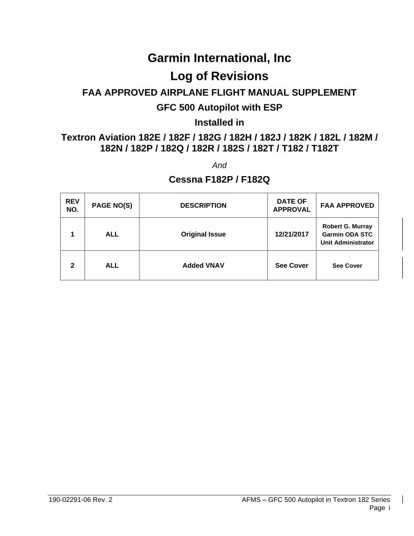
Garmin International, Inc
Log of Revisions
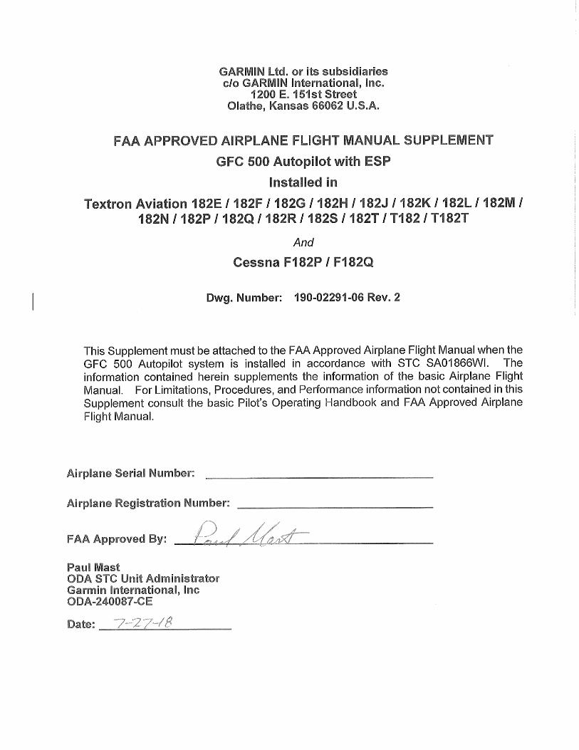
FAA APPROVED AIRPLANE FLIGHT MANUAL SUPPLEMENT
GFC 500 Autopilot with ESP
Installed in
Textron Aviation 182E / 182F / 182G / 182H / 182J / 182K / 182L / 182M / 182N / 182P / 182Q / 182R / 182S / 182T / T182 / T182T
And
Cessna F182P / F182Q
REV
NO. PAGE NO(S) DESCRIPTION
DATE OF
APPROVAL FAA APPROVED
1 ALL Original Issue 12/21/2017
Robert G. Murray
Garmin ODA STC
Unit Administrator
2 ALL Added VNAV See Cover See Cover

AFMS – GFC 500 Autopilot in Textron 182 Series 190-02291-06 Rev. 2
Page ii
This page intentionally left blank.
190-02291-06 Rev. 2 AFMS – GFC 500 Autopilot in Textron 182 Series
Page iii
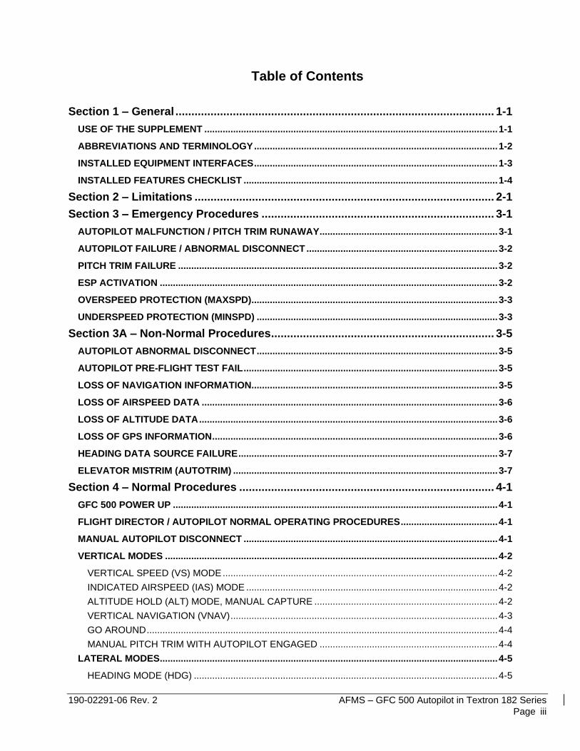
Table of Contents
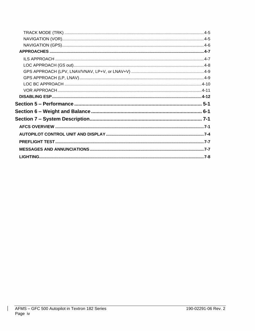
Section 1 – General .................................................................................................... 1-1
USE OF THE SUPPLEMENT ................................................................................................................ 1-1
ABBREVIATIONS AND TERMINOLOGY ............................................................................................. 1-2
INSTALLED EQUIPMENT INTERFACES ............................................................................................. 1-3
INSTALLED FEATURES CHECKLIST ................................................................................................. 1-4
Section 2 – Limitations .............................................................................................. 2-1
Section 3 – Emergency Procedures ......................................................................... 3-1
AUTOPILOT MALFUNCTION / PITCH TRIM RUNAWAY .................................................................... 3-1
AUTOPILOT FAILURE / ABNORMAL DISCONNECT ......................................................................... 3-2
PITCH TRIM FAILURE .......................................................................................................................... 3-2
ESP ACTIVATION ................................................................................................................................. 3-2
OVERSPEED PROTECTION (MAXSPD) .............................................................................................. 3-3
UNDERSPEED PROTECTION (MINSPD) ............................................................................................ 3-3
Section 3A – Non-Normal Procedures ...................................................................... 3-5
AUTOPILOT ABNORMAL DISCONNECT ............................................................................................ 3-5
AUTOPILOT PRE-FLIGHT TEST FAIL ................................................................................................. 3-5
LOSS OF NAVIGATION INFORMATION .............................................................................................. 3-5
LOSS OF AIRSPEED DATA ................................................................................................................. 3-6
LOSS OF ALTITUDE DATA .................................................................................................................. 3-6
LOSS OF GPS INFORMATION ............................................................................................................. 3-6
HEADING DATA SOURCE FAILURE ................................................................................................... 3-7
ELEVATOR MISTRIM (AUTOTRIM) ..................................................................................................... 3-7
Section 4 – Normal Procedures ................................................................................ 4-1
GFC 500 POWER UP ............................................................................................................................ 4-1
FLIGHT DIRECTOR / AUTOPILOT NORMAL OPERATING PROCEDURES ..................................... 4-1
MANUAL AUTOPILOT DISCONNECT ................................................................................................. 4-1
VERTICAL MODES ............................................................................................................................... 4-2
VERTICAL SPEED (VS) MODE ......................................................................................................... 4-2
INDICATED AIRSPEED (IAS) MODE ................................................................................................ 4-2
ALTITUDE HOLD (ALT) MODE, MANUAL CAPTURE ...................................................................... 4-2
VERTICAL NAVIGATION (VNAV) ...................................................................................................... 4-3
GO AROUND ...................................................................................................................................... 4-4
MANUAL PITCH TRIM WITH AUTOPILOT ENGAGED .................................................................... 4-4
LATERAL MODES ................................................................................................................................. 4-5
HEADING MODE (HDG) .................................................................................................................... 4-5
AFMS – GFC 500 Autopilot in Textron 182 Series 190-02291-06 Rev. 2
Page iv
TRACK MODE (TRK) ......................................................................................................................... 4-5
NAVIGATION (VOR) ........................................................................................................................... 4-5
NAVIGATION (GPS) ........................................................................................................................... 4-6
APPROACHES ...................................................................................................................................... 4-7
ILS APPROACH ................................................................................................................................. 4-7
LOC APPROACH (GS out) ................................................................................................................. 4-8
GPS APPROACH (LPV, LNAV/VNAV, LP+V, or LNAV+V) ............................................................... 4-9
GPS APPROACH (LP, LNAV) ............................................................................................................ 4-9
LOC BC APPROACH ....................................................................................................................... 4-10
VOR APPROACH ............................................................................................................................. 4-11
DISABLING ESP .................................................................................................................................. 4-12
Section 5 – Performance ........................................................................................... 5-1
Section 6 – Weight and Balance ............................................................................... 6-1
Section 7 – System Description ................................................................................ 7-1
AFCS OVERVIEW ................................................................................................................................. 7-1
AUTOPILOT CONTROL UNIT AND DISPLAY ..................................................................................... 7-4
PREFLIGHT TEST ................................................................................................................................. 7-7
MESSAGES AND ANNUNCIATIONS ................................................................................................... 7-7
LIGHTING............................................................................................................................................... 7-8
190-02291-06 Rev. 2 AFMS – GFC 500 Autopilot in Textron 182 Series
Page 1–1
SECTION 1 – GENERAL The information in this supplement is FAA-approved material and must be attached to the Pilot’s Operating
Handbook and FAA Approved Airplane Flight Manual (POH/AFM) when the airplane has been modified by
installation of the Garmin GFC 500 Autopilot system in accordance with Garmin International, Inc. approved data.
The information in this supplement supersedes or adds to the basic POH/AFM only as set forth below. Users of
the manual are advised to always refer to the supplement for possibly superseding information and placarding
applicable to operation of the airplane.
USE OF THE SUPPLEMENT
The following definitions apply to WARNINGS, CAUTIONS and NOTES found throughout the supplement:
Operating procedures, techniques, etc., which may result in personal injury or loss of life if not carefully followed.
CAUTION
Operating procedures, techniques, etc., which may result in damage to equipment if not carefully followed.
NOTE
Operating procedures, techniques, etc., which is considered essential to emphasize.
WARNING
AFMS – GFC 500 Autopilot in Textron 182 Series 190-02291-06 Rev. 2
Page 1–2
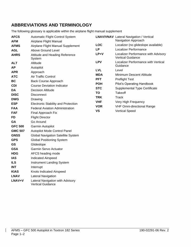
ABBREVIATIONS AND TERMINOLOGY
The following glossary is applicable within the airplane flight manual supplement
AFCS Automatic Flight Control System
AFM Airplane Flight Manual
AFMS Airplane Flight Manual Supplement
AGL Above Ground Level
AHRS Attitude and Heading Reference System
ALT Altitude
AP Autopilot
APR Approach
ATC Air Traffic Control
BC Back Course Approach
CDI Course Deviation Indicator
DA Decision Altitude
DISC Disconnect
DWG Drawing
ESP Electronic Stability and Protection
FAA Federal Aviation Administration
FAF Final Approach Fix
FD Flight Director
GA Go Around
GFC 500 Garmin Autopilot
GMC 507 Autopilot Mode Control Panel
GNSS Global Navigation Satellite System
GPS Global Positioning System
GS Glideslope
GSA Garmin Servo Actuator
HDG AFCS heading mode
IAS Indicated Airspeed
ILS Instrument Landing System
INT Interrupt
KIAS Knots Indicated Airspeed
LNAV Lateral Navigation
LNAV+V Lateral Navigation with Advisory Vertical Guidance
LNAV/VNAV Lateral Navigation / Vertical Navigation Approach
LOC Localizer (no glideslope available)
LP Localizer Performance
LP+V Localizer Performance with Advisory Vertical Guidance
LPV Localizer Performance with Vertical Guidance
LVL Level
MDA Minimum Descent Altitude
PFT Preflight Test
POH Pilot’s Operating Handbook
STC Supplemental Type Certificate
TO Takeoff
TRK Track
VHF Very High Frequency
VOR VHF Omni-directional Range
VS Vertical Speed
190-02291-06 Rev. 2 AFMS – GFC 500 Autopilot in Textron 182 Series
Page 1–3
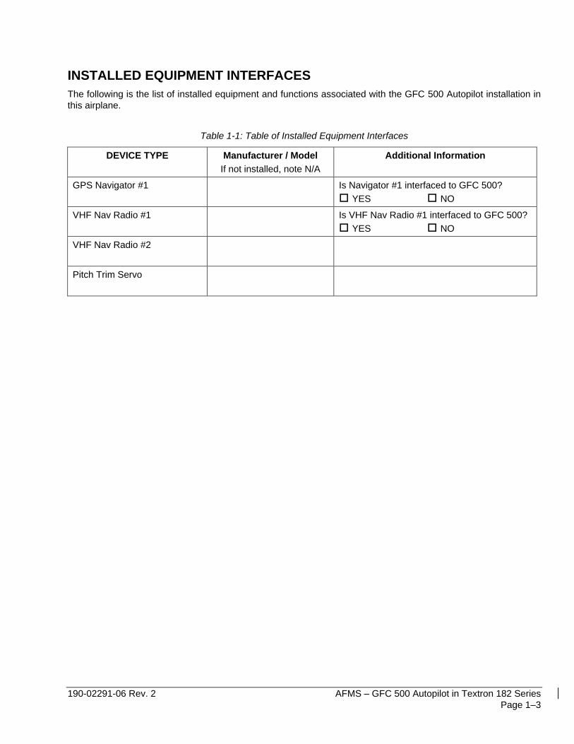
INSTALLED EQUIPMENT INTERFACES
The following is the list of installed equipment and functions associated with the GFC 500 Autopilot installation in
this airplane.
Table 1-1: Table of Installed Equipment Interfaces
DEVICE TYPE Manufacturer / Model
If not installed, note N/A
Additional Information
GPS Navigator #1
Is Navigator #1 interfaced to GFC 500?
YES NO
VHF Nav Radio #1
Is VHF Nav Radio #1 interfaced to GFC 500?
YES NO
VHF Nav Radio #2
Pitch Trim Servo
AFMS – GFC 500 Autopilot in Textron 182 Series 190-02291-06 Rev. 2
Page 1–4
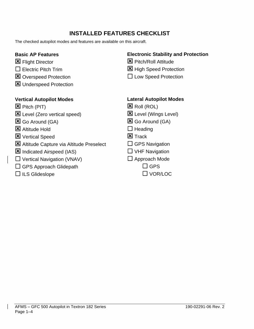
INSTALLED FEATURES CHECKLIST
The checked autopilot modes and features are available on this aircraft.
Basic AP Features
Flight Director
Electric Pitch Trim
Overspeed Protection
Underspeed Protection
Vertical Autopilot Modes
Pitch (PIT)
Level (Zero vertical speed)
Go Around (GA)
Altitude Hold
Vertical Speed
Altitude Capture via Altitude Preselect
Indicated Airspeed (IAS)
Vertical Navigation (VNAV)
GPS Approach Glidepath
ILS Glideslope
Electronic Stability and Protection
Pitch/Roll Attitude
High Speed Protection
Low Speed Protection
Lateral Autopilot Modes
Roll (ROL)
Level (Wings Level)
Go Around (GA)
Heading
Track
GPS Navigation
VHF Navigation
Approach Mode
GPS
VOR/LOC
190-02291-06 Rev. 2 AFMS – GFC 500 Autopilot in Textron 182 Series
Page 2–1
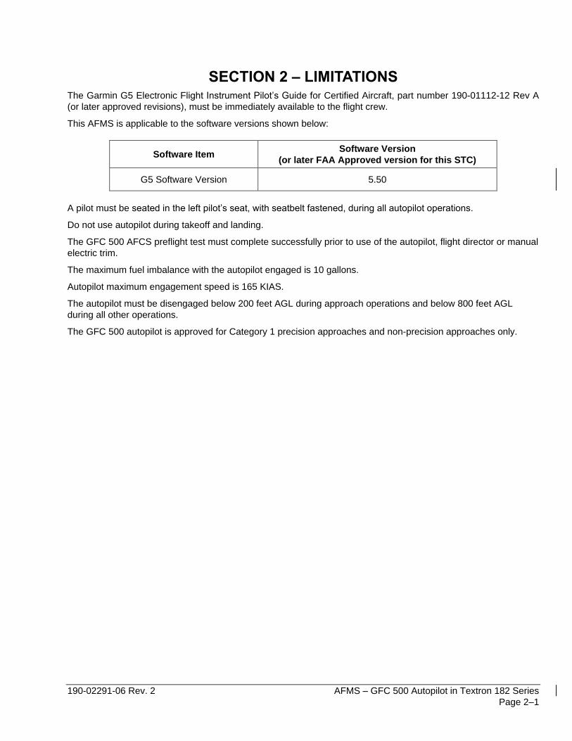
SECTION 2 – LIMITATIONS The Garmin G5 Electronic Flight Instrument Pilot’s Guide for Certified Aircraft, part number 190-01112-12 Rev A
(or later approved revisions), must be immediately available to the flight crew.
This AFMS is applicable to the software versions shown below:
Software Item Software Version
(or later FAA Approved version for this STC)
G5 Software Version 5.50
A pilot must be seated in the left pilot’s seat, with seatbelt fastened, during all autopilot operations.
Do not use autopilot during takeoff and landing.
The GFC 500 AFCS preflight test must complete successfully prior to use of the autopilot, flight director or manual
electric trim.
The maximum fuel imbalance with the autopilot engaged is 10 gallons.
Autopilot maximum engagement speed is 165 KIAS.
The autopilot must be disengaged below 200 feet AGL during approach operations and below 800 feet AGL
during all other operations.
The GFC 500 autopilot is approved for Category 1 precision approaches and non-precision approaches only.

AFMS – GFC 500 Autopilot in Textron 182 Series 190-02291-06 Rev. 2
Page 2–2
This page intentionally left blank.
190-02291-06 Rev. 2 AFMS – GFC 500 Autopilot in Textron 182 Series
Page 3–1
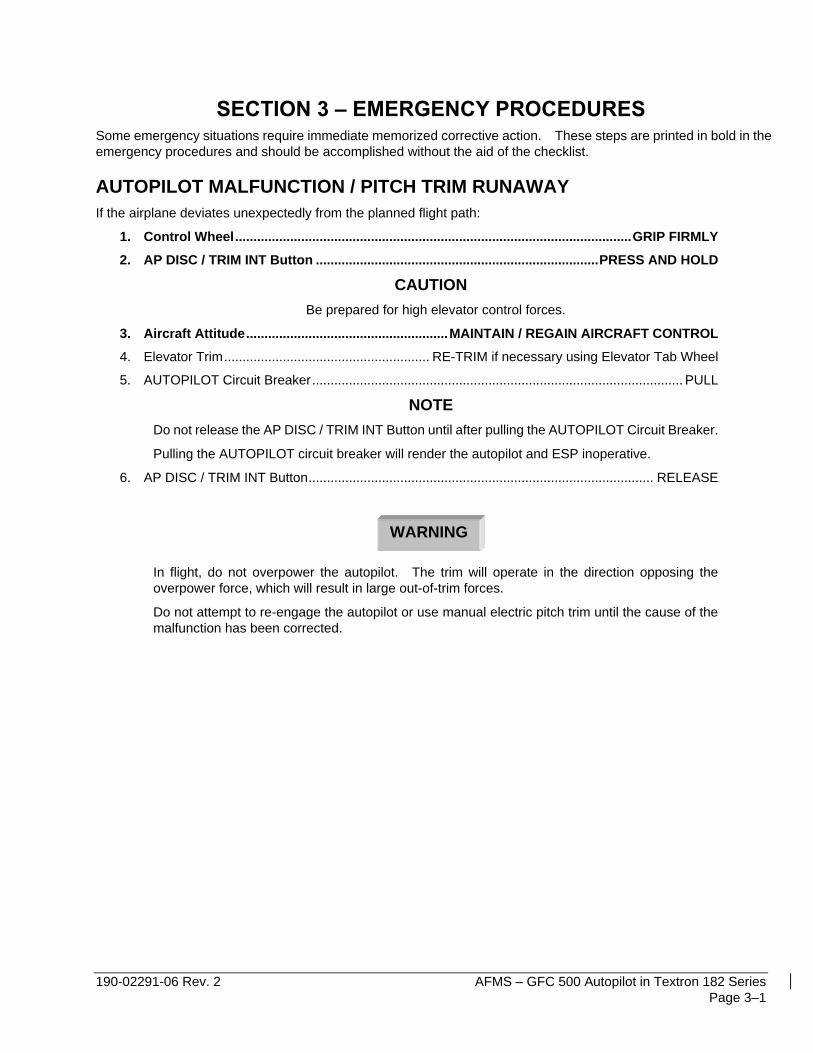
SECTION 3 – EMERGENCY PROCEDURES Some emergency situations require immediate memorized corrective action. These steps are printed in bold in the
emergency procedures and should be accomplished without the aid of the checklist.
AUTOPILOT MALFUNCTION / PITCH TRIM RUNAWAY
If the airplane deviates unexpectedly from the planned flight path:
1. Control Wheel ............................................................................................................ GRIP FIRMLY
2. AP DISC / TRIM INT Button ............................................................................. PRESS AND HOLD
CAUTION
Be prepared for high elevator control forces.
3. Aircraft Attitude ....................................................... MAINTAIN / REGAIN AIRCRAFT CONTROL
4. Elevator Trim ........................................................ RE-TRIM if necessary using Elevator Tab Wheel
5. AUTOPILOT Circuit Breaker ..................................................................................................... PULL
NOTE
Do not release the AP DISC / TRIM INT Button until after pulling the AUTOPILOT Circuit Breaker.
Pulling the AUTOPILOT circuit breaker will render the autopilot and ESP inoperative.
6. AP DISC / TRIM INT Button .............................................................................................. RELEASE
In flight, do not overpower the autopilot. The trim will operate in the direction opposing the
overpower force, which will result in large out-of-trim forces.
Do not attempt to re-engage the autopilot or use manual electric pitch trim until the cause of the
malfunction has been corrected.
WARNING
AFMS – GFC 500 Autopilot in Textron 182 Series 190-02291-06 Rev. 2
Page 3–2
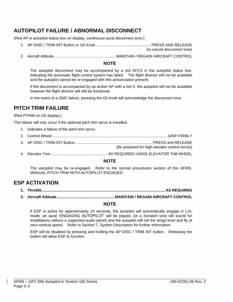
AUTOPILOT FAILURE / ABNORMAL DISCONNECT
(Red AP in autopilot status box on display, continuous aural disconnect tone.)
1. AP DISC / TRIM INT Button or G5 Knob .................................................... PRESS AND RELEASE (to cancel disconnect tone)
2. Aircraft Attitude ........................................................... MAINTAIN / REGAIN AIRCRAFT CONTROL
NOTE
The autopilot disconnect may be accompanied by a red AFCS in the autopilot status box,
indicating the automatic flight control system has failed. The flight director will not be available
and the autopilot cannot be re-engaged with this annunciation present.
If the disconnect is accompanied by an amber AP with a red X, the autopilot will not be available
however the flight director will still be functional.
In the event of a GMC failure, pressing the G5 knob will acknowledge the disconnect tone.
PITCH TRIM FAILURE
(Red PTRIM on G5 display.)
This failure will only occur if the optional pitch trim servo is installed.
1. Indicates a failure of the pitch trim servo.
2. Control Wheel ............................................................................................................. GRIP FIRMLY
3. AP DISC / TRIM INT Button .......................................................................... PRESS and RELEASE (Be prepared for high elevator control forces)
4. Elevator Trim ...................................................... AS REQUIRED USING ELEVATOR TAB WHEEL
NOTE
The autopilot may be re-engaged. Refer to the normal procedures section of this AFMS,
MANUAL PITCH TRIM WITH AUTOPILOT ENGAGED.
ESP ACTIVATION
1. Throttle ..................................................................................................................... AS REQUIRED
2. Aircraft Attitude ....................................................... MAINTAIN / REGAIN AIRCRAFT CONTROL
NOTE
If ESP is active for approximately 10 seconds, the autopilot will automatically engage in LVL
mode, an aural ‘ENGAGING AUTOPILOT’ will be played, (or a Sonalert tone will sound for
installations without a supported audio panel) and the autopilot will roll the wings level and fly at
zero-vertical speed. Refer to Section 7, System Description for further information.
ESP will be disabled by pressing and holding the AP DISC / TRIM INT button. Releasing the
button will allow ESP to function.
190-02291-06 Rev. 2 AFMS – GFC 500 Autopilot in Textron 182 Series
Page 3–3
OVERSPEED PROTECTION (MAXSPD)
(MAXSPD displayed on G5, AIRSPEED – AIRSPEED Aural sounds.)
1. Throttle ............................................................................................................................... REDUCE
2. Aircraft Attitude and Altitude ......................................................................................... MONITOR
After overspeed condition is corrected:
3. Autopilot .......................................RESELECT VERTICAL AND LATERAL MODES (if necessary)
4. Throttle ........................................................................................................... ADJUST as necessary
NOTE
Overspeed protection mode provides a pitch up command to decelerate the airplane at or below
the maximum autopilot operating speed.
UNDERSPEED PROTECTION (MINSPD)
(MINSPD displayed on G5, AIRSPEED – AIRSPEED Aural sounds.)
1. Throttle ............................... INCREASE POWER AS REQUIRED TO CORRECT UNDERSPEED
2. Aircraft Attitude and Altitude ......................................................................................... MONITOR
After underspeed condition is corrected:
3. Autopilot .........................................RESELECT VERTICAL AND LATERAL MODES (if necessary)
4. Throttle ........................................................................................................... ADJUST as necessary
NOTE
Autopilot Underspeed Protection Mode provides a pitch down command to maintain 65 KIAS.

AFMS – GFC 500 Autopilot in Textron 182 Series 190-02291-06 Rev. 2
Page 3–4
This page intentionally left blank.

190-02291-06 Rev. 2 AFMS – GFC 500 Autopilot in Textron 182 Series
Page 3–5
SECTION 3A – NON-NORMAL PROCEDURES
AUTOPILOT ABNORMAL DISCONNECT
(Red AP in the G5 autopilot status box, continuous aural disconnect tone.)
1. AP DISC / TRIM INT Button .........................................................................PRESS AND RELEASE (to cancel disconnect tone)
2. Aircraft Attitude ........................................................... MAINTAIN / REGAIN AIRCRAFT CONTROL
NOTE
The autopilot disconnect may be accompanied by a red AFCS in the autopilot status box,
indicating the automatic flight control system has failed. The flight director will not be available
and the autopilot cannot be re-engaged with this annunciation present.
If the disconnect is accompanied by an amber AP with a red X, the autopilot will not be available
however the flight director will still be functional.
AUTOPILOT PRE-FLIGHT TEST FAIL
(Amber AP with a red X in G5 autopilot status box.)
1. Indicates the AFCS system failed the automatic Pre-Flight test.
NOTE
The autopilot, ESP, and electric elevator trim are inoperative. Flight director will still function.
LOSS OF NAVIGATION INFORMATION
(Amber GPS, VOR, LOC, or BC flashes for 10 seconds on G5.)
NOTE
If a navigation signal is lost while the autopilot is tracking it, the autopilot will roll the aircraft
wings level and default to roll mode (ROL).
1. GMC 507 Mode Panel ............................................. SELECT HDG mode and SET desired heading
2. NAV Source ......................................................................................... SELECT a valid NAV source
3. NAV Key ................................................................................................................................. PRESS
If on an instrument approach at the time the navigation signal is lost:
4. Missed Approach Procedure .................................................................... EXECUTE (as applicable)
AFMS – GFC 500 Autopilot in Textron 182 Series 190-02291-06 Rev. 2
Page 3–6
LOSS OF AIRSPEED DATA
(Red X through airspeed tape on the G5 display, amber AP with a red X in autopilot status box.)
NOTE
If airspeed data is lost while the autopilot is tracking airspeed, the flight director will default to
pitch mode (PIT).
1. AP DISC / TRIM INT Button ........................................................................ PRESS AND RELEASE (to cancel disconnect tone)
2. Aircraft Attitude ........................................................... MAINTAIN / REGAIN AIRCRAFT CONTROL
3. Manual Elevator Trim ............................................................................................. TRIM as required
NOTE
The autopilot cannot be re-engaged. The flight director is available however IAS mode cannot
be selected. Loss of airspeed will be accompanied by a red PTRIM indication on the G5 (if a
pitch trim servo is installed).
LOSS OF ALTITUDE DATA
(Red X through altitude tape on the G5 display.)
NOTE
If altitude data is lost while the autopilot is tracking altitude, the autopilot will default to pitch mode
(PIT).
1. Autopilot .......................................................................................... SELECT different vertical mode
LOSS OF GPS INFORMATION
(GPS position information is lost to the autopilot.)
NOTE
If GPS position data is lost while the autopilot is tracking a GPS, VOR, LOC or BC course, the
autopilot will default to roll mode (ROL). The autopilot will default to pitch mode if GPS
information is lost while tracking an ILS. The autopilot uses GPS aiding in VOR, LOC and BC
modes.
1. Autopilot ................................................ SELECT different lateral and vertical mode (as necessary)
If on an instrument approach:
• AP DISC / TRIM INT button ................................... PRESS, Continue the approach manually
Or
• Missed Approach Procedure .......................................................... EXECUTE (as applicable)
190-02291-06 Rev. 2 AFMS – GFC 500 Autopilot in Textron 182 Series
Page 3–7
HEADING DATA SOURCE FAILURE
1. Autopilot ............................................................................................ SELECT different lateral mode
NOTE
Track information will be displayed on the G5.
Without a heading source to the navigator, GPSS will not be provided to the autopilot for
heading legs. Navigator map cannot be oriented heading up.
ELEVATOR MISTRIM (AUTOTRIM)
(Amber TRIM UP or TRIM DOWN displayed on the G5.)
Do not attempt to overpower the autopilot in the event of a pitch mistrim. The autopilot servo
will oppose pilot input and will cause pitch trim to run opposite the direction of pilot input. This
will lead to a significant out-of-trim condition, resulting in large control wheel force when
disengaging the autopilot.
NOTE
Indicates a mistrim of the elevator while the autopilot is engaged.
If a pitch trim servo is not installed, refer to the normal procedures section of this AFMS, MANUAL
PITCH TRIM WITH AUTOPILOT ENGAGED. If a pitch trim servo is installed, the autopilot will
normally trim the airplane as required. However, during rapid acceleration, deceleration,
configuration changes, or near either end of the elevator trim limits, momentary illumination of
this message may occur. If the autopilot is disconnected while this message is displayed, high
elevator control forces are possible.
If a pitch trim servo is not installed:
1. Refer to the normal procedures section of this AFMS, MANUAL PITCH TRIM WITH AUTOPILOT ENGAGED.
If a pitch trim servo is installed:
NOTE
Momentary display of the TRIM UP or TRIM DOWN message during configuration changes or
large airspeed changes is normal.
1. Control Wheel ............................................................................................................. GRIP FIRMLY
Be prepared for significant sustained control forces in the direction of the mistrim annunciation.
For example, TRIM DOWN indicates nose down control wheel force will be required upon
autopilot disconnect.
2. AP DISC / TRIM INT Button .........................................................................PRESS AND RELEASE
WARNING
WARNING

AFMS – GFC 500 Autopilot in Textron 182 Series 190-02291-06 Rev. 2
Page 3–8
3. Manual Elevator Trim ....................................................................................... RE-TRIM as required
Electric pitch trim should be considered inoperative until the cause of the mistrim has been investigated and
corrected.
190-02291-06 Rev. 2 AFMS – GFC 500 Autopilot in Textron 182 Series
Page 4–1
SECTION 4 – NORMAL PROCEDURES
GFC 500 POWER UP
During the preflight test the G5 will display PFT in the autopilot status box. The autopilot disconnect tone sounds
at the completion of the preflight test. When the GFC 500 passes preflight test, PFT will be removed from the
autopilot status box.
FLIGHT DIRECTOR / AUTOPILOT NORMAL OPERATING PROCEDURES
Autopilot/Flight Director mode annunciations are displayed at the top of the G5 Electronic Flight Instrument.
Green text indicates active autopilot/flight director modes. Armed modes are indicated in white text. Normal
mode transitions will flash inverse video for 10 seconds before becoming steady. Abnormal mode transitions will
flash for 10 seconds in amber text before the default mode is annunciated as the active mode in green text.
Default autopilot/flight director modes are Roll (ROL) and Pitch (PIT) modes.
The autopilot status box displays the autopilot engagement status as well as armed and active flight director
modes.
Autopilot Engagement with Flight Director Off — Upon engagement, the autopilot will be set to hold the
current attitude of the airplane if the flight director was not previously on. In this case, ‘ROL’ and ‘PIT’ will be
annunciated.
Autopilot Engagement with Flight Director On — If the flight director is on, the autopilot will smoothly pitch and
roll the airplane to capture the FD command bars. The prior flight director modes remain unchanged.
Autopilot Disengagement — The most common way to disconnect the autopilot is to press and release the AP
DISC / TRIM INT button located on the control yoke. An autopilot disconnect tone will sound and an amber AP
will be annunciated on the G5 autopilot status box. Other ways to disconnect the autopilot include:
– Pressing the AP Key on the GMC 507 Mode Controller
– Operating the Electric Pitch Trim Switch (located on the control wheel)
– Pulling the AUTOPILOT circuit breaker
In the event of unexpected autopilot behavior, press and holding the AP DISC / TRIM INT button will disconnect
the autopilot and remove all power to the servos.
MANUAL AUTOPILOT DISCONNECT
If necessary, the autopilot may be manually disconnected using any one of the following methods:
1. AP DISC / TRIM INT Button .......................................................................... PRESS and RELEASE (Pilot’s control wheel)
2. AP Key ................................................................................................................................... PRESS
3. Pitch Trim Switch ............................................................................................................. ACTIVATE
4. AUTOPILOT Circuit Breaker ..................................................................................................... PULL
AFMS – GFC 500 Autopilot in Textron 182 Series 190-02291-06 Rev. 2
Page 4–2
VERTICAL MODES
VERTICAL SPEED (VS) MODE
1. Altitude Preselect ......................................................................................... SET to Desired Altitude
2. Press VS Key, autopilot synchronizes to the airplane’s current vertical speed.
3. Vertical Speed Reference ............................................................... ADJUST using UP / DN Wheel
4. Green ALT ........................................................................................ VERIFY Upon Altitude Capture
INDICATED AIRSPEED (IAS) MODE
1. Altitude Preselect ......................................................................................... SET to Desired Altitude
2. Press IAS Key, autopilot synchronizes to the airplane’s current indicated airspeed.
3. AIRSPEED Reference ...................................................................... ADJUST using UP / DN Wheel
4. Throttle ................................................................................ ADJUST, INCREASE POWER to climb
DECREASE POWER to descend
5. Green ALT ........................................................................................ VERIFY Upon Altitude Capture
ALTITUDE HOLD (ALT) MODE, MANUAL CAPTURE
1. When at the desired altitude .................................................................................... PRESS ALT key
NOTE
If climbing or descending at a high rate when the ALT key is pressed, the airplane will overshoot
the reference altitude and then return to it. The amount of overshoot will depend on the vertical
speed when the ALT key is pressed.
The altitude reference is displayed in the autopilot status box. The reference may be changed
by +/- 200 FT using the UP / DN wheel.
190-02291-06 Rev. 2 AFMS – GFC 500 Autopilot in Textron 182 Series
Page 4–3
VERTICAL NAVIGATION (VNAV)
1. Navigation Source ............................................................................................ SELECT CDI to GPS
2. Vertical Navigation Profile ................................................ LOAD into the GPS navigator’s flight plan
3. Altitude Preselect ......................................................................... SET to the vertical clearance limit
When ATC clearance received.
4. GMC 507 Mode Panel ......................... PRESS VNAV within 5 minutes of the top of descent (TOD)
NOTE
Vertical navigation will not function for the following conditions:
• Selected navigation source is not GPS navigation. VNAV will not function if the navigation source
is VOR or Localizer.
• VNAV is not enabled on the GPS Navigator
• If the altitude preselect is not set below the current aircraft altitude.
• No waypoints with altitude constraints in the flight plan
• Glideslope or Glidepath is the active flight director pitch mode.
• OBS mode is active
• Dead Reckoning mode is active
• Parallel track is active
• Aircraft is on the ground
Vertical navigation is not available between the final approach fix (FAF) and the missed approach point
(MAP)
ALTV will be the armed vertical mode during the descent if the altitude preselect is set to a lower altitude
than the VNAV reference altitude. This indicates the autopilot / flight director will capture the VNAV altitude
reference. ALTS will be the armed mode during the descent if the altitude preselect is set at or above the
VNAV reference altitude, indicating that the autopilot / flight director will capture the altitude preselect
altitude reference.
AFMS – GFC 500 Autopilot in Textron 182 Series 190-02291-06 Rev. 2
Page 4–4
GO AROUND
1. GO AROUND button ....................................................................... PRESS – Verify GA / GA on G5
autopilot will not disengage
2. Autopilot (if engaged) ............... VERIFY airplane pitches up following flight director command bars
3. Throttle ...................................................................................................... APPLY Go Around power
4. GMC 507 Mode Panel .................................... PRESS NAV to couple to selected navigation source
OR PRESS HDG to Fly ATC Assigned Missed Approach Heading
5. Altitude Preselect .................................................................................................................. VERIFY
Set to appropriate altitude.
NOTE
The pilot is responsible for initial missed approach guidance in accordance with published
procedure. When the GA button is pressed the Flight Director command bars will command go-
around pitch attitude and wings level. The pilot must select the CDI to the appropriate navigation
source and select the desired lateral and vertical flight director modes.
MANUAL PITCH TRIM WITH AUTOPILOT ENGAGED
(Amber TRIM UP or TRIM DOWN displayed on G5.)
NOTE
If the aircraft is not equipped with a pitch trim servo, the pilot must manually adjust the pitch trim
when airspeed and aircraft configuration changes are made.
A message will be displayed on the G5 display to indicate the pitch servo is holding sustained force, and the pilot
must manually trim the aircraft.
1. If TRIM UP message is displayed ........................................................... MANUALLY TRIM nose up
2. If TRIM DOWN message is displayed ............................................... MANUALLY TRIM nose down
190-02291-06 Rev. 2 AFMS – GFC 500 Autopilot in Textron 182 Series
Page 4–5
LATERAL MODES
HEADING MODE (HDG)
1. HDG Key ................................................................................................................................ PRESS
The autopilot will turn the airplane in the direction of the heading bug.
2. HDG/TRK Knob ......................................................... Rotate to set heading bug to desired heading.
NOTE
If heading bug is reset too quickly, the airplane could turn in the opposite direction as the heading
bug’s movement.
TRACK MODE (TRK)
1. TRK Key ................................................................................................................................. PRESS
The autopilot will turn the airplane in the direction of the track bug.
2. HDG/TRK Knob ................................................................... Rotate to set track bug to desired track.
NOTE
If track bug is reset too quickly, the airplane could turn in the opposite direction as the track bug’s
movement.
NAVIGATION (VOR)
1. Navigation Source. ................................................................................. SELECT CDI to VHF NAV
Tune and identify the station frequency.
2. Course Pointer ............................................................................... SET CDI to the Desired Course
3. Intercept Heading ............................................................ ESTABLISH in HDG, TRK or ROL mode
4. NAV Key ................................................................................................................................. PRESS
NOTE
If the Course Deviation Indicator (CDI) is greater than one dot from center, the autopilot will arm
the VOR mode. The pilot must ensure that the current heading will result in a capture of the
selected course. If the CDI is one dot or less from center, the autopilot will enter the capture
mode when the NAV key is pressed.
AFMS – GFC 500 Autopilot in Textron 182 Series 190-02291-06 Rev. 2
Page 4–6
NAVIGATION (GPS)
1. Navigation Source ............................................................................................ SELECT CDI to GPS
2. Waypoint .......................................................................................... SELECT on Navigation Source
3. Course Pointer ..................................................................... VERIFY CDI set to the Desired Course
4. Intercept Heading ........................................................................ ESTABLISH in HDG or ROL mode
5. NAV Key ................................................................................................................................. PRESS
NOTE
If the Course Deviation Indicator (CDI) is greater than one dot from center, the autopilot will arm
the GPS mode. The pilot must ensure that the current heading will result in a capture of the
selected course. If the CDI is one dot or less from center, the autopilot will enter the capture mode
when the NAV key is pressed.
190-02291-06 Rev. 2 AFMS – GFC 500 Autopilot in Textron 182 Series
Page 4–7
APPROACHES
ILS APPROACH
1. Navigation Source. .................................................................................... SELECT CDI to VHF Nav
Tune and Identify an ILS station frequency.
2. CDI ............................................................................................................. SET to front LOC course
NOTE
Ensure that the current heading will result in a capture of the selected course.
3. APR Key .................................................................................. PRESS, verify LOC and GS ARMED
4. LOC and GS Mode .......................................... VERIFY airplane Captures and Tracks LOC and GS
5. Missed Approach Altitude ......................................................................... SET in Altitude preselect.
At Decision Altitude (DA),
6. AP DISC / TRIM INT button .................................... PRESS, Continue visually for a normal landing
Or
7. GO AROUND (GA) button ....................................... PRESS, Execute Missed Approach Procedure
8. Apply GA power.
NOTE
Pressing the GA button will not disconnect the autopilot. Select NAV or HDG mode to fly the
missed approach procedure.
If the Course Deviation Indicator (CDI) is greater than half scale deflection, the autopilot will arm
the LOC mode. The pilot must ensure that the current heading will result in a capture of the
selected course. If the CDI is within half scale deflection, the autopilot will enter the capture
mode when the APR key is pressed.
When the selected navigation source is an ILS, glideslope coupling is automatically armed when
the APR key is pressed. The glideslope cannot be captured until the localizer is captured. The
autopilot can capture the glideslope from above or below the glideslope.
AFMS – GFC 500 Autopilot in Textron 182 Series 190-02291-06 Rev. 2
Page 4–8
LOC APPROACH (GS out)
1. Navigation Source ..................................................................................... SELECT CDI to VHF Nav
Tune and Identify an ILS station frequency.
2. Course Pointer ........................................................................................... SET to front LOC course
NOTE
Ensure that the current heading will result in a capture of the selected course.
3. NAV Key ................................................................................................ PRESS, verify LOC ARMED
4. LOC Mode ....................................................... VERIFY airplane Captures and Tracks LOC Course
5. Altitude Preselect ................................................................ SET to next required step down altitude
6. Missed Approach Altitude ......................................................... SET when in ALT mode at the MDA
At Missed Approach Point,
7. AP DISC / TRIM INT button .................................... PRESS, Continue visually for a normal landing
Or
8. GO AROUND (GA) button ....................................... PRESS, Execute Missed Approach Procedure
9. Apply GA power.
NOTE
Pressing the GA button will not disconnect the autopilot. Select NAV or HDG mode to fly the
missed approach procedure.
190-02291-06 Rev. 2 AFMS – GFC 500 Autopilot in Textron 182 Series
Page 4–9
GPS APPROACH (LPV, LNAV/VNAV, LP+V, or LNAV+V)
1. Navigation Source ............................................................................................ SELECT CDI to GPS
2. Course Pointer ..................................................................... VERIFY CDI set to the Desired Course
NOTE
Ensure that the current heading will result in a capture of the selected course.
3. APR Key .................................................................................. PRESS, verify GPS and GP ARMED
4. GPS and GP Mode ......................................... VERIFY airplane Captures and Tracks GPS and GP
5. ALT Key ...................................... PRESS to level off at the MDA for a LP+V or LNAV+V approach
At DA (LPV or LNAV/VNAV approach), or MDA and Missed Approach Point (LP+V or LNAV+V),
6. AP DISC / TRIM INT button .................................... PRESS, Continue visually for a normal landing
Or
7. GO AROUND (GA) button ....................................... PRESS, Execute Missed Approach Procedure
8. Apply GA power.
9. Set missed approach altitude in the altitude preselect.
NOTE
Pressing the GA button will not disconnect the autopilot. Select NAV or HDG mode to fly the
missed approach procedure.
GPS APPROACH (LP, LNAV)
1. Navigation Source ..................................................................................... SELECT GPS on the CDI
2. Course Pointer .................................................................... VERIFY CDI set on the Desired Course
NOTE
Ensure that the current heading will result in a capture of the selected course.
3. NAV Key ............................................................................................... PRESS, verify GPS ARMED
4. GPS Mode ....................................................... VERIFY airplane Captures and Tracks GPS Course
5. Altitude Preselect ................................................................ SET to next required step down altitude
6. Missed Approach Altitude ......................................................... SET when in ALT mode at the MDA
At Missed Approach Point,
7. AP DISC / TRIM INT button .................................... PRESS, Continue visually for a normal landing
Or
8. GO AROUND (GA) button ....................................... PRESS, Execute Missed Approach Procedure
9. Apply GA power.
NOTE
Pressing the GA button will not disconnect the autopilot. Select NAV or HDG mode to fly the
missed approach procedure.
AFMS – GFC 500 Autopilot in Textron 182 Series 190-02291-06 Rev. 2
Page 4–10
LOC BC APPROACH
1. Navigation Source. .................................................................................... SELECT CDI to VHF Nav Tune and Identify an ILS station frequency
2. Course Pointer .................................................................................. SET CDI to LOC Front Course
NOTE
Ensure that the current heading will result in a capture of the selected course.
3. NAV Key .................................................................................................. PRESS, verify BC ARMED
(when heading is within 75 degrees of BC course)
4. BC Mode ............................................................ VERIFY airplane Captures and Tracks BC Course
5. Altitude Preselect ................................................................ SET to next required step down altitude
6. Missed Approach Altitude ......................................................... SET when in ALT mode at the MDA
At Missed Approach Point:
7. AP DISC / TRIM INT button .................................... PRESS, Continue visually for a normal landing
Or
8. GO AROUND (GA) button ....................................... PRESS, Execute Missed Approach Procedure
9. Apply GA power.
NOTE
Pressing the GA button will not disconnect the autopilot. Select NAV or HDG mode to fly the
missed approach procedure.
190-02291-06 Rev. 2 AFMS – GFC 500 Autopilot in Textron 182 Series
Page 4–11
VOR APPROACH
1. Navigation Source. .................................................................................... SELECT CDI to VHF Nav Tune and identify the station frequency
2. Course Pointer ................................................................................. SET CDI to the Desired Course
NOTE
Ensure that the current heading will result in a capture of the selected course.
3. NAV Key ............................................................................................... PRESS, verify VOR ARMED
4. VOR Mode ...................................................... VERIFY airplane Captures and Tracks VOR Course
5. Altitude Preselect ................................................................ SET to next required step down altitude
6. Missed Approach Altitude ......................................................... SET when in ALT mode at the MDA
At Missed Approach Point,
7. AP DISC / TRIM INT button .................................... PRESS, Continue visually for a normal landing
Or
8. GO AROUND (GA) button ....................................... PRESS, Execute Missed Approach Procedure
9. Apply GA power.
NOTE
Pressing the GA button will not disconnect the autopilot. Select NAV or HDG mode to fly the
missed approach procedure.

AFMS – GFC 500 Autopilot in Textron 182 Series 190-02291-06 Rev. 2
Page 4–12
DISABLING ESP
ESP can be disabled on the G5 attitude indicator with the following procedure. ESP will default to “Enabled” on
the next power cycle.
1. G5 Knob. ................................................................................................................................ PRESS
2. ESP ...................................................................................................................................... SELECT
3. G5 Knob ................................................................................................................................. PRESS

190-02291-06 Rev. 2 AFMS – GFC 500 Autopilot in Textron 182 Series
Page 5–1
SECTION 5 – PERFORMANCE No Change.

AFMS – GFC 500 Autopilot in Textron 182 Series 190-02291-06 Rev. 2
Page 5–2
This page intentionally left blank.

190-02291-06 Rev. 2 AFMS – GFC 500 Autopilot in Textron 182 Series
Page 6–1
SECTION 6 – WEIGHT AND BALANCE No change to loading information. Refer to current weight and balance report and equipment list for changes to
empty weight/moment and installed equipment.

AFMS – GFC 500 Autopilot in Textron 182 Series 190-02291-06 Rev. 2
Page 6–2
This page intentionally left blank.
190-02291-06 Rev. 2 AFMS – GFC 500 Autopilot in Textron 182 Series
Page 7–1
SECTION 7 – SYSTEM DESCRIPTION
AFCS OVERVIEW
The GFC 500 is a digital Automatic Flight Control System (AFCS). It is a two-axis autopilot and flight director
system which provides the pilot with the following features:
G5 Outputs to Autopilot — The G5 flight instrument provides attitude, rate, and acceleration information to the
servos. Additionally, indicated airspeed, vertical speed, pressure altitude and GPS information are sent to the
autopilot for mode control.
Flight Director (FD) — The flight director processing occurs in the G5 instrument. Selected modes for the flight
director are displayed on the G5 autopilot status box.
The flight director provides:
• Command Bars showing pitch/roll guidance
• Vertical / lateral mode selection and processing
Autopilot (AP) — Autopilot operation occurs within the pitch, roll, and optional pitch trim servo. It also provides servo monitoring, and automatic flight control in response to flight director steering commands, attitude and rate information, and airspeed.
Optional Electric Pitch Trim — The pitch trim servo provides manual electric pitch trim capability when the autopilot is not engaged. The trim servo provides automatic pitch trim when the autopilot is engaged and the airplane is in the air. Automatic trim functionality is disabled on the ground.
GMC 507 — Pilot commands to the autopilot and flight director are entered through the GMC 507 autopilot mode panel. The GMC 507 contains internal sensors which calculate the aircraft attitude, attitude rate and accelerations. These inertial sensors are completely independent from the sensors within the G5 and the rest of the autopilot system, and are not used for the flight director, autopilot, trim or ESP functions. They are used solely to provide independent monitoring of the GFC 500.
Airspeed and Altitude Information — The GFC 500 requires airspeed and altitude information from the G5 instrument.
Other components of the AFCS include the GSA 28 pitch, roll, and optional pitch trim servo that also contain autopilot processors, control wheel mounted elevator trim switch (if trim servo is installed), control wheel mounted autopilot disconnect and trim interrupt button (AP DISC / TRIM INT), and a Go-Around (GA) button.
Underspeed Protection (USP) — The GFC 500 will provide Underspeed Protection when the autopilot is
engaged.
When the minimum airspeed of 65 KIAS is reached, a visual MINSPD message will appear above the airspeed
tape and the autopilot will lower the nose to maintain 65 KIAS. An aural “AIRSPEED, AIRSPEED” voice alert will
sound for installations connected to an audio panel.
Underspeed Protection is exited automatically when airspeed exceeds 70 KIAS.
Overspeed Protection (OSP) — The GFC 500 will provide Overspeed Protection when the autopilot is engaged.
When the maximum airspeed of 165 KIAS is reached, visual MAXSPD message will appear above the airspeed
tape and the autopilot will raise the nose of the aircraft to avoid exceeding the maximum configured airspeed.
An aural “AIRSPEED, AIRSPEED” voice alert will sound for installations connected to an audio panel.
Overspeed Protection is exited automatically when airspeed is reduced below 160 KIAS.
Coupled Go-Around — Pressing the GA button will not disengage the autopilot. Instead, the autopilot will
attempt to capture and track the flight director command bars. If insufficient airplane performance is available to
follow the commands, the autopilot will enter Underspeed Protection mode at the minimum airspeed.
Electronic Stability and Protection (ESP) — The GFC 500 will provide Electronic Stability and Protection when
the autopilot is not engaged.
AFMS – GFC 500 Autopilot in Textron 182 Series 190-02291-06 Rev. 2
Page 7–2
Electronic Stability and Protection (ESP) uses the autopilot servos to assist the pilot in maintaining the airplane in
a safe flight condition within the airplane’s normal pitch, roll and airspeed envelopes.
Electronic Stability and Protection is invoked when the pilot allows the airplane to exceed one or more conditions
beyond normal flight defined below:
• Pitch attitude beyond normal flight (+20°, -15°)
• Roll attitude beyond normal flight (45°)
• High airspeed beyond normal flight (above 176 KIAS)
• Low airspeed below normal flight (below 60 KIAS)
The conditions that are required for ESP to be available are:
• Pitch and Roll servos available
• Autopilot not engaged
• The GPS altitude above ground is more than 200 feet (for low airspeed mode)
• Aircraft is within the autopilot engagement envelope (+/-50° in pitch and +/-75° in roll)
Protection for excessive Pitch, Roll, and Airspeed is provided when the limit thresholds are first exceeded, which
engages the appropriate servo in ESP mode at a nominal torque level to bring the airplane back within the normal
flight envelope. If the airplane deviates further from the normal flight envelope, the servo torque will increase
until the maximum torque level is reached in an attempt to return the airplane into the normal flight envelope.
Once the airplane returns to within the normal flight envelope, ESP will deactivate the autopilot servos.
When the normal flight envelope thresholds have been exceeded for more than 10 seconds, ESP Autolevel Mode
is activated. Autolevel Mode engages the autopilot to bring the airplane back into straight and level flight based
on 0° roll angle and 0 FPM vertical speed. An aural “ENGAGING AUTOPILOT” alert (or a Sonalert tone) sounds
and the Flight Director mode annunciation will indicate LVL for the pitch and roll modes.
Anytime an ESP mode is active, the pilot can interrupt ESP by using the Autopilot Disconnect (AP DISC / TRIM
INT) switch, or simply override ESP by overpowering the autopilot servos. The pilot may also disable ESP
through the G5 menu.
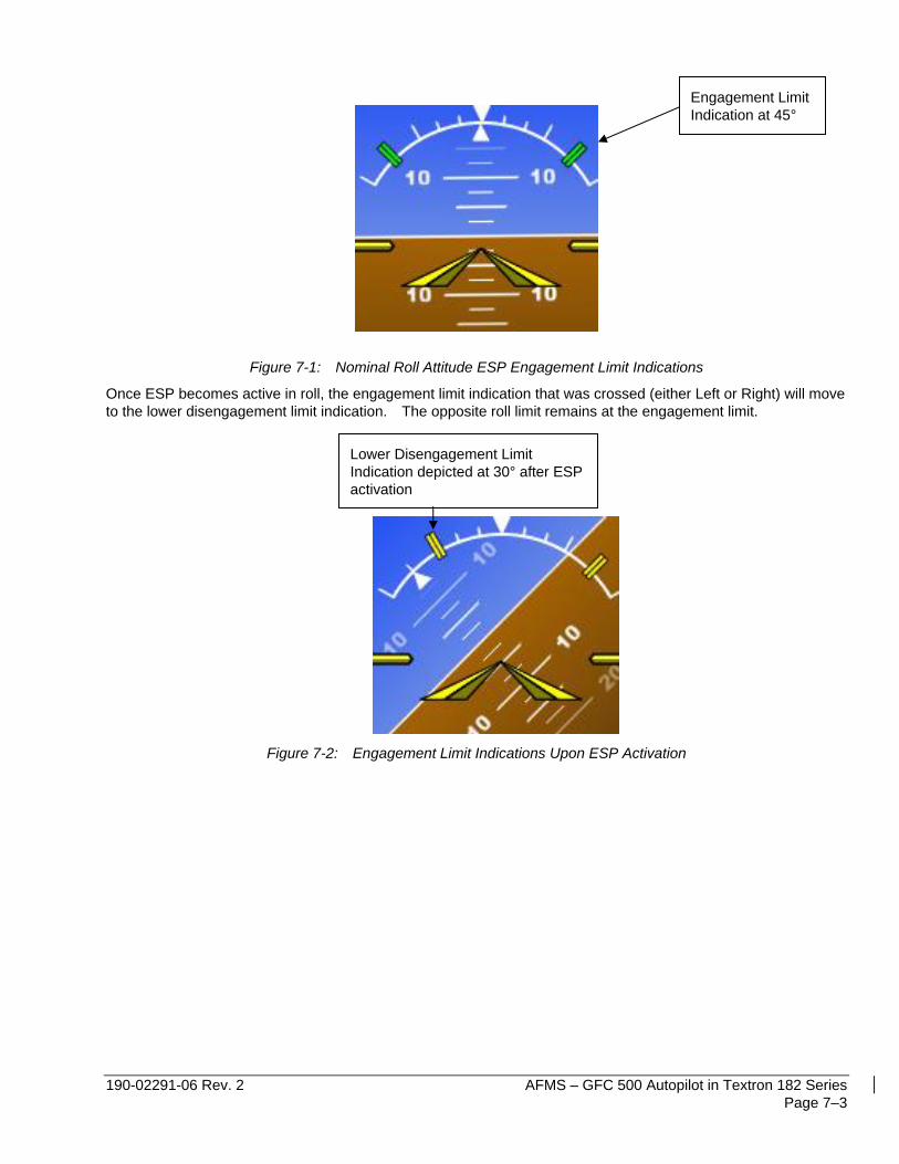
The engagement and disengagement attitude limits are displayed with double hash marks on the roll indicator
depending on the airplane attitude and whether or not ESP is active in roll. When ESP is inactive (roll attitude
within nominal limits) only the engagement limit indications are displayed in order to reduce clutter on the roll
indicator.
Display symbology implemented for ESP is illustrated in the following figures.
190-02291-06 Rev. 2 AFMS – GFC 500 Autopilot in Textron 182 Series
Page 7–3
Figure 7-1: Nominal Roll Attitude ESP Engagement Limit Indications
Once ESP becomes active in roll, the engagement limit indication that was crossed (either Left or Right) will move
to the lower disengagement limit indication. The opposite roll limit remains at the engagement limit.
Figure 7-2: Engagement Limit Indications Upon ESP Activation
Engagement Limit
Indication at 45°
Lower Disengagement Limit
Indication depicted at 30° after ESP
activation
AFMS – GFC 500 Autopilot in Textron 182 Series 190-02291-06 Rev. 2
Page 7–4
Disconnect Methods
The following conditions will cause the autopilot to automatically disconnect:
• Electrical power failure, including pulling the AUTOPILOT circuit breaker.
• Internal autopilot system failure (including internal AHRS failure).
The following pilot actions will cause the autopilot to disconnect:
• Pressing the red AP DISC / TRIM INT button on the pilot’s control wheel.
• Actuating the manual electric trim switch (if installed).
• Pushing the AP Key on the GMC 507 mode controller when the autopilot is engaged.
• Pulling the AUTOPILOT circuit breaker.
The red AP DISC / TRIM INT button on the pilot’s control wheel will interrupt power to the manual electric trim for
as long as the switch is depressed.
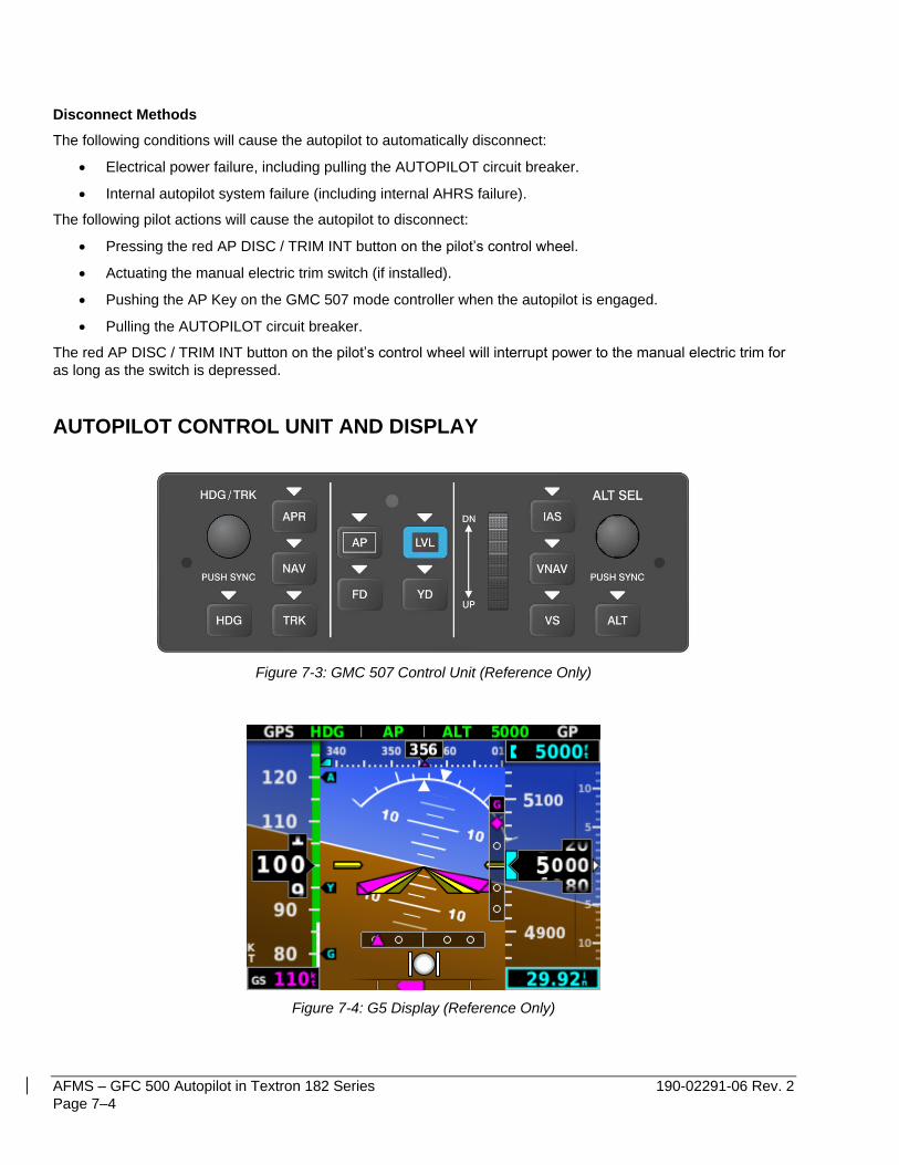
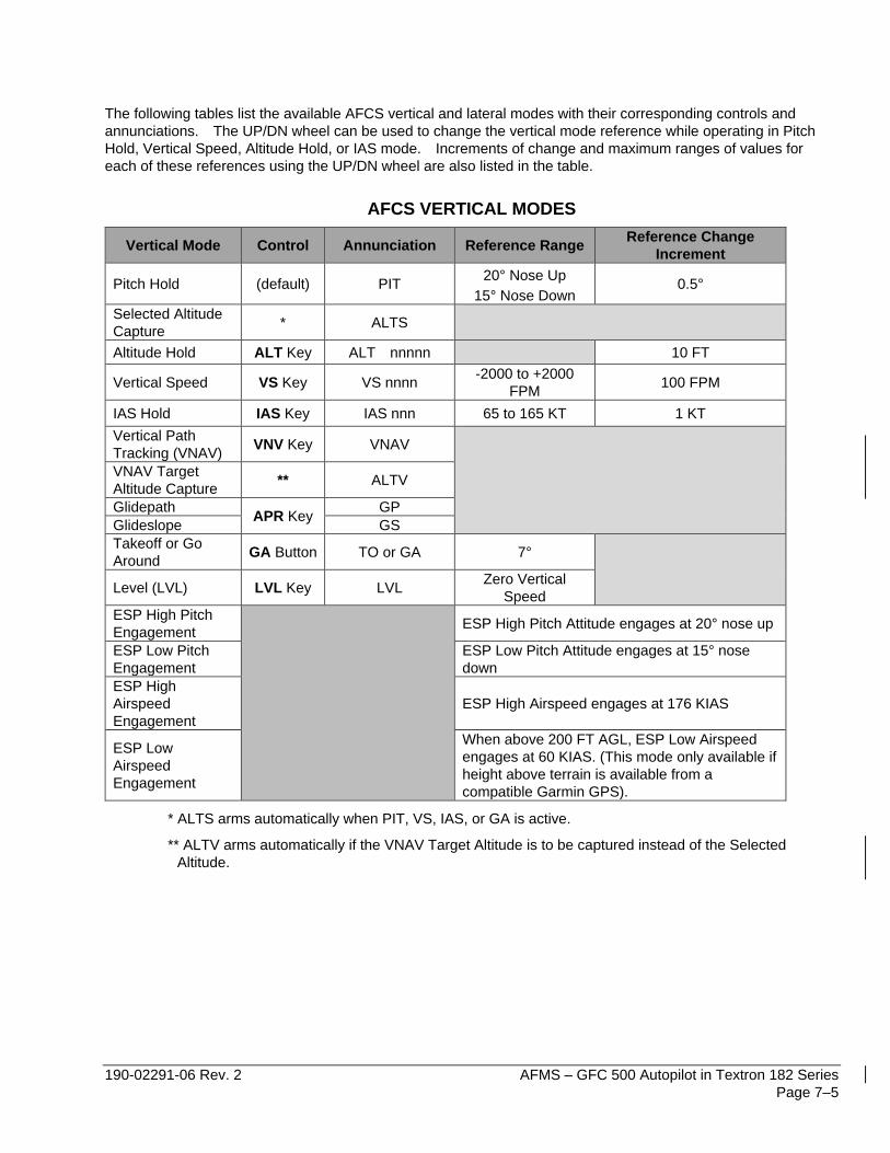
AUTOPILOT CONTROL UNIT AND DISPLAY
Figure 7-3: GMC 507 Control Unit (Reference Only)
Figure 7-4: G5 Display (Reference Only)
190-02291-06 Rev. 2 AFMS – GFC 500 Autopilot in Textron 182 Series
Page 7–5
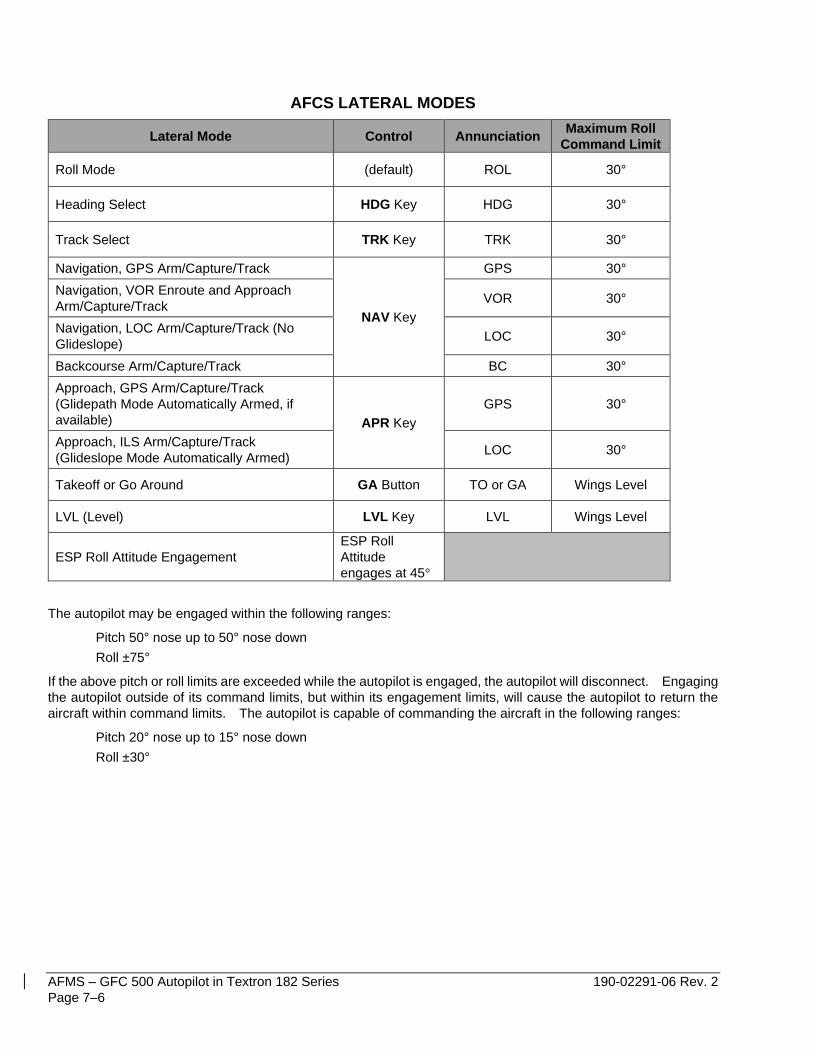
The following tables list the available AFCS vertical and lateral modes with their corresponding controls and
annunciations. The UP/DN wheel can be used to change the vertical mode reference while operating in Pitch
Hold, Vertical Speed, Altitude Hold, or IAS mode. Increments of change and maximum ranges of values for
each of these references using the UP/DN wheel are also listed in the table.
AFCS VERTICAL MODES
Vertical Mode Control Annunciation Reference Range Reference Change
Increment
Pitch Hold (default) PIT 20° Nose Up
15° Nose Down 0.5°
Selected Altitude
Capture * ALTS
Altitude Hold ALT Key ALT nnnnn 10 FT
Vertical Speed VS Key VS nnnn -2000 to +2000
FPM 100 FPM
IAS Hold IAS Key IAS nnn 65 to 165 KT 1 KT
Vertical Path
Tracking (VNAV) VNV Key VNAV
VNAV Target
Altitude Capture ** ALTV
Glidepath APR Key
GP
Glideslope GS
Takeoff or Go
Around GA Button TO or GA 7°
Level (LVL) LVL Key LVL Zero Vertical
Speed
ESP High Pitch
Engagement
ESP High Pitch Attitude engages at 20° nose up
ESP Low Pitch
Engagement
ESP Low Pitch Attitude engages at 15° nose
down
ESP High
Airspeed
Engagement
ESP High Airspeed engages at 176 KIAS
ESP Low
Airspeed
Engagement
When above 200 FT AGL, ESP Low Airspeed
engages at 60 KIAS. (This mode only available if
height above terrain is available from a
compatible Garmin GPS).
* ALTS arms automatically when PIT, VS, IAS, or GA is active.
** ALTV arms automatically if the VNAV Target Altitude is to be captured instead of the Selected
Altitude.
AFMS – GFC 500 Autopilot in Textron 182 Series 190-02291-06 Rev. 2
Page 7–6
AFCS LATERAL MODES
Lateral Mode Control Annunciation Maximum Roll
Command Limit
Roll Mode (default) ROL 30°
Heading Select HDG Key HDG 30°
Track Select TRK Key TRK 30°
Navigation, GPS Arm/Capture/Track
NAV Key
GPS 30°
Navigation, VOR Enroute and Approach
Arm/Capture/Track VOR 30°
Navigation, LOC Arm/Capture/Track (No
Glideslope) LOC 30°
Backcourse Arm/Capture/Track BC 30°
Approach, GPS Arm/Capture/Track
(Glidepath Mode Automatically Armed, if
available) APR Key
GPS 30°
Approach, ILS Arm/Capture/Track
(Glideslope Mode Automatically Armed) LOC 30°
Takeoff or Go Around GA Button TO or GA Wings Level
LVL (Level) LVL Key LVL Wings Level
ESP Roll Attitude Engagement
ESP Roll
Attitude
engages at 45°
The autopilot may be engaged within the following ranges:
Pitch 50° nose up to 50° nose down
Roll ±75°
If the above pitch or roll limits are exceeded while the autopilot is engaged, the autopilot will disconnect. Engaging
the autopilot outside of its command limits, but within its engagement limits, will cause the autopilot to return the
aircraft within command limits. The autopilot is capable of commanding the aircraft in the following ranges:
Pitch 20° nose up to 15° nose down
Roll ±30°
190-02291-06 Rev. 2 AFMS – GFC 500 Autopilot in Textron 182 Series
Page 7–7
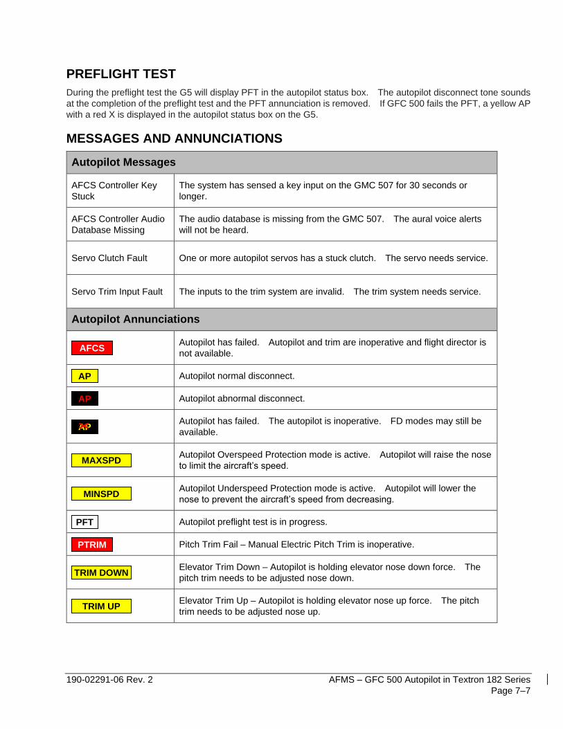
PREFLIGHT TEST
During the preflight test the G5 will display PFT in the autopilot status box. The autopilot disconnect tone sounds
at the completion of the preflight test and the PFT annunciation is removed. If GFC 500 fails the PFT, a yellow AP
with a red X is displayed in the autopilot status box on the G5.
MESSAGES AND ANNUNCIATIONS
Autopilot Messages
AFCS Controller Key
Stuck
The system has sensed a key input on the GMC 507 for 30 seconds or
longer.
AFCS Controller Audio
Database Missing
The audio database is missing from the GMC 507. The aural voice alerts
will not be heard.
Servo Clutch Fault One or more autopilot servos has a stuck clutch. The servo needs service.
Servo Trim Input Fault The inputs to the trim system are invalid. The trim system needs service.
Autopilot Annunciations
Autopilot has failed. Autopilot and trim are inoperative and flight director is
not available.
Autopilot normal disconnect.
Autopilot abnormal disconnect.
Autopilot has failed. The autopilot is inoperative. FD modes may still be
available.
Autopilot Overspeed Protection mode is active. Autopilot will raise the nose
to limit the aircraft’s speed.
Autopilot Underspeed Protection mode is active. Autopilot will lower the
nose to prevent the aircraft’s speed from decreasing.
Autopilot preflight test is in progress.
Pitch Trim Fail – Manual Electric Pitch Trim is inoperative.
Elevator Trim Down – Autopilot is holding elevator nose down force. The
pitch trim needs to be adjusted nose down.
Elevator Trim Up – Autopilot is holding elevator nose up force. The pitch
trim needs to be adjusted nose up.
AFCS
AP
AP
AP
MAXSPD
MINSPD
PFT
PTRIM
TRIM DOWN
TRIM UP

AFMS – GFC 500 Autopilot in Textron 182 Series 190-02291-06 Rev. 2
Page 7–8
LIGHTING
When the aircraft’s dimming bus is selected off, or full dim, GMC 507 mode control panel lighting is controlled by
integrated photocells which sense the ambient cockpit lighting.


![[Confidential] Textron - PatentStatus Demo](https://static.fdocuments.us/doc/165x107/55c32f35bb61ebd4488b4682/confidential-textron-patentstatus-demo.jpg)


