AFEII update (first 224 TriP channels) Juan Estrada Paul Rubinov
17
AFEII update (first 224 TriP channels) Juan Estrada Paul Rubinov
-
Upload
elvis-gilbert -
Category
Documents
-
view
19 -
download
0
description
AFEII update (first 224 TriP channels) Juan Estrada Paul Rubinov. Working TriP Chips. 1 bad TriP chip. MCMIIc (32ch.). MCMIIb (64ch.). MCMIIb. FPGA. JTAG cable (temporary solution). 2 ADCs. DIGITAL. ANALOG. 2 TriP chips inside. Charge injection connector. - PowerPoint PPT Presentation
Transcript of AFEII update (first 224 TriP channels) Juan Estrada Paul Rubinov
AFEII update(first 224 TriP channels)
Juan Estrada Paul Rubinov

Working TriP Chips
MCMIIb (64ch.)
MCMIIc (32ch.)
1 bad TriP chip

MCMIIb
2 TriP chips inside
2 ADCs
FPGA
JTAG cable(temporary solution)
Charge injectionconnector
DIGITALANALOG
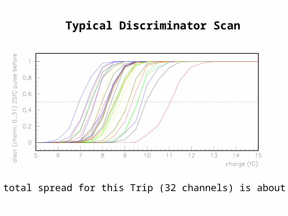
Typical Discriminator Scan
The total spread for this Trip (32 channels) is about 4 fC
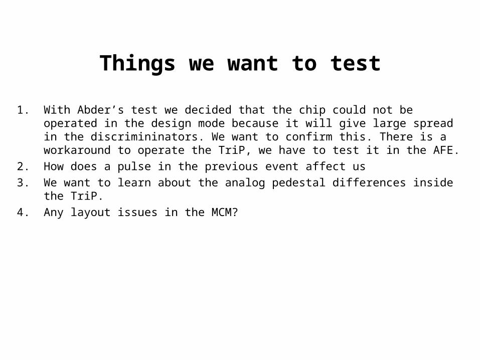
Things we want to test
1. With Abder’s test we decided that the chip could not be operated in the design mode because it will give large spread in the discrimininators. We want to confirm this. There is a workaround to operate the TriP, we have to test it in the AFE.
2. How does a pulse in the previous event affect us
3. We want to learn about the analog pedestal differences inside the TriP.
4. Any layout issues in the MCM?

Design operating mode/workaround
What you need to know to understand the problem:
• The trip has 16 discriminator outputs and 32 channels. DIGENUP and DIGENLOW choose which bank is at the output.
• The discriminators in the trip are always high (1) and go low (0) when they fire.
• The discriminators in the trip are also low (0) when no bank is enable.
Design operating mode:
During the reset (no integration time) one would enable DIGENUP and DIGENLOW. During integration time both are disable. This produces the 16 outputs to swing from at the same time when no discriminator has fired. This swing produces a transient signal that generates noise.
Workaround:
Have always one bank enable. The discriminators can fire in the integration window affecting.
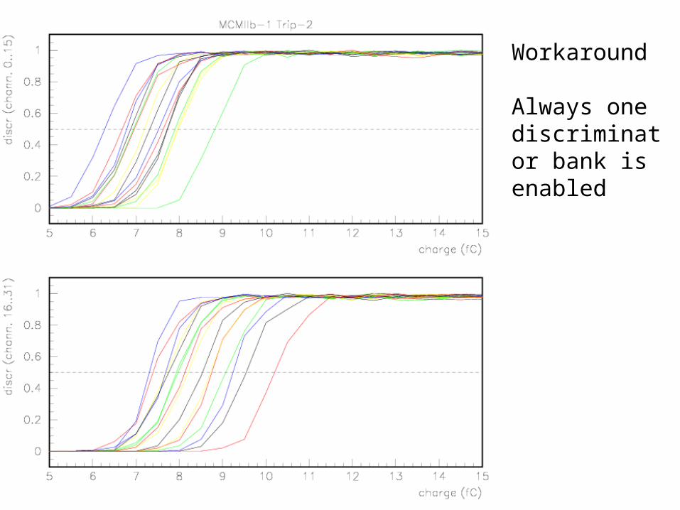
Workaround
Always one discriminator bank is enabled

Design operating Mode, “16 channels swing”.

Design operating Mode, “16 channels swing”.The only difference here is that the “swing” was moved 8 nsec later.
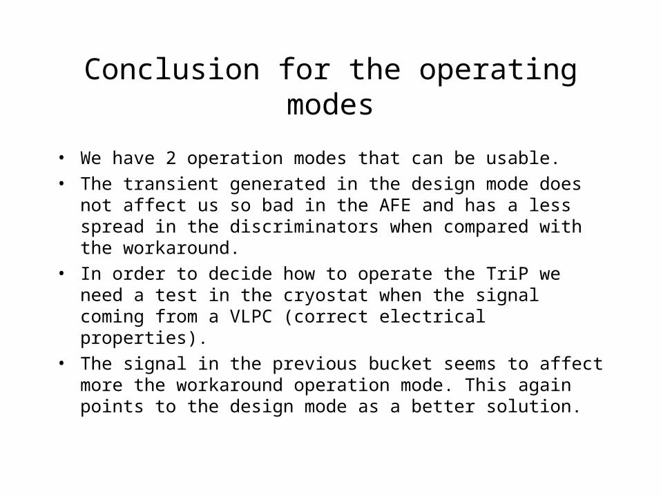
Conclusion for the operating modes
• We have 2 operation modes that can be usable.
• The transient generated in the design mode does not affect us so bad in the AFE and has a less spread in the discriminators when compared with the workaround.
• In order to decide how to operate the TriP we need a test in the cryostat when the signal coming from a VLPC (correct electrical properties).
• The signal in the previous bucket seems to affect more the workaround operation mode. This again points to the design mode as a better solution.

Workaround
Always one discriminator bank is enabled
Significant effect from the previous bucket. (1/25)

Design operating Mode, “16 channels swing”.
No effect from the previous bucket.

We have 2 MCMs with TriP-1 operational, in both we see channel 0 far (3 fC) away of the rest. This is most likely a layout issue in MCMIIb.

Analog Pedestal Spread in Trip-1
Layout?

Analog Pedestal Spread in Trip-2

Timing scan (20 fC input)
For the design operating mode there is full efficiency in a window of 50 nsec. Similar for the other mode.

Conclusions
1. We have to modes to operate the TriP and need to test it in the cryostat with VLPCs to decide which is better.
2. There are some layout issues on the MCMs, we will have to consider this for the final AFEII (useful information)
3. 8 TriPs work from a total of 9 tested!!!!