AF18309 DESIGN GUIDE Threadsure 2threadsure.com.au/.../04/Threadsure-Design-Guide... · It provides...
10
Technical Data Sheets ThreadSURE Concrete Anchor Systems ®
Transcript of AF18309 DESIGN GUIDE Threadsure 2threadsure.com.au/.../04/Threadsure-Design-Guide... · It provides...

Technical Data Sheets
ThreadSUREConcrete Anchor Systems
®

®ThreadSURE Pty Ltd | Ph: 1300 418 218 | www.threadsure.com.au
®The ThreadSURE Connection system is Design protected with AUS DSN NO338779 and AUS DSN NO338512 and Trade Mark protected
Threadsure is an Australian Owned Company formed in 2000. Our aim is to develop
innovative products and systems to aid concrete construction. Since the companies
inception we have provided some of Australia's largest construction / formwork companies
products for installation in high-rise construction, with specialisation in monolithic
structures, hospitals and government buildings.
Get connected!
Threadsure provides a complete service to its clients by offering;
Fully engineered and customised connection systemsŸ
Cost effective productsŸ
Technical and Engineering adviceŸ
Detailed connection drawings, including product quantity take-offs Ÿ
Readily available product lines Ÿ
Quality service from experienced and dedicated construction personnel Ÿ
The development of the ThreadSURE® connection systems has been integral in providing building
solutions, approved by leading Engineers and Building Contractors throughout Australia.
Formworkers and steelfixers recommend our systems for their ease of installation. The systems
provide efficient and superior structural integrity.
Threadsure commissions extensive and ongoing product testing by independent
NATA testing facilities;
Quality control Ÿ
Certification Ÿ
Research and development Ÿ
By fostering long term and ongoing partnerships with manufactures and suppliers alike a quality
product is achieved on each and every occasion.
®ThreadSURE System
®ThreadSURE Concrete Anchor SystemsThreadSUREConcrete Anchor Systems
®
1
Doc. Ref: BW/CG 12-20 | Issued May 2017
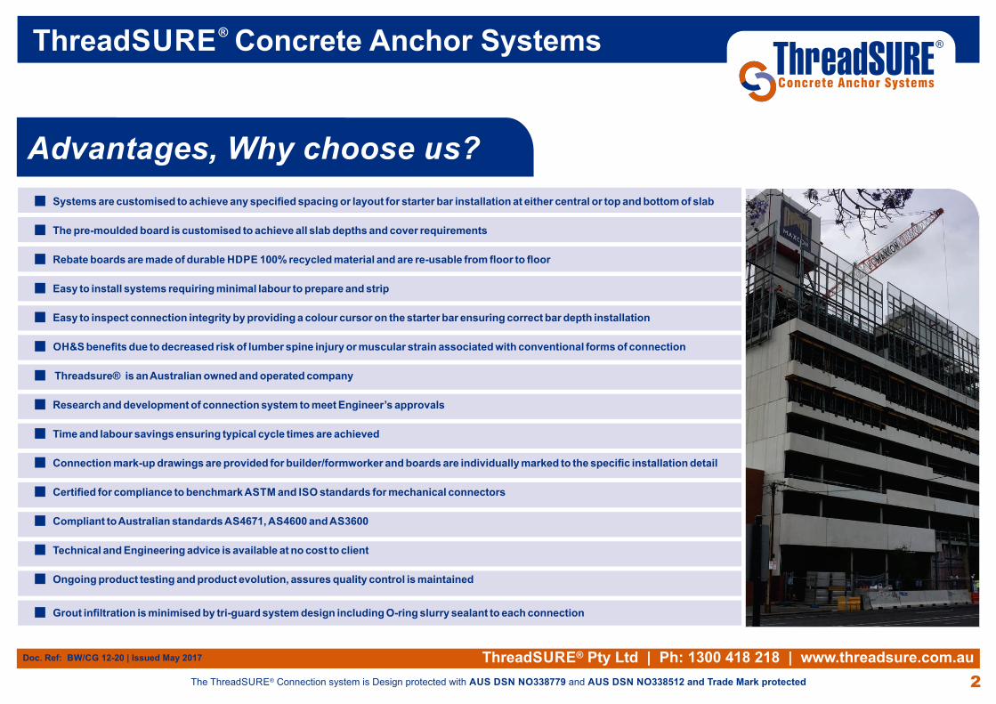
Systems are customised to achieve any specified spacing or layout for starter bar installation at either central or top and bottom of slab n
The pre-moulded board is customised to achieve all slab depths and cover requirements n
Rebate boards are made of durable HDPE 100% recycled material and are re-usable from floor to floorn
Easy to install systems requiring minimal labour to prepare and strip n
Easy to inspect connection integrity by providing a colour cursor on the starter bar ensuring correct bar depth installation n
OH&S benefits due to decreased risk of lumber spine injury or muscular strain associated with conventional forms of connectionn
Threadsure® is an Australian owned and operated companyn
Research and development of connection system to meet Engineer’s approvals n
Time and labour savings ensuring typical cycle times are achievedn
Connection mark-up drawings are provided for builder/formworker and boards are individually marked to the specific installation detailn
Certified for compliance to benchmark ASTM and ISO standards for mechanical connectorsn
Compliant to Australian standards AS4671, AS4600 and AS3600n
Technical and Engineering advice is available at no cost to client n
Ongoing product testing and product evolution, assures quality control is maintained n
Grout infiltration is minimised by tri-guard system design including O-ring slurry sealant to each connection n
®ThreadSURE Pty Ltd | Ph: 1300 418 218 | www.threadsure.com.au
®The ThreadSURE Connection system is Design protected with AUS DSN NO338779 and AUS DSN NO338512 and Trade Mark protected
Advantages, Why choose us?
®ThreadSURE Concrete Anchor Systems
2
ThreadSUREConcrete Anchor Systems
®
Doc. Ref: BW/CG 12-20 | Issued May 2017

THREADSURESYSTEM N16-200 T&BWITH 600 LONG BARS.
®ThreadSURE Pty Ltd | Ph: 1300 418 218 | www.threadsure.com.au
®The ThreadSURE Connection system is Design protected with AUS DSN NO338779 and AUS DSN NO338512 and Trade Mark protected
Slab to core connectionnWall to wall connection nPenetration: Tower crane/concrete npump etc
Where to use? The ThreadSURE® systems are ideal for connection applications including:
®ThreadSURE System
®ThreadSURE Concrete Anchor Systems
3
ThreadSUREConcrete Anchor Systems
®
Stair landing connectionnPrecast element concrete n
connection
THREADSURESYSTEM N16-200 CWITH 650 LONG BARS.
TYPICAL ADJUSTA BAR CONNECTION TO CORE DETAIL (AC1)
CORE CONNECTION TYPE - [A] CORE CONNECTION TYPE - [B] CORE CONNECTION TYPE - [C] CORE CONNECTION TYPE - [G]
CORE CONNECTIONTYPE - [E] - PLAN
Doc. Ref: BW/CG 12-20 | Issued May 2017
THREADSURESYSTEM 12N20 (24 TOTAL)TOP AND BOTTOM 850 LONG.
THREADSUREN24-200 CENTRAL 1050LONG
THREADSURE2 ROWS TOP AND BOTTOMN24-200 WITH 1050 LONGBARS.
4N20 THREADSURE700 MINIMUM LONG INTOSIDE WALL TOP AND BOTTOM(8 TOTAL) 75 COVER.
3N20 THREADSURE850 MINIMUM LONG INTOSIDE WALL TOP AND BOTTOM(6 TOTAL) 75 COVER.
650

ThreadSURE® connection systems
consist of Spherical Graphite Cast Iron
Anchors, a HDPE rebate former board,
500N grade reinforcing starter bars and re-
usable polyurethane board connector
plugs.
Reinforcement Bar – 'TuffBAR'
The TuffBAR features a 500N reinforcing steel bar compliant to AS/NZS 4671.2001 standards and the
systems Ultimate Tensile Strength has been determined from independent NATA Lab mechanical
testing in accordance with AS1381. All bars are epoxy painted with a colour cursor that guarantees full
embedment depth of the starter bar and onsite inspection guarantees every starter bar in installed to its
fullest extent.
ThreadSURE® systems ultimate concrete breakout strength is calculated from the ACI
(American Concrete Institute) method for concrete anchorage strength as specified in section
AS3600.
Rebate Board The HDPE rebate board is customised to the Engineer's specified spacing and starter bar
layout. It consists of a re-cycled material and is resistant to petrochemicals and heat ensuring
its durability and longevity. The length of each board is typically 1.2m in length but can be
adapted at the installer's requests. Each board has three board release half nuts installed to
assist with the stripping of the rebate former after pour.
These are also manufactured from recycled materials and are durable and re-usable from floor
to floor. The O-ring initiative provides a pipe seal around the mouth of the Ferrule during
concrete pour and inhibits any grout/slurry intrusion.
ThreadSURE
®ThreadSURE Pty Ltd | Ph: 1300 418 218 | www.threadsure.com.au
®The ThreadSURE Connection system is Design protected with AUS DSN NO338779 and AUS DSN NO338512 and Trade Mark protected
System and Components
Ferrules
Polyurethane Plug and O-ring Sealer
System available in:
12mm, 16mm, 20mm, 25mm and 32mm
®ThreadSURE Concrete Anchor Systems
4
ThreadSUREConcrete Anchor Systems
®
Doc. Ref: BW/CG 12-20 | Issued May 2017
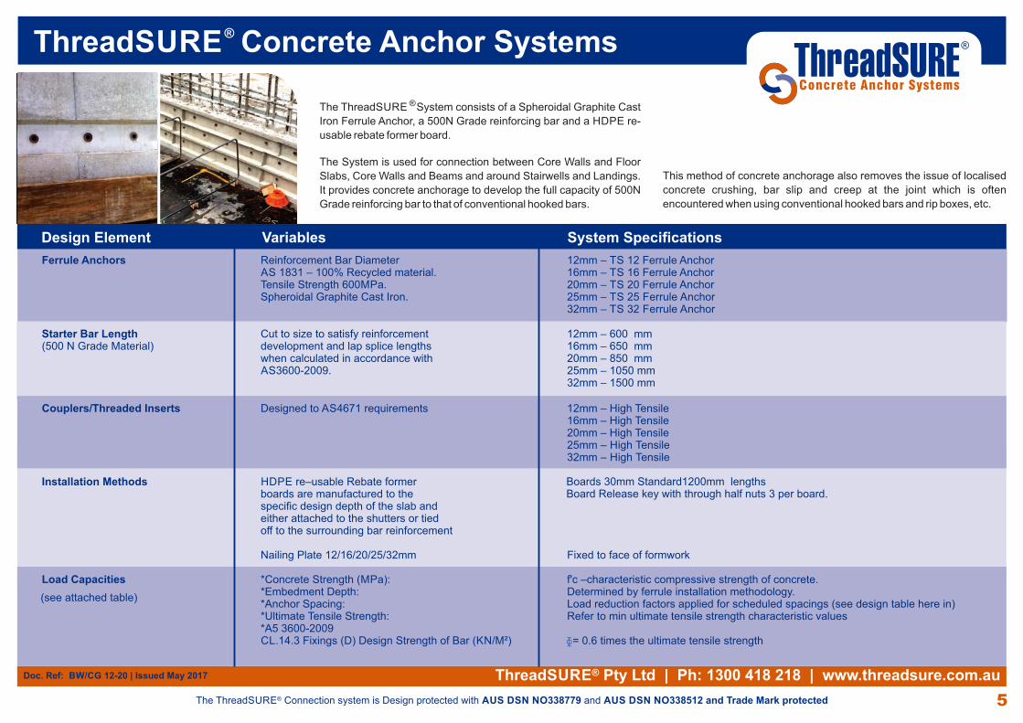
®The ThreadSURE System consists of a Spheroidal Graphite Cast
Iron Ferrule Anchor, a 500N Grade reinforcing bar and a HDPE re-
usable rebate former board.
The System is used for connection between Core Walls and Floor
Slabs, Core Walls and Beams and around Stairwells and Landings.
It provides concrete anchorage to develop the full capacity of 500N
Grade reinforcing bar to that of conventional hooked bars.
Design Element Variables System Specifications
Starter Bar Length Cut to size to satisfy reinforcement 12mm – 600 mm(500 N Grade Material) development and lap splice lengths 16mm – 650 mm when calculated in accordance with 20mm – 850 mm AS3600-2009. 25mm – 1050 mm 32mm – 1500 mm
Couplers/Threaded Inserts Designed to AS4671 requirements 12mm – High Tensile 16mm – High Tensile 20mm – High Tensile 25mm – High Tensile 32mm – High Tensile
Installation Methods HDPE re–usable Rebate former boards are manufactured to the specific design depth of the slab and either attached to the shutters or tied off to the surrounding bar reinforcement Nailing Plate 12/16/20/25/32mm Fixed to face of formwork
Load Capacities *Concrete Strength (MPa): f'c –characteristic compressive strength of concrete. *Embedment Depth: Determined by ferrule installation methodology. *Anchor Spacing: Load reduction factors applied for scheduled spacings (see design table here in) *Ultimate Tensile Strength: Refer to min ultimate tensile strength characteristic values *A5 3600-2009 CL.14.3 Fixings (D) Design Strength of Bar (KN/M²)
Ferrule Anchors Reinforcement Bar Diameter 12mm – TS 12 Ferrule Anchor AS 1831 – 100% Recycled material. 16mm – TS 16 Ferrule Anchor Tensile Strength 600MPa. 20mm – TS 20 Ferrule Anchor Spheroidal Graphite Cast Iron. 25mm – TS 25 Ferrule Anchor 32mm – TS 32 Ferrule Anchor
Boards 30mm Standard1200mm lengths Board Release key with through half nuts 3 per board.
This method of concrete anchorage also removes the issue of localised
concrete crushing, bar slip and creep at the joint which is often
encountered when using conventional hooked bars and rip boxes, etc.
ɸ= 0.6 times the ultimate tensile strength
®ThreadSURE Pty Ltd | Ph: 1300 418 218 | www.threadsure.com.au
®The ThreadSURE Connection system is Design protected with AUS DSN NO338779 and AUS DSN NO338512 and Trade Mark protected
(see attached table)
®ThreadSURE Concrete Anchor Systems
5
ThreadSUREConcrete Anchor Systems
®
Doc. Ref: BW/CG 12-20 | Issued May 2017

®ThreadSURE Concrete Anchor Systems
®ThreadSURE Pty Ltd | Ph: 1300 418 218 | www.threadsure.com.au
®The ThreadSURE Connection system is Design protected with AUS DSN NO338779 and AUS DSN NO338512 and Trade Mark protected 6
Diagonal tensile cracking
Illustration 1. At the ends of the beam a combination of vertical and horizontal shears results in diagonal tensile stresses (see diagram below)
Illustration 2. To prevent this diagonal cracking at the ends of beams or adjacent to any support, it is often necessary to either bend up some of the tensile reinforcement or to use stirrups as indicated below.
�
È ÈLoad
Vertical Shear + Horizontal Shear =
Load
ShearForce
Shear
Shear Diagonaltension
As Consultants and Structural Engineers would understand, shear is a combination of vertical and
horizontal forces as shown in the diagram on the right.
This combination forms a stress block, where the forces or stresses are taken as shown. The
reinforcement in the tensile zone takes the force in tension for the horizontal force, and the concrete
section in the compression zone takes the force in compression for the other horizontal force.
The two vertical forces are carried by the concrete section and vertical reinforcement beams.
There are two fatigue tests for mechanical splices under the ISO standard. The high cycle test if 2 million
cycles designed for structures with moving loads i.e. bridges, car parks etc. The low cycle tests are
designed for two levels of earthquake effect, dependant on location of structure and the likely event of
vibration from such action.
Notes on testing of Threadsure Connector
Shear in Concrete
HC - High Cycle Test
LCI - Low Cycle test to 20 cycles only
LC2 - Low Cycle test to 28 cycles only
HLC1 - Low Cycle test to 20 cycles and high cycle test
HLC2 - Low cycle test to 28 cycles and high cycle test
Based on the testing of the mechanical splices and the results obtained, the Threadsure product is given a
fatigue classification as detailed above as HC as the system is not sold or marketed in zones where LC1,
LC2, HLC1, HLC2 testing is necessary.
D Beal Engineer Pty Ltd
DL Beal, BE, MEngSc, MSc (Lon), DIC, RPEQ, FTE (Aust), APEC Engineer
Concrete Technologist and Designer
Explanation of the ISO Classification
ThreadSUREConcrete Anchor Systems
®
Doc. Ref: BW/CG 12-20 | Issued May 2017

Design Guide
ThreadSUREConcrete Anchor Systems
®
Multiplex Constructions 1 William Project Brisbane

BarArea(Ase)
BarArea(Ase)
BarArea(Ase)
BarCentres
(mm)
BarCentres
(mm)
BarCentres
(mm)
Effective AnchorEmbenment
including HDPE.Rebate FormerBoard (hef mm)
Effective AnchorEmbenment
including HDPE.Rebate FormerBoard (hef mm)
Effective AnchorEmbenment
including HDPE.Rebate FormerBoard (hef mm)
Critical edgedistance for
Load Capacityof Bars(mm) (1.5 x hef)
Critical edgedistance for
Load Capacityof Bars(mm) (1.5 x hef)
Critical edgedistance for
Load Capacityof Bars(mm) (1.5 x hef)
Concretestrength
at28 days(MPa.)
Concretestrength
at28 days(MPa.)
Concretestrength
at28 days(MPa.)
MinimumYield
Strength ofbar (kN)
MinimumYield
Strength ofbar (kN)
MinimumYield
Strength ofbar (kN)
113
201
314
491
804
113
201
314
491
804
113
201
314
491
804
300200150300200150300200150300200150300200150
300200150300200150300200150300200150300200150
300200150300200150300200150300200150300200150
124
151.5
151.5
156
205
124
151.5
151.5
156
205
124
151.5
151.5
156
205
186
227
227
234
307.5
186
227
227
234
307.5
186
227
227
234
307.5
32
32
32
32
32
50
50
50
50
50
65
65
65
65
65
56.5
101
157
245
402
56.5
101
157
245
402
56.5
101
157
245
402
734937805440805440805240916046
9061461016849101684910065501147557
10470531157756115775611475571308665
ReductionFactorfor Bar
Spacing
ReductionFactorfor Bar
Spacing
ReductionFactorfor Bar
Spacing
0.750.500.380.610.410.300.610.410.300.580.380.290.440.290.22
0.750.500.380.610.410.300.610.410.300.580.380.290.440.290.22
0.750.500.380.610.410.300.610.410.300.580.380.290.440.290.22
Ultimate Concrete BreakoutStrength per Anchor (kN).Nb = kc . c . (fc^ 0.5) . (hef^ 1.5)
ACI 318-11 D.5.2.2 - 2011Cast in Anchors
(Uncracked concrete with reduction factor for bar spacing applied)
Ultimate Concrete BreakoutStrength per Anchor (kN).Nb = kc . c . (fc^ 0.5) . (hef^ 1.5)
ACI 318-11 D.5.2.2 - 2011Cast in Anchors
(Uncracked concrete with reduction factor for bar spacing applied)
Ultimate Concrete BreakoutStrength per Anchor (kN).Nb = kc . c . (fc^ 0.5) . (hef^ 1.5)
ACI 318-11 D.5.2.2 - 2011Cast in Anchors
(Uncracked concrete with reduction factor for bar spacing applied)
30mm thick HDPE. Rebate Former Board - Concrete Strength 32 Mpa 30mm thick HDPE. Rebate Former Board - Concrete Strength 50 Mpa
30mm thick HDPE. Rebate Former Board - Concrete Strength 65 Mpa
BarDiameter
(mm)
BarDiameter
(mm)
BarDiameter
(mm)
N12 N12
N12
ReidBar ReidBar
ReidBar
N16 N16
N16
Bar Bar
Bar
N20 N20
N20
Bar Bar
Bar
N25 N25
N25
N32 N32
N32
ReidBar ReidBar
ReidBar
ReidBar ReidBar
ReidBar
®ThreadSURE Concrete Anchor Systems
CASE 1 CASE 3
CASE 4
*NOTE: The above are Ultimate Loads for Reinforcement and Concrete Breakout.For Allowable Design Loads Reduction Factors need to be applied in accordance with ACI 318 - 2011
®ThreadSURE Pty Ltd | Ph: 1300 418 218 | www.threadsure.com.au
®The ThreadSURE Connection system is Design protected with AUS DSN NO338779 and AUS DSN NO338512 and Trade Mark protected
1Doc. Ref: BW/CG 12-20 | Issued May 2017
BarArea(Ase)
BarCentres
(mm)
Effective AnchorEmbenment
including HDPE.Rebate FormerBoard (hef mm)
Critical edgedistance for
Load Capacityof Bars(mm) (1.5 x hef)
Concretestrength
at28 days(MPa.)
MinimumYield
Strength ofbar (kN)
113
201
314
491
804
300200150300200150300200150300200150300200150
124
151.5
151.5
156
205
186
227
227
234
307.5
40
40
40
40
40
56.5
100.6
157
245.5
402
825541906044906044895945
1026751
ReductionFactorfor Bar
Spacing
0.750.500.380.610.410.300.610.410.300.580.380.290.440.290.22
Ultimate Concrete BreakoutStrength per Anchor (kN).Nb = kc . c . (fc^ 0.5) . (hef^ 1.5)
ACI 318-11 D.5.2.2 - 2011Cast in Anchors
(Uncracked concrete with reduction factor for bar spacing applied)
30mm thick HDPE. Rebate Former Board - Concrete Strength 40 Mpa
BarDiameter
(mm)
N12ReidBar
N16Bar
N20Bar
N25
N32
ReidBar
ReidBar
CASE 2
*SEE NOTES BELOW
*SEE NOTES BELOW *SEE NOTES BELOW
*SEE NOTES BELOW

®ThreadSURE Concrete Anchor Systems
*NOTE: The above are Ultimate Loads for Reinforcement and Concrete Breakout.For Allowable Design Loads Reduction Factors need to be applied in accordance with ACI 318 - 2011
®ThreadSURE Pty Ltd | Ph: 1300 418 218 | www.threadsure.com.au
®The ThreadSURE Connection system is Design protected with AUS DSN NO338779 and AUS DSN NO338512 and Trade Mark protected
2Doc. Ref: BW/CG 12-20 | Issued May 2017
The construction applications and details provided in this literature are indicative
only. In every case, project working details and load carrying capacities should
be entrusted to appropriately qualified and experienced persons.
While every care has been exercised in the preparation of this document to
ensure that any advice, recommendations or information is accurate, no liability
or responsibility of any kind is accepted in respect of the use of the Adjusta
Connector System.
All calculations are taken from formulas in ACI-318 2011 and can easily be
verified by engineering consultants. The loads given in these tables are Ultimate
Loads and the appropriate reduction factors for various effects need to be
applied to obtain Safe Working Loads. Situations where combined loads are
applied to the connector should be fully designed on a case by case basis as per
the requirements and examples of ACI-318 2011 to ensure ductile behaviour at
failure.
Structural Engineering Advice