aestro 0 10 immer Sensor Applications - Lutron Electronics · aestro ® 0 10 immer Sensor...
31
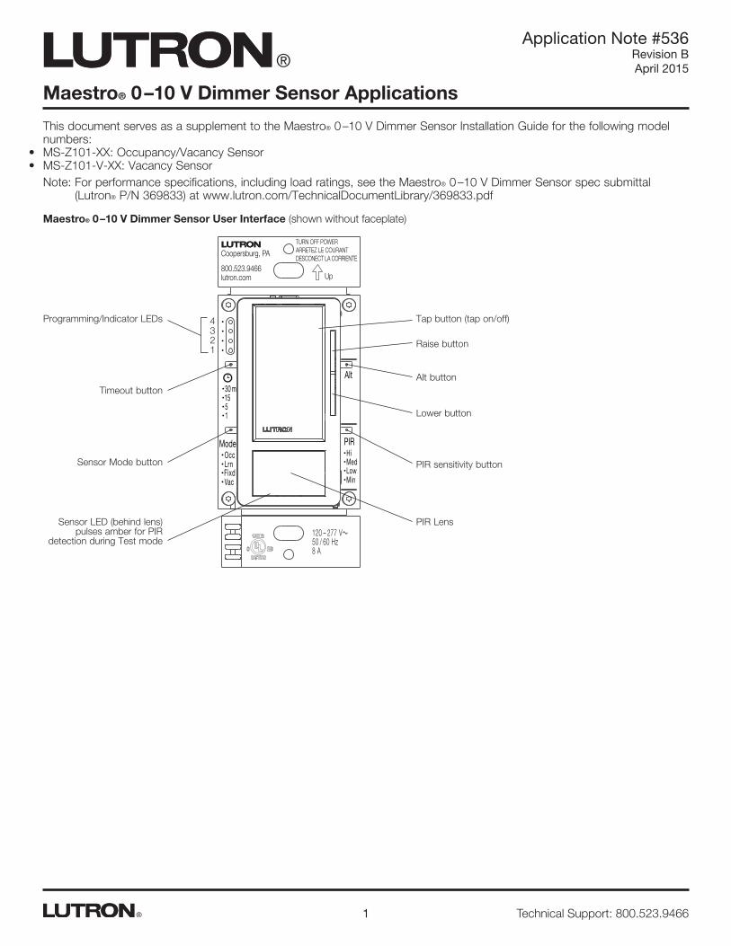
Maestro® 0 –10 V Dimmer Sensor Applications Application Note #536 Revision B April 2015 1 Technical Support: 800.523.9466 ® This document serves as a supplement to the Maestro® 0 –10 V Dimmer Sensor Installation Guide for the following model numbers: • MS-Z101-XX: Occupancy/Vacancy Sensor • MS-Z101-V-XX: Vacancy Sensor Note: For performance specifications, including load ratings, see the Maestro® 0 –10 V Dimmer Sensor spec submittal (Lutron® P/N 369833) at www.lutron.com/TechnicalDocumentLibrary/369833.pdf Maestro® 0 –10 V Dimmer Sensor User Interface (shown without faceplate) Tap button (tap on/off) Programming/Indicator LEDs Timeout button PIR sensitivity button Sensor Mode button Sensor LED (behind lens) pulses amber for PIR detection during Test mode PIR Lens m 30 15 5 1 Occ Lrn Fixd Vac Mode Hi Med Low Min PIR 120 – 277 V~ 50 / 60 Hz 8 A Alt TURN OFF POWER ARRETEZ LE COURANT DESCONECT LA CORRIENTE Up Coopersburg, PA 800.523.9466 lutron.com 4 3 2 1 Raise button Alt button Lower button
Transcript of aestro 0 10 immer Sensor Applications - Lutron Electronics · aestro ® 0 10 immer Sensor...
Maestro® 0 –10 V Dimmer Sensor Applications
Application Note #536Revision BApril 2015
1 Technical Support: 800.523.9466®
This document serves as a supplement to the Maestro® 0 –10 V Dimmer Sensor Installation Guide for the following model numbers:
• MS-Z101-XX: Occupancy/Vacancy Sensor• MS-Z101-V-XX: Vacancy Sensor
Note: For performance specifications, including load ratings, see the Maestro® 0 –10 V Dimmer Sensor spec submittal (Lutron® P/N 369833) at www.lutron.com/TechnicalDocumentLibrary/369833.pdf
Maestro® 0 –10 V Dimmer Sensor User Interface (shown without faceplate)
Tap button (tap on/off)Programming/Indicator LEDs
Timeout button
PIR sensitivity buttonSensor Mode button
Sensor LED (behind lens) pulses amber for PIR
detection during Test mode
PIR Lens
m301551
OccLrnFixdVac
ModeHiMedLowMin
PIR
120 – 277 V~50 / 60 Hz 8 A
Alt
TURN OFF POWERARRETEZ LE COURANTDESCONECT LA CORRIENTE Up
Coopersburg, PA
800.523.9466lutron.com
4 3 2 1
Raise button
Alt button
Lower button
2
Application Note #536
www.lutron.com®
ContentsGlossary . . . . . . . . . . . . . . . . . . . . . . . . . . . . . . . . . . . . . . . . . . . . . . . . . . . . . . . . . . . . . . . . . . . . . . . . . . . . . . . . . . . . . . . . 3
Sensor Coverage Area . . . . . . . . . . . . . . . . . . . . . . . . . . . . . . . . . . . . . . . . . . . . . . . . . . . . . . . . . . . . . . . . . . . . . . . . . . . . . 4
Settings Overview . . . . . . . . . . . . . . . . . . . . . . . . . . . . . . . . . . . . . . . . . . . . . . . . . . . . . . . . . . . . . . . . . . . . . . . . . . . . . . . . . 5
Fade-to-On Rate . . . . . . . . . . . . . . . . . . . . . . . . . . . . . . . . . . . . . . . . . . . . . . . . . . . . . . . . . . . . . . . . . . . . . . . . . . . . . . . . . 6
Fade-to-Off Rate . . . . . . . . . . . . . . . . . . . . . . . . . . . . . . . . . . . . . . . . . . . . . . . . . . . . . . . . . . . . . . . . . . . . . . . . . . . . . . . . . 7
High-End Trim . . . . . . . . . . . . . . . . . . . . . . . . . . . . . . . . . . . . . . . . . . . . . . . . . . . . . . . . . . . . . . . . . . . . . . . . . . . . . . . . . . . 8
Low-End Trim . . . . . . . . . . . . . . . . . . . . . . . . . . . . . . . . . . . . . . . . . . . . . . . . . . . . . . . . . . . . . . . . . . . . . . . . . . . . . . . . . . . . 9
Occupied Level . . . . . . . . . . . . . . . . . . . . . . . . . . . . . . . . . . . . . . . . . . . . . . . . . . . . . . . . . . . . . . . . . . . . . . . . . . . . . . . . . . 10
Preset Level . . . . . . . . . . . . . . . . . . . . . . . . . . . . . . . . . . . . . . . . . . . . . . . . . . . . . . . . . . . . . . . . . . . . . . . . . . . . . . . . . . . . 11
Off-While-Occupied . . . . . . . . . . . . . . . . . . . . . . . . . . . . . . . . . . . . . . . . . . . . . . . . . . . . . . . . . . . . . . . . . . . . . . . . . . . . . . 12
PIR Sensitivity . . . . . . . . . . . . . . . . . . . . . . . . . . . . . . . . . . . . . . . . . . . . . . . . . . . . . . . . . . . . . . . . . . . . . . . . . . . . . . . . . . . 13
Selectable Dimming Curve . . . . . . . . . . . . . . . . . . . . . . . . . . . . . . . . . . . . . . . . . . . . . . . . . . . . . . . . . . . . . . . . . . . . . . . . . 14
Timeout . . . . . . . . . . . . . . . . . . . . . . . . . . . . . . . . . . . . . . . . . . . . . . . . . . . . . . . . . . . . . . . . . . . . . . . . . . . . . . . . . . . . . . . 15
Walk-Thru Mode . . . . . . . . . . . . . . . . . . . . . . . . . . . . . . . . . . . . . . . . . . . . . . . . . . . . . . . . . . . . . . . . . . . . . . . . . . . . . . . . 16
Sensor Mode . . . . . . . . . . . . . . . . . . . . . . . . . . . . . . . . . . . . . . . . . . . . . . . . . . . . . . . . . . . . . . . . . . . . . . . . . . . . . . . . . . . 17
Fixed ALD Light Level . . . . . . . . . . . . . . . . . . . . . . . . . . . . . . . . . . . . . . . . . . . . . . . . . . . . . . . . . . . . . . . . . . . . . . . . . . . . . 18
Learning Ambient Light Detect (ALD) . . . . . . . . . . . . . . . . . . . . . . . . . . . . . . . . . . . . . . . . . . . . . . . . . . . . . . . . . . . . . . . . . 19
Test Mode . . . . . . . . . . . . . . . . . . . . . . . . . . . . . . . . . . . . . . . . . . . . . . . . . . . . . . . . . . . . . . . . . . . . . . . . . . . . . . . . . . . . . 20
Default Settings . . . . . . . . . . . . . . . . . . . . . . . . . . . . . . . . . . . . . . . . . . . . . . . . . . . . . . . . . . . . . . . . . . . . . . . . . . . . . . . . . 20
Wiring Installations with the Maestro® 0 – 10 V Dimmer Sensor . . . . . . . . . . . . . . . . . . . . . . . . . . . . . . . . . . . . . . . . . . . . . . 21
Single-Pole Installation . . . . . . . . . . . . . . . . . . . . . . . . . . . . . . . . . . . . . . . . . . . . . . . . . . . . . . . . . . . . . . . . . . . . . . . . 21
3-Way Installation with Standard Mechanical Switch . . . . . . . . . . . . . . . . . . . . . . . . . . . . . . . . . . . . . . . . . . . . . . . . . 22
3-Way Retrofit Installation . . . . . . . . . . . . . . . . . . . . . . . . . . . . . . . . . . . . . . . . . . . . . . . . . . . . . . . . . . . . . . . . . . . . . . 23
120 V~ Multi-Location Installation with Maestro® Accessory Switches. . . . . . . . . . . . . . . . . . . . . . . . . . . . . . . . . . . . 24
220 – 277 V~ Multi-Location Installation with Maestro® Accessory Switches . . . . . . . . . . . . . . . . . . . . . . . . . . . . . . . 25
Common Applications and Questions. . . . . . . . . . . . . . . . . . . . . . . . . . . . . . . . . . . . . . . . . . . . . . . . . . . . . . . . . . . . . 26
Energy Codes Requiring Daylighting . . . . . . . . . . . . . . . . . . . . . . . . . . . . . . . . . . . . . . . . . . . . . . . . . . . . . . . . . . . . . . 27
NEMA 410 Inrush Current . . . . . . . . . . . . . . . . . . . . . . . . . . . . . . . . . . . . . . . . . . . . . . . . . . . . . . . . . . . . . . . . . . . . . . . . . . 28
Troubleshooting . . . . . . . . . . . . . . . . . . . . . . . . . . . . . . . . . . . . . . . . . . . . . . . . . . . . . . . . . . . . . . . . . . . . . . . . . . . . . . . . . 29
Contact Information . . . . . . . . . . . . . . . . . . . . . . . . . . . . . . . . . . . . . . . . . . . . . . . . . . . . . . . . . . . . . . . . . . . . . . . . . . . . . . 31
3
Application Note #536
www.lutron.com®
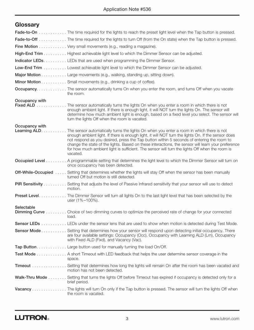
GlossaryFade-to-On . . . . . . . . . . . . The time required for the lights to reach the preset light level when the Tap button is pressed.
Fade-to-Off . . . . . . . . . . . . The time required for the lights to turn Off (from the On state) when the Tap button is pressed.
Fine Motion . . . . . . . . . . . . Very small movements (e.g., reading a magazine).
High-End Trim . . . . . . . . . . Highest achievable light level to which the Dimmer Sensor can be adjusted.
Indicator LEDs . . . . . . . . . . LEDs that are used when programming the Dimmer Sensor.
Low-End Trim . . . . . . . . . . Lowest achievable light level to which the Dimmer Sensor can be adjusted.
Major Motion . . . . . . . . . . . Large movements (e.g., walking, standing up, sitting down).
Minor Motion . . . . . . . . . . . Small movements (e.g., drinking a cup of coffee).
Occupancy. . . . . . . . . . . . . The sensor automatically turns On when you enter the room, and turns Off when you vacate the room.
Occupancy withFixed ALD . . . . . . . . . . . . . The sensor automatically turns the lights On when you enter a room in which there is not
enough ambient light. If there is enough light, it will NOT turn the lights On. The sensor will determine how much ambient light is enough, based on a fixed level you select. The sensor will turn the lights Off when the room is vacated.
Occupancy withLearning ALD . . . . . . . . . . . The sensor automatically turns the lights On when you enter a room in which there is not
enough ambient light. If there is enough light, it will NOT turn the lights On. If the sensor does not respond as you desired, press the Tap button within 5 seconds of entering the room to change the state of the lights. Based on these interactions, the sensor will learn your preference for how much ambient light is sufficient. The sensor will turn the lights Off when the room is vacated.
Occupied Level . . . . . . . . . A programmable setting that determines the light level to which the Dimmer Sensor will turn on once occupancy has been detected.
Off-While-Occupied . . . . . Setting that determines whether the lights will stay Off when the sensor has been manually turned Off but motion is still detected.
PIR Sensitivity . . . . . . . . . . Setting that adjusts the level of Passive Infrared sensitivity that your sensor will use to detect motion.
Preset Level . . . . . . . . . . . . The Dimmer Sensor will turn all lights On to the last light level that has been selected by the user (1% –100%).
Selectable Dimming Curve . . . . . . . . . Choice of two dimming curves to optimize the perceived rate of change for your connected
load.
Sensor LEDs . . . . . . . . . . . LEDs under the sensor lens that are used to show when motion is detected during Test Mode.
Sensor Mode . . . . . . . . . . . Setting that determines how your sensor will respond upon detecting initial occupancy. There are four available settings: Occupancy (Occ), Occupancy with Learning ALD (Lrn), Occupancy with Fixed ALD (Fixd), and Vacancy (Vac).
Tap Button . . . . . . . . . . . . . Large button used for manually turning the load On/Off.
Test Mode . . . . . . . . . . . . . A short Timeout with LED feedback that helps the user determine sensor coverage in the space.
Timeout . . . . . . . . . . . . . . . Setting that determines how long the lights will remain On after the room has been vacated and motion has not been detected.
Walk-Thru Mode . . . . . . . . Setting that turns the lights Off before Timeout has expired if occupancy is detected only for a brief period.
Vacancy . . . . . . . . . . . . . . . The lights will turn On only if the Tap button is pressed. The sensor will turn the lights Off when the room is vacated.

4
Application Note #536
www.lutron.com®
Sensor Coverage Area• The ability of the Dimmer Sensor to detect motion requires line-of-sight of room occupants. The Dimmer Sensor must have
an unobstructed view of the room.• Hot objects and moving air currents can affect the performance of the Dimmer Sensor. For best performance, the Dimmer
Sensor should be mounted at least 4 ft (1.2 m) away from HVAC vents and light bulbs.• The performance of the Dimmer Sensor depends on a temperature differential between the ambient room temperature and
that of room occupants. Warmer rooms may reduce the ability of the Dimmer Sensor to detect occupants.
Horizontal Beam Diagram(For Reference Only)
15 ft (4.5 m)
10 ft (3 m)
5 ft (1.5 m)
0
5 ft (1.5 m)
10 ft (3 m)
15 ft (4.5 m)
Test room dimensions: 37 ft × 38 ft (11.28 m × 11.6 m)Test floor surface material: CarpetSensor coverage angle: 180°
NEMA WD7 Test Grid Coverage
Major motion coverage: 900 ft2 (81 m2)
Minor motion coverage: 400 ft2 (36 m2)
15 ft (4.5 m)
10 ft (3 m)
5 ft (1.5 m)
0
5 ft (1.5 m)
10 ft (3 m)
15 ft (4.5 m)
0 5 ft 10 ft 15 ft 20 ft 25 ft 30 ft (1.5 m) (3 m) (4.5 m) (6 m) (7.5 m) (9m)
Vertical Beam Diagram(For Reference Only)
0 10 ft 20 ft 30 ft (3 m) (6 m) (9m)
4 ft (1.2 m)
5
Application Note #536
www.lutron.com®
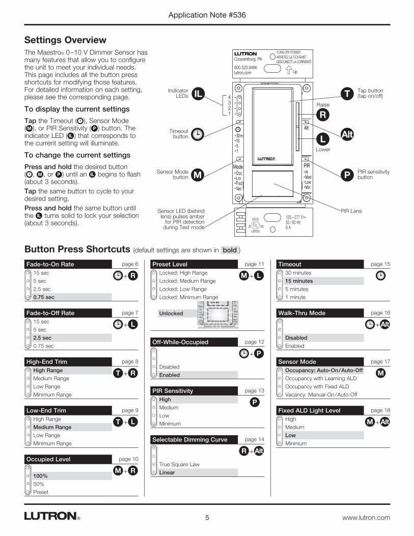
Settings OverviewThe Maestro® 0 –10 V Dimmer Sensor has many features that allow you to configure the unit to meet your individual needs. This page includes all the button press shortcuts for modifying those features. For detailed information on each setting, please see the corresponding page.
To display the current settings
Tap the Timeout ( ), Sensor Mode ( M ), or PIR Sensitivity ( P ) button. The indicator LED ( IL ) that corresponds to the current setting will illuminate.
To change the current settings
Press and hold the desired button ( , M , or P ) until an IL begins to flash (about 3 seconds).Tap the same button to cycle to your desired setting.Press and hold the same button until the IL turns solid to lock your selection (about 3 seconds).
Tap button (tap on/off)
Indicator LEDs
Timeout button
PIR sensitivity button
Sensor Mode button
Sensor LED (behind lens) pulses amber
for PIR detection during Test mode
PIR Lens
m301551
OccLrnFixdVac
ModeHiMedLowMin
PIR
120 – 277 V~50 / 60 Hz 8 A
Alt
TURN OFF POWERARRETEZ LE COURANTDESCONECT LA CORRIENTE Up
Coopersburg, PA
800.523.9466lutron.com
4 3 2 1
IL
M
Raise
Lower
L
R
T
Alt
P
Fade-to-On Rate page 6
15 sec
5 sec
2.5 sec
0.75 sec
R+
Occupied Level page 10
100%
50%
Preset
RM +
Sensor Mode page 17
Occupancy: Auto-On / Auto-Off
Occupancy with Learning ALD
Occupancy with Fixed ALD
Vacancy: Manual-On / Auto-Off
M
Fade-to-Off Rate page 7
15 sec
5 sec
2.5 sec
0.75 sec
L+
Off-While-Occupied page 12
Disabled
Enabled
P+
Fixed ALD Light Level page 18
High
Medium
Low
Minimum
AltM +
High-End Trim page 8
High Range
Medium Range
Low Range
Minimum Range
RT +
PIR Sensitivity page 13
High
Medium
Low
Minimum
P
Timeout page 15
30 minutes
15 minutes
5 minutes
1 minute
Low-End Trim page 9
High Range
Medium Range
Low Range
Minimum Range
LT +
Selectable Dimming Curve page 14
True Square Law
Linear
AltR +
Walk-Thru Mode page 16
Disabled
Enabled
Alt+
Button Press Shortcuts (default settings are shown in bold )
Preset Level page 11
Locked: High Range
Locked: Medium Range
Locked: Low Range
Locked: Minimum Range
Unlocked
LM +
m301551
OccLrnFixdVac
ModeHiMedLowMin
PIR
120 – 277 V~50 / 60 Hz 8 A
Alt
TURN OFF POWERARRETEZ LE COURANTDESCONECT LA CORRIENTE Up
Coopersburg, PA
800.523.9466lutron.com
c
6
Application Note #536
www.lutron.com®
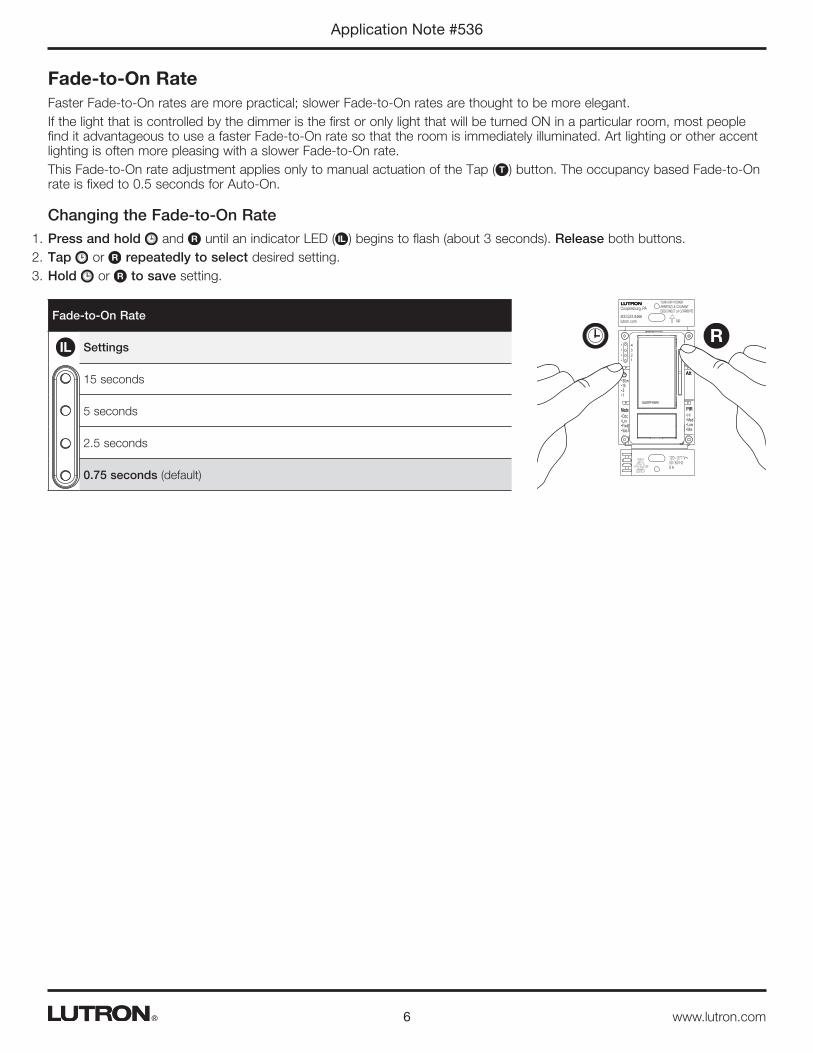
Fade-to-On RateFaster Fade-to-On rates are more practical; slower Fade-to-On rates are thought to be more elegant.If the light that is controlled by the dimmer is the first or only light that will be turned ON in a particular room, most people find it advantageous to use a faster Fade-to-On rate so that the room is immediately illuminated. Art lighting or other accent lighting is often more pleasing with a slower Fade-to-On rate.This Fade-to-On rate adjustment applies only to manual actuation of the Tap ( T ) button. The occupancy based Fade-to-On rate is fixed to 0.5 seconds for Auto-On.
Changing the Fade-to-On Rate1. Press and hold and R until an indicator LED ( IL ) begins to flash (about 3 seconds). Release both buttons.2. Tap or R repeatedly to select desired setting.3. Hold or R to save setting.
Fade-to-On Rate
Settings
15 seconds
5 seconds
2.5 seconds
0.75 seconds (default)
IL
m301551
OccLrnFixdVac
ModeHiMedLowMin
PIR
120 – 277 V~50 / 60 Hz 8 A
Alt
TURN OFF POWERARRETEZ LE COURANTDESCONECT LA CORRIENTE Up
Coopersburg, PA
800.523.9466lutron.com
4
3
2
1
R

7
Application Note #536
www.lutron.com®
Fade-to-Off RateA slower Fade-to-Off rate is suggested for rooms where the user wishes to leave while the lights are still providing illumination. Please be aware that dimming of the light may not be immediately noticeable for settings of 5 seconds or longer.This Fade-to-Off rate adjustment applies only to manual actuation of the Tap ( T ) button. The occupancy based Fade-to-Off rate is fixed to 10 seconds for Auto-Off.
Changing the Fade-to-Off Rate1. Press and hold and L until an indicator LED ( IL ) begins to blink or flash (about 3 seconds).2. Tap or L repeatedly to select desired setting.3. Hold or L to save setting.
Fade-to-Off Rate
Settings
15 seconds
5 seconds
2.5 seconds (default)
0.75 seconds
IL
m301551
OccLrnFixdVac
ModeHiMedLowMin
PIR
120 – 277 V~50 / 60 Hz 8 A
Alt
TURN OFF POWERARRETEZ LE COURANTDESCONECT LA CORRIENTE Up
Coopersburg, PA
800.523.9466lutron.com
4
3
2
1
L

8
Application Note #536
www.lutron.com®
High-End TrimHigh-end trim is adjustable from 6 –10.5 V. The maximum light output of connected fixtures can be decreased for energy savings in over-lit spaces.
Changing the High-End Trim1. Press and hold T and R until the PIR lens flashes (about 7 seconds).2. Press and hold R until the #4 indicator light ( IL ) is reached and the lights dim up no further.3. Hold L until the desired light level is achieved.4. Single tap T to save setting.
High-End Trim
Settings
High range (default)
Medium range
Low range
Minimum range
IL
m301551
OccLrnFixdVac
ModeHiMedLowMin
PIR
120 – 277 V~50 / 60 Hz 8 A
Alt
TURN OFF POWERARRETEZ LE COURANTDESCONECT LA CORRIENTE Up
Coopersburg, PA
800.523.9466lutron.com
4
3
2
1
T R

9
Application Note #536
www.lutron.com®
Low-End TrimLow-end trim is adjustable from 0.6 – 2 V. Trimmable low-end can ensure a stable light level. Some fixtures will flicker or drop out if trimmed too low.
Changing the Low-End Trim1. Press and hold T and L until the PIR lens flashes (about 7 seconds).2. Press and hold L until the #1 indicator light ( IL ) is reached and the lights dim down no further.3. Hold R until all bulbs are on and stable (no flickering) or an otherwise desired light level is achieved.4. Single tap T to save setting.
Low-End Trim
Settings
High range
Medium range (default)
Low range
Minimum range
IL
m301551
OccLrnFixdVac
ModeHiMedLowMin
PIR
120 – 277 V~50 / 60 Hz 8 A
Alt
TURN OFF POWERARRETEZ LE COURANTDESCONECT LA CORRIENTE Up
Coopersburg, PA
800.523.9466lutron.com
4
3
2
1
T L
10
Application Note #536
www.lutron.com®
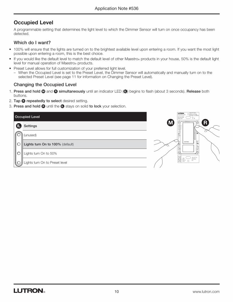
Occupied LevelA programmable setting that determines the light level to which the Dimmer Sensor will turn on once occupancy has been detected.
Which do I want?• 100% will ensure that the lights are turned on to the brightest available level upon entering a room. If you want the most light
possible upon entering a room, this is the best choice.• If you would like the default level to match the default level of other Maestro® products in your house, 50% is the default light
level for manual operation of Maestro® products.• Preset Level allows for full customization of your preferred light level.
– When the Occupied Level is set to the Preset Level, the Dimmer Sensor will automatically and manually turn on to the selected Preset Level (see page 11 for information on Changing the Preset Level).
Changing the Occupied Level1. Press and hold M and R simultaneously until an indicator LED ( IL ) begins to flash (about 3 seconds). Release both
buttons.2. Tap R repeatedly to select desired setting.3. Press and hold R until the IL stays on solid to lock your selection.
Occupied Level
Settings
(unused)
Lights turn On to 100% (default)
Lights turn On to 50%
Lights turn On to Preset level
IL
m301551
OccLrnFixdVac
ModeHiMedLowMin
PIR
120 – 277 V~50 / 60 Hz 8 A
Alt
TURN OFF POWERARRETEZ LE COURANTDESCONECT LA CORRIENTE Up
Coopersburg, PA
800.523.9466lutron.com
4
3
2
1
M R
11
Application Note #536
www.lutron.com®
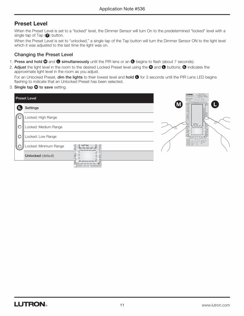
Preset LevelWhen the Preset Level is set to a “locked” level, the Dimmer Sensor will turn On to the predetermined “locked” level with a single tap of Tap ( T ) button.When the Preset Level is set to “unlocked,” a single tap of the Tap button will turn the Dimmer Sensor ON to the light level which it was adjusted to the last time the light was on.
Changing the Preset Level1. Press and hold M and L simultaneously until the PIR lens or an IL begins to flash (about 7 seconds).2. Adjust the light level in the room to the desired Locked Preset level using the R and L buttons; IL indicates the
approximate light level in the room as you adjust.For an Unlocked Preset, dim the lights to their lowest level and hold L for 3 seconds until the PIR Lens LED begins flashing to indicate that an Unlocked Preset has been selected.
3. Single tap M to save setting.
Preset Level
Settings
Locked: High Range
Locked: Medium Range
Locked: Low Range
Locked: Minimum Range
Unlocked (default)
IL
m301551
OccLrnFixdVac
ModeHiMedLowMin
PIR
120 – 277 V~50 / 60 Hz 8 A
Alt
TURN OFF POWERARRETEZ LE COURANTDESCONECT LA CORRIENTE Up
Coopersburg, PA
800.523.9466lutron.com
c
m301551
OccLrnFixdVac
ModeHiMedLowMin
PIR
120 – 277 V~50 / 60 Hz 8 A
Alt
TURN OFF POWERARRETEZ LE COURANTDESCONECT LA CORRIENTE Up
Coopersburg, PA
800.523.9466lutron.com
c
M L
12
Application Note #536
www.lutron.com®
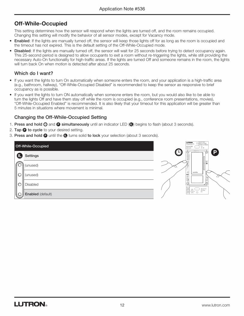
Off-While-OccupiedThis setting determines how the sensor will respond when the lights are turned off, and the room remains occupied. Changing this setting will modify the behavior of all sensor modes, except for Vacancy mode.
• Enabled: If the lights are manually turned off, the sensor will keep those lights off for as long as the room is occupied and the timeout has not expired. This is the default setting of the Off-While-Occupied mode.
• Disabled: If the lights are manually turned off, the sensor will wait for 25 seconds before trying to detect occupancy again. This 25-second period is designed to allow occupants to exit a room without re-triggering the lights, while still providing the necessary Auto-On functionality for high-traffic areas. If the lights are turned Off and someone remains in the room, the lights will turn back On when motion is detected after about 25 seconds.
Which do I want?• If you want the lights to turn On automatically when someone enters the room, and your application is a high-traffic area
(e.g., bathroom, hallway), “Off-While-Occupied Disabled” is recommended to keep the sensor as responsive to brief occupancy as is possible.
• If you want the lights to turn ON automatically when someone enters the room, but you would also like to be able to turn the lights Off and have them stay off while the room is occupied (e.g., conference room presentations, movies), “Off-While-Occupied Enabled” is recommended. It is also likely that your timeout for this application will be greater than 5 minutes in situations where movement is minimal.
Changing the Off-While-Occupied Setting1. Press and hold and P simultaneously until an indicator LED ( IL ) begins to flash (about 3 seconds).2. Tap P to cycle to your desired setting.3. Press and hold P until the IL turns solid to lock your selection (about 3 seconds).
Off-While-Occupied
Settings
(unused)
(unused)
Disabled
Enabled (default)
IL
m301551
OccLrnFixdVac
ModeHiMedLowMin
PIR
120 – 277 V~50 / 60 Hz 8 A
Alt
TURN OFF POWERARRETEZ LE COURANTDESCONECT LA CORRIENTE Up
Coopersburg, PA
800.523.9466lutron.com
4
3
2
1
P
13
Application Note #536
www.lutron.com®
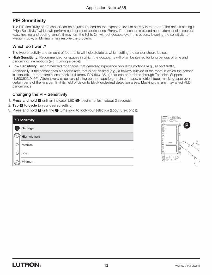
PIR SensitivityThe PIR sensitivity of the sensor can be adjusted based on the expected level of activity in the room. The default setting is “High Sensitivity” which will perform best for most applications. Rarely, if the sensor is placed near external noise sources (e.g., heating and cooling vents), it may turn the lights On without occupancy. If this occurs, lowering the sensitivity to Medium, Low, or Minimum may resolve the problem.
Which do I want?The type of activity and amount of foot traffic will help dictate at which setting the sensor should be set.
• High Sensitivity: Recommended for spaces in which the occupants will often be seated for long periods of time and performing fine motions (e.g., turning a page).
• Low Sensitivity: Recommended for spaces that generally experience only large motions (e.g., as foot traffic).Additionally, if the sensor sees a specific area that is not desired (e.g., a hallway outside of the room in which the sensor is installed), Lutron offers a lens mask kit (Lutron® P/N 50013614) that can be ordered through Technical Support (1.800.523.9466). Alternatively, selectively placing opaque tape (e.g., painters’ tape, electrical tape, masking tape) over certain parts of the lens can limit its field of vision to block undesired detection areas. Masking the lens may affect ALD performance.
Changing the PIR Sensitivity1. Press and hold P until an indicator LED ( IL ) begins to flash (about 3 seconds).2. Tap P to cycle to your desired setting.3. Press and hold P until the IL turns solid to lock your selection (about 3 seconds).
PIR Sensitivity
Settings
High (default)
Medium
Low
Minimum
IL
m301551
OccLrnFixdVac
ModeHiMedLowMin
PIR
120 – 277 V~50 / 60 Hz 8 A
Alt
TURN OFF POWERARRETEZ LE COURANTDESCONECT LA CORRIENTE Up
Coopersburg, PA
800.523.9466lutron.com
4
3
2
1
P
14
Application Note #536
www.lutron.com®
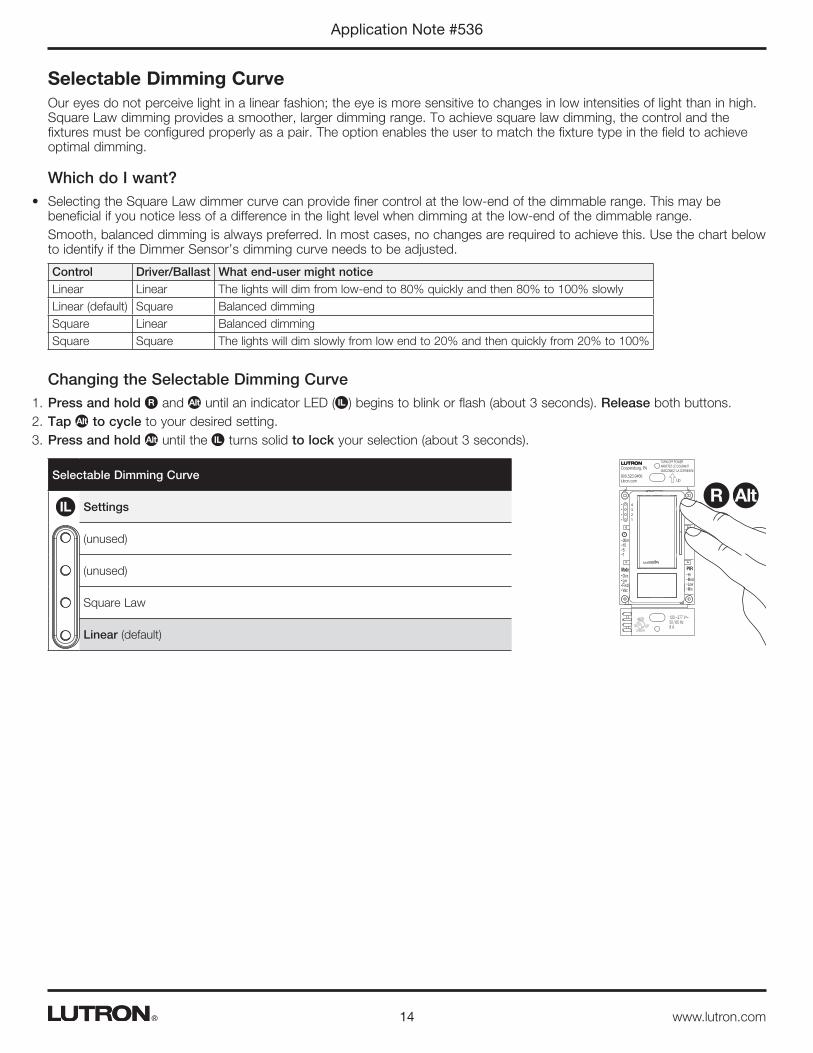
Selectable Dimming CurveOur eyes do not perceive light in a linear fashion; the eye is more sensitive to changes in low intensities of light than in high. Square Law dimming provides a smoother, larger dimming range. To achieve square law dimming, the control and the fixtures must be configured properly as a pair. The option enables the user to match the fixture type in the field to achieve optimal dimming.
Which do I want?• Selecting the Square Law dimmer curve can provide finer control at the low-end of the dimmable range. This may be
beneficial if you notice less of a difference in the light level when dimming at the low-end of the dimmable range.Smooth, balanced dimming is always preferred. In most cases, no changes are required to achieve this. Use the chart below to identify if the Dimmer Sensor’s dimming curve needs to be adjusted.
Control Driver/Ballast What end-user might noticeLinear Linear The lights will dim from low-end to 80% quickly and then 80% to 100% slowlyLinear (default) Square Balanced dimmingSquare Linear Balanced dimmingSquare Square The lights will dim slowly from low end to 20% and then quickly from 20% to 100%
Changing the Selectable Dimming Curve1. Press and hold R and Alt until an indicator LED ( IL ) begins to blink or flash (about 3 seconds). Release both buttons.2. Tap Alt to cycle to your desired setting.3. Press and hold Alt until the IL turns solid to lock your selection (about 3 seconds).
Selectable Dimming Curve
Settings
(unused)
(unused)
Square Law
Linear (default)
IL
m301551
OccLrnFixdVac
ModeHiMedLowMin
PIR
120 – 277 V~50 / 60 Hz 8 A
Alt
TURN OFF POWERARRETEZ LE COURANTDESCONECT LA CORRIENTE Up
Coopersburg, PA
800.523.9466lutron.com
4
3
2
1
AltR
15
Application Note #536
www.lutron.com®
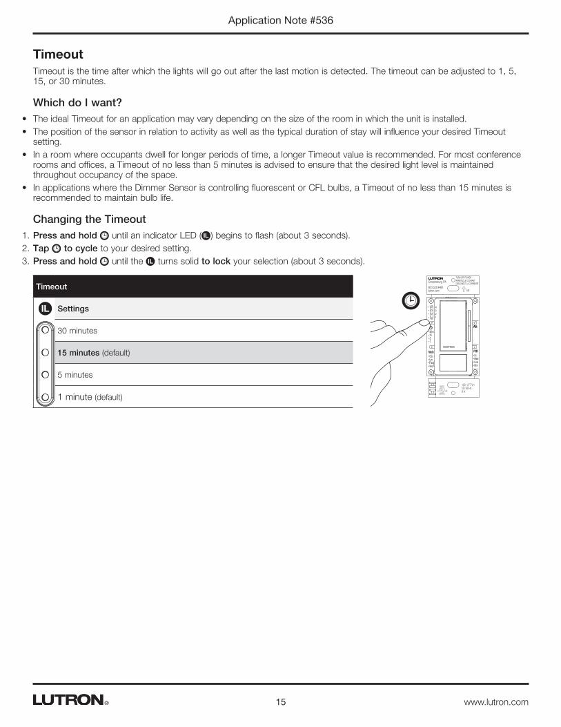
TimeoutTimeout is the time after which the lights will go out after the last motion is detected. The timeout can be adjusted to 1, 5, 15, or 30 minutes.
Which do I want?• The ideal Timeout for an application may vary depending on the size of the room in which the unit is installed.• The position of the sensor in relation to activity as well as the typical duration of stay will influence your desired Timeout
setting.• In a room where occupants dwell for longer periods of time, a longer Timeout value is recommended. For most conference
rooms and offices, a Timeout of no less than 5 minutes is advised to ensure that the desired light level is maintained throughout occupancy of the space.
• In applications where the Dimmer Sensor is controlling fluorescent or CFL bulbs, a Timeout of no less than 15 minutes is recommended to maintain bulb life.
Changing the Timeout1. Press and hold until an indicator LED ( IL ) begins to flash (about 3 seconds).2. Tap to cycle to your desired setting.3. Press and hold until the IL turns solid to lock your selection (about 3 seconds).
Timeout
Settings
30 minutes
15 minutes (default)
5 minutes
1 minute (default)
IL
m301551
OccLrnFixdVac
ModeHiMedLowMin
PIR
120 – 277 V~50 / 60 Hz 8 A
Alt
TURN OFF POWERARRETEZ LE COURANTDESCONECT LA CORRIENTE Up
Coopersburg, PA
800.523.9466lutron.com
4
3
2
1

16
Application Note #536
www.lutron.com®
Notes:• To maintain bulb life, the recommended minimum timeout for fluorescent bulbs is 15 minutes. Walk-Thru Mode is not
recommended for applications with CFL or fluorescent lights.• If Walk-Thru Mode is enabled, that setting will override a 1-minute timeout setting if that setting is also selected. The lights
will remain On for a minimum of 3 minutes if Walk-Thru Mode is enabled.
Walk-Thru ModeWalk-Thru Mode is a setting that allows lights set with a long timeout to shut off after a short duration when the space is occupied only momentarily. After initial occupancy, this mode allows the sensor to turn the lights in the room Off if the space is occupied for a very brief amount of time (less than 3 minutes). If motion is detected consistently within 3 minutes of initial occupancy, the sensor will keep the lights On for the normal timeout setting.
• Walk-Thru Mode Enabled: If the space is occupied momentarily, the lights will turn off after 3 minutes instead of the normal timeout setting.
• Walk-Thru Mode Disabled: The lights will always remain On for the full timeout duration.
Which do I want?• If you would like the lights in your space to turn off quickly when the space is only briefly occupied, select “Enabled”. This
setting is ideal for conference rooms with long timeouts that may experience periodic brief occupancy events, such as a second-shift cleaning crew or a security guard checking the campus of a commercial building.
• If you prefer consistent sensor behavior or use CFL or fluorescent lights in your application, Walk-Thru Mode should be “Disabled”.
Changing the Walk-Thru Mode1. Press and hold and Alt until the indicator LED ( IL ) begins to flash.2. The Walk-Thru Mode setting will now be displayed on the IL . Tap Alt to cycle to your desired setting.3. Press and hold Alt until the IL turns solid to lock your selection (about 3 seconds).
Walk-Thru Mode
Settings
(unused)
(unused)
Walk-Thru Mode Disabled (default)
Walk-Thru Mode Enabled
IL
m301551
OccLrnFixdVac
ModeHiMedLowMin
PIR
120 – 277 V~50 / 60 Hz 8 A
Alt
TURN OFF POWERARRETEZ LE COURANTDESCONECT LA CORRIENTE Up
Coopersburg, PA
800.523.9466lutron.com
4
3
2
1
Alt
17
Application Note #536
www.lutron.com®
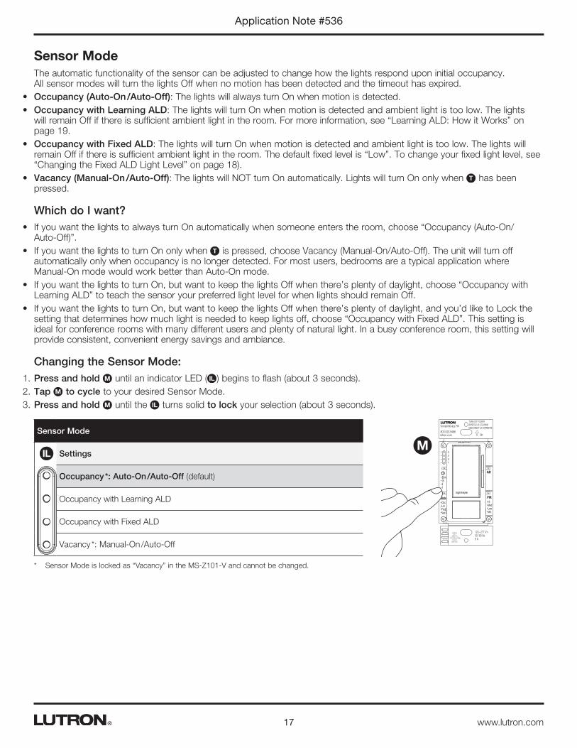
Sensor ModeThe automatic functionality of the sensor can be adjusted to change how the lights respond upon initial occupancy. All sensor modes will turn the lights Off when no motion has been detected and the timeout has expired.
• Occupancy (Auto-On /Auto-Off): The lights will always turn On when motion is detected.• Occupancy with Learning ALD: The lights will turn On when motion is detected and ambient light is too low. The lights
will remain Off if there is sufficient ambient light in the room. For more information, see “Learning ALD: How it Works” on page 19.
• Occupancy with Fixed ALD: The lights will turn On when motion is detected and ambient light is too low. The lights will remain Off if there is sufficient ambient light in the room. The default fixed level is “Low”. To change your fixed light level, see “Changing the Fixed ALD Light Level” on page 18).
• Vacancy (Manual-On /Auto-Off): The lights will NOT turn On automatically. Lights will turn On only when T has been pressed.
Which do I want?• If you want the lights to always turn On automatically when someone enters the room, choose “Occupancy (Auto-On/
Auto-Off)”.• If you want the lights to turn On only when T is pressed, choose Vacancy (Manual-On/Auto-Off). The unit will turn off
automatically only when occupancy is no longer detected. For most users, bedrooms are a typical application where Manual-On mode would work better than Auto-On mode.
• If you want the lights to turn On, but want to keep the lights Off when there’s plenty of daylight, choose “Occupancy with Learning ALD” to teach the sensor your preferred light level for when lights should remain Off.
• If you want the lights to turn On, but want to keep the lights Off when there’s plenty of daylight, and you’d like to Lock the setting that determines how much light is needed to keep lights off, choose “Occupancy with Fixed ALD”. This setting is ideal for conference rooms with many different users and plenty of natural light. In a busy conference room, this setting will provide consistent, convenient energy savings and ambiance.
Changing the Sensor Mode:1. Press and hold M until an indicator LED ( IL ) begins to flash (about 3 seconds).2. Tap M to cycle to your desired Sensor Mode.3. Press and hold M until the IL turns solid to lock your selection (about 3 seconds).
Sensor Mode
Settings
Occupancy *: Auto-On /Auto-Off (default)
Occupancy with Learning ALD
Occupancy with Fixed ALD
Vacancy *: Manual-On /Auto-Off
* Sensor Mode is locked as “Vacancy” in the MS-Z101-V and cannot be changed.
IL
m301551
OccLrnFixdVac
ModeHiMedLowMin
PIR
120 – 277 V~50 / 60 Hz 8 A
Alt
TURN OFF POWERARRETEZ LE COURANTDESCONECT LA CORRIENTE Up
Coopersburg, PA
800.523.9466lutron.com
4
3
2
1
M
18
Application Note #536
www.lutron.com®
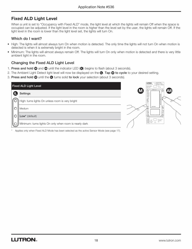
Fixed ALD Light LevelWhen a unit is set to “Occupancy with Fixed ALD” mode, the light level at which the lights will remain Off when the space is occupied can be adjusted. If the light level in the room is higher than the level set by the user, the lights will remain Off. If the light level in the room is lower than the light level set, the lights will turn On.
Which do I want?• High: The lights will almost always turn On when motion is detected. The only time the lights will not turn On when motion is
detected is when it is extremely bright in the room.• Minimum: The lights will almost always remain Off. The lights will turn On only when motion is detected and there is very little
ambient light in the room.
Changing the Fixed ALD Light Level1. Press and hold M and Alt until the indicator LED ( IL ) begins to flash (about 3 seconds).2. The Ambient Light Detect light level will now be displayed on the IL . Tap M to cycle to your desired setting.3. Press and hold M until the IL turns solid to lock your selection (about 3 seconds).
Fixed ALD Light Level
Settings
High: turns lights On unless room is very bright
Medium
Low* (default)
Minimum: turns lights On only when room is nearly dark
* Applies only when Fixed ALD Mode has been selected as the active Sensor Mode (see page 17).
IL
m301551
OccLrnFixdVac
ModeHiMedLowMin
PIR
120 – 277 V~50 / 60 Hz 8 A
Alt
TURN OFF POWERARRETEZ LE COURANTDESCONECT LA CORRIENTE Up
Coopersburg, PA
800.523.9466lutron.com
4
3
2
1
M Alt
19
Application Note #536
www.lutron.com®
Learning Ambient Light Detect (ALD)How it WorksAmbient Light Detect (ALD) is a feature that allows you to maximize savings by keeping lights Off when there is enough natural light in a space to fulfill your lighting requirements.The Lutron® Learning ALD feature learns your preference as you live with the product in your space. The learning algorithm employs user inputs to determine when ambient light is sufficient.
Will my sensor use Learning ALD?Your sensor will use Learning ALD if you’ve selected “Occupancy with Learning ALD” (Lrn) mode while programming your unit.
How does the sensor learn my preference?Whenever you enter a room with a Dimmer Sensor using the Learning ALD feature, the sensor will either turn the lights On or keep the lights Off, based on its current ALD light level threshold. If you enter the room and the lights do not respond as you’d like, press the T button on your unit to turn the lights On (or Off, if that was your preference) within 5 seconds of entering the room. The sensor will now begin learning your preferred ALD threshold. It may take multiple interactions for the sensor’s adjustments to match your preferred ALD threshold. Here is an example to illustrate the learning process:
1. You enter the room and the lights stay Off, but you decide you want the lights On because there is not enough ambient light in the space.
2. You press the T button (within 5 seconds of entering the room).
3. The unit has learned from this, and has begun to adjust its ALD light threshold towards your preference.
FAQsIf I press a button AFTER 5 seconds of being in a room, will my unit “learn” that preference?No, you must interact within the first 5 seconds of entering the room.
How many times do I have to interact with the sensor to get it to remember my settings?The sensor typically learns the appropriate threshold within 6 –10 consistent interactions.
I’m using the Learning ALD feature, but when I enter the room and turn the lights Off, they turn back On. What’s happening?If you have “Off-While-Occupied” set to “Disabled”, you may experience the lights turning back On while in ALD mode if you turn the lights Off and continue to occupy the space. This means that the sensor is getting closer to your preferred light level, but has not learned it yet. After a few more interactions with the unit, the lights will stay Off at the desired light level, even if the space remains occupied.
I believe I’m using Learning ALD correctly, but I’m still not getting the response I expect. What could be happening?– You may have multiple users with widely different
preferences. If multiple users continue to “teach” the unit separate preferences, it will continue to try to adjust to meet the threshold, but may be stuck somewhere in between the preferences of the two users. Consider using “Occupancy with Fixed ALD” at one of the four light level thresholds.
– You may not be able to reach your unit within 5 seconds. If your interactions do not happen within 5 seconds, you may not be teaching the unit a new threshold. This lack of interaction may be reinforcing the current threshold (because the sensor thinks you like the current setting).
Many people use the room in which the sensor is located. How can I “lock” an ALD light level so it doesn’t change daily?Use the “Occupancy with Fixed ALD” feature. The Fixed ALD light level threshold you choose will not change based on user interactions.

20
Application Note #536
www.lutron.com®
Default SettingsThe Dimmer Sensor has the ability to be returned to its original default settings. This ability allows the programmer a risk-free experience to try multiple setting configurations.
Restoring Default SettingsPress and hold Alt and P until all IL s blink slowly (about 7 seconds). This will restore ALL of the settings back to the default settings.
Default settings
Fade-to-On Rate . . . . . . . . . . . . . . . 0.75 seconds
Fade-to-Off Rate . . . . . . . . . . . . . . . 2.5 seconds
Fixed ALD Light Level . . . . . . . . . . . . Low
High-End Trim . . . . . . . . . . . . . . . . High range
Low-End Trim. . . . . . . . . . . . . . . . . Medium range
Occupied Level . . . . . . . . . . . . . . . . 100%
Off-While-Occupied. . . . . . . . . . . . . . Off-While-Occupied Enabled
PIR Sensitivity . . . . . . . . . . . . . . . . High
Preset Level . . . . . . . . . . . . . . . . . Unlocked
Timeout. . . . . . . . . . . . . . . . . . . . 15 minutes
Selectable Dimming Curve . . . . . . . . . . Linear
Sensor Mode . . . . . . . . . . . . . . . . . Occupancy (Auto-ON /Auto-OFF)
Walk-Thru Mode . . . . . . . . . . . . . . . Walk-Thru Mode Disabled
Note: After restoring the default settings, the Dimmer Sensor will reset. This will take about 10 seconds. During this time, the Dimmer Sensor will not respond to motion or button presses.
Test ModeTest Mode is a short timeout (less than 15 seconds) that will test the coverage area of the sensor with the current settings.
Enabling Test Mode1. Press and hold T until the PIR lens flashes (about 7 seconds).2. The device will exit Test Mode automatically after 5 minutes of inactivity, or when
T is pressed.Notes:
• An amber sensor LED flashes to indicate PIR detection. If no motion is detected for the entire duration of the shorter Timeout (15 seconds), the load(s) being controlled by the Dimmer Sensor will turn Off. The load(s) will turn back On when motion is detected.
• If Test Mode is entered within 2 minutes of power-up, sensor LED will blink twice quickly and repeat every 2 seconds until the sensor is ready.
m301551
OccLrnFixdVac
ModeHiMedLowMin
PIR
120 – 277 V~50 / 60 Hz 8 A
Alt
TURN OFF POWERARRETEZ LE COURANTDESCONECT LA CORRIENTE Up
Coopersburg, PA
800.523.9466lutron.com
4
3
2
1
T
m301551
OccLrnFixdVac
ModeHiMedLowMin
PIR
120 – 277 V~50 / 60 Hz 8 A
Alt
TURN OFF POWERARRETEZ LE COURANTDESCONECT LA CORRIENTE Up
Coopersburg, PA
800.523.9466lutron.com
4
3
2
1
PAlt
21
Application Note #536
www.lutron.com®
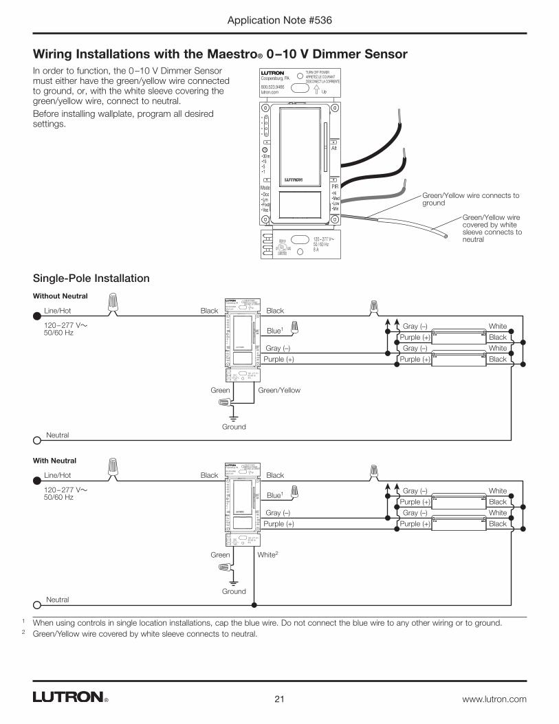
Wiring Installations with the Maestro® 0 – 10 V Dimmer SensorIn order to function, the 0 –10 V Dimmer Sensor must either have the green/yellow wire connected to ground, or, with the white sleeve covering the green/yellow wire, connect to neutral.Before installing wallplate, program all desired settings.
Single-Pole Installation
Green/Yellow wire connects to ground
Green/Yellow wire covered by white sleeve connects to neutral
m301551
OccLrnFixdVac
ModeHiMedLowMin
PIR
120 – 277 V~50 / 60 Hz 8 A
Alt
TURN OFF POWERARRETEZ LE COURANTDESCONECT LA CORRIENTE Up
Coopersburg, PA
800.523.9466lutron.com
1 When using controls in single location installations, cap the blue wire. Do not connect the blue wire to any other wiring or to ground.2 Green/Yellow wire covered by white sleeve connects to neutral.
m301551
OccLrnFixdVac
ModeHiMedLowMin
PIR
120 – 277 V~ 50 / 60 Hz 8 A
Alt
TURN OFF POWERARRETEZ LE COURANTDESCONECT LA CORRIENTE Up
Coopersburg, PA
800.523.9466lutron.com
Purple (+)
Purple (+)
Purple (+)
Gray (–)
Gray (–)
Gray (–)
Ground
Green Green/Yellow
Black Black
Black
Black
White
White
Neutral
Line/Hot
Blue1120 – 277 V~ 50/60 Hz
Without Neutral
m301551
OccLrnFixdVac
ModeHiMedLowMin
PIR
120 – 277 V~ 50 / 60 Hz 8 A
Alt
TURN OFF POWERARRETEZ LE COURANTDESCONECT LA CORRIENTE Up
Coopersburg, PA
800.523.9466lutron.com
Purple (+)
Purple (+)
Purple (+)
Gray (–)
Gray (–)
Gray (–)
Ground
Green
Black Black
Black
Black
White
White
Neutral
Line/Hot
Blue1120 – 277 V~ 50/60 Hz
White2
With Neutral
22
Application Note #536
www.lutron.com®
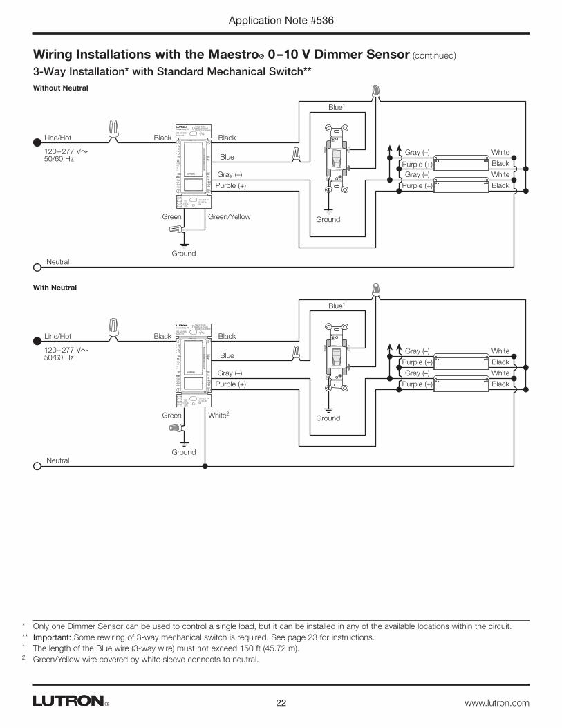
Wiring Installations with the Maestro® 0 – 10 V Dimmer Sensor (continued)
3-Way Installation* with Standard Mechanical Switch**
* Only one Dimmer Sensor can be used to control a single load, but it can be installed in any of the available locations within the circuit.** Important: Some rewiring of 3-way mechanical switch is required. See page 23 for instructions.1 The length of the Blue wire (3-way wire) must not exceed 150 ft (45.72 m).2 Green/Yellow wire covered by white sleeve connects to neutral.
m301551
OccLrnFixdVac
ModeHiMedLowMin
PIR
120 – 277 V~ 50 / 60 Hz 8 A
Alt
TURN OFF POWERARRETEZ LE COURANTDESCONECT LA CORRIENTE Up
Coopersburg, PA
800.523.9466lutron.com
Purple (+)
Purple (+)
Purple (+)
Gray (–)
Gray (–)
Gray (–)
Ground
GroundGreen Green/Yellow
Black Black
Black
Black
White
White
Neutral
Line/Hot
Blue
Blue1
120 – 277 V~ 50/60 Hz
Without Neutral
m301551
OccLrnFixdVac
ModeHiMedLowMin
PIR
120 – 277 V~ 50 / 60 Hz 8 A
Alt
TURN OFF POWERARRETEZ LE COURANTDESCONECT LA CORRIENTE Up
Coopersburg, PA
800.523.9466lutron.com
Blue1
Purple (+)
Purple (+)
Purple (+)
Gray (–)
Gray (–)
Gray (–)
Ground
GroundGreen
Black Black
Black
Black
White
White
Neutral
Blue
Line/Hot
120 – 277 V~ 50/60 Hz
White2
With Neutral
23
Application Note #536
www.lutron.com®
Wiring Installations with the Maestro® 0 – 10 V Dimmer Sensor (continued)
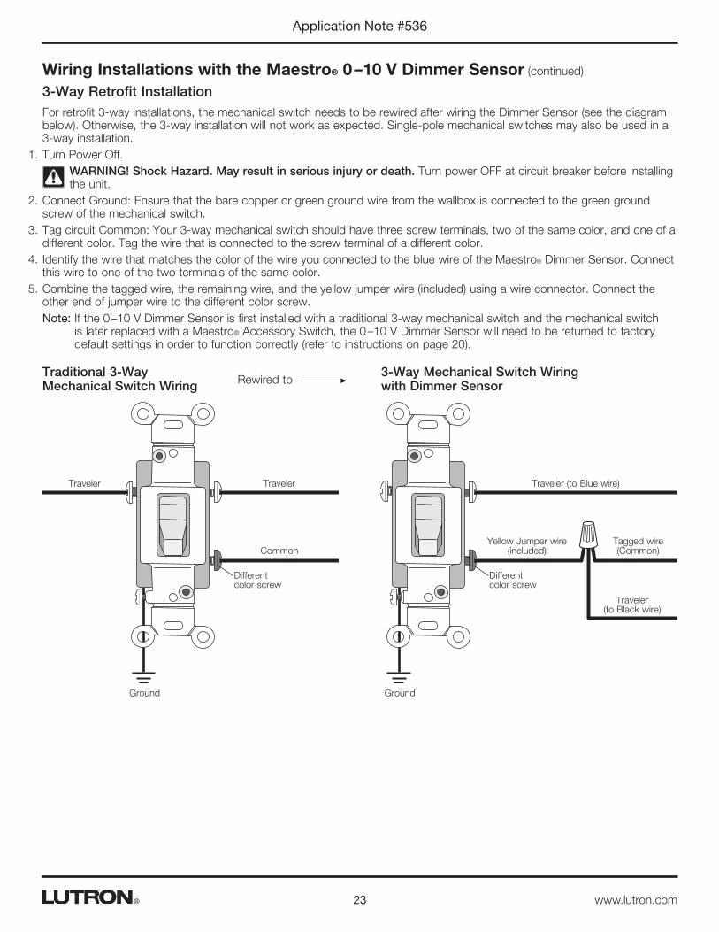
3-Way Retrofit InstallationFor retrofit 3-way installations, the mechanical switch needs to be rewired after wiring the Dimmer Sensor (see the diagram below). Otherwise, the 3-way installation will not work as expected. Single-pole mechanical switches may also be used in a 3-way installation.
1. Turn Power Off.WARNING! Shock Hazard. May result in serious injury or death. Turn power OFF at circuit breaker before installing the unit.
2. Connect Ground: Ensure that the bare copper or green ground wire from the wallbox is connected to the green ground screw of the mechanical switch.
3. Tag circuit Common: Your 3-way mechanical switch should have three screw terminals, two of the same color, and one of a different color. Tag the wire that is connected to the screw terminal of a different color.
4. Identify the wire that matches the color of the wire you connected to the blue wire of the Maestro® Dimmer Sensor. Connect this wire to one of the two terminals of the same color.
5. Combine the tagged wire, the remaining wire, and the yellow jumper wire (included) using a wire connector. Connect the other end of jumper wire to the different color screw.Note: If the 0 –10 V Dimmer Sensor is first installed with a traditional 3-way mechanical switch and the mechanical switch
is later replaced with a Maestro® Accessory Switch, the 0 –10 V Dimmer Sensor will need to be returned to factory default settings in order to function correctly (refer to instructions on page 20).
3-Way Mechanical Switch Wiring with Dimmer Sensor
Yellow Jumper wire (included)
Tagged wire (Common)
Ground
Traveler (to Blue wire)
Traveler (to Black wire)
Different color screw
Traditional 3-Way Mechanical Switch Wiring
Common
Ground
TravelerTraveler
Different color screw
Rewired to
24
Application Note #536
www.lutron.com®
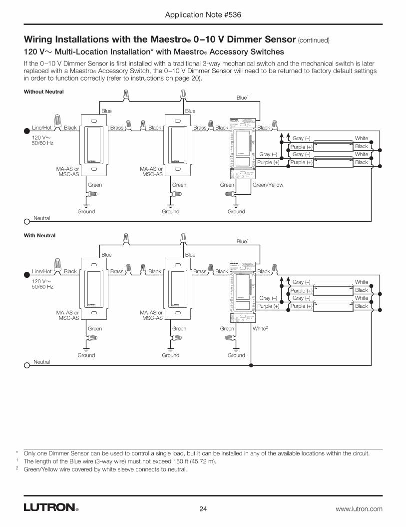
Wiring Installations with the Maestro® 0 – 10 V Dimmer Sensor (continued)
120 V~ Multi-Location Installation* with Maestro® Accessory Switches If the 0 –10 V Dimmer Sensor is first installed with a traditional 3-way mechanical switch and the mechanical switch is later replaced with a Maestro® Accessory Switch, the 0 –10 V Dimmer Sensor will need to be returned to factory default settings in order to function correctly (refer to instructions on page 20).
m301551
OccLrnFixdVac
ModeHiMedLowMin
PIR
120 – 277 V~ 50 / 60 Hz 8 A
Alt
TURN OFF POWERARRETEZ LE COURANTDESCONECT LA CORRIENTE Up
Coopersburg, PA
800.523.9466lutron.com
Purple (+)
Purple (+)
Purple (+)
Gray (–)
Gray (–)
Gray (–)
Brass Brass
Ground Ground Ground
Green Green Green Green/Yellow
Black Black Black Black
Black
Black
White
White
Neutral
Line/Hot
Blue Blue
Blue1
120 V~ 50/60 Hz
MA-AS or MSC-AS
MA-AS or MSC-AS
Without Neutral
m301551
OccLrnFixdVac
ModeHiMedLowMin
PIR
120 – 277 V~ 50 / 60 Hz 8 A
Alt
TURN OFF POWERARRETEZ LE COURANTDESCONECT LA CORRIENTE Up
Coopersburg, PA
800.523.9466lutron.com
Purple (+)
Purple (+)
Purple (+)
Gray (–)
Gray (–)
Gray (–)
Brass Brass
Ground Ground Ground
Green Green Green
Black Black Black Black
Black
Black
White
White
Neutral
Line/Hot
Blue Blue
Blue1
120 V~ 50/60 Hz
MA-AS or MSC-AS
MA-AS or MSC-AS
White2
With Neutral
* Only one Dimmer Sensor can be used to control a single load, but it can be installed in any of the available locations within the circuit.1 The length of the Blue wire (3-way wire) must not exceed 150 ft (45.72 m).2 Green/Yellow wire covered by white sleeve connects to neutral.

25
Application Note #536
www.lutron.com®
Wiring Installations with the Maestro® 0 – 10 V Dimmer Sensor (continued)
220 – 277 V~ Multi-Location Installation with Maestro® Accessory Switches If the 0 –10 V Dimmer Sensor is first installed with a traditional 3-way mechanical switch and the mechanical switch is later replaced with a Maestro® Accessory Switch, the 0 –10 V Dimmer Sensor will need to be returned to factory default settings in order to function correctly (refer to instructions on page 20).
m301551
OccLrnFixdVac
ModeHiMedLowMin
PIR
120 – 277 V~ 50 / 60 Hz 8 A
Alt
TURN OFF POWERARRETEZ LE COURANTDESCONECT LA CORRIENTE Up
Coopersburg, PA
800.523.9466lutron.com
Purple (+)
Purple (+)
Purple (+)
Gray (–)
Gray (–)
Gray (–)
Red Red
Ground Ground Ground
Green Green Green Green/Yellow
Black Black Black Black
Black
Black
White
White
Neutral
Line/Hot
Blue Blue
Blue1
220 – 277 V~ 50/60 Hz
MA-AS-277 or MSC-AS-277
MA-AS-277 or MSC-AS-277
Without Neutral
m301551
OccLrnFixdVac
ModeHiMedLowMin
PIR
120 – 277 V~ 50 / 60 Hz 8 A
Alt
TURN OFF POWERARRETEZ LE COURANTDESCONECT LA CORRIENTE Up
Coopersburg, PA
800.523.9466lutron.com
Purple (+)
Purple (+)
Purple (+)
Gray (–)
Gray (–)
Gray (–)
Red Red
Ground Ground Ground
Green Green Green
Black Black Black Black
Black
Black
White
White
Neutral
Line/Hot
Blue Blue
Blue1
220 – 277 V~ 50/60 Hz
MA-AS-277 or MSC-AS-277
MA-AS-277 or MSC-AS-277
White2
With Neutral
* Only one Dimmer Sensor can be used to control a single load, but it can be installed in any of the available locations within the circuit.1 The length of the Blue wire (3-way wire) must not exceed 150 ft (45.72 m).2 Green/Yellow wire covered by white sleeve connects to neutral.

26
Application Note #536
www.lutron.com®
Wiring Installations with the Maestro® 0 – 10 V Dimmer Sensor (continued)
Common Applications and Questions
Sink vs. Source
MS-Z101 is a “sink-only” device (see www.lutron.com/TechnicalDocumentLibrary/048442.pdf for more information). This type of device requires the ballast or driver to supply the power necessary to drive the 0 –10 V- control wires. MS-Z101 works with all ballasts and drivers that provide a 0 –10 V- control signal that is compliant with IEC 60629 Annex E.2. Note that some LED drivers are sink-only (they require the lighting control to provide the power to drive the 0 –10 V- control wires). These will be incompatible with MS-Z101 alone. See below for methods to control sink-only fixtures.
Miswire and incompatible loadAlertThe user will receive a visual alert when the product’s 0 –10 V- control wires (gray and purple) are incorrectly connected or when an incompatible load—one that is not compliant with IEC 60629 Annex E.2—is detected. The product will still function as a switch in these instances.
• Approximately 9 seconds after initial power-up, the PIR lens will flash 3 times. Approximately 2 seconds after that, the lens will flash 3 additional times, indicating that the device has detected an error in the 0 –10 V- wiring.
• During operation, the product will disable the fade rate so that the device will essentially function only as a switch. If the user presses the Raise or Lower button, the lens will flash 3 times and no dimming will occur. This will happen every time Raise/Lower is pressed until the miswiring is corrected or a compatible load is connected.
SolutionTo provide an occupancy sensor solution for drivers or ballasts that require power from the control (not compliant with IEC 60629 Annex E.2):
• Use a Radio Powr SavrTM occupancy sensor and a 0 –10 V- PowPak® module (e.g., LRF2-OCR2B-P and RMJ-5T-DV-B). See www.lutron.com/en-US/Products/Pages/SingleRoomControls/Energi_TriPak/Overview.aspx for more information.
• Use a plug-in supply to supply power to the 0 –10 V- control wires. See www.lutron.com/TechnicalDocumentLibrary/048442.pdf. Lutron® model number GRX-15VDC-330-CPN6058 has a 10 mA capacity, with the capability to operate a minimum of 5 ballasts (drivers) if they are compliant with ESTA E1.3. Note that this requires 120 V~ to be available as the power source for the GRX-15VDC-330-CPN6058.
m301551
OccLrnFixdVac
ModeHiMedLowMin
PIR
120 – 277 V~ 50 / 60 Hz 8 A
Alt
TURN OFF POWERARRETEZ LE COURANTDESCONECT LA CORRIENTE Up
Coopersburg, PA
800.523.9466lutron.com
Purple (+)
Purple (+)
Purple (+)
Gray (–)
Gray (–)
Gray (–)
Ground
Green Green/Yellow
Black Black
Black
Black
White
White
Neutral
Line/Hot
Blue1120 – 277 V~ 50/60 Hz
+–
GRX-15VDC-330-CPN6058
m301551
OccLrnFixdVac
ModeHiMedLowMin
PIR
120 – 277 V~50 / 60 Hz 8 A
Alt
TURN OFF POWERARRETEZ LE COURANTDESCONECT LA CORRIENTE Up
Coopersburg, PA
800.523.9466lutron.com
c
1 When using controls in single location installations, cap the blue wire. Do not connect the blue wire to any other wiring or to ground.
27
Application Note #536
www.lutron.com®
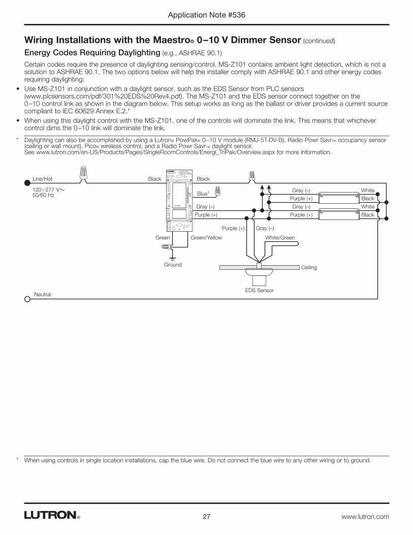
* Daylighting can also be accomplished by using a Lutron® PowPak® 0 –10 V module (RMJ-5T-DV-B), Radio Powr SavrTM occupancy sensor (ceiling or wall mount), Pico® wireless control, and a Radio Powr SavrTM daylight sensor. See www.lutron.com/en-US/Products/Pages/SingleRoomControls/Energi_TriPak/Overview.aspx for more information.
Wiring Installations with the Maestro® 0 – 10 V Dimmer Sensor (continued)
Energy Codes Requiring Daylighting (e.g., ASHRAE 90.1)
Certain codes require the presence of daylighting sensing/control. MS-Z101 contains ambient light detection, which is not a solution to ASHRAE 90.1. The two options below will help the installer comply with ASHRAE 90.1 and other energy codes requiring daylighting:
• Use MS-Z101 in conjunction with a daylight sensor, such as the EDS Sensor from PLC sensors (www.plcsensors.com/pdf/301%20EDS%20Rev4.pdf). The MS-Z101 and the EDS sensor connect together on the 0 –10 control link as shown in the diagram below. This setup works as long as the ballast or driver provides a current source compliant to IEC 60629 Annex E.2.*
• When using this daylight control with the MS-Z101, one of the controls will dominate the link. This means that whichever control dims the 0 –10 link will dominate the link.
m301551
OccLrnFixdVac
ModeHiMedLowMin
PIR
120 – 277 V~ 50 / 60 Hz 8 A
Alt
TURN OFF POWERARRETEZ LE COURANTDESCONECT LA CORRIENTE Up
Coopersburg, PA
800.523.9466lutron.com
Purple (+)
Purple (+)
Purple (+)
Purple (+)
Gray (–)
Gray (–)
Gray (–)
Gray (–)
CeilingGround
Green Green/Yellow White/Green
Black Black
Black
Black
White
White
Neutral
Line/Hot
Blue1120 – 277 V~ 50/60 Hz
EDS Sensor
1 When using controls in single location installations, cap the blue wire. Do not connect the blue wire to any other wiring or to ground.
28
Application Note #536
www.lutron.com®
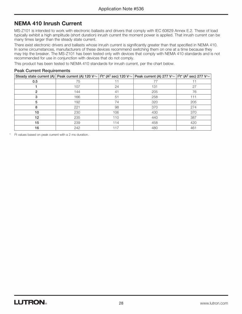
NEMA 410 Inrush CurrentMS-Z101 is intended to work with electronic ballasts and drivers that comply with IEC 60629 Annex E.2. These of load typically exhibit a high amplitude (short duration) inrush current the moment power is applied. That inrush current can be many times larger than the steady state current.There exist electronic drivers and ballasts whose inrush current is significantly greater than that specified in NEMA 410. In some circumstances, manufacturers of these devices recommend switching them on one at a time because they may trip the breaker. The MS-Z101 has been tested only with devices that comply with NEMA 410 standards and is not recommended for use in conjunction with devices that do not comply.This product has been tested to NEMA 410 standards for inrush current, per the chart below.
Peak Current RequirementsSteady state current (A) Peak current (A) 120 V~ I2t* (A2 sec) 120 V~ Peak current (A) 277 V~ I2t* (A2 sec) 277 V~
0.5 75 11 77 111 107 24 131 272 144 41 205 763 166 51 258 1115 192 74 320 2058 221 98 370 27410 230 106 430 37012 235 110 440 38715 239 114 458 42016 242 117 480 461
* I2t values based on peak current with a 2 ms duration.
29
Application Note #536
www.lutron.com®
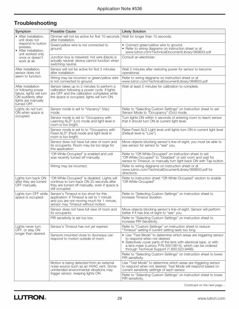
TroubleshootingSymptom Possible Cause Likely Solution• After installation,
unit does not respond to button presses.
• After installation, unit worked only once or doesn’t work at all.
Dimmer will not be active for first 10 seconds after installation.
Wait for longer than 10 seconds.
Green/yellow wire is not connected to ground.
• Connect green/yellow wire to ground.• Refer to wiring diagrams on instruction sheet or at
www.lutron.com/TechnicalDocumentLibrary/369833.pdfJunction box is miswired: hot wire (black) is actually neutral; device cannot function when switching neutral.
Consult an electrician.
After installation, sensor does not seem to function.
Sensor will not be active for first 2 minutes after installation.
Wait 2 minutes after restoring power for sensor to become operational.
Wiring may be incorrect or green/yellow wire is not connected to ground.
Refer to wiring diagrams on instruction sheet or at www.lutron.com/TechnicalDocumentLibrary/369833.pdf
After installation or following power failure, lights will turn ON suddenly after lights are manually turned OFF.
Sensor takes up to 2 minutes to perform a calibration following a power cycle. If lights are OFF and the calibration completes while the space is occupied, lights will turn ON.
Wait at least 2 minutes for calibration to complete.
Lights do not turn ON when space is occupied.
Sensor mode is set to “Vacancy” (Vac) mode.
Refer to “Selecting Custom Settings” on instruction sheet to set Sensor Mode to “Occupancy” (Occ) mode.
Sensor mode is set to “Occupancy with Learning ALD” (Lrn) mode and light level in room is too bright.
Turn lights ON within 5 seconds of entering room to teach sensor that it should turn ON at current light level.
Sensor mode is set to to “Occupancy with Fixed ALD” (Fixd) mode and light level in room is too bright.
Raise Fixed ALD Light level until lights turn ON in current light level (Default level is “Low”).
Sensor does not have full view of room and its occupants. Room may be too large for this application.
Move objects blocking sensor’s line-of-sight; you must be able to see sensor for sensor to “see” you.
“Off-While-Occupied” is enabled and unit was recently turned off manually.
Refer to “Off-While-Occupied” on instruction sheet to set “Off-While-Occupied” to “Disabled” or exit room and wait for sensor to Timeout, or manually turn light back ON with Tap button.
Wiring may be incorrect. Refer to wiring diagrams on instruction sheet or at www.lutron.com/TechnicalDocumentLibrary/369833.pdf for directions.
Lights turn back ON after they are turned OFF manually.
“Off-While-Occupied” is disabled. Lights will continue to turn back ON 25 seconds after they are turned off manually, even if space is still occupied.
Refer to instruction sheet “Off-While-Occupied” section to enable “Off-While-Occupied”.
Lights turn OFF while space is occupied.
Sensor’s Timeout is too short for this application: if Timeout is set to 1 minute and you are not moving much for 1 minute, sensor may Timeout without motion.
Refer to “Selecting Custom Settings” on instruction sheet to increase Timeout duration.
Sensor does not have full view of room and its occupants.
Move objects blocking sensor’s line-of-sight. Sensor will perform better if it has line-of-sight to “see” you.
PIR sensitivity is set too low. Refer to “Selecting Custom Settings” on instruction sheet to increase PIR Sensitivity.
Lights never turn OFF, or stay ON longer than desired.
Sensor’s Timeout has not yet expired. Refer to “Custom Settings” on instruction sheet to reduce “Timeout” setting if current setting lasts too long.
Sensors mounted close to doorways can respond to motion outside of room.
• Use “Test Mode” to determine which areas are triggering sensor to respond when not desired.
• Selectively cover parts of the lens with electrical tape, or with a lens mask (Lutron® P/N 50013614), which can be ordered through Technical Support (1.800.523.9466).
Refer to “Selecting Custom Settings” on instruction sheet to lower PIR sensitivity.
Motion is being detected from an external noise source such as an HVAC vent. Some unintended environmental vibrations may trigger sensor, keeping lights ON.
Use “Test Mode” to determine which areas are triggering sensor to respond when not desired. Test Mode will respond based on current sensitivity settings of each sensor.Refer to “Selecting Custom Settings” on instruction sheet to lower PIR sensitivity.
Continued on the next page…
30
Application Note #536
www.lutron.com®
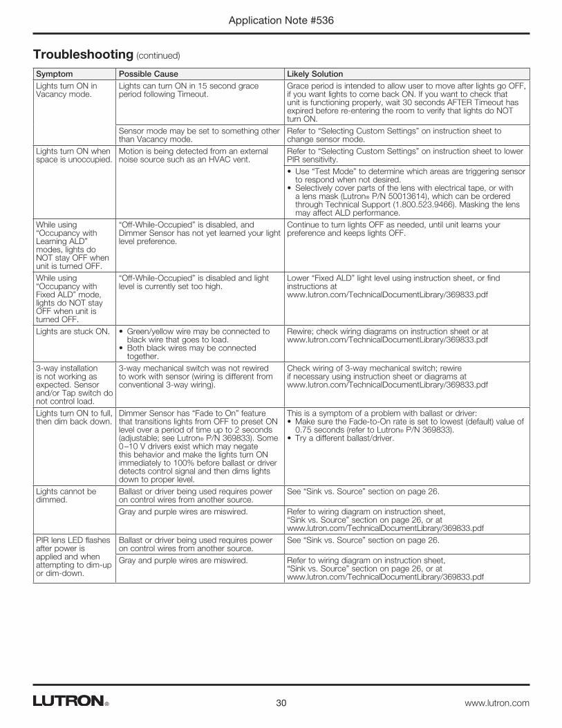
Troubleshooting (continued)
Symptom Possible Cause Likely SolutionLights turn ON in Vacancy mode.
Lights can turn ON in 15 second grace period following Timeout.
Grace period is intended to allow user to move after lights go OFF, if you want lights to come back ON. If you want to check that unit is functioning properly, wait 30 seconds AFTER Timeout has expired before re-entering the room to verify that lights do NOT turn ON.
Sensor mode may be set to something other than Vacancy mode.
Refer to “Selecting Custom Settings” on instruction sheet to change sensor mode.
Lights turn ON when space is unoccupied.
Motion is being detected from an external noise source such as an HVAC vent.
Refer to “Selecting Custom Settings” on instruction sheet to lower PIR sensitivity.• Use “Test Mode” to determine which areas are triggering sensor
to respond when not desired.• Selectively cover parts of the lens with electrical tape, or with
a lens mask (Lutron® P/N 50013614), which can be ordered through Technical Support (1.800.523.9466). Masking the lens may affect ALD performance.
While using “Occupancy with Learning ALD” modes, lights do NOT stay OFF when unit is turned OFF.
“Off-While-Occupied” is disabled, and Dimmer Sensor has not yet learned your light level preference.
Continue to turn lights OFF as needed, until unit learns your preference and keeps lights OFF.
While using “Occupancy with Fixed ALD” mode, lights do NOT stay OFF when unit is turned OFF.
“Off-While-Occupied” is disabled and light level is currently set too high.
Lower “Fixed ALD” light level using instruction sheet, or find instructions at www.lutron.com/TechnicalDocumentLibrary/369833.pdf
Lights are stuck ON. • Green/yellow wire may be connected to black wire that goes to load.
• Both black wires may be connected together.
Rewire; check wiring diagrams on instruction sheet or at www.lutron.com/TechnicalDocumentLibrary/369833.pdf
3-way installation is not working as expected. Sensor and/or Tap switch do not control load.
3-way mechanical switch was not rewired to work with sensor (wiring is different from conventional 3-way wiring).
Check wiring of 3-way mechanical switch; rewire if necessary using instruction sheet or diagrams at www.lutron.com/TechnicalDocumentLibrary/369833.pdf
Lights turn ON to full, then dim back down.
Dimmer Sensor has “Fade to On” feature that transitions lights from OFF to preset ON level over a period of time up to 2 seconds (adjustable; see Lutron® P/N 369833). Some 0 –10 V drivers exist which may negate this behavior and make the lights turn ON immediately to 100% before ballast or driver detects control signal and then dims lights down to proper level.
This is a symptom of a problem with ballast or driver:• Make sure the Fade-to-On rate is set to lowest (default) value of
0.75 seconds (refer to Lutron® P/N 369833).• Try a different ballast/driver.
Lights cannot be dimmed.
Ballast or driver being used requires power on control wires from another source.
See “Sink vs. Source” section on page 26.
Gray and purple wires are miswired. Refer to wiring diagram on instruction sheet, “Sink vs. Source” section on page 26, or at www.lutron.com/TechnicalDocumentLibrary/369833.pdf
PIR lens LED flashes after power is applied and when attempting to dim-up or dim-down.
Ballast or driver being used requires power on control wires from another source.
See “Sink vs. Source” section on page 26.
Gray and purple wires are miswired. Refer to wiring diagram on instruction sheet, “Sink vs. Source” section on page 26, or at www.lutron.com/TechnicalDocumentLibrary/369833.pdf

Contact Information
WORLD HEADQUARTERSUSALutron Electronics Co., Inc. 7200 Suter Road Coopersburg, PA 18036-1299TEL: +1.610.282.3800 FAX: +1.610.282.1243 Toll-Free: 1.888.LUTRON1 Technical Support: [email protected] and South America Technical HotlinesUSA, Canada, Caribbean:1.800.523.9466Mexico:+1.888.235.2910Central/South America:+1.610.282.6701
EUROPEAN HEADQUARTERSUnited KingdomLutron EA Ltd. 6 Sovereign Close London, E1W 3JF United KingdomTEL: +44.(0)20.7702.0657 FAX: +44.(0)20.7480.6899 FREEPHONE (UK): 0800.282.107 Technical Support: +44.(0)[email protected]
ASIAN HEADQUARTERSSingaporeLutron GL Ltd. 15 Hoe Chiang Road #07-03, Tower 15 Singapore 089316TEL: +65.6220.4666 FAX: +65.6220.4333 Technical Support: [email protected] Technical HotlinesNorthern China: 10.800.712.1536Southern China: 10.800.120.1536Hong Kong: 800.901.849Indonesia: 001.803.011.3994Japan: +81.3.5575.8411Macau: 0800.401Taiwan: 00.801.137.737Thailand: 001.800.120.665853Other Countries: +65.6220.4666
Application Note #536
Lutron Electronics Co., Inc.7200 Suter RoadCoopersburg, PA 18036-1299 U.S.A.P/N 048536 Rev. B 04/2015
31®
Lutron, Maestro, Pico and PowPak are registered trademarks and Radio Powr Savr is a trademark of Lutron Electronics Co., Inc.