
Aesa vs Pesa
30
Active Phased Array Radar Systems Dr. Yasser Al-Rashid Lockheed Martin MS2 Radar Systems [email protected] (856)722-6029 November 17, 2009
Transcript of Aesa vs Pesa

Active Phased Array Radar Systems
Dr. Yasser Al-RashidLockheed Martin MS2
Radar Systems [email protected]
(856)722-6029
November 17, 2009
2
Outline
• Radar System Components – Definition of Active Phased Array Radar System– Benefits of Active Array– Active Array System Design and Analysis
• Advanced Active Array Architecture– Definition of Digital Phased Array Radar System– Benefits of Digital Array– Examples of Phased Array Radar Systems
• Polarimetric Phased Array – Definition of Dual pol Configurations– Benefits of Dual pol Phased Array
• Multi-Mission Phased Array Enablers– Simultaneous Multi Beams (DBF)– Multi Frequencies
• System Cost and Maintenance Considerations

3
What is an ‘Active’ Phased Array?
• Basic definition: an array of radiating antenna elements having transmit and receive active components at each element (T/R modules)
– High-power amplifiers (HPA) for transmit– Low-noise amplifiers (LNA) for receive– Monolithic Microwave Integrated Circuits (MMIC)
• Solid-state semiconductor components provide signal gain - not vacuum tubes
– Solid-state technologies generally associated with the substrate material • Gallium Arsenide (GaAs)• Silicon Germanium (SiGe)• Silicon Carbide (SiC)• Gallium Nitride (GaN)
– Tube technologies• Klystron• Cross-field amplifiers (CFA)• Traveling wave tube (TWT)

4
Active Radar Major Components
• Antenna – Radiating elements– T/R module– Beamformer – Beam steering computer
• Exciter (waveform generator)• Receiver (RF signal to digital)• Signal Processor (target detection processing) • Radar Controller (Synchronize, Control and
schedule radar operation)

5
Radar System Configurations
Digital Signal
ProcessorControl
Computer
Mechanical Steering
Digital Signal
ProcessorControl
Computer
Exciter Exciter
Beam Steering
Computer(phase control)
Digital Signal
ProcessorControl Computer
Exciter
Beam Steering
Computer (phase control)
Passive Rotating Dish Radar System
Passive Phased Array Radar System
Active Phased Array Radar System
Transmitter
Radar System Design Evolution Over TimeRadar System Design Evolution Over Time
Receiver
Down ConverterADC
LNA
HPA
LN
AH
PA LN
A
Transmitter
HPA HPA
ReceiverDown Converter
T/R ModulesPer Element
Receiver
Down ConverterADC
LNA
Digital Signal
ProcessorControl
Computer
Mechanical Steering
Digital Signal
ProcessorControl
Computer
Exciter Exciter
Beam Steering
Computer(phase control)
Digital Signal
ProcessorControl Computer
Exciter
Beam Steering
Computer (phase control)
Passive Rotating Dish Radar System
Passive Phased Array Radar System
Active Phased Array Radar System
Transmitter
Radar System Design Evolution Over TimeRadar System Design Evolution Over Time
Receiver
Down ConverterADC
LNA LNA
HPA
LN
AH
PA LN
A
Transmitter
HPAHPA HPAHPA
ReceiverDown Converter
T/R ModulesPer Element
Receiver
Down ConverterADC
LNA

6
Key Active/Passive Design Differences
• Passive– Antenna driven by single large
transmitter amplifier (HPA)– First receive LNA after beam is
formed– Large signal loss between radiating
element and transmitter/LNA– Antenna connects to transmitter and
receiver
• Active– T/R module behind each radiating
element– Transmitter distributed through
antenna in many small HPAs– First LNA distributed through antenna
in many small LNAs– Small signal loss between HPA/LNA
and radiating element– Antenna is transmitter and receiver
HPA
LN
AH
PA LN
A
Transmitter
ReceiverLNA
Exciter
HPA
Receiver
Exciter
Bea
mfo
rmer
Bea
mfo
rmer
Transmit/Receive losses
Transmit/Receive losses
Pas
sive
Act
ive
T/R module
Active Antenna is HPA and LNA Active Antenna is HPA and LNA ––Passive Antenna Connects to HPA and LNAPassive Antenna Connects to HPA and LNA

7
Active Array Radar System Benefits Summary
• Design and operation– Replace waveguide (radar plumbing) with cables– No tube warm-up time or pulsing limitations
• Reliability– Mean-time between failure generally higher (better) for
solid-state electronics than tubes– Graceful degradation performance with component
failures• Performance
– Noise figure - > improved detection sensitivity– Clutter attenuation - > improved detection sensitivity
in the presence of clutter• Enabler of digital beamforming
8
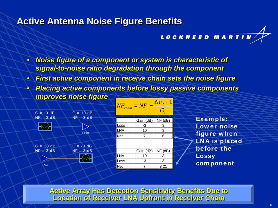
Active Antenna Noise Figure Benefits
• Noise figure of a component or system is characteristic of signal-to-noise ratio degradation through the component
• First active component in receive chain sets the noise figure• Placing active components before lossy passive components
improves noise figure
LNA
1
21
1G
NFNFNFchain-
+=G = -3 dBNF = 3 dB
G = 10 dBNF = 3 dB
LNA
G = 10 dBNF = 3 dB
G = -3 dBNF = 3 dB
Example: Lower noise figure when LNA is placed before the Lossy component
Gain (dB) NF (dB)Loss -3 3LNA 10 3Net 7 6
Gain (dB) NF (dB)LNA 10 3Loss -3 3Net 7 3.21
Active Array Has Detection Sensitivity Benefits Due toLocation of Receiver LNA Upfront in Receiver Chain

9
Clutter Attenuation
• System capability to reduce clutter interference is limited by hardware instability errors
– Pulse to pulse phase/amplitude errors– Intra-pulse noise
• Significant contributors– Analog-digital converter (ADC)– Down-conversion 1st Local Oscillator (LO)– High-power amplifiers (HPA)– Low-noise amplifiers (LNA)– Exciter/waveform generator
• Active Antenna improves system clutter attenuation – Errors de-correlate across distributed HPA/LNA
10
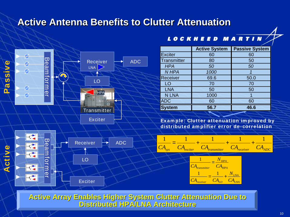
Active Antenna Benefits to Clutter Attenuation
Transmitter
ReceiverLNA
Exciter
HPA
Receiver
Exciter
Bea
mfo
rmer
Bea
mfo
rmer
Pass
ive
Act
ive
ADC
LO
ADC
LO
Example: Clutter attenuation improved by distributed amplifier error de-correlation
Active System Passive SystemExciter 60 60Transmitter 80 50
HPA 50 50N HPA 1000 1
Receiver 69.6 50.0LO 70 70LNA 50 50N LNA 1000 1
ADC 60 60System 56.7 46.6
ADCreceiverrtransmitteexcitersys CACACACACA11111
+++=
LNA
LNA
LOreceiver
HPA
HPA
rtransmitte
CAN
CACA
CAN
CA
+=
=
11
1
Active Array Enables Higher System Clutter Attenuation Due to Active Array Enables Higher System Clutter Attenuation Due to Distributed HPA/LNA ArchitectureDistributed HPA/LNA Architecture

11
Performance Analysis Example• Example systems with representative parameters
– Passive• 1000 elements• 1 Mega-watt transmitter• 1% transmit duty• 10 kW average power• 20 kW prime power at 50% PAE
– Active• 1000 elements• 5 W T/R module• 10% transmit duty• 500 W average power• 2 kW prime power at 25% PAE
( ) ...det3
24
4 LLLLkTSNRGGPR
sigprortsys
rtt
pstl
=
rtsys
rtut
LLTGGDP
=:FactorSensivity Roundtrip
Equal detection performance:Passive system – high-peak power, low dutyActive system – low-peak power, high duty
Passive ActiveT/R Module Power - Watts 5Number of Elements 1000 1000Gain of Element - dB 3.00 3.00Transmit Power (Pt) - Watts 100000 5000Transmit loss (Lt) - dB 3 1.5Receive Gain (Gr) - dB 30 30Receive loss (Lr) - dB 3 1.5System Noise temperture (Tsys) 1000 1000Transmit Duty (Du) 1% 10%Round-trip Sensitivity Factor 24.0 24.0
Active and Passive Radar Systems Can Be Designed to Provide Same Detection Performance With Different Operating Methodologies

12
Active Antenna Enables Digital Beamforming
• Digital beamforming is digitization of radar signal at the radiating element / sub-array level
• Beams are formed in digital domain using digital computation hardware
– Number of beams formed constrained by computation latency and data throughput
• Digital beamforming affords multiple simultaneous beams and improved System instantaneous dynamic range (IDR) and clutter attenuation
• Multiple beams can be employed in analog beamforming– Additional RF losses (degraded detection sensitivity)– RF hardware complexity to incorporate multiple beam
analog networks

13
Advanced System Configurations
Exciter
Control Computer
Beam Steering
Computer
Active Phased Array Radar
System
Digital at Subarray Level Radar System
Digital at Element Level Radar System
Advancement in Active Phased Array ArchitectureAdvancement in Active Phased Array Architecture
HPA
LN
AH
PA LN
A
Digital Signal
ProcessorH
PA LN
AH
PA LN
A
Digital Beamformer
ReceiverDown Converter
ReceiverDown Converter
Receiver (1-N)Down Converter
ADC
Digital Beamformer
On Array Components
On Array Components
Digital Signal
ProcessorControl Computer
Exciter
HPA
LN
AH
PA LN
A
ReceiverDown Converter
T/R ModulesPer ElementOn Array Components
Control Computer
T/R ModulesPer Element
Beam Steering
Computer (phase & amp control)
ExciterExciter ReceiverDown Converter
ReceiverDown Converter
Transceiver (1-M)
Per Element
Digital Signal
Processor
T/R ModulesPer Element
Beam Steering
Computer (phase & amp control)
Exciter
Control Computer
Beam Steering
Computer
Active Phased Array Radar
System
Digital at Subarray Level Radar System
Digital at Element Level Radar System
Advancement in Active Phased Array ArchitectureAdvancement in Active Phased Array Architecture
HPA
LN
AH
PA LN
A
Digital Signal
ProcessorH
PA LN
AH
PA LN
A
Digital Beamformer
ReceiverDown Converter
ReceiverDown Converter
Receiver (1-N)Down Converter
ADC
Digital Beamformer
On Array Components
On Array Components
Digital Signal
ProcessorControl Computer
Exciter
HPA
LN
AH
PA LN
A
ReceiverDown Converter
T/R ModulesPer ElementOn Array Components
Control Computer
T/R ModulesPer Element
Beam Steering
Computer (phase & amp control)
ExciterExciter ReceiverDown Converter
ReceiverDown Converter
Transceiver (1-M)
Per Element
Digital Signal
Processor
T/R ModulesPer Element
Beam Steering
Computer (phase & amp control)

14
Future Work Trends
• Everything gets smaller, lighter• More components get integrated inside Antenna
– All transmitter, receiver, exciter equipment condensed into the Antenna ‘box’• Move A/D converter closer to radiating element – improves system
dynamic range– All digital beam-forming done inside the Antenna ‘box’– Digital beam-forming introduces capability of multiple simultaneous formed
beams• Wide-band gap HPA devices (example SiC T/R Modules)
– Higher T/R module output power– Higher efficiency
Radar System Design Evolution Over Time
Beamformer
HPA LNA
ADC
Passive Antenna
Down-convert
Beamformer
ADC
Active Antenna
Down-convert
Down-convert
BeamformerFuture Active
Antenna
ADC

15
Benefits of Digital Beam-forming: Multiple Simultaneous Beams
• Cover same volume with fewer dwell positions
• Additional radar timeline made available
– Shorter frame time -> quick target detection
– Longer waveform integration -> higher detection sensitivity, clutter mitigation
– Incorporate multiple simultaneous radar functions
• Example: Number of dwell locations reduced by factor of 2 via multiple digital beams
– Increase waveform integration time by 2X – or -
– Reduce search frame time by 2X
Analog Beamforming: One beam at a time
Digital Beamforming: Pair of beams at a time
Dwells1-10
Dwells1-5
1 2 3 4 5
6 7 8 9 10
Azimuth
Ele
vatio
n
Azimuth
Ele
vatio
n
1 2 3 4 5
1 2 3 4 5
Digital Beam Forming Affords Simultaneous Beams –Benefits Radar Timeline

16
Benefits of Digital Beamforming: Dynamic Range
• Analog beam forming:– Input to ADC is formed beam
signal: summation of analog signals
– System IDR limited by ADC IDR• Digital beam forming
– Input to ADC is element/sub-array analog signal: formed beam is summation of digital signals
– System IDR is N X ADC IDR
Beamformer
Receiver
ADC
Receiver
Receiver
Receiver
Receiver
Receiver
AD
C
AD
C
AD
C
AD
C
AD
C
Digital Beamformer
Sum Beam
Sum Beam
x1 x2 … xN x1 x2 … xN
Example: IDR improved by distributed ADC, further up receive chain
Input to ADC is beam former output
Input to ADC is element
output
Beam forming on digital data
Beam forming on analog (RF)
signals
RF Signal Input to Each Array ElementRF Signal Input to Each Array Element
Digital Beam Forming Benefits SystemDynamic Range Due to Distributed ADC
ABF DBFADC IDR (dB) 60 60N ADC 1 50System IDR (dB) 60 77

17
Examples of Multi-function PAR Radars
NWRT (2003)
Passive Phased Array
COBRA(1980’s)
EQ-36(2010)
SPY-4 VSR(2008)
Active Phased Array
R&D(2006)
Digital Phased Array
SPY-1A(1970’s)

18
Dual Pol Configuration Modes
• Alternating Transmit and Simultaneous Receive (ATSR) Mode
• Simultaneous Transmit and Simultaneous Receive (STSR) Mode
• Alternating Transmit and Alternating Receive (ATAR) Mode

19
Alternating Transmit and Simultaneous Receive (ATSR) Mode
Alternate Transmit and Simultaneous Receive (ATSR) Mode:
– Vertical pol transmit and simultaneously receive from both polarizations; then
– Horizontal pol transmit and simultaneously receive from both polarizations
• + compatibility with existing NCAR algorithms• + Linear Depolarization Ratio (LDR) can be measured• + achievable cross polarization isolation (-25 dB)• + common waveform generator for both polarization• -- need to use switch, • -- requires longer scan time
Dual Pol ATSR mode

20
Simultaneous Transmit and Simultaneous Receive (STSR) Mode
Simultaneous Transmit and Simultaneous Receive (STSR) Mode:
– Simultaneous independent transmission of two orthogonally polarized channels and simultaneous receive from both channels
Dual Pol STSR mode
• + compatibility with current NEXRAD algorithms• + provide circular polarization capability• + efficient scanning time • -- must match/balance two receivers, control gain drifting,
temperature • -- challenging cross polarization requirements (-45 dB)

21
Alternating Transmit and Alternating Receive (ATAR) Mode
Alternating Transmit and Alternating Receive (ATAR) Mode:
– Vertical pol transmit and receive co-polar; then
– Horizontal pol transmit and receive co-polar
Dual Pol STSR mode
• + achievable cross polarization isolation (-25 dB)• + only one receiver required (no need to balance receivers) • -- -- need to use switch, • -- requires longer scan time,• --unsuitable for batch mode, staggered or variable PRTs
22
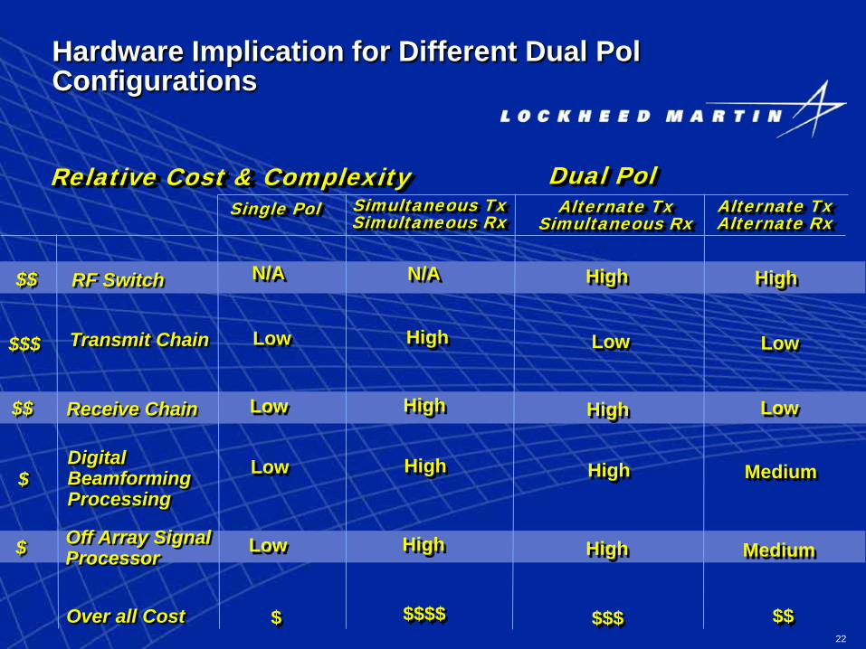
Hardware Implication for Different Dual Pol Configurations
RF Switch N/A
Single Pol Simultaneous Tx Simultaneous Rx
Dual PolAlternate Tx
Simultaneous RxAlternate Tx Alternate Rx
N/A High High
Transmit Chain HighLow Low Low
Receive Chain HighLow High Low
Digital Beamforming Processing
HighLow High Medium
Off Array Signal Processor
HighLow High Medium
Over all Cost $$$$ $$$ $$$
$$$
$$
$
$
$$
Relative Cost & Complexity

23
Multi-Mission Active Radar
• With technological advances provided by Solid State Phased Arrays simultaneous scheduling of multiple radar timelines is achievable
– Within a single mission the use of beam spoiling on transmit and DBF on receive can reduce the scan time significantly to support multi-mission operation.
– Across multiple missions, the simultaneous use of multiple frequencies that are sufficiently spaced allows the multiplexing necessary to support multi-mission operation.
Digital Phased Arrays With Multiple Frequencies Provide the Capabilities for Multi-Mission Operations

24
Multi Frequency Channels
• Multi frequency channels radar enable multi-mission and multi-face radar operation
• Point target operation 10 Mhz frequency separation provides enough isolation for simultaneous multi-mission operation without interference
x MHz
y MHz
f1 f2 f3 f4
Mission A Mission B Mission C
Face 1 Face 3 Face 2 Face 4
Frequency
Δf1
Δf= Transmitted Pulse Isntantenous Band Width
Δf2 Δf3 Δf4
4 Active Antenna Fixed Faces(top view)

25
Active vs. Passive Design Selection Criteria
• Selection of an active system based on the performance and functions that are desired from the system and the cost that is desired for the system
• Analysis needs to consider cost, performance and reliability
Passive Active
Cost More expensive than rotating dish Higher cost than Passive, but has potential cost reduction with time
Performance Low transmit duty – limits functionsLower signal stability – limits capability in clutter environments
High duty enables more functionsHigh signal stability – enhanced capability in clutter environments
Reliability Lower reliability• Tube transmitter is potential single-
point failure• Very High signal levels lead to
mechanical switches (i.e. waveguide switches)
High reliability –• Multiple HPAs distributed, graceful
degradation• Lower signal levels allow solid-
state switches

26
Summary
• Active Phased Array Antenna has signal transmit and receive amplifiers in the Antenna
– Antenna is the transmitter and receiver• Active arrays provide reliability and performance improvements
over passive systems– All solid-state design and components– Graceful degradation
• Design of active radar systems introduce additional complexities– Power, cooling, calibration– Additional requirements on antenna
• Active Radar system development is hardly new – Systems exist• Lockheed Martin has produced an advanced solid-state radar
demonstrator– S4R: Risk reduction for near and far term business pursuits
• In the future, components will be smaller, lighter and the Antenna will have much more capability

27
28
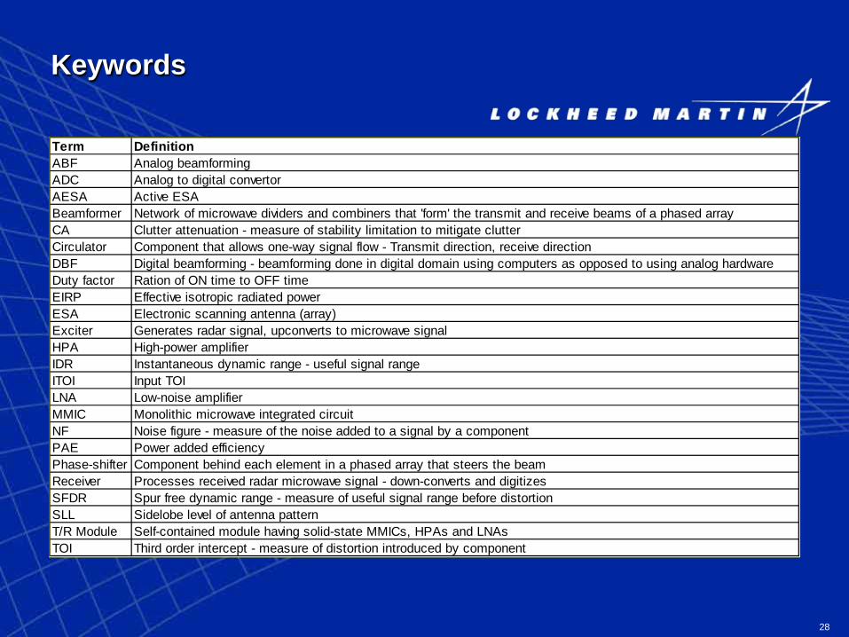
Keywords
Term DefinitionABF Analog beamformingADC Analog to digital convertorAESA Active ESABeamformer Network of microwave dividers and combiners that 'form' the transmit and receive beams of a phased arrayCA Clutter attenuation - measure of stability limitation to mitigate clutterCirculator Component that allows one-way signal flow - Transmit direction, receive directionDBF Digital beamforming - beamforming done in digital domain using computers as opposed to using analog hardwareDuty factor Ration of ON time to OFF timeEIRP Effective isotropic radiated powerESA Electronic scanning antenna (array)Exciter Generates radar signal, upconverts to microwave signalHPA High-power amplifierIDR Instantaneous dynamic range - useful signal rangeITOI Input TOILNA Low-noise amplifierMMIC Monolithic microwave integrated circuitNF Noise figure - measure of the noise added to a signal by a componentPAE Power added efficiencyPhase-shifter Component behind each element in a phased array that steers the beamReceiver Processes received radar microwave signal - down-converts and digitizesSFDR Spur free dynamic range - measure of useful signal range before distortionSLL Sidelobe level of antenna patternT/R Module Self-contained module having solid-state MMICs, HPAs and LNAsTOI Third order intercept - measure of distortion introduced by component

29
Weather Radar and Polarization
• In general, weather radars send and receive microwaves at one polarization, usually horizontal.
• Dual Polarization is used to obtain additional information on the nature of the targets.
– Potential non cooperative target recognition• Comparing the relative strength and phase of the horizontal
and vertical returns determines scatters orientation • Three dual pol weather modes of operations:
– Alternate transmit and alternate receive– Alternate transmit and simultaneous receive (NCAR)– Simultaneous transmit and simultaneous receive
(NEXRAD)

30
Benefits of Polarimetric Phase Array Radar for Weather Sensing
• Accurate hydrometeor classification • Distinction of rain from other types of
hydrometeors• Improved ground clutter cancellation • Improved compensation for reflectivity biases• Estimation of rain fall rate