
Aerospace Electronic Systems - Honeywell · PDF fileAerospace Electronic Systems SYSTEM ......
108
Aerospace Electronic Systems SYSTEM INSTALLATION MANUAL BENDIX/KING ® MK-XXI Helicopter Enhanced Ground Proximity Warning System (EGPWS) TAWS TSO-C151b Class B Equipment Manual Number 060-4314-101 Revision A, June 16, 2003
Transcript of Aerospace Electronic Systems - Honeywell · PDF fileAerospace Electronic Systems SYSTEM ......

Aerospace Electronic Systems
SYSTEMINSTALLATION MANUAL
BENDIX/KING
®
MK-XXIHelicopter Enhanced Ground Proximity Warning System
(EGPWS)
TAWS TSO-C151b Class B Equipment
Manual Number 060-4314-101Revision A, June 16, 2003

TRADEMARK NOTICE
PATENT PENDING
BENDIX/KING AND THE BENDIX/KING® LOGO ARE REGISTERED TRADEMARKS OF HONEYWELLINTERNATIONAL INC., U.S. PATENT & TRADEMARK OFFICE.
NOTICE
Unit repair must be accomplished by a Honeywell International Inc. approved INSTRUMENTSERVICE CENTER. WARRANTY is valid only when dust cover seal is intact.

Installation/Maintenance Manual Discrepancy Notification
The Honeywell Product Support Department maintains this manual. This manual supports the installation and/ormaintenance of the BENDIX/KING equipment and systems designated on the cover of this manual. If a discrepancy isfound in this manual, please mail or fax this form (or a copy) and a copy of the page(s) with the discrepancy noted. Therecommended change(s) will be evaluated and incorporated into the manual as necessary at the time of the next revision.
Honeywell International Inc.One Technology Center23500 West 105th StreetOlathe, KS 66061
Attention: MK-XXI Product Specialist`FAX: (913) 712-1306
Name: _________________________________________
Company: _________________________________________
Phone: _________________________________________
Fax:_________________________________________
Address:_________________________________________
_________________________________________
_________________________________________
_________________________________________
_________________________________________
Manual Number and Revision:_______________________________________________________________________
Discrepancy:_____________________________________________________________________________________
_____________________________________________________________________________________
_____________________________________________________________________________________
_____________________________________________________________________________________
_____________________________________________________________________________________
_____________________________________________________________________________________
_____________________________________________________________________________________
_____________________________________________________________________________________
_____________________________________________________________________________________
_____________________________________________________________________________________
_____________________________________________________________________________________
_____________________________________________________________________________________
_____________________________________________________________________________________

Honeywell Aerospace Electronic SystemsSYSTEM INSTALLATION MANUAL
MK-XXI EGPWS
DWD NO: 060-4314-101 MK-XXI Page iRev. A, June/2003
Table of Contents1 SECTION I – GENERAL INFORMATION..................................................................................................... 1-1
1.1 Introduction ............................................................................................................................................... 1-11.2 Purpose ...................................................................................................................................................... 1-11.3 Document Overview.................................................................................................................................. 1-11.4 Applicability of the System Installation Manual ....................................................................................... 1-2
1.4.1 Equipment Applicability.................................................................................................................... 1-21.5 MK-XXI EGPWS...................................................................................................................................... 1-3
1.5.1 Regional Terrain Database................................................................................................................. 1-31.6 System Description.................................................................................................................................... 1-3
1.6.1 Basic MK-XXI EGPWS System ....................................................................................................... 1-41.6.2 System Constraints ............................................................................................................................ 1-41.6.3 System Components .......................................................................................................................... 1-51.6.4 System Operation............................................................................................................................... 1-6
1.6.4.1 EGPWS Modes of Operation......................................................................................................... 1-61.6.4.2 Options........................................................................................................................................... 1-7
1.7 Technical Characteristics........................................................................................................................... 1-81.7.1 MK-XXI EGPWS Information .......................................................................................................... 1-81.7.2 MK-XXI Configuration Module Information.................................................................................... 1-81.7.3 MK-XXI Regional Terrain Database Information............................................................................. 1-8
1.8 Unit and Accessories Supplied .................................................................................................................. 1-91.8.1 MK-XXI EGPWS Computer ............................................................................................................. 1-91.8.2 MK-XXI EGPWS Configuration Module ......................................................................................... 1-91.8.3 MK-XXI EGPWS Install Kit ............................................................................................................. 1-91.8.4 MK-XXI EGPWS Regional Terrain Database ................................................................................ 1-10
1.9 Accessories Required But Not Supplied.................................................................................................. 1-111.9.1 Cable and Wire ................................................................................................................................ 1-11
1.10 Optional Accessories Not Supplied ......................................................................................................... 1-111.10.1 Optional GPS Antenna & GPS Antenna Installation Kit................................................................. 1-111.10.2 Optional Temperature Probe............................................................................................................ 1-111.10.3 Annunciators & Switches ................................................................................................................ 1-12
1.10.3.1 Optional Annunciator Install Kit.............................................................................................. 1-121.10.3.2 Optional Terrain Switching Kit ............................................................................................... 1-121.10.3.3 Other Vendors.......................................................................................................................... 1-13
1.10.4 PC Diagnostic Connection Components.......................................................................................... 1-131.10.5 Special Tools Required.................................................................................................................... 1-13
1.10.5.1 Crimping Tool – P1 ................................................................................................................. 1-131.10.5.2 Contact Positioner – P1............................................................................................................ 1-131.10.5.3 Insertion/Removal Tool – P1 ................................................................................................... 1-13
1.11 Regional Terrain Database Updates......................................................................................................... 1-142 SECTION II – INSTALLATION...................................................................................................................... 1-1
2.1 Introduction ............................................................................................................................................... 1-12.2 Unpacking And Inspecting Equipment...................................................................................................... 1-12.3 Equipment Installation Considerations ...................................................................................................... 1-1
2.3.1 General Considerations...................................................................................................................... 1-12.3.2 Avionics Cooling Considerations ...................................................................................................... 1-12.3.3 MK-XXI Installation Considerations................................................................................................. 1-2
2.3.3.1 MK-XXI Cooling Considerations.................................................................................................. 1-22.3.3.2 Installation/Location Considerations ............................................................................................. 1-22.3.3.3 Annunciator Lamp Considerations ................................................................................................ 1-32.3.3.4 Equipment Installation Procedure.................................................................................................. 1-32.3.3.5 Mechanical Installation Instructions .............................................................................................. 1-32.3.3.6 EGPWS Computer Installation Mounting ..................................................................................... 1-5
2.3.4 Configuration Module Installation..................................................................................................... 1-5

Honeywell Aerospace Electronic SystemsSYSTEM INSTALLATION MANUAL
MK-XXI EGPWS
DWD NO: 060-4314-101 MK-XXI Page iiRev. A, June/2003
2.3.4.1 Installation Considerations ............................................................................................................ 1-52.3.4.2 Installation Procedure .................................................................................................................... 1-6
2.3.5 Configuration Module Installation Assembly.................................................................................... 1-62.3.6 GPS Antenna Installation................................................................................................................. 1-102.3.7 Temperature Probe........................................................................................................................... 1-102.3.8 Display............................................................................................................................................. 1-102.3.9 Installation Constraints .................................................................................................................... 1-10
3 SECTION III – ELECTRICAL INTERCONNECTS ..................................................................................... 1-113.1 Introduction ............................................................................................................................................. 1-113.2 Purpose .................................................................................................................................................... 1-113.3 Applicable Part Numbers Subsection Description................................................................................... 1-113.4 Requirements and Limitations Subsection Description. .......................................................................... 1-113.5 Electrical Characteristics Subsection Description. .................................................................................. 1-113.6 Interface Subsection Description ............................................................................................................. 1-123.7 Installation Constraints ............................................................................................................................ 1-123.8 Planning Considerations – Description of Features and Options............................................................. 1-12
3.8.1 Encoding Altimeters / Blind Encoders / Digital Air Data Computers (DADC) .............................. 1-123.8.1.1 Altitude Monitor Option .............................................................................................................. 1-133.8.1.2 Encoding Altimeters That Are The Pilot’s Primary Altitude Reference...................................... 1-133.8.1.3 Aircraft Equipped With A Blind Encoder.................................................................................... 1-133.8.1.4 A Dedicated Blind Encoder ......................................................................................................... 1-13
3.8.2 Cockpit Lamps & Switches ............................................................................................................. 1-133.8.3 Audio ............................................................................................................................................... 1-143.8.4 GPS Antenna ................................................................................................................................... 1-143.8.5 Outside Air Temperature (OAT) Option ......................................................................................... 1-143.8.6 Display Option................................................................................................................................. 1-14
3.9 General Electrical Interface Information ................................................................................................. 1-153.9.1 Introduction ..................................................................................................................................... 1-153.9.2 Signal Interfaces .............................................................................................................................. 1-15
3.9.2.1 Grounds ....................................................................................................................................... 1-153.9.2.2 Primary Power Input.................................................................................................................... 1-153.9.2.3 DC Analog Inputs ........................................................................................................................ 1-163.9.2.4 ARINC 429/575 Digital Serial Bus Inputs .................................................................................. 1-163.9.2.5 RS-232 / RS-422 Digital Serial Bus ............................................................................................ 1-173.9.2.6 Discrete Inputs ............................................................................................................................. 1-193.9.2.7 Configuration Module Interface .................................................................................................. 1-193.9.2.8 GPS Antenna Input ...................................................................................................................... 1-193.9.2.9 OAT Excitation Output................................................................................................................ 1-203.9.2.10 Lamp Driver Outputs ............................................................................................................... 1-203.9.2.11 Audio Output ........................................................................................................................... 1-203.9.2.12 ARINC Digital Serial Output Busses....................................................................................... 1-21
3.9.3 Test Interface ................................................................................................................................... 1-223.9.3.1 RS-232 Maintenance Port ............................................................................................................ 1-223.9.3.2 GSE Present Discrete Input ......................................................................................................... 1-22
3.10 Interconnect Pinout Lists ......................................................................................................................... 1-233.10.1 Pinouts Listed by Designation ......................................................................................................... 1-233.10.2 Pinouts Listed by pin number .......................................................................................................... 1-26
3.11 Front View............................................................................................................................................... 1-283.12 Typical System Interconnect Wiring Diagram ........................................................................................ 1-303.13 Example System Interconnect Wiring Diagram ...................................................................................... 1-313.14 Interconnect Diagrams............................................................................................................................. 1-32
4 SECTION IV – SYSTEM INSTALLATION DESIGN .................................................................................... 1-14.1 Introduction ............................................................................................................................................... 1-14.2 Configuration Types (Categories) ............................................................................................................. 1-14.3 Design/Planning System Configuration Identification (ID) Selection...................................................... 1-2
4.3.1 Configuration Selection Tables.......................................................................................................... 1-3

Honeywell Aerospace Electronic SystemsSYSTEM INSTALLATION MANUAL
MK-XXI EGPWS
DWD NO: 060-4314-101 MK-XXI Page iiiRev. A, June/2003
4.3.1.1 Category 1, Aircraft / Mode Type Select ....................................................................................... 1-34.3.1.2 Category 2, Air Data Input Select.................................................................................................. 1-44.3.1.3 Category 3, Position Input Select................................................................................................... 1-94.3.1.4 Category 4, Terrain Display Select .............................................................................................. 1-124.3.1.5 Category 5, Input / Output Discrete Type Select ......................................................................... 1-134.3.1.6 Category 6, Audio Menu Select................................................................................................... 1-134.3.1.7 Category 7, Audio Output Level.................................................................................................. 1-134.3.1.8 Category 8, Altitude Monitor Options ......................................................................................... 1-144.3.1.9 Category 9, Terrain Display Alternate Pop Up Option................................................................ 1-144.3.1.10 Category 10, Attitude and Heading Select............................................................................... 1-154.3.1.11 Category 11, Display Option Select......................................................................................... 1-18
5 SECTION V - INSTALLATION CONFIGURATION & CHECKOUT.......................................................... 5-15.1 Introduction ............................................................................................................................................... 5-15.1.1 Installation Sequence ............................................................................................................................. 5-15.2 Installation – Aircraft Wiring Verification ................................................................................................ 5-25.3 Regional Terrain Database Card................................................................................................................ 5-2
5.3.1 Regional Terrain Database Card Installation ..................................................................................... 5-25.3.2 Regional Terrain Database Card Verification.................................................................................... 5-35.3.3 Regional Terrain Database Card Updates.......................................................................................... 5-3
5.4 Configuration Setup & Programming........................................................................................................ 5-45.4.1 Equipment Needed............................................................................................................................. 5-45.4.2 WinViews .......................................................................................................................................... 5-45.4.3 WinViews Operation ......................................................................................................................... 5-55.4.4 Configuration Module Programming Instructions ............................................................................. 5-55.4.5 Configuration String Format.............................................................................................................. 5-55.4.6 Configuration Module Programming Procedure................................................................................ 5-6
5.5 Post Installation Checkout ......................................................................................................................... 5-75.5.1 Information ........................................................................................................................................ 5-75.5.2 WinViews Command File Creation................................................................................................... 5-75.5.3 Adding WinViews CVT Items........................................................................................................... 5-85.5.4 Post Installation Checkout ................................................................................................................. 5-95.5.5 GPS Quick Check ............................................................................................................................ 5-105.5.6 Air Data Check ................................................................................................................................ 5-105.5.6.1 Altitude Encoder (9 wire Gillham/Graycode altitude) Check.......................................................... 5-105.5.6.2 Digital Air Data Input Check........................................................................................................... 5-115.5.7 Outside Air Temperature Check ...................................................................................................... 5-115.5.8 Internal GPS Receiver Check .......................................................................................................... 5-115.5.9 DISPLAY RANGE INPUT CHECK............................................................................................... 5-125.5.10 GPS/COM SUSCEPTIBILITY CHECK......................................................................................... 5-135.5.11 ATTITUDE & ROLL ...................................................................................................................... 5-135.5.12 MAGNETIC HEADING CHECK................................................................................................... 5-13
5.6 System Self-Test Procedure..................................................................................................................... 5-145.6.1 Self-Test Initiation ........................................................................................................................... 5-14
5.6.1.1 Self-Test Short and Long Cancel ................................................................................................. 5-145.6.2 Level 1 Self-Test.............................................................................................................................. 5-145.6.3 Level 2 Self-test ............................................................................................................................... 5-155.6.4 Self-test Level 3 - System Configuration......................................................................................... 5-15
6 SECTION VI - OPERATION ........................................................................................................................... 6-16.1 General Information................................................................................................................................... 6-1
7 SECTION VII – CERTIFICATION INFORMATION ..................................................................................... 7-17.1 Introduction ............................................................................................................................................... 7-17.2 Certification Procedure.............................................................................................................................. 7-1
7.2.1 Equipment Compatibility................................................................................................................... 7-17.2.2 Equipment Location........................................................................................................................... 7-17.2.3 TSO Category .................................................................................................................................... 7-17.2.4 Geometric Altitude ............................................................................................................................ 7-1

Honeywell Aerospace Electronic SystemsSYSTEM INSTALLATION MANUAL
MK-XXI EGPWS
DWD NO: 060-4314-101 MK-XXI Page ivRev. A, June/2003
7.2.4.1 Geometric Altitude Background .................................................................................................... 7-17.2.5 FAA Requirements ............................................................................................................................ 7-27.2.6 FAA Form 337................................................................................................................................... 7-27.2.7 Flight Manual Revision ..................................................................................................................... 7-27.2.8 Pilot Briefing ..................................................................................................................................... 7-2
7.3 License Requirements................................................................................................................................ 7-27.4 Instructions for Continued Airworthiness.................................................................................................. 7-2
7.4.1 MK-XXI EGPWS.............................................................................................................................. 7-27.4.2 Wires/Coax Cables ............................................................................................................................ 7-37.4.3 Annunciators/Relays.......................................................................................................................... 7-37.4.4 GPS Antenna ..................................................................................................................................... 7-37.4.5 Temperature Probe............................................................................................................................. 7-37.4.6 Regional Terrain Database Updates................................................................................................... 7-3
8 SECTION VIII – ABBREVIATIONS, ACRONYMS & DEFINITIONS ........................................................ 8-19 SECTION IX – ENVIRONMENTAL QUALIFICATION............................................................................... 9-110 SECTION X– CERTIFICATION DOCUMENTATION REFERENCES.................................................. 10-111 SECTION XI– APPROVED SENSORS..................................................................................................... 11-1
11.1 Encoding Altimeters And Blind Encoders............................................................................................... 11-111.2 GPS Sensors ............................................................................................................................................ 11-111.3 Supported Displays.................................................................................................................................. 11-2

Honeywell Aerospace Electronic SystemsSYSTEM INSTALLATION MANUAL
MK-XXI EGPWS
DWD NO: 060-4314-101 MK-XXI Page vRev. A, June/2003
LIST OF ILLUSTRATIONSFigure 1-1: System Block Diagram ........................................................................................................................... 1-6Figure 2-1: EGPWS Computer Outline Drawing ...................................................................................................... 1-4Figure 2-2: Standard Mounting ................................................................................................................................. 1-5Figure 2-3: Connector Rear View.............................................................................................................................. 1-6Figure 2-4: Connector Wire Interconnect .................................................................................................................. 1-7Figure 2-5: Connector Slide Lock ............................................................................................................................. 1-7Figure 2-6: Connector Backshell Connection............................................................................................................ 1-8Figure 2-7: Connector Spring Clip ............................................................................................................................ 1-8Figure 2-8: Connector Configuration Mount............................................................................................................. 1-9Figure 2-9: Front Connector with Configuration Module ......................................................................................... 1-9Figure 3-1: Front Panel Connector Orientation – J1 & GPS ANT .......................................................................... 1-28Figure 3-2: Rear View of J1 Connector & Pin Location ......................................................................................... 1-29Figure 3-3: Typical System Interconnect Wiring Diagram ..................................................................................... 1-30Figure 3-4: Example System Interconnect Wiring Diagram ................................................................................... 1-31Figure 3-5: Basic EGPWS Interconnect .................................................................................................................. 1-32Figure 3-6: Altitude Sensor Interconnect................................................................................................................. 1-33Figure 3-7: GPS Position Sensor Interconnect ........................................................................................................ 1-34Figure 3-8: Eaton Annunciator Switches................................................................................................................. 1-35Figure 3-9: Terrain Annunciator & Switches Interconnect ..................................................................................... 1-36Figure 3-10: West Coast Annunciator Interconnect ................................................................................................ 1-37Figure 3-11: Mid-Continent MD 41-1208 Interconnect .......................................................................................... 1-38Figure 3-12: Mid-Continent MD 41-1308 Interconnect .......................................................................................... 1-39Figure 3-13: IN 182/812 Wx Radar Indicator Interconnect..................................................................................... 1-40Figure 3-14: Terrain display interrconnect .............................................................................................................. 1-41Figure 3-15: Bendix/King EFIS 40/50 Interconnect................................................................................................ 1-42

Honeywell Aerospace Electronic SystemsSYSTEM INSTALLATION MANUAL
MK-XXI EGPWS
DWD NO: 060-4314-101 MK-XXI Page viRev. A, June/2003
List of TablesTable 1-1: Equipment Applicability .......................................................................................................................... 1-2Table 1-2: MK-XXI Unit Technical Specifications................................................................................................... 1-8Table 1-3: MK-XXI Configuration Module Specifications....................................................................................... 1-8Table 1-4: MK-XXI Regional Terrain Database Specifications................................................................................ 1-8Table 1-5: MK-XXI Regional Terrain Databases.................................................................................................... 1-10Table 2-1: MK-XXI Lamp/Switch Legends.............................................................................................................. 1-3Table 3-1: Pinouts Listed By Designation............................................................................................................... 1-25Table 3-2: Pin Assignment for Front Connectors - sorted by pin number............................................................... 1-27Table 4-1: Category ID Selection Table .................................................................................................................... 1-2Table 4-2: Aircraft / Mode Type Select..................................................................................................................... 1-3Table 4-3: Air Data Input Select................................................................................................................................ 1-4Table 4-4: Air Data Type 1........................................................................................................................................ 1-5Table 4-5: Air Data Type 2........................................................................................................................................ 1-5Table 4-6: Air Data Type 3........................................................................................................................................ 1-5Table 4-7: Air Data Type 4........................................................................................................................................ 1-5Table 4-8: Air Data Type 5........................................................................................................................................ 1-6Table 4-9: Air Data Type 5........................................................................................................................................ 1-6Table 4-10: Air Data Type 7...................................................................................................................................... 1-6Table 4-11: Air Data Type 8...................................................................................................................................... 1-6Table 4-12: Air Data Type 9...................................................................................................................................... 1-6Table 4-13: Air Data Type 10.................................................................................................................................... 1-6Table 4-14: Air Data Type 11.................................................................................................................................... 1-7Table 4-15: Air Data Type 13.................................................................................................................................... 1-7Table 4-16: Static Air Temperature Type 1............................................................................................................... 1-7Table 4-17: Static Air Temperature Type 2............................................................................................................... 1-8Table 4-18: Static Air Temperature Type 3............................................................................................................... 1-8Table 4-19: Static Air Temperature Type 5............................................................................................................... 1-8Table 4-20: Position Input Select .............................................................................................................................. 1-9Table 4-21: Position Input Type 0 ............................................................................................................................. 1-9Table 4-22: Position Input Type 1 ........................................................................................................................... 1-10Table 4-23: Position Input Type 2 ........................................................................................................................... 1-10Table 4-24: Position Input Type 3 ........................................................................................................................... 1-11Table 4-25: Position Input Type 4 ........................................................................................................................... 1-11Table 4-26: Terrain Display Select.......................................................................................................................... 1-12Table 4-27: Input/Output Discrete Type Select ....................................................................................................... 1-13Table 4-28: Audio Menu Type ................................................................................................................................ 1-13Table 4-29: Audio Output Level.............................................................................................................................. 1-13Table 4-30: Altitude Monitor Options ..................................................................................................................... 1-14Table 4-31: Terrain Display Alternate Pop Up Disable Option............................................................................... 1-14Table 4-32: Attitude and Heading Type .................................................................................................................. 1-15Table 4-33: Attitude and Heading Input Select Type 1 ........................................................................................... 1-15Table 4-34: Attitude and Heading Input Select Type 2 ........................................................................................... 1-16Table 4-35: Attitude and Heading Input Select Type 3 ........................................................................................... 1-16Table 4-36: Attitude and Heading Input Select Type 4 ........................................................................................... 1-16Table 4-37: Attitude and Heading Input Select Type 5 ........................................................................................... 1-16Table 4-38: Attitude and Heading Input Select Type 6 ........................................................................................... 1-16Table 4-39: Attitude and Heading Input Select Type 7 ........................................................................................... 1-17Table 4-40: Attitude and Heading Input Select Type 8 ........................................................................................... 1-17Table 4-41: Display Option Type ............................................................................................................................ 1-19Table 8-1 List of Abbreviations, Acronyms & Definitions ....................................................................................... 8-2Table 11-1 EGPWS Compatible Encoding Altimeters & Blind Encoders .............................................................. 11-1Table 11-2 EGPWS Compatible GPS Systems ....................................................................................................... 11-1
Honeywell Aerospace Electronic SystemsSYSTEM INSTALLATION MANUAL
MK-XXI EGPWS
DWD NO: 060-4314-101 MK-XXI Page 1-1Rev. A, June /2003
1 SECTION I – GENERAL INFORMATION
1.1 IntroductionThis manual contains information relative to the physical, mechanical and electrical characteristics of the MK-XXI Helicopter Enhanced Ground Proximity Warning System (EGPWS). It is intended to provide the detailrequired to assist the installer in preparation for installation and appropriate work instructions to ensure aproper installation and checkout.
This document assumes a familiarity with avionics installation practices, with systems on-board the aircraftand access to manuals and regulations commensurate with installation of such equipment.
The information contained herein, together with the general procedures outlined in FAA AC 43.13-1B(Acceptable Methods, Techniques…) and other appropriate advisory circulars must be followed carefully toassure a safe and electrically sound system installation.
The contents of this manual are for information and reference use only and must not be construed as a formalFAA approved work authorization.
It is highly recommended that prior to beginning the installation of the MK-XXI system that this manual becarefully reviewed. Upon review the necessary configuration items and system requirements will be identifiedallowing a speedy installation.
Operational information including MK-XXI functions, features, procedures, limitations, etc. are contained in theMK-XXI EGPWS Pilot’s Guide. A Pilot’s Guide is supplied with each system shipped or it can be orderedseparately.
1.2 PurposeThis manual includes the basic guidelines, considerations and recommendations for the installation andground checkout of the MK-XXI EGPWS and associated components.
1.3 Document OverviewThis document is organized as follows:
Section I General InformationSection II InstallationSection III Electrical InterconnectsSection IV System Installation DesignSection V Installation Configuration & CheckoutSection VI OperationSection VII Certification InformationSection VIII Abbreviations, Acronyms & DefinitionsSection IX Environmental QualificationSection X Certification Documentation ReferencesSection XI Approved Sensors

Honeywell Aerospace Electronic SystemsSYSTEM INSTALLATION MANUAL
MK-XXI EGPWS
DWD NO: 060-4314-101 MK-XXI Page 1-2Rev. A, June /2003
1.4 Applicability of the System Installation ManualThis manual will describe the detailed system requirements for the Bendix/King MK-XXI EGPWS.
1.4.1 Equipment Applicability
This installation manual is applicable only to the MK-XXI EGPWS unit and listed accessories.
Unit Nomenclature Manufacturers’Part Number
Bendix/King PartNumber
MK-XXI EGPWC EGPWS unit 965-1227-005 066-01227-0205MK-XXI EGPWC EGPWS unit 965-1227-003 066-01227-0101MK-XXI Config. Module Configuration Module 700-1710-021 071-01710-0021MK-XXI Config. Module Configuration Module 700-1710-004 071-01710-0004MK-XXI Database Card North America Database 4XXNAM (latest
release)071-00182-0110
MK-XXI Database Card South America Database 4XXSAM (latestrelease)
071-00182-0120
MK-XXI Database Card Europe Database 4XXEUR (latestrelease)
071-00182-0130
MK-XXI Database Card Eastern Europe Database 4XXEEU (latestrelease)
071-00182-0140
MK-XXI Database Card Africa Database 4XXAFR (latestrelease)
071-00182-0150
MK-XXI Database Card Pacific Database 4XXPAC (latestrelease)
071-00182-0160
MK-XXI Database Card Asia Database 4XXASI (latestrelease)
071-00182-0170
MK-XXI Database Card South Pacific Database 4XXSPA (latestrelease)
071-00182-0180
MK-XXI Database Card Middle East Database 4XXMES (latestrelease)
071-00182-0190
MK-XXI Pilot's Guide Pilot's Guide 060-4314-100 060-4314-100
TABLE 1-1: EQUIPMENT APPLICABILITY

Honeywell Aerospace Electronic SystemsSYSTEM INSTALLATION MANUAL
MK-XXI EGPWS
DWD NO: 060-4314-101 MK-XXI Page 1-3Rev. A, June /2003
1.5 MK-XXI EGPWSThere are two different part numbers on this unit. The Manufacturers’ part number (965-1227-003, -005) isused as the TSO reference number. The Bendix/King part number (066-01227-0101, -0205) used forordering new and replacement equipment. Both of these numbers are for the same piece of equipmentdesignated as the MK-XXI EGPWS computer.
The 12-digit Bendix/King number is used to order the unit. The EGPWS utilizes a 10-digit part number forformal TSO identification. This part number will identify the configuration of the EGPWS that affects form, fit,or function as seen by the pilot.
The 10 digit part number is defined as follows:
• 965-122Y-0XX (example 965-1227-003)
• H-EGPWC Hardware (including boot code) = 965-122Y-0XX where Y = 2, 3, 4, 5 as hardware partnumbers rolls.
• Application Software (including Configuration Software) = -0XX
• Terrain Database - Version not identified in 10-digit part number but with a separate identifier.
• Modifications - All modifications will be identified via “mod dots”. No mod dots will be skipped.
The digits identifying the Application software will match the respective version number of the Applicationsoftware.
The 965-122Y-0XX part number is used for formal certification identification. An additional Bendix/Kingidentification number, 066-01227-XXXX is on the front label for use in ordering new and replacementequipment from Bendix/King. The Bendix/King number should not be used as the sole means of identifyingthe part number on certification paperwork.
1.5.1 Regional Terrain Database
The regional terrain database card is marked with the database version. The terrain database card must beordered for the geographic area in which the aircraft is to be operated. When ordering the terrain databasepart number 071-00182-0110, 0120…-0190, the latest database available is provided. The regional terraindatabase card remains inside the MK-XXI during operation.
1.6 System DescriptionThe EGPWS provides a real-time situational awareness display of surrounding terrain and obstacles inrelation to an aircraft’s altitude and flight path. The system is designed to visually and aurally alert the flightcrew of potential trouble ahead and will instruct the crew to avoid a terrain/obstacle conflict. EGPWS includesa built-in terrain database designed to help eliminate CFIT accidents.
The terrain information is displayed in the cockpit similar to weather radar. At a glance, a pilot canimmediately determine if the surrounding terrain is above or below the aircraft’s altitude or presents apotential threat.
Additional EGPWS features include “Peaks” and the optional display of “Geometric Altitude.” Peaks provide adigital elevation for the highest and lowest displayed terrain and a unique representation of sea level waterand its corresponding shoreline. Geometric Altitude is the MK-XXI’s internal calculation of the current MeanSeal Level (MSL) altitude. In some installations this computed `Geometric’ altitude is labeled as GeodeticSea Level (GSL, equivalent to mean sea level). This is the altitude used by the system to create the TerrainDisplay and the Terrain alerts. This Geometric Altitude is designed to eliminate altitude errors resulting fromtemperature extremes, non standard pressure altitude conditions and altimeter miss-sets that accounts for25% of all fixed wing Controlled Flight Into Terrain accidents. Additional information is contained in the MK-XXI Pilot’s Guide.

Honeywell Aerospace Electronic SystemsSYSTEM INSTALLATION MANUAL
MK-XXI EGPWS
DWD NO: 060-4314-101 MK-XXI Page 1-4Rev. A, June /2003
The MK-XXI Helicopter Enhanced Ground Proximity Warning System (EGPWS) is intended to be used toenhance the on-board terrain situational awareness.
1.6.1 Basic MK-XXI EGPWS System
The MK-XXI Helicopter Enhanced Ground Proximity Warning System (EGPWS) is a revolutionary step inreducing the risk of Helicopter Controlled Flight Into Terrain (CFIT) accidents. It is a computer with verysimple interfaces capable of producing advanced alerting for prevention of CFIT accidents. In addition to thealerting protection the system can also produce a terrain display. This display depicts relative terrain inreference to the lateral and vertical position of the aircraft. The MK-XXI is a safety product designed toenhance the pilot’s situational awareness in relation to terrain.
The MK-XXI meets the requirements of TSO-C151b Class B. It is a lessor system than EGPWS systemsmeeting the Class A qualifications of this TSO. This system does not have the GPWS backup modes presentin the Class A equipment perfected by Honeywell over the last 30 years. The MK-XXI as with allEGPWS/TAWS systems is vulnerable to terrain data, runway and obstacle errors.
The MK-XXI EGPWS is our first EGPWS system to minimize the system requirements down to a leveleconomical to the private Helicopter pilot. The MK-XXI is the central component in the system providingtimely alerts and optional display of impending terrain incursions.
The system is intended to be installed in Small Turbine and Piston Helicopters. The MK-XXI LRU is a verysmall package with a very simple set of inputs and outputs.
It has effective operational performance in providing timely alerts and operational terrain display to enhancesituational awareness. This performance, coupled to the system’s simplicity, practicality, small size andweight, with a minimum number of required aircraft sensors, provides a formidable safety value.
No Radio Altimeter, Landing Gear discrete or Glideslope receiver is necessary. This significantly lowers theinstallation costs.
Note: The MK-XXI is a system designed to minimize the system requirements down to a level economicalto the private pilot. It is the central component in the system providing timely alerts and optionaldisplay of impending terrain incursions. The MK-XXI EGPWS is a TSO-C151b Class B compliantsystem. When installed in a Helicopter the alerts and display algorithms do not conform to therequired performance defined in TSO-C151b Class B.
1.6.2 System Constraints
The performance of the MK-XXI EGPWS terrain protection is limited in areas where navigational accuracy isdegraded. Terrain data or runway location data may have errors inherent in the source of such data. Sucherrors can delay a terrain alert, or may cause unwanted alerts.
The Terrain Display is to be used to enhance situational awareness only, and is not to be used for navigationor escape guidance.
Terrain clearances or descent rates during radar vectoring or any other aircraft maneuvers not compatiblewith the minimum performance required by the MK-XXI EGPWS may cause unwanted alerts.
PLEASE NOTE: Since helicopters do not always takeoff and land at airports or helipads the MK-XXIcan not determine the landing intentions of the pilot. Therefore, the system provides aural and visualalerts above 50, 60 or 70 kts. Groundspeed only (depending upon system and configuration). Below50, 60 or 70 kts. Groundspeed, the system provides no aural or visual alerts. The terrain display isavailable regardless of speed again, depending upon configuration (some configurations require thedisplay to blank below configurable groundspeeds).

Honeywell Aerospace Electronic SystemsSYSTEM INSTALLATION MANUAL
MK-XXI EGPWS
DWD NO: 060-4314-101 MK-XXI Page 1-5Rev. A, June /2003
1.6.3 System Components
The MK-XXI LRU, Configuration Module and a Regional Terrain Database are rudimentary parts of theEGPWS. Additional equipment that provides inputs and accepts outputs is necessary.
The MK-XXI LRU is a small remote mounted unit that computes the threat based upon the sensor inputs andselected configuration.
The Configuration Module stores the mapped parameters. It is mounted on the mating connector.
The Regional Terrain Database is a removable CompactFlash data card that resides inside the MK-XXI LRU.This card contains all the terrain data, known man-made obstacles and runway data for the appropriateregion. The world is classified into nine (9) regions, which are shown in the MK-XXI Pilot’s Guide.
The MK-XXI EGPWS system consists of inputs, including GPS position, pressure altitude, optional heading &roll and an optional temperature probe input and outputs, including connection into an audio panel, cockpitswitches, illuminated annunciators and an optional display interface. Honeywell strongly recommends theMK-XXI system be installed to interface with a Terrain Display system.
The typical MK-XXI EGPWS is composed of the MK-XXI LRU, a GPS antenna, a connection to an encodingaltimeter, a switch/annunciator panel, a terrain display and a connection to the audio panel.
Honeywell Aerospace Electronic SystemsSYSTEM INSTALLATION MANUAL
MK-XXI EGPWS
DWD NO: 060-4314-101 MK-XXI Page 1-6Rev. A, June /2003
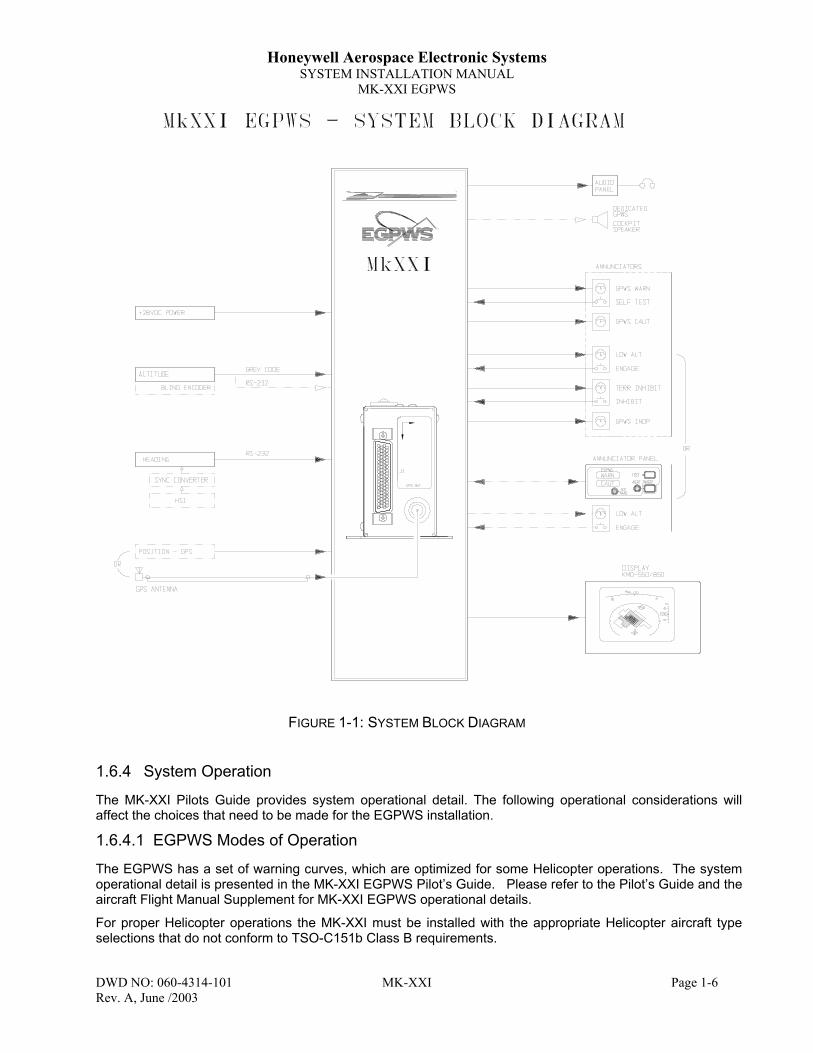
FIGURE 1-1: SYSTEM BLOCK DIAGRAM
1.6.4 System Operation
The MK-XXI Pilots Guide provides system operational detail. The following operational considerations willaffect the choices that need to be made for the EGPWS installation.
1.6.4.1 EGPWS Modes of Operation
The EGPWS has a set of warning curves, which are optimized for some Helicopter operations. The systemoperational detail is presented in the MK-XXI EGPWS Pilot’s Guide. Please refer to the Pilot’s Guide and theaircraft Flight Manual Supplement for MK-XXI EGPWS operational details.
For proper Helicopter operations the MK-XXI must be installed with the appropriate Helicopter aircraft typeselections that do not conform to TSO-C151b Class B requirements.
Honeywell Aerospace Electronic SystemsSYSTEM INSTALLATION MANUAL
MK-XXI EGPWS
DWD NO: 060-4314-101 MK-XXI Page 1-7Rev. A, June /2003
1.6.4.1.1 Helicopter Aircraft Type Selection
Two Helicopter aircraft type selections are available. One allows the system to start-up in default normalmode, the other is to start-up in default Low Altitude Mode. Normal and Low Altitude Modes are defined inthe MK-XXI Pilot’s Guide.
1.6.4.1.2 GPS Sensor
The MK-XXI contains an embedded GPS-XPRESS Card sensor (GPS receiver) that produces validatednavigational position data by continuous signal acquisition and tracking of the navigational satellite network.The GPS Sensor receives the C/A code signals transmitted by the satellite network on the L1 frequency of1575.42 MHz. The sensor has 8 signal processing channels allowing 8 satellites to be trackedsimultaneously. The GPS Sensor uses data in the satellites’ navigation messages to solve for latitude,longitude, altitude, horizontal velocity, vertical velocity and current UTC.
GPS Data can also be supplied via the ARINC 743, 743A and RS-232/422 interfaces.
1.6.4.2 Options
1.6.4.2.1 Display Option
TSO-C151b-class B does not require a display for terrain data, however, if at all possible, terrain data shouldbe displayed for the aircraft operator. The terrain display greatly improves situational awareness. TheEGPWS supports numerous displays including traditional Radar displays as well as some modernMultifunction Display Systems (MFDs).
Installations, which include a display, will also need to provide the EGPWS with range data via ARINC 429format.
1.6.4.2.2 Altitude Monitor Option
The MK-XXI EGPWS has the ability to monitor altitude sources and provide cautionary messages should analtitude source be suspected of being in error. This feature compares barometric altitude with GPS altitudeand generates a “Check Altitude” message when an error is detected. This is a highly recommended option,which can alert a pilot to problems such as a stuck altimeter or plugged static port. This option requires noadditional hardware and is enabled during the system installation by programming the configuration module.This feature can provide both audio and display messages.
1.6.4.2.3 Outside Air Temperature (OAT)
The MK-XXI EGPWS supports an interface to an OAT probe for aircraft operated in cold environments. Verycold air temperatures cause an increase in the density of the air mass and can result in barometric altimetererrors, both in sensitive altimeters/encoders and blind encoders. Aircraft normally operated in very coldclimates can benefit from the addition of an OAT probe interfaced to the EGPWS. If the aircraft is equippedwith an Air Data Computer, which outputs Digital data with Static Air Temperature on an ARINC 429 port, thiscan be used instead of an encoder and external OAT Probe. OAT and SAT label input selection isprogrammed into the configuration module during system installation.

Honeywell Aerospace Electronic SystemsSYSTEM INSTALLATION MANUAL
MK-XXI EGPWS
DWD NO: 060-4314-101 MK-XXI Page 1-8Rev. A, June /2003
1.7 Technical Characteristics
1.7.1 MK-XXI EGPWS InformationP/N 965-1227-003, -005
TSO Compliance: TSO-C151b Class B. See EnvironmentalCharacteristics listed in Section 9
Physical Dimensions: See Section 2.3 Equipment InstallationWeight: Less than 1.6 lbs. w/ mating connectorPower Requirements: 10 VDC - 32 VDC,
<1 Amp, up to 8.0 Watts dissipationTemperature Range -40°C to 55°CHumidity Range Tested to 85% RH for 48 HoursInstallation Space See Section 2.3 Equipment InstallationAltitude up to 55,000 feetCooling No forced cooling required
TABLE 1-2: MK-XXI UNIT TECHNICAL SPECIFICATIONS
1.7.2 MK-XXI Configuration Module Information
P/N 071-01710-0004, -0021TSO Compliance: TSO-C151b Class B. See Environmental
Characteristics listed in Section 9Weight: Less than 2 oz.Power Requirements: Provided by UnitTemperature Range -40°C to 55°CHumidity Range Tested to 85% RH for 48 HoursInstallation Location See Section 2.3 Equipment InstallationAltitude up to 55,000 feetCooling No forced cooling required
TABLE 1-3: MK-XXI CONFIGURATION MODULE SPECIFICATIONS
1.7.3 MK-XXI Regional Terrain Database Information
P/N 071-00182-0110, -0120…-0190TSO Compliance: TSO-C151b Class B. See Environmental
Characteristics listed in Section 9Weight: Less than 1 oz.Power Requirements: Provided by UnitTemperature Range -40°C to 55°CHumidity Range Tested to 85% RH for 48 HoursInstallation Location See Section 2.3 Equipment InstallationAltitude up to 55,000 feetCooling No forced cooling required
TABLE 1-4: MK-XXI REGIONAL TERRAIN DATABASE SPECIFICATIONS

Honeywell Aerospace Electronic SystemsSYSTEM INSTALLATION MANUAL
MK-XXI EGPWS
DWD NO: 060-4314-101 MK-XXI Page 1-9Rev. A, June /2003
1.8 Unit and Accessories SuppliedSome part numbers may not be currently available. Consult the current Honeywell catalog or contact yourHoneywell representative for equipment availability.
1.8.1 MK-XXI EGPWS Computer
Model Designation DescriptionManufacturers’ID Number
Bendix/KingPart Number
MK-XXI EGPWS EGPWS LRU 965-1227-005 066-01227-0205MK-XXI EGPWS EGPWS LRU 965-1227-003 066-01227-0101
Note: The MK-XXI must be ordered using the Bendix/King 066-01227-0101 part number.
1.8.2 MK-XXI EGPWS Configuration Module
Model Designation DescriptionManufacturers’ID Number
Bendix/KingPart Number
MK-XXI Config. Module Configuration Module 700-1710-021 071-01710-0021MK-XXI Config. Module Configuration Module 700-1710-004 071-01710-0004
Note: The MK-XXI configuration module must be ordered using the Bendix/King 071-01710-00XXpart number. Honeywell highly recommends the –0021 configuration module.
1.8.3 MK-XXI EGPWS Install Kit
Model Designation DescriptionManufacturers’ID Number
Bendix/KingPart Number
MK-XXI Install Kit(Same as KGP 560 Install Kit)
Installation Kit N/A 050-03621-0000
MK-XXI (KGP 560) Installation Kit (050-03621-0000) contents include:P/N Description030-01157-0011 SOCKET CRMP 20G (Qty. 9)030-01171-0000 CONN SUB-D HSG 9S (FEMALE PINS)033-00230-0000 TELEPHONE JACK, 4 CONDUCTOR030-01451-0000 CONTACT SOCKET (Qty. 78)030-02351-0004 HOOD/LVR ASSY030-03296-0001 HI DENSITY SUBD78P030-00134-0001 CONN COAX RT ANGLE
Note: The KGP-560 is a Honeywell GA-EGPWS for small fixed wing aircraft. The KGP-560 and theMK-XXI use the same installation hardware (kit).

Honeywell Aerospace Electronic SystemsSYSTEM INSTALLATION MANUAL
MK-XXI EGPWS
DWD NO: 060-4314-101 MK-XXI Page 1-10Rev. A, June /2003
1.8.4 MK-XXI EGPWS Regional Terrain Database
Model Designation DescriptionManufacturers’ID Number
Bendix/KingPart Number
NORTH AMERICA DATABASEfor MK-XXI EGPWS
North America Database 4XXNAM (latestrelease)
071-00182-0110
SOUTH AMERICA DATABASEfor MK-XXI EGPWS
South America Database 4XXSAM (latestrelease)
071-00182-0120
EUROPE DATABASE for MK-XXIEGPWS
Europe Database 4XXEUR (latestrelease)
071-00182-0130
EASTERN EUROPE DATABASEfor MK-XXI EGPWS
Eastern Europe Database 4XXEEU (latestrelease)
071-00182-0140
AFRICA DATABASE for MK-XXIEGPWS
Africa Database 4XXAFR (latestrelease)
071-00182-0150
PACIFIC DATABASE for MK-XXIEGPWS
Pacific Database 4XXPAC (latestrelease)
071-00182-0160
ASIA DATABASE for MK-XXIEGPWS
Asia Database 4XXASI (latestrelease)
071-00182-0170
SOUTH PACIFIC DATABASE forMK-XXI EGPWS
South Pacific Database 4XXSPA (latestrelease)
071-00182-0180
MIDDLE EAST DATABASE forMK-XXI EGPWS
Middle East Database 4XXMES (latestrelease)
071-00182-0190
TABLE 1-5: MK-XXI REGIONAL TERRAIN DATABASES
Note: The appropriate terrain data base card must be ordered for the region in which the aircraft isto be operated. When ordering the terrain database, the latest database available is provided.

Honeywell Aerospace Electronic SystemsSYSTEM INSTALLATION MANUAL
MK-XXI EGPWS
DWD NO: 060-4314-101 MK-XXI Page 1-11Rev. A, June /2003
1.9 Accessories Required But Not Supplied
1.9.1 Cable and WireP/N DescriptionMIL-W-22759/16 WIRE (OR EQUIVALENT)MIL-C-27500 SHIELDED WIRE (OR EQUIVALENT)RG-10599 SHIELDED WIREM17/176-00002 SHIELDED WIREM17/158-RG400 COAXIAL CABLE (OR EQUIVALENT)
1.10 Optional Accessories Not Supplied
1.10.1 Optional GPS Antenna & GPS Antenna Installation KitP/N Description071-01553-0200 KA 92 GPS Antenna (TSO C129)050-03318-0000 KA 92 GPS Antenna Installation Kit
Note: Please see Section 2.3.6 for GPS Antenna installation considerations.
KA 92 Installation Kit (050-03318-0000) contents include:
P/N Description030-00134-0001 CONNECTOR, TNC RT ANGLE047-10735-0002 BACKPLATE, ANTENNA089-05909-0012 SCR PHP 8-32X3/4 (Qty 4)187-01831-0000 ANTENNA GASKET155-06019-0000 INSTALL DWG KA 92
1.10.2 Optional Temperature Probe
The EGPWS is capable of interfacing directly to a standard 500-ohm temperature probe for aircraft operatedin cold environments. Very cold air temperatures cause an increase in the density of the air mass and canresult in barometric altimeter errors, both in sensitive altimeters/encoders and blind encoders. Aircraftnormally operated in very cold climates can benefit from the addition of an OAT probe interfaced to theEGPWS
Note: The MK-XXI EGPWS will accept temperature data from a Digital Air Data Computer given thereis a Static Air Temperature (SAT) label present on the bus.
P/N Description050-03610-0002 TEMP PROBE KIT
Temp Probe Kit (050-03610-0002) contents include:P/N Description010-00068-0016 CRIMP TRML 6S M3.5090-01034-0001 MOUNTING PLATE, TEMP. PROBE137-00042-0001 TEMP PROBE, 500 OHMMS3106E12S-3S STRAIGHT PLUG, 2 PIN

Honeywell Aerospace Electronic SystemsSYSTEM INSTALLATION MANUAL
MK-XXI EGPWS
DWD NO: 060-4314-101 MK-XXI Page 1-12Rev. A, June /2003
1.10.3 Annunciators & Switches
Various light & switch options may be used when installing the MK-XXI EGPWS system. Annunciator,switches and compact annunciator/switch panels are available from other vendors.
The optional LOW ALT annunciator (lamp/switch) is not included in the sections below. It is an optional yetrecommended item for all MK-XXI installations. The LOW ALT annunciator may be purchased separatelyfrom numerous annunciator/kit vendors, see Section 1.10.3.3 for additional annunciator vendors.
1.10.3.1 Optional Annunciator Install Kit
Specification Drawing 031-00810-01 defines the sub-assembly parts, spacers to cover different panelthickness and artwork definitions for associated items.
P/N Description050-03610-0000 ANNUNCIATOR INSTALL KIT
Annunciator Install Kit (050-03610-0000) contents include:P/N Description030-01459-0001 CONTACT SKT 20AWG (Qty 20)030-03430-1001 CONN. RECT. SKT. MODULE, SIZE 22, LMD SERIES030-03430-1006 CONN. RECT. CONT. SKT. SIZE 22, LMD SERIES (Qty 16)030-03430-3001 CONN. RECT. DIODE MDL, 8 DISCRETE, SIZE 22030-03430-6002 CONN. RECT. HSG, SPLICE, TOOL-LESS, LMS SERIES031-00791-0001 SWITCH PUSH MOM 1 POLE031-00810-0001 INDICATOR, COMMON GND (Qty 2)031-00810-0003 SWITCH BODY, ALT, COMMON GND031-00810-0022 MOUNTING SLEEVE/CONNECTOR, .109 IN. (Qty 3)(See the Note below)031-00810-0100 LAMP CAPSULE (TERR/TERR)031-00810-0101 LAMP CAPSULE (TERR. INHIBIT/OFF/ON)031-00810-0103 LAMP CAPSULE (TERRAIN N/A)
Note: The following mounting sleeve/spacer/connector assemblies are not included in this kit but areavailable to accommodate instrument panel thickness as follows:
P/N Description031-00810-0020 0.022 to 0.042 Inches031-00810-0021 0.053 to 0.073 Inches031-00810-0023 0.115 to 0.135 Inches031-00810-0024 0.180 to 0.200 Inches031-00810-0025 0.240 to 0.260 Inches
1.10.3.2 Optional Terrain Switching KitP/N Description050-03610-0001 TERRAIN SWITCHING KIT
Terrain Switching Kit (050-03610-0001) contents include:P/N Description030-01459-0001 CONTACT SKT 20AWG (Qty 7)031-00810-0002 SWITCH BODY, MOM, COMMON GND031-00810-0022 MOUNTING SLEEVE/CONNECTOR, .109 IN.(Please see the Note in Section 1.10.2 for additional Sleeve/Connector sizes)031-00810-0102 LAMP CAPSULE (RADAR, IND/RDR/TERR)032-00153-0001 4 POLE RELAY033-00235-0001 RELAY SOCKET131-00750-0023 RES CF 75 QW 5%

Honeywell Aerospace Electronic SystemsSYSTEM INSTALLATION MANUAL
MK-XXI EGPWS
DWD NO: 060-4314-101 MK-XXI Page 1-13Rev. A, June /2003
1.10.3.3 Other Vendors
The following information on compact annunciator/switch panels is supplied for the convenience to theEGPWS installers. The manufacturer provides complete details necessary to install these parts listed here.
• West Coast Specialties' Annunciator Panel 90-44802-1. Contact West Coast Specialties in Preston, WAat 425/222-3118.
• Mid-Continent Instrument's MD 41-1208 & MD 41-1308. Contact Mid-Continent in Wichita, KS at316/630-0101 or in Van Nuys, CA at 818/786-0300 or at http://www.mcico.com
• Edmo Distributing Inc., Spokane, Wa. Phone: 800-235-3300
1.10.4 PC Diagnostic Connection Components
To provide the necessary serial PC Diagnostic connection, the female DB-09 D-Sub-Miniature connectorincluded in the MK-XXI Installation Kit can be wired to the EGPWS as shown in Figure 3-3. Alternatively, thePC Data Loader Kit used with the KLN 90B can be installed and used for the serial Diagnostic Port Interfacewith a PC. See the KLN 90B Install Manual for wiring the Data Loader connections.
P/N Description050-03213-0000 PC DATA LOADER KIT
PC Data Loader Kit (050-03213-0000) contents include:P/N Description030-03223-0000 ADAPTER RS-232 9-25155-02794-0001 COMPUTER CBL ASSY
1.10.5 Special Tools Required
The following special tools (or their equivalent) are necessary for working with the P1 connector. Only oneitem from each category is needed.
1.10.5.1 Crimping Tool – P1Description Vendor Part NumberHand Crimping Tool MIL M22520/2-1Hand Crimping Tool Positronic Industries 9507Hand Crimping Tool Daniels AFM8
1.10.5.2 Contact Positioner – P1Description Vendor Part NumberContact Positioner MIL M22520/2-06Contact Positioner Positronic Industries 9502-3Contact Positioner Daniels K41
1.10.5.3 Insertion/Removal Tool – P1Description Vendor Part NumberInsertion/Removal Tool MIL M81969/1-04

Honeywell Aerospace Electronic SystemsSYSTEM INSTALLATION MANUAL
MK-XXI EGPWS
DWD NO: 060-4314-101 MK-XXI Page 1-14Rev. A, June /2003
1.11 Regional Terrain Database UpdatesThe proper Regional Terrain Database for where the aircraft is to be operated is required to be installed in theMK-XXI EGPWS LRU. Regional Terrain databases can be ordered for card updates or another region bycontacting:
Honeywell International Inc.
Aerospace Electronic Systems
One Technology Center
23500 West 105th Street
Olathe, Kansas 66061 USA
Attn: Navigation Services MS-66
Telephone: (800) 247-0230 within the United States or Canada
(913) 712-3145 outside of the United States or Canada
Fax: (913) 712-3904
e-mail: [email protected]
See Section 5.3 for Regional Terrain Database installation and verification procedures.

Honeywell Aerospace Electronic SystemsSYSTEM INSTALLATION MANUAL
MK-XXI EGPWS
DWD NO: 060-4314-101 MK-XXI Page 1-1Rev. A, June /2003
2 SECTION II – INSTALLATION
2.1 IntroductionThis section contains suggestions and factors to consider before installing the MK-XXI System. This sectionincludes the required equipment installation consideration and mechanical installation drawings and will give abrief description of the procedures for the initial installation of the MK-XXI into an aircraft. The installationparts are listed in Section 1. Close adherence to these suggestions will assure satisfactory performance fromthe equipment.
Note: The conditions and tests performed on the system components are minimum performancestandards. It is the responsibility of those desiring to install the MK-XXI either on or within aspecific type or class of aircraft to determine that the aircraft installation conditions are withinstandards.
2.2 Unpacking And Inspecting EquipmentExercise caution when unpacking equipment. Perform a visual inspection of the unit for evidence of damageincurred during shipment. If a damage claim must be filed, save the shipping container and all the packingmaterials to substantiate your claim. The claim should be filed as soon as possible. The shipping containerand all packing material should be retained in the event that storage or reshipment of the equipment isnecessary.
Multiple components are typically shipped with each MK-XXI unit including the configuration module,installation kit, regional database and required documentation. Ensure all components are removed from theshipping container.
2.3 Equipment Installation Considerations
2.3.1 General Considerations
The equipment should be installed in the aircraft in a manner consistent with acceptable workmanship andengineering practices, and in accordance with the instructions set forth in this publication. To ensure thesystem has been properly and safely installed in the aircraft, the installer should make a thorough visualinspection and conduct an overall operational check of the system, on the ground, prior to flight.
Caution: After installation of the cabling and before installation of the equipment, a check should bemade with the aircraft primary power supplied to the mounting connector, to ensure thatpower is applied only to the pins specified in the interwiring diagrams, per instruction inSection 5.2.
The MK-XXI System installation will conform to standards designated by the customer, installing agency, andexisting conditions as to the unit location and type of installation. However, the following suggestions shouldbe carefully considered before installing your system.
2.3.2 Avionics Cooling Considerations
The most important contribution to improved reliability of all avionics equipment is to limit the maximumoperating temperature of the individual unit, whether panel mounted or remote mounted. While modern circuitdesigns consume less total energy, the heat dissipated per unit volume (Watts/cubic inch) remains much thesame due to contemporary high density packaging techniques. While each individual unit may not requireforced air cooling, the combined heat generated by several units operating in a typical panel or rack cansignificantly degrade the reliability of the equipment. Consequently, the importance of providing force aircooling to avionics equipment mounted in either a panel or rack is essential to the life span of the equipment.Adequate provisions for cooling should be incorporated during the installation.

Honeywell Aerospace Electronic SystemsSYSTEM INSTALLATION MANUAL
MK-XXI EGPWS
DWD NO: 060-4314-101 MK-XXI Page 1-2Rev. A, June /2003
2.3.3 MK-XXI Installation Considerations
The following paragraphs contain information pertaining to the installation of the MK-XXI System, includingconsiderations and instructions concerning the location and mounting of the equipment.
2.3.3.1 MK-XXI Cooling Considerations
The MK-XXI requires no external forced air-cooling and consumes very little power.
2.3.3.2 Installation/Location Considerations
The typical EGPWS will need to interface to the aircraft audio system, aircraft DC power, panel mountedwarning lamps and switches, a source of barometric altitude (usually an encoding altimeter or blind encoder),a GPS antenna, and a panel mounted display. The interface to the GPS antenna is an important item. SeeSection 2.3.6 for details.
Consideration should be given to the following items affected by the choice of installation location within theaircraft:
A. Environmental Considerations
B. Ease of Interface to aircraft systems
C. GPS Antenna location and coaxial cable length
D. Ability to extract and insert new terrain/obstacle Databases supplied on a CompactFlash Card asthe regional terrain database CompactFlash card may be updated periodically.
If possible, install the MK-XXI in an easily accessible dry, temperature-controlled area such as within thepassenger compartment of the aircraft. Standard avionics bays are acceptable as well.
If possible, the MK-XXI should NOT be located in close proximity to equipment that produce considerableheat.
Locations, which require disassembly of the aircraft to gain access, are less desirable.
Any location that is exposed to moisture and/or temperature extremes should be avoided.
Select a mounting location that allows sufficient clearance at the front of the unit for connectors and cables.
Do not bundle data lines or antenna cable with any power cables.
No more than 8.0dB-signal loss is allowed in the GPS antenna cable run. See to Section 2.3.6.
Mount the unit to provide good electrical bonding to airframe ground. Lightning strike protection and RFsusceptibility and emission characteristics depend on good electrical grounding of the unit and cable shieldreturns.
Note: The MK-XXI will need to interface to the aircraft audio system, aircraft DC power, panelmounted warning lamps and switches, a source of barometric altitude (usually an encodingaltimeter or blind encoder), a GPS antenna (or other position source) and a panel mounteddisplay.
If possible, clearance to the top of the MK-XXI should be provided to facilitate removal and installation of theregional terrain database CompactFlash card. The terrain database card is removed and installed with powerNOT applied to the system. The MK-XXI may be removed from the aircraft to extract and install databasecards if the mounting location does not provide enough clearance.
Installing the Regional Terrain Database is accomplished by:Moving the cover over the CompactFlash card out of the way.
Pressing the flash card ejector button located within the unit.
Removing the old flash card.

Honeywell Aerospace Electronic SystemsSYSTEM INSTALLATION MANUAL
MK-XXI EGPWS
DWD NO: 060-4314-101 MK-XXI Page 1-3Rev. A, June /2003
Inserting the new flash card and replacing the cover.
If possible, mount the MK-XXI such that the above can be accomplished without requiring disassembly of theaircraft or removal of the MK-XXI.
The EGPWS provides a single 600 ohm audio output which should be connected to a un-switched/un-mutedauxiliary audio input on the aircraft’s audio control panel. Programming the configuration module sets theaudio output power level.
2.3.3.3 Annunciator Lamp Considerations
The MK-XXI can drive seven lamps and accepts input from four switches. The lamps should be identified as:FUNCTION COLOR LEGENDWarning Red EGPWS / TERR / WARNCaution Amber EGPWS / TERR / CAUTTerrain INOP/Not Available Amber TERR INOP / NOT AVAIL /
TERR N/ALow Alt On Green LOW ALTTerrain On Green TERRTerrain Inhibit On Green / Amber TERR OR ALERT INHIB
TABLE 2-1: MK-XXI LAMP/SWITCH LEGENDS
The caution and warning lamps should be located in the pilot’s primary visual field of view. Various light &switch options may be used when installing the MK-XXI EGPWS system. Annunciator, switches and compactannunciator/switch panels are available from several vendors. The complete data to install this equipment isprovided by the manufacturer.
2.3.3.4 Equipment Installation ProcedureA. Place the unit into aircraft and secure it. (Please refer to Section 5 for detailed installationsequence and preparation)B. Attach the harness to the front mating connector of the unit.C. Attach antenna coax cable J2 to the front of the unit. (If the internal GPS receiver is to be used)
2.3.3.5 Mechanical Installation Instructions
Make sure that the unit is installed in a location where the ambient temperatures are between–67 DEG F to + 131 DEG F (-55 DEG C to +55 DEG C). The EGPWS Computer is surface/rigidly mountedand does not require a mounting rack. Allow at least one inch of free air space around the top and rear of theunit and at least ½ inch along each side. Allow adequate space for the installation of cables and connectors.Consideration must be taken for the removal and installation of the data base flash card located in the top ofthe computer. The mounting hole pattern and dimensions may be obtained from the following figure. Mark,punch and drill the mounting holes. Care must be taken to avoid damage to adjacent equipment or cables.Mount the unit to provide good electrical bonding to the airframe ground.

Honeywell Aerospace Electronic SystemsSYSTEM INSTALLATION MANUAL
MK-XXI EGPWS
DWD NO: 060-4314-101 MK-XXI Page 1-4Rev. A, June /2003
2.3.3.5.1 Outline Drawing– MK-XXI EGPWC (with GPS)
FIGURE 2-1: EGPWS COMPUTER OUTLINE DRAWING

Honeywell Aerospace Electronic SystemsSYSTEM INSTALLATION MANUAL
MK-XXI EGPWS
DWD NO: 060-4314-101 MK-XXI Page 1-5Rev. A, June /2003
2.3.3.6 EGPWS Computer Installation Mounting
MK-XXI mounting hole patterns and dimensions required for the installation are depicted in the followingdrawing:
FIGURE 2-2: STANDARD MOUNTING
2.3.4 Configuration Module Installation
The MK-XXI system requires a Configuration Module for storage of required operational parameters thatinclude the aircraft interface and functionality definitions specific to the installed aircraft. Requiredprogramming of the Configuration Module is detailed in Section 5.4.4 of this manual.
2.3.4.1 Installation Considerations
A. The Configuration Module must be mounted to the mating connector. Make sure to leave adequate spaceto mount the Configuration Module when installing the Unit.
B. Make sure that the unit is installed in a location where the ambient temperatures are-67°F to +158°F (-50°C to +70°C).

Honeywell Aerospace Electronic SystemsSYSTEM INSTALLATION MANUAL
MK-XXI EGPWS
DWD NO: 060-4314-101 MK-XXI Page 1-6Rev. A, June /2003
2.3.4.2 Installation Procedure
A. Install the Configuration Module onto the connector. Refer to the following procedures and Figure 2-9.
B. Tighten the mounting screws to secure the Configuration Module.
2.3.5 Configuration Module Installation Assembly
The purpose of this procedure is to give assembly sequence and information for assembly of the P1Connector, Backshell and the installation of the EGPWS - Configuration Module.
REQUIRED: Two items as follows:
1. MK-XXI Installation Kit (Honeywell P/N 050-03621-0000)2. Configuration Module (Honeywell P/N 071-01710-0004 or -0021)
ITEM 2 DESCRIPTION:
See Section 1.8.3 for MK-XXI Installation Kit contents.
INSTALLATION ASSEMBLY SEQUENCE
STEP 1 Install all EGPWS system aircraft wiring to this connector using items the Crimp Contacts andConnector. See the following figures.
FIGURE 2-3: CONNECTOR REAR VIEW
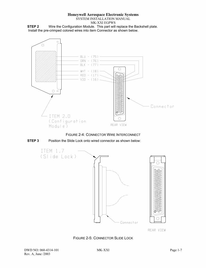
Honeywell Aerospace Electronic SystemsSYSTEM INSTALLATION MANUAL
MK-XXI EGPWS
DWD NO: 060-4314-101 MK-XXI Page 1-7Rev. A, June /2003
STEP 2 Wire the Configuration Module. This part will replace the Backshell plate. Install the pre-crimped colored wires into item Connector as shown below.
FIGURE 2-4: CONNECTOR WIRE INTERCONNECT
STEP 3 Position the Slide Lock onto wired connector as shown below:
FIGURE 2-5: CONNECTOR SLIDE LOCK

Honeywell Aerospace Electronic SystemsSYSTEM INSTALLATION MANUAL
MK-XXI EGPWS
DWD NO: 060-4314-101 MK-XXI Page 1-8Rev. A, June /2003
STEP 4 Install the backshell housing onto connector using the Screws as shown below:
FIGURE 2-6: CONNECTOR BACKSHELL CONNECTION
STEP 5 Install the Spring Clip as shown below:
FIGURE 2-7: CONNECTOR SPRING CLIP

Honeywell Aerospace Electronic SystemsSYSTEM INSTALLATION MANUAL
MK-XXI EGPWS
DWD NO: 060-4314-101 MK-XXI Page 1-9Rev. A, June /2003
STEP 6 Organize and dress wiring exiting from backshell. Route Configuration Module wires exitingfrom connector, then coil as shown in the next figure. Install the Cable Clamp as shown. Do nottighten screws yet.
FIGURE 2-8: CONNECTOR CONFIGURATION MOUNT
STEP 7 Secure Configuration Module to connector assembly using the Screws as shown below.Tighten Cable Clamp screws as required.
FIGURE 2-9: FRONT CONNECTOR WITH CONFIGURATION MODULE

Honeywell Aerospace Electronic SystemsSYSTEM INSTALLATION MANUAL
MK-XXI EGPWS
DWD NO: 060-4314-101 MK-XXI Page 1-10Rev. A, June /2003
2.3.6 GPS Antenna Installation
The EGPWS optionally uses an external GPS antenna (Honeywell model no. KA 92). Detailed installationinstructions for this antenna are available in the Honeywell KLN series and GNS-XLS series SystemInstallation Manuals. Please refer to these documents for this data.
2.3.7 Temperature Probe
The EGPWS can be interfaced to a standard 500 Ohm Outside Air Temperature probe. See Section 1 forpart number information.
2.3.8 Display
The EGPWS can be interfaced to numerous displays. Refer to Section 11.3 in this document for a list ofsupported displays.
2.3.9 Installation Constraints
The TSO C151b Class B identifies the minimum performance standards, tests, and other conditionsapplicable for issuance of design and production approval of the MK-XXI. The TSO does not specificallyidentify acceptable conditions for installation of the system. This systems installation manual defines theacceptable installation conditions that must be met. Aircraft specific environmental and functionalcompatibility has been addressed during the creation of this document.

Honeywell Aerospace Electronic SystemsSYSTEM INSTALLATION MANUAL
MK-XXI EGPWS
DWD NO: 060-4314-101 MK-XXI Page 1-11Rev. A, June /2003
3 SECTION III – ELECTRICAL INTERCONNECTS
3.1 IntroductionThis section contains the appropriate electrical interconnect information and details necessary for systemplanning and design of the MK-XXI EGPWS installation. You will find information relative to the MK-XXIsystem requirement options available to the system planner and the electrical characteristics of the variousinterfaces. You will also find pin lists and interconnect diagrams in this section.
Section 3 contains interconnect diagrams, electrical interface information and pin assignments for the MK-XXIsystem. Refer to Figure 3-3 for a typical MK-XXI system interconnect diagram. There are several interconnectdrawings for typical equipment that can interface with the MK-XXI included.
The installing agency may contact Honeywell Product Support at (913) 782-0600 for information regarding thecompatibility of equipment not listed in this manual. Normal business hours are 8:00 AM to 5:00 PM CentralTime, Monday through Friday. Also contact manufacturer of specific equipment for compatibility.
3.2 PurposeDetailed information necessary for system planning and designing the electrical portion of this installation isdescribed in this section.
3.3 Applicable Part Numbers Subsection DescriptionInformation given in this section pertains only to the MK-XXI System with part numbers shown in Section 1.6.See Section 1 for complete part number descriptions and ordering information.
3.4 Requirements and Limitations Subsection Description.Operational requirements or constraints relating to the interface are described in this section. Widely followedregulatory requirements may also be described here. Regionally enforced requirements vary greatly andadherence to them remains the responsibility of the installing agency.
3.5 Electrical Characteristics Subsection Description.The electrical characteristics and format of the interface signals are described in this section. Any partnumber specific differences in signal format are also described here. Overlined pin names generally indicateactive low signals, although the absence of an overline does not necessarily indicate an active high signal.

Honeywell Aerospace Electronic SystemsSYSTEM INSTALLATION MANUAL
MK-XXI EGPWS
DWD NO: 060-4314-101 MK-XXI Page 1-12Rev. A, June /2003
3.6 Interface Subsection DescriptionThe harness techniques for shielding and shield termination described in this manual are identical to thosespecified for the test harness used during HIRF and Lightning testing. Adherence to the information in thismanual is essential in establishing an installation environment equivalent to the test environment used duringHIRF and Lightning testing.
Should grounding the shields, as shown in the interconnect diagrams, cause unacceptable interference due tonoise sources on the aircraft, double shielded wire may be substituted for single shielded wire shown in thismanual. The outer shield must be grounded at both ends to comply with HIRF and Lightning requirements.The inner shield may then be grounded at a single end to protect against the aircraft noise source. Normallythe inner shield is grounded at the source end of the signal carried by the wire. Planning to install doubleshielded wire for low level signals known to have a history of interference may be easier than later adding thedouble shielded wire into the aircraft harness.
3.7 Installation ConstraintsThe TSO-C151b Class B identifies the minimum performance standards, tests, and other conditionsapplicable for issuance of design and production approval of the MK-XXI. The TSO does not specificallyidentify acceptable conditions for installation of the system. This systems installation manual defines theacceptable installation conditions that must be met. Aircraft specific environmental and functionalcompatibility has been addressed during the creation of this document.
3.8 Planning Considerations – Description of Features and OptionsThe following features and options need special consideration before installation to properly setup the aircraftconfiguration.
3.8.1 Encoding Altimeters / Blind Encoders / Digital Air Data Computers (DADC)
The EGPWS computer can be configured to accept barometric altitude data from either a Digital Air DataComputer via a digital interface, or from an encoding altimeter or blind encoder. In all cases, the altitudesource must be referenced to 29.92 in. Hg. and not be adjustable by the flight crew. General Aviationinstallations will typically use an encoding altimeter or blind encoder. Honeywell has tested various encodingaltimeters and blind encoders for compatibility with the EGPWS computer. These units are listed in Section11.1 of this document.
In all cases, when interfacing the EGPWS computer to encoding altimeters or blind encoders, the encodersmust have power applied at all times when the EGPWS computer is in use and the altitude common(strobe) line must be grounded. If you are interfacing to an existing encoder which is providing GillhamAltitude data to a transponder, make absolutely certain that the common line is not being driven by thetransponder.

Honeywell Aerospace Electronic SystemsSYSTEM INSTALLATION MANUAL
MK-XXI EGPWS
DWD NO: 060-4314-101 MK-XXI Page 1-13Rev. A, June /2003
3.8.1.1 Altitude Monitor Option
The EGPWS has the ability to monitor altitude sources and provide cautionary messages should an altitudesource be suspected of being in error. This feature compares barometric altitude with GPS altitude andgenerates an aural and (if a terrain display is installed) a visual “Check Altitude” message when an error isdetected. This is a highly recommended option, which can alert a pilot to problems such as a stuck altimeteror plugged static port.
This option requires no additional hardware and is enabled during system installation by programming theconfiguration module. If selected, the EGPWS computer has the ability to warn the pilot with both aural anddisplay messages of possible altimeter problems.
With this option enabled, several possible combinations of fault detection are possible. Refer to Section 4 inthis document for configuration details.
In addition to recommending the Altitude Monitor Option, Honeywell highly recommends, if the display iscapable, to enable the display of Geometric Altitude. Please refer to Section 7.2.4, for further information.
3.8.1.2 Encoding Altimeters That Are The Pilot’s Primary Altitude Reference
Using the pilot’s encoding altimeter as the altitude source for the EGPWS computer will allow the system toalert the pilot to a stuck altimeter or a plugged static system. In some installations the pilot’s encodingaltimeter will also be wired to the aircraft’s transponder. In this situation, a stuck altimeter or plugged staticsystem can result in air traffic control and the pilot both believing an erroneous altitude. Upon detecting asignificant long-term error between GPS altitude and barometric altitude the EGPWS would generate a“Check Altitude” message. This arrangement provides the best detection of large serious barometricaltitude errors.
3.8.1.3 Aircraft Equipped With A Blind Encoder.
Using an existing blind encoder as the source for the EGPWS will allow the system to detect a failed blindencoder or plugged static system. If the pilot’s altimeter fails, the EGPWS will be unable to detect thisproblem. This arrangement allows the EGPWS to monitor the altitude source, which is reported to ATC.
3.8.1.4 A Dedicated Blind Encoder
In some aircraft, it may be desirable, or necessary to add a dedicated blind encoder specifically as an altitudesource for the EGPWS. Since this dedicated encoder shares the aircraft static system, the EGPWS will beable to detect a plugged static system and any failure of its dedicated encoder. It will not be able to detect afailure of the pilot’s altimeter or the encoder, which is reporting altitude to ATC. Basically, this arrangementwould provide additional safety in its ability to detect static system problems.
3.8.2 Cockpit Lamps & Switches
The EGPWS drives lamps and accepts inputs from switches. The lamps and switches must be identified asdetailed in Section 1.10.3. Various light & switch options may be used when installing the MK-XXI EGPWSsystem. Annunciator, switches and compact annunciator panels are available from several vendors. Thesome data to install these panels is included in the Interconnect Diagrams but generally the installation detailsare provide by the manufacturer.
Certain displays may also support the display and actuation of Lamp and Switches. Refer to the installationinformation with the display and MK-XXI configuration information in Section 4.3.1.5.

Honeywell Aerospace Electronic SystemsSYSTEM INSTALLATION MANUAL
MK-XXI EGPWS
DWD NO: 060-4314-101 MK-XXI Page 1-14Rev. A, June /2003
3.8.3 Audio
The EGPWS provides a single 600-Ohm audio output to be connected to the aircraft’s audio system using anun-switched un-muted warning input. Programming the configuration module sets the audio output powerlevel. See Section 3.8.3 for interphone audio output information.
3.8.4 GPS Antenna
To use the internal GPS receiver (card) the EGPWS must be interfaced to an external GPS antenna.Detailed installation instructions for the Bendix/King model no. KA 91 or KA 92 antenna is available in theHoneywell KLN series and GNS-XLS series System Installation Manuals. Please refer to these documentsfor this data.
3.8.5 Outside Air Temperature (OAT) Option
The EGPWS can be interfaced to a standard 500 Ohm Outside Air Temperature probe. The use of an OATwill improve altitude accuracy when the aircraft is operated at cold temperatures. Aircraft, which are routinelyflown in cold climates, at altitudes that place the aircraft close to terrain, will benefit from the use of an OAT.High performance aircraft, which are flown at high, (cold) altitudes; high above precipitous terrain are less of aconcern. In all cases, system accuracy is improved by the addition of an OAT. As a general rule, if theaircraft is operated in a geographic area where temperatures are routinely at or below 0° C a temperatureprobe should be considered.
The EGPWS supports an optional OAT probe for aircraft operated in cold environments. Operationalenvironments where the OAT probe is needed to supplement the Geometric Altitude calculation are whenoperating -15°C below ISA. This is typically environments of 0°C and below. Since the DOD GPS selectiveavailability has been turned off the need for the OAT is further diminished.
Very cold air temperatures cause an increase in the density of the air mass and can result in barometricaltimeter errors, both in sensitive altimeters/encoders and blind encoders. Aircraft normally operated in verycold climates can benefit from the addition of an OAT probe interfaced to the EGPWS. If the aircraft isequipped with an Air Data Computer which outputs Digital data with Corrected Altitude on an ARINC 429 port,this can be used instead of an encoder and external OAT probe. OAT options are programmed into theconfiguration module during system installation.
3.8.6 Display Option
The EGPWS can be interfaced to numerous displays. Choosing to display this terrain data is the mostimportant enhancement to situational awareness. This is especially true for lower performance aircraft. Inaddition to showing terrain ahead of the aircraft, (depending on configuration settings and display types) theEGPWS can display Geometric Altutide (GSL/MSL altitude), Magnetic Track, Range in NM, and theelevations of the highest and lowest terrain features shown on the display (`Peaks’). The color and intensityof the terrain displayed, instantly alerts the pilot to areas of dangerous terrain and conversely to areas of lessprecipitous terrain.
TSO-C151b Class B does not require a display for terrain data, however, if at all possible, terrain data shouldbe displayed for the aircraft operator. The terrain display greatly improves situational awareness. TheEGPWS supports numerous displays including traditional Radar displays as well as modern MFD’s.Installations, which include a display, will also need to provide the EGPWS with range data via ARINC 429format.
Refer to Section 11.3 of this manual for a list of supported display types.

Honeywell Aerospace Electronic SystemsSYSTEM INSTALLATION MANUAL
MK-XXI EGPWS
DWD NO: 060-4314-101 MK-XXI Page 1-15Rev. A, June /2003
3.9 General Electrical Interface Information
3.9.1 Introduction
The EGPWS provides external interfaces for integration into aircraft systems and to support maintenancefunctions. The interfaces are made via the front panel D sub-miniature connector. The MK-XXI also has aTNC coaxial connector on the front panel to provide for a GPS antenna connection. The following sectionsdescribe each of the external interfaces contained in these physical interfaces. See Section 4.2 for currentinterface configuration capabilities of the EGPWS.
3.9.2 Signal Interfaces
This section identifies and describes the general electrical characteristics and number of each interface typelocated in the front aircraft interface connectors. Front aircraft interface connector is defined as J1 (78contacts) and J2 (GPS antenna). Section 0 identifies the connector pin assignments. The signal mnemonicfor each signal is included in the following paragraphs.
No two-wire absolute AC signals are available. All analog inputs provide broken wire detection on all inputsignal legs. Unless otherwise stated, the “Maximum reverse fault current” is defined as the current resultingfrom an internal component failure, with the input signal at zero volts.
3.9.2.1 Grounds
3.9.2.1.1 Chassis Ground
Used for redundant metal connection. These pins are internally connected to DC Ground (see paragraph3.9.2.1.2) and could be used as a signal return.
Pin Assignment (Signal Mnemonic): J1-2, J1-29, J1-38, J1-46,J1-58, J1-62, J1-70, J1-75
(CHASSIS GND)
3.9.2.1.2 DC Ground
For discrete inputs and lamp driver outputs. This pin is internally connected to Chassis Ground (seeparagraph 3.9.2.1.1).
Pin Assignment (Signal Mnemonic): (same as +28 VDC Return) J1-21 (AIRCRAFT PWR RET)
Note: All analog signals are differential input.
3.9.2.2 Primary Power InputNominal Input 28 VDC 14 VDCNormal Voltage Range 22.0 to 30.3 VDC 11.0 to 15.1 VDCNormal Surge Voltage Range 15 – 40VDC (30 msec) 7.5 – 20VDC (30 msec)Abnormal Voltage Range 20.5 to 32.2 VDC 10.0 to 16.1 VDCAbnormal Surge VoltageRange
37.8 VDC (1sec);46.3 VDC (100 msec)
18.9 VDC (1sec);23.1 VDC (100 msec)
Normal Frequency Range not applicable not applicableFrequency Transients not applicable not applicable

Honeywell Aerospace Electronic SystemsSYSTEM INSTALLATION MANUAL
MK-XXI EGPWS
DWD NO: 060-4314-101 MK-XXI Page 1-16Rev. A, June /2003
Power Requirements 5 Watts – No Warnings5.5 Watts with warning voiceover 600 Ω speaker+2.5 Watts with Internal GPS(includes antenna power)1
5 Watts – No Warnings5.5 Watts with warning voiceover 600 Ω speaker+2.5 Watts with Internal GPS(includes antenna power)1
Recommended Power ControlDevice
1 Amp delayed action circuitbreaker.
1 Amp delayed action circuitbreaker.
Pin Assignment (Signal Mnemonic):Power Input (12 to 28 VDC)Power Return
J1-1J1-21
(AIRCRAFT POWER)(AIRCRAFT PWR RET)
1Based on the Honeywell GPS card specification.
3.9.2.3 DC Analog Inputs
Unless otherwise specified, Input Signal accuracy is 1% linearity +0.1% full scale offset
3.9.2.3.1 Outside Air TemperatureQuantity 1Input Impedance, each leg > 100 KΩReverse Fault Current < 200 µampsInput Voltage Range +0.3 VDC to +0.6VDCInput Filter 0.1 Second Low Pass, ± 10%Input Type DifferentialBroken Wire Detect Input will be biased less than -80° CPin Assignment (Signal Mnemonic):Signal (+)Return (-)
J1-39J1-19
(OAT_H)(OAT_L)
Note: For temperature probe excitation see Section 0.
3.9.2.4 ARINC 429/575 Digital Serial Bus InputsQuantity 4Format DITS, ARINC 429/575 Low speedLow Speed Data Rate 12.0 KBPS to 14.5 KBPSHigh Speed Data Rate N/ADirection of Information Flow Type ‘A’ broadcast for ARINC 429/575Word/Frame Structure Type ‘B’ 32 bit words consisting of 8 bits
label and 24 bits data/status
Pin Assignment (Signal Mnemonic):Receive #1 A legReceive #1 B legReceive #2 A legReceive #2 B legReceive #3 A legReceive #3 B legReceive #4 A legReceive #4 B leg
J1-47J1-66J1-8J1-27J1-9J1-28J1-48J1-67
(429RX_1A)(429RX_1B)(429RX_2A)(429RX_2B)(429RX_3A)(429RX_3B)(429RX_4A)(429RX_4B)

Honeywell Aerospace Electronic SystemsSYSTEM INSTALLATION MANUAL
MK-XXI EGPWS
DWD NO: 060-4314-101 MK-XXI Page 1-17Rev. A, June /2003
3.9.2.5 RS-232 / RS-422 Digital Serial Bus
Two full duplex RS-232 / RS-422 buses are provided at the aircraft interface connectors. The RS-422transceivers are electrically multiplexed with the RS-232 transceivers, and are selected through theconfiguration process. The maintenance RS-232 bus is described in paragraph 3.9.3.1. The specificcharacteristics (data rate, parity, data bits, stop bits) is defined in the configuration selection. RS-422 cabletermination will not be required for typical applications.
The RS-232 bus meets the characteristics specified in RS-232C and supports the following characteristics:
Note: RS-232/422 baud rate inputs are specified by configuration, see Section 4. Higher baud rateselections may not be currently supported by the EGPWS.
Data Rate 1200, 2400, 4800, 9600, 19200or 38400 bits/Sec
Parity None, Odd or Even
Data bits 7 or 8
Stop bits 1 or 2
Maximum Recommended Cable Length 15 meters
The RS-422 bus meets the characteristics of TIA/EIA-422-B and supports the following characteristics:
Data Rate 1200, 2400, 4800, 9600, 12000, 19200 or38400 bits/Sec
Maximum Transceivers on Bus 20
Receiver Input Impedance 12 KΩ
3.9.2.5.1 GPS RS-232 Digital Serial Bus
One port is provided for use with external or internal RS-232 GPS interfaces. This port is common with theGPS RS-422 port described in Section 3.9.2.5.2 and can only function as a RS-232 interface or a RS-422interface but not both.
Pin Assignment (Signal Mnemonic):
Transmit
Receive
Common
J1-5
J1-6
J1-29
(GPS_TXA)
(GPS_RXA)
(CHASSIS GND)
Note: If an internal GPS configuration is used then this RS-232 receive input will be non-functional.
3.9.2.5.2 GPS RS-422 Digital Serial Bus
One port is provided for use with external GPS interfaces. This port is common with the GPS RS-232 portdescribed in Paragraph 3.9.2.5.1 and can only function as a RS-232 interface or a RS-422 interface but notboth.
Pin Assignment (Signal Mnemonic):Transmit A legTransmit B legReceive A legReceive B leg
J1-5J1-25J1-6J1-26
(GPS_TXA)(GPS_TXB)(GPS_RXA)(GPS_RXB)
Note: If an internal GPS configuration is used then this RS-232 receive input will be non-functional.

Honeywell Aerospace Electronic SystemsSYSTEM INSTALLATION MANUAL
MK-XXI EGPWS
DWD NO: 060-4314-101 MK-XXI Page 1-18Rev. A, June /2003
3.9.2.5.3 Air Data RS-232 Digital Serial Bus
One port is provided for use with Air Data computer or Static Pressure Sensor interfaces. This port is commonwith the Air Data RS-422 port described in Section 3.9.2.5.4 and can only function as a RS-232 interface or aRS-422 interface but not both.
Pin Assignment (Signal Mnemonic):TransmitReceiveCommon
J1-44J1-45J1-46
(ADC_TXA)(ADC_RXA)(CHASSIS GND)
3.9.2.5.4 Air Data RS-422 Digital Serial Bus
One port is provided for use with Air Data computer or Static Pressure Sensor interfaces. This port is commonwith the Air Data RS-232 port described in Section 3.9.2.5.3 and can only function as a RS-232 interface or aRS-422 interface but not both.
Pin Assignment (Signal Mnemonic):Transmit A legTransmit B legReceive A legReceive B leg
J1-44J1-64J1-45J1-65
(ADC_TXA)(ADC_TXB)(ADC_RXA)(ADC_RXB)
3.9.2.5.5 GAMMA RS-232 Digital Serial Bus
One port is provided for use with the GAMMA bus interfaces. This port can only function as an RS-232interface.
Pin Assignment (Signal Mnemonic):Transmit Receive Common
J1-4J1-24J1-70
(RS232TXD_GAMMA)(RS232RXD_GAMMA)(CHASSIS GND)
3.9.2.5.6 Magnetic Heading RS-232 Digital Serial Bus
A combined port (with the Air Data inputs) is provided for use to receive Magnetic Heading via RS-232 fromvarious air data systems. This port can only function as an RS-232. This port must be used in conjunctionwith Air Data category ID’s 8 or 9.
Pin Assignment (Signal Mnemonic): Receive Common
J1-45J1-46
(ADC_RXA)(CHASSIS GND)
An additional port is provided for use to receive Magnetic Heading via RS-232 from various syncro heading toRS-232 converter systems. This port can only function as an RS-232.
Pin Assignment (Signal Mnemonic): Receive Common
J1-24J1-70
(RS232RXD_GAMMA)(CHASSIS GND)

Honeywell Aerospace Electronic SystemsSYSTEM INSTALLATION MANUAL
MK-XXI EGPWS
DWD NO: 060-4314-101 MK-XXI Page 1-19Rev. A, June /2003
3.9.2.6 Discrete Inputs
Discrete signals are intended for remote switching through the aircraft, and are therefore subject to beingconnected to other signals, and are also subject to transient voltage conditions. For these reasons, thefollowing rules apply to each input, unless otherwise stated.
Each input is capable of withstanding voltage transients of ± 600VDC for 10 µs, without damage. The Grounddiscretes are internally biased via a pull up resistor, and are externally pulled down to ground when active.The characteristics of each ground discrete input are as follows:
Ground Discrete CharacteristicsQuantity 15Active Voltage Range (Logic True) < 1 KΩ (to ground) or < +3 VDCInactive Voltage Range (Logic False) > 40 KΩ (to ground) or > +17 VDCDiode Isolation Each input is diode isolated to prevent current
sinkingInput Impedance > 10 KΩMaximum Fault Current < 100 µA (at +28 VDC input)Pin Assignment (Signal Mnemonic): See specific discrete in
Category 5(GND_DISC_xx)
3.9.2.7 Configuration Module Interface
System configuration is defined via a configuration module, which resides in the MK-XXI mating connectorbackshell. The configuration module contains the aircraft interface and functionality definitions specific to theinstalled aircraft. Refer to Section IV for interface and functional definitions by category.
Electrical Characteristics Refer to the EGPWS Configuration ModulePin Assignment (Signal Mnemonic):ClockMaster Data OutMaster Data InConfiguration Module SelectConfiguration Module +5VDCConfig. Module +5VDC Return
J1-17J1-77J1-76J1-18J1-16J1-75
(SPICLK_CM)(SPIMOSI_CM)(SPIMISO)(SPISEL_CM#)(+5 VSC)(CHASSIS GND)
CM wire colorRedBlkOrnWhtVioBlu
3.9.2.8 GPS Antenna Input
A GPS input connector is available on the front of the MK-XXI.Quantity 1Cable Length/Allowed Signal Loss Not more than -8 dB, at 1575.42 MHz, for cable and
connector loss from antenna to unit.Connector Type TNCLow Level DC on RF Output +5 VDC ±5%, 50 mAmps maximum, Shield Ground.Pin Assignment (Signal Mnemonic): GPS ANT (COAX)

Honeywell Aerospace Electronic SystemsSYSTEM INSTALLATION MANUAL
MK-XXI EGPWS
DWD NO: 060-4314-101 MK-XXI Page 1-20Rev. A, June /2003
3.9.2.9 OAT Excitation Output
This output is an accurate excitation source for 500 Ω resistive sensors and for GSE testing of the reference.Quantity 1Output Voltage 2.500 VDC ±10 mVDC (no load)Maximum Load 500 ΩPin Assignment (Signal Mnemonic): J1-20 (OAT_REF)
Note: This output has a source impedance of 2.00 ΩK, 0.1%.
3.9.2.10 Lamp Driver Outputs
The EGPWS supports two kinds of Ground/Open discrete outputs used to signal various discrete conditions.Monitor outputs are used to signal failure conditions for the EGPWS. Monitor outputs default to an activestate when there is a failure or if power is removed from the EGPWS. The other Lamp Driver outputs areused to signal the warning or mode control status of the EGPWS.
Short-term current limit protection is provided on all drivers for output shorting conditions. Ground goingoutput discretes may be connected together to produce a “wired OR” function for the active low state of thesignals.
3.9.2.10.1 Monitor Output CharacteristicsQuantity 1Type of Output: Switch Closure to GroundMax. Open Circuit Voltage: 30 VDCCurrent Limit 1 AmpPotential Across “Closed” Switch: 2.5 VDC Max
Pin Assignment (Signal Mnemonic): (MON_OUT_1)Note: Intended to operate with +28VDC lamp sources and will not operate with +5VDC lamp sources.
3.9.2.10.2 Discrete Output CharacteristicsQuantity 4Type of Output: Switch Closure to GroundMax. Open Circuit Voltage: 30 VDCCurrent Limit 500 mAmp (typical)Potential Across “Closed” Switch: 1 VDC Max
Pin Assignment (Signal Mnemonic): See specific output Category 5
(DISC_OUT_xx)
3.9.2.11 Audio Output
There is one 600-ohm output. There are several possible volume levels available with the EGPWS as shownbelow, with maximum output being 100mW (600Ω). The actual audio level output by the EGPWS isdependent on several items:
• Selection of nominal warning/alert audio volume level (max, -6, -12, -18 or -24 dB) via Category7.
• If a self-test is in progress, warning/alerts are given 6 dB below normal voices.

Honeywell Aerospace Electronic SystemsSYSTEM INSTALLATION MANUAL
MK-XXI EGPWS
DWD NO: 060-4314-101 MK-XXI Page 1-21Rev. A, June /2003
3.9.2.11.1 Low Level (Interphone) Audio Output
The transformer isolated 600-ohm output is capable of driving one 600-ohm load at the specified level (or at areduced level). This output is primarily designed for headphones and interphone systems.
Quantity 1Nominal Output Impedance 600Ω ±10%Maximum Single Channel Power Output 100 mW Nominal ()Available Power Output Levels 5 1
Pin Assignment (Signal Mnemonic):Signal (+)Return (-)
J1-59J1-78
(AUD_LL_H)(AUD_LL_L)
3.9.2.12 ARINC Digital Serial Output Busses
3.9.2.12.1 ARINC 429 Output Bus
The ARINC 429 output is a low speed bus.Quantity 1Format DITS, ARINC 429Low Speed Data Rate 12.0 KBPS to 14.5 KBPSHigh Speed Data Rate 100 KBPS ± 1%Direction of Information Flow Type ‘A’ broadcast for ARINC 429Word/Frame Structure Type ‘B’ 32 bit words consisting of
8 bits label and 24 bits data/statusPin Assignment (Signal Mnemonic): Bus #1 (A leg) Bus #1 (B leg)
J1-68J1-49
(429TX_1A)(429TX_1B)
3.9.2.12.2 ARINC 453 Output Bus or KCPBQuantity 1Format 1600 bit Manchester BI-phase per
ARINC 708AData Rate 1 Mb per secondImpedance 70 – 78ΩPin Assignment (Signal Mnemonic): Bus #1 (A leg) Bus #1 (B leg)
J1-30J1-10
(KCPB_1A)(KCPB_1B)
1 Five selectable levels
Note: Intended to operate with +28VDC lampsources and will not operate with +5VDClamp sources.

Honeywell Aerospace Electronic SystemsSYSTEM INSTALLATION MANUAL
MK-XXI EGPWS
DWD NO: 060-4314-101 MK-XXI Page 1-22Rev. A, June /2003
Note: Additional information is available in the KCPB Interface Methodology document and specific displayARINC 453 interface definitions.
3.9.3 Test Interface
The MK-XXI EGPWS provides interfaces for various test and maintenance functions. In addition, it is theinterface used to program the configuration module. The installer may choose to bring this interface to aconnector to make it more convenient to configure the unit and obtain maintenance information. A 9-pin D-Suband 4 conductor phone jack are supplied in the installation kit.
3.9.3.1 RS-232 Maintenance Port
One port is provided which meets the characteristics specified in RS-232C. This bus can be used to accessinternal data from the EGPWS for both bench simulation and aircraft testing. In addition to the internal data,other items such as unit configuration and flight history can also be accessed. This port is wired to a DB9connector that remains accessible in the aircraft and is plugged into a PC during configuration moduleprogramming and diagnostic testing.
Baud Rate 19,200Parity NoneData bits 8Stop bits 1Maximum Recommended Cable Length 15 metersPin Assignment (Signal Mnemonic):TransmitReceiveCommon
J1-43J1-63J1-62
(RS232TXD_MON)(RS232RXD_MON)(GND)
3.9.3.2 GSE Present Discrete Input
A discrete input for test and Ground Support Equipment is provided. Grounding this pin indicates to the EGPWSthat test or Ground Support Equipment is connected to the system. Pin J1-51is not used during an aircraftinstallation and should remain open.

Honeywell Aerospace Electronic SystemsSYSTEM INSTALLATION MANUAL
MK-XXI EGPWS
DWD NO: 060-4314-101 MK-XXI Page1-23Rev. A, June /2003
3.10 Interconnect Pinout Lists
3.10.1 Pinouts Listed by Designation
Pin Designation Pin No. Destination
Aircraft Power & Ground ConnectionsAIRCRAFT POWER J1-01 ----------------------------------------------+ 28 VDC Power Input via 1 amp CBAIRCRAFT PWR RET J1-21----------------------------------------------Aircraft GroundCHASSIS GND J1-02 ----------------------------------------------Aircraft GroundCHASSIS GND J1-58 ----------------------------------------------Aircraft Ground
Configuration Module+5VSC J1-16--------------------------------------- +5VDC (Violet wire)CHASSIS GND J1-75--------------------------------------- +5VDC Return (Blue wire)SPICLK_CM J1-17 ----------------------------------------------Serial Clock (Red wire)SPIMISO J1-76 ----------------------------------------------Serial Input (Orange wire)SPIMOSI_CM J1-77 ----------------------------------------------Serial Output (Black wire)SPISEL_CM# J1-18 ----------------------------------------------Serial Select (White wire)
Cockpit Switches & AnnunciatorsDISC_OUT_01 J1-60 ----------------------------------------------Red “WARNING” LampDISC_OUT_02 J1-41 ----------------------------------------------Amber “CAUTION” Alert LampGND_DISC_12 J1-71 ----------------------------------------------Cockpit Disp. Select Discrete #1 (Mtry Gnd)MON_OUT_1 J1-03 ----------------------------------------------INOP Annuc. - `Terrain Not Available’GND_DISC_07 J1-15 ----------------------------------------------Self Test Discrete Switch (Mtry Gnd)GND_DISC_15 J1-35 ----------------------------------------------Terrain Alert Inhibit Discrete Switch (Gnd)
Terrain Display429RX_1A J1-47 ----------∩ ---------------------------------Range ARINC 429 Input (Line A)
| |429RX_1B J1-66 ----------∪ ---------------------------------Range ARINC 429 Input (Line B)
Shielded Pair------------------Shield Common
ARINC 453 or KCPBKCPB_1A J1-30 ----------∩ ---------------------------------Picture Bus (A) Output Data #1 (Line A)
| |KCPB_1B J1-10 ----------∪ ---------------------------------Picture Bus (B) Output Data #1 (Line B)
Shielded Pair------------------Shield Common
9 – Pin EGPWS Diagnostic ConnectorCHASSIS GND J1-62 ----------∩ ---------------------------------Pin 5 – Monitor Common
| |RS232RXD_MON J1-63 ----------| | ---------------------------------Pin 3 – Monitor Port (RS-232 Receive)
| |RS232TXD_MON J1-43 ----------∪ ---------------------------------Pin 2 – Monitor Port (RS-232 Transmit)
Triple Shielded----------------Shield Common
Discrete OutputsDISC_OUT_03 J1-61 ----------------------------------------------Wx/Terrain Display Select Relay DiscreteDISC_OUT_04 J1-42 ----------------------------------------------Low Altitude Mode DiscreteGND_DISC_13 J1-74 ----------------------------------------------Low Altitude Mode Select

Honeywell Aerospace Electronic SystemsSYSTEM INSTALLATION MANUAL
MK-XXI EGPWS
DWD NO: 060-4314-101 MK-XXI Page1-24Rev. A, June /2003
Pin Designation Pin No. Destination
Position Source Inputs (see Notes)Aural Output
Shielded Pair------------------Shield CommonAUD_LL_L J1-78 ----------∩ ---------------------------------600 Ω Low Level Audio Output (-)
| |AUD_LL_H J1-59 ----------∪ ---------------------------------600 Ω Low Level Audio Output (+) to an unswitched
auxiliary audio amp input
J2 – TNC KA 92 GPS Antenna
GPS_TXA J1-05 ----------∩ ---------------------------------Input from GPS RS-232 (Rx) Source| |
GPS_RXA J1-06 ----------∪ ---------------------------------Input from GPS RS-232 (Tx) SourceCHASSIS GND J1-29 _____ GPS RS-232 Common
GPS_TXA J1-05 ----------∩ ---------------------------------Output to GPS RS-422 (Rx – A leg) Source| |
GPS_TXB J1-25 ----------∪ ---------------------------------Output to GPS RS-422 (Rx – B leg) Source
GPS_RXA J1-06 ----------∩ ---------------------------------Input from GPS RS-422 (Tx – A leg) Source| |
GPS_RXB J1-26 ----------∪ ---------------------------------Input from GPS RS-422 (Tx – B leg) SourceTwo Shielded Pair -----------Shield Common
429RX_2A J1-08 ----------∩ ---------------------------------GPS ARINC 429 LS Input (Line A)| |
429RX_2B J1-27 ----------∪ ---------------------------------GPS ARINC 429 LS Input (Line B)Shielded Pair------------------Shield Common
Encoding Altimeter SourceGND_DISC_06 J1-12 ----------------------------------------------Gray Code A1GND_DISC_05 J1-52 ----------------------------------------------Gray Code A2GND_DISC_04 J1-33 ----------------------------------------------Gray Code A4GND_DISC_03 J1-14 ----------------------------------------------Gray Code B1GND_DISC_02 J1-34 ----------------------------------------------Gray Code B2GND_DISC_01 J1-73 ----------------------------------------------Gray Code B4GND_DISC_11 J1-32 ----------------------------------------------Gray Code C1GND_DISC_10 J1-13 ----------------------------------------------Gray Code C2GND_DISC_09 J1-72 ----------------------------------------------Gray Code C4
(Must be Grounded)------------Common Line
Air Data Sources (see Notes)ADC_TXA J1-44 ----------∩ ---------------------------------Input from ADC RS-232 (Rx) Source
| |ADC_RXA J1-45 ----------∪ ---------------------------------Input from ADC RS-232 (Tx) SourceCHASSIS GND J1-46 _____ ADC RS-232 CommonADC_TXA J1-44 ----------∩ ---------------------------------Output to ADC RS-422 (Rx – A leg) Source
| |ADC_TXB J1-64 ----------∪ ---------------------------------Output to ADC RS-422 (Rx – B leg) Source
ADC_RXA J1-45 ----------∩ ---------------------------------Input from ADC RS-422 (Tx – A leg) Source| |
ADC_RXB J1-65 ----------∪ ---------------------------------Input from ADC RS-422 (Tx – B leg) SourceTwo Shielded Pair -----------Shield Common
429RX_3A J1-09 ----------∩ ---------------------------------Air Data ARINC 429 Input (Line A)| |
429RX_3B J1-28 ----------∪ ---------------------------------Air Data ARINC 429 Input (Line B)Shielded Pair------------------Shield Common

Honeywell Aerospace Electronic SystemsSYSTEM INSTALLATION MANUAL
MK-XXI EGPWS
DWD NO: 060-4314-101 MK-XXI Page1-25Rev. A, June /2003
Pin Designation Pin No. Destination
Air Temperature (OAT) ProbeCHASSIS GND J1-38 ---------- Jumper OAT CommonOAT_L J1-19 ---------- -------------∩ ------------------500 Ω Air Temperature (-)
| |OAT_H J1-39 ---------- -------------∪ ------------------500 Ω Air Temperature (+)OAT_REF J1-20 ---------- Jumper | OAT Reference (+2.5VDC)
Shielded Pair---Shield Common
Output Signals429TX_1A J1-68 ----------∩ ---------------------------------EGPWS ARINC 429 Output (Line A)
| |429TX_1B J1-49 ----------∪ ---------------------------------EGPWS ARINC 429 Output (Line B)
Shielded Pair------------------Shield CommonGPS_TXA J1-05 ----------∩ ---------------------------------GPS RS-232 / 422 Output (A leg)
| |GPS_TXB J1-25 ----------∪ ---------------------------------GPS RS-232 / 422 Output (B leg)
Shielded Pair------------------Shield CommonADC_TXA J1-44 ----------∩ ---------------------------------ADC RS-232 / 422 Output (A leg)
| |ADC_TXB J1-64 ----------∪ ---------------------------------ADC RS-232 / 422 Output (B leg)
Shielded Pair------------------Shield Common
Mag. Hdg. & Roll429RX_4A J1-48 ----------∩ ---------------------------------429RX_4A
| |429RX_4B J1-67 ----------∪ ---------------------------------429RX_4B
Shielded Pair------------------Shield Common
Reserved & UnusedGSE_PRES# J1-51 ----------------------------------------------GSE PresentRS232RXD_GAMMA J1-24 ----------∩ ---------------------------------Reserved GAMMA RS-232 (Rx)
| |RS232TXD_GAMMA J1-04 ----------∪ ---------------------------------Reserved GAMMA RS-232 (Tx)CHASSIS GND J1-70 _____ Reserved GAMMA RS-232 Common
– Connect to Aircraft GroundGND_DISC_08 J1-53 ----------------------------------------------ReservedGND_DISC_14 J1-54 ----------------------------------------------Reserved
DISABLE_TEMP# J1-55 (Test connection only) Do not useN/C for pins J1-07, 11, 22, 23, 31, 36, N/C
J1-37, 40, 50, 56, 57 & 69 N/C
Notes:1) The MK-XXI EGPWC can accept a variety of Position and Altitude inputs sources. The source used is
determined during system configuration so multiple input connections are not necessary.2) Pins that are labeled “CHASSIS GND” should be connected to aircraft ground if they aren’t otherwise
connected. These include pins J1-02, 29, 38, 46, 58, 62 & 70.
TABLE 3-1: PINOUTS LISTED BY DESIGNATION

Honeywell Aerospace Electronic SystemsSYSTEM INSTALLATION MANUAL
MK-XXI EGPWS
DWD NO: 060-4314-101 MK-XXI Page1-26Rev. A, June /2003
3.10.2 Pinouts Listed by pin number
Connector- Pin
Channel DesignationReference Signal Usage Summary
J1-01 AIRCRAFT POWER Power Input: 28 VDC (+)J1-02 CHASSIS GND Chassis GroundJ1-03 MON_OUT_1 EGPWS /TAD / TCF INOP Output (monitor)J1-04 RS232TXD_GAMMAJ1-05 GPS_TXA GPS RS-232 / 422 Output (A leg)J1-06 GPS_RXA GPS RS-232 / 422 Input (A leg)J1-07 n/cJ1-08 429RX_2A GPS ARINC 429 Input (A leg)J1-09 429RX_3A Air Data ARINC 429 Input (A leg)J1-10 KCPB_1B Terrain Display Output Data #1 (B leg)J1-11 n/cJ1-12 GND_DISC_06 Gray Code A1J1-13 GND_DISC_10 Gray Code C2J1-14 GND_DISC_03 Gray Code B1J1-15 GND_DISC_07 Self Test Discrete (Ground)J1-16 +5VSC Configuration Module +5VDC (CM wire: Vio)J1-17 SPICLK_CM Configuration Module Serial Clock (CM wire: Red)J1-18 SPISEL_CM# Configuration Module Serial Select (CM wire: Wht)J1-19 OAT_L Air Temperature (-)J1-20 OAT_REF Air Temperature Reference (+2.5VDC)J1-21 AIRCRAFT PWR RET Power Input: 28 VDC (return)J1-22 n/cJ1-23 n/cJ1-24 RS232RXD_GAMMAJ1-25 GPS_TXB GPS RS-232 / 422 Output (B leg)J1-26 GPS_RXB GPS RS-232 / 422 Input (B leg)J1-27 429RX_2B GPS ARINC 429 Input (B leg)J1-28 429RX_3B Air Data ARINC 429 Input (B leg)J1-29 CHASSIS GND GPS / ADC RS-232 / 422 CommonJ1-30 KCPB_1A Terrain Display Output Data #1 (A leg)J1-31 n/cJ1-32 GND_DISC_11 Gray Code C1J1-33 GND_DISC_04 Gray Code A4J1-34 GND_DISC_02 Gray Code B2J1-35 GND_DISC_15 Terrain Awareness Inhibit Discrete (Ground)J1-36 n/cJ1-37 n/cJ1-38 CHASSIS GND Chassis GroundJ1-39 OAT_H Air Temperature (+)J1-40 n/cJ1-41 DISC_OUT_02 Alert LampJ1-42 DISC_OUT_04 Low Altitude Mode DiscreteJ1-43 RS232TXD_MON EGPWS Monitor Port (RS-232 Transmit)

Honeywell Aerospace Electronic SystemsSYSTEM INSTALLATION MANUAL
MK-XXI EGPWS
DWD NO: 060-4314-101 MK-XXI Page1-27Rev. A, June /2003
Connector- Pin
Channel DesignationReference Signal Usage Summary
J1-44 ADC_TXA ADC RS-232 / 422 Output (A leg)J1-45 ADC_RXA ADC RS-232 / 422 Input (A leg)J1-46 CHASSIS GND GPS / ADC RS-232 / 422 CommonJ1-47 429RX_1A Display Range ARINC 429 Input (A leg)J1-48 429RX_4A Magnetic Heading / Roll ARINC 429 Input (A leg)J1-49 429TX_1B EGPWS ARINC 429 Output (B leg)J1-50 n/cJ1-51 GSE_PRES# GSE PresentJ1-52 GND_DISC_05 Gray Code A2J1-53 GND_DISC_08 ReservedJ1-54 GND_DISC_14 ReservedJ1-55 DISABLE_TEMP# (Test connection only – not to be used)J1-56 n/cJ1-57 n/cJ1-58 CHASSIS GND Chassis GroundJ1-59 AUD_LL_H Low Level Audio Output - 600 Ω (+)J1-60 DISC_OUT_01 Warning LampJ1-61 DISC_OUT_03 Wx/EGPWC Display Select DiscreteJ1-62 CHASSIS GND EGPWS Monitor CommonJ1-63 RS232RXD_MON EGPWS Monitor Port (RS-232 Receive)J1-64 ADC_TXB ADC RS-232 / 422 Output (B leg)J1-65 ADC_RXB ADC RS-232 / 422 Input (B leg)J1-66 429RX_1B Display Range ARINC 429 Input (B leg)J1-67 429RX_4B Magnetic Heading / Roll ARINC 429 Input (B leg)J1-68 429TX_1A EGPWS ARINC 429 Output (A leg)J1-69 n/cJ1-70 CHASSIS GND GAMMA RS-232 CommonJ1-71 GND_DISC_12 Display Select Discrete #1J1-72 GND_DISC_09 Gray Code C4J1-73 GND_DISC_01 Gray Code B4J1-74 GND_DISC_13 Low Altitude Mode SelectJ1-75 CHASSIS GND Configuration Module +5VDC Return (CM wire: Blu)J1-76 SPIMISO Configuration Module Serial Input (CM wire: Orn)J1-77 SPIMOSI_CM Configuration Module Serial Output (CM wire: Blk)J1-78 AUD_LL_L Low Level Audio Output – 600 Ω (-)
TABLE 3-2: PIN ASSIGNMENT FOR FRONT CONNECTORS - SORTED BY PIN NUMBER

Honeywell Aerospace Electronic SystemsSYSTEM INSTALLATION MANUAL
MK-XXI EGPWS
DWD NO: 060-4314-101 MK-XXI Page1-28Rev. A, June /2003
3.11 Front View
FIGURE 3-1: FRONT PANEL CONNECTOR ORIENTATION – J1 & GPS ANT

Honeywell Aerospace Electronic SystemsSYSTEM INSTALLATION MANUAL
MK-XXI EGPWS
DWD NO: 060-4314-101 MK-XXI Page1-29Rev. A, June /2003
FIGURE 3-2: REAR VIEW OF J1 CONNECTOR & PIN LOCATION

Honeywell Aerospace Electronic SystemsSYSTEM INSTALLATION MANUAL
MK-XXI EGPWS
DWD NO: 060-4314-101 MK-XXI Page1-30Rev. A, June /2003
3.12 Typical System Interconnect Wiring DiagramThe following installation diagram shows a EGPWS installation interfaced to a dedicated blind encoder andindividual lights and switches.
FIGURE 3-3: TYPICAL SYSTEM INTERCONNECT WIRING DIAGRAM

Honeywell Aerospace Electronic SystemsSYSTEM INSTALLATION MANUAL
MK-XXI EGPWS
DWD NO: 060-4314-101 MK-XXI Page1-31Rev. A, June /2003
3.13 Example System Interconnect Wiring DiagramThe following installation diagram shows an example of a EGPWS installation.
FIGURE 3-4: EXAMPLE SYSTEM INTERCONNECT WIRING DIAGRAM
EGPW
S M
K X
XI
888 8 8
965-
122 7
-003
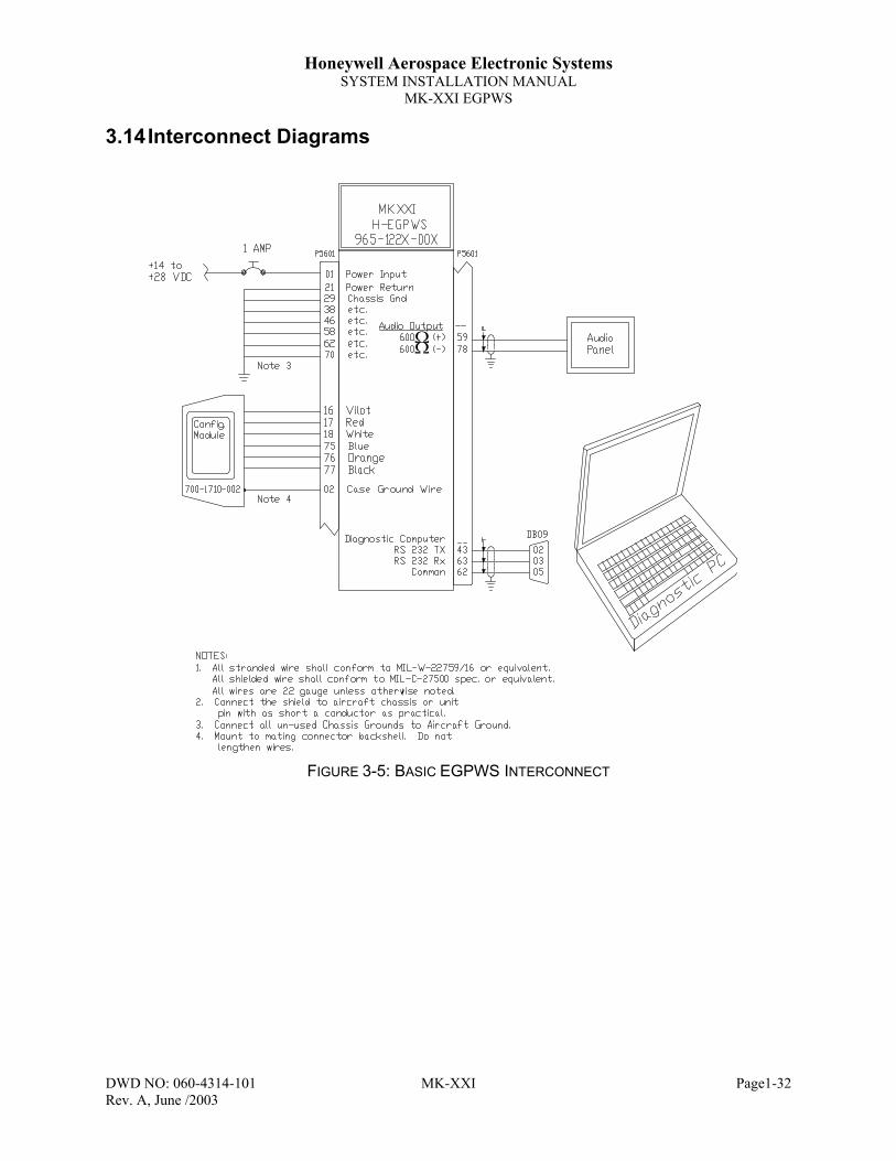
Honeywell Aerospace Electronic SystemsSYSTEM INSTALLATION MANUAL
MK-XXI EGPWS
DWD NO: 060-4314-101 MK-XXI Page1-32Rev. A, June /2003
3.14 Interconnect Diagrams
FIGURE 3-5: BASIC EGPWS INTERCONNECT
ΩΩ

Honeywell Aerospace Electronic SystemsSYSTEM INSTALLATION MANUAL
MK-XXI EGPWS
DWD NO: 060-4314-101 MK-XXI Page1-33Rev. A, June /2003
Ω
FIGURE 3-6: ALTITUDE SENSOR INTERCONNECT

Honeywell Aerospace Electronic SystemsSYSTEM INSTALLATION MANUAL
MK-XXI EGPWS
DWD NO: 060-4314-101 MK-XXI Page1-34Rev. A, June /2003
FIGURE 3-7: GPS POSITION SENSOR INTERCONNECT
BENDIX / KINGMK-XXI
H-EGPWS965-1227-00XP5601
GPS LS 429 Rx A
GPS LS 429 Rx B
08
27
GPS RECEIVER
LS ARINC 429 (A)
LS ARINC 429 (B)
a
b
10J
10K
4C
4D
K
L
N5
N6UN
S-1C
UNS-
1DUN
S-1K
UNS-
1MG
NS-X
LS
MP P2 P101
GPS RS-232 Rx
GPS RS-232 Cm
06
29
RS-232 (Tx)
RS-232 (Cm)(Chassis Gnd)
PPP1 MP
GNS
430/
530
KLN
900
KLN
9456 13 6

Honeywell Aerospace Electronic SystemsSYSTEM INSTALLATION MANUAL
MK-XXI EGPWS
DWD NO: 060-4314-101 MK-XXI Page1-35Rev. A, June /2003
This drawing does not include the recommended LOW ALT annunciator. Please refer to Section 1.10.3 foradditional information.
FIGURE 3-8: EATON ANNUNCIATOR SWITCHES
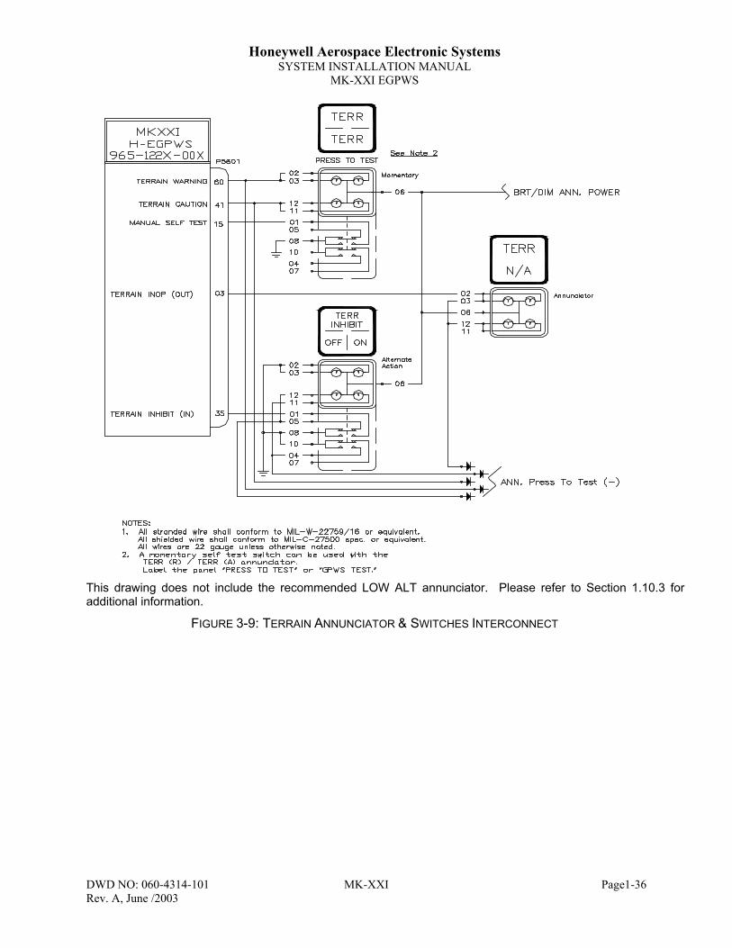
Honeywell Aerospace Electronic SystemsSYSTEM INSTALLATION MANUAL
MK-XXI EGPWS
DWD NO: 060-4314-101 MK-XXI Page1-36Rev. A, June /2003
This drawing does not include the recommended LOW ALT annunciator. Please refer to Section 1.10.3 foradditional information.
FIGURE 3-9: TERRAIN ANNUNCIATOR & SWITCHES INTERCONNECT
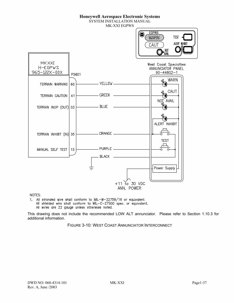
Honeywell Aerospace Electronic SystemsSYSTEM INSTALLATION MANUAL
MK-XXI EGPWS
DWD NO: 060-4314-101 MK-XXI Page1-37Rev. A, June /2003
This drawing does not include the recommended LOW ALT annunciator. Please refer to Section 1.10.3 foradditional information.
FIGURE 3-10: WEST COAST ANNUNCIATOR INTERCONNECT
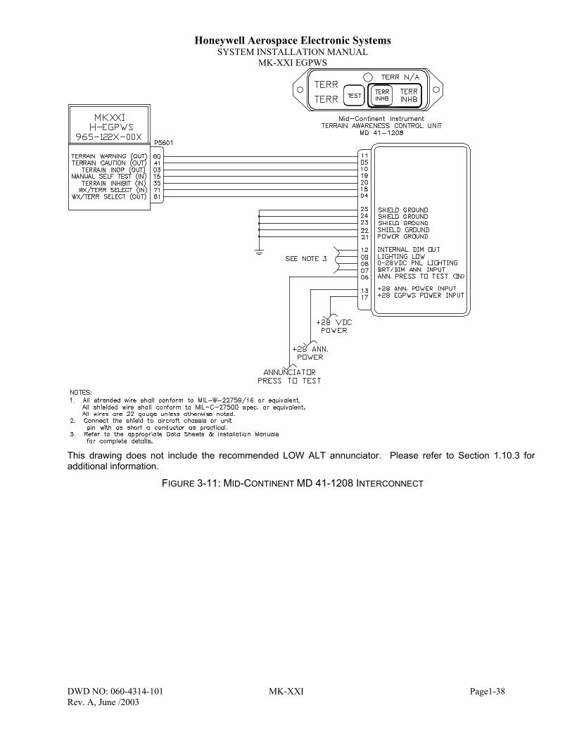
Honeywell Aerospace Electronic SystemsSYSTEM INSTALLATION MANUAL
MK-XXI EGPWS
DWD NO: 060-4314-101 MK-XXI Page1-38Rev. A, June /2003
This drawing does not include the recommended LOW ALT annunciator. Please refer to Section 1.10.3 foradditional information.
FIGURE 3-11: MID-CONTINENT MD 41-1208 INTERCONNECT

Honeywell Aerospace Electronic SystemsSYSTEM INSTALLATION MANUAL
MK-XXI EGPWS
DWD NO: 060-4314-101 MK-XXI Page1-39Rev. A, June /2003
This drawing does not include the recommended LOW ALT annunciator. Please refer to Section 1.10.3 foradditional information.
FIGURE 3-12: MID-CONTINENT MD 41-1308 INTERCONNECT

Honeywell Aerospace Electronic SystemsSYSTEM INSTALLATION MANUAL
MK-XXI EGPWS
DWD NO: 060-4314-101 MK-XXI Page1-40Rev. A, June /2003
Ω
FIGURE 3-13: IN 182/812 WX RADAR INDICATOR INTERCONNECT
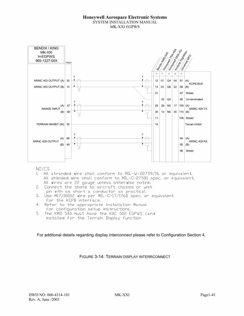
Honeywell Aerospace Electronic SystemsSYSTEM INSTALLATION MANUAL
MK-XXI EGPWS
DWD NO: 060-4314-101 MK-XXI Page1-41Rev. A, June /2003
FIGURE 3-14: TERRAIN DISPLAY INTERRCONNECT
BENDIX / KINGMK-XXI
H-EGPWS965-1227-00X
P5601
TERRAIN INHIBIT (IN) 35
ARINC 453 OUTPUT (A)
ARINC 453 OUTPUT (B)
30
10
P
P P
P
12
13
J1
Bend
ix KM
D-54
0
29
30
(A)
(B)
(A)
(B)ARINC 429 TX
KCPB BUS
(A)
(B)
47
66
Hone
ywel
l TRA
-45A
01
03
J1
28
13
Hone
ywel
l GNS
-XLS
Q4
Q6
J1
N5
N6
31
11
Shield
Shield
02 Un-terminated
Avidy
ne F
light
Max
04
22
J5
17
35
Unive
rsal
MFD
81
68
J1
105
115
14 Terrain Inhibit
Q5 80
67
106
P P
94
95
96
(A)
(B)ARINC 429 RX
Shield
(A)
(B)
68
49ARINC 429 OUTPUT
RANGE INPUT
For additonal details regarding display interconnect please refer to Configuration Section 4.
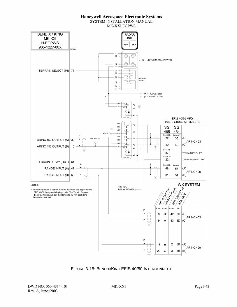
Honeywell Aerospace Electronic SystemsSYSTEM INSTALLATION MANUAL
MK-XXI EGPWS
DWD NO: 060-4314-101 MK-XXI Page1-42Rev. A, June /2003
FIGURE 3-15: BENDIX/KING EFIS 40/50 INTERCONNECT
BENDIX / KINGMK-XXI
H-EGPWS965-1227-00X
P5601
TERRAIN SELECT (IN) 71
WX SYSTEM
ARINC 453 OUTPUT (A)
ARINC 453 OUTPUT (B)
30
10
RADARIND
RDR TERR
AlternateAction
NC
NO
RELAY
D3
D1
C3
C1
B3
B1
A3
A1
D2
C2
B2
A2
X1
X2
0704
10
08
0501
1112
06
0302
AnnunciatorPress To Test
P
P P
P
22
49
BRT/DIM ANN. POWER
68
81
(H)
(C)
(A)
(B)
TERRAIN POP-UP 1
ARINC 453
ARINC 429
TERRAIN RELAY (OUT) 61
RANGE INPUT (A)
RANGE INPUT (B)
47
66
P
P
+28 VDCRELAY POWER
SEE NOTE 5
42
43
P5001
ART
2000
/210
0RT
A-4A
/B
2
3
(H)
(C)
(A)
(B)
ARINC 453
ARINC 429
BP
2D
3D
3B
4B
8
9
P1001
RS-1
81A/
811A
RS-8
41A/
861A
19
20
P1001
X
A
A
G
TERRAIN SELECTED 1
37
22
EFIS 40/50 MFDB/K SG 464/465 SYM GEN
+28 VDC
NO
RELAY
A3
A1A2
X1
X2
1. Terrain Selected & Terrain Pop-up discretes are applicable to EFIS 40/50 Integrated displays only. The Terrain Pop-up discrete, if used, will set the Range to 10 NM each time Terrain is selected.
NOTES:
SG464
SG465
P465-2B
P465-2B
P465-1B
P465-1A
35
49
67
54
P464-1C
P464-1C

Honeywell Aerospace Electronic SystemsSYSTEM INSTALLATION MANUAL
MK-XXI EGPWS
DWD NO: 060-4314-101 MK-XXI Page1-1Rev. A, June /2003
4 SECTION IV – SYSTEM INSTALLATION DESIGN
4.1 IntroductionFor proper operation the MK-XXI EGPWS must be programmed to select optional configuration items. Thissection will present the detail necessary to make the required configurable selections. The MK-XXI hasnumerous configurable Categories. A selection ID from each of these Categories must be identified and thenprogrammed into the configuration module per the procedure in Section 5. It is recommended that theCategory ID Selection Table (Section 4.3) be filled out and available for reference during the ConfigurationModule programming (Section 5.4.6).
4.2 Configuration Types (Categories)The selection of the basic interfaces to the EGPWS can be found in the following categories:
Aircraft / Mode Type Category 1
Air Data Input Type Category 2
Position Input Type Category 3
Terrain Display Type Category 4
I / O Discretes Type Category 5
Audio Menu Type Category 6
Audio Output Level Type Category 7
Altitude Monitor / MSL Select Type Category 8
Options Select Type Category 9
Attitude & Heading Select Type Category 10
Display Options Type Category 11

Honeywell Aerospace Electronic SystemsSYSTEM INSTALLATION MANUAL
MK-XXI EGPWS
DWD NO: 060-4314-101 MK-XXI Page1-2Rev. A, June /2003
4.3 Design/Planning System Configuration Identification (ID)Selection
These following sections define how the Category ID’s are selected for the interface to aircraft sensors andhow to select EGPWS performance options. This section and its sub-sections define the specific aircraftapplications of the EGPWS. The method to select the Configuration Identification (ID) for each Category Typeon a given aircraft installation is with the information in this document and the following table. This tableprovides the procedure to determine the Configuration ID selection required for any given aircraft installation.
Category SignalSelection Instructions Ident No.
1
Selects:
a) Aircraft Type
b) Mode Type
Using Table 4-2 and any sub-tablescontained within, locate the Aircraft / ModeType.
Record the Ident (ID No.) on the space availableon Ident column of this table. _______
ID #
2Selects:
a) Air Data Source
Using Table 4-3 and any sub-tablescontained within locates the desired Air Datasignal type.
Record the Ident (ID No.) on the space availableon Ident column of this table.
_______
ID #
3Selects:
a) Position Source
Using Table 4-20 and any sub-tablescontained within locates the desired Positionsignal type.
Record the Ident (ID No.) on the space availableon Ident column of this table.
_______
ID #
4Selects:
a) Display Config.
Using Table 4-26 and any sub-tablescontained within, locate the desired Displayindicator type / range bus type.
Record the Ident (ID No.) on the space availableon Ident column of this table.
_______
ID #
5
Selects:
a) Input DiscreteFunctions
b) Output DiscreteFunctions
Using Table 4-27 and any sub-tablescontained within, locate the desired I / ODiscrete type.
Record the Ident (ID No.) on the space availableon Ident column of this table.
_______
ID #
6Selects:
a) Audio Menu
Using Table 4-28 and any sub-tablescontained within, locate the desired AudioMenu type.
Record the Ident (ID No.) on the space availableon Ident column of this table.
_______
ID #
7Selects:
a) Audio OutputLevel
Using Table 4-29 and any sub-tablescontained within locates the desired Volumetype.
Record the Ident (ID No.) on the space availableon Ident column of this table. _______
ID #
8
Selects:
a) Geo. Alt.Display LabelText
b) Altitude MonitorDisplay Disable
c) Altitude MonitorCallout Disable
d) Altitude MonitorDisplay Disable
Using Table 4-30 and any sub-tablescontained within, select the desired True orFalse condition for Altitude Monitor DisplayDisable, Altitude Monitor Callout Disable, andAltitude Monitor Disable.
Record the Ident (ID No.) on the space availableon Ident column of this table.
_______
ID #
9Selects:
a) TA&D AlternatePop Up
Using Table 4-31 and any sub-tablescontained within, select the desired True orFalse condition for TA&D Alternate Pop Up.
Record the Ident (ID No.) on the space availableon Ident column of this table. _______
ID #
10Selects:
Attitude and Headingsource
Using Table 4-32 and any sub-tablescontained within, select the desired Roll andHeading sources
Record the Ident (ID No.) on the space availableon Ident column of this table. _______
ID #
11Selects:
Display Options
Using Table 4-41 and any sub-tablescontained within, select the desired displayoperation.
Record the Ident (ID No.) on the space availableon Ident column of this table.
_______
ID #
TABLE 4-1: CATEGORY ID SELECTION TABLE

Honeywell Aerospace Electronic SystemsSYSTEM INSTALLATION MANUAL
MK-XXI EGPWS
DWD NO: 060-4314-101 MK-XXI Page1-3Rev. A, June /2003
4.3.1 Configuration Selection Tables
The category columns define a category (or group) of functions or input devices that are selected through IDnumbers. The Category number identifies the subsection where the details are defined. For example AirData, Category 2, is defined in Section 4.3.1.2 and Position Input Source, Category 3, is defined in Section4.3.1.3.
4.3.1.1 Category 1, Aircraft / Mode Type Select
The following table provides identification of the basic mode types and associated parameters. In thiscategory only the following parameters are to be defined:
• Helicopter aircraft type with normal start-up default and Helicopter aircraft type with Low Altitude modestart-up default.
Please note that for release –005 Category 1 IDs have been renamed to reflect the selection of the speed inwhich the MK-XXI will provide aural and visual alerts (i.e. 60 or 70 kts. groundspeed) and the default startupmode (either Normal or Low Altitude).
ID Aircraft /Mode Type Description SW
Effectivity
128 128 Helo (60 Kts) -003129 129 Helo (60 Kts) (Low Altitude Mode Default) -003130 130 Helo (70 Kts) -005131 131 Helo (70 Kts) (Low Altitude Mode Default) -005
TABLE 4-2: AIRCRAFT / MODE TYPE SELECT

Honeywell Aerospace Electronic SystemsSYSTEM INSTALLATION MANUAL
MK-XXI EGPWS
DWD NO: 060-4314-101 MK-XXI Page1-4Rev. A, June /2003
4.3.1.2 Category 2, Air Data Input Select
The following table provides identification of the Air Data source type. In this category only the followingparameters are to be defined:
• Gillham/Gray coded altitude, uncorrected altitude or Baro altitude in an ARINC 429 or RS-232/422 format.OAT Temperature probe, Static Air Temperature (SAT) or additional items available from certain air datasystems.
Note: Data update rates listed in the tables below are the slowest acceptable rate.
ID Air Data TypeStatic Air
TemperatureType
Description
See TablesBelow
See TablesBelow
SWEffectivity
0 1 None Altitude Encoder (9 wire Gillham/Gray coded altitude) -003
1 1 T1 Altitude Encoder (9 wire Gillham/Gray coded altitude) with 500ΩOAT Temperature Probe -003
2 2 T2 Digital – ARINC 429 (Baro Alt & SAT) -003
3 3 T2 Digital – ARINC 429 (Baro Alt, Baro Rate, Corrected Altitude, &SAT) -003
4 2 None Digital – ARINC 429 (Baro Alt) -0035 3 None Digital – ARINC 429 (Baro Alt, Baro Rate, & Corrected Altitude) -0036 4 None Digital – ARINC 429 (Baro Alt & Baro Rate) -0037 4 T2 Digital – ARINC 429 (Baro Alt, Baro Rate, & SAT) -0038 5 None RS-232/422 Air Data Computer (Shadin 200) -0039 5 T3 RS-232/422 Air Data Computer (Shadin 200) with SAT -003
10 6 None RS-232 Encoded Altitude (Shadin Digitizers For UPS/Appollo at1200 bps) -003
11 6 T1 RS-232 Encoded Altitude ((Shadin Digitizers For UPS/Appollo at1200 bps) with 500Ω OAT Temperature Probe -003
12 7 None RS-232 Encoded Altitude (Shadin 17 Byte at 9600 bps) -003
13 7 T1 RS-232 Encoded Altitude (Shadin 17 Byte at 9600 bps) with 500ΩOAT Temperature Probe -003
14 8 None RS-232 Encoded Altitude (ICARUS Altitude (10 Byte) at 9600 bps) -003
15 8 T1 RS-232 Encoded Altitude (ICARUS Altitude (10 Byte) at 9600 bps)with 500Ω OAT Temperature Probe -003
16 9 None RS-232 Encoded Altitude (Northstar/Garmin at 2400 bps) -003
17 9 T1 RS-232 Encoded Altitude (Northstar/Garmin at 2400 bps) with 500ΩOAT Temperature Probe -003
18 10 None RS-232 Encoded Altitude (Magellan at 1200 bps) -003
19 10 T1 RS-232 Encoded Altitude (Magellan at 1200 bps) with 500Ω OATTemperature Probe -003
20 11 None RS-232 Encoded Altitude (ARNAV at 9600 bps) -003
21 11 T1 RS-232 Encoded Altitude (ARNAV at 9600 bps) with 500Ω OATTemperature Probe -003
24 13 5 Digital – ARINC 575 (i.e., Collins ADC-80, 81, 82) (Baro Alt, Baro Rate & SAT) -005
25 13 none Digital – ARINC 575 (i.e., Collins ADC-80, 81, 82) (Baro Alt & Baro Rate) -005
TABLE 4-3: AIR DATA INPUT SELECT

Honeywell Aerospace Electronic SystemsSYSTEM INSTALLATION MANUAL
MK-XXI EGPWS
DWD NO: 060-4314-101 MK-XXI Page1-5Rev. A, June /2003
PIN FUNCTION CONNECTION PIN TYPE CHANNELDESIGNATIONREFERENCE
Polarity/Configuration
Gray Code C4 J1-72 Input GND_DISC_09 GND = Active<not> GND = Inactive
Gray Code C2 J1-13 Input GND_DISC_10 GND = Active<not> GND = Inactive
Gray Code C1 J1-32 Input GND_DISC_11 GND = Active<not> GND = Inactive
Gray Code B4 J1-73 Input GND_DISC_01 GND = Active<not> GND = Inactive
Gray Code B2 J1-34 Input GND_DISC_02 GND = Active<not> GND = Inactive
Gray Code B1 J1-14 Input GND_DISC_03 GND = Active<not> GND = Inactive
Gray Code A4 J1-33 Input GND_DISC_04 GND = Active<not> GND = Inactive
Gray Code A2 J1-52 Input GND_DISC_05 GND = Active<not> GND = Inactive
Gray Code A1 J1-12 Input GND_DISC_06 GND = Active<not> GND = Inactive
TABLE 4-4: AIR DATA TYPE 1
CHANNEL429RX_3
CONNECT TO:ADC #1 (Low Speed)Format: ARINC 429
Fault Designation: AIR DATA BUSBus Type: Basic
A = J1-9B = J1-28
DataUncorrected. Baro. Alt
Label203
Sig. Bits17
Range±131,072 FT
Signal TypeBasic
Resolution1.0
Rate (ms)1000
TABLE 4-5: AIR DATA TYPE 2
CHANNEL429RX_3
CONNECT TO:ADC #1 (Low Speed)Format: ARINC 429
Fault Designation: AIR DATA BUSBus Type: Basic
A = J1-9B = J1-28
DataUncorrected. Baro. AltCorrected Baro. AltBarometric Rate
Label203204212
Sig. Bits171711
Range±131,072 FT±131,072 FT±32678 FPM
Signal TypeBasicBasicBasic
Resolution1.01.016.0
Rate (ms)100010001000
TABLE 4-6: AIR DATA TYPE 3
CHANNEL429RX_3
CONNECT TO:ADC #1 (Low Speed)Format: ARINC 429
Fault Designation: AIR DATA BUSBus Type: Basic
A = J1-9B = J1-28
DataUncorrected. Baro. AltBarometric Rate
Label203212
Sig. Bits1711
Range±131,072 FT±32678 FPM
Signal TypeBasicBasic
Resolution1.016.0
Rate (ms)10001000
TABLE 4-7: AIR DATA TYPE 4

Honeywell Aerospace Electronic SystemsSYSTEM INSTALLATION MANUAL
MK-XXI EGPWS
DWD NO: 060-4314-101 MK-XXI Page1-6Rev. A, June /2003
CHANNELADC_RXAADC_RXB
CONNECT TO: ADCFormat: RS-232(9600 BPS 8bit None)
Fault Designation: AIR DATA BUSBus Type: Basic
RX = J1-45Com = J1-65
DataPressure AltitudePressure Alt ChecksumBarometric RateBaro Rate Checksum
ID/byte64-697094-9899
Sig. BitsN/AN/AN/AN/A
Range-1000 – 55KN/A± 100 FPSN/A
Signal TypeBasicBasicBasicBasic
Resolution1 footN/A1 FPSN/A
Rate (ms)1600160016001600
TABLE 4-8: AIR DATA TYPE 5
CHANNELADC_RXAADC_TXA
CONNECT TO: ADCFormat: RS-232(1200 BPS 8bit None)
Fault Designation: AIR DATA BUSBus Type: Basic
RX = J1-45Com = J1-46
DataUncorrected. Baro. Alt
ID/byte#AL<sp>
Sig. Bits5
Range-1000 – 30000
Signal TypeBasic
*Resolution1 foot
Rate (ms)1000
* Indicates scaling resolution. Actual altitude resolution may be as coarse as 100 feet.
TABLE 4-9: AIR DATA TYPE 5
CHANNELADC_RXAADC_TXA
CONNECT TO:ADCFormat: RS-232(9600 BPS 8bit None)
Fault Designation: AIR DATA BUSBus Type: Basic
RX = J1-45Com = J1-46
DataUncorrected. Baro. Alt
ID/byteRMS<sp>
Sig. Bits5
Range-1000 – 30000
Signal TypeBasic
*Resolution1 foot
Rate (ms)1000
* Indicates scaling resolution. Actual altitude resolution may be as coarse as 100 feet.
TABLE 4-10: AIR DATA TYPE 7
CHANNELADC_RXAADC_TXA
CONNECT TO: ADCFormat: RS-232(9600 BPS 8bit None)
Fault Designation: AIR DATA BUSBus Type: Basic
RX = J1-45Com = J1-46
DataUncorrected. Baro. Alt
ID/byteALT
Sig. Bits5
Range-1000 – 30000
Signal TypeBasic
*Resolution1 foot
Rate (ms)1000
* Indicates scaling resolution. Actual altitude resolution may be as coarse as 100 feet.
TABLE 4-11: AIR DATA TYPE 8
CHANNELADC_RXAADC_TXA
CONNECT TO: ADCFormat: RS-232(2400 BPS 8bit None)
Fault Designation: AIR DATA BUSBus Type: Basic
RX = J1-45Com = J1-46
DataUncorrected. Baro. Alt
ID/byteALT
Sig. Bits5
Range-1000 – 30000
Signal TypeBasic
*Resolution1 foot
Rate (ms)1000
* Indicates scaling resolution. Actual altitude resolution may be as coarse as 100 feet.
TABLE 4-12: AIR DATA TYPE 9
CHANNELADC_RXAADC_TXA
CONNECT TO: ADCFormat: RS-232(1200 BPS 7bit Odd)
Fault Designation: AIR DATA BUSBus Type: Basic
RX = J1-45Com = J1-46
DataUncorrected. Baro. Alt
ID/byte$MGL
Sig. Bits5
Range-1000 – 30000
Signal TypeBasic
*Resolution1 foot
Rate (ms)1000
* Indicates scaling resolution. Actual altitude resolution may be as coarse as 100 feet.
TABLE 4-13: AIR DATA TYPE 10

Honeywell Aerospace Electronic SystemsSYSTEM INSTALLATION MANUAL
MK-XXI EGPWS
DWD NO: 060-4314-101 MK-XXI Page1-7Rev. A, June /2003
CHANNELADC_RXAADC_TXA
CONNECT TO: ADCFormat: RS-232(9600 BPS 8bit None)
Fault Designation: AIR DATA BUSBus Type: Basic
RX = J1-45Com = J1-46
DataUncorrected. Baro. Alt
ID/byte$PASHS
Sig.Bits5
Range-1000 – 30000
Signal TypeBasic
*Resolution1 meter
Rate (ms)1000
* Indicates scaling resolution. Actual altitude resolution may be as coarse as 100 feet.
TABLE 4-14: AIR DATA TYPE 11
CHANNEL429RX_3
CONNECT TO:ADC #1 (Low Speed)Format: ARINC 575
Fault Designation: AIR DATA BUSBus Type: Basic
A = J1-9B = J1-28
DataUncorrected. Baro. AltBarometric Rate
Label203212
Sig. Bits1711
Range±131,072 FT±20480 FPM
Signal TypeBasicBasic
Resolution1.010.0
Rate (ms)10001000
TABLE 4-15: AIR DATA TYPE 13
SIGNAL CONNECTION SUMMARY DATAOutside Air TempTotal Air Temperature
Probe elementExcitation: OAT_REF
Temp Input (probeelement):
Ground:
2.5 V = J1-20
(+) = J1-39(-) = J1-19
GND = J1-38
Format: DCInput Type: BasicFault Designation: STATIC AIR TEMPERATURE FAULT
OAT
PR
OBE
ELEM
ENT
20J1
(2.5 V Ref)
3919
Temp In
2.0 K Ohms
38
Voat
Chassis Gnd
-+
Note: Nominal 500 Ω Temperature Probe only.Resistance @ 0°C: 500Ω ± 0.6Ω
Note: With this configuration internal temperature is available. Reference 6.1.2.
TABLE 4-16: STATIC AIR TEMPERATURE TYPE 1
CHANNEL429RX_3
CONNECT TO:ADC #1 (Low Speed)Format: ARINC 429
Fault Designation: AIR DATA BUSBus Type: Basic
A = J1-9B = J1-28
DataStatic Air Temperature
Label213
Sig. Bits11
Range±512 Degrees
Signal TypeBasic
Resolution0.25
Rate (ms)1000
TABLE 4-17: STATIC AIR TEMPERATURE TYPE 2

Honeywell Aerospace Electronic SystemsSYSTEM INSTALLATION MANUAL
MK-XXI EGPWS
DWD NO: 060-4314-101 MK-XXI Page1-8Rev. A, June /2003
CHANNELADC_RXAADC_RXB
CONNECT TO: ADCFormat: RS-232(9600 BPS 8bit None)
Fault Designation: AIR DATA BUSBus Type: Basic
RX = J1-45Com = J1-65
DataStatic Air TemperatureSAT Checksum
ID/byte104-106107
Sig. BitsN/AN/A
Range± 60° CN/A
Signal TypeBasicBasic
Resolution1 degree CN/A
Rate (ms)16001600
TABLE 4-18: STATIC AIR TEMPERATURE TYPE 3
CHANNEL429RX_3
CONNECT TO:ADC #1 (Low Speed)Format: ARINC 575
Fault Designation: AIR DATA BUSBus Type: Basic
A = J1-9B = J1-28
DataStatic Air Temperature
Label213
Sig. Bits10
Range±512 Degrees
Signal TypeBasic
Resolution0.5
Rate (ms)1000
TABLE 4-19: STATIC AIR TEMPERATURE TYPE 5
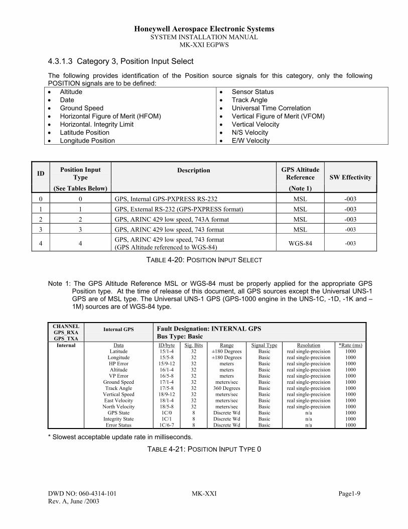
Honeywell Aerospace Electronic SystemsSYSTEM INSTALLATION MANUAL
MK-XXI EGPWS
DWD NO: 060-4314-101 MK-XXI Page1-9Rev. A, June /2003
4.3.1.3 Category 3, Position Input Select
The following provides identification of the Position source signals for this category, only the followingPOSITION signals are to be defined:• Altitude• Date• Ground Speed• Horizontal Figure of Merit (HFOM)• Horizontal. Integrity Limit• Latitude Position• Longitude Position
• Sensor Status• Track Angle• Universal Time Correlation• Vertical Figure of Merit (VFOM)• Vertical Velocity• N/S Velocity• E/W Velocity
ID Position InputType
Description GPS AltitudeReference
(See Tables Below) (Note 1)
SW Effectivity
0 0 GPS, Internal GPS-PXPRESS RS-232 MSL -0031 1 GPS, External RS-232 (GPS-PXPRESS format) MSL -0032 2 GPS, ARINC 429 low speed, 743A format MSL -0033 3 GPS, ARINC 429 low speed, 743 format MSL -003
4 4 GPS, ARINC 429 low speed, 743 format(GPS Altitude referenced to WGS-84) WGS-84 -003
TABLE 4-20: POSITION INPUT SELECT
Note 1: The GPS Altitude Reference MSL or WGS-84 must be properly applied for the appropriate GPSPosition type. At the time of release of this document, all GPS sources except the Universal UNS-1GPS are of MSL type. The Universal UNS-1 GPS (GPS-1000 engine in the UNS-1C, -1D, -1K and –1M) sources are of WGS-84 type.
CHANNELGPS_RXAGPS_TXA
Internal GPS Fault Designation: INTERNAL GPSBus Type: Basic
Internal DataLatitude
LongitudeHP ErrorAltitudeVP Error
Ground SpeedTrack Angle
Vertical SpeedEast Velocity
North VelocityGPS State
Integrity StateError Status
ID/byte15/1-415/5-8
15/9-1216/1-416/5-817/1-417/5-8
18/9-1218/1-418/5-81C/01C/1
1C/6-7
Sig. Bits32323232323232323232888
Range±180 Degrees±180 Degrees
metersmetersmeters
meters/sec360 Degreesmeters/secmeters/secmeters/sec
Discrete WdDiscrete WdDiscrete Wd
Signal TypeBasicBasicBasicBasicBasicBasicBasicBasicBasicBasicBasicBasicBasic
Resolutionreal single-precisionreal single-precisionreal single-precisionreal single-precisionreal single-precisionreal single-precisionreal single-precisionreal single-precisionreal single-precisionreal single-precision
n/an/an/a
*Rate (ms)1000100010001000100010001000100010001000100010001000
* Slowest acceptable update rate in milliseconds.
TABLE 4-21: POSITION INPUT TYPE 0

Honeywell Aerospace Electronic SystemsSYSTEM INSTALLATION MANUAL
MK-XXI EGPWS
DWD NO: 060-4314-101 MK-XXI Page1-10Rev. A, June /2003
CHANNELGPS_RXAGPS_TXA
External GPS(9600 baud)
Fault Designation: GPS BUSBus Type: Basic
ExternalJ1-29 (cm)J1-6 (Rx)
DataLatitude
LongitudeHP ErrorAltitudeVP Error
Ground SpeedTrack Angle
Vertical SpeedEast Velocity
North VelocityGPS State
Integrity StateError Status
ID/byte15/1-415/5-8
15/9-1216/1-416/5-817/1-417/5-8
18/9-1218/1-418/5-81C/01C/1
1C/6-7
Sig. Bits32323232323232323232888
Range±180 Degrees±180 Degrees
metersmetersmeters
meters/sec360 Degreesmeters/secmeters/secmeters/sec
Discrete WdDiscrete WdDiscrete Wd
Signal TypeBasicBasicBasicBasicBasicBasicBasicBasicBasicBasicBasicBasicBasic
Resolutionreal single-precisionreal single-precisionreal single-precisionreal single-precisionreal single-precisionreal single-precisionreal single-precisionreal single-precisionreal single-precisionreal single-precision
n/an/an/a
*Rate (ms)1000100010001000100010001000100010001000100010001000
* Slowest acceptable update rate in milliseconds.
TABLE 4-22: POSITION INPUT TYPE 1
CHANNEL429RX_2
CONNECT TO:GPS (Low Speed)
per ARINC 743A-2
Fault Designation: GPS BUSBus Type: Basic
A = J1-8 B = J1-27
DataLatitude - Normal
Longitude - NormalGPS Hor. Int. Limit
AltitudeVFOMHFOM
Ground SpeedTrack Angle
Vertical VelocityNorth/South VelocityEast/West Velocity
Sensor Status**UTC**Date
**This label is not required.Data used if present
Label110111130076136247112103165166174273125260
Sig. Bits2020172018181515151515191919
Range±180 Degrees±180 Degrees
16 nm±131,072 FT
32768 ft16 nm
±4096 Knots±180 Degrees±32768 Ft/Min±4096 Knots±4096 KnotsDiscrete WdDiscrete WdDiscrete Wd
Signal TypeBasicBasicBasicBasicBasicBasicBasicBasicBasicBasicBasicBasicBasicBasic
Resolution0.000171661376950.00017166137695
0.000122070.1250.125
0.0000610350.125
0.00549316406251
0.1250.125
n/a0.1 min1 day
*Rate (ms)10001000100010001000100010001000100010001000100010001000
*Slowest acceptable update rate in milliseconds.
TABLE 4-23: POSITION INPUT TYPE 2

Honeywell Aerospace Electronic SystemsSYSTEM INSTALLATION MANUAL
MK-XXI EGPWS
DWD NO: 060-4314-101 MK-XXI Page1-11Rev. A, June /2003
CHANNEL429RX_2
CONNECT TO:GPS (Low Speed)Per ARINC 743
Fault Designation: GPS BUSBus Type: Basic
A = J1-8B = J1-27
DataLatitude – Normal
Longitude – NormalGPS Hor. Int. Limit
AltitudeVFOMHFOM
Ground SpeedTrack Angle
Vertical VelocityNorth/South VelocityEast/West Velocity
Sensor Status**UTC**Date
**This label is not required.Data used if present
Label110111130076136247112103165166174273125260
Sig. Bits2020172015151515151515191919
Range±180 Degrees±180 Degrees
16 nm±131,072 FT1024 meters1024 meters±4096 Knots±180 Degrees±32768 Ft/Min±4096 Knots±4096 KnotsDiscrete WdDiscrete WdDiscrete Wd
Signal TypeBasicBasicBasicBasicBasicBasicBasicBasicBasicBasicBasicBasicBasicBasic
Resolution0.000171661376950.00017166137695
0.000122070.125
0.031250.031250.125
0.00549316406251
0.1250.125
n/a0.1 min1 day
*Rate (ms)10001000100010001000100010001000100010001000100010001000
*Slowest acceptable update rate in milliseconds.
TABLE 4-24: POSITION INPUT TYPE 3
CHANNEL429RX_2
CONNECT TO:GPS (Low Speed)per ARINC 743
Fault Designation: GPS BUSBus Type: Basic
A = J1-8B = J1-27
DataLatitude – Normal
Longitude – NormalGPS Hor. Int. Limit
AltitudeVFOMHFOM
Ground SpeedTrack Angle
Vertical VelocityNorth/South VelocityEast/West Velocity
Sensor Status**UTC**Date
**This label is not required.Data used if present
Label110111130076136247112103165166174273125260
Sig. Bits2020172015151515151515191919
Range±180 Degrees±180 Degrees
16 nm±131,072 FT1024 meters1024 meters±4096 Knots±180 Degrees±32768 Ft/Min±4096 Knots±4096 KnotsDiscrete WdDiscrete WdDiscrete Wd
Signal TypeBasicBasicBasicBasicBasicBasicBasicBasicBasicBasicBasicBasicBasicBasic
Resolution0.000171661376950.00017166137695
0.000122070.125
0.031250.031250.125
0.00549316406251
0.1250.125
n/a0.1 min1 day
*Rate (ms)10001000100010001000100010001000100010001000100010001000
*Slowest acceptable update rate in milliseconds.
TABLE 4-25: POSITION INPUT TYPE 4

Honeywell Aerospace Electronic SystemsSYSTEM INSTALLATION MANUAL
MK-XXI EGPWS
DWD NO: 060-4314-101 MK-XXI Page1-12Rev. A, June /2003
4.3.1.4 Category 4, Terrain Display Select
The following table has an identification number (ID) associated with each Terrain Display configuration. Eachof the ID rows has a group number for the Display Configuration, the Input Control. The TA&D Pop-UpDisable function is defined by a Boolean.
In this category the ID number configures the following signals:Signal Name Signal Type Defined ByTerrain Display Bus: KCPB or ARINC 453 Display Configuration GroupRange Bus: ARINC 429 Display Input Control GroupTA&D Alternate Pop Up Boolean Defined directly in Table
ID DisplayConfig.Group
Display InputControl Group
Output 429Bus Group Application Notes SW Effectivity
0 0 0 0 KCPB -003
1 NONE NONE 0 No Display -003
2 1 1 0 Bendix IN-182A, IN-812A -003
3 2 1 0 Bendix IN-842A, IN-862A -003
4 3 2 0 Bendix RDR 4A/B PPI(with blue waters modification) -003
Display ID’s 5 & 6 Require a source of Magnetic Heading (See Table 4-32 for connection information)
5 4 1 0 EFIS 40/50 Non-Integrated -0036 5 1 0 EFIS 40/50 Integrated -003
TABLE 4-26: TERRAIN DISPLAY SELECT

Honeywell Aerospace Electronic SystemsSYSTEM INSTALLATION MANUAL
MK-XXI EGPWS
DWD NO: 060-4314-101 MK-XXI Page1-13Rev. A, June /2003
4.3.1.5 Category 5, Input / Output Discrete Type Select
The following table provides identification of the Input/Output Discrete Type.
ID Input/OutputDiscrete Type Description SW Effectivity
128 128 Helicopter input / output discretes (Lamp Format 2) -003129 129 Helicopter input / output discretes (Lamp Format 2) with 429 discretes -003130 130 Helicopter input / output discretes (Lamp Format 2) with 429 discretes
except Terrain Inhibit-003
Note 1: If a single cockpit lamp is desired for Terrain Cautions and Warnings, J1-60 and J1-41 can be diodeOR'd together to drive one lamp.
TABLE 4-27: INPUT/OUTPUT DISCRETE TYPE SELECT
4.3.1.6 Category 6, Audio Menu Select
The following table provides identification of the Voice Menu type
ID Audio MenuType Description SW
Effectivity
128 128 Helicopter with Be Alert Terrain INOP -003129 129 Helicopter without Be Alert Terrain INOP -003
Note: If Category 1 selected ID #0 (TSO C151b Class B curve set) Category 6 ID #1 (Alternate) must beselected to be in compliance with the TSO requirements.
TABLE 4-28: AUDIO MENU TYPE
4.3.1.7 Category 7, Audio Output Level
The following table provides identification of the Audio Output Level type. Each entry in the ID columncorresponds to a particular nominal alert output level selection (Max, -6 dB, -12 dB, -18dB and –24dB). Thenominal “Max” output is 100 mW rms for the 600-ohm output. The output power level will be the nominalmaximum output 100 mW reduced by the selected volume type.
ID Volume Type SWEffectivity
0 Maximum (600Ω ≈ 100mW) -0031 - 6 dB -0032 -12 dB -0033 -18 dB -0034 -24 dB -003
TABLE 4-29: AUDIO OUTPUT LEVEL

Honeywell Aerospace Electronic SystemsSYSTEM INSTALLATION MANUAL
MK-XXI EGPWS
DWD NO: 060-4314-101 MK-XXI Page1-14Rev. A, June /2003
4.3.1.8 Category 8, Altitude Monitor Options
The following table provides identification of the Altitude Monitor Options. Each entry in the ID columncorresponds to a particular combination of Altitude Monitor Display Disable, Altitude Monitor Callout Disable,and Altitude Monitor Disable. In addition it allows the selection of the Geometric Altitude display tag, eitherMSL (Mean Sea Level) or GSL (Geodetic Sea Level).
ID
GeoAltDisplay
Label Text
AltitudeMonitorDisable
AltitudeMonitorCalloutDisable
AltitudeMonitorDisplayDisable
(Note 1)
SW Effectivity
0 MSL False False False -0031 MSL False False True -0032 MSL False True False -0033 MSL False True True -0034 MSL True True True -0035 GSL False False False -0036 GSL False False True -0037 GSL False True False -0038 GSL False True True -0039 GSL True True True -003
TABLE 4-30: ALTITUDE MONITOR OPTIONS
Note 1: The GeoAlt Display Label Text configuration item only controls the display of the MSL text on thosedisplay in which the H-EGPWC is drawing the text on the display.
4.3.1.9 Category 9, Terrain Display Alternate Pop Up Option
The following table provides identification of the Terrain Display Alternate Pop Up Option. TA&D AlternatePop Up = False allows automatic Pop Up On Caution or Warnings. TA&D Alternate Pop Up = True disablesthe automatic Pop Up feature. To select terrain display pop up option the display and / or system installationmust be compatible.
ID TA&D AlternatePop Up Disable
SWEffectivity
0 False -0031 True -003
Note: Select False if Pop Up is desired.
TABLE 4-31: TERRAIN DISPLAY ALTERNATE POP UP DISABLE OPTION
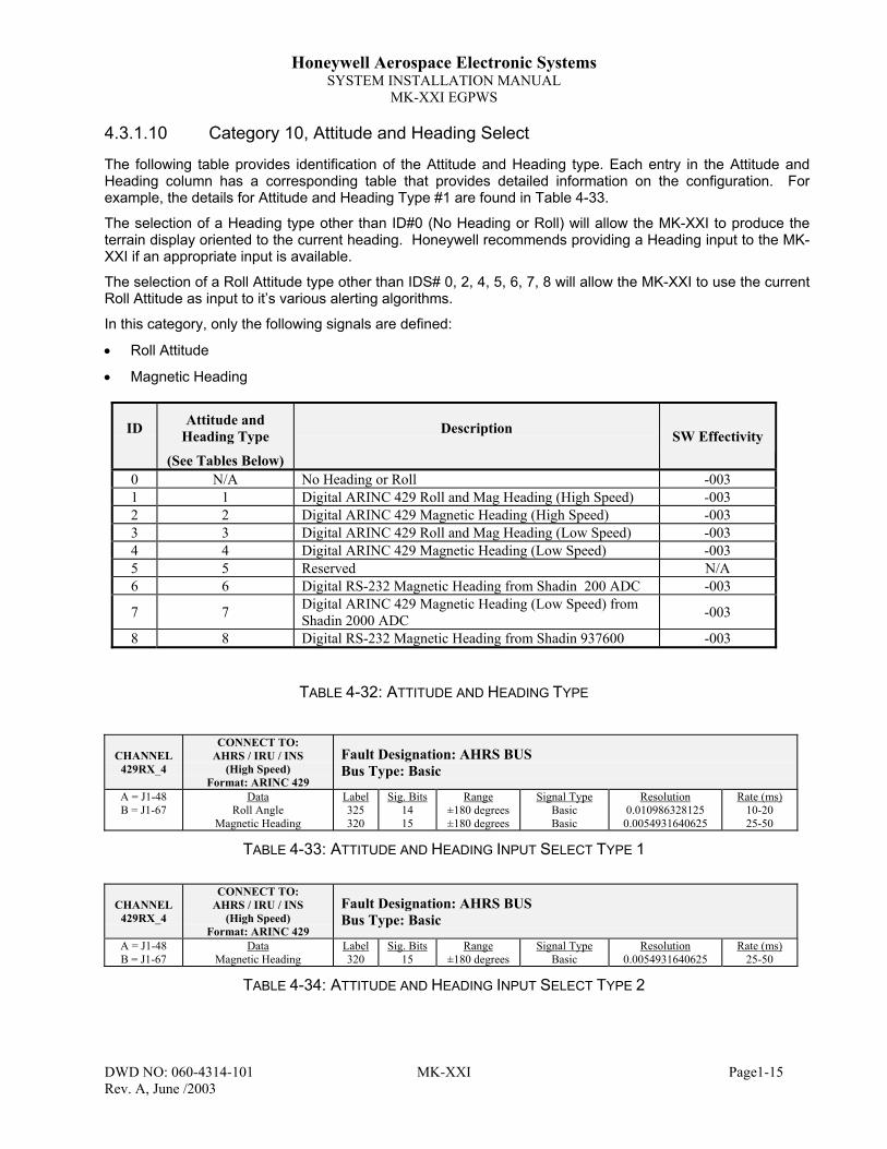
Honeywell Aerospace Electronic SystemsSYSTEM INSTALLATION MANUAL
MK-XXI EGPWS
DWD NO: 060-4314-101 MK-XXI Page1-15Rev. A, June /2003
4.3.1.10 Category 10, Attitude and Heading Select
The following table provides identification of the Attitude and Heading type. Each entry in the Attitude andHeading column has a corresponding table that provides detailed information on the configuration. Forexample, the details for Attitude and Heading Type #1 are found in Table 4-33.
The selection of a Heading type other than ID#0 (No Heading or Roll) will allow the MK-XXI to produce theterrain display oriented to the current heading. Honeywell recommends providing a Heading input to the MK-XXI if an appropriate input is available.
The selection of a Roll Attitude type other than IDS# 0, 2, 4, 5, 6, 7, 8 will allow the MK-XXI to use the currentRoll Attitude as input to it’s various alerting algorithms.
In this category, only the following signals are defined:
• Roll Attitude
• Magnetic Heading
ID Attitude andHeading Type Description
(See Tables Below)
SW Effectivity
0 N/A No Heading or Roll -0031 1 Digital ARINC 429 Roll and Mag Heading (High Speed) -0032 2 Digital ARINC 429 Magnetic Heading (High Speed) -0033 3 Digital ARINC 429 Roll and Mag Heading (Low Speed) -0034 4 Digital ARINC 429 Magnetic Heading (Low Speed) -0035 5 Reserved N/A6 6 Digital RS-232 Magnetic Heading from Shadin 200 ADC -003
7 7 Digital ARINC 429 Magnetic Heading (Low Speed) fromShadin 2000 ADC -003
8 8 Digital RS-232 Magnetic Heading from Shadin 937600 -003
TABLE 4-32: ATTITUDE AND HEADING TYPE
CHANNEL429RX_4
CONNECT TO:AHRS / IRU / INS
(High Speed)Format: ARINC 429
Fault Designation: AHRS BUSBus Type: Basic
A = J1-48B = J1-67
DataRoll Angle
Magnetic Heading
Label325320
Sig. Bits1415
Range±180 degrees±180 degrees
Signal TypeBasicBasic
Resolution0.0109863281250.0054931640625
Rate (ms)10-2025-50
TABLE 4-33: ATTITUDE AND HEADING INPUT SELECT TYPE 1
CHANNEL429RX_4
CONNECT TO:AHRS / IRU / INS
(High Speed)Format: ARINC 429
Fault Designation: AHRS BUSBus Type: Basic
A = J1-48B = J1-67
DataMagnetic Heading
Label320
Sig. Bits15
Range±180 degrees
Signal TypeBasic
Resolution0.0054931640625
Rate (ms)25-50
TABLE 4-34: ATTITUDE AND HEADING INPUT SELECT TYPE 2

Honeywell Aerospace Electronic SystemsSYSTEM INSTALLATION MANUAL
MK-XXI EGPWS
DWD NO: 060-4314-101 MK-XXI Page1-16Rev. A, June /2003
CHANNEL429RX_4
CONNECT TO:AHRS / IRU / INS
(Low Speed)Format: ARINC 429
Fault Designation: AHRS BUSBus Type: Basic
A = J1-48B = J1-67
DataRoll Angle
Magnetic Heading
Label325320
Sig. Bits1415
Range±180 degrees±180 degrees
Signal TypeBasicBasic
Resolution0.0109863281250.0054931640625
Rate (ms)10-2025-50
TABLE 4-35: ATTITUDE AND HEADING INPUT SELECT TYPE 3
CHANNEL429RX_4
CONNECT TO:AHRS / IRU / INS
(Low Speed)Format: ARINC 429
Fault Designation: AHRS BUSBus Type: Basic
A = J1-48B = J1-67
DataMagnetic Heading
Label320
Sig. Bits15
Range±180 degrees
Signal TypeBasic
Resolution0.0054931640625
Rate (ms)25-50
TABLE 4-36: ATTITUDE AND HEADING INPUT SELECT TYPE 4
TYPE 5 RESERVEDTABLE 4-37: ATTITUDE AND HEADING INPUT SELECT TYPE 5
CHANNELADC_RXA
CONNECT TO:ADC (Shadin 200)Format: RS-232(9600 BPS)
Fault Designation: AIR DATA BUSBus Type: Basic
RX = J1-45Com = J1-46
DataMagnetic HeadingMagnetic Heading Checksum
ID/byte101-102103
Sig. BitsN/AN/A
Range Signal TypeBasicBasic
Resolution1 degree CN/A
Rate (ms)16001600
Note: This configuration MUST be used in combination with Air Data ID 8 or 9.
TABLE 4-38: ATTITUDE AND HEADING INPUT SELECT TYPE 6
CHANNEL429RX_3
CONNECT TO:ADC (Shadin 2000)
(Low Speed)Format: ARINC 429
Fault Designation: AIR DATA BUSBus Type: Basic
A = J1-9B = J1-28
DataMagnetic Heading
Label320
Sig. Bits15
Range±180 degrees
Signal TypeBasic
Resolution0.0054931640625
Rate (ms)100
Note: This configuration MUST be used in combination with Air Data ID 2…7.
TABLE 4-39: ATTITUDE AND HEADING INPUT SELECT TYPE 7
CHANNELAHRS_RX
CONNECT TO:SHADIN 937600Format: RS-232
(1200 baud)
Fault Designation: AHRS BUSBus Type: Basic
RX = J1-24Com = J1-70
DataMagnetic Heading
FormatSee Shadin
937600 manual
Sig. Bitsn/a
Range360 Degrees
Resolution0.1 deg
*Rate (ms)1000
• Slowest acceptable update rate in milliseconds.
Note: The input from this converter (synchro to RS-232) to the MK-XXI does NOT provide validity. Ifthe compass system fails and does not supply active synchro input to this converter, theconverter continues to supply non-valid data. It is HIGHLY recommended that the validityoutput of the compass system be tied to a relay supplying power to this converter.
TABLE 4-40: ATTITUDE AND HEADING INPUT SELECT TYPE 8

Honeywell Aerospace Electronic SystemsSYSTEM INSTALLATION MANUAL
MK-XXI EGPWS
DWD NO: 060-4314-101 MK-XXI Page1-17Rev. A, June /2003
4.3.1.11 Category 11, Display Option Select
The following table provides identification of the Display Option type. Each entry in the ID columncorresponds to a particular combination of Display Option configuration (i.e. how the terrain displayoperates).. New to this category you can now select the Normal Helicopter TA&D Display Pop Up RangeSelection and Low Altitude Helicopter TA&D Display Pop Up Range Selection.
This Category primarily allows the selection of how the terrain display operates at slower speeds. Thevarious speeds, selectable below, allow terrain display operation to meet varying operator demands. It nowalso allows the selection of the ranges for normal & low altitude pop-up ranges required to interface withdisplays not capable of displaying lower range values (Honeywell recommends 5nm for normal mode &2.5nm for low altitude, if the interfaced display is capable).
This Category selects the output type (orientation) and function of the MK-XXI’s terrain display. Morespecifically this selection will determine the operation of the terrain display output when on the ground, at slowground speeds and when transitioning to or from a hover.
Upon startup and when the MK-XXI system finishes initializing (given a non-INOP condition) it will provide aterrain display image. This image, depending upon this Category selection, will be oriented to North-Up,oriented to Track-up or oriented Heading up.
If you have selected an Attitude & Heading type (Category 10) with a heading input (IDs 1-4 and 6-8) andgiven the heading input to the MK-XXI is valid, the terrain display will be oriented to the aircraft’s currentheading. Note: If you have selected a Category 10 (Attitude & Heading type) with a heading input it isrequired to select either ID 2 or 3 for this category.If a selection of the Attitude & Heading type (Category 10) does not provide the MK-XXI with Heading (i.e. ID1) the terrain display will either be North UP or Blank w/ message until (depending upon selection below) avalid ground speed is supplied and the aircraft reaches the selected speed. This is for aircraft for without ausable heading input to the MK-XXI.
When the input of ground speed (with hysterisis) is below the selected value (note the values of the variousIDs below) the terrain display with either be Blank w/message or North Up (depending upon the selection ofCategory 10). For example; If you select ID 0 below, the terrain display will be North Up until the aircraft’sground speed reaches 45 kts. The display will then transition to Track Up and remains Track UP until theaircraft transitions below 15 kts.
The North Up Display Blanking selection (below) will provide a terrain display oriented to North regardless ofaircraft heading (remember below the ground speed selected below). The `Blank w/message’ terrain displaywill output a blank display with the message `DISPLAY UNAVAIL’.
In this category, only the following signals are defined:
• Track Display Hysterisis limits
• Display Blanking option
• Normal Helicopter TA&D Display Pop Up Range Selection
• Low Altitude Helicopter TA&D Display Pop Up Range Selection
If the display type selected via Category 4 supports Auto Pop-Up and Auto-Ranging then the Helo NormalPop-Up Range Select chooses the Terrain Display Range to be forced during a non-Low Altitude Mode Pop-Up. The 5NM range selection is recommended if the selected display type supports a 5 NM range.
If the display type selected via Category 4 supports Auto Pop-Up and Auto-Ranging then the Helo LowAltitude Pop-Up Range Select chooses the Terrain Display Range to be forced during a Low Altitude ModePop-Up. The 2.5NM range selection is recommended if the selected display type supports a 2.5 NM range.

Honeywell Aerospace Electronic SystemsSYSTEM INSTALLATION MANUAL
MK-XXI EGPWS
DWD NO: 060-4314-101 MK-XXI Page1-18Rev. A, June /2003
ID
HeloNormalPop-Up
Range Select(in NM)
HeloLow Altitude
Pop-Up RangeSelect
(in NM)4
DisplayOption Type
Track Hysterisis Display Blanking SWEffectivity
0 5 2.5 0 Classic Fixed Wing (45 kts valid/ 15 kts invalid) North Up -0031 5 2.5 1 “ Blank w/message -0032 5 2.5 2 No limit (-1 kts valid; i.e. always) North Up -0033 5 2.5 3 “ Blank w/message -0034 5 2.5 4 10 Kts (15 kts valid / 5 kts invalid) North Up -0035 5 2.5 5 “ Blank w/message -0036 5 2.5 6 15 Kts (20 kts valid / 10 kts invalid) North Up -0037 5 2.5 7 “ Blank w/message -0038 5 2.5 8 20 Kts (25 kts valid / 15 kts invalid) North Up -0039 5 2.5 9 “ Blank w/message -003
10 5 2.5 10 25 Kts (30 kts valid / 20 kts invalid) North Up -00311 5 2.5 11 “ Blank w/message -00312 5 2.5 12 30 Kts (35 kts valid / 25 kts invalid) North Up -00313 5 2.5 13 “ Blank w/message -003
16 5 5 0 Classic Fixed Wing (45 kts valid/ 15 kts invalid) North Up -00517 5 5 1 “ Blank w/message -00518 5 5 2 No limit (-1 kts valid; i.e. always) North Up -00519 5 5 3 “ Blank w/message -00520 5 5 4 10 Kts (15 kts valid / 5 kts invalid) North Up -00521 5 5 5 “ Blank w/message -00522 5 5 6 15 Kts (20 kts valid / 10 kts invalid) North Up -00523 5 5 7 “ Blank w/message -00524 5 5 8 20 Kts (25 kts valid / 15 kts invalid) North Up -00525 5 5 9 “ Blank w/message -00526 5 5 10 25 Kts (30 kts valid / 20 kts invalid) North Up -00527 5 5 11 “ Blank w/message -00528 5 5 12 30 Kts (35 kts valid / 25 kts invalid) North Up -00529 5 5 13 “ Blank w/message -005
32 10 10 0 Classic Fixed Wing (45 kts valid/ 15 kts invalid) North Up -00533 10 10 1 “ Blank w/message -00534 10 10 2 No limit (-1 kts valid; i.e. always) North Up -00535 10 10 3 “ Blank w/message -00536 10 10 4 10 Kts (15 kts valid / 5 kts invalid) North Up -00537 10 10 5 “ Blank w/message -00538 10 10 6 15 Kts (20 kts valid / 10 kts invalid) North Up -00539 10 10 7 “ Blank w/message -00540 10 10 8 20 Kts (25 kts valid / 15 kts invalid) North Up -00541 10 10 9 “ Blank w/message -00542 10 10 10 25 Kts (30 kts valid / 20 kts invalid) North Up -00543 10 10 11 “ Blank w/message -00544 10 10 12 30 Kts (35 kts valid / 25 kts invalid) North Up -00545 10 10 13 “ Blank w/message -005
TABLE 4-41: DISPLAY OPTION TYPE

Honeywell Aerospace Electronic SystemsSYSTEM INSTALLATION MANUAL
MK-XXI EGPWS
DWD NO: 060-4314-101 MK-XXI Page5-1Rev. A, June /2003
5 SECTION V - INSTALLATION CONFIGURATION &CHECKOUT
5.1 IntroductionThe procedures for programming the Configuration Module, ground testing the MK XXI EGPWS after it isinstalled in the aircraft and installing the Regional Terrain Database card are described in the followingsections.
Configuration is explained in the first part of this section. The configuration process and the tools needed aredescribed below.
The Post-Installation Checkout, Section 5.5, verifies the proper operation of the MK XXI EGPWS system.These procedures are used after the units have been installed and the configuration module has beenprogrammed. Thereafter, these procedures can be used as an operational check. These tests are performedon the ground.
While many of these tests can be performed indoors, the aircraft may need to be outdoors, away from signalobstructions, so that GPS is able to receive satellites before the system can be fully tested.
The process for installing or changing the Regional Terrain Database card is described in this section. Theappropriate Database card must be installed for the system to operate normally.
5.1.1 Installation SequenceThis section will describe the normal sequence for new installations of the MK-XXI EGPWS system.Honeywell recommends following this sequence until achieving a comfortable level of experience with theMK-XXI system.
Installation Sequence:
1. Perform system installation design per Section 4 to select configurable items and ready Table 4-1:Category ID Selection Table.
2. Ensure MK-XXI system and aircraft installation is ready for installation per the details in Section 2.
3. Perform Installation Wiring Verification per instructions in Section 5.2.
4. Perform Terrain Database Installation & Verification per Section 5.3.
5. Perform Configuration Module programming per Section 5.4.4.
6. Perform Post Installation Ground Test / Checkout per Section 5.5.
7. Perform System Self Test per Section 5.6

Honeywell Aerospace Electronic SystemsSYSTEM INSTALLATION MANUAL
MK-XXI EGPWS
DWD NO: 060-4314-101 MK-XXI Page5-2Rev. A, June /2003
5.2 Installation – Aircraft Wiring Verification1. With all units disconnected and aircraft power off, do a point to point wiring check using an Ohm meter to
verify proper wiring interconnect.
2. With all units disconnected, apply aircraft DC power and verify that power is supplied to the power inputpins.
3. Remove DC power and install MK-XXI.
5.3 Regional Terrain Database CardPlease read this section and the Notes carefully before proceeding with Terrain Database cardinstallation.The MK XXI system contains a terrain, obstacle and runway database required for system operation. Thisdatabase is supplied separately from the unit to ensure the most recent database is shipped with eachsystem.
The Regional Terrain Database Card is a CompactFlash data card that resides in a slot beneath a softplastic cover on the top of the MK XXI unit. See Figure 2-1: EGPWS Computer Outline Drawing for a locationdiagram.
The terrain database card is removed and installed when power is NOT applied to the system.
The EGPWS computer may be removed from the aircraft to extract and install database cards if the mountinglocation does not provide enough clearance.
See the Pilot's Guide for a complete description of the Regional Terrain Database.
Note: During the first startup after loading a new terrain database card the MK-XXI goes through aterrain validation routine. This routine will take approximately 30+ minutes.
5.3.1 Regional Terrain Database Card Installation
Upon first time installation of the MK XXI LRU into the aircraft the following procedures should be performed.Similarly, follow these procedures when changing or updating the Regional Terrain Database card.
Installing the Regional Terrain database card is accomplished by:1. Remove DC power2. Carefully unpack the MK XXI CompactFlash database card from the shipping container.3. Check that the number on the database card is appropriate to the region.4. Open the top of the MK XXI computer by moving the plastic cover to the side.5. Press the ejector button located within the unit to remove the existing database card, if installed.6. Ensure proper alignment of the new database card per the labeled alignment points.7. Insert the database card firmly into the unit.8. Replace the cover and ensure a complete seal of the database cover.9. Apply DC power and allow approximately 30+ minutes for database verification.
Note: When the database card is updated it is highly recommended that the database verificationprocedure be followed.

Honeywell Aerospace Electronic SystemsSYSTEM INSTALLATION MANUAL
MK-XXI EGPWS
DWD NO: 060-4314-101 MK-XXI Page5-3Rev. A, June /2003
5.3.2 Regional Terrain Database Card Verification
Note: If the unit has went through the initial database verification process, See Section 5.3.1 (whenpower is first applied after database load) then the verification process in this section neednot be performed.
1. After Configuration Module programming, use the WinViews diagnostic port interface to perform thefollowing commands: (Please see attachment "WinViews for the MK XXI EGPWS")
2. At the WinViews command prompt type:>FHE <enter>(Then type Y immediately after pressing <enter>)
This procedure will validate the contents of the terrain database and should take approximately 30+ minutesto complete. Upon successful completion of this test the system is ready to perform the ground testprocedure. This procedure is highly recommended anytime that the database is updated.
5.3.3 Regional Terrain Database Card Updates
Regional Terrain databases can be ordered for card updates or another region by contacting; HoneywellInternational Inc. See Section 1.11 for contact details.

Honeywell Aerospace Electronic SystemsSYSTEM INSTALLATION MANUAL
MK-XXI EGPWS
DWD NO: 060-4314-101 MK-XXI Page5-4Rev. A, June /2003
5.4 Configuration Setup & ProgrammingThe MK XXI EGPWS reads the aircraft's installation configuration from the configuration module, which isinstalled on the unit mating connector. The configuration module must have the aircraft-specific equipmentconfiguration ID (identification) string written to it before the EGPWS is operational. Once the configurationmodule is programmed, the MK XXI can be removed and replaced without re-programming. This section willdetail the configuration options, configuration instructions, and initial configuration of a new configurationmodule for the MK XXI EGPWS.
The aircraft-specific configuration items include selecting choices for the type of aircraft operation, the altitudesource, the position source, the type of terrain display, type of lamp discretes, audio menus and volumeoutput levels and some special operational features.
5.4.1 Equipment Needed1. MK XXI EGPWS Installed And Operating.
The Regional Terrain Database should be installed. See Section 5.3 for complete instructions.2. IBM or Compatible PC with an available RS-232 serial port3. Interconnect Cable between the EGPWS and PC (see Figure 3-5)4. WinViews - a diagnostic program that runs in Windows on a PC
5.4.2 WinViews
WinViews is an acronym for (Windows Virtual Interface to the Enhanced Warning System). WinViews is asoftware tool developed by Honeywell to communicate with the EGPWS. WinViews provides a detailed statusof the software configuration and input signals, which enables quick identification of system configuration, andis utilized for programming the system.
WinViews runs on a diagnostic PC with Windows 3.1 or higher and communicates with the EGPWC by aserial cable (com port) connection. WinViews automatically configures the communications port of the PC. AUser’s Guide to WinViews is included with the software package. The software package consists of theexecutable file, a help file and sample command files.
WinViews HELP, as well as many other menu items are active even though the program is fully operationalwhen communications is established with the EGPWS.
Please see "WinViews for the EGPWS" for additional information.
To obtain a copy of the WinViews software, go to http://www.egpws.com or contact:
Honeywell Aerospace Electronic SystemsBR&GA Product Support,MK XXI Product SpecialistPhone:800-257-0726Fax: 913-712-1306

Honeywell Aerospace Electronic SystemsSYSTEM INSTALLATION MANUAL
MK-XXI EGPWS
DWD NO: 060-4314-101 MK-XXI Page5-5Rev. A, June /2003
5.4.3 WinViews Operation1. Connect the PC to the EGPWC using an RS-232 cable.2. Start the PC, ensuring Windows 3.1, or higher is running3. Apply power to the MK-XXI.
(Note: If the Terrain Database has not been validated by the MK_XXI during this firstsystem startup the MK-XXI goes through a validation routine. This routine can takeapproximately 30+ minutes. After validation is complete the MK-XXI will continue withsystem startup and accept the Ctrl Z command and provide the > command prompt.)
4. Start the WinViews.exe program, ensure the correct port is selected and connected to the MKXXI; type Ctrl Z
5. Use F6 to switch between Terminal and Display mode. Various commands are available in bothmodes.
6. Type “HELP” or “?” (then press Enter) for a list of the commands available.
5.4.4 Configuration Module Programming Instructions
The Configuration Module Programming is completed via the RS-232 port connected to a PC runningWinViews. The application code is capable of loading the Configuration Module with new data.
This programming is achieved by using the WinViews software. In WinViews, the EGPWS will accept validcommands. To prevent inadvertent access to the Configuration Module’s EEPROM the keyboard monitor isset up with a tiered menu. The keyboard monitor command “CFG” is used to gain access to the ConfigurationMonitor.
The command to program the memory with the Configuration String is “CUW”. This command takes a pre-configured String (defined below) containing the new memory contents and a CRC (written by the EGPWS)and writes them to the Configuration Module’s EEPROM. Note: Configuration string contents are definedduring system installation design, see Section 4.3, Table 4-1
5.4.5 Configuration String Format
The EGPWS requires a string of configuration information to be written to the Configuration Module memorywhen requested from the keyboard monitor.Example String: = C U W 0 / 1 1 1 2 8 1 0 0 1 2 8 0 2 0 0 1 0 /(Place a space after CUW, after each Category and after each number if there is no separator)
Where the first 0 reflects the string version, the next number is the number of categories and the remainingnumbers before the second separator reflect the ID for each of the categories.
String Breakdown Explanation:CUW = The command to write
0 = String version/ = Separator11 = the number of categories128 = Category #1 ID = 128 (Helicopter aircraft type)1 = Category #2 ID = 1 (Altitude Encoder with 500 OHM Temperature Probe)0 = Category #3 ID = 0 (GPS, Internal GPS Express RS-232)0 = Category #4 ID = 0 (Display select = KCPB)128 = Category #5 ID = 128 (Helicopter I/O Discrete Type Select, Lamp format 2)0 = Category #6 ID = 0 (Audio Menu Select = Basic)2 = Category #7 ID = 2 (Audio Output Level = -12dB)0 = Category #8 ID = 0 (Altitude Monitor Option Select = enabled)0 = Category #9 ID = 0 (TA&D Alternate Pop Up = False)1 = Category #10 ID = 1 (Digital ARINC 429 Magnetic Heading (High Speed))2 = Category #11 ID = 2 (Display default to always heading)/ = End of Data String Separator

Honeywell Aerospace Electronic SystemsSYSTEM INSTALLATION MANUAL
MK-XXI EGPWS
DWD NO: 060-4314-101 MK-XXI Page5-6Rev. A, June /2003
5.4.6 Configuration Module Programming Procedure1. Turn the EGPWS system power on.2. Bring up the WinViews program. Select Connect. Type Ctrl Z3. One of the messages should be ‘Configuration Module not initialized’.4. At the WinViews prompt type “CFG”. Press the ENTER key.5. Type in the pre-configured STRING using the command “CUW”. Press the ENTER key.6. After loading this string in WinViews the `CFG>’ cursor will not be displayed, Win Views is waiting
for an answer “Y” or “N”.7. Type “Y”
Note: At this point the EGPWS will reboot itself.8. When, the System comes back up Type Ctrl “Z” then Type “PS” (Present Status) <ENTER>.9. Check the Status information displayed. Confirm that your Configuration input write is accurate.

Honeywell Aerospace Electronic SystemsSYSTEM INSTALLATION MANUAL
MK-XXI EGPWS
DWD NO: 060-4314-101 MK-XXI Page5-7Rev. A, June /2003
5.5 Post Installation Checkout
5.5.1 Information
This Ground Test Procedure is designed to minimize potential equipment damage and verify proper operationof the Honeywell EGPWS as installed in the aircraft. Due to the small size and even smaller markings on the78-pin D-subminiature connector used on the EGPWS, wiring errors are very easy to make. A few minutesspent checking wiring can save you considerable time later on.
Please see "WinViews for the EGPWS" for more information
Note: WinViews software is available from Honeywell (see Section 5.4.2). A User’s Guide to WinViewsis included in the software package. The software consists of the executable file, a help fileand sample command files.
5.5.2 WinViews Command File Creation
WinViews is an Enhanced GPWS diagnostic communications program that runs from Windows on a PC thatis connected to the H-EGPWC. WinViews HELP, as well as many other menu items are active even thoughthe program is fully operational when communications is established with the H-EGPWC. You should create aCommand File and name it hgndtst.cmd for this procedure. This file is created via a text editor. The format forthis WinViews command file is:
1. ASCII text only; no spaces.2. A CVT item as specified in this test procedure.3. Each CVT item Name is followed by a <return> or <enter>.
(single file, not as shown below)CrwyApt ` TAInop2CrwyDist TAWxRng1GillhamAlt GPSCH1TRKTerrDis GPSCH2TRKRawBAlt1 GPSCH3TRKTASAT GPSCH4TRKGPSLatude1 GPSCH5TRKGPSLngude1 GPSCH6TRKRawGAlt1 GPSCH7TRKRawHFOM1 ` GPSCH8TRKRawVFOM1 RawRoll1TAInop RawlMhd1TAInop1
(Sample command files (*.cmd) are included in the WinViews software package).
Review your aircraft installation drawings against the manufactures data sheets and verify that all necessaryconnections are included on your drawings and that the pin numbers are in agreement.
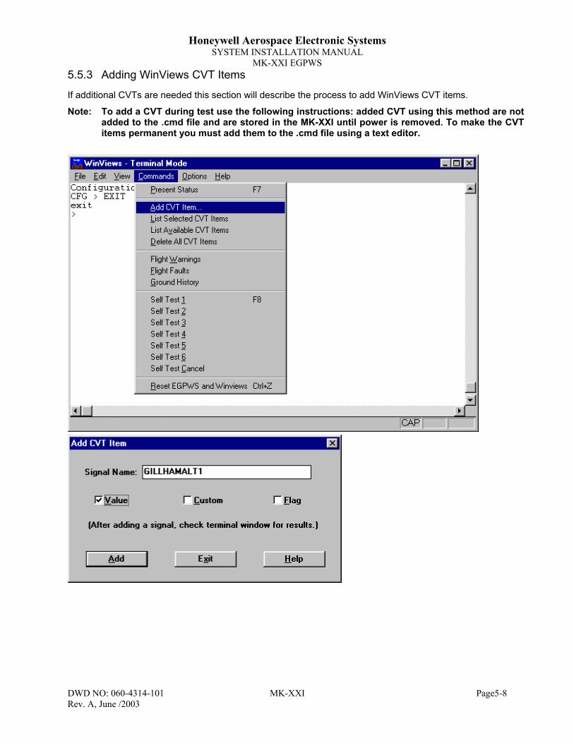
Honeywell Aerospace Electronic SystemsSYSTEM INSTALLATION MANUAL
MK-XXI EGPWS
DWD NO: 060-4314-101 MK-XXI Page5-8Rev. A, June /2003
5.5.3 Adding WinViews CVT Items
If additional CVTs are needed this section will describe the process to add WinViews CVT items.
Note: To add a CVT during test use the following instructions: added CVT using this method are notadded to the .cmd file and are stored in the MK-XXI until power is removed. To make the CVTitems permanent you must add them to the .cmd file using a text editor.

Honeywell Aerospace Electronic SystemsSYSTEM INSTALLATION MANUAL
MK-XXI EGPWS
DWD NO: 060-4314-101 MK-XXI Page5-9Rev. A, June /2003
5.5.4 Post Installation Checkout
1. Connect a PC to the RS-232 communications port of the EGPWS unit.2. Power up the PC, start “WinViews” and select connect.
Note: Ensure GPS coverage is available to the Internal GPS card/receiver or to the GPS systemproviding GPS input to the MK-XXI. You may need to move the aircraft away from hangar(in a good GPS reception area) or provide GPS information via an in-hangar GPS repeater.
3. Power up the avionics in the aircraft. You should note the “Not Available” or “GPWS INOP”light ON and you should see INITIALIZATION messages coming from the EGPWS on yourPC. When the WinViews messages quit (could be as long as 3+ minutes for the firstapplication of power (If the system has not performed the Terrain Database verificationprocedure this will take approximately 30+ minutes)) press Control ‘Z’ on your keyboard.The PC display should show a “>”.
4. Type ‘PS’ and the ‘Return’ key on your PC. You should receive several lines of statusmessages from the EGPWS. Until the PS information shows `Current Faults: No Faults’ thesystem is not operating properly. If there are system faults the PS information, under`Current Faults’ will identify the faulty sensor or input.
5. With your PC communicating with the EGPWS, select ‘File’ at the top of the WinViewsscreen. Select ‘Load Command File’ and then select the file named Hgndtst.cmd (This file isthe file created by the text editor above).
6. Select the Display Data mode by pressing the function key F6 on your keyboard. This willbring up the WinViews screen to view system inputs and internal values.
7. Set the aircraft’s altimeter to 29.92 in. Hg. and note the altitude displayed on the altimeter.Now look at the PC screen and locate the CVT item named GillhamAlt (for encoder) orRawBAlt1 (for Air data) and verify that the altitude shown agrees with the aircraft altimeter,± 200 feet. If it does not, troubleshoot the encoding altimeter / wiring or Air data source.
8. Provide a source of GPS signals to the GPS antenna. This can be accomplished by using aGPS repeater inside a hanger, or by taking the aircraft outside where it has a clear view ofthe sky.
9. Press function key F6 to return to the Terminal Mode of WinViews. Type in "GPS" followedby the ‘Return/Enter’ key to view the status of the GPS receiver. Typing Control ‘R’ on thekeyboard will re-issue the last command sent and allow you to continue to monitor GPSstatus. Once the GPS has acquired its satellites the status message “Not Navigating” willchange to “Navigation with possible data collection”. The Not Available lamp should turn offand if a display is being used, a terrain display provided by the MK-XXI EGPWS systemshould be shown on the display.
10. Press the ‘Self Test’ switch and verify that the unit lights all lamps, produces audio and thedisplay, if installed, shows a test pattern (refer to the system self test Section 5.6). TheEGPWS self test function will identify any problems with interfaces or with the EGPWScomputer. Troubleshoot any problem reported during the self test.
If installed, press the Terrain Inhibit switch and verify that the CVT item named TerrDisswitches between true and false on your PC’s display.

Honeywell Aerospace Electronic SystemsSYSTEM INSTALLATION MANUAL
MK-XXI EGPWS
DWD NO: 060-4314-101 MK-XXI Page5-10Rev. A, June /2003
5.5.5 GPS Quick Check
On the PC, select the Display Data Mode by using F6. With the system receiving GPS signals and no faultsreported, you should now verify that the system has correctly identified your closest airport. Look at thefollowing CVT items on the PC’s display:
CrwyApt The letter/number identifier of the closest airport;– Only public airports with runways 2,000 feet or longer
CRwyDist The distance in nm to the reference point of the airport;– Verify that the displayed information agrees with your geographic location
5.5.6 Air Data Check
This section will perform the necessary checks to ensure proper system input of pressure altitude.
1. Connect a pitot-static test set to the aircraft static system. Only persons trained in its useshould perform operation of the pitot-static test set. Additionally, if the aircraft static system wasopened or modified to add an encoder, the static system must be tested and approved bylicensed mechanic or authorized repairman. Improper use of the pitot-static test set can resultin damage to altimeters, vertical speed indicators etc.
2. Start with the pitot-static test set at current field elevation. Set the reference altimeter in the testset for 29.92 in. Hg.
5.5.6.1 Altitude Encoder (9 wire Gillham/Graycode altitude) Check
Note: This test is applicable if Air Data Input Select ID are #0 or 1.Record the pressure altitude indicated on the pilot altimeter - ____________PA
VERIFY the MK XXI CVT “GillhamAlt” corresponds to pressure altitude (±200ft.). << Pass/Fail ______ >>
Using an aircraft Pitot/Static System Test Set, repeat the altitude check for the current pressure altitude +500ft and +1000 ft.
Note: If configured an aural “CHECK ALT” will be heard during this test. A “CHECK ALT”annunciation will also appear on the indicator. This alert occurs due to the split between thealtitude input from the encoding altimeter and the MK XXI geometric altitude.
Record the pressure altitude indicated on the pilot altimeter - ____________PA + 500VERIFY the MK XXI CVT “GillhamAlt” corresponds to indicated altitude (±200ft.). << Pass/Fail ______ >>
Record the pressure altitude indicated on the pilot altimeter - ____________PA + 1000VERIFY the MK XXI CVT “GillhamAlt” corresponds to pressure altitude (±200ft.). << Pass/Fail ______ >>
VERIFY If configured, the aural altitude compare message, “CHECK ALT”, is enunciated and also appearson the terrain display. << Pass/Fail ______ >>

Honeywell Aerospace Electronic SystemsSYSTEM INSTALLATION MANUAL
MK-XXI EGPWS
DWD NO: 060-4314-101 MK-XXI Page5-11Rev. A, June /2003
5.5.6.2 Digital Air Data Input Check
Note: This test is applicable if Air Data Input Select ID are #2,…21.Record the pressure altitude indicated on the pilot altimeter -____________PA
VERIFY the MK XXI CVT “RawBAlt1” corresponds to pressure altitude (±200ft.). << Pass/Fail ______ >>
Using an aircraft Pitot/Static System Test Set, repeat the altitude check for the current pressure altitude +500ft and +1000 ft.
Note: If configured, an aural “CHECK ALT” will be heard during this test. A “CHECK ALT”annunciation will also appear on the indicator. This alert occurs due to the split between thealtitude input from the encoding altimeter and the MK XXI geometric altitude.
Record the pressure altitude indicated on the pilot altimeter - ____________PA + 500VERIFY the MK XXI CVT “RawBAlt1” corresponds to indicated altitude (±200ft.).<< Pass/Fail ______ >>
Record the pressure altitude indicated on the pilot altimeter - ____________PA + 1000VERIFY the MK XXI “RawBAlt1” corresponds to pressure altitude (±200ft.) << Pass/Fail ______ >>
VERIFY If configured, the aural altitude compare message, “CHECK ALT”, is enunciated and also appears onthe terrain display. << Pass/Fail ______ >>
Return the static test set and aircraft static system to local ambient pressure.
5.5.7 Outside Air Temperature Check(IF OAT PROBE IS INSTALLED)Note or add the CVT item – “TASAT”Record the current outside air temperature - __________ °CRecord the value of “TASAT” - __________ °C
VERIFY the MK XXI “TASAT” corresponds to the recorded OAT ±5°C .<< Pass/Fail ______ >>
5.5.8 Internal GPS Receiver Check
Note: Position indications from the internal GPS receiver are provided in the form of W xOy.z’ or N xOy.z’.
The EGPWS stores position as ±x.xxxO. For reference, in the EGPWS CVT item, West and South aredesignated as “-” (negative) values while North and East are designated as “+” (positive) values. To convertxOy.z’ to x.xxxO divide the y.z’ by 60 and add that value to the leading xO. For example, W 119O 36.6’ isequivalent to the MK XXI value -119.610 (or 119 + 36.6/60).
Note or add the CVT items – “GPSLatude1”, “GPSLngude1”, “RawGAlt1”, “RawHFOM1” and “RawVFOM1”.
Record the current GPS Present Position Latitude - ________( xOy.z’) / _________(±x.xxxO)
Record the value of “GPSLatude1” - ____________(±x.xxxO)
VERIFY the MK XXI “GPSLatude1” corresponds to the present latitude ±0.008. << Pass/Fail ______ >>

Honeywell Aerospace Electronic SystemsSYSTEM INSTALLATION MANUAL
MK-XXI EGPWS
DWD NO: 060-4314-101 MK-XXI Page5-12Rev. A, June /2003
Record the current GPS Present Position Longitude - ________( xOy.z’) / _______(±x.xxxO)
Record the value of “GPSLngude1” - ____________(±x.xxxO)
VERIFY the MK XXI “GPSLngude1” corresponds to the present longitude ±0.008. << Pass/Fail ______ >>
Record the Mean Sea Level (MSL) altitude of the current aircraft location - __________MSL
Record the value of “RawGAlt1” - ____________ ft
VERIFY the MK XXI “RawGAlt1” corresponds to the MSL altitude ±500ft. << Pass/Fail ______ >>
Record the value of “RawHFOM1” - ____________ nm
VERIFY the MK XXI “RawHFOM1” is <0.3 nm. << Pass/Fail ______ >>
Record the value of “RawVFOM1” - ____________ ft
VERIFY the MK XXI “RawVFOM1” is <0600 ft. << Pass/Fail ______ >>
5.5.9 DISPLAY RANGE INPUT CHECK
Note: If the Terrain Display Select ID (Category 4, Section 4.3.1.4) is 0 (KCPB) this check of rangeinput may not work. Certain KCPB displays, i.e. – GNX-Xls, use line select key presses torange up and down. If the value of “TAWxRng1” does not change and the display correctlyresponds to range commands, this check need not be performed.
Note or add the CVT item – “TAWxRng1”Select the Terrain Display on the Display (Radar Indicator or MFD)
Using the range buttons on the display, select the EGPWS Range of 10 NM.VERIFY the MK XXI “TAWxRng1” is equal to 10 NM. << Pass/Fail ______ >>
Using the range buttons on the display, select the EGPWS Range of 20 NM.VERIFY the MK XXI “TAWxRng1” is equal to 20 NM. << Pass/Fail ______ >>
Using the range buttons on the display, select the EGPWS Range to the maximum value allowed by thedisplay.VERIFY the MK XXI “TAWxRng1” is equal to the max. value in NM. << Pass/Fail ______ >>
Using the range buttons on the display, select the EGPWS Range to the minimum value allowed by thedisplay.VERIFY the MK XXI “TAWxRng1” is equal to the min. value in NM. << Pass/Fail ______ >>

Honeywell Aerospace Electronic SystemsSYSTEM INSTALLATION MANUAL
MK-XXI EGPWS
DWD NO: 060-4314-101 MK-XXI Page5-13Rev. A, June /2003
5.5.10 GPS/COM SUSCEPTIBILITY CHECK
To verify that the internal GPS receiver of the MK XXI has adequate isolation from the harmonic interferenceof the existing VHF communication transceivers each VHF transmitter will be tuned to the frequencies listedbelow and the mic keyed for a period of 20 seconds while observing the MK-XXI system status. Ensure theINOP lamp does not illuminate during each frequency check.
Tune COMM X (1, 2, 3… if installed) to each of the frequencies listed below and key the mic for 20 seconds.
VERIFY the MK XXI System Status does not go `INOP’121.150 MHz << Pass/Fail ______ >>121.175 MHz << Pass/Fail ______ >>121.200 MHz << Pass/Fail ______ >>131.250 MHz << Pass/Fail ______ >>131.275 MHz << Pass/Fail ______ >>131.300 MHz << Pass/Fail ______ >>Repeat check for each VHF Communication radio installed in the aircraft.
5.5.11 ATTITUDE & ROLL
(Note: If the Cat 10 Attitude & Heading Select ID is 0 this check need not be performed)
Varying the inputs of the Attitude system and comparing CVT Item readout to the source checks wiring to theAttitude system.1. VERIFY the Attitude Roll input per the following table:
Signal CVT Item Test Value ExpectedValue
ObservedValue
Pass Fail
Roll Angle RawRoll1 0° 0 ± 5°Roll Angle RawRoll1 15° Right Bank +15 ± 5°Roll Angle RawRoll1 10° Left Bank -10 ± 5°
Note: The test operator may choose the test value to be used. Record actual value used.Note: Positive Roll values correspond to a “Left Wing Up/Bank Right” condition.
5.5.12 MAGNETIC HEADING CHECK
Note: If the Cat. 11 Display Option Select ID is 0 this check need not be performed.
Comparing the CVT Item readout to the magnetic heading source checks the wiring to the Magnetic Headingsystem
1. VERIFY the digital Magnetic Heading input per the following table:
Signal CVT Item Test Value ExpectedValue
ObservedValue
Pass Fail
Magnetic Heading RawIMHd1 Mag Heading MH ± 5°Note: The CVT Item for Magnetic Heading is displayed as ± 180°. If the aircraft heading is
350 degrees, the CVT Item will read –10 degrees, if the aircraft heading is 240degrees, the CVT Item will read –120 degrees. If the aircraft heading is 155 degreesthe CVT Item will read 155 degrees.

Honeywell Aerospace Electronic SystemsSYSTEM INSTALLATION MANUAL
MK-XXI EGPWS
DWD NO: 060-4314-101 MK-XXI Page5-14Rev. A, June /2003
5.6 System Self-Test ProcedureThis section defines the expected information self-tests to validate the operation/installation of the MK XXIEGPWS. A high level of confidence in the MK XXI EGPWS installation can be achieved by initiating a self-test.
5.6.1 Self-Test Initiation
Self-test is initiated by pressing the TERR Test or the Self-Test switch in the pilot’s instrument panel for lessthan 2 seconds.
Note: The self-test aural volume is 6dB lower than the warning aural volume.
5.6.1.1 Self-Test Short and Long Cancel
Short cancel is accomplished by pressing and holding the test switch for less than 2 seconds.
Long cancel is accomplished by pressing and holding the test switch for 2 to 8 seconds.
5.6.2 Level 1 Self-Test
This test applies to all installations. If the installation you are testing does not include the display interfaceoption, skip to the next item.1. Verify that all of the required aircraft and avionics systems are powered and functioning.2. If the MK XXI is interfaced to a display, select a range of 40NM. If the MK XXI is interfaced through a
Terrain/Weather Radar switch ensure Terrain is selected.
Select the cockpit speaker on the audio control panel(s).Initiate the terrain self-test using the SELF-TEST switch.
VERIFY the following sequence.
1. The amber TERRAIN N/A (or TERR N/A or NOT AVAIL) light illuminates. _______(verified)2. The red WARN or TERR light illuminates. _______(verified)3. An aural “EGPWS SYSTEM OK” message is enunciated over cockpit speaker. ______(verified)4. The red WARN or TERR light extinguishes. _______(verified)5. The amber CAUT or TERR light illuminates. _______(verified)6. A terrain self-test pattern appears on the indicator. _______(verified)7. The amber CAUT or TERR light and the amber TERRAIN N/A (or TERR N/A or NOT AVAIL)
lights extinguish. _______(verified)8. The terrain self-test pattern disappears (note that the terrain display may remain on for
approximately 10 seconds after the lights extinguish). _______(verified)

Honeywell Aerospace Electronic SystemsSYSTEM INSTALLATION MANUAL
MK-XXI EGPWS
DWD NO: 060-4314-101 MK-XXI Page5-15Rev. A, June /2003
5.6.3 Level 2 Self-testNote: The TERRAIN N/A (or TERR N/A) light will be illuminated throughout this test. The Level 2 Self-
test follows the Level 1 Self-test such that the Level 1 Self-test must be performed to initiate theLevel 2 Self-test. The MK XXI “Terrain Not Available” lamp must initially be off to perform this test.
Initiate the EGPWS self-test (Level 1) using the SELF-TEST switch. Once the Level 1 self-test audiosequence begins, press and hold the test switch for less than 2 seconds. This will start Self-test Level 2.1) VERIFY the following aural messages are announced.
1. “CURRENT FAULTS” _______(verified)2. “NO FAULTS” _______(verified)3. “PRESS TO CONTINUE” _______(verified)
Note: If a EGPWS computer or system faults exist, the fault(s) will be enunciated as GPWS internal faultsand/or GPWS external faults. The aural message will provide a description of the fault(s). Any faultsthat are announced must be cleared prior to continuing the tests.
5.6.4 Self-test Level 3 - System Configuration
Note: The TERRAIN N/A light will be illuminated throughout this test.“X” denotes a number, letter, the word “point” or no enunciation. Any of these annunciations areacceptable where “X” is listed below, e.g. the serial number may be annunciated as “SERIALNUMBER “316”.)
1. Initiate the self-test (Level 1) using the test switch. Once the Level 1 self-test audio sequence begins,press and hold the test switch for less than 2 seconds. This will start Self-test Level 2.
Within 3 seconds after the “PRESS TO CONTINUE” message is enunciated at the end of the Level 2 self-test, press the test switch for less than 2 seconds.VERIFY the following aural messages are enunciated.
1. “SYSTEM CONFIGURATION” _______(verified)2. “PART NUMBER 965-1227-XXX” _______(verified)3. “MOD STATUS X” _______(verified)4. “SERIAL NUMBER XXX” _______(verified) 5. “APPLICATION SOFTWARE VERSION XXX” _______(verified)6. “TERRAIN DATABASE VERSION XXXX” _______(verified)7. “BOOT CODE VERSION XXX” _______(verified)8. “AIRCRAFT TYPE X” _______(verified)9. “AIR DATA TYPE X” _______(verified)10. “POSITION INPUT TYPE X” _______(verified)11. “TERRAIN DISPLAY TYPE X” _______(verified)12. “I.O. DISCRETE TYPE X” _______(verified)13. “AUDIO MENU X” _______(verified)14. “VOLUME SELECT X” _______(verified)15. “ALTITUDE MONITOR TYPE X” _______(verified)16. “TERRAIN DISPLAY POP-UP TYPE X” _______(verified)17. “ATTITUDE HEADING TYPE X” _______(verified)18. “DISPLAY OPTIONS TYPE X” _______(verified)19. “PRESS TO CONTINUE” _______(verified)

Honeywell Aerospace Electronic SystemsSYSTEM INSTALLATION MANUAL
MK-XXI EGPWS
DWD NO: 060-4314-101 MK-XXI Page6-1Rev. A, June /2003
6 SECTION VI - OPERATION
6.1 General InformationRefer to Section 5 of this manual for the operating instructions relating to the post installation checkout. Referto the MK-XXI EGPWS Pilot’s Guide, P/N 060-4314-100 or the aircraft’s flight manual supplement for anexplanation of the operating controls.

Honeywell Aerospace Electronic SystemsSYSTEM INSTALLATION MANUAL
MK-XXI EGPWS
DWD NO: 060-4314-101 MK-XXI Page7-1Rev. A, June /2003
7 SECTION VII – CERTIFICATION INFORMATION
7.1 IntroductionThis section outlines the procedures necessary to obtain proper certification, licensing and maintainairworthiness for the MK-XXI EGPWS System.
7.2 Certification Procedure
7.2.1 Equipment Compatibility
Careful consideration must be paid to the electrical characteristics of existing equipment or possible additionsthat will be interfaced with the MK-XXI EGPWS System, in order to ensure system compatibility. Section 3and Section 4 of this manual provide system planning guidelines, and define the electrical characteristics ofMK-XXI EGPWS System. The installing agency should contact Honeywell International Inc. Product Supportat (800) 257-0726, for information regarding the compatibility of equipment not listed in Section 4. Normalbusiness hours are 8:00 AM to 5:00 PM Central Time, Monday through Friday.
7.2.2 Equipment Location
The MK-XXI EGPWS System and associated indicators, annunciators and switches should be clearly visibleand within easy reach of the pilot. Refer to Section 2 of this manual for installation information.
7.2.3 TSO Category
The MK-XXI EGPWS complies with TSO-C151b Class B. The system must be configured for Helicopteroperation.
7.2.4 Geometric Altitude
Geometric Altitude is the MK-XXI internally calculated altitude used to determine alerts and provide the terraindisplay. Detail regarding the inputs and calculations used to create Geometric Altitude are included in theMK-XXI Pilot’s Guide.
7.2.4.1 Geometric Altitude Background
On some terrain displays, Geometric Altitude can be displayed as MSL or GSL. This altitude is the referencealtitude for the display and the terrain awareness algorithm. This reference altitude is based on internallycalculated Geometric Altitude and NOT corrected barometric altitude that must be used when navigatingwithin the National Airspace System.
Geometric Altitude is the height above mean sea level (MSL) derived from the GPS receiver, filtered by thevertical figure of merits from the same GPS and complemented by short term variations in barometric altitude.It represents the aircraft's calculated true height above MSL and serves as the reference altitude for color-coding of the terrain display and the altitude input to the look-ahead algorithm.
Because it is primarily comprised of GPS altitude, this reference altitude will often differ from cockpit displayedcorrected barometric altitude. The geometric altitude is not to be used for navigation. It is presented toprovide the crew with additional situational awareness of true height above sea level upon which terrainalerting and display is based.

Honeywell Aerospace Electronic SystemsSYSTEM INSTALLATION MANUAL
MK-XXI EGPWS
DWD NO: 060-4314-101 MK-XXI Page7-2Rev. A, June /2003
GPS altitude is an altitude above mean-sea-level and it is the geodetic height above the WGS-84 ellipsoidcorrected by the geoid height in the GPS receiver itself. With Selective Availability turned off as currently, theaccuracy is usually better than 75 feet and with Selective Availability turned on, short term accuracy is in theorder of 400 feet, but the geometric altitude should be within 100 feet.
7.2.5 FAA Requirements
The installing agency should contact a local FAA Inspector (GADO, FSDO, ACDO, MIDO, or ACO) who willdetermine whether the installation may be approved by submitting FAA Form 337,or whether a SupplementalType Certificate (STC) will be required. If FAA Form 337 is determined to be sufficient, the installing agencyshould determine the acceptability of the procedures defined within this manual. If the FAA Inspectordetermines that an STC is required, the installing agency will need to contact the nearest Aircraft CertificationOffice (ACO) to obtain acceptable procedures.
The FAA Northwest Mountain Region Aircraft Certification Office, Seattle ACO, has on file an approved reportregarding the MK-XXI EGPWS System. This report contains the bench test data and DO-160Denvironmental test data required to demonstrate the MK-XXI EGPWS System’s compliance.
7.2.6 FAA Form 337
FAA Form 337 (if applicable) must be completed and submitted to the FAA.
7.2.7 Flight Manual Revision
A Flight Manual Supplement is normally required for approval. A sample is described in Section 10-1 and canbe used as a guide to an acceptable content and format, it is not intended to apply to all installations. It is theresponsibility of the installing agency to prepare an appropriate Flight Manual Supplement, and obtain FAAapproval.
7.2.8 Pilot Briefing
The installing agency should carefully review the Flight Manual Supplement and the MK-XXI, P/N 060-4314-100, with the owner/operator of the aircraft.
7.3 License RequirementsThere are no licensing requirements for the MK-XXI EGPWS.
7.4 Instructions for Continued AirworthinessFAR Part 27.1529, AND 29.1529 Instructions for Continued Airworthiness is met per the followingInstructions:
Design and manufacture of the equipment will provide for installation so as not to impair the airworthiness ofthe aircraft.
7.4.1 MK-XXI EGPWS
If the unit should require maintenance, remove the unit and have it repaired by an appropriately ratedHoneywell approved Instrument Service Center. If the aircraft is to fly with the MK-XXI re-moved, secure theconnector(s) as necessary and placard the aircraft accordingly. After reinstallation of the unit, accomplish theappropriate Post Installation/Ground Test Checkout in Section 5.5.
During each annual or 100 hour inspection of the aircraft, perform a Level 2 Self Test of the MK-XXI asdefined in the Post Installation/Ground Test Checkout in Section 5.6.

Honeywell Aerospace Electronic SystemsSYSTEM INSTALLATION MANUAL
MK-XXI EGPWS
DWD NO: 060-4314-101 MK-XXI Page7-3Rev. A, June /2003
7.4.2 Wires/Coax Cables
During ON-Condition or regularly scheduled maintenance, inspect the wires and coax cables following theguidelines listed in AC 43.13-1B Chapter 11 as necessary.
7.4.3 Annunciators/Relays
If an annunciator bulb needs replacement, use a bulb with the same type and voltage rating as originallyinstalled. If a relay malfunctions, replace it with an airworthy relay having the same part number. If acombination annunciator/relay unit is used, e.g. MD41-1208/1308, remove the unit and have it repaired by afactory-rated service center. If the aircraft is to fly with a relay or annunciator removed, secure theconnector(s) as necessary and placard the aircraft accordingly. After re-installation of the unit, accomplish theappropriate Post Installation/Ground Test Checkout in Section 5.5.
7.4.4 GPS Antenna
If the GPS Antenna should fail, replace it with an airworthy antenna having the same part number. Verify goodelectrical bonding surfaces before installing the antenna. Ensure that antenna radome is clean and notcovered with paint. After re-installation of the antenna, accomplish the appropriate Post Installation/GroundTest Checkout in Section 5.5.
7.4.5 Temperature Probe
If the MK-XXI Self Test indicates a failure of the temperature probe, replace the temperature probe with anairworthy temperature probe having the same part number. After installation of the temperature probe,accomplish the appropriate Post Installation/Ground Test Checkout in Section 5.
7.4.6 Regional Terrain Database Updates
Regional Terrain databases can be ordered for card updates or another region by contacting:Honeywell International Inc.Aerospace Electronic SystemsOne Technology Center23500 West 105th StreetOlathe, Kansas 66061 USAAttn: Navigation Services MS-66
Telephone: (800) 247-0230 within the United States or Canada(913) 712-3145 outside of the United States or CanadaFax: (913) 712-3904
e-mail: [email protected]
See Section 5.3 for Regional Terrain Database installation and verification procedures.

Honeywell Aerospace Electronic SystemsSYSTEM INSTALLATION MANUAL
MK-XXI EGPWS
DWD NO: 060-4314-101 MK-XXI Page8-1Rev. A, June /2003
8 SECTION VIII – ABBREVIATIONS, ACRONYMS &DEFINITIONSAbbreviations, Acronyms and Definitions used in this manual.
Abbreviations/Acronyms MeaningAGL above ground levelaka also known asANSI American National Standards InstituteARINC Aeronautical Radio IncorporatedART Antenna Receiver/TransmitterASPB aka KCPB EGPWS Picture Bus InterfaceASCII American Standard Code for Information InterchangeCat CategoryCCW Counter-clockwiseConfig., CFG ConfigurationCtrl, CTRL ControlCVT Current Value Table for WinViewsCW ClockwiseEEPROM Electrically Erasable Programmable Read Only MemoryEFIS electronic flight instrument systemEGPWS Enhanced Ground Proximity Warning System (aka TAWS)FAA Federal Aviation Administration (United States)FAR Federal Aviation RequirementsFIS Flight Information Servicesfpm, FPM feet per minuteft, FT feetGPS Global Positioning SystemGSL Geodetic Sea Level (MSL) Geometric AltitudeEGPWS Helicopter Enhanced Ground Proximity Warning SystemHIRF High Intensity Radiated FieldHz HertzICAO International Civil Aviation OrganizationID IdentificationIEEE Institute of Electrical and Electronics EngineeringIFR Instrument Flight Rulesin. inchesKCPB EGPWS Picture Bus Interfacelbs. PoundsLCD Liquid Crystal DisplayLED Light Emitting DiodeRMS LRU Line Replaceable UnitMFD Multi-Function Displaymsec MillisecondMSL Mean Sea LevelmW MilliwattN.A., N/A Not Applicablenm, n.m., NM Nautical milesNTSC National Television Standards CommitteePC Personal ComputerPCMCIA Personal Computer Memory Card International Association

Honeywell Aerospace Electronic SystemsSYSTEM INSTALLATION MANUAL
MK-XXI EGPWS
DWD NO: 060-4314-101 MK-XXI Page8-2Rev. A, June /2003
Abbreviations/Acronyms MeaningPN Part NumberRF, rf Radio Frequencyrms Root mean squareRTCA Radio Technical Commission for AeronauticsRTS Return To Service (test)sec secondSW SoftwareTAWS Terrain Awareness and Warning System (aka EGPWS)TBD To Be DeterminedTSO Technical Standard OrderVAC Volts Alternating CurrentVDC Volts Direct CurrentVFR Visual Flight RulesWinViews Windows Virtual Interface to the Enhanced Warning SystemWX, Wx Weather
TABLE 8-1 LIST OF ABBREVIATIONS, ACRONYMS & DEFINITIONS

Honeywell Aerospace Electronic SystemsSYSTEM INSTALLATION MANUAL
MK-XXI EGPWS
DWD NO: 060-4314-101 MK-XXI Page9-1Rev. A, June /2003
9 SECTION IX – ENVIRONMENTAL QUALIFICATIONThe MK-XXI H-EGPWC conforms to the categories of RTCA/DO-160D “EnvironmentalConditions and Test Procedures for Airborne Electronic, Electrical Equipment andInstruments” as identified below.
Environmental Test DO160DSection Category Comments
Temperature (High/Low) 4.0 B1 Operating : -40°C to +55°CGround Survival: -55°C to +85°C
In-Flight Loss of Cooling 4.5.4 No cooling requiredAltitude 4.6.1 F2 55,000 feetDecompression 4.6.2 A2 25,000 feetOverpressure 4.6.3 A2 -15,000 feetTemperature Variation 5.0 B 5°C / min
Humidity 6.0 A 48 Hours @ 85% RH38 – 50 °C, non-operating
Shock-Operating 7.0 C Normal: 6g, 11 msec sawtooth, Low freq.: 6g, 20 msec sawtooth
Shock-Crash Safety 7.0 C 20g 11 msec sawtooth20g sustained
Vibration 8.0 U – F1 Sinusoidal: 0.1"p-p @ 5-15Hz; 0.01"p-p @ 15-55Hz,Decaying to 0.0001"p-p @ 500Hz, random 2.09grms
Explosion Proofness 9.0 E (certification)Waterproofness 10.0 X No test requiredFluids Susceptibility 11.0 X No test requiredSand and Dust 12.0 X No test requiredFungus Resistance 13.0 F No test (certification of non-nutrient material)Salt Spray 14.0 X No test requiredMagnetic Effect 15.0 Z Less than 0.3m
Power Input 16.0 B - *
Normal: 10.0 – 30.3 VDCAbnormal (5 minutes): 10.0 – 32.2 VDCEmergency (30 minutes): 18 VDCInterrupt for 200msecNormal Surge (30msec): 15 - 40VDCAbnormal Surge: 100msec @ 46.3VDC, 1sec @ 37.8VDC
Voltage Spike 17.0 A 600VDC, 10µsec, 50Ω source impedance
AF Conducted Susceptibility(Power Lines) 18.0 Z
0.20 Vrms 10-200 Hz; 0.56 Vrms, 200 – 1000 Hz1.40 Vrms, 1000 – 15,000 Hz0.20 down to .001 Vrms, 15 kHz – 150 kHz.
Induced Signal Susceptibility 19.0 Z
Magnetic, unit: 20 Arms a 400HzMagnetic, cables: 30 A-m @400Hz down to 0.8 A-m @ 15KHzElectric, cables: 1800 V-m, 380 – 420 HzInduced Spikes: 600 V p-p, 2-10µsec rate, 3 meters
RF Conducted Susceptibility 20.0 R 10 kHz – 500 kHz: 0.6mA – 30.0 mA; 500 kHz – 400 MHz: 30.0 mARF Radiated Susceptibility 20.0 RR 20 V/m, 0.1 – 0.4 GHz, SW & CW; 150 V/m, 0.4 – 8 GHz, Pulse
RF Conducted Emissions 21.0 M Power: 53 – 20 dBµA @ 0.15 – 2 MHz, 20 dBµA @ > 2 MHzCables: 73 – 40 dBµA @ 0.15 – 2 MHz, 40 dBµA @ > 2 MHz
RF Radiated Emissions 21.0 M Complex curves with notches (see DO160D Fig. 21-5)Lightning TransientSusceptibility 22.0 A3
E3Pin: 600V/24A, 300V/60ACable: 300V/600A, 600V/120A
Lightning Direct Effects 23.0 X No test requiredIcing Test 24.0 X No test requiredElectrostatic Discharge Test 25.0 A 15,000 volts
* DO-160D Section 16.0 Power Input Category B requires normal operation to 9.0 Vdc, the MK-XXI operates downto 10.0 Vdc

Honeywell Aerospace Electronic SystemsSYSTEM INSTALLATION MANUAL
MK-XXI EGPWS
DWD NO: 060-4314-101 MK-XXI Page10-1Rev. A, June /2003
10 SECTION X– CERTIFICATION DOCUMENTATIONREFERENCES
The MK-XXI EGPWS system is certified by Honeywell – AES in Redmond, WA. Certification documentationis available on the EGPWS website - http://www.egpws.com or contact:
Honeywell Aerospace Electronic SystemsBR&GA Product Support,MK XXI Product SpecialistPhone:800-257-0726
The MK-XXI system has been certified in the Honeywell AS-350 helicopter. STC documentation may beobtained by contacting the above website or Product Specialist.

Honeywell Aerospace Electronic SystemsSYSTEM INSTALLATION MANUAL
MK-XXI EGPWS
DWD NO: 060-4314-101 MK-XXI Page11-1Rev. A, June /2003
11 SECTION XI– APPROVED SENSORS
11.1 Encoding Altimeters And Blind EncodersThe following encoding altimeters and blind encoders have been tested for compatibility with the EGPWS.
Encoder Manufacturer Model No. CommentsHoneywell (Bendix/King) KEA 130A Encoding AltimeterNarco AR 850 Both 15 pin & 25 pin D versionsTrans-Cal Industries SSD 120 Blind EncodersAERO Mechanisms Inc. 8140B Encoding Altimeter
TABLE 11-1 EGPWS COMPATIBLE ENCODING ALTIMETERS & BLIND ENCODERS
Note: Various encoders have failed to pass our tests. Use of sensors other than from the above listis recommended only after confirmation of operation via the included ground test procedure.
11.2 GPS SensorsThe MK-XXI includes a built in GPS sensor. This is the preferred interface method to provide the MK-XXIsystem with position information. Many other GPS sensors may also produce an adequate GPS data set todrive the system as well.
The MK-XXI EGPWS will accept GPS data as an external input thus eliminating the need to add an additionalGPS antenna if a GPS system is already installed on the aircraft. However the specific GPS data required bythe MK-XXI currently minimizes the type of GPS systems that are compatible.
Subsequent releases of various GPS systems may facilitate adequate detail to drive the MK-XXI. Upon thattime this document will be updated to reflect the approved systems.
GPSManufacturer Model No. GPS Data
OutputRequiredFormat Comments
Honeywell(Bendix/King) KLN series Xpress Card
Data (RS-232)RS-232 KLN providing direct GPS Xpress card
output.
Garmin GNS series RS-232 RS-232 Ensure proper Garmin softwareversion level.
Misc. Misc. ARINC 429 ARINC 743 GPS data must be supplied via ARINC429 in ARINC 743 format.
Misc. Misc. ARINC 429 ARINC 743A GPS data must be supplied via ARINC429 in ARINC 743A format
Misc. Misc. ARINC 429ARINC 743(WGS-84referenced)
GPS, ARINC 429 low speed, 743format (GPS Altitude referenced toWGS-84)
TABLE 11-2 EGPWS COMPATIBLE GPS SYSTEMS

Honeywell Aerospace Electronic SystemsSYSTEM INSTALLATION MANUAL
MK-XXI EGPWS
DWD NO: 060-4314-101 MK-XXI Page11-2Rev. A, June /2003
11.3 Supported DisplaysThis Appendix previously defined the displays compatible with the MK-XXI EGPWS. Please refer to Section1-12 for the list of supported display types. The MK-XXI supports one output display bus.
It is possible that a display will work with the MK-XXI that is not on the table. If the display manufacturer hasimplemented our open architecture KCPB picture bus protocol the system may work. If the display is ARINC453 or ARINC 708 compatible it may also operate.