Aerospace and Ocean Engineering Department A New Scheme for The Optimum Design of Stiffened...
28
Aerospace and Ocean Engineering Department A New Scheme for The Optimum Design of Stiffened Composite Panels with Geometric Imperfections By M. A. Elseifi ZGürdal E.Nikola idis Sponsored in part by NASA Langley Research Center
-
Upload
silvester-parks -
Category
Documents
-
view
217 -
download
0
Transcript of Aerospace and Ocean Engineering Department A New Scheme for The Optimum Design of Stiffened...

Aerospace and Ocean Engineering Department
A New Scheme for The Optimum Design of Stiffened Composite Panels with Geometric Imperfections
By
M. A. Elseifi
ZGürdalE.Nikolaidis
Sponsored in part by NASA Langley Research Center

Aerospace and Ocean Engineering Department
Outline
Introduction
Effect of imperfections on the nonlinear response of stiffened panels.
Probabilistic and Convex Models
Current and suggested models for the uncertainty in the imperfections.
Manufacturing Model
One-dimensional curing model and process induced imperfections.
Design Optimization Problem
Results and Conclusions

Aerospace and Ocean Engineering Department
Non-Linear Elastic Behavior of Stiffened Panels
Local Postbuckling
Panel buckles into half-wavelengthsequal to the width between stiffeners.
Global (Euler) Postbuckling
Panel buckles into one half-wavelengthalong its length.
Modal Interaction
Local and global modes have equal critical loads.
Introduction
GlobalPostbucklingLocal Postbuckling
1
P/Pcr
/ cr1
ElasticLimit
ModalInteraction
Aerospace and Ocean Engineering Department
Current Scheme for Design of Panels with Imperfections(Perry, Gürdal, and Starnes, Eng. Opt. 1997)
DesiredResponse
Estimate fornominal imperfection
profile
Nonlinear analysisand design
optimization OutputDesign
+

Aerospace and Ocean Engineering Department
Geometrically Nonlinear Analysis of Stiffened Composite Panels(Stoll, Gürdal, and Starnes, 1991)
NLPAN: Non-Linear Panel Analysis,
- Finite strip method
- Linked plates of any cross-section
Displacements are assumed to have the following general form :
N
1i
N
1jijji
N
1iiiL uqququu }{}{}{}{
The imperfection shape is expressed as :
{ } { }u q uoio
ii
N
1
Aerospace and Ocean Engineering Department
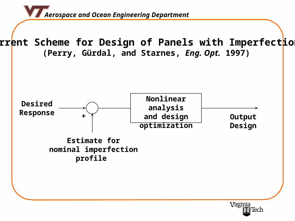
Addition of a Model for Uncertainties in Imperfections(Elseifi, Gürdal, and Nikolaidis, AIAA J., 1999)
ImperfectionModel
Estimate forImperfectionParameters
WeakestPanel Profile
+
DesiredResponse
Nonlinear analysisand design
optimization OutputDesign

Aerospace and Ocean Engineering Department
Non-probabilistic Convex Model (Ben-Haim and Elishakoff, J. of Applied Mech., 1989)
The objective is to determine the minimum elastic limit load.
Let be a vector whose components are the amplitudes of the N dominant mode shapes that represent the initial imperfection profile of the panel.
Let E ( ) represent the elastic limit load of the panel whose initial imperfection profile is given by .
Let be a nominal imperfection profile, which depends on the manufacturing process.
q
q
q
oq
N
iii
o uqu1
}{}{
Aerospace and Ocean Engineering Department
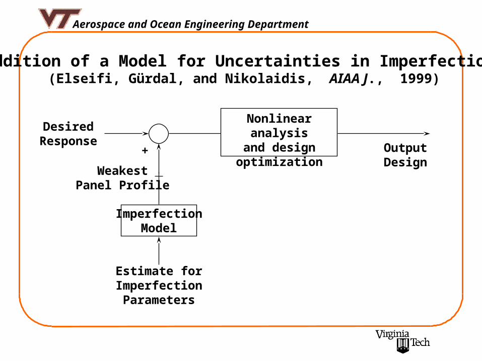
Assume that varies on an ellipsoidal set of initial imperfection spectra :
where the size parameter and the semiaxes n are based on experimental data. Thus Z () can be chosen to represent a realistic ensemble of panels.
The elastic limit for an initial imperfection spectrum to first order in is:
nq
N
n n
ooo
q
Eqq
1
)()(
N
n n
nZ1
22
2
:),(
oq

Aerospace and Ocean Engineering Department
Explicit relationship between the minimum elastic limit and the parameters defining the initial imperfections spectrum
is the elastic limit of the “weakest” panel. Z is an ensemble, which has been constructed to represent a realistic range of panels.
Evaluate the minimum elastic limit as varies on the previous convex set.
])([min),(1
),(nq
N
n n
o
Zo
q
Eq
N
nq
nn
oo
q
Eq
1
2)()(),(
q1
q2

Aerospace and Ocean Engineering Department
Probability Distribution Function of Elastic Limit for = 0.02405
0
0.2
0.4
0.6
0.8
1
1.2
Elastic Limit
Probability o
f F
ailure
Convex Model Prediction = 0.877492
oq1
Aerospace and Ocean Engineering Department
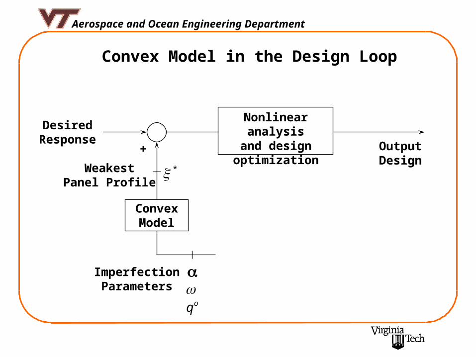
ConvexModel
ImperfectionParameters
Convex Model in the Design Loop
oq
*Weakest
Panel Profile
+
DesiredResponse
Nonlinear analysisand design
optimization OutputDesign

Aerospace and Ocean Engineering Department
ConvexModel
ImperfectionParameters
Closed Loop Design Scheme with Manufacturing Model
oq
*Weakest
Panel Profile
+
DesiredResponse
Nonlinear analysisand design
optimization OutputDesign
ManufacturingModel
DesignParameters

Aerospace and Ocean Engineering Department
One-Dimensional Curing Model for Epoxy Matrix Composites (Loos and Springer, 1983)
No resin flow (top or edge).
No energy transfer by convection.
No chemical diffusion.
No void formation.
Bleeder
Composite
Tool plate
To , Po
Lb
Li
To , Po
xz
Process Induced Imperfections in Laminated Composites(Elseifi, Gürdal, and Nikolaidis, 1998)

Aerospace and Ocean Engineering Department
Energy Equation
Hz
TK
zt
cT .)(
)(
Density of composite
c Specific heat of composite
K Thermal conductivity perpendicular to plane of composite
T Temperature of composite
H.
Rate of heat generation by chemical reaction. Function of the degreeof cure
Initial Conditions
0
)(
zTT i
0
0
t
Lz
Boundary Conditions
LzattTT
zattTT
u
l
)(
0)(

Aerospace and Ocean Engineering DepartmentP
roce
ss-I
nd
uce
d C
urv
atu
res
Sta
rt
Inpu
t
Cur
e S
imul
atio
n T
empe
ratu
re D
egre
e of
cur
e
Mic
rom
echa
nics
Inst
anta
neou
s L
amin
a P
rope
rtie
s
Pro
cess
Ind
uced
Str
ain
Incr
emen
tT
herm
al E
xpan
sion
Che
mic
al S
hrin
kage
End
Fin
al L
ocal
Cur
vatu
res
Pro
cess
Ind
uced
Mom
ent I
ncre
men
ts
tt

Aerospace and Ocean Engineering Department
Panel Profile Generation
x
yz
Mesh Point (i,j)
Only imperfections in skin.
The skin surface is discretized into a number of mesh points.
The 1-Dimensional curing simulationis applied at every mesh point.
8
1ii b
y
l
xiqw
sinsin
Curvatures-deflection relationships
8
1
2 sinsin)(i
ix b
y
l
xi
l
iq
8
1
2 sinsin)(i
iy b
y
l
xi
bq
8
1
coscos))((2i
ixy b
y
l
xi
bl
iq
Assumed imperfection profile shape

Aerospace and Ocean Engineering Department
Experimental Validation
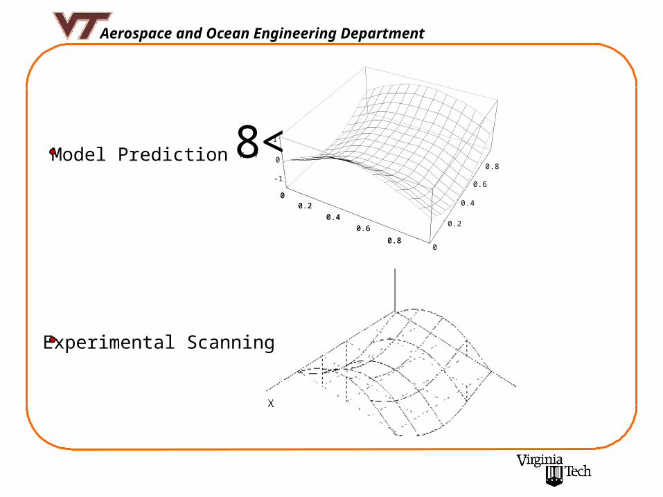
Aerospace and Ocean Engineering Department
00.2
0.40.6
0.80
0.2
0.4
0.6
0.8-1
0
18X, Y<0
0.20.4
0.60.8
Model Prediction
Experimental Scanning

Aerospace and Ocean Engineering Department
Simulation of Different Sources of Imperfection
Only uncertainties incurred in the constituent (primitive) material properties.
A random number is generated at each mesh point.
The material properties variations are assumed Gaussian.
The random numbers generated are independent from one point to the other.
Material Property
Prob. Dist.

Aerospace and Ocean Engineering Department
Results
X Y
Z
1168 mm
37 mm
178 mm
Stiffened Panel Geometry and Dimensions
Compressive Design Load : 56,000 N
Inplane Shear Design Load : 14,000 N
Material: Hercules AS4/3502 Graphite/Epoxy
Design Problem
Minimize Panel Weight : W = t ( ns As + nb Ab)
Such that : No failures for a balanced symmetric laminate

Aerospace and Ocean Engineering Department
First Proposed Closed Loop Design Scheme
Manufacturing Model
ConvexModel
Initial Population
NonlinearAnalysis
Fitness Processor
Genetic Processors
NO
NO
DesiredFailure
Load
Aerospace and Ocean Engineering Department
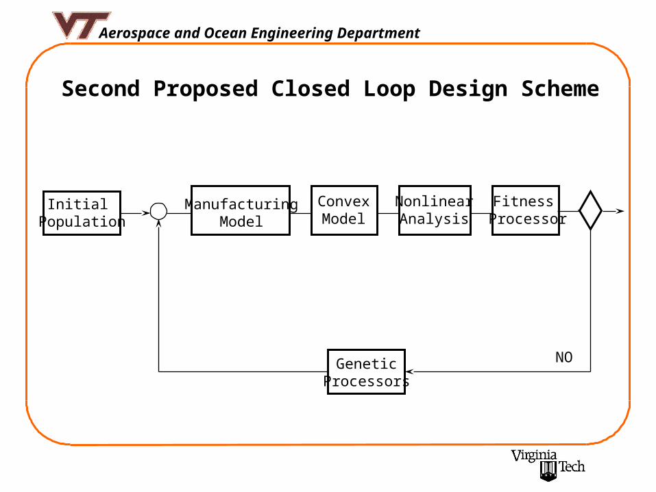
Second Proposed Closed Loop Design Scheme
GeneticProcessors
Initial Population
ManufacturingModel
ConvexModel
NonlinearAnalysis
Fitness Processor
NO

Aerospace and Ocean Engineering Department
Results of the First Design Scheme
Starting Imperfection Profile (Random)
First Optimization Result
Panel Mass(Kg)
failureP
(Newton) PliesLaminate
S: Skin B: Blade
0.523743 59500 (S)-[6]
(B)-[26]
s]0[ 3
s]45/0/90/0/90/0/45[ 62

Aerospace and Ocean Engineering Department
First Optimum Cured Profile
Failure Load : 40740 N
Second Optimization Result
Panel Mass(Kg)
failureP
(Newton) PliesLaminate
S: Skin B: Blade
0.539223 60000 (S)-[8]
(B)-[18]
s]90/45/45/0[
s]90/45/90/45/0/90/90/45/45[

Aerospace and Ocean Engineering Department
Second Optimum Cured Profile
Failure Load : 53200 N
Third Optimization Result
Panel Mass(Kg)
failureP
(Newton) PliesLaminate
S: Skin B: Blade
0.611980 60000 (S)-[10]
(B)-[16]s]90/0[ 23
s]45/45/90/0/45/0[ 2
Actual Failure Load : 56200 N

Aerospace and Ocean Engineering Department
Results of the Second Design Scheme
Panel Mass(Kg)
failureP
(Newton) PliesLaminate
S: Skin B: Blade
0.497427 57000(56320)
(S)-[10]
(B)-[4]
s]45/0/45[ 3
s]0/90[
0.535611 60000(58200)
(S)-[10]
(B)-[8]s]45/0[ 3
s]0/90/0[ 2
0.535611 57000(56520)
(S)-[10]
(B)-[8]s]45/0/45/0[ 2
s]0/90/0[ 2
Actual failure load of the optimum : 56320 N
Aerospace and Ocean Engineering Department
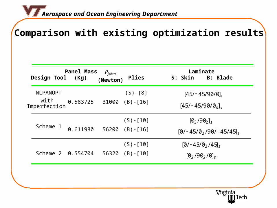
Comparison with existing optimization results
Design ToolPanel Mass
(Kg)failureP
(Newton) PliesLaminate
S: Skin B: Blade
NLPANOPT
withImperfection
0.583725 31000
(S)-[8]
(B)-[16]s]0/90/45/45[
s]0/90/45/45[ 6
Scheme 1 0.611980 56200
(S)-[10]
(B)-[16]
s]90/0[ 23
s]45/45/90/0/45/0[ 2
Scheme 2 0.554704 56320
(S)-[10]
(B)-[10]
s]45/0/45/0[ 2
s]0/90/0[ 22

Aerospace and Ocean Engineering Department
Concluding Remarks
A convex model has been introduced for the analysis of uncertainties in geometric imperfections.
A one-dimensional curing model has been extended to calculate the process-induced curvatures in epoxy matrix composite. A procedurewas suggested for the incorporation of uncertainties in the primitive material parameters as a source of imperfections.
It was shown that panels designed with empirically assumed imperfectionswere not able to carry their design load when applied along with acorresponding realistic imperfection profile.
It was demonstrated that incorporating the panel’s manufacturing information early in the design process results in panels capable of carryingrequiredloading without much increase in weight.