Aerospace & Defense Technology
58
Cov ToC + – ➭ ➮ A Intro How to Navigate the Magazine: At the bottom of each page, you will see a navigation bar with the following buttons: Arrows: Click on the right or left facing arrow to turn the page forward or backward. Introduction: Click on this icon to quickly turn to this page. Cover: Click on this icon to quickly turn to the front cover. Table of Contents: Click on this icon to quickly turn to the table of contents. Zoom In: Click on this magnifying glass icon to zoom in on the page. Zoom Out: Click on this magnifying glass icon to zoom out on the page. Find: Click on this icon to search the document. You can also use the standard Acrobat Reader tools to navigate through each magazine. Welcome to your Digital Edition of Aerospace & Defense Technology June 2014 ➭ Intro Cov ToC + – A www.aerodefensetech.com Using Forensic Lasers in Modern Warfare Europe’s Aerospace Industry Looking Confident Comparing Blade-Element Momentum Modeling to 3D CFD Open Generic Avionics Architectures Using Ethernet and VPX Supplement to NASA Tech Briefs June 2014
Transcript of Aerospace & Defense Technology

Cov ToC + – ➭
➮
AIntro
How to Navigate the Magazine:
At the bottom of each page, you will see a navigation bar with the following buttons:
Arrows: Click on the right or left facing arrow to turn the page forward or backward.
Introduction: Click on this icon to quickly turn to this page.
Cover: Click on this icon to quickly turn to the front cover.
Table of Contents: Click on this icon to quickly turn to the table of contents.
Zoom In: Click on this magnifying glass icon to zoom in on the page.
Zoom Out: Click on this magnifying glass icon to zoom out on the page.
Find: Click on this icon to search the document.
You can also use the standard Acrobat Reader tools to navigate through each magazine.
Welcome toyour Digital Edition ofAerospace & Defense
TechnologyJune 2014
➭
Intro
Cov
ToC
+
–
A
www.aerodefensetech.com
Using Forensic Lasers in Modern Warfare
Europe’s Aerospace Industry Looking Confident
Comparing Blade-Element Momentum Modeling to 3D CFD
Open Generic Avionics Architectures Using Ethernet and VPX
Supplement to NASA Tech Briefs
June 2014

© Copyright 2013–2014 COMSOL. COMSOL, COMSOL Multiphysics, Capture the Concept, COMSOL Desktop, and LiveLink are either registered trademarks or trademarks of COMSOL AB. All other trademarks are the property of their respective owners, and COMSOL AB and
ELECTRICALAC/DC ModuleRF ModuleWave Optics ModuleMEMS ModulePlasma ModuleSemiconductor Module
MECHANICALHeat Transfer ModuleStructural Mechanics Module Nonlinear Structural Materials ModuleGeomechanics ModuleFatigue ModuleMultibody Dynamics Module Acoustics Module
FLUIDCFD ModuleMixer ModuleMicrofluidics ModuleSubsurface Flow ModulePipe Flow ModuleMolecular Flow Module
CHEMICALChemical Reaction Engineering Module Batteries & Fuel Cells ModuleElectrodeposition Module Corrosion ModuleElectrochemistry Module
MULTIPURPOSEOptimization ModuleMaterial LibraryParticle Tracing Module
INTERFACINGLiveLink™ for MATLAB®
LiveLink™ for Excel®
CAD Import ModuleECAD Import ModuleLiveLink™ for SolidWorks®
LiveLink™ for SpaceClaim®
LiveLink™ for Inventor®
LiveLink™ for AutoCAD®
LiveLink™ for Creo™ ParametricLiveLink™ for Pro/ENGINEER®
LiveLink™ for Solid Edge®
File Import for CATIA® V5
Product Suite
COMSOL Multiphysics
®COMSOL MULTIPHYSICSVERIFY AND OPTIMIZE YOUR DESIGNS WITH
Multiphysics tools let you build simulations that accurately replicate the important characteristics of your designs. The key is the ability to include all physical effects that exist in the real world. To learn more about COMSOL Multiphysics, visit www.comsol.com/introvideo
WAVE OPTICS: Model of a directional coupler formed from two interacting waveguides.
VERIFY AND OPTIMIZE YOUR ESIGNS WITH
Free Info at http://info.hotims.com/49746-817
Cov ToC + – ➭
➮
AIntro

www.aerodefensetech.com
Using Forensic Lasers in Modern Warfare
Europe’s Aerospace Industry Looking Confident
Comparing Blade-Element Momentum Modeling to 3D CFD
Open Generic Avionics Architectures Using Ethernet and VPX
Supplement to NASA Tech Briefs
June 2014
Cov ToC + – ➭
➮
AIntro

Wireless InSite is a suite of ray-tracing models for analyzing EM propagation and communication channel characteristics in complex urban, indoor, rural and mixed path environments.
Remcom’s Wireless InSite®
Radio Propagation Software for Wireless Communication Planning
See all the latest enhancements at www.remcom.com/wireless-insite-features
Now integrated with the Geospatial Data Abstraction Library (GDAL).
� Indoor WiFi
� Moving vehicle or aircraft
� LTE and WiMax throughput analysis
� Tower placement for urban coverage
� Ad-hoc and temporary networks
� Base station coverage analysis
� Microcell coverage
Wireless EM Propagation Capabilities for a Variety of Applicationsiety of Applications
+1.888.7.REMCOM (US/CAN) | +1.814.861.12999www.remcom.com
Visit Us at IMS 2014Booth #1105.
Cov ToC + – ➭
➮
AIntro
Free Info at http://info.hotims.com/49746-780

No company in the embedded computing space covers the breadth of products and services that Elma does, and we pass that advantage on to you. We consider ourselves an extension of your team -- we fill in where you need us most.
Our customers work with us for our expertise in packaging, our clear understanding of thermal issues and years of experience in building integrated, embedded sub-systems.
We can be relied on for all aspects of project – from the initial design expertise, documentation & technical support, simplified procurement, to end of lifecycle management.
From a single component up to a fully integrated embedded sub-system, we can be there at any or every step of the way.
Find out why Elma is truly Your Solution Partner.
Work with an embedded computing partner you can count on
Free Info at http://info.hotims.com/49746-781
Cov ToC + – ➭
➮
AIntro
2 Aerospace & Defense Technology, June 2014Free Info at http://info.hotims.com/49746-782
Aerospace & Defense Technology
ContentsFEATURES ________________________________________
6 Lasers & Optics6 Using Forensic Lasers in Modern Warfare
12 Rugged Computing12 Open Generic Avionics Architectures and Distributed
Processing Using Ethernet and VPX
20 Testing and Simulation20 Comparing Blade-Element Momentum Modeling to 3-D CFD
24 European Aerospace Programs24 Europe’s Aerospace Industry Looking Confident
29 RF & Microwave Technology 29 Advances and Challenges in Developing Radar Applications34 Simulation Tools Prevent Signal Interference on Spacecraft
42 Tech Briefs42 Manufacturing Robotic Tools for Piping Inspection and Repair43 Fabricating Porous Systems for Super-Dense Memories and
Sensors44 Design and Fabrication of a Radio Frequency Grin Lens Using
3D Printing
45 Preparing Carbon-Coated Current Collectors for High-PowerLithium-Ion Secondary Batteries
DEPARTMENTS ___________________________________
4 What’s Online36 Technology Update47 Application Briefs50 New Products52 Advertisers Index
ON THE COVER ___________________________________
The U.K. aerospace industry has a major share inthe production of the F-35B (shown), including itsrear fuselage, fin assemblies, and ejector seats. Tolearn more about Europe's growth in the develop-ment of defense and commercial aircraft, read thefeature article on page 24.
(Image Credit: Crown copyright, Ministry of Defence)
Cov ToC + – ➭
➮
AIntro

Free Info at http://info.hotims.com/49746-783
Cov ToC + – ➭
➮
AIntro

4 www.aerodefensetech.com Aerospace & Defense Technology, June 2014
What’s Online
Top ProductsIntegrated Servo Motor
Designed for battery-powered andlow-voltage applications, the MAC402from JVL is the VDC version of theMAC400 400-W integrated servomotor. The supply range for theMAC402 is 12 to 48 VDC, and fullpower of 400W (RMS) up to 1200W(peak) can be reached with 24 to 48VDC. This powerful, compact motormeasures 191 × 60 × 114 mm. Applications include, but are notlimited to, remotely operated robots, robotic vehicles, portableequipment, tracking devices, antenna mounts, and positioningdevices. More detail at http://articles.sae.org/12836.
Nano Circular ConnectorTE Connectivity’s CeeLok FAS-T nano circular connector is
a nano-miniature, rugged I/O connector capable of meeting10 gigabit Ethernet performance. The proven, noise-cancelingcontact configuration minimizes crosstalk, making it suitablefor a variety of markets and applications, including missiles,UAVs, soldier systems, and C4ISR. The connector provides ahigh-speed/bandwidth I/O connector in a form factor that oc-cupies less than 3/8 in of panel space. More detail at http://articles.sae.org/12837.
PEEK Wear CompoundsThe LUVOCOM 8000 series of PEEK wear compounds from
Lehvoss North America incorporates proprietary additivesthat further elevate the wear resistance of PEEK compounds.Through research and testing, Lehvoss designed the LUVO-COM 8000 product line to have a tribological profile signifi-cantly surpassing previously known materials while also pre-serving mechanical performance. More detail at http://articles.sae.org/12835.
Wire Grid PolarizersHigh-contrast IR wire grid polarizers from Edmund Optics
are suited for broadband IR applications that require hightransmission and contrast, including spectroscopy and ther-mal imaging. The polarizers are made by applying a thin layerof aluminum microwires to a glass window. They are designedusing a lightweight, thin silicon substrate, making them wellsuited for weight-sensitive systems such as unmanned aerialvehicles. More detail at http://articles.sae.org/12793.
Voltage Controlled OscillatorCrystek’s CVCO25CL-0902-0928 VCO operates from 902 to
928 MHz, with a control voltage range of 0.5 to ~3.5V. It featuresa typical phase noise of -108 dBc/Hz @ 10 kHz offset and has ex-cellent linearity. Output power is typically +3 dBm. The model ispackaged in the industry-standard 0.5- × 0.5-in SMD. Input volt-age is 3V, with a max. current consumption of 15 mA. Pullingand pushing are minimized to 0.5 MHz and 0.5 MHz/V, respec-tively. More detail at http://articles.sae.org/12795.
Top Articles Dassault Magnifies Focus on Its 5X
In the latest iteration of the EASy flight deck on DassaultAviation's new 5X business jet, the immediate priorities areseparated out from follow-up actions required later during theflight when presenting data for managing safe flight. Readmore at http://articles.sae.org/12872.
Boeing Advances Automation with Smart and PortableOrbital Drilling Tools for 787
Boeing makes a leap forward in manufacturing automationwith a portable orbital drilling tool that is, at its core, indistin-guishable from a fully autonomous robotic system. Read moreat http://articles.sae.org/12811.
Government-Sanctioned Test Site Opens Up Airspace forMIT Researchers
MIT classes and researchers developing unmanned aerialvehicles and their associated systems will be able to take ad-vantage of a new FAA-designated facility located at Joint BaseCape Cod. Read more at http://articles.sae.org/12993.
Architecture Developed for Monitoring and AnomalyDetection of Space Systems
Researchers at the University of Central Florida have foundthat by incorporating analysis and monitoring algorithms,such as Inductive Monitoring System, neural networks, andrecent advances in deep learning within the architecture’s sig-nal processing system, engineers have a flexible and powerfulend-to-end data analysis and monitoring system for instru-mented remote aerospace hardware. Read more at http://articles.sae.org/12861.
Maintenance Tools for Improved Engine BearingA number of advanced bearing maintenance products, such
as customized induction heaters and sophisticated thermalcameras, can help aircraft engine OEMs and maintenanceproviders meet such exacting standards. Read more athttp://articles.sae.org/12864.
The Falcon 5X underwent its first simulated flight, completing an importantmilestone in the development program, in November 2013.
Cov ToC + – ➭
➮
AIntro

From Down Hole ... to Deep Space
Constructed of specially-engineered materials, our inductors withstand environments unsuitable for commercial-grade products.
• Air-core inductors with a temperature range from -60°C to +240°C
• Power inductors with a range of -55°C to +200°C• Extreme-temperature coil designed for tempera-
tures up to 300°C!
From extreme heat to severe cold, we have the RF and power magnetics to handle your harshest environments
800.981.0363 847.639.6400 www.coilcraft-cps.com
We also offer power inductors that pass vibration and shock testing to 80 G and 1000 G respectively, as well as a broad range of products that meet NASA low outgassing specifications.
Learn more about Coilcraft CPS’s extreme environment products. Call or visit us online today!
Free Info at http://info.hotims.com/49746-786
Cov ToC + – ➭
➮
AIntro

6 www.aerodefensetech.com Aerospace & Defense Technology, June 2014
In the conflicts in Iraq andAfghanistan, the enemy’s guerillatactics have muddled the distinc-tion between terrorism and war-
fare. To deal with the challenges of thisnew type of combat, the military hasquietly built up impressive forensic ca-pabilities, with technology more usu-ally found in domestic crime labs thanon the battlefield. Just as they have innumerous areas of weapons technology,lasers play a cutting-edge role in thiswork, which is performed on location,within mobile labs in Afghanistan, aswell as in the US.
The main military use of forensiclasers is to find latent fingerprints on avariety of different substrates. This ef-fort is targeted at tasks, such as identi-fying those who have handled an IED(improvised explosive device), and de-termining those responsible for its cre-ation. This can be accomplished byexamining the components of thesedevices either before or after explo-sion. Another reason for lifting printsis to establish the identity of individu-als who may have handled a weaponin the commission of a crime, or totrack the provenance of counterfeitdocuments.
Laser-Excited FluorescenceProven in non-military forensics,
green lasers (532 nm wavelength) areworkhorse tools, used primarily for lo-cating and imaging latent fingerprintsvia laser-excited fluorescence. This canbe accomplished on both porous andnon-porous surfaces. Fluorescence oc-curs when a bright light, such as a laser,illuminates certain materials (such assweat and finger oil), and some of thelight is re-emitted at a longer wave-length. Because the laser illuminationand fluorescence are different colors,optical filters can be used to separatethem. Specifically, a filter which blocksthe laser light but transmits the fluores-cence significantly enhances the con-trast of the print, allowing it to beviewed and photographed (Figure 1).
Sometimes a print can be imaged inthis way with no chemical pre-treating.That is because many organic materials,including lipids and proteins, exhibitweak natural fluorescence, called inher-ent fluorescence. But, while high ambi-ent temperatures in Afghanistan causeincreased likelihood of sweating, thusyielding prints containing more bodilyfluids, in most cases the substrates haveto be treated with a fluorescent dye ac-
cording to standard protocols used byforensic/CSI labs and domestic law en-forcement groups.
In this protocol, the substrate is first ex-posed to superglue fumes, which prefer-entially bind to the lipids and other traceorganics and inorganics in a print. Thesurface is then exposed to the highly flu-orescent Rhodamine 6G dye, which clingspersistently to the ethyl or methyl cyano-acrylate (superglue). As a result, whenviewed through the wavelength selectiveglass filter, the print can be literally thou-sands of times brighter (Figure 2) than anyscattered laser illumination light.
The Evolution of Forensic LasersCrime labs originally developed this
application using blue (488 nm) and/orblue-green (514 nm) output from argonion lasers. But these large, delicate, andpower-hungry lasers required a 220-voltpower supply and water cooling, mak-ing them impractical for field use. Be-cause of these limitations, crime sceneswere instead “swept” with an alterna-tive light source (ALS) in order to excitefluorescence, even though the ALS usu-ally delivered inferior results to a laser.In spite of its cryptic acronym, an ALS isactually no more than just a bright
Using Forensic Lasers in Modern Warfare
Major Steve Ranieri, the Brigade Judge Advocate for 1st Adviseand Assist Brigade, 3rd Infantry Division, looks at a drink canunder a laser used to show fingerprints not visible under normalconditions. (Photo Credit: Pvt. Emily V. Knitter, 1/3 AAB, USD-C)
Cov ToC + – ➭
➮
AIntro

Aerospace & Defense Technology, June 2014 7Free Info at http://info.hotims.com/49746-785
Lasers & Optics
lamp whose output is passed through an optical filter, some-times with fiber coupling to a handpiece.
The advent of compact visible lasers, based on diode-pumped, solid-state (DPSS) technology with green (532 nm)output, enabled the first portable laser applications. But thesecrystal-based lasers were often too expensive, and still notrugged enough for crime scene work, let alone field use by themilitary. The situation completely changed with the develop-ment of optically pumped semiconductor laser (OPSL) tech-nology. This enabled the construction of highly compactgreen (and other wavelength) lasers, with power consumptionlow enough to even enable battery operation. And becauseOPSL technology can be readily made immune to shock andvibration, forensic lasers based on this technology provide the24/7 rugged reliability needed for demanding field use, toughhandling, and high-throughput screening.
A View from the FieldChere S. Reynolds is a former civilian military contract em-
ployee who recently completed a third deployment toAfghanistan (two at Kandahar and one at Bagram) as a LatentPrint Processing Technician. Reynolds explains the need for highthroughput at these sites, “Most IEDs incorporate a lot of adhe-sive tape. For some cases, our lab often would have to processover 1000 pieces of tape, looking for latent prints on both the ad-hesive and non-adhesive side. Yet, sometimes we’d be allocatedas little as 48 hours per case. We’d first perform an inherent examof the tape or other evidence, that is, without using any chemicaltreatment to develop and reveal latent prints. We’d then mostcommonly do a standard dye and laser exam. During my first de-ployment in 2011, we switched from illuminating the dye usingan ALS to using a green Optically Pumped Semiconductor Laser(OPSL). The number and quality of prints we obtained shot updramatically with laser excitation.”
The reasons for this difference are well documented. First,the laser has much higher monochromaticity (wavelength
Figure 1. A filter which blocks the laser light but transmits the fluorescence sig-nificantly enhances the contrast of the print, allowing it to be viewed and pho-tographed.
(Continued on page 10)
Cov ToC + – ➭
➮
AIntro

Benefits
Reduces program risks to schedule, budget,and deliverables
Improves program performance with asingle verification management system
Increases traceability of requirements fromprogram through design, analysis,and test
Reduces verification costs with improvedplanning and execution
Enables proactivemanagement ofrequirement compliance with real-time reporting
Accelerates program audits with accurate,up-to-date, documenteddeliverables andactivities
A&D firms achieve program excellence with Siemens integrated verification management.Integrating virtual and physical testing enables delivery of products on schedule and on budget.
The complexity of aerospace and defense (A&D) products and the number of require-ments that they must meet to gain customer or regulatory acceptance continues to grow. As a “system of systems” comprised of soft-ware, hardware and electronics, A&D products involve lengthy, multidisciplinary development programs and interrelated verification activi-ties to gain customer or regulatory agency ap-proval. Whether it’s a commercial airliner, weapons platform or a spacecraft, failure is not an option.
A&D companies compete in a global market place and execute programs with multiple global partners and suppliers. To be successful in this environment, A&D companies must demonstrate their ability to consistently execute programs across the extended organization, delivering products that meet requirements on-schedule and on-budget.
The Siemens PLM Software Verification Management solution enables companies to achieve this goal by connecting requirements to all tasks, analyses, tests and data involved
in the requirement verification process, providing complete visibility and traceability across planning, design, analysis, test, and final compliance reporting.
Providing full lifecycle traceability
Programs must meet requirements that are set by their customers, contained in their contracts, and meet company product standards for design and safety, as well as industry requirements from regulatory authorities such as the Federal Aviation Administration (FAA) and the European Aviation Safety Agency (EASA). Teamcenter® software from Siemens PLM Software enables all program activities to be driven by these requirements, from initial program goals to the individual components that will make up the final product. With Teamcenter, full product lifecycle traceability makes it possible to ensure that all requirements have an approved verification method, that the method is executed, and that appropriate results are recorded to support achievement of the requirements.
8 www.aerodefensetech.com Aerospace & Defense Technology, June 2014
ADVERTISEMENT
Cov ToC + – ➭
➮
AIntro

Features
Requirements management
Verification planning and execution
System analysis and test
Schedule management
Change management
Configuration management
Test article and equipment definition and history
Synchronizing analysis from design through test
Teamcenter is a full product lifecycle solution that can communicate requirements to all disci-plines in the product development process as well as changes to those requirements. This sin-gle collaborative source permits design, analy-sis, and test organizations to work in unison to ensure that analysis and simulation models are synchronized with design models for both pro-duction and test articles, and that physical test articles conform to requirements across disci-plines. By synchronizing these models, simula-tions representing the production design - as well as all the modifications made to the test article - remain valid for proving requirements are met. Teamcenter also provides integration of analysis-to-analysis (an often-overlooked fail-ure point) by managing the process to take the outputs from one analysis and them as inputs to the next analysis, as well as all the other arti-facts required to conduct the next analysis; other boundary conditions or inputs, models,etc. Only in this way are design analy-ses and tests truly integrated and connected.
Tracing the test to the physical test article
Physical tests are a necessity for aerospace and defense products, and it’s imperative that tests prove that requirements are met. Proving a test valid requires that a sequence be fol-lowed from requirements to be verified to test plans that define the verification approach and that test articles and equipment are config-ured properly. Teamcenter establishes the path from requirements to test plans to test article to confirm that a test is required, prop-erly planned, and accurately executed. If changes in requirements or the product design occur, Teamcenter can be used to immediately provide full visibility of their impact on plans, test articles, and tests - including those already run that need to be re-executed.
Teamcenter also maintains the complete history of all test articles and equipment, enabling full traceability to the past test article or analytical model configurations. In addition, Teamcenter provides complete instrumentation traceability: from measurement requirements defined by en-gineering in the test request; to the instrumenta-tion plan; to the physical instrument installed on the test article and its calibration data through to the raw data and the reduced engineering unit data used for reporting compliance.
Full traceability enables the ability to demon-strate that the test article matches the current engineering definition as well as the original production design at every stage.
Integrating the verification management system
Moving from planning what to do, to actually doing requires task definitions, scheduling, and management. Teamcenter provides this func-tionality for all verification activities to link engineering, manufacturing, procurement, and test to support long lead planning, resource uti-lization and execution of the verification activi-ties. Verification requirements are linked to supporting documentation for virtual and phys-ical test configurations, test plans, test proce-dures and test results to enable complete status reporting of the process. This holistic approach ensures efficient usage of resources and pro-vides visibility into the process to ensure that deadlines are met. Requirements can be linked to activities on the verification management schedule as well as to a Work Breakdown Structure for correlation to financial reporting
systems; integrating cost, schedule, and techni-cal requirements in a single system.
Conclusion
The Verification Management solution in Teamcenter empowers A&D companies to suc-cessfully execute their programs on-schedule and on-budget by providing visibility and closed-loop requirement traceability into all activities of the verification process to confirm requirement compliance. With efficient plan-ning, simulation, analysis and test execution in an integrated environment enabling confirma-tion of requirements achievement, Teamcenter supports program audits and reduces the time and cost of verification that ultimately improves program performance.
by David Riemer
www.siemens.com/plm
ADVERTISEMENT
Free Info at http://info.hotims.com/49746-784Aerospace & Defense Technology, June 2014 9
Cov ToC + – ➭
➮
AIntro

10 www.aerodefensetech.com Aerospace & Defense Technology, June 2014
Lasers & Optics
brightness) than an ALS. Second, italso has higher spatial brightness, mak-ing it easy to direct all of the laser’soutput into a small area, usually bymeans of a fiber optic connectedhandpiece. Together, these result inbrighter fluorescence. Moreover, alaser also offers a time/speed advan-tage; it is ideal for single-sweep work,whereas optimum use of an ALS oftenrequires multiple sweeps with differentfilter settings.
To deal with their high volume ofwork, the military now uses approxi-mately twenty green lasers; these TracERlaser systems are manufactured using
Coherent’s patented OPSL technology,and are supplied to the military by spe-cialty US distributor Arrowhead Foren-sics. Some of these laser systems incor-porate a rechargeable battery pack forfield portability. The battery pack hasthe added advantage of making the laserimmune to frequent power interruptionsdue to the lack of infrastructure in over-seas power grids, such as in Afghanistan.
Rugged Reliability and Immunity toVibrations
The semiconductor reliability ofOPSLs has certainly been put to the testin this military work, particularly at the
bases in Afghanistan. Reynolds ex-plains that, “The mobile labs are podsbased on standard 40 foot ‘conex’ trans-shipment containers, with bump-outsides. The outdoor temperature canvary from well below freezing to over120°F. The lab heaters are hard to con-trol, and the lab temperature could dropdown below 40°F and then surge to the80°F to 90°F range. And, because one ofour labs was on a second story, thenearby landing and take-off of fighterjets caused major vibrational issues.Yet, we never had a laser head shift outof optimum alignment or fail in spite ofall these very challenging operatingconditions.”
SummaryWhile lasers have certainly estab-
lished their place in modern warfare,particularly in the areas of targeting,guidance, and countermeasures, theyare also now quietly playing a key en-abling role in a very different aspect oftoday’s military conflicts. In particu-lar, in an age when opposing forcesoften consist of irregulars and insur-gents, rather than a clearly identifiedarmy, they can aid in positively identi-fying the enemy. Furthermore, as thiswork shows, these advanced lasershave proven the ability to perform thistask under the most harsh and extremeconditions.
This article was written by MarkKeirstead, Coherent Inc. (Santa Clara, CA)and Brad Brown, Arrowhead Forensics(Lenexa, KS). For more information, visithttp://info.hotims.com/49746-501.
Forensic scientist Lisa Carson examines a fingerprint treated with Rhodamine and illuminated with a laser.The Rhodamine causes the print to fluoresce under the laser. (Photo Credit: Ms. Elizabeth Lorge (ARNEWS))
Figure 2. One of the advantages of green (532 nm) laser light is that it generates high fluorescence intensity. On this Rhodamine-dusted aluminum foil, this allowsthe camera aperture to be greatly reduced to obtain sufficient depth of focus for this highly contoured surface (left). This same dusted print could not be seenwith an ALS (center), even with an extended exposure time with the ALS (right).
(Continued from page 7)
Cov ToC + – ➭
➮
AIntro

Siemens PLM Software: Smarter decisions, better products.
A simple idea inspired this product. Thousands of decisions made it real.©
20
14
Sie
men
s Pr
od
uct
Lif
ecyc
le M
anag
emen
t So
ftw
are
Inc.
All
rig
hts
res
erve
d.
Siem
ens
and
th
e Si
emen
s lo
go
are
reg
iste
red
trad
emar
ks o
f Si
emen
s A
G.
All
oth
er lo
go
s, t
rad
emar
ks o
r se
rvic
e m
arks
use
d h
erei
n a
re t
he
pro
per
ty o
f th
eir
resp
ecti
ve o
wn
ers.
Answers for industry.
Making a great product takes more than inspiration. It takes thousands of decisions for a good idea to become real. Not just the big milestone decisions, but all the small decisions that lead up to them. The fact is, anyone can make the decision that makes the difference in your product’s success.
For leading companies throughout the world, Siemens PLM Software is an essential environment for immersive product decision-making. Our solutions give everyone involved in making your products “high-definition PLM.” HD-PLM ensures that people get the information they need, when they need it—with absolute clarity—to make more informed decisions faster.
No matter what industry you’re in—automotive or aerospace, electronics or energy, marine or medical, machinery and more—Siemens PLM Software helps you make the smart decisions that go into making great products. Learn more at siemens.com/plm.
Siemens PLM Software provides an immersive decision-making environment that understands the cross-functional dependencies in your product lifecycle process. This gives everyone the right information in the right context to make the right decisions.
Free Info at http://info.hotims.com/49746-818
Cov ToC + – ➭
➮
AIntro

12 www.aerodefensetech.com Aerospace & Defense Technology, June 2014
Rugged Computing
Open Generic Avionics Architecturesand Distributed Processing UsingEthernet and VPX
The backplane and hardwaremodule standards help to in-crease part commonality andthe reuse of components in dif-
ferent system architectures and applica-tions, but this is only one part of the sys-tem design challenge. While the specifiedfootprint, backplane format, and electri-cal signal characteristics help the designof modular hardware and open architec-tures, they still tell very little about howmodular (and unambiguous) the interfac-ing among functions and their interac-tions are. This aspect is covered at the sys-tem integration (network) layer.
VPX, as a switched fabric, supportsthe design of advanced integrated sys-tems using technologies such as deter-ministic Ethernet, which can be used inbackplane and backbone applications.In cases where functional interrelation-ships and Ethernet network bandwidthsharing is deterministic and all logicallinks among critical function have con-figurable quality of service with guaran-teed timing, the complexity challengesin design of advanced integrated archi-
tectures can be much simpler to handleand mitigate. This enables design oftruly open and flexible modular embed-ded systems, which can host hard real-time, real-time, and soft functions atlower system lifecycle costs. Incremen-tal modernization is fully supported,and new functions can be added with-out influencing already integrated ones.
VME and the VPX MarketVME has been used for over 30 years
in different industries, and its latestVME64 64-bit backplane can move40MByte of data per second betweenplugged cards. Over the years, many ex-tensions have been added to the VMEinterface (VME64x), providing “side-band” channels of communication inparallel to VME itself, to enhance band-width capabilities.
VPX (ANSI/VITA 46.0-2007) is posi-tioned as a VME successor and backplanestandard for design of rugged modularsystems, designed by the VITA and its100+ members. The VME embedded mar-ket today in aerospace and defense appli-
cations is estimated to be $600M (~20% isVPX). The difference in market numberscomes from the fact that VME boards areused for upgrades to existing systems,while VPX is used in new designs.
The VPX standard enables integrationof high-speed serial switched fabric in-terconnects such as PCI Express, Ra-pidIO, Infiniband, and 10 Gigabit Eth-ernet to satisfy high bandwidth re -quirements in a minimized footprint.Around this VITA (www.vita.com) stan-dard, an ecosystem of COTS productshas developed since 2008, with over400 board products provided by majorCOTS board suppliers, such as Curtiss-Wright, GE IP, Kontron, Mercury, andover 30 other suppliers.
VITA 68 Bandwidth Extensions forVPX Backplane
As VPX was designed, the networkbandwidth was significantly lower formany of the networking technologiesused only 7-8 years ago. VITA 68 was in-troduced to support the integration ofextended bandwidth and integrity guar-
VPX RackVPX Computing Modules
VPX EthernetSwitches
VPX Ethernet
Switch(es)
S1
S2EEttherneettBackbbooneeNNNeeetttwwwooorrrrkkk
EthernetBackboneNetwork
VVPVV XPPEEEttthhheeerrrnnrrr ett
BBaaaccckkkpppkkkk lllane
VPXEthernet
BackplaneCM3
CMn
CM1
CM2
RapidIO,O PCICC e,eInfn iff nii ibii and,dd
10GEthernrr etBackpkk lane
RapidIO, PCIe, Infiniband,
10GEthernetBackplane
CMe2
CMeN
CMe1
......
CM: VPX C omputing M odule CMe: External Computing ModuleRIO: Remote IO S1, S 2: VPX E thernet S witches
CM: VPX Computing Module CMe: External Computing ModuleRIO: Remote IOS1, S2: VPX Ethernet Switches
RIO
Figure 1. Logical View of VPX Backplane with external Ethernet backbone, computing modules, and remote IO.
Cov ToC + – ➭
➮
AIntro

3M DefenseProblem. Solved.
Make helo blades more durable and repairable on-site in minutes. Because out here, minutes matter.
3M™ co-cure solutions make helicopter blades stronger and repairable on-site. That means blades last longer. It means no
more removing and shipping blades when they need minor repair or resurfacing. It means fewer extra blades laying around. All of
which helps save valuable maintenance time and money. For the military, both are at a premium. At 3M Defense, that’s just what we do.
We solve the military’s toughest problems by drawing from our vast resources: people, technologies, products and processes.
Find out how incorporating 3M co-cure technology into your aircraft can help keep you flying longer at 3Mdefense.com/aerospace.
© 3
M 2
014.
All
Righ
ts R
eser
ved.
Free Info at http://info.hotims.com/49746-787
Cov ToC + – ➭
➮
AIntro
14 www.aerodefensetech.com Aerospace & Defense Technology, June 2014
Rugged Computing
antees for high-bandwidth networksinto the VPX backplane format.
VITA 68 defines a VPX compliancechannel, including common backplaneperformance criteria, required to sup-port multiple fabric types across a rangeof defined baud rates and bit error rates(BER) for different fabric types. Withthis standard, the latest Ethernet physi-cal layers (1000T-KX, 10GT-KX4), sRIO(6.25Gbps), Infiniband DDR (5Gbit/s)and QDR (10Gbit/s), and future tech-nologies (100Gbps Ethernet 802.3bj) areand can be supported in VPX. The ex-cess bandwidth does not assure deter-ministic operation, but new high-band-width Ethernet variants with 10+ Gbpsand Layer 2 QoS extensions can enablethe design of deterministic distributedfunctions and well-defined use ofshared networking resources.
In the VPX standard, there is the dif-ference between extension plane (PCIx,S-ATA, ...), control plane (Gigabit Ether-net), data plane (Inifiniband, serial Ra-pidIO(sRIO), 10G Ethernet), and utilityplane (clock sync, power …). In Figure 1,a logical view of inter-module connectiv-ity and integration with Ethernet VPXbackplane and backbone is presented.
While InifiniBand and sRIO offerhigh bandwidth for distributed process-ing of large data volumes, they do not
provide temporal guarantees for designof real-time systems. With Gigabit-Eth-ernet at a control plane, it is also nottrivial to design hard RT systems andad vanced integrated architectures. How-ever, with Gigabit-Ethernet switches,which support deterministic QoS Layer2 services, VPX plays the role of key plat-form technology for the design of ad-vanced integrated systems with time-critical (hard RT), mission-critical, andsafety-critical systems, which are sim-pler to design, integrate, maintain, ver-ify, certify, and reuse. Essentially, the de-terministic Gigabit-Ethernet switchingdevices for VPX backplane are not dif-ferent from any standard Ethernetswitch. Critical functions can take ad-vantage of QoS services, while for allother less critical functions the networkoperates as any other switched Ethernetnetwork.
VPX Ethernet Switches forDeterministic, Hard Real-TimeApplications
While the electrical and mechanicalaspects of the VPX backplane standardare known at the component level tomany engineers, its capabilities andsupport for the design of advanced inte-grated architectures with deterministicand hard real-time applications have
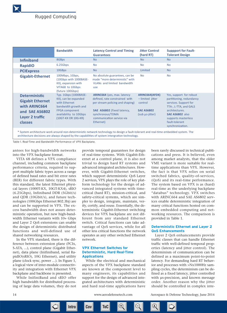
been rarely discussed in technical publi-cations and press. It is believed, evenamong market analysts, that the olderVME variant is more suitable for real-time applications than VPX. However,the fact is that VPX relies on serialswitched fabrics, quality-of-services,(QoS) and its real-time performance.The system based on VPX is as (hard)real-time as the underlying backplane“databus” technology. VPX switcheswith ARINC664 and SAE AS6802 serv-ices enable deterministic integration ofmany critical functions hosted on com-mon embedded computing and net-working resources. The comparison isprovided in Table 1.
Deterministic Ethernet and Layer 2QoS Enhancements
Layer 2 QoS enhancements providetraffic classes that can handle Ethernettraffic with well-defined temporal prop-erties (latency and jitter control). Thedeterminism of communication can bedefined as a maximum point-to-pointlatency. For demanding hard RT behav-ior and processes with >Nx1000Hz sam-pling cycles, the determinism can be de-fined as a fixed latency, jitter controlledwith μs-precision, and known messageorder. Another reason why the jittershould be controlled in complex inte-
Table 1. Real-Time and Bandwidth Performance of VPX Backplane.
Bandwidth Latency Control and Timing Guarantees
Ji�er Control(hard RT)
Suppport for Fault-Tolerant Design
Infiniband 8GBps No No No
RapidIO 6.25Gbps No No No
PCIExpress 10GBps No Limited No
Gigabit-Ethernet 100Mbps, 1Gbps, (10Gbps w ith 1 000BASE-KX), expansion with VITA68 to 10Gbps (future 100Gbps)
No a bsolute guarantees, can be made “more determinis�c” with VLANs and limited bandwidth use
No No
Determinis�c Gigabit Ethernet with ARINC664 and SAE AS6802 Layer 2 traffic classes
Typ. 1 Gbps ( 1 000BASE-KX), can be expande dwith Ethernet bandwidth growth and FPGA component availability to 10Gbps
ARINC664 ( y es, max. latency defined, rate constrained with _per stream policing and shaping)
SAE AS680 2 ( f ixed latency, synchronous/TDMA
Ethernet)
– limited ji�ercontrol
SAE AS680 2 (sub μs-ji�er)
Yes, support for r o bust par��oning, redundancy services. Support for TTA-, L-TTA, and GALS architectures. SAE AS680 2 also supports masterless fault-tolerant synchroniza�on.
* System architecture work around non-determinis�c network technology to design a fault-tolerant and real-�me embedded system. Thearchitecture decisions are always shaped by the capabili�es of system intergra�on technology.
ARINC664(AFDX)
(10GT-KX OR 10G-KR) communica�on service via
Cov ToC + – ➭
➮
AIntro

267.733.0200 x 256 [email protected]
At Pulse, our advanced technologies
aren’t only designed to make your
components thinner, stronger, lighter (or
whatever else you may need them to be).
They’re designed for quicker customization
—which gets you in market faster.
Because we know that being #1 is the
most valuable feature we could ever add.
when the right tools are available solutions come faster.
Free Info at http://info.hotims.com/49746-788
Cov ToC + – ➭
➮
AIntro

16 www.aerodefensetech.com Aerospace & Defense Technology, June 2014
Rugged Computing
grated systems is the embedded virtual-ization.
In a distributed real-time computerwith hosted hard RT functions, alongwith less critical functions for diagnosis,health management, and bulk datatransfers (e.g. recording, A/V), the ac-cess to all resources shall be predefinedin order to protect the performance forcritical functions. The availability offault-tolerant system time can simplifythe virtualization.
ARINC664 is an Ethernet traffic classthat provides defined maximum laten-cies for any periodic unicast/multicastdata stream in the system. This is ac-complished by per-stream traffic shap-ing and policing. The technology isused in integrated modular architec-tures for commercial aircraft and mili-tary transporters, such as the Boeing787, Airbus A380, Airbus A350, AirbusA400M, and many others. All new air-craft use AFDX (ARINC664) networks toreduce SWaP.
SAE AS6802 is an Ethernet traffic classthat provides fixed latencies for any pe-riodic unicast/multicast data stream inthe system, unaffected by other less crit-ical traffic load. This service also pro-vides a fault-tolerant distributed time-base used by different computing
modules in the network,and/or Ethernet devicesfor scheduled forwardingof data.
With SAE AS6802, Ether-net gains strictly determin-istic synchronous commu-nication capability and canemulate circuit-switchingcommunication in packet-switched Ethernet net-works. Figure 2 shows theposition of this service inthe OSI layer model withrelation to other Ethernetlayers and applications.SAE AS6802 services do notdepend on bandwidth ordistance — they can oper-ate at 0.1 to 10 Gbit/s orhigher and can be used inlarge networks. Togetherwith other QoS enhance-ments, Ethernet fully sup-ports synchronous and
asynchronous communication.With SAE AS6802, system functions
can be integrated on a common sharedinfrastructure and scheduled for all crit-ical functions. All other bandwidth canbe used for less critical applications.
Both ARINC664 and SAE AS6802services do not modify operation of ex-isting Ethernet services and are compli-ant with all standard Ethernet physicallayers for backbone and backplane net-works, including those described inVPX (VITA 46) and VITA 48. They arealso compliant with higher OSI Layers3-6.
Ethernet — As Deterministic as MIL-1553
With SAE AS6802 services, Ethernetnetworks can gain deterministic per-formance comparable to TDMA com-munication networks (e.g. MIL-1553 insynchronous communication mode, orTime-Triggered Protocol (TTP) – SAEAS6003), but at much higher communi-cation speed, without bus controllerand in complex switched architectures.It enables strictly deterministic commu-nication, fixed latency, sub-μs-jitter,and predictable message order in redun-dant multi-hop networks. Layer 2 Qual-ity of Service (QoS) enhancements,
standardized as Time-Triggered Ethernet(SAE AS6802), guarantee deterministiccomputing and networking perform-ance for advanced integrated systems.MIL-1553 operation can be emulatedover an Ethernet network that imple-ments SAE AS6802.
SAE AS6802 “Time-Triggered Ether-net” is used for human-rated spaceflight (NASA Orion), and evaluated fordifferent aircraft and rotorcraft systems.It is used for the design of systems thatutilize unified networking and supportintegration of hard real-time, real-time,and soft-time functions.
Advanced Integrated ArchitecturesDifferent variants of generic open ar-
chitectures can be implemented byusing VPX-based Ethernet backplaneand backbone networks, assuming theyprovide absolute temporal guaranteesand determinism for different criticalfunctions (Figure 3).
Control-plane applications in VPXtypically use single- or dual-star (redun-dant) topology with switched GigabitEthernet, which are also supported byVPX switches with SAE AS6802 QoS(TTEthernet switch). Depending on theapplication, TTEthernet switches can beused for control plane, data plane, andsome utility plane applications (syn-chronization) in VPX-based systems.This means all functions and modulesconnected to backplane and backbonenetworks operate as if they are con-nected directly to a large, fault-tolerantEthernet backbone. By allowing robustTDMA partitioning of networking re-sources, the system designer can deter-mine the level of integration/interac-tion or isolation among differentfunctions. This enables the design of in-novative architectures and distributedplatforms that can host many distrib-uted functions using shared comput-ing/networking resources for advancedintegrated system architectures.
In deterministic Gigabit-Ethernet net-works, it is possible to emulate reflectivememory by using a periodic global dataexchange with applications that aresynchronized to the global timebasegenerated at the network level by SAEAS6802 services. From the logical per-spective, different distributed functions
Figure 2. Gigabit-Ethernet switches with different Ethernet trafficclasses (QoS Layer 2 services).
Cov ToC + – ➭
➮
AIntro

BuildingBright IdeasAt Proto Labs, we accelerate innovation byturning brilliant concepts into real parts in days.
Proto Labs serves as a catalyst for product designers and engineers when real, functioning prototype parts are needed fast. Just upload a 3D CAD model for an interactive quote within hours. When ready, our Firstcut CNC-machining and Protomold injection-molding services can produce up to 10,000+ metal and plastic parts in as quick as one day. That means you can fail fast, iterate faster (and more often), and confi dently launch your product to market before competitors.
© 2014 Proto Labs, Inc. | protolabs.com | 877.479.3680Major Credit Cards Accepted | ISO 9001:2008 Certifi ed | ITAR Registered
Injection Molding Part Design for DummiesRequest your free book at protolabs.com/partsEnter code DB14B2
Free Info at http://info.hotims.com/49746-789
Cov ToC + – ➭
➮
AIntro

18 www.aerodefensetech.com Aerospace & Defense Technology, June 2014
Rugged Computing
gain a private, congestion-free sharedmemory. By using this approach, wecan scale the level of functional integra-tion without influencing other existingfunctions in the system. Also, distrib-uted applications do not need to knowabout underlying architecture or topol-ogy.
Therefore, sensor fusion and distributedpayload processing can be executedwithout fear of unintended interactionswith other system functions. Voting ondata from synchronous sources simpli-fies redundancy management and ap-plication software design. Obsolescencemanagement, modernization, and up-grades with new DSP processors and ap-plications are simplified, as the behaviorof already integrated functions will notchange and cause new system integra-tion or timing issues. Critical, hard real-time functions will not be influenced byother less critical distributed functions.Sensor front-end data can be streamedto platform systems or common corecomputing systems, with exact latencyand no jitter, independent of networkload. This also means that processingfunctions do not require spatial proxim-ity to a specific sensor, and can beplaced anywhere in the system. Thisalso simplifies reconfiguration, up-grades, and incremental modernization.
SummaryVPX modules and VPX-based Ether-
net switches like those shown in Figure4, which implement SAE AS6802 andARINC664 and support Gigabit (orhigher) bandwidth, support the designof open generic architectures in whichthe operation and interaction of all crit-ical functions can be defined at designtime, and new functions can be inte-grated with minimal impact on existingones. This significantly reduces costsand effort in all phases of system lifecy-cle, and allows integration of robusthard RT functions in integrated embed-ded systems hosting safety-, time-, andmission-critical functions. Here-with, the design of inte-grated modular ar-chi tectures,which
fol low key objectives of MOSA (ModularOpen System Acquisition) and IMA DO-297 (Integrated Modular Architectures –Design Guidance and CertificationConsideration), can be applied in com-plex Ethernet and VPX-based embeddedsystems.
This article was written by Mirko Jakovl-jevic, Senior Marketing Manager, and PerryRucker, Director of Sales, TTTech NorthAmerica Inc. (Andover, MA). For more in-formation, visit http://info.hotims.com/49746-500.
Figure 3. Advanced Integrated Architectures with deterministic Gigabit-Ethernet VPX switches.
Figure 4. DeterministicGigabit-Ethernet Switch for
VPX by TTTech.
Cov ToC + – ➭
➮
AIntro

S P O N S O R E D B Y
C A T E G O R Y
S P O N S O R
P R I Z E
S P O N S O R S
He Created the Future.
Now it’s Your Turn.THE
DESIGN CONTEST 2014
Aquaback Technologies is ramping up production of a low-cost appliance that perfectly purifies water by
energy-efficient vapor compression evaporation and condensation, the same recycling process used by the
Earth. Entering the Create the Future Contest leveraged Aquaback’s reputation with regulators, industry,
and individuals wanting to take control of their own water quality and clean water supply.
“Winning the Sustainable Technologies Category in the Create the Future Design Contest validated
Aquaback’s ability to reliably produce safe, clean water for drinking, cooking, and cleaning,” says Bill
Zebuhr, Co-CEO and CTO. “This enabled the Aquaback team to attract advance customer orders.”
Bill Zebuhr, Co-CEO
and CTO of Aquaback
Technologies. Sustainable
Technologies Category
Winner of the 2012
Create the Future Design
Contest.
www.createthefuturecontest.comTo enter, get details at
Aquaback Water Purification Systemswill begin production in the fall of 2014.
LAST CHANCE TO ENTER!Entry deadline: July 1, 2014
Free Info at http://info.hotims.com/49746-790
Cov ToC + – ➭
➮
AIntro

20 www.aerodefensetech.com Aerospace & Defense Technology, June 2014
Testing and Simulation
Comparing Blade-ElementMomentum Modeling to 3-D CFDMany small unmanned aerial vehicles (SUAVs) are driven by small-scale fixed-blade propellers, and theflow produced by the propeller can have a significant impact on the aerodynamics of the SUAV itself.
Small unmanned aerial vehicles(SUAVs) are becoming increas-ingly popular for surveillanceand numerous other applica-
tions. These SUAVs come in various sizes,and the smallest are referred to as microaerial vehicles (MAVs). For purposeshere, SUAV will be used to refer to allUAVs that are portable by a man.
SUAVs commonly use small-scalefixed-blade propellers for propulsion.Fixed-blade propellers means the bladeis rigidly fixed to the hub so that theblade pitch cannot be changed for vari-ous flight conditions. Propellersmounted in a tractor configurationoften have significant effects on SUAVaerodynamics. Therefore, to performComputational Fluid Dynamics (CFD)simulations of a SUAV-propeller system,the SUAV and the propeller must oftenbe simulated in a coupled fashion as theSUAV-propeller interaction is strong.
In the design and analysis of a SUAV,hundreds of SUAV-propeller coupledCFD simulations are needed. Performinghigh-fidelity, time-dependent 3-DReynolds-averaged Navier-Stokes (RANS)CFD simulations in which the propelleris rotated relative to the aircraft is veryexpensive computationally. For com-pactness, this method will be referred tohere as the high-fidelity blade model(HFBM). HFBM is an unsteady problem,therefore steady-state convergence accel-eration techniques cannot be used.
In addition, the fine grid needed to re-solve the detailed flow around the pro-peller blades makes the overall grid sizeextremely large. HFBM is the most accu-rate and high-resolution method of pro-peller modeling as all the 3-D, compress-ibility, rotational, transitional, andturbulence effects are modeled. However,the high computational cost of HFBMmakes it infeasible when numerous sim-ulations are needed, as is the case formany SUAV-propeller problems.
For computational efficiency, steady-state models approximate the time-aver-age flow produced by a propeller. Thesemodels embed momentum source termsinto the propeller region of a mesh to in-duce thrust and swirl into the flow field.Many of these momentum source mod-els are based on blade-element momen-tum theory (BEMT). BEMT determinesthe thrust and swirl from 2-D airfoil data.However, flow around small-scale pro-pellers can be very complex and highly3-D in nature, making it difficult forBEMT to accurately predict the propellerperformance in many instances.
For this study, researchers from Mis-sissippi State University comparedHFBM simulations to a BEMT model fortwo small-scale propellers to determinethe validity of using BEMT to model
small-scale propellers in a wide range offlight conditions.
High-Fidelity Blade Modeling HFBM simulations were conducted
with an in-house code at MSU calledCHEM. CHEM is a second-order accurate,cell-centered finite volume CFD code andhas been validated and applied to a widerange of problems. All HFBM simulationswere compressible, viscous, and assumedto be turbulent using Menter's shearstress transport (SST) turbulence model.While the Reynold’s number was low(<150,000), the SST turbulence modelwas used to achieve settled solutionssince unsteady vortex shedding occurs.
The HFBM simulations consisted ofmodeling an isolated propeller with noother bodies in the flow. The flow wasuniform and at 0° angle of attack relativeto the axis of rotation. Therefore, the flowat each blade was periodic and steady-state when viewed in the fixed-blade ref-erence frame. Only one blade was mod-eled, as the problem was periodic andthus periodic boundary conditions wereapplied to the axisymmetric planes.
AFLR (advancing–front, local–recon-nection) was used to generate the un-structured mesh. The entire mesh was ro-tated for unsteady simulations in whichone time-step corresponded to one de-gree of rotation. A time-step study wasconducted to ensure the time-step usedwas small enough to accurately resolvethe flow field. The grid was rotated forfive revolutions so the force on the bladewas settled without any start-up effects.
Computational efficiency could begained by simulating the propeller as asteady-state computation in the fixedblade reference frame. However, un-steady computations were conducted forpurposes of similarity to other CFD sim-ulations in related research.
The surface of the blade was dividedinto sections so the CHEM code could
To analyze the significance of 3-D effects on smallscale propellers, two propellers were simulatedusing BEMT and HFBM. Both propellers were twobladed, had a 10-in diameter, and were made using aNACA 4412 airfoil for the blade sections. Propeller 1(top) had a high aspect ratio of ~11 and no chord vari-ation or sweep along the blade. Propeller 2 (bottom)had an aspect ratio of ~5 based on the largest chordin the blade, and it had significant chord variationlike many small-scale propellers.
Periodic domain for the HFBM simulations.
Cov ToC + – ➭
➮
AIntro

output the total force (viscous and invis-cid) vector on each blade element. Nowall functions were used, and so the gridnear the viscous surface was refined toensure the boundary layer is capturedwith a high resolution.
The top and bottom surfaces of theblade were each covered with 66 points.A far field size study was conducted toensure the outer boundary of the com-putation domain was far enough away tonot affect the propeller aerodynamics.The outer boundary was 12 blade lengthsaway from the propeller blade. The totalgrid size was 5.6 million elements, andthe HFBM simulations were run in a fewhours on the Talon super computer atthe High Performance Computing Col-laboratory of MSU.
Blade-Element Momentum Theory To implement BEMT, a set of lift and
drag curves were needed for the NACA4412. The lift and drag on a 2-D airfoilare functions of angle of attack, Reynoldsnumber, and Mach number. The tipMach number for the propeller cases wassmall, <0.32, so compressibility effectswere assumed to be negligible.
These low Mach numbers are typicalfor small-scale propellers due to the lowflight speed and small propeller diameter.Some SUAVs have very high propeller ro-tation speeds causing the flow at the bladetip to be compressible despite the smallpropeller diameter. In these cases, Machnumber can be considered in BEMT. How-ever, for the test cases here it was unneces-sary to include compressibility effects asthe tip Mach number was low.
To conduct the CFD simulations tomake the lift and drag curves, the Machnumber was held constant at a moderatevalue of 0.15. Airfoil simulations coveredthe range of the Reynolds number expe-rienced by each blade element (10,000-
150,000). This range of Reynolds varia-tion can have a significant effect on theairfoil's lift and drag, especially when aturbulence model is used.
A database of lift and drag data for theNACA 4412 airfoil was developed thatcovered the range of angle of attack and
Reynolds number experienced by theblade elements for the propeller cases.For a direct comparison of BEMT to theHFBM simulations, similarity was main-tained as much as possible between the2-D airfoil CFD simulations and theHFBM simulations.
Aerospace & Defense Technology, June 2014 21Free Info at http://info.hotims.com/49746-791
Testing and Simulation
A cross section of the 3-D HFBM mesh around theblade at r/R = 0.4.
There are many CMMs. One software makes them more powerful.Whether you have an existing CMM device or about to purchase one, Verisurf-X is the only software you need. With its 3D CAD-based architecture, fl exible reporting options, and ease of use, Verisurf-X will reduce training time and increase productivity, right out of the box. No matter what you are making or measuring, Verisurf-X provides the power to drive your devices, reduce cost, improve quality, and streamline data management – all while maintaining CAD-based digital workfl ow.
Learn more about the power of Verisurf-X by visiting our Website,
or call for an onsite demo.
Cov ToC + – ➭
➮
AIntro

22 Aerospace & Defense Technology, June 2014Free Info at http://info.hotims.com/49746-792
Testing and Simulation
The CHEM code was also used to per-form 2-D airfoils simulations with the SSTturbulence model. For grid similarity, thesame number and distribution of pointsused on a blade cross section for theHFBM grid was also used on the 2-D air-foil grid that was also made with AFLR.Therefore, the 2-D airfoil grid looked sim-ilar to the cross section of the 3-D gridgenerated for the HFBM mesh. In addi-tion, the boundary layer was captured toa similar resolution as in the HFBM.
The BEMT model was programmed inMathematica and only took a few min-utes to run on a personal computer. Mo-mentum theory was chosen as it is one ofthe most commonly used methods to cal-culate the induced velocities for blade-ele-ment theory (BET). BEMT is well docu-mented in literature and is easilyimplemented with an iterative solutionprocedure. Prandtl's tip and hub loss cor-rection factors were incorporated with themodel, and no stall-delay model was used.
Analyzing Results For propellers with high aspect ratio
blades operating in conditions with littleseparation, BEMT was able to closely pre-dict the distribution of thrust along theblade, as the 3-D effects were small. How-ever, as the 3-D effects increased by way ofblade geometry or operating conditions,BEMT lost accuracy and thus applicability.
Correction models can be developedfor and applied to specific tip geometriesand propellers to achieve better agree-ment. However, these correction modelsfor tip loss, hub loss, stall-delay, and rota-tional effects have difficulty in beinggeneralized for a wide range of propellergeometries and operating conditions.
Despite these limitations in applicabil-ity, BET models are widely used whenmodeling propellers in CFD as they canbe implemented as a computationally ef-ficient steady-state model.
HFBM provided a time-accurate, high-resolution solution for the propeller that
The spanwise thrust distribution (or thrust profile)for propeller 1 in cruise conditions. In this case, theBEMT model agrees very well with HFBM, with a5.4% error. Most of the error is at r/R = 0.9 due tothe tip loss effect.
The thrust profile for propeller 1 in low speed con-ditions. BEMT, in this case, has considerable differ-ences from HFBM with an error of 14.7%. Moreerror is seen in the inboard and tip region of theblade due to separation.
Cov ToC + – ➭
➮
AIntro

Aerospace & Defense Technology, June 2014 www.aerodefensetech.com 23
Testing and Simulation
considered all 3-D effects. However,HFBM comes at a very high computa-tional cost.
A fine resolution grid is needed to re-solve the flow around the propeller. Inaddition, the problem is time-dependentand restricted to a small time-step to re-solve the fast propeller rotation. Thishigh computational cost of HFBM limitsits use for many applications despite thehigh accuracy.
It is worth noting that the 3-D effectsof separation and low aspect ratio thatcause inaccuracies with BET are notspecifically unique to small-scale pro-pellers. Full-scale aircraft propellers, windturbines, and other propeller or fan ap-plications may also have strong 3-D ef-fects, making BET insufficient. However,small-scale propellers on SUAVs are par-ticularly prone to strong 3-D effects fromblade geometry, non-variable pitchblades, and operation in a wide range offlight conditions.
The results presented here are intendedto show situations in which the 2-D flowassumption of BET breaks down. There-fore, full 3-D CFD was compared directlyto BEMT, whose aerodynamic databasewas developed as similar as possible tothe HFBM simulations. This comparisonallowed a detailed analysis of the flowfield to examine why BEMT loses accu-racy in certain flight conditions.
The physical accuracy of HFBM to ex-perimental data is not guaranteed de-spite its consideration of 3-D effects.However, it is beyond the scope here tocompare HFBM to experimental data, asHFBM is widely used and accepted in de-tailed propeller analysis. Other work hascompared experimental results, ratherthan HFBM, to BEMT calculations. In
such a case, global thrust quantities werecompared rather than thrust distribu-tions along the blade, and similar resultswere found showing how BEMT is inac-curate in cases with separated flow.
Propeller-Aircraft Coupling The main objective of propeller mod-
eling in this SUAV context was propeller-aircraft coupled CFD simulation. Often,the desired information from these cou-pled CFD simulations are the time-aver-aged loads on the aircraft that requirenumerous simulations. To save computa-tion time, a steady-state, computation-ally efficient momentum source methodis desired.
Currently, BET is the most accurate andcommon method on which to base a mo-mentum source model in CFD. When im-plemented in 3-D CFD, BET does not nec-essarily need another model to calculatethe induced velocities, as the 3-D CFD so-lution calculates the induction by satisfy-ing the Navier-Stokes equations over theflow domain. Momentum source termmodels based on BET that are imple-mented into 3-D CFD are well docu-mented and are currently the most popu-lar way to implement a time-averagedpropeller model.
For such models, the magnitude ofthe source terms are based on 2-D air-foil characteristics and are calculatedfrom the inputs of angle of attack,Reynolds number, and Mach numbertaken locally in the flow field. There-fore, the source terms are locally cou-pled to the flow field and adapt as thesolution progresses. Due to the local in-puts, different flight conditions and in-terference effects from aircraft cou-
plings are considered in the calculationof the source terms.
Nonetheless, the 2-D flow assumptionof BET fails to account for many of thecomplex 3-D flow characteristics thatcan significantly affect propeller per-formance, limiting its accuracy andrange of applicability. Fundamentally,the BET assumes the flow over each ele-ment to be 2-D in nature.
However, the work here has shownthat propeller aerodynamics can behighly 3-D and thus not accurately pre-dicted by 2-D airfoil data. To obtain accu-rate loads on an aircraft that is affectedby the propeller flow, the magnitude ofmomentum sources must be correct.
So while the momentum source termimplementations of BET are locally adap-tive to different flow conditions and air-craft couplings, the magnitude of thesource terms can have considerable er-rors when 3-D effects are significant onthe propeller, as is often the case forsmall-scale fixed-blade propellers.
This article is based on SAE Internationaltechnical paper 2013-01-2270 by JosephCarroll and David Marcum, MississippiState University.
Velocity vectors at cross section at r/R = 0.3 for pro-peller 2 in low speed conditions. Propeller 2 mainlydiffers from propeller 1 in that it has chord variationand sweep to the blade like many small-scale pro-pellers. The velocity vectors in the first few cells offthe wall point outward in the radial direction due tothe centrifugal force from the rotation. However,the flow is not separated as the velocity vectors donot point back towards the leading edge.
The thrust profile comparisons between BEMT andHFBM for propeller 2. BEMT has an 11.9% error inthrust for this case. This error is not attributed toseparation, and must be attributed to the lowaspect ratio, chord variation and sweep of the pro-peller blade.
The velocity vectors of the HFBM simulations atblade cross sections of r/R = 0.9 for propeller 1 at lowspeed are shown to visualize separation, which is pin-pointed by an oval. The separation occurs toward thetrailing edge on the upper surface of the airfoil.
Velocity vectors at cross section at r/R = 0.3 forpropeller 1 low speed conditions case showing sep-aration. When separation occurs, the flowbecomes highly 3D in nature with large spanwisecomponents and BET loses accuracy.
Cov ToC + – ➭
➮
AIntro

24 www.aerodefensetech.com Aerospace & Defense Technology, June 2014
Europe's Aerospace IndustryLooking ConfidentApart from Airbus’s highly visible presence in defense and commercial aircraft, Europe also hassuccessful capabilities in helicopters, business jets, and aero engines, and in all these areas theirglobal market share is growing.
by Richard Gardner
Talk of further consolidationwithin Europe’s dynamic aero-space sector has been on thelips of industry watchers for
several years, but although the majorEuropean-based global players have notprogressed toward further mergers, thecontinent’s biggest aerospace company,the former EADS, has achieved a verysignificant business restructuring,sweeping all its diverse companies intoone giant, three-division entity, andadopting the new corporate identity ofthe Airbus Group.
At one stage it looked as if a proposedmerger between EADS and BAE Systemsmight create the world’s largest com-bined aerospace and defense company,but a German political veto put an endto this plan, largely because of sensitivityover the defense aspects of such a deal.
BAE Systems has a key role in theU.K.’s nuclear weapons program, andwhile Germans are enthusiastic on com-mercial aviation, the subject of nucleardefense is one that its politicians andpublic are happy to leave to the British,
French, and U.S. The general reluctanceof many NATO nations to maintaintheir defense budgets has caused a seri-ous knock-on effect rippling throughmuch of the European defense sector.
Legacy air defense programs, such asthe Dassault Rafale, SAAB Gripen, andEurofighter Typhoon, are today still pro-
viding plenty of production work, andupgraded versions are on the way, butbeyond 2020 these programs are de-pendent on winning more export ordersto avoid serious implications for existingassembly plants.
There are today relatively few new Eu-ropean military air programs, but one of
The Airbus Helicopter Tiger attack helicopter.
The French Rafale fighter represents the best in today's European military aviation portfolio with a pow-erful and flexible multi-role supersonic performance. (Dassault)
Cov ToC + – ➭
➮
AIntro

Aerospace & Defense Technology, June 2014 25Free Info at http://info.hotims.com/49746-793
European Aerospace Programs
the largest, the Airbus A400Mtransport, should generate newexport sales and will extend pro-duction out well into the nextdecade, but other market sectors,such as jet trainers and surveil-lance aircraft, are proving veryslow to mature into large-scaleproduction.
The need to take a long-termstrategic view on aerospace is rec-ognized at the political and tech-nical European Union level. In-vestment in highly innovativetechnologies and manufacturingmethods is underway in an effortto retain a broad-based leadershiprole and to stay competitive with up-coming developments and productioncapacity in the BRIC countries (Brazil,Russia, India, and China). Heavy invest-ment by European companies in over-seas assembly plants has seen Airbus set-ting up factories in the U.S. (civil aircraft
and helicopters) and Brazil (helicopters);Rolls-Royce expanding R&D facilities aswell as production in the U.S. and Singa-pore; BAE Systems becoming well estab-lished in the U.S. and Australia; andItaly’s Finmeccanica Group expandingin the U.S.
A New Airbus Is Born The restructuring of EADS into
the new Airbus Group is far morethan just a commercial re-brandingoperation. After decades of transat-lantic criticism that Airbus is toopolitical, and regarded by Europeanleaders as a high-profile status sym-bol that must be subsidized—aclaim always denied in Europe—the changes within the new Airbusfinally create the accountable andtransparent company structurethat brings it into line with otherglobal corporations.
Of course, financial assistancewill still be willingly given by Eu-
ropean governments to help invest innew programs and longer-term researchand development, as is the case in theU.S. and elsewhere, but in businessterms Airbus is now seen as a highlyprofitable independent enterprise thathas broken free of its state controls.
Snecma's M88 engines power the Rafale, and the core of theengine has been adopted for the A400M’s turboprop engine thatwill be developed in a new open rotor prototype program.
Verify your control system
design! =)
For more information and free application notes, go to www.omicron-lab.com
How stable is your power supply?Determine the stability of your control loop using the Vector Network Analyzer Bode 100 in combination with the Wideband Injection Transformer B-WIT 100.
Loop gainPlant transfer functionPhase and gain margin
Easily measure from 1 Hz to 40 MHz:
Cov ToC + – ➭
➮
AIntro

26 www.aerodefensetech.com Aerospace & Defense Technology, June 2014
European Aerospace Programs
In re-paying government loans throughthe generation of profits from its civil air-liners, it has produced an extremely gooddeal for European taxpayers. For example,the best-selling A320 family was originally
forecast to break even if 200 were sold.Today, the sales total for these single-aislejetliners is a staggering 10,200, with abacklog of 4200 aircraft yet to be deliv-ered. European governments that have
supported Airbus financially collect a roy-alty on every one sold, so while it will besome time before they see a return fromsales of the giant but slow-selling A380,the A320 has become a commercial suc-cess on a grand scale.
Because the delivery timescales havenow become so extended, Airbus has re-cently announced that it is raising theA320 production rate to 46 a month in2016. Final assembly plants in Germany,France, and China will be joined by anew Airbus factory in Mobile, AL, nextyear. Just six years ago production wascut because of the financial crisis andfalling demand, but since 2010 the de-mand has returned and monthly flowhas gradually increased from 36 to thecurrent rate of 42. By 2018 it could reacha monthly total output of 50 aircraft.
Since the decision to go ahead withthe A320neo, with a potential 15% re-duction in operating costs, sales havesurged, and this has created a real chal-lenge, as well as welcome news, foreveryone across the global supplychain. Airbus Group CEO Tom Endershas played a key role in steering thenew Airbus through a complex, multi-national transition, and he has insistedon developing a close partnership withhis supply chain in what he describes asan “extended enterprise.” He firmly be-lieves that taking the suppliers into acloser, rather than confrontational, rela-tionship is an important strategy if pro-duction costs are to be kept down.
The latest civil Airbus, the A350 fam-ily, is making rapid progress toward cer-tification and first deliveries by the endof this year. Four aircraft are now in thetest flight phase, with over 1100 hoursachieved by the first two. One of the de-velopment aircraft is being fully fittedout with passenger seats and cabin sys-tems and will soon embark on long en-durance test and evaluation flying.
The A350 is being developed into afamily of wide-body transports, seatingfrom 276 in the A350-800 to 369 in theA350-1000, and with a non-stop rangeof up to 8250 mi. Nearly all A350 cus-tomers have selected the -900 and -1000versions, and the -800 may be dropped.All variants are powered by two Rolls-Royce Trent XWB engines. The combi-nation of advanced aerodynamics, aThe new A350 is due to enter service before the end of this year, and full production is ramping up in a new factory.
The Eurofighter Typhoon is evolving from an agile air defense fighter into a genuine multi-rolefighter/bomber/reconnaissance aircraft.
A Gulf Air Airbus A320. This family of twin jetliners has achieved sales of over 10,200 aircraft and is beingproduced at a rate of more than 40 each month.
Cov ToC + – ➭
➮
AIntro

wide cross-section fuselage with over50% made from composite materials,and lean burn engines will offer a 25%reduction in seat mile costs comparedto equivalent size current jets.
Further cost reductions are expectedfrom reduced training requirements dueto a common flight deck design and fly-ing qualities shared with all the otherAirbus designs, the A320, A330, andA380. The latter remains the largestcommercial airliner in production, witha passenger capacity from around 450up to 700 in a high-density configura-tion. The A330 is still in great demandand is being offered with improved pay-load, and a version is optimized forhigh-density regional routes, aimed atChina and the Asian market.
A military tanker/transport version ofthe A330 is proving to be a popular choicefor many air forces seeking to update theirair refueling and military transport fleets.This aircraft is large enough to be able tocarry up to 265 troops and their equip-ment in the cabin, while at the same timeit carries enough fuel to replenish receiveraircraft from two underwing refuelingpods. A USAF-style refueling boom canalso be carried on the rear fuselage center-line, or a third hose and drogue unit.
Business Jets This sector has been well served by
European designs over the years but isnow one of the most hotly contestedsectors in the whole commercial aero-space market, with major competitorsincluding Gulfstream and Cessna in theU.S., Bombardier in Canada, and Em-braer in Brazil.
Europe’s leading supplier in this mar-ket is Dassault Aviation, with its familyof twin and tri-jet Falcon aircraft. Allfeature very high-end specifications, interms of performance, advanced flightsystems, and passenger appeal, and thisreflects the company’s commitment toheavy investment in R&D and a strongtechnological heritage inherited fromadvanced combat jets.
The latest Falcon jet, the 5X, is all-new, and will emerge to join the Das-sault bizjet family in 2015. It will featurea similar fly-by-wire flight control sys-tem to the tri-jet Falcon 7X but will havea larger cabin and “the most advanced
flight deck in civil aviation,” with nu-merous head-up and head-down dis-plays, additional integrated enhancedvision sensors, and features to permitsafe operation at night and in poor visi-bility when using runways in restrictedlocations, such as in mountain valleys.
Dassault has continued to upgrade allits family of jets to keep them highlycompetitive and has worked closely withother aerospace companies in the paston designs for a supersonic business jet,but the lack of a fuel-efficient and quietengine that can cruise at a supersonic
Aerospace & Defense Technology, June 2014 27Free Info at http://info.hotims.com/49746-794
European Aerospace Programs
Cov ToC + – ➭
➮
AIntro

28 www.aerodefensetech.com Aerospace & Defense Technology, June 2014
European Aerospace Programs
speed over extended ranges has so far de-feated all attempts at bringing a viablebizjet-size SST product to market.
European Helicopters The reorganization of EADS saw the
strong Eurocopter brand morphed intoAirbus Helicopters. Apart from the namechange, this rotary wing business hascontinued as before, with a world-leadingmarket share in military and civilian mar-kets. It has not developed any heavy-liftmilitary products to challenge the BoeingCH-47 Chinook, but in all other size cat-egories of helicopter the company hasmodels that offer the latest standards inavionics and flight safety.
The NH-90 is the latest military heli-copter and is in large-scale productionfor European and export customers. It is
the most important of the new pro-grams. Slightly larger than the SikorskyS-60/70 Blackhawk and Seahawk, it has afuselage that can accommodate a so-phisticated anti-submarine/anti-surfacenaval equipment fit, and there is also autility army version with a large rearcabin ramp.
Other medium helicopters in the SuperPuma family are popular worldwide forsearch and rescue, combat SAR, specialmissions, and oil and exploration supportoperations. Smaller helicopters in thefamily provide paramedic support and po-lice support capabilities, as well as general-purpose civil and military utility roles.
The main European rotary wing com-petitor to Airbus Helicopter is Agusta -Westland, which has a very wide rang-ing portfolio from the AW101 Merlin
and Lynx Wildcat military helicoptersto a whole family of new-generationsmall and medium helicopters, includ-ing the AW139, AW169, and AW189.This latest family has high levels ofcommonality between the differenttypes and also uses common tools andground support equipment. A reduc-tion of up to 40% in training time re-sults. This family is aimed initially atoil-rig support, light transport, SAR,and coastal surveillance, but more pro-tected, armed, military transport vari-ants are emerging, offering high speedas well as a low profile for added surviv-ability over the battlefield.
Powered Up Europe’s aero engine manufacturers
include Snecma in France, MTU in Ger-many, and Rolls-Royce in the U.K. Allare truly international with programsstretching to partners across the globe.MTU is closely involved in partnershipswith both Pratt & Whitney and RollsRoyce on civil and military engines.
Rolls-Royce has around 50% share ofthe world’s big fan market with its Trentseries, which covers thrust ranges fromover 50,000 lb up to 110,000 lb. Trentspower all the largest current widebodyjets apart from the Boeing 777-300ER,and the latest Trent XWB is due to enterservice later this year on the A350.
Development work is underway onenhanced Trent derivatives that mighthave application on a revised A330 andpossibly the A380. Snecma, through itsCFM partnership with GE, has well overhalf the engine market on the A320 fam-ily and is sole powerplant on the Boeing737 classic. The CFM Leap engine is des-tined for the 737 MAX and A320neo.
Although it has lost out powering thelatest 737s and A320s, Rolls-Royce is de-termined to re-join this market at sometime in the future, possibly via a newBoeing airliner sized between the 737MAX and the 787.
In the meantime, CFM is moving for-ward with development of a prototypenew-generation open rotor engine. Ifsuccessful, a suitable powerplant can bematured in advance of the follow-on150 seat civil programs that will eventu-ally replace the 737 MAX and A320neoin the late 2020s.
The U.K. aerospace industry has a major share in the F-35 program, producing rear fuselage, fin assem-blies, and the ejector seats, and providing the Rolls-Royce lift fan that gives the F-35B model its verticaltakeoff and landing capability. (MOD)
The Dassault Falcon 200S and 7X business jets.
Cov ToC + – ➭
➮
AIntro

Aerospace & Defense Technology, June 2014 www.aerodefensetech.com 29
RF & Microwave Technology
Advances and Challenges inDeveloping Radar ApplicationsSignificant advances in digital and RF/microwave technologies are leading to more diverse radarapplications as well as greater commercialization. This article discusses some of the fundamentalresearch and development challenges in both the digital and RF/millimeter-wave domains, as well ascurrent and future directions in design, system integration, and test.
Radar is used to detect and/ortrack target objects and theirattributes, such as range,speed, and other information
obtained through signals at RF and mi-crowave frequencies. The broad classesof radar systems are active and passive(Figure 1). Passive radar systems usenon-cooperative source(s) of illumina-tion, such as a target’s emitted signals,broadcast signals, or cellular communi-
cation signals, to obtain informationabout the target. Since radar perform-ance relies on the sensing capabilities ofthe receiver, significant innovationshave been made in areas such as phasedarray antennas, digital beamforming,detection algorithms, and source sepa-ration algorithms. Active radar uses co-operative sources of illumination bygenerating its own signal(s) to illumi-nate the target. Within the class of ac-
tive radar, there is monostatic radar,where the signal source is collocatedwith the receiver, and multistatic radar,where there are two or more receiver lo-cations.
Among active radar systems, thereare several common signal types. Themost basic is continuous wave (CW)radar, where a constant frequency sinu-soidal signal is transmitted. The CWsignal allows the receiver to detectphase/frequency variations (Dopplershift) from the target reflection. Unlessa special provision for absolute timemarker is used, however, range detec-tion is not possible. A modified CW sig-nal using a stepped frequency modu-lated (SFM) signal obtains a betterrange estimate by hopping over multi-ple discrete frequencies. A further mod-ification of the CW signal to linearlyramp up and down a range of frequen-cies is called linear frequency modula-tion (LFM) or frequency modulated CW(Figure 2). An LFM radar allows detec-tion of Doppler as well as range by ob-serving the frequency difference of thetime-delayed received signal from thetransmitted signal. If a stationary ob-
Figure 1. Passive radar (left) and active radar (right).
Figure 2. Example LFM waveform where a pulse ramps from high frequency to low, and back again.
Cov ToC + – ➭
➮
AIntro

30 www.aerodefensetech.com Aerospace & Defense Technology, June 2014
RF & Microwave Technology
ject is detected, a constant beat fre-quency (transmit to receive frequencydifference) is observed.
Without loss of generality, today’sactive radar system design can be bro-ken into two major components: thebaseband signal processing and theRF/microwave front end (includingthe antenna). Figure 3 shows a high-level block diagram of an active radarsystem.
Digital Signal ProcessingThanks to widely available commer-
cial processors, embedded processors,field-programmable gate arrays (FPGA),digital signal processors (DSP), and,more recently, graphics processing units(GPU), radar signal processing engineersnow have a breadth of platforms fromwhich to choose. The choice largely de-pends on the type of signal processingthat is needed and the cost of imple-mentation. General-purpose, personal-computer-type hardware may be suffi-cient for radar systems with relativelylow throughput and simple signal pro-cessing requirements. An FPGA or GPU-based processor might be needed if large
parallel processing is needed. In thiscase, however, the cost of the hardwareincreases substantially. In most plat-forms, pulse generation and receiver al-gorithms can be implemented with ap-propriate software, bringing benefitssuch as programmability and reuse ofintellectual property. At the same time,radar signal processing engineers arefaced with the challenge of incorporat-ing more and more sophisticated algo-rithms, consuming longer simulationtimes within the system and exhaustingthe available computational resources.
While each of the processing blockshas relatively simple functions, it be-comes a complex task to integrate thesealgorithms, partition them onto appro-priate platforms, coordinate and com-municate with the RF/microwave frontend, and compensate for its non-ideali-ties. Does it make sense to implementall of the processing in the FPGA at thecost of hardware, development time,and less flexibility? Does it make senseto implement all of the processing onthe CPU, perhaps at the cost of perform-ance? Or does it make sense to partitionthe algorithms for the CPU and FPGA
(and maybe DSP) such that each algo-rithm is run in some optimal way? If so,what are the throughput, latency, andsynchronization requirements betweenthese processing units? These are someof the challenges faced by radar signalprocessing engineers in developing thenext generation of radar systems.
RF/Microwave Front EndThe transmitter and receiver unit (Fig-
ure 4) plays a key role in acquiring theinformation for processing. Many radarsystems today operate at S-Band (2 to 4GHz), X-Band (8 to 12 GHz), and higher.Design choices for the transmitter up-converter and receiver downconverterdepend on many factors, such as the tar-get frequency range, available local oscil-lators, interfaces to the DAC and ADC,phase/amplitude control, and cost. Per-haps the most heavily researched areasare high power amplifier (HPA) and lownoise amplifier (LNA) design.
The HPA performs the critical func-tion of amplifying the illumination sig-nal to the highest power permittedwithout adding distortion, while havinghigh enough efficiency to maintainpower consumption within specifiedlimits. Depending on the application,transmit power levels can range frommilliwatts to kilowatts. Linearity of thepower amplifier is of great importancesince nonlinearity can cause pulsedegradation and introduce spurs that vi-olate spectral mask requirements or cor-rupt the receive signal. In recent years,field plate technology has allowed GaAsHPAs to be operated at higher voltages.Field plate technology and air-bridgesincrease the breakdown voltages of highelectron mobility transistors (HEMT).Increased power density, however, in-troduces heat dissipation issues. Fieldplate technology has been used with de-vices that already support higher volt-ages and power densities, such as gal-lium nitride (GaN) on silicon carbide(SiC) substrates. PA designers are facedwith a multitude of problems in tradingoff devices, component count, thermalmanagement, and miniaturization, allwhile satisfying the amplification andspurious emission requirements.
While LNA design is relatively ma-ture, its performance is crucial to
Figure 4. High-level block diagram of a radar front-end transmit and receive unit.
Figure 3. General radar block diagram.
Cov ToC + – ➭
➮
AIntro

Get it airborne with feature-packedhybrid switch matrices.
SIGNAL & CONTROL SOLUTIONS
Is the lack of a lightweight, high
power switch matrix keeping
your antenna/sensor system
grounded? Aeroflex Signal and
Control Solutions (ASCS) can
help.
Covering UHF through
Ka band, ASCS’s broadband
and multi-octave solutions are
available in nearly limitless I/O
configurations. They’re housed
in your choice of fully hermetic
or non-hermetic packaging,
and can be engineered
to incorporate all your
BIT, attenuation, filtering,
amplification and conversion
requirements.
With decades of hybrid chip
and wire and SMT experience,
you can count on ASCS to
achieve all your insertion loss,
gain, signal output and size
reduction goals.
Talk with an application
engineer today.
732-460-0212
www.aeroflex.com/ASCS
Free Info at http://info.hotims.com/49746-795Free Info at http://info.hotims.com/49746-795
Cov ToC + – ➭
➮
AIntro

www.aerodefensetech.com Aerospace & Defense Technology, June 2014Free Info at http://info.hotims.com/49746-796
RF & Microwave Technology
achieving front-end sensitivity andoverall radar performance goals. Linkbudget and noise figure analyses havehistorically been performed with simplehand calculations or spreadsheets; how-ever, use of a graphical tool like the NIAWR Visual System Simulator (VSS) orsimilar, greatly enhances the designer’sability to close in on the specificationand spot problem areas (Figure 5).
Integration: Putting it All TogetherThe radar system architect has the
enormous task of understanding vari-ous tradeoffs in the digital domain aswell as in the RF/microwave domain,and putting it all together. Many yearsago, radar systems might have been de-signed and integrated by a small teamof hardware engineers, but today’s radarsystems are becoming increasingly com-
Figure 6. An example of an integrated tool chain by the National Instruments AWR Visual SystemSimulator.
Figure 5. Link budget analysis using the National Instruments AWR Visual System Simulator.
www.feko.info
FEKO includes several
computational methods, each
optimised for different problem
types. Due to a long history of
hybridising different techniques,
FEKO has been at the forefront of
the efficient analysis of complex,
low and high frequency problems.
Applications:
Antenna Design, Antenna
Placement, Waveguide, RF
Components, Microstrip Circuits,
EMC, Cable Coupling, Radomes,
RCS, Bio-EM.
One Product - Multiple Solvers
Global sales and technicalsupport network:
Local distributors in Europe, North America, South America, Japan, China, South Korea,
Singapore, India, Israel, Taiwan, South Africa
UTD
Ele
ctri
cal S
ize
Complexity of Materials
PO/GO
MLFMM
MOM
FEM
OUR DOMAIN: HYBRIDISATION
MoM (since 1991)
MoM/PO (since 1992)
MoM/UTD (since 1994)
MLFMM (since 2004)
MoM/FEM (since 2005)
MoM/RL-GO (since 2007)
FEM/MLFMM (since 2010)
Cov ToC + – ➭
➮
AIntro

plex with domain experts from severalareas contributing to the developmentof one system. How can an algorithmictradeoff be adequately balanced withmicrowave circuit requirements andcost? There is clearly a greater need formixed digital and RF/microwave design,simulation, and a prototype frameworkso that the corresponding domain ex-perts can communicate with each otherto address this complex design problem.One approach is to consider a well-inte-grated tool chain that supports mi-crowave design, digital signal process-ing, hardware-in-the-loop (eitherhardware-based processing such as onFPGAs or measurements), and the corre-sponding hardware capability to sup-port rapid prototyping of designs (Fig-ure 6). Various systems softwarepackages allow multiple designers toeasily create and evaluate subsystem ar-chitectures, bringing their designs fromconcept to simulation and, ultimately,to physical implementation in a singlesystem within a single framework.
ConclusionToday’s radar systems are as complex
as they are diverse. What is common,however, is that they each contain adigital signal processing section andRF/microwave front end. In this article,we looked at a few key elements inboth of these areas with examples forpulse compression radar and discussedseveral technology challenges as well.While radar systems previously weredeveloped by a few hardware engi-neers, today’s systems often rely on thedesign contributions of multiple do-main experts. Various software toolssimplify the complexity of the designprocess and allow engineers to thinkacross the traditional boundaries.
This article was written by Dr. TakaoInoue, Senior RF Platform Engineer, andPhyllis Cosentino, Senior Product Market-ing Manager, at National Instruments inAustin, TX. For more information, visithttp://info.hotims.com/49746-541.
References
1) M. Grossi, A. Fiorello and S. Pagliai,“Advances in Radar Systems by SELEX SistemiIntegrati: Today and Towards the Future,”European Radar Conference Proceedings,September-October 2009, pp. 310-317.
2) J. Hasch, E. Topak, R. Schnabel, T. Zwick, R.Weigel and C. Waldschmidt, “Milli meter-Wave Technology for Auto motive RadarSensors in the 77 GHz Frequency Band,” IEEETransactions on Microwave Theory andTechniques, Vol. 60, No. 3, March 2012, pp.845, 860.
3) C. Li, J. Cummings, J. Lam, E. Graves and W.Wu, “Radar Remote Monitoring of Vital
Signs,” IEEE Microwave Magazine, Vol. 10,No. 1, February 2009, pp. 47-56. C. Gentner,E. Munoz, M. Khider, E. Staudinger, S. Sandand A. Dammann, “Particle Filter BasedPositioning With 3GPP-LTE in IndoorEnvironments,” IEEE/ION Position Locationand Navigation Symposium Proceedings,April 2012, pp. 301, 308
Aerospace & Defense Technology, June 2014 33Free Info at http://info.hotims.com/49746-797
RF & Microwave Technology
Cov ToC + – ➭
➮
AIntro

34 Aerospace & Defense Technology, June 2014Free Info at http://info.hotims.com/49746-798
RF & Microwave Technology
Simulation Tools Prevent Signal Interference on Spacecraft
Launching a satellite into spacerequires painstaking prepara-
tion, not only to make sure that amultitude of technologies are func-tioning, but also to ensure that crit-ical components are working to-gether in unison. One example isthe communication systems on-board satellites and the rockets usedto launch them.
A number of receivers and trans-mitters are installed into both satel-lites and rockets so that engineers onEarth can use radio signals to trackand control their every movement,and function and troubleshoot prob-lems that may arise during ascent.Once securely in orbit, satellites alsosend data back to Earth for telecom-munications and scientific research.
But having multiple pieces ofequipment sending and receiving Delcross’ EMIT interference simulation software analyzes for co-site interference between different RF systems.
SINCE 1968
[email protected] David Road, North Attleboro MA 02761-0069
Thick & Thin Film Resistor Products• Faithful scheduled deliveries under 2 weeks• Values from 0.1 Ohm to 100G Ohm• Abs. tolerance to ±0.005%, matching to ±0.0025%• TCR’s to ±2ppm/°C, tracking to ±1ppm/°C• Operating frequencies to 40GHz• High performance at cryogenic temperatures• Case sizes to 0101• Space level QPL’s, F.R.-“S”, per MIL-PRF-55342• Zero failures with over 200 million life test hours• ISO 9001:2000 certified• Full line of RoHS compliant products • 24-hour quote turnaround 44 YEARS OF EXCELLENCE
PROVEN RELIABILITY. TRUSTED PERFORMANCE.
PRECISION PASSIVE COMPONENTS & ELECTRONIC PACKAGES
Electronic Package Products• Hi Reliability Hermetic Packages:
• Lightweight glass sidewall flatpacks• Metal flatpacks, leadless chip carriers (LCC) and ceramic quad flatpacks (CQFP)
• Surface mount and plug-in packages• Hermeticity per MIL-STD-883, Method 1014,
Condition A4 (greater than 10-9 atm cc/sec)• Plating per MIL-DTL-45204 and QQ-N-290 for
standard packages (unless otherwise specified)• Custom design available• RoHS and DFARS compliant
Cov ToC + – ➭
➮
AIntro

Aerospace & Defense Technology, June 2014
What’s On
Featured Sponsor Video:Antenna Creation TutorialGet acquainted with XFdtd’s userinterface with this FICA antenna creationtutorial. Topics include Frequency Rangeof Interest, CAD Import, MaterialCreation/Materials Library, and MaterialAssignment.www.techbriefs.com/tv/antenna-creation
Wireless Electronic PatchesMonitor Your HealthUniversity of Illinois and NorthwesternUniversity engineers have developed thinstick-on patches that stretch and movewith the skin and incorporate commercialchip-based electronics for wireless healthmonitoring. The patches couldrevolutionize clinical monitoring, such asEKG and EEG testing.www.techbriefs.com/tv/electronic-patch
Controlling Robots fromSpaceNASA and the European Space Agencyare developing robots that can beremotely operated on planetary surfacesby astronauts aboard spacecraft. Thetechnology could be applied in a widerange of applications back on Earth,including remote management/supervisionof industrial robots.www.techbriefs.com/tv/telerobotics
RFID TechnologyOpportunity from NASANASA's Johnson Space Center has a suiteof Radio-Frequency Identification (RFID)technologies available for licensing. Thisvideo highlights RFID technologiesoriginally developed for the InternationalSpace Station that have Earth applicationsin healthcare, logistics, and otherindustrieswww.techbriefs.com/tv/RFID-opportunities
VE TECHNOLOGY CHANNELAAVRF & MICROW
www.techbriefs.tv
Sponsored by
RF & Microwave Technology
radio signals within close proximity causes co-site interfer-ence: transmitters meddle with the signals being sent to re-ceiving systems, preventing critical communications fromreaching their desired targets. If the signal interference is se-vere enough, a launch could fail.
So before installing radio frequency (RF) systems, NASA engi-neers use simulation software to analyze and correct for any inter-ference that would occur between a satellite and its launch rocket.They also analyze other RF systems near the launchpad, such asantenna towers and radar, which may also interfere with datatransmission. If the simulator detects the potential for any inter-ference, various measures can be implemented to correct for it. Forexample, technicians could move antennas to different areas ofthe spacecraft to reduce the inter-system coupling. Engineers canalso engage in frequency planning, which means carefully coordi-nating when each system operates on specific channels, therebylessening the chance of interference between devices.
Because there are many systems at play in any launch, and be-cause they all need to be accounted for, staging a computer simula-tion can be tedious and time-consuming. In the past, it was evenmore painstaking because, in many cases, specifications for each RFsystem had to be manually inputted before running each individualanalysis. That is, until engineers at the Launch Services Program atNASA’s Kennedy Space Center (KSC) collaborated with the privatesector to customize software that would streamline the work.
In March 2012, KSC entered into a Small Business Innova-tion Research (SBIR) contract with Delcross Technologies LLC(Champaign, IL) to enhance the company’s EMIT interferencesimulation software by developing a more robust library of RFsystems. The company had already created such a library forEMIT, which allows users to simply drag and drop whicheverequipment is being considered for a rocket and satellite. Onceall the prospective RF systems are in place, the software as-sesses whether there is any potential for interference betweencomponents. With the new contract, the goal was to increasethe number of equipment items to choose from by adding anumber of key systems of particular interest to NASA engi-neers, which would further lessen the amount of time neededto manually input specifications into the program.
Filling out the library was accomplished by tapping everypublicly available source for all the data parameters needed,such as start and stop frequencies and channel spacing, toidentify specific radios. By January 2013, Delcross completedthe contract, having added hundreds of RF system specifica-tions to the EMIT library. Having a more robust library will bean enormous help to KSC’s Launch Services Program.
For Delcross Technologies, the collaboration has been a suc-cess. Since the new library was introduced, sales to the US mili-tary, telecommunications companies, and other organizationswhose success depends on clear radio transmission signals, haveincreased. Creating the RF system models is one of the biggestbottlenecks in using a simulation program like EMIT. The data-base developed under the project goes a long way to removingthat bottleneck by providing ready-to-go models, which canshave days off the analysis time.
For more information, visit www.delcross.com, or read the fullstory at http://spinoff.nasa.gov/Spinoff2013/it_3.html.
Cov ToC + – ➭
➮
AIntro

36 www.aerodefensetech.com Aerospace & Defense Technology, June 2014
Technology Update
Hybrid-electric distributed propulsion explored
Aturboelectric distributedpropulsion (TeDP) sys-
tem is a powertrain consist-ing of a turboshaft engineused solely to provide electri-cal power through a genera-tor to electric motors drivingmultiple propulsive fans thatare distributed above, below,or inside a wing.
Empirical Systems Aero-space, Inc. (ESAero) has stud-ied the application of TeDP inseveral forms to a wide varietyof manned and unmanned airvehicles since its inception in2003 with several approachesto distributed propulsion. Inthe studies, it developed a dis-tributed propulsion system ar-chitecture and used it to esti-mate vehicle performanceincluding details on thepropulsion components, bat-tery sizing and augmentation,and system performance usingin-house design tools. It alsoidentified tools that could bedeveloped during future work.
Its most recent project (cer-tain aspects of which are dis-cussed here) was done under NASA’s En-vironmentally Responsible AviationProject, part of the Integrated SystemsResearch Program, to provide configura-tion alternatives to those being studiedby the major airframe manufacturersand two universities.
Decoupled energy management Participants in an FY11 NASA-spon-
sored TeDP workshop collectively agreedthat TeDP might be more accuratelyconsidered decoupled energy manage-ment (DEM) as the overarching conceptthat enables hybrid-electric propulsion.The major benefit that DEM brings is anabundance of options pertaining to theaircraft's configuration and operation.
Decoupling the gas generator from thethrust producer allows for several uniqueadvantages that could very well improveaircraft performance and efficiency. Tur-bofan engines are designed with a me-chanical linkage between fan and gas gen-
erator that forces all components—fan,low- and high-pressure compressor, andturbine—to compromise on their individ-ual peak operating points. Removing themechanical linkage, or shaft, and replac-ing it with an electrical system allowscomponents to be optimized with lessconcern for each other, especially in re-gards to rotational speed.
Not only does this yield the possibil-ity for reduced component weight andfuel burn, but other advantages can begarnered, such as:
Use of supplemental power (batteries,super capacitors, fuel cells) for failuremodes or downsizing of gas genera-tors
Effective bypass ratio increases with-out excessively large-diameter fans
Finer control over power distributionduring any flight segment. Introducing this method of DEM
does bring with it high transmissionlosses and an overall increase in propul-
sion group weight. From anefficiency standpoint, propul-sive efficiency can be in-creased. But until technologyof conventional machines isimproved, the increase can-not offset the weight penaltyfor regional missions. Savingsin fuel burn must be muchhigher than the increase inpropulsion system weight fora fixed takeoff gross weight ifTeDP is to be economical.
Conventional electriccomponent sizing
Electric components topower large commercial aircraftdo not currently exist and thusit is difficult to estimate theirperformance and weight with-out a focused motor, generator,and controller design effort.With hybrid electric system re-search in full stride, it may re-quire many years to establish aflight-worthy component data-base for use in modern concep-tual and preliminary aircraftdesign.
In the meantime, off-the-shelf electric components must be usedfor scaling and performance curve ex-trapolation. Using this method has po-tential side effects since power require-ments of airliner components isexceptionally larger than what currentoff-the-shelf components can provide.
ESAero maintains a database thatnow includes nearly 100 state-of-the-art machines, the most powerful ofwhich delivers up to 885 hp andweighs roughly 7300 lb. Meanwhile,the commercial and military dual-usevariants require 1500- to 2000-hp mo-tors and 10,000- to 16,000-hp genera-tors. Without an electric machine de-sign effort with an emphasis onflight-ready components, extrapolat-ing motor and generator size has alarge potential for error.
Summary and conclusions Aircraft integration, terminal-area op-
erations, and climb and approach an-
A generic TeDP system architecture featuring eight fan/motor assemblies pow-ered by one turboshaft engine/electrical generator combination located ineach wing half. The turboshaft engine spins a generator to produce electricalpower but is assumed to not provide propulsive thrust on its own. This electri-cal power is bussed through the wing to each motor/fan assembly and to theonboard subsystems, if necessary. A detailed electrical system layout wasbeyond the scope of this work; however, it did become apparent during thisstudy that transformers would be too heavy for this type of vehicle.
Cov ToC + – ➭
➮
AIntro

Aerospace & Defense Technology, June 2014 37Free Info at http://info.hotims.com/49746-799
Technology Update
gles are among the other aspects of theresearchers’ work, and are detailed inthe technical paper on which this arti-cle is based (paper number at end).
Building off of earlier work involv-ing cryogenically cooled, supercon-ducting technology, more recent effortsucceeded in preliminarily closing theECO-150 and dual-use aircraft usingconventional, state-of-the-art electric
machines and components. While sev-eral benefits appear to show promiseof improved mission performance andefficiency, concerns of integration,current state of high-performanceelectric machines, and the ever grow-ing propulsion system weight of TeDPcasts a dark shadow on future feasibil-ity. As technology improves in thearea of electric components, so will
their use and application into regionalaircraft. In the meantime, it may be-hoove the aerospace industry to investtime in research and developmenttools to aid in the analysis of hybridtransport aircraft.
The article is based on SAE Internationaltechnical paper 2013-01-2306 by BenjaminSchiltgen, Andrew R. Gibson, MichaelGreen, and Jeffrey Freeman, Empirical Sys-tems Aerospace Inc.
ESAero's ECO-150-16 is a cryogenically cooledTeDP airliner concept for the 2035 time frame.
Earlier studies hinted at the possibility that cryogenic cooling may not be necessary for certain classes ofaircraft to achieve marked improvements in fuel burn and airport area noise. A more recent study, forNASA Ames Research Center under the Environmentally Responsible Aviation Project, applies non-cryo-genically cooled electrical components suitable for the 2025 time frame to both a dual-use transport (left)and a regional airliner concept (right).
If you’re not using FRED Optical Engineering Software fromPhoton Engineering in your prototype design-build process then,frankly, you’re wasting precious time.
FRED is the most flexible, accurate and fastest optomechanical designand analysis tool available. FRED streamlines the design-build process,eliminating the need to develop multiple prototypes by helping you getit right the first time, every time.
So get more done, more quickly and with less effort.Get to know FRED from Photon Engineering.
Turn light yearsinto light seconds.
520.733.9557440 S. Williams Blvd., Suite 106Tucson, Arizona 85711
www.photonengr.com
Learn all the ways FRED can speed up youroptomechanical design and analysis projects.Contact Photon Engineering today.
Coherent beam propagation • Stray light analysis • Illumination and non-imaging optical design • Imaging system analysis • Multi-wavelength characterization • Thermal imagery
FRED — the right solution every time.
Cov ToC + – ➭
➮
AIntro

38 Aerospace & Defense Technology, June 2014Free Info at http://info.hotims.com/49746-800
Technology Update
Enabling high-strength composites to reach their full potential
The use of composite materials for con-struction of aerospace components
began in the early 1980s and is now thematerial of choice for commercial andmilitary airframe designers. Compositematerial properties such as stiffness,weight, strength, and corrosion resistancehave invigorated the transfer of compos-ites within aerospace to include interiorcomponents such as seats and servicecarts. Interior parts and components ac-count for as much as 40% of a commer-cial airliner’s empty operating weight andrepresent a larger market (by volume)than airframe structures.
The same properties that attract aero-space designers to use composite materialhave also attracted other industries such astransportation, wind energy, and sportinggoods equipment manufacturers to evalu-ate its use for their products. Compositematerials offer a highly attractive alterna-
tive to metal, but the transfer of the mate-rial into high-rate production commercialproducts such as automobiles has beenlimited to high-priced luxury performanceexamples such as Lamborghini.
Composite materials and processes In their infancy, the performance at-
tributes of composite materials for aero-space parts outweighed the complexmanufacturing processes and materialcost as parts slowly replaced metal. Thefocus was on qualifying composite partsand understanding the complexities ofreplacing well-understood performanceand manufacturing processes of metalmaterials with parts made from the newcomposite material.
Once composite material, its designcriteria, engineering allowables, andmanufacturing processes matured andwere better understood, the focus turnedto cost. The two primary targets for costreduction to produce parts made fromcomposite materials are manufacturingprocesses and material cost. The twomanufacturing processes where researchfocus has led to promising results is out-of-autoclave cure (OAC) and advancedanalytics to control the inherent partvariability of composite materials partfabrication process that complicates theassembly process.
The autoclave cure of composite mate-rial is complex and costly. Elimination ofthe autoclave to cure composites reducescost and manufacturing complexity, im-proves throughput, and enables leanproduction initiatives. Progress has beenmade in the last decade, and OACprocesses such as vacuum assisted resintransfer molded (VARTM) parts are re-placing parts formerly requiring an auto-clave. VARTM and similar resin transfer
In their infancy, the performance attributes of composite materials for aerospace parts outweighed thecomplex manufacturing processes and material cost as parts slowly replaced metal. Once composite mate-rial, design criteria, engineering allowables, and manufacturing processes matured, the focus turned to cost.
Cov ToC + – ➭
➮
AIntro

molding (RTM) processesare lowering cost and incen-tivizing the extensibility ofcomposite parts to use inother industries such aswind energy for the manu-facture of large wind tur-bine blades and towers.VARTM and other RTMprocesses use materials thathave a per-pound cost thatis a fraction of the prepregcomposite materials theyreplace.
The evolution of com-puter-aided design has ledto a digital tapestry that isbeginning to be tapped to mitigate theinherent variability of composite parts.Composite parts vary in thickness andrequire secondary processing to insureouter mold line (OML) continuity be-tween parts when they are delivered tothe assembly floor. The digital tapestryof data derived from discrete manufac-turing data at the point of part manufac-ture provides assembly with the neces-sary information to adjust the assemblyfor rapid fit-up and ease of assembly.
It is apparent that the attributes ofcomposite materials have created a mar-ket pull for their use, and industry is onthe cusp of developing manufacturingprocesses and lowering material coststhat will facilitate composite transfer toa wide range of consumer and commer-cial products.
Future challenges The continued use of composite ma-
terials in aerospace has revealed otherchallenges that need to be addressedwhile the solutions to material andmanufacturing cost are reduced. Beforethe widespread use of the material intransportation vehicles can be realized,safety challenges surrounding the mate-rial must be addressed.
Four years ago, one of a B-2 bomber’sfour engines caught fire during what theU.S. Air Force called a “routine” enginestart. The fire was one of three that theAir Force studied “to identify new toolsand techniques that will allow firefight-ers to more efficiently cut, penetrate,and extinguish burning aircraft made ofcomposite materials.”
Such fires are challenging becausehidden interior fires are difficult to ex-tinguish, composites smolder andreignite, and fuselage penetration is vir-tually impossible with an axe and diffi-cult with a K-12 firefighting saw.
As a result, the past few years haveseen the emergence of research direc-tives to address the safety challengesof operating a vehicle made fromcomposite material. They include de-veloping a new flammability testmethod for composites; compositeprepregs that display fire resistance;flame-retardant adhesive technologyfor interior applications; modifiedcyanate ester for air duct applica-tions; and fire-resistant nano-coat-ings for foam and fabric using renew-able and/or environmentally benignmaterials. In addition, emergency re-sponse teams must be trained andequipped with the tools to enable therescue of individuals trapped in dam-aged vehicles.
When these issues are resolved, theattributes of composite materials willbe fully realized through their extensi-bility to other products beyond aero-space.
George N. Bullen, President and CEO ofSmart Blades Inc., wrote this article for Aero-space & Defense Technology. He is author ofthe book “Automated/Mechanized Drillingand Countersinking of Airframes,” recentlypublished by SAE International, and is amember of the organizing committee for theSAE 2014 Design, Manufacturing and Eco-nomics of Composites Symposium, to beheld June 10-11 in Madrid, Spain.
Aerospace & Defense Technology, June 2014 www.aerodefensetech.com Free Info at http://info.hotims.com/49746-801
Technology Update
Four years ago, one of a B-2 bomber’s four engines caught fire dur-ing what the Air Force called a “routine” engine start. The fire wasone of three that the Air Force studied “to identify new tools andtechniques that will allow firefighters to more efficiently cut, pene-trate, and extinguish burning aircraft made of composite materials.”
Ultra-Miniature - High Reliability
>SHOCK SURVIVABILITY BEYOND 100,000g
Quartz Crystals, Oscillators and Sensors
Military Grade Crystals and Oscillators
AS9100C • ISO 9001:2008
• H i g h e s t S h o c k C a p a b i l i t y i n t h e I n d u s t r y• D e s i g n e d a n d M a n u f a c t u r e d i n t h e U S A
• M i l i t a ry Tempera ture Range and Beyond• L o w A c c e l e r a t i o n S e n s i t i v i t y
• S w e p t Q u a r t z C a p a b i l i t y
MORE THAN RUGGED
www.statek.com
STATEK CORPORATION 512 N. Main St., Orange, CA 92868 Tel. 714-639-7810 Fax 714-997-1256
HGXO - Oscillator
460 kHz to 50 MHz
L = 7.5 mmW = 5.0 mm
CXOXHG - Oscillator
32.768 kHz to 160 MHz
L = 3.2 mmW = 2.5 mm
CX18HG - Crystal
30 MHz to 50 MHz
L = 1.5 mmW = 0.9 mm
CX4HG - Crystal
14 MHz to 50 MHz
L = 5.0 mmW = 1.8 mm
Cov ToC + – ➭
➮
AIntro

40 www.aerodefensetech.com Aerospace & Defense Technology, June 2014
Technology Update
Designing quieter aircraft via acoustic simulation
Greater fuel efficiency andlow emission require-
ments have grown into suchan urgent imperative in air-craft design that it often over-shadows an equally significantfactor in air travel—noise.
Noise is as much a limitingfactor on air travel as fuel effi-ciency and reduction of emis-sions. Airports around theworld restrict takeoff and land-ing hours to protect surround-ing areas from excessive jet air-craft noise. This is at the sametime that air travel’s popularityand the world economy’s re-liance on overnight air freightare increasing and driving de-mand for more flights, notfewer.
The aerospace industry has re-sponded to the noise challenge by de-signing quieter aircraft as governmentsall over the world have demonstratedthey are willing to manage airport noiseby restricting flight times in many dif-ferent ways, such as curfews, surcharges,noise level limits, and quotas.
Before aerospace manufacturers canproduce quieter aircraft, however, theymust provide engineers with the neces-sary design processes and technologytools. The current development model ineffect at most manufacturers does notfully consider acoustics until too late inthe process to achieve significant noisereduction. To balance noise and fueleconomy with all of the other considera-tions that go into designing aircraft,aerospace engineers must be able toweigh the effects of their design innova-tions from a new aircraft’s inception.
The noise backlash Concerns about excessive aircraft
noise surfaced in the 1970s and havespurred increasingly stringent regula-tions ever since.
The supersonic Concorde jetliner isprobably the most famous victim of thenoise backlash. The British-French air-craft was restricted to relatively fewlanding sites by authorities in Europeand North America concerned about ex-
cessive noise. Though many factors in-fluenced the aircraft’s demise after al-most 30 years in operation, those restric-tions contributed to decisions not todevelop a new version.
Homeowner complaints led the U.S.Congress to give the U.S. FAA authorityin 1968 to set noise standards for new air-plane designs. The FAA designated threegenerations (stages) of aircraft by noiselevel and laid out a schedule for phasingout the loudest.
In Europe, where the air travelsafety agency Eurocontrol predicts a16% increase in air travel by 2018,European Union nations have strictcontrols on Stage II aircrafts and areconsidering a proposal to phase theloudest Stage III aircraft out of fleetsthat service EU airports.
All this comes in spite of the factthat aircraft have become 75% qui-eter since the 1970s, according to theEuropean Union.
The goal: quiet efficiency Even as noise concerns were
swirling around air travel, the seem-ingly endless increases in aviation fuelcosts made more efficient aircraft animmediate necessity. This is signifi-cant to noise control because fuel-effi-ciency measures can conflict with ef-forts to make planes quieter.
Counter-rotating jet engines, for ex-ample, consume less fuel than conven-tional engines but they’re also louder.Making parts and fuselages quieter hastraditionally meant adding weight to re-duce vibration. Today, however, aero-space companies are experimentingwith composites and high-strengthmetals to reduce weight. Lightness canincrease vibrations.
Nevertheless, it isn’t impossible tobalance noise and fuel efficiency. Engi-
Acoustic simulation software can depict the sound profiles of key jet-engine assemblies such as the nacelles and turbinespinner.
The acoustic profile of a jet engine’s fan intake andexhaust is shown.
Cov ToC + – ➭
➮
AIntro

neers have surmounted higher obsta-cles. Even with new and lighter materi-als, there are opportunities to reducenoise through the shape of the fuselage,engine nacelle design, and insulationdistribution, for example.
There’s a proviso, however. Engineersmust be able to determine how theirnoise-reduction adaptations will per-form long before the design reaches theprototype stage. Late-stage changes areprohibitively expensive, so engineershave limited options for noise control ifa design is even 50% finished.
By the same token, incorporating anoise-saving idea into a design withouttesting it runs the risk of finding out dur-ing prototyping that it affected the air-craft’s performance, or didn’t yield theresults it was supposed to. To innovateearly in the process while minimizingthe risk of costly mistakes, engineersneed tools that can simulate the noiseprofile of a single component, such asthe nacelle, so they can see the immedi-ate effect of their innovation, and theoverall noise profile of the aircraft.
Acoustic simulation software toolshave been in the aircraft industry for 20years, though at all but a very few com-panies they have been poorly integratedinto early stage design processes.
Airbus and Rolls-Royce are amongthe exceptions. They teamed up in1999 with Free Field Technologies (nowan MSC Software company) to develop
Actran acoustic simulation soft-ware that can model entire sys-tems and handle both enginenoise and airframe noise (as in-duced by turbulent flows aroundthe aircraft).
The earliest acoustic simula-tion software was too complexfor every engineer in the processto learn, but Airbus has workedsteadily over the past 15 years to“democratize” it. Today, acousticsimulation is fully integratedinto its design processes.
Any engineer in Airbus’ designprocess can initiate an acousticsimulation calculation. Theychange values for parameters suchas speed, temperature, and alti-tude in a simulation model andsubmit it for calculation. Actran
runs the simulation and reports the re-sults to engineers. Airbus engineers canuse Actran at the beginning of the
process to get a broad idea of which de-sign is the most promising.
As they get closer to a final design,they can adjust the parameters for opti-mal performance. This system elimi-nates guesswork and needless iteration.It avoids costly late-stage errors throughconstant simulation that reveals whenan idea is going awry.
Whatever a company’s sound manage-ment challenges, Airbus shows that it’spossible to infuse acoustic simulationinto design processes from beginning toend. This approach gives engineers theacoustic simulation intelligence theyneed to create quieter aircraft. The indus-try needs quieter aircraft so it can grow,which it won’t be allowed to do if it re-duces the quality of life around airports.
Dr. Jean-Louis Migeot and Dr. Jean-Pierre Coyette, co-founders of Free FieldTechnologies (FFT), an MSC Software com-pany, wrote this article for Aerospace & De-fense Technology.
Aerospace & Defense Technology, June 2014 41Free Info at http://info.hotims.com/49746-802
Technology Update
The analysis mesh of a jet engine provides the basis foracoustic analysis.
Nano-D Bi-Lobe®Connectors
Omnetics Connector Corporation7260 Commerce Circle East, Minneapolis, MN 55432 USA
Tel +1 (763) 572 0656 • www.omnetics.com • [email protected]
Cov ToC + – ➭
➮
AIntro

42 www.aerodefensetech.com Aerospace & Defense Technology, June 2014
Tech Briefs
Manufacturing Robotic Tools for Piping Inspection and RepairA robotic inspection system enables preventative maintenance in space-constrained piping systems.
Office of Naval Research, Arlington, Virginia
Fleet piping systems are complex,space-constrained systems that are
difficult to inspect using standard exter-nal inspection techniques. Pipe lagging,as well as limited space, makes externalaccess prohibitively expensive and diffi-cult. A robotic tool was developed thatwill deliver a sensor package capable ofreal-time corrosion/erosion and pipe wallmeasurements. Implementation of thissystem will allow for fleet preventativemaintenance (PM), ensuring that possi-ble failures are detected and replaced be-fore they occur.
A mock piping test track was erectedconsisting of segments of schedule 40PVC piping. Grippers were designed andfabricated integrating commercial off-the-shelf solenoid valves for airflow control.
The robot utilizes a flexible pneumaticcylinder that provides forward and back-ward motion while negotiating variousbends in conjunction with the grippers(Figure 1). The prototype cylinder wastested to evaluate capability of operatingin tight bends. This was accomplished byfixing each end to form a 90° bend andactuating the cylinder. Floating air mani-folds deliver air to the entire robot and toeach individual component. Addition-ally, air regulator bays control two setpressures of airflow through the entire
robot. Pressure-regulated air is supplied tothe various pneumatic actuating compo-nents on the robot.
Initial testing revealed the robot’s abil-ity to successfully navigate through a 3"-diameter pipe mockup horizontally andvertically. Skids were added to therobot’s grippers, reducing the total cycletime of forward and backward linearmotion. They allow the robot to moveforward without causing any drag due tothe bags being partially inflated. Therobot successfully ran on autopilotthrough a straight section of pipe inboth forward and reverse motions. Theoptimal travel speed was determined byadjusting the command cycle times.Flow rate usage vs. rate of speed was alsoobtained from this exercise.
Lab-grade borosilicate glass pipe wasused for mock-piping 2.0 structures andtesting. The glass aids in evaluating trou-blesome situations to clearly verify anyproblems in challenging pipe geometries.During testing, unrestricted expansion ofthe bladders decreased resultant axialforce. A new X-wing design was devel-oped to constrain bladder inflation andprovide bearing surfaces during motion,and help center the module in the pipe.The X-shaped skid allows the siliconetubing of the grippers to inflate in a con-
trolled geometry that decreases infla-tion/deflation times. A gripper snout wasdeveloped for both the front and rear ofthe robot to aid in smoother motion ofthe gripper around curves, tees, elbows,etc. The new design allowed for higherpressure, which allowed the gripper toachieve 30 pounds of axial force.
Based on the success of the new X-wing design, a second set of parts wasfabricated. A pod enclosure was designedto improve maneuvering capability andoffers protection for the electronicsagainst the pipe environment. The pod isattached to the aft end of the robot,which additionally serves as the connec-tion point to the robot’s tether. Thetether serves as an umbilical between theoperator control station and the robot.
A pilot cone was designed to improvemaneuverability through the pipe. Priorto this design, the robot had a flat mani-fold that impeded movement during test-ing. During testing, it was observed thatwhen one gripper was active and the sec-ond gripper activated, the first gripperbladder would slightly deflate while alsoloosing gripping force resulting from atransient decrease in pressure. Addingcheck valves minimized this effect by iso-lating each gripper.
Two steering heads comprised of thesame components were developed, theonly difference being the location of thepneumatic muscles on the head. Therange of motion between the two was an-alyzed for optimal flex/travel. The steeringhead consists of a tail regulator manifoldthat reduces the high-pressure line downto 40 psi, a solenoid valve bank for con-trolling each muscle individually, and apneumatic muscle assembly allowingeight possible directions. During the man-ual extraction, direction changes (bends),in particular, increase friction as they forcemore of the robot into contact with theinner wall of the pipe (Figure 2). This fric-tion can cause excessive stress on the tubefitting connections and wiring, whichmay fail if excessive pull force is usedFigure 1. The piping inspection robot assembly.
Cov ToC + – ➭
➮
AIntro

Aerospace & Defense Technology, June 2014 43Free Info at http://info.hotims.com/49746-804
Free Info at http://info.hotims.com/49746-803
Tech Briefs
Fabricating Porous Systemsfor Super-Dense Memories and SensorsPorous alumina systems fabricated via a “boot-strapping” method have applications in electronics and sensing.
Air Force Office of Scientific Research, Arlington, Virginia
This project was dedicated to solving basic scientific issuesand developing the scientific basis that underlies the im-
provement of super-dense memories, towards the terabit-per-square-inch goal and the engineering of chemical and biolog-ical sensors. Both applications rely on porous materials.Among them, porous alumina has demonstrated to providemajor improvements in these two diverse applications.
The following objectives were set: a) to improve the geome-try (regularity, shape, decreased size) of the pores, b) to fabri-cate and study the properties of nanostructured magnets in avariety of configurations, and c) to apply this technology tochemical and biological sensing.
The size distribution of the porous alumina used for masks wasimproved significantly using a double anodization process. An un-conventional “bootstrapping” method was developed, which usesself-supporting porous membranes. This new method enabled fab-rication of very well ordered arrays of small magnetic nanodots ondifferent substrates, which could not be done otherwise.
Figure 2. Bends increase friction as they force more of the robot into contactwith the inner wall of the pipe.
when extracting the robot. Stainless steel rope linkages were at-tached between the manifolds to act as a strain relief.
Another pod enclosure was designed and fabricated using6061-T6 aluminum. The new pod is machined out of a singlepiece of aluminum, which makes it much more robust thanthe previous acrylic iteration. The new version also allows forimproved wire strain relief system than the previous design.
This work was done by Karl R. Edminster of Electromechanica forthe Office of Naval Research. For more information, downloadthe Technical Support Package (free white paper) atwww.aerodefensetech.com/tsp under the Manufacturing &Prototyping category. ONR-0031
Rod Ends and SphericalBearings designed andmanufactured to Aurora'sexacting standards for qualityand durability.
Registered and Certified toISO-9001 and AS9100.
From economy commercial toaerospace approved, we've got it all !
Aurora Bearing Company901 Aucutt RoadMontgomery IL. 60538
Complete library of CAD drawings and 3D models available at:w w w . a u r o r a b e a r i n g . c o m
Cov ToC + – ➭
➮
AIntro

44 www.aerodefensetech.com Aerospace & Defense Technology, June 2014
Tech Briefs
Design and Fabrication of a Radio Frequency Grin LensUsing 3D Printing Microwave lenses are used in a variety of applications such as electromagnetic wave collection and imaging.
Air Force Research Laboratory, Wright-Patterson Air Force Base, Ohio
Engineered electromagnetic materialsand metamaterials have been re-
searched to explore devices that enableaccess to electromagnetic properties thatare not available in nature. This newclass of devices can not only open thedoor to new functionality, but also be ef-fectively utilized to improve the overallperformance of existing systems with re-spect to electromagnetic performance,cost, size, weight, and repeatability.
This work focuses on the design, fabri-cation, and characterization of a 3Dmetamaterial implementation of a fo-cusing GRadient INdex (GRIN) lens withan operational frequency of 12 GHz thatis capable of focusing a uniform planewave to a point outside the lens.
In the microwave bands, GRIN lensesare often made of polystyrene. Currently,focusing lenses with homogenous refrac-tive index are curved. Their size andweight can make them prohibitive in ap-
plications such as airborne systemswhere these constraints are crucial to ef-ficient operation. These issues can be ad-dressed by designing a lens based onmetamaterial structures and manufac-tured with 3D printing. The GRIN lensoperates at radio frequency (RF) frequen-cies, and is not polarization constrained.
In contrast to lenses designed for op-eration in the optical regime, where lenssize is many magnitudes larger than thewavelength, lenses that operate at RFwavelengths are physically only a fewtimes larger than the wavelength.
A 3D rapid prototyping printer wasused to fabricate the GRIN lens shown inthe figure. 3D printers can be used toprint a diverse set of materials, from di-electrics to metals. The materials can beused either individually or in combina-tion (mixed during fabrication) to obtainanisotropic permittivity and permeabil-ity values with a range wider than the
basic materials used in their neat form.This range of available material parame-ters can be further enhanced throughcareful design of geometric features inthe unit cells. For example, to lower thelimit on available refractive index range,holes/voids were included in this lens de-sign. Since these voids can be defined inthe computer-aided design (CAD) file,the printing is seamless and does not re-quire an additional milling step used inconventional processes.
The lens was measured on a modifiedmicrowave Gaussian beam system thatis used to fully illuminate the lens witha wave and measure the performance ofthe manufactured lens. The measure-ment system emits a Gaussian-like wavethat does not have uniform amplitudeor phase. This has to be accounted forbecause it has a large effect on the out-put of the lens. The electric field ismeasured down the centerline of the
Although the two applications men-tioned earlier are quite different, the basisfor both of them is a common technol-ogy: self-assembled porous materials — inparticular, self-assembled porous aluminaon a substrate. Major improvements onthe preparation and manipulation ofporous alumina were made that havegiven rise to the understanding of nanos-tructured magnets, microcapillary con-densation, and novel properties of con-fined organic materials.
Different approaches were investigatedfor the preparation of porous alumina sam-ples to reach better pore regularity and tobroaden the possible shapes that can be ob-tained. Three schemes were investigated: a)electron beam imprint lithography prior tothe anodization to confer order and shapeto the pores, b) two-stage anodizationevaporation at an angle method to createnoncircular nanodots, and c) unconven-tional bootstrapping to confer order to the
pore array without the need of expensivenanoimprint masks. These methods per-mit the fabrication of complex nanostruc-tures in macroscopic areas that can be usedfor sensing and confinement.
The original bootstrapping methodmakes use of iterative, anodization-nanoimprint mask preparation to im-prove the pore array distribution. High-quality, large, self-supported porousalumina was used as a mask, and bymeans of reactive ion etching, the or-dered pattern was transferred to a sup-ported aluminum thin film. A single,short anodization performed on the alu-minum film after this process shows aconsiderable improvement in the order-ing and size distribution of the pores. Un-like the original “bootstrapping” method,this one does not require iterations or thepreparation of an imprint mask, whichquite often breaks. It also presents a verycompetitive solution with respect to the
electron beam imprint since larger an-odization areas can be improved withmuch more inexpensive techniques.
The magnetism of one-dimensional Fechains in metallo phthalocyanines organicthin films was investigated. Making use ofthe particular stacking of these molecules,one-dimensional magnetic chains of vari-able lengths were grown and studied. In thisfashion, competition between intra-chainand inter-chain exchange interactions wasdetermined. This one-dimensional mag-netic material is an excellent model sys-tem to test and understand the limitationsof storage in reduced dimen sionality.
This work was done by Ivan K. Schullerof the University of California, San Diegofor the Air Force Office of Scientific Re-search. For more information, downloadthe Technical Support Package (freewhite paper) at www.aerodefensetech.com/tsp under the Materials & Coat-ings category. AFOSR-0007
Cov ToC + – ➭
➮
AIntro

lens from 10 cm to 40 cm from the back face of the lens in asimilar fashion to the data obtained in simulations.
Microwave lenses such as GRIN lenses are used in a varietyof applications such as electromagnetic wave collection andimaging. These lenses are major contributors to system size,weight, and cost, which forces tradeoffs between system pa-rameters such as focal length, field of view, resolution, band-width, reflectivity, and range.
The 3D printing approach was chosen to show how suchmethods can be used to efficiently and accurately fabricate suchdevices and electromagnetic materials. This allows for buildingtruly 3D electromagnetic structures, as opposed to stacked layerapproaches. This provides the freedom to leverage geometricalanisotropy as well as 3D material variation in designs, which inturn increases the degrees of freedom available to optimize theunit cells for a given application.
This work was done by Jeffrey W. Allen and Bae-Ian Wu of theAir Force Research Laboratory. For more information, downloadthe Technical Support Package (free white paper) atwww.aerodefensetech.com/tsp under the Manufacturing &Prototyping category. AFRL-0229
Aerospace & Defense Technology, June 2014 45Free Info at http://info.hotims.com/49746-806
Free Info at http://info.hotims.com/49746-805
Tech Briefs
Preparing Carbon-CoatedCurrent Collectors for High-Power Lithium-IonSecondary BatteriesCoating the current collectors improves the over-all power performance of Li-ion batteries.
Air Force Research Laboratory, Wright-Patterson AirForce Base, Ohio
Achieving high-power capability of a battery requires mini-mizing the overall resistance of the electrochemical system.
For lithium-ion batteries, much effort has been devoted to mini-mize the ionic diffusion resistances and electronic resistance asso-ciated with the electrode active materials. In the typical electrodeconfiguration, the layer containing the active material is sup-ported on a metallic current collector. The interface between thecurrent collector and active layer imposes additional resistance tocharge transfer within the electrode. The advancement in mate-rial synthesis technologies has reduced the ionic and electronicresistances associated with the active materials to the point thatthey become competitive to the other resistance sources. Thus,the significance of the electronic resistance at the active layer/cur-rent collector (AL/CC) interface is worthy of re-examination.
Carbon-coated Al current collectors were prepared by twodifferent coating processes: high-temperature thermal chemi-cal vapor deposition (HT-CVD) and low-temperature chemi-cal vapor deposition (PA-CVD). At least two beneficial effectsare anticipated to result from the C-coating: 1) the C-coatingremoves the native surface oxide layer on the metal current
Lightning Strike Protection for Composite Aircraft
Precision-Expanded Foils
203/294-4440 www.dexmetmaterial.com
MicroGrid®
Cov ToC + – ➭
➮
AIntro

46 Aerospace & Defense Technology, June 2014Free Info at http://info.hotims.com/49746-808
Free Info at http://info.hotims.com/49746-705
Open Your Designs to Flexible, Precision Maintenance High Precision, Mechanical Torque Wrenches & Multipliers
reduced calibration
Pratt & Drop-in replacement for many Powerdyne®† wrenches
*Patent # 5,203,239 l Patent Pending †Powerdyne® is a registered trademark of Bidwell Corporation
Tech Briefs
collectors, and 2)the C-layer is hy-drophobic in na-ture and helps toimprove the inter-facial bonding.Both effects are ex-pected to reducethe AL/CC interfa-cial resistance. Theultimate goal is todevelop a viable C-coating pro cess ofthe current collec-tor in order to improve the overall power performance and/orcycle life of the electrode of Li-ion batteries.
The strategy for manufacturing a large area of C-coated Alfoil consisted of two parts. For the first part, due to the de-signed plasma coating system, the plasma process was easilyscaled up under high vacuum. With the same operation pa-rameter as the one to produce PB-Al, the length of the productwas increased to more than 1.5 m. The second part is to scaleup the thermal treatment, which is more difficult because ofits large space occupation and the need of extra-low oxygencontent in the furnace. To overcome this problem, a roll-cal-cination process was created. By winding plasma carbon-coated Al foil (PB-Al) tightly on a metal roll, not only was theoccupied space compressed dramatically, but the interfacesprotected each other from the surroundings and inhibited theoxide layer formation in high temperature.
The presence of insulating oxide layers at the pristine Al cur-rent collectors would impose significant resistance to currentflow across the interface. Surface modification by the plasmaprocess is set up along with suitable thermal treatment. Theschematic diagram of the C-coated Al is shown in the figure.There are some high conductive regions penetrating through thenative alumina oxide layer, and a high conductive carbon coat-ing on the surface makes the surface hydrophobic. When used ascurrent collector, a hydrophobic surface can increase the contactof the surface of active material and the current collector, and theelectron transfer can simultaneously be enhanced. This low re-sistance successfully results in better rate capacity, low polariza-tion, and better cycle life.
The relation of the thickness of the carbon coating to per-formance was studied. With the same treatment but differentcarbon amount, the one with the thin carbon layer gets worseperformance of the electrode. However, increasing the thicknessof carbon to get a visible color change, a high-conductive chan-nel will be formed on the surface and provide a positive effect onthe performance of the electrode. The scaling up of this surfacemodification process proved to be feasible by overcoming theoxidation problem after high-temperature treatment.
This work was done by Nae-Lih Wu of National Taiwan Univer-sity for the Air Force Research Laboratory. For more information,download the Technical Support Package (free white paper) atwww.aerodefensetech.com/tsp under the Manufacturing &Prototyping category. AFRL-0230
Schematic diagram of the modified Al foil (PT-Al)as a current collector.
Cov ToC + – ➭
➮
AIntro

Aerospace & Defense Technology, June 2014 www.aerodefensetech.com 47
Application Briefs
Transparent Display Technology
Edgewood Chemical Biological CenterAberdeen, MD410-436-7118www.ecbc.army.mil
The U.S. Army Edgewood Chemical Biological Center(ECBC) has partnered with the Massachusetts Institute of
Technology’s Institute for Soldier Nanotechnologies (MIT-ISN)and the Harvard University Department of Physics to developa transparent display technology. Through ECBC’s In-HouseLaboratory Independent Research program, the teams haveexplored how particles scatter and absorb light efficiently.
As the team researched the use of nanoparticles in obscu-rants, which block a warfighter’s visibility over several bands oflight, Marin Soljacic, a physics professor at MIT and leader ofthe team, had the idea of putting the technology to use in a dif-ferent setting.
“The work on nanoparticles in the obscurants project isclosely related to the development of this transparent displaytechnology,” said Brendan DeLacy, an ECBC researcher in theToxicology and Obscurants Division. “In our obscurants proj-ect, MIT provides computational models that predict the op-timum size and shape of nanoparticles that are required to ab-sorb and scatter light. ECBC is responsible for creating theparticles that are predicted by those models.”
Typically, when an image is projected onto a transparent ma-terial such as glass, it simply goes through the glass and the imagecannot be viewed. By coating the glass with a polymer contain-ing silver nanoparticles with the appropriate size, however, animage can be reflected back and viewed as it if were on a screen.Additionally, the transparency of the glass is still retained. Ad-vantages of this technology also include a wide viewing angleand the ability to scale the materials onto large display areas.
Each of the silver nanoparticles used in the technology isdesigned to scatter or reflect one color while rejecting the rest.Currently, a silver particle is used for imaging blue light. Inorder to simultaneously scatter red, green, and blue light,DeLacy said, researchers have one of two options: They canuse three different nanoparticles, or they can create a cleverparticle with the correct properties that can display all three ofthe colors.
“The best part about this technology is how inexpensive itis. It costs much less than the other transparent display tech-nologies, and it can be coated onto virtually any material thatis transparent,” DeLacy said.
For Free Info Visit http://info.hotims.com/49746-507
Spatial Disorientation FlightSimulator
Environmental Tectonics Corporation (ETC)Southampton, PA215-355-9100www.etcusa.com
Aircrew Training Systems (ATS), a division of Environmen-tal Tectonics Corporation, has been selected by the U.S.
Army Contracting Command to provide the Colombian AirForce (FAC) with a spatial disorientation flight simulator. TheGYRO IPT II will help FAC pilots to recognize in-flight condi-tions that contribute to spatial disorientation. The new sys-tem will be installed at the FAC Aerospace Medicine Center(CEMAE) in Bogotá, Colombia next spring.
ETC's GYRO IPT II provides pilots with a hands-on, realis-tic, full-motion flight training experience. While in control
of a simulated flight, the pilot can be exposed to a variety ofselected disorienting illusions. Unlike simple disorientationdemonstrators, a pilot in the GYRO IPT II has full closed loopcontrol of the simulation before, during, and after the illu-sion. The capability creates a fully interactive flight training
Cov ToC + – ➭
➮
AIntro

environment where the training pilot must maintain controlof the simulator and fly through the illusion to a successfulresolution.
The new GYRO IPT II will complement the suite of trainingdevices already operating at CEMAE, including an AltitudeChamber, Night Vision Training System, and Vestibular Illu-sion Demonstrator, all previously provided by ETC.
For Free Info Visit http://info.hotims.com/49746-508
Aerospace & Defense Technology, June 2014
What’s On
Autonomous UnderwaterRobot Identifies DangerousMinesThe University of Michigan and BluefinRobotics are developing an autonomousunderwater vehicle (AUV) that conductsoptical visual mapping and inspection of aship’s hull. The AUV can identify limpetmines on a ship, saving human divers fromdoing the dangerous job.www.techbriefs.com/tv/AUV
Cloak Hides Objects fromSonarDuke University engineers havedemonstrated the world’s first 3Dacoustic cloak. Their device reroutessound waves to create the impressionthat both the cloak and anything beneathit are not there. The geometry of plasticsheets and placement of holes interactswith sound waves to make the deviceinvisible to sonar.www.techbriefs.com/tv/3D-acoustic-cloak
Meet Buddy, a 3D-PrintedDisaster Relief RobotFor the DARPA Robotics Challenge,Pacific Northwest National Lab engineersused 3D plastic printing to create alightweight quadruped robot namedBuddy that could assist humans in naturaland man-made disasters. www.techbriefs.com/tv/Buddy
“You Two: Take Off!”Researchers at Simon Fraser University'sAutonomy Lab have demonstrated theability to command teams of unmannedaerial vehicles (UAVs) using voicecommands and hand gestures. See how itworks.www.techbriefs.com/tv/voice-controlled-UAV
D E F E N S E C H A N N E L
www.techbriefs.tv
Sponsored by
Application Briefs
Multi-Role Close Air SupportWeapon
MBDA Arlington, VA703-387-7136www.mbda-systems.com
MBDA recently demonstrated its Dual Mode Brimstone (DMB)missile on an MQ-9 Reaper Remotely Piloted Aircraft (RPA), scor-ing nine direct hits against a range of targets, including very-high-speed and maneuvering vehicles. Dual Mode Brimstone is acombat-proven weapon designed for the engagement of movingand maneuvering targets, and targets in high collateral risk /urban environments. Brimstone can now provide Reaper crewswith a weapon that reduces collateral damage risk and demon-strates first-pass, single-shot lethality against high-speed maneu-vering targets on land and at sea, and in complex environments.
Conducted in December 2013 and January 2014 at USNaval Air Weapons Station China Lake, the trials were under-taken on behalf of the UK Ministry of Defence by the RoyalAir Force’s (RAF) Air Warfare Centre Unmanned Air SystemsTest and Evaluation Squadron, Defence Equipment & SupportWeapons Operating Centre, United States Air Force’s BIG SA-FARI Organization, General Atomics Aeronautical Systems In-corporated, and MBDA.
The trials began with captive carry of avionics and environ-mental data-gathering missiles, proving the successful integra-
Cov ToC + – ➭
➮
AIntro

tion of the two systems and gathering ad-ditional evidence to support future clear-ance activities. These were quickly fol-lowed by a series of live operationalmissile and inert telemetry missile firings.The firings were taken from realistic “mid-dle of the envelope” profiles; typically20,000 ft release altitude and 7km - 12kmplan range, with the platform being re-motely piloted in operationally represen-tative beyond line of sight (SATCOM)conditions, with tracking and designationof targets being conducted in a mixture ofmanual-track and auto-track modes.
Brimstone scored nine direct hits in arange of very challenging scenarios, in-cluding static, accelerating, weaving,fast, and very fast remotely controlledtargets. Two of the more challengingscenarios were against trucks travellingat 70 mph in a crossing target scenario.At times, the targets were manuallytracked by the Reaper crews, showinghow the integrated semi-active laserand active MMW radar seeker works intandem to ensure direct hits, even whiletracking and designating targets manu-ally over SATCOM. It was reported thatevery operational and telemetry missileperformed as designed.
The Brimstone weapon system has al-ready been fully integrated into the UKTornado GR4 fighter aircraft, where it canbe operated in either of two cockpit selec-table modes. Mode 1 features Semi-ActiveLaser (SAL)-only guidance, while Mode 2offers SAL initially with end-game Mil-limeter Wave Radar (MMW) guidance forfast-moving and maneuvering targets. InOctober 2013, a Brimstone-equipped Tor-nado GR4 demonstrated the ability to en-gage from a high off-boresight, targetstravelling at up to 70 mph, from longerranges and without the need to revert tostraight and level flight, whilst operatingfrom a Close Air Support (CAS) wheel.
The most recent tests at China Lakedemonstrate that the Brimstone’s dualmode seeker and robust guidance capa-bility can enable beyond line of sight Re-motely Piloted Aircraft to deliver thesame low collateral damage effects withthe same precision as that demonstratedby Brimstone-equipped RAF TornadoGR4 fast jets on operations inAfghanistan and Libya. Combined withongoing and contracted RAF trials
against maritime Fast Inshore AttackCraft, these trials further demonstratethe unique capability to deploy a single,truly multi-role missile family for landand maritime attack from fast jets, re-
motely piloted aircraft, multi-missionand maritime patrol aircraft, rotary wingplatforms, and surface platforms.
For Free Info Visit http://info.hotims.com/49746-509
Aerospace & Defense Technology, June 2014 49Free Info at http://info.hotims.com/49746-807
Application Briefs
Brimstone substantially increases persistence through single-shot precision, 3-missile-per-pylon aerody-namic fit, and fast-jet qualified levels of environmental robustness.
Cov ToC + – ➭
➮
AIntro

Laser EncodersHS10/HS20 laser encoders from Renishaw (Hoffman Estates,
IL) allow Flow International Corporation’s Composite Ma-chining Center (CMC) to machine 40-meter-long compositeparts. With the precision of a laser interferometer, the encoderand its RCU10 real-time compensation unit deliver part-per-million positioning accuracy on the CMC’s X-axis.
Flow’s CMC can beconfigured as a mid-rail gantry or dualtravelling column ma -chine. The gantry de-sign carries two ramson a single gantry, with a 5-axis wrist on each ram — one forultra-high-pressure waterjet cutting and one for conventionalhigh-speed routing. The modular CMC is available in stan-dard X-axis lengths of 6 to 50 m, as well as custom sizes.
With a rack and pinion drive on each side of its gantry,the CMC uses split X-axis feedback with a laser on eachside, working as a master and slave for positioning. TheCMC also uses a Renishaw RMP60 touch probe for locatingthe part during setup and confirming finished dimensionsafter machining.
For Free Info Visit http://info.hotims.com/49746-512
Power AmplifiersThe Airborne Pulse HPA from
Empower RF Systems (Ingle-wood, CA) features UHF and L-Band pulse amplifiers tied to ashared power supply and deliv-ering 1 kW and 3 kW pulsepower, respectively. Each ampli-
fier is housed in a 3U chassis, and the shared power supply ishoused in a 1U chassis. The technology replaces older prod-ucts which totaled 16U in size. The UHF pulse amplifier is de-signed with LDMOS, and the L-Band pulse amplifier is de-signed with GaN.
For Free Info Visit http://info.hotims.com/49746-514
Tube Heaters Birk Manufacturing (East
Lyme, CT) has announcedRAPT°R (Rigid and Pliable Tubeof Resistance), a heated deliverysystem that ensures that any liq-uids or gases transported will re-main at the same temperature orarrive at an elevated temperature, despite thermal losses de-rived from flow, turbulence, conduction, convection, or time.
RAPT°R heats a desired liquid or gas up to 125 °C. Additionalbenefits include sensor integration, UL recognition, and theability to add connectors. Standard tubing is available withwidths from 0.063" and 0.750". Lengths range from 6-24", andeach heated tube type is available with a silicone or Kaptonheater.
For Free Info Visit http://info.hotims.com/49746-516
50 Aerospace & Defense Technology, June 2014Free Info at http://info.hotims.com/49746-911
New Products
Rackmount ComputerThe Trenton TMS4703 4U rackmount MIL-STD military
computer from Trenton Systems (Gainesville, GA) is designedfor mounting in a 19" component rack or a transit case. TheTMS4703 has flexible MIL-DTL-38999 and MIL-STD-1553 rear
I/O connector configurationsdesigned for customer-definedapplications. The sealed connec-tors, plus front- and rear-panelair filters, enable TMS4703 certi-
fication to various MIL-STD-810G and MIL-STD-461F stan-dards and test methods. A rugged, lightweight aluminumchassis is used in the TMS4703, and a corrosion-resistant coat-ing is applied to the chassis and fastening hardware.
Other features of the TMS4703 MIL-STD military computerinclude: configurations available that support single or dual-processor SBCs; backplane options available to support multi-ple PCI Express, PCI-X and, PCI option cards; and life cyclewith 7+ year SBC and backplane availability.
The TMS4703 supports up to ten 2.5" HDDs or SSDsmounted in front-access drive carriers and internal drive bays.System options include one or two 115/230VAC or 18-36VDCpower supplies for single or two-in-one system configurations.
For Free Info Visit http://info.hotims.com/49746-511
Cov ToC + – ➭
➮
AIntro

Avionics Digital Panel MeterSpecifically
designed to re-place “needle”meters in mili-tary aircraft,the new APMmodel fromOTEK Corp. (Tucson, AZ) conforms tomilitary and commercial 1"-diameterstandards, as well as a variety of Mil-Stan-dards, including 461, 704, 130, 810, and889. The APM accepts 4-20mA or VDCsignals (others upon request), 0-5VRMS/VDC for intensity (dimming)control, and 5-48VDC power input. The4-digit (9.9.9.9) display is standard orNVG3-compliant. For new applications(not yet military-approved), the APM canbe loop powered, eliminating the needfor external power supply and wiring.The < 100mW loop power adds a burdenunder 5 VDC max to the loop, and has anoperating range of 3-36mADC.
For Free Info Visithttp://info.hotims.com/49746-510
Integrated Circuits SupportRochester Electronics (Newburyport,
MA) has expanded manufacturing andsupport services of obsolete and activeMIL-STD-883 and MIL-PRF-38535 inte-grated circuits. Through its Extension-of-Life® products, Rochester manufacturesNational Semiconductor’s 54AC00/QCA(5962-8754901CA), Intel’s 87C51, andTexas Instruments’ UA733M/BIA(8418501IA) to MIL-STD-883 and MIL-PRF-38535 specifications. In addition,
the company has expanded its environ-mental test lab, which replicates condi-tions and elements experienced by mil-itary and aerospace applications.Rochester Electronics complies withMIL-STD-883 and MIL-PRF-38535 re-quirements through mechanical andelectrical testing, as well as training pro-cedures.
For Free Info Visithttp://info.hotims.com/49746-518
Free Info at http://info.hotims.com/49746-813 Free Info at http://info.hotims.com/49746-812
Free Info at http://info.hotims.com/49746-810
Free Info at http://info.hotims.com/49746-814
Free Info at http://info.hotims.com/49746-815
Free Info at http://info.hotims.com/49746-809
Free Info at http://info.hotims.com/49746-811
TRANSPARENT,NASA LOWOUTGASSINGEPOXYIdeal for a wide variety
of applications in the aerospace industry, MasterBond EP30HT-LO passes NASA low outgassing test-ing per ASTM E595 specifications. This two compo-nent system combines high temperature resistanceup to 400°F with excellent optical clarity. EP30HT-LO cures rigid at room temperature with exception-al dimensional stability and superb physical strengthproperties. www.masterbond.com/tds/ep30ht-lo
Master Bond, Inc.
HIGH PERFORMANCESWITCHMATRICESAeroflex designs andmanufactures high
performance and ruggedized blocking and non-blocking switch matrices for demanding RF SignalDistribution and Routing applications in narrow orbroadband from UHF to Ka frequency ranges. Ourswitch matrices are ideal for EW/ECM and Radar sys-tems in Airborne, Shipboard and Vehicular mountedapplications. http://www.aeroflex.com/ams/ASCS/micro-ASCS-prods-integrated-assy.cfm
Aeroflex
BARMETERREPLACES ANALOGAND DIGITALMETERSNew Technology Meters usemultiple channels to moni-
tor/control manufacturing variables, display datawith an automatic tricolor bargraph in a 4” switch-board case, and include signal fail alarm and serialI/O. Available in loop, AC signal or externalpower. The new NTM features reliability at a com-petitive price. Lifetime Warranty is standard.www.otekcorp.com
Otek Corporation
Product Spotlight
Aerospace & Defense Technology, June 2014 www.aerodefensetech.com 51
New Products SHX1 LONG-RANGE MULTI-CHANNEL TRANSCEIVERLemos International offers
the SHX1 Long-Range Multi-Channel Transceiverthat provides:
Unlicensed operation on MURS band frequencies(under FCC Part 95)
High-performance double superhet PLL synthesizer
Re-programmable via RS232 interface, fullyscreened, low profile, small footprint.
www.lemosint.com
Lemos International
INTERACTIVEMECHANICALENGINEERINGSHOWCASEExplore the exciting newCOMSOL mechanical engi-neering showcase: video tuto-rials and stories about engi-
neers and researchers demonstrate everything fromthermal stresses and deformations, to acoustics,multibody dynamics, and more: www.comsol.com/show/mech
COMSOL, Inc.
CUSTOM RUBBERMOLDING TO EXACTSPECIFICATIONSYou probably know us best as pro-ducers of rubber molded parts.However, you may not know thatwe’ve produced many parts that
other companies considered nearly impossible tomake. Our specialty? Precision custom moldedparts at a competitive price with on time delivery.Injection, transfer and compression molding ofSilicone, Viton, Neoprene, etc. Hawthorne RubberManufacturing Corp., 35 Fourth Ave., Hawthorne,NJ 07506; Tel: 973-427-3337, Fax: 800-643-2580,www.HawthorneRubber.com
Hawthorne Rubber
A WORLD OF FIBER OPTIC SOLUTIONS
AN
, Modbus
empest Case)
http://www.sitech-bitdriver.com/
S.I. Tech
Discover the Latest Advances in LEDs and Solid-State LightingFrom the publishers ofNASA Tech Briefs,
Lighting Technology digital magazinefeatures design tutorials, tech reports, application notes andproduct news on energy-efficient LEDs.View free of charge at:www.lightingtechbriefs.com.
Cov ToC + – ➭
➮
AIntro
52 www.aerodefensetech.com Aerospace & Defense Technology, June 2014
Ad Index For free product literature, enter advertisers’ reader service numbers at www.techbriefs.com/rs, or visitthe Web site beneath their ad in this issue.
Reader ServiceCompany Number Page
Reader ServiceCompany Number Page
www.aerodefensetech.comPublished by Tech Briefs Media Group (TBMG),
an SAE International Company
3M Defense Markets Division . . . . . . . . . .787 . . . . . . . . . . . .13
ACCES I/O Products . . . . . . . . . . . . . . . . . .794 . . . . . . . . . . . .27
Advanced Torque Products LLC . . . . . . .705 . . . . . . . . . . .46
Aeroflex Corporation . . . . . . . . . . . .795, 809 . . . . . . . . .31, 51
AMPTEC RESEARCH Corp. . . . . . . . . . . . .804 . . . . . . . . . . . .43
Aurora Bearing Co. . . . . . . . . . . . . . . . . . .803 . . . . . . . . . . . .43
Bal Seal Engineering, Inc. . . . . . . . . . . . . .800 . . . . . . . . . . . .38
Coilcraft CPS . . . . . . . . . . . . . . . . . . . . . . . .786 . . . . . . . . . . . . .5
COMSOL, Inc. . . . . . . . . . . . . . . . . . . . .810, 817 . . . . .51, COV IV
Crane Aerospace & Electronics . . . . . . . .785 . . . . . . . . . . . . .7
Create The Future Design Contest . . . . .790 . . . . . . . . . . . .19
CST of America, Inc. . . . . . . . . . . . . . . . . . .816 . . . . . . . .COV III
Dexmet Corporation . . . . . . . . . . . . . . . . .806 . . . . . . . . . . .45
Dow-Key Microwave Corporation . . . . . . .797 . . . . . . . . . . . .33
Elma Electronic Inc. . . . . . . . . . . . . . . . . . . .781 . . . . . . . . . . . . .1
FEKO - EM Software & Systems (USA) . .796 . . . . . . . . . . . .32
Gage Bilt Inc. . . . . . . . . . . . . . . . . . . . . . . . .792 . . . . . . . . . . . .22
Hawthorne Rubber Mfg. Corp. . . . . . . . . . .811 . . . . . . . . . . . .51
Herber Aircraft Service Inc. . . . . . . . . . . .807 . . . . . . . . . . .49
Lemos International Co., Inc. . . . . . . . . . . .812 . . . . . . . . . . . .51
M.S. Kennedy Corporation . . . . . . . . . . . .782 . . . . . . . . . . . . .2
Master Bond Inc. . . . . . . . . . . . . . . . .808, 813 . . . . . . . . .46, 51
Mini-Systems, Inc. . . . . . . . . . . . . . . . . . . . .798 . . . . . . . . . . . .34
MPL AG Switzerland . . . . . . . . . . . . . . . . .805 . . . . . . . . . . .45
OMICRON Lab . . . . . . . . . . . . . . . . . . . . . . .793 . . . . . . . . . . . .25
Omnetics Connector Corporation . . . . . .802 . . . . . . . . . . . .41
OTEK Corporation . . . . . . . . . . . . . . . . . . . .814 . . . . . . . . . . . .51
Photon Engineering . . . . . . . . . . . . . . . . . .799 . . . . . . . . . . . .37
Proto Labs, Inc. . . . . . . . . . . . . . . . . . . . . . .789 . . . . . . . . . . . .17
Pulse Technologies . . . . . . . . . . . . . . . . . . .788 . . . . . . . . . . . .15
Remcom . . . . . . . . . . . . . . . . . . . . . . . . . . . .780 . . . . . . . .COV II
S.I. Tech . . . . . . . . . . . . . . . . . . . . . . . . . . . . .815 . . . . . . . . . . . .51
Servometer . . . . . . . . . . . . . . . . . . . . . . . . . .911 . . . . . . . . . . .50
Siemens PLM Software . . . . . . . . . . .784, 818 . . . . . . . . .8-9, 11
Statek Corporation . . . . . . . . . . . . . . . . . . .801 . . . . . . . . . . . .39
Tech Briefs TV . . . . . . . . . . . . . . . . . . . . . . . . . . . . . . . . . . .35, 48
TRUMPF Inc. . . . . . . . . . . . . . . . . . . . . . . . .783 . . . . . . . . . . . . .3
Verisurf Software, Inc. . . . . . . . . . . . . . . . .791 . . . . . . . . . . . .21
Editorial ______________________________________
Production/Circulation __________________________
Sales & Marketing ________________________________Thomas J. DrozdaDirector of Programs & ProductDevelopment (SAE)
Linda L. BellEditorial Director (TBMG)
Kevin JostEditorial Director (SAE)
Bruce A. BennettEditor (TBMG)
Jean L. BrogeManaging Editor (SAE)
Lindsay BrookeSenior Editor (SAE)
Billy HurleyAssociate Editor (TBMG)
Patrick Ponticel, Ryan GehmAssociate Editors (SAE)
Kendra SmithManaging Editor, Tech Briefs TV
Matt Monaghan Assistant Editor (SAE)
Lisa ArrigoCustom Electronic Products Editor (SAE)
Kami BuchholzDetroit Editor (SAE)
Richard GardnerEuropean Editor (SAE)
Jack YamaguchiAsian Editor (SAE)
Terry Costlow, John Kendall, Bruce Morey, Jenny Hessler, Jennifer Shuttleworth, Linda Trego,Steven AshleyContributing Editors (SAE)
Adam SantiagoProduction Manager (TBMG)
Lois ErlacherArt Director (TBMG)
Bernadette TorresDesigner (TBMG)
Marilyn Samuelsen Audience Development/CirculationDirector (TBMG)
Jodie Mohnkern Circulation and Mail List Manager (SAE)
Martha SaundersAudience Development/CirculationAssistant (TBMG)
Scott SwardPublisher, Periodicals & ElectronicMedia (SAE)
Joseph T. PrambergerPublisher (TBMG)
Debora RothwellMarketing Director (TBMG)
Marcie L. HinemanGlobal Field Sales Manager (SAE)
Lorraine Vigliotta Marketing Client Manager (SAE)
Kaitlyn SommerMarketing Assistant(TBMG)
Tu Cu Cu hu Cu Cu Cu
261 Fifth Avenue, Suite 1901, New York, NY 10016
(212) 490-3999 FAX (212) 986-7864
TBMG Sales Representativeswww.techbriefsmediagroup.com/home/sales
SAE International Sales Representativeshttp://sae.org/reps
Cov ToC + – ➭
➮
AIntro

CST of America®, Inc. | To request literature, call (508) 665 4400 | www.cst.com
Make the ConnectionFind the simple way through complex
EM systems with CST STUDIO SUITE
RCS & Surface Current Simulationof a Helicopter
Components don’t exist in electromagnetic isolation. They influence their neighbors’ performance. They are affected by the enclosure or structure around them. They are susceptible to outside influences. With System Assembly and Modeling, CST STUDIO SUITE helps optimize component and system performance.
Working in aerospace and defense? You can read about how CST techno-logy was used to simulate the RCS & surface currents of this helicopter atwww.cst.com/heli.
If you’re more interested in filters, couplers, planar and multilayer structures, we’ve a wide variety of worked application examples live on our website at www.cst.com/apps.
Get the big picture of what’s really going on. Ensure your product and components perform in the toughest of environments.
Choose CST STUDIO SUITE – Complete Technology for 3D EM.
Free Info at http://info.hotims.com/49746-816
Cov ToC + – ➭
➮
AIntro

© Copyright 2013–2014 COMSOL. COMSOL, COMSOL Multiphysics, Capture the Concept, COMSOL Desktop, and LiveLink are either registered trademarks or trademarks of COMSOL AB. All other trademarks are the property of their respective owners, and COMSOL AB and
ELECTRICALAC/DC ModuleRF ModuleWave Optics ModuleMEMS ModulePlasma ModuleSemiconductor Module
MECHANICALHeat Transfer ModuleStructural Mechanics Module Nonlinear Structural Materials ModuleGeomechanics ModuleFatigue ModuleMultibody Dynamics Module Acoustics Module
FLUIDCFD ModuleMixer ModuleMicrofluidics ModuleSubsurface Flow ModulePipe Flow ModuleMolecular Flow Module
CHEMICALChemical Reaction Engineering Module Batteries & Fuel Cells ModuleElectrodeposition Module Corrosion ModuleElectrochemistry Module
MULTIPURPOSEOptimization ModuleMaterial LibraryParticle Tracing Module
INTERFACINGLiveLink™ for MATLAB®
LiveLink™ for Excel®
CAD Import ModuleECAD Import ModuleLiveLink™ for SolidWorks®
LiveLink™ for SpaceClaim®
LiveLink™ for Inventor®
LiveLink™ for AutoCAD®
LiveLink™ for Creo™ ParametricLiveLink™ for Pro/ENGINEER®
LiveLink™ for Solid Edge®
File Import for CATIA® V5
Product Suite
COMSOL Multiphysics
®COMSOL MULTIPHYSICSVERIFY AND OPTIMIZE YOUR DESIGNS WITH
Multiphysics tools let you build simulations that accurately replicate the important characteristics of your designs. The key is the ability to include all physical effects that exist in the real world. To learn more about COMSOL Multiphysics, visit www.comsol.com/introvideo
WAVE OPTICS: Model of a directional coupler formed from two interacting waveguides.
VERIFY AND OPTIMIZE YOUR ESIGNS WITH
Free Info at http://info.hotims.com/49746-817
Cov ToC + – ➭
➮
AIntro