Aerosol technology is flying high - Palas
7
Resonance as a part of corporate culture A jubilee always gives a cause for review. This initially happened here through the head of the Business Reframing Institute for Organisation and Humane management, Prof. Dr. Dr. Wolfgang Berger. He pointed out that the company foundation fell in the same peri- od as the establishment of particle mea- surement technology as a business field of the VDI. He compared Palas to electro- magnetic fields, in which resonance cre- ates a positive working atmosphere as a measure of the direct vibration between fields transferred onto corporate culture. Because for complex systems, it is not momentary survival that is crucial but the constant adaptation to changing condi- tions, the success of the company Palas also lies in the fact that new strategies and decisions are communicated in a way that the people in the enterprise responsible for implementing them can identify with. Past and future of Palas In a two-part presentation, Managing Director Leander Mölter and authorised signatory Dr. Maximilian Weiß described the history of the enterprise and its prod- ucts from 1983 till today, as well as the planned developments for the future. The spectrum of the aerosol generators, dilu- tion systems, aerosol spectrometers and filter test systems was extended more and more over the course of the years. Technological development is particularly evident through the changes that the aerosol spectrometer has undergone. The principle of the Particle Counter Sizer (PCS) was invented in the beginning of the 1970s by Dr. Umhauer in the Institute of Mechanical Process Engineering at the University of Karlsruhe. The first PCS that Palas installed in a filter test system came from Russia, and afterwards the enterprise got the rights for in-house production. The original PCS sensor weighed 28 kg and still had peripheral zone errors that had to be corrected. With the development and patenting of T-aperture technology, the peripheral zone error correction became superfluous, and also, the system allows the identification of coincidences. The welas ® sensors designed with the T-aper- ture have become lighter and lighter and also less expensive since then. While the first welas ® sensor nevertheless still weighed 11 kg, the smallest and lightest version, the Mini-sensor, now only weighs 200g. Dr. Maximilian Weiß, with the help of the so-called Ansoff matrix, illustrated in what direction the enterprise should grow in future. In the last five years alone, particularly the demand for high-quality devices with high flexibility and high measuring accuracy was satisfied with eight new device models. The future development aims on one hand at smaller lighter systems like mobile aerosol sensors triggered via wireless radio. On the other hand, one also wants to offer devices for the low price sector for applications where compromising on the measuring accuracy can be tolerated. Furthermore, through participation in different research projects with cooperation partners, one also wants Filtrate quality: Even though premium quality filter material was used for the bag filter, the fil- trate quality was fairly poor for two rea- sons: (1) For reaching reasonable life times and change intervals (high dirt holding capacity), a rather large filter area per flow volume had to be installed. This required filter area led to sedimenta- tion effects in the bag, resulting in a non-uniform cake formation in the fil- ter bag. (2) Furthermore, even the best monofila- ment material made of polymer fila- ments has a rather high variation in pore sizes, meaning that there are many pores being larger than 10 μm. Both effects led to a poor performance of the downstream ultrafiltration unit, resulting in a low flow rate through the membrane, so that it became a bottleneck. As the Lenzing OptiFil ® is operating an automatic backwash system, it was designed for achieving the highest flow/time instead of focussing on the dirt holding capacity. This led to a much small- er filter area (only about 10% of the bag filter system) and hence a uniform cake formation as well as high quality filtrate very shortly after backwash. Additionally, a special stainless steel weave was used, also with 10 μm pores, but with a much more uniform pore size distribution. Therefore the actual filtration performance is close to 1 μm! By using the Lenzing OptiFil ® , the flow through the ultrafiltration system and the module life time could be increased signif- icantly so it does no longer represent a bot- tleneck in the process. Workplace, Health and Convenience: The fermentation broth contains ammo- niac, which leads to high odour nuisance along with each bag change. The Lenzing OptiFil ® is a completely closed system, using a double acting mechanical seal with a thermosyphone system to seal the rotating shaft to the out- side, leading to zero emssions during oper- ation. Productivity: Since the application of Lenzing OptiFil ® , the company has been able to finish a batch in much less time, leading to a sig- nificant increase in production efficiency. 72 F & S International Edition No. 14/2014 Highlights 2013 Aerosol technology is flying high Report from the 27. Palas-Aerosol Technology Seminar H. Lyko* Karlsruhe-based Palas GmbH, specialist for aerosol technology and filter testing, celebrated 30 years of existence during the 27th Aerosol technology seminar in September 2013. The intensive exchange between all players in the field of aerosol technology, already cultivated since the 4th year of existence, has certainly also made a contribution to the large number of new technical developments that have been established in the market through the years. The enterprise success was particularly emphasised by the awarding of the SEED and GROW AWARD of IHK-Technologiefabrik to Palas GmbH, during the evening event of the seminar. *Dr.-Ing. Hildegard Lyko Dortmund / Germany, Phone +49 (0) 231-730696
Transcript of Aerosol technology is flying high - Palas
Resonance as a part of corporate culture
A jubilee always gives a cause forreview. This initially happened herethrough the head of the BusinessReframing Institute for Organisation andHumane management, Prof. Dr. Dr.Wolfgang Berger. He pointed out that thecompany foundation fell in the same peri-od as the establishment of particle mea-surement technology as a business field ofthe VDI. He compared Palas to electro-magnetic fields, in which resonance cre-ates a positive working atmosphere as ameasure of the direct vibration betweenfields transferred onto corporate culture.Because for complex systems, it is notmomentary survival that is crucial but theconstant adaptation to changing condi-tions, the success of the company Palasalso lies in the fact that new strategies anddecisions are communicated in a way thatthe people in the enterprise responsible forimplementing them can identify with.
Past and future of Palas
In a two-part presentation, ManagingDirector Leander Mölter and authorisedsignatory Dr. Maximilian Weiß describedthe history of the enterprise and its prod-ucts from 1983 till today, as well as theplanned developments for the future. Thespectrum of the aerosol generators, dilu-tion systems, aerosol spectrometers andfilter test systems was extended more andmore over the course of the years.Technological development is particularlyevident through the changes that theaerosol spectrometer has undergone. Theprinciple of the Particle Counter Sizer(PCS) was invented in the beginning of the1970s by Dr. Umhauer in the Institute ofMechanical Process Engineering at theUniversity of Karlsruhe. The first PCS thatPalas installed in a filter test system camefrom Russia, and afterwards the enterprisegot the rights for in-house production. Theoriginal PCS sensor weighed 28 kg andstill had peripheral zone errors that had tobe corrected. With the development andpatenting of T-aperture technology, the
peripheral zone error correction becamesuperfluous, and also, the system allowsthe identification of coincidences. Thewelas® sensors designed with the T-aper-ture have become lighter and lighter andalso less expensive since then. While thefirst welas® sensor nevertheless stillweighed 11 kg, the smallest and lightestversion, the Mini-sensor, now only weighs200g. Dr. Maximilian Weiß, with the helpof the so-called Ansoff matrix, illustratedin what direction the enterprise shouldgrow in future. In the last five years alone,particularly the demand for high-qualitydevices with high flexibility and highmeasuring accuracy was satisfied witheight new device models. The futuredevelopment aims on one hand at smallerlighter systems like mobile aerosol sensorstriggered via wireless radio. On the otherhand, one also wants to offer devices forthe low price sector for applications wherecompromising on the measuring accuracycan be tolerated. Furthermore, throughparticipation in different research projectswith cooperation partners, one also wants
Filtrate quality:
Even though premium quality filtermaterial was used for the bag filter, the fil-trate quality was fairly poor for two rea-sons:(1) For reaching reasonable life times and
change intervals (high dirt holdingcapacity), a rather large filter area perflow volume had to be installed. Thisrequired filter area led to sedimenta-tion effects in the bag, resulting in anon-uniform cake formation in the fil-ter bag.
(2) Furthermore, even the best monofila-ment material made of polymer fila-ments has a rather high variation inpore sizes, meaning that there aremany pores being larger than 10 μm.
Both effects led to a poor performanceof the downstream ultrafiltration unit,resulting in a low flow rate through themembrane, so that it became a bottleneck.
As the Lenzing OptiFil® is operating anautomatic backwash system, it wasdesigned for achieving the highestflow/time instead of focussing on the dirtholding capacity. This led to a much small-er filter area (only about 10% of the bagfilter system) and hence a uniform cakeformation as well as high quality filtratevery shortly after backwash. Additionally,a special stainless steel weave was used,also with 10 μm pores, but with a muchmore uniform pore size distribution.Therefore the actual filtration performanceis close to 1 μm!
By using the Lenzing OptiFil®, the flowthrough the ultrafiltration system and the
module life time could be increased signif-icantly so it does no longer represent a bot-tleneck in the process.
Workplace, Health and Convenience:
The fermentation broth contains ammo-niac, which leads to high odour nuisancealong with each bag change.
The Lenzing OptiFil® is a completelyclosed system, using a double actingmechanical seal with a thermosyphonesystem to seal the rotating shaft to the out-side, leading to zero emssions during oper-ation.
Productivity:Since the application of Lenzing OptiFil®,
the company has been able to finish abatch in much less time, leading to a sig-nificant increase in production efficiency.
72 F & S International Edition No. 14/2014
Highlights 2013
Aerosol technology is flying highReport from the 27. Palas-Aerosol Technology Seminar H. Lyko*
Karlsruhe-based Palas GmbH, specialist for aerosol technology and filter testing, celebrated 30 years of existenceduring the 27th Aerosol technology seminar in September 2013. The intensive exchange between all players in the field of aerosol technology, already cultivated since the 4th year of existence, has certainly also made a contribution to the large number of new technical developments that have been established in the market through the years. The enterprise success was particularly emphasised by the awarding of the SEED and GROW AWARD ofIHK-Technologiefabrik to Palas GmbH, during the evening event of the seminar.
*Dr.-Ing. Hildegard LykoDortmund / Germany, Phone +49 (0) 231-730696
02_fs_international_2014_seite_03-98__ 21.05.14 20:11 Seite 72
to open new markets with new products.The Institut für Energie- und Umwelt -technik (IUTA) e.V. is a long-standingcooperation partner of Palas. The Directorof the institute, Dr. Stefan Haep, reportedon the fertile cooperation within the scopeof the SME development BMWi IGF/ZIM-KF. Since 1998, various different fil-ter test benches have been developed andbuilt jointly or implemented through thesupply of components and with consulta-tion by Palas. The more recent test sys-tems, among them the test bench for largecompressed air filters which has beenreported on at this point several timesalready and still is being reported on (seebelow), originated within the scope of theZF3 (Centre for filtration research andfunctional surfaces). Within the scope ofIGF and other projects, numerous ques-tions were worked on, like for examplethose concerning the behaviour of vehicleinterior filters, the characterisation of fil-ters for heating, ventilation and air-condi-tioning systems, for cooling lubricantdeposition and for detection of fluorescentparticles. The latter was implemented forthe assessment of particle emission (and/orfor the prevention of the same) throughsafety workbenches. A national andEuropean Patent Application arose fromthis project (/1/).
Generation of nanoparticles
Nanoparticle aerosol generators formeasuring tasks and testing tasks havealready been available for some time in themarket. Their output capacity lies in theorder of magnitude of 5-7 mg/h. For theuse of nanoparticles as a catalyst or chem-ical sensors, for the use in materials forhydrogen storage or electrodes for batter-ies or fuel cells, however, also for researchinto atomic clusters or the investigation oftheir toxicity, there is a need for larger pro-duction quantities. Prof. Andreas Schmitt-Ott of the University of Technology ofDelft specialises in the spark generation ofnanoparticles and explained more recentdevelopments in the context of the EU pro-ject BUONAPART-E (Better Upscaling
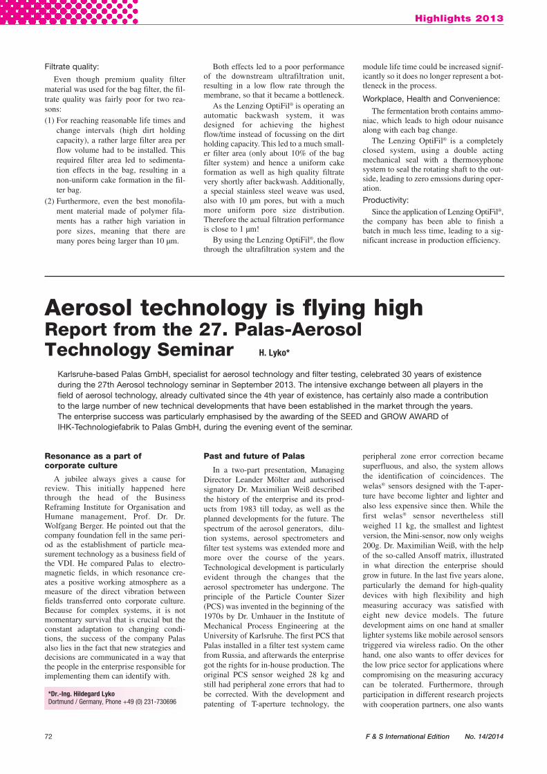
and Optimisation of Nanoparticle andNanostructure Production by ElectricalDischarges), in which he works togetherwith Palas and the IUTA, inter alia. Thefunction principle of electrical discharge isschematically shown in Fig. 1. The sparkthat originates between two electrodes, onaccount of the high temperature at thispoint, leads to the evaporation of elec-trode material and the vapour is drivenfrom the gap through the accompanyinggas stream and condenses to particles inthe order of magnitude of a few nm,which, in the further flow course assembleinto agglomerates. As materials, in princi-ple all electrically conductive materials areacceptable. Through the use of mixtures ofmaterials as the electrodes (alloyed or sin-tered, two different electrodes) mixed par-ticles can also be produced. The size of theprimary particles is adjusted via the sparkenergy, the gap width between the elec-trodes and the inert gas flow rate. If onewants to prevent agglomeration, one mustdilute the particle cloud. However, one canalso produce spherical particles to 100 nmdiameter by aggregation and fusion of theprimary particles in a heating track.
The objective of BUONAPART-E weresystems for the production of particle vol-umes in the order of magnitude of 5 kg perday. One increases the production volumeby an increase of the repetition frequencyof the electric spark per electrode pair andby parallel connection of several electrodepairs. Moreover, the frequency increasehas no influence on the resulting particlesas long as it is ensured that successive par-ticle clouds do not touch. The repetitionfrequency could be increased within thescope of the EU project by the factor of a100. The decisive factor was the develop-ment of new electronic switches andappropriate switching circuits.
Analysis of nanoparticle aerosols
As already explained in reports of pastATS, nanoparticles are counted by increas-ing the particle size by condensation of aworking fluid and afterwards supplyingthem to an optical sensor. Dr. Maximilian
Weiß explained the special features of thePalas UF-CPC in comparison to condensa-tion nucleus counters of other manufactur-ers that consist, in detail, in the feed of theworking fluid, the special features of theoptical sensor as well as in the volumeflow control. The working fluid, Butanolor water, is actively being transported intothe saturator via a spiralling U-channel,with other devices, the aerosol flows alonga saturated fleece. In the first case, theexchange of the working fluid is simplypossible because no residues can remain inthe saturator. The optical sensor is operat-ed with a LED as a light source, the mea-suring volume is limited thus that a singleparticle counting is possible also at highconcentrations. This is not the case withsensors with which the entire aerosol vol-ume passing through a laser light sheet isrecorded. Via the variation of the volumeflow, the Cut-Off (this is, the diameterwith which the countable efficiencyamounts to just about still 50%) can beshifted.
Depending on the surface properties ofthe particles, different particle numberscan be measured. While Butanol condens-es on nearly every particle, this is validwith water only in a limited manner, how-ever, this is the more ecologically friendlyworking means, particularly for applica-tion of the measurement technology ininterior settings. Depending on particlematerial, working fluid, the temperaturesin the saturator and capacitor and the vol-ume flow, one expects different diametersof the condensed drops and an influenceon countable efficiency course and Cut-Off diameter. The experimental determina-tion of these contexts i.e. the thermody-namic characterisation of a condensationnucleus particle counter by Palas, was car-ried out in a work by Susanne Baltzer atthe Institute for Mechanical ProcessEngineering and Mechanics at theKarlsruhe Institute of Technology. Forthis, an experimental plant was used, inwhich a neutralised aerosol generated by aspark generator or an atomizer is classifiedin a DEMC and is supplied in parallel,either as a mono-or - polydisperse aerosol,
Highlights 2013
F & S International Edition No. 14/2014 73
Fig. 1: Schematic diagram of nanoparticle production by sparkdischarge
Fig. 2: Schematic diagram of TXRF- method with a standing wave field
02_fs_international_2014_seite_03-98__ 21.05.14 20:11 Seite 73
to the CPC and a Faraday cup electrome-ter. In the tests described by Mrs. Baltzer itwas found that the drop diameter increasedwith increase of the difference in tempera-ture between saturator and capacitor,reduction of the aerosol volume flow andwith increase of the aerosol particle diam-eter in the Cut-Off area. At the same time,the increase of the difference in tempera-ture and the reduction of the volume flowcause a reduction of the Cut-Off diameteri.e. the measuring range is shifted towardssmaller particle diameters. An improvedchemical compatibility of the materialcombination particles-working fluid works
along the same lines. Overall, such studiesallow a better adaptation of the measure-ment system to certain materials.
Angle-dependent X-ray fluorescenceanalytics (TXRF) is a measuring methodwith which one can also determine thechemical composition of substance sam-ples, besides particle size and particle con-centration. It was explained by Dr. StefanSeeger, Federal Institute for MaterialsResearch and Testing, who had furtherdeveloped this method for automated insi-tu-characterisation of aerosols, togetherwith the Physikalisch Technische Bundes -anstalt and the measurement instrument
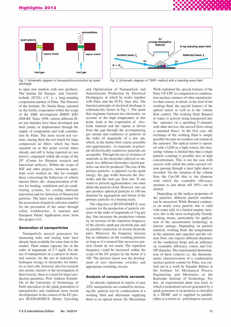
manufacturer Bruker. If one irradiatesmaterial samples with X-rays, the radia-tion is reflected with an energy typical forthe respective chemical element. By vary-ing the angle of incidence of such a raygradually in the range below the criticalangle of the total reflection, a standingwave field originates (see. Fig. 2). For aparticle within this wave field, the courseof the excitation intensity over the angle ofincidence is dependent on the size i.e. howmany antinodes and nodes of the wave“grid” made from strips of high and lowradiation intensity are covered by this par-ticle. With the angle scan, one can deriveconclusions about the particle size fromthe steepness of the leading edge and fromthe position of the first intensity maximumand conclusions about the volume of thedetected samples can be drawn from thesurface underneath the curve. Since thisprocess is not a method for analysing aparticle collective flying past in samplingpipes insitu and in real time, a suitable sys-tem was developed with which the sam-pling on a substrate in which the TXRFmethod is carried out is automated.Moreover, models had to be developed forthe interpretation of the signal courses andbe verified on the basis of reference sam-ples collected by impaction. This part ofthe development was undertaken by PTBand BAM on the measuring stationBESSY II of PTB. Bruker was responsiblefor development of the hardware for amobile TXRF device for which - besidethe components for the actual measure-ment as previously described - a gas purgefor the measurement and a sample chang-er for a maximum of 96 aerosol sampleswere provided. Important applications forthis measurement technology are theanalysis of complicated ambient aerosolsand workspace aerosols as are emitted, forexample, by laser printers or weldingmachines.
Supply and analysis ofbioaerosols
Bioaerosols contain biological materialsuch as endotoxins, viruses, bacteria, fun-gal spores, pollen and plant residues andare identified - beside with the parameters
74 F & S International Edition No. 14/2014
Highlights 2013
Tab. 2: National and European measurement campaigns for the detection of aerosols in ambient air
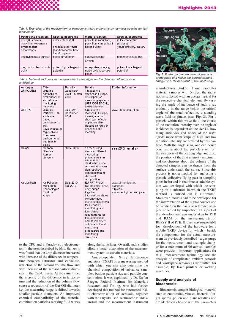
Fig. 3: Post-colorized electron microscopephotograph of a native bio-aerosol sample(Image: von-Thünen-Institut, Braunschweig)
Tab. 1: Examples of the replacement of pathogenic micro organisms by harmless species for testbioaerosols
02_fs_international_2014_seite_03-98__ 21.05.14 20:11 Seite 74

also decisive in inorganic aerosols - alsoby the biological activity of their compo-nents. Because biological activity isessential for different questions,bioaerosols often cannot be replaced byinorganic aerosols for research purposesand test purposes. Dr. Marcus Clauß fromthe Thünen-Institute in Braunschweigdeals with the requirements for testbioaerosols, their production and disper-sion as well as the applicable measurementtechnology. One example for a bioaerosolis shown in Fig. 3. Components ofbioaerosols for test purposes should haveno sensitising or toxic effect, however,they should have similar properties liketheir pathogenic relatives. Table 1 shows aselection of organisms which would besuitable for this. In addition, processeddust from henhouses is also used.
For the application of the bioaerosols,the tenacity (survival ability) of the organ-isms is vital. Because these also depend onthe measures for cultivation, production ofsuspensions or piles and for their trans-portation in the airborne state, these stepsmust be documented and be carried outaccording to the standard protocols as faras possible. Brush dosers are in principlealso suited for the dispersing, if this con-cerns dry particulate materials, or com-pressed air atomizers are suited for the dis-persing of suspensions; in the process,however, stress is exercised on the organ-isms. A more recent development for thenebulization of suspensions is a modified“Bubbling Aerosol Generator“, which isdescribed in Simon et al. /2/ . For particlemeasurement, it is also possible to resortto established methods, wherein the opti-cal particle counting, however, does notdetect the individual species. The fastestdetection, here, is in the collection on adhe-sive silicone surfaces and subsequent fluo-rescence microscopy with which the activ-ity of the cells is detectable in addition.
The measurement of the concentrationsof germs in living rooms and in work-spaces for risk assessment and verificationof the observance of any limit values,according to the statements of AnjaKonlechner, University of AgriculturalSciences Vienna, is not as unambiguous aswould be necessary. Since one receives,according to collector device and analysismethod, different results, whereby theactual particle number cannot be deter-mined because of the unknown device-specific losses, moreover, during the cul-tivation on a culture medium, only livinggerms are detected. To be able to comparecollector devices with each other a cali-brating chamber was designed togetherwith Palas and then built, in which, ideal-ly, a consistent, uniform particle concen-tration should be present. An aerosol isdosed into the accordingly purified supply
air, the concentration of which was mea-sured on the inside with particle countersin 3 different heights in nine different posi-tions. For this validation, an inorganic testdust was transferred into the air flow witha brush disperser. The particle concentra-tion in the chamber was not equal in allpositions but increased from top to bottomand with increasing distance from theaerosol dispenser, it decreased slightly,while the particle size distribution was thesame in all positions. Taking into accountthese concentration profiles, one stilldeemed the chamber suitable for compar-ing germ collection systems. However, forthe re-enactment of real bioaerosols, lowernumber concentrations would have to begenerated than is possible with the genera-tors used.
Particle analytics in the ambient air
Dr. Norbert Höfert, Commission on AirPollution Prevention in the VDI, reportedabout current developments and openquestions of particle measurement in theoutside air as well as about current mea-suring campaigns. While the Directiveseries VDI 3867 about counting measuringmethods was completed in 2013 with thepublication of the Folio 6 about the elec-trical low pressure impactor, the works onthe standardization of aerosol generatorsstill continue in the Directive series VDI3491 (cf. also /3/). However, the techno-logical developments led to the fact thatthe first folios of the VDI 3867 (from2008) have become outdated again.Currently, technical specifications forcounting measuring methods are beingpromoted at European level , among therest, on condensation nucleus counting. Tothis end, there is already a draft, publica-tion is aimed at for 2014. Such technicalspecifications define minimum require-ments for devices. They have a validity ofa few years and can, if necessary, be con-verted into a European Standard. The
development of standards happens in par-allel with different national and interna-tional measuring campaigns in which thepossibilities and the suitability of countingmeasuring methods are demonstrated for alonger period, and the effects of ultrafineparticles are examined (see Table 2).Beside the particle counting, the composi-tion of the particles will also be in thefocus in the subsequent programmes.
Not recorded in the table are furtherlocal measuring campaigns dealing, forexample, with the effect of environmentalzones on air quality. New possibilities arealso being opened up by unmanned aerialvehicles, which are equipped with mea-surement sensors. They serve the clarifica-tion of the aerosol emissions of certainsources and can elucidate their propaga-tion paths . For this purpose, two aerialvehicles were also demonstrated directlyat the conference venue. Firstly, an aerosolsensor was sent into the air, attached to aweather balloon , and the data collected byit could be traced on the screen in the con-ference room. On the other hand, the droneHORUS from Dresdner AirClip GmbH(see Fig. 4) was demonstrated, an ultra-light, remotely controlled element made ofcarbon fibre composite material, which,according to load capacity, is built asquadrocopter, octocopter or dodecacopter.
As a complete system for particlecounting with recording of all size frac-tions occurring in the outside air or evenindoors from 8nm to 40 μm, JürgenSpielvogel, Palas GmbH, presented thesystem U-Range. In this system, the twoequipment units U-SMPS with DEMC-size grader and the condensation nucleuscounter are combined with the fine dustmeasurement system Fidas. In each of the3.5 decades, up to 64 size channels can beresolved, moreover, the classical PM frac-tions can be detected in addition.
Limit values for the fine dust pollutionin the ambient air are still considered asmass concentrations and in spite of all
Highlights 2013
F & S International Edition No. 14/2014 75
Fig. 4: Octocopter HORUS with a Fidas Ultra-Light Sensor (Image: Palas GmbH)
02_fs_international_2014_seite_03-98__ 21.05.14 20:12 Seite 75
progress in the development of counting methods, the particle con-centration in the many environmental monitoring stations is alwaysalso detected gravimetrically. For the practical execution in thestate of Baden-Württemberg , this means that, in more than 50measuring stations of the State measurement network, filters haveto be collected daily and be equilibrated in the laboratory accord-ing to a routine required by the prEN12341 2012-02-10 (setting ofrel. humidity and temperature) and they also must be weighed. Dr.Harald Creutznacher of the responsible State EnvironmentalAgency pointed out the increase of the samples to be evaluated, tonearly 35,000 by 2011. To tackle them, an automatic weighing sys-tem was purchased and commissioned, with which 320 filters canbe weighed successively on 20 plates and a total of 640 filters canbe equilibrated at the same time. Every individual filter is auto-matically encoded so that it is assigned to a date and measuring sta-tion. By manual and automatic parallel weighings, it was shownthat the failure rate of the machine with about 2%, by faulty cod-ing / detection, is slight and that these errors can be avoidedthrough plausibility checks by the laboratory staff.
Anja Baum of the Federal Highway Research Instiute reportedabout a special application case of the pollutant detection and mea-surement in ambient air. The object of the investigation was thelength-dependent aerosol composition in road tunnels. The mea-surements were carried out with the background that later on, inte-rior walls or internal fittings provided with TiO2- nanoparticleswould be able to be implemented, through which, under the effectof a suitable light source, the catalytic degradation of the nitrogenoxides emitted by motor vehicles can be effected. As a preparationfor this, the pollutant distribution was determined in the RudowerHöhe tunnel in Berlin, using an especially developed robot. This isa remotely steerable vehicle which is equipped with an aerosol col-lecting system and can take up different 19‘- measuring instru-ments. The first measurements showed that the nitric oxide con-centration throughout the tunnel length increases by a factor of up
76 F & S International Edition No. 14/2014
Highlights 2013
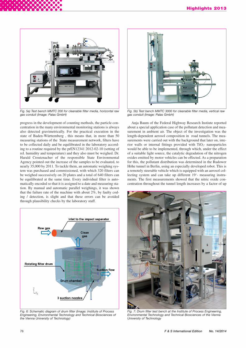
Fig. 5b) Test bench MMTC 3000 for cleanable filter media, vertical rawgas conduit (Image: Palas GmbH)
Fig. 5a) Test bench MMTC 200 for cleanable filter media, horizontal rawgas conduit (Image: Palas GmbH)
Fig. 7: Drum filter test bench at the Institute of Process Engineering,Environmental Technology and Technical Biosciences of the ViennaUniversity of Technology
Fig. 6: Schematic diagram of drum filter (Image: Institute of ProcessEngineering, Environmental Technology and Technical Biosciences ofthe Vienna University of Technology)
02_fs_international_2014_seite_03-98__ 21.05.14 20:12 Seite 76
to 15, while the particle concentration increases by a factor of 11,however, for particles > 1μm more prominently than for smaller ones.
Systems and examples for filter testing
The testing of filter media and complete filters according to thestandards applying for the respective product groups is implement-ed in different filter media test systems and filter test systems.Martin Schmidt, Palas, presented the individual versions andreported about new developments. As an example of the change offilter media testing with a changing standard, testing cleanable fil-ter media may be mentioned. VDI Directive 3926 describes twotest bench models, one each with horizontal and vertical raw gasconduit (cf. fig. 5a) and b)). The DIN ISO 11057, applying since2011, describes the test bench with vertical raw gas conduit as areference system, other measuring methods not explicitly exclud-ed, however, they must fulfil equivalence criteria. In an especiallydesigned test bench MMTC 3000 with two raw gas conduits, thedifferences are being examined together with Saxony TextileResearch Institute (STFI) within the scope of a ZIM project.
Another new development is a small compressed air filter testbench, the only measuring station where particle sizes and num-bers can be measured at a pressure of up to 7 bar. Besides finishedcompressed air filters, flat media, such as they as used in com-pressed air filters, can also be tested.
The small compressed air filter test system is constructed anal-ogously to the large measurement path at the IUTA, on which Dr.Wolfgang Mölter-Siemens has been conducting research on largecompressed air filters for some years. The object of the testsdescribed here was the temperature influence on the filtration prop-erties. The biggest part of the particles deposited are oil dropletscollecting in the filter medium, which are discharged into a reser-voir through a drainage layer. Because the viscosity of certain oils,with the temperature change by 30 – 40 K, changes by one orderof magnitude and the surface tension also drops clearly, a signifi-cant temperature influence was expected. The temperature depen-dence of the filtration properties was determined with immersion -saturated or aerosol-saturated filters with in each case fluctuatingor steady temperature. It was found that the pressure loss of the fil-ters correlated with the saturation degree and accordingly is notdependent on temperature, however, that the aerosol concentrationin the pure gas behind a saturated filter increases with temperature,something that one attributes to reentrainment (detachment andentrainment of already separated oil).
Dr. Frank Schmidt, University of Duisburg-Essen spoke on theinfluence of the relative humidity and the discrepancy between thefiltration output of room air filters or vehicle-interior filters if theyare tested at low (according to standard) or high relative humidity.The fact that high relative humidities significantly increase thepressure loss in the case of NaCl as a loading aerosol, the applica-tion of water droplets causes an extreme increase of the pressureloss and also the detachment of already deposited particles, hasalready been published in /5,6/. On account of these preliminaryexperiments, a new research project will start in 2014, which dealswith the filtration behaviour of gas turbine filters for offshore oper-ation.
Gas turbine filters must demonstrate high filtration and separa-tion efficiencies, even in harsh surroundings. The proof of the fil-ter quality is provided according to the Saudi Aramco Standard“32-SAMSS-008”. Dr. Dirk Renschen reported about constructionand commissioning of such a filter test bench. The details are pub-lished here on pages 85 - 88.
Detecting the fading behaviour of an aerosol in an indoor spacecaused by a indoor air cleaner is to be regarded in principle as afilter test, too. Such indoor air cleaner are used, for example, inChina for the reduction of exposure to both particles and gaseousair pollutants in indoor spaces. Hartmut Finger, IUTA, conducted
the testing according to the Chinese standard GB/T 18801-2008,and used cigarette smoke as a test aerosol. The particle concentra-tion in the test chamber decays exponentially and the fading coef-ficient, with air cleaner in operation, as expected, is higher than thenatural the fading coefficient (natural decrease of particles oradhering to walls). For an indoor air filter equipped with a certainfilter, the generateable clean air volume flow CADR (for: clean airdelivery rate) is measured, into which the fading coefficient and thevolume of the test room are integrated. These coefficients andhence also the CADR value can also be determined separately forcertain particle size fractions . With respect to the electrical outputof the device, its cleansing performance arises from this as a qual-ity feature for comparing different devices.
Development of filter media and filters
For the application of filter media, not only pressure loss andseparation efficiencies play a role but also the operational safety.Thorsten Stoffel, Gea Heat Exchangers, described the disastrousconsequences of flying sparks, as arises, for example, when weld-ing, for filter systems. Synthetic standard filter media are consid-ered to be highly flammable construction materials and conven-tional flame retardant equipment is often toxic. With GEAFireTex,he presented a new filter medium that has been classified into classB1according to a fire shaft test pursuant to DIN 4102-1:1998-05(Standard for the fire behaviour of building materials). This classi-fies the medium as flame retardant, that is the material does notburn completely after edge ignition and no burning ingredients willdrip or fall off. According to the DIN 5510-2-2009-5 for preventivefire protection in railway vehicles, the material is characterizedwith the flammability class S4, the drop forming capacity classST2 and the smoke development class SR2. In addition, theFireTex®- filter mats have been certified according to the lateststandard EN 45545-2:2013-08 (fire protection of railway vehicles)in accordance with requirements set R5 category “HL3”and there-fore suitable without restriction, according to the latest standard,for air conditioning systems of railway wagons. The requirementsmade there are even clearly undercut.
Johannes Wolfslehner, Vienna University of Technology,described his works on the modification of a drum filter for dustseparation. The function principle of such a filter, which is usedparticularly in the textile industry and tobacco industry for highvolume flows with low concentration of fibrous dusts, is evidentfrom Fig. 6. In its original design with flat sheet filter media withhigh air permeability, the deposition of nanoparticles is not suffi-cient. Therefore, filtration experiments with pleated filter media -which have lower air permeability, however, higher separation
Highlights 2013
F & S International Edition No. 14/2014 77
02_fs_international_2014_seite_03-98__ 21.05.14 20:12 Seite 77
Compressed air qualities
Since 2010, the new version of ISO8573-1 is valid, in which the quality class-es are defined for compressed air, namelyseparately for contaminants particles,water (vapour) and oil (vapour).Accordingly, the quality classes are alsospecified as the combination of three dig-its (2.3.1 means: Class 2 for particulatepollution, Class 3 for humidity and Class 1for oil). In comparison to the previouslyapplicable version ISO 8573-1:2001 (see/1/), it is noticeable that the limit values forparticles in Classes 1 - 5 have not fallen,but risen. This development is contrary tothe experience often observed that newerstandards also include stricter limit valuesaccording to the technological advance-
ment of components and test instruments.In the new standard, on the other hand,more stringent requirements without gen-eral specification are categorized in Class0. As the enterprise Parker DomnickHunter advises in a brochure, the require-ments for Class 0 must be defined in writ-ing between the operator and device man-ufacturer. Moreover, they must beverifiable with the test methods or mea-surement methods described in Parts 2 to 9of ISO 8573. This will provide users withhigh quality standards the possibility ofgetting compressed air quality tailor-madefor their application.
The compressed air quality classes > 5(apart from humidity) are rather uninter-esting in view of the application of treat-ment techniques, and they are not to befound in more demanding applications.Table 2 gives an overview of which quali-
ty classes are possible for what kind ofapplication, namely as is communicatedby Omega Air GmbH in Moers.
To give consumers of compressed air apossible orientation about the qualitiesrequired for their applications, at theVDMA they are currently working on thecreation of a new Standards Sheet /3/, inwhich, on the basis of the revised ISO8573-1:2010, typical compressed air qual-ities for different uses are indicated, aswell as measures to achieve these quali-ties, to monitor them and to uphold themby means of maintenance works. In addi-tion, attention is paid to energy efficiency.
Efficiency of compressed airsystems
On average, an efficiency increase of33% and an effectiveness increase of 25%are considered feasible for industrial com-
78 F & S International Edition No. 14/2014
Highlights 2013
Energy-efficient generation and treatment of compressed air Report from COMVAC 2013 H. Lyko*
As an international, leading trade fair for compressed air and vacuum technology, ComVac has been an independentpart of the Hanover Trade Fair since 2005. Both compressed air and vacuum technology are technologies in whichenergy and resource efficiency are an important trend, and one that is crucial in competition. This is partly because, forexample, the use of compressed air is indispensable in almost any industrial plant. The VDMA Blue Competence sustainability initiative is also considering the trend towards the increase of energy andresource efficiency of this technology. The VDMA Association Compressors, Compressed Air and Vacuum Technology,as conceptual sponsor of the trade fair, supports users in this area, among others, with tools such as the EcoLexikonand the Compressed air model computer. The EcoLexikon offers an informal introduction to the comprehensiveoperation of compressed air and vacuum technology to the users. With the interactive Compressed air modelcomputer, the energy consumption and saving potentials of a compressed air system are determined. A large numberof components illustrated, especially compressors, but also filters and other processing equipment units, shouldconform to the requirements of greater efficiency and sustainability. Improved Process Control and Instrumentation alsomake their contributions.
efficiencies of nanoparticles - were carried out on the test benchshown in Fig. 7. As filter media , one medium with aluminiumfibre web and one medium with ePTFE membrane were selected.Because of the clearly bigger filter area, the filter face velocitycould be reduced so that the same pressure loss level could be keptas with a flat sheet medium. Here, the biggest challenge arose inthe implementation of the cleaning through the externally mount-ed extraction nozzles. This was reflected in the substantial increaseof the residual pressure loss causes by insufficient cleaning in thepleated depths. Here, measures are planned for the adaptation ofthe nozzle geometry and the cleansing strategy.
Literature:/1/ Bankodad, A. et al.: Verfahren zum Bestimmen des Eindringens von Prüfpartikeln in einen
Messbereich; DE102008029700A1 (2010)/2/ Simon, X. et al.; Aerolisation of Escherichiacoli and associated endotoxin using an
improved bubbling bioaerosol generator; Journal of Aerosol Science 42 (2011) 517 -531
/3/ Lyko, H.: Filterprüfung, Emissionsüberwachung, Luftreinhaltung, Wolken- undKlimaforschung: vielfältige Einsatzmöglichkeiten für Aerosoltechnologie – Report on 26.Palas ATS; F&S Filtrieren und Separieren 26(2012) No. 6, p. 409 – 414
/4/ Birmili, A. et al: Atmospheric aerosol measurements in the German Ultrafine AerosolNetwork (GUAN) – Part 1: Soot and particle number size distributions; Gefahrstoffe –Reinhaltung der Luft 69 (2009) No. 4, p. 137 – 145
/5/ Schmidt, F; Breidenbach, A; Suhartiningsih: Der Druckverlust von Luftfiltern bei hohen rel-ativen Feuchten und bei Beaufschlagung mit Wassertröpfchen; F&S Filtrieren undSeparieren 27 (2013) No.1, p. 6-9
/6/ Schmidt f.; Breidenbach, A.: Vergleichende Prüfung von KFZ-Innenraumfitlern, F&S GlobalGuide of the Filtration and Separation Industry (2012-2014) ISBN: 978-3-00-037568-2;p. 256 – 262
/7/ Renschen, D.; Schamberg, J.; Guttenbrunner, N.; Schneider, N.: HalbautomatischePrüfung von Gasturbinenansaugfiltern nach dem ARAMCO-Standard und zurLeistungsoptimierung; F&S Filtrieren und Separieren 27(2013) No. 6, pp. 374 – 378
/8/ Renschen, D.; Schamberg, J.; Guttenbrunner, N.; Schneider, N.: Semi-Automated GasTurbine Inlet Filter Testing According ARAMCO Standard or for Performance Optimization;Presentation at Filtech 2013, October 22-24th, Wiesbaden, Germany
*Dr.-Ing. Hildegard LykoDortmund / Germany, Phone +49 (0) 231-730696
02_fs_international_2014_seite_03-98__ 21.05.14 20:12 Seite 78