
AEROELASTIC ANALYSIS OF SPHERICAL...
12
11th World Congress on Computational Mechanics (WCCM XI) 5th European Conference on Computational Mechanics (ECCM V) 6th European Conference on Computational Fluid Dynamics (ECFD VI) E. Oñate, J. Oliver and A. Huerta (Eds) AEROELASTIC ANALYSIS OF SPHERICAL SHELLS A. A. LAKIS * , M. MENAA * AND M. TOORANI † * Mechanical Engineering Department Ecole Polytechnique of Montreal Montreal (QC), Canada e-mail: [email protected] [email protected] † Mechanical System Engineering Conestoga College Cambridge (ON), Canada email: [email protected] Key Words: Spherical Shell, Aeroelastic, Supersonic airflow, Flutter Abstract. This paper addresses the aeroelastic analysis of a spherical shell subjected to external supersonic airflow. The structural model is based on a combination of the linear spherical shell theory and the classic finite element method. The finite element is a spherical frustum instead of the usual rectangular shell element. In this hybrid method, the nodal displacements are found from the exact solution of shell governing equations rather than approximated by polynomial functions. Linearized first-order potential (piston) theory with the curvature correction term is coupled with the structural model to account for pressure loading. The linear mass, stiffness, and damping matrices are found using the hybrid finite element formulation by exact analytical integration of equations of motion. The aeroelastic equations of motion are reduced to a standard eigenvalue problem. The flutter boundary is found by analyzing the real and imaginary parts of the eigenvalues as the freestream pressure is varied. The results are validated using the numerical and theoretical data available in literature. The analysis is accomplished for spherical shells with different boundary conditions, geometries, flow parameters, and radius to thickness ratios. The results show that the spherical shell loses its stability through coupled-mode flutter. The proposed hybrid finite element formulation can give the reliable results at less computational cost compared to commercial software. 1 INTRODUCTION Shells of revolution are one of the primary structural elements in the aerospace structures. Their applications include the propellant tank or gas-deployed skirt of spacecraft. Due to the aerodynamic shape combined with thin wall thickness, spherical shells are more disposed to dynamic instability or flutter induced by high Mach number gas flow. It is, therefore, important to understand the effect of different flow parameters and loadings on the dynamic response of these structures. The aeroelastic analysis of shells and plates has been experimentally and analytically studied by numerous researchers [1]. Dowell gives an extensive study of the aeroelasticity of shells and plates in his book [2]. After introducing the application of piston theory in the aeroelastic modeling presented by Ashley and Zatarian [3], a number of interesting experimental and
Transcript of AEROELASTIC ANALYSIS OF SPHERICAL...

11th World Congress on Computational Mechanics (WCCM XI)5th European Conference on Computational Mechanics (ECCM V)
6th European Conference on Computational Fluid Dynamics (ECFD VI)E. Oñate, J. Oliver and A. Huerta (Eds)
AEROELASTIC ANALYSIS OF SPHERICAL SHELLS
A. A. LAKIS*, M. MENAA
* AND M. TOORANI†
* Mechanical Engineering DepartmentEcole Polytechnique of Montreal
Montreal (QC), Canadae-mail: [email protected]@polymtl.ca
† Mechanical System EngineeringConestoga College
Cambridge (ON), Canadaemail: [email protected]
Key Words: Spherical Shell, Aeroelastic, Supersonic airflow, Flutter
Abstract. This paper addresses the aeroelastic analysis of a spherical shell subjected to external supersonic airflow. The structural model is based on a combination of the linear spherical shell theory and the classic finite element method. The finite element is a spherical frustum instead of the usual rectangular shell element. In this hybrid method, the nodal displacements are found from the exact solution of shell governing equations rather than approximated by polynomial functions. Linearized first-order potential (piston) theory with the curvature correction term is coupled with the structural model to account for pressure loading. The linear mass, stiffness, and damping matrices are found using the hybrid finite element formulation by exact analytical integration of equations of motion. The aeroelastic equations of motion are reduced to a standard eigenvalue problem. The flutter boundary is found by analyzing the real and imaginary parts of the eigenvalues as the freestream pressure is varied. The results are validated using the numerical and theoretical data available in literature. The analysis is accomplished for spherical shells with different boundary conditions, geometries, flow parameters, and radius to thickness ratios. The results show that the spherical shell loses its stability through coupled-mode flutter. The proposed hybrid finite element formulation can give the reliable results at less computational cost compared to commercial software.
1 INTRODUCTION
Shells of revolution are one of the primary structural elements in the aerospace structures. Their applications include the propellant tank or gas-deployed skirt of spacecraft. Due to the aerodynamic shape combined with thin wall thickness, spherical shells are more disposed to dynamic instability or flutter induced by high Mach number gas flow. It is, therefore, important to understand the effect of different flow parameters and loadings on the dynamic response of these structures.
The aeroelastic analysis of shells and plates has been experimentally and analytically studied by numerous researchers [1]. Dowell gives an extensive study of the aeroelasticity of shells and plates in his book [2]. After introducing the application of piston theory in the aeroelastic modeling presented by Ashley and Zatarian [3], a number of interesting experimental and

A. A. Lakis, M. Menna, M. Toorani
theoretical studies were carried out to investigate the supersonic flutter of cylindrical shells. In general, all of this research was concerned with the development of an analytical relation to describe the effect of shell and flow parameters on the critical flutter dynamic pressure. Aeroelastic models, in combination with linear or nonlinear piston theory, were coupled to the theory of shells to account for the fluid-structure interaction. The resulting governing equations were treated numerically using the Galerkin’s method. A comprehensive experimental test was done by Fung and Olson [4]. They studied the effects of shell boundary conditions and the initial stress state due to the internal pressure and axial load. It was observed that the pressurized cylindrical shell fluttered at a lower level of free-stream static pressure than predicted by theory [5]. Later, Evensen and Olson [6, 7] presented a nonlinear analysis to take this observed effect into account. Dowell [8] also analyzed the behavior of a cylindrical shell in supersonic flow for different flow and shell parameters. A complete description of panel flutter modeling is given in his book [2].
An analytical approach to the supersonic flutter of a spherical shell becomes very complicated if one wishes to include different parameters. Therefore, the efficiency of numerical methods such as the finite element method (FEM) is an advantage for cases involving changes to all factors affecting flutter boundaries. The aim of the present study is to develop a hybrid finite element method in order to predict the aeroelastic behavior of isotropic spherical shells with different parameters such as boundary conditions, geometries, flow parameters, and radius to thickness ratios. The finite element is a spherical frustum instead of the usual rectangular shell element. The linear thin shell theory is coupled with the linear piston theory. The linear mass, damping, and stiffness matrices are analytically obtained. The aeroelastic equation of motion is reduced to a standard eigenvalue problem. The flutter boundary is found by analyzing the real and imaginary parts of the eigenvalues as the freestream pressure is varied.
2 FORMULATION
2.1 Structural Modeling
In this study the structure is modeled using a hybrid finite element method, which is a combination of the spherical shell theory and the classical finite element method. In this hybrid finite element method, the displacement functions are found from the exact solution of the spherical shell theory, rather than approximated by polynomial functions as is done in the classical finite element method. In the spherical coordinate system (R,h,/) shown in Fig. 1, five out of the six equations of equilibrium derived in Ref. [9] for spherical shells are written as follows
2

A. A. Lakis, M. Menna, M. Toorani
( )
( )
1cot 0
sin
12 cot 0
sin
1cot ( ) 0
sin
1cot 0
sin
12 cot 0
sin
N NN N Q
N NN Q
Q QQ N N
M MM M RQ
M MM RQ
φ φ θφ θ φ
φ θ θφ θ θ
φ θφ φ θ
φ φ θφ θ φ
φ θ θφ θ θ
φφ φ θ
φφ φ θ
φφ φ θ
φφ φ θ
φφ φ θ
∂ ∂+ + − + =
∂ ∂∂ ∂+ + + =
∂ ∂∂ ∂+ + − + =∂ ∂
∂ ∂+ + − − =
∂ ∂∂ ∂+ + − =
∂ ∂ (1)
where N, N, and N are membrane stress resultants, M, M, and M are the bending stress resultants, and Q and Q are the shear forces (see Fig. 2). The sixth equation, which is an identity equation for spherical shells, is not presented here. A system of equilibrium equations can be obtained as a function of displacement functions and material properties [Pij] (See Ref. 10 for more details)
(2) The element is a circumferential spherical frustum shown in Fig. 3. It has two nodal circles with four degrees of freedom; axial, radial, circumferential and rotation at each node. This element type makes it possible to use thin shell equations easily to find the exact solution of displacement functions rather than an approximation with polynomial functions as done in classical finite element method. For motions associated with the nth circumferential wave number we may write:
(3)
3

A. A. Lakis, M. Menna, M. Toorani
The transversal displacement can be expressed as: (4)
Where (5)
And where, are the associated Legendre functions of the first and second kinds respectively of order n and degree. The expression of axial displacement is given as:
(6)
where the coefficient Ei
and the auxiliary function ψ (which is a function of Legendre
functions) are given in [10]. Finally the circumferential displacement is given as:
(7)Using matrix formulation, the displacement functions can be expressed as follows:
(8)The matrix [R] is given in [10]. The vector is given by the following expression:
(9)
In the finite element method, the vector C is eliminated in favor of displacements at elements
nodes. At each finite element node, the three displacements (axial, transversal and
circumferential) and the rotation are applied. The displacement of node i are defined by the
vector:
4

A. A. Lakis, M. Menna, M. Toorani
(10)
The element in Fig. 3 with two nodal lines (i and j) and eight degrees of freedom will have the
following nodal displacement vector:
(11) The terms of matrix and are given in the [10]. Now, pre-multiplying by equation (11) one obtains the matrix of the constant Ci as a function of the degree of freedom:
(12)
Finally, one substitutes the vector into equation (8) and obtains the displacement functions as follows:
(13)The strain vector can be determined from the displacement functions and the deformation–displacement relations as:
(14)
where matrix is given in [10]. Based on the finite element formulation, the local stiffness and mass matrices are:
(15)Where the density and h is the thickness of shellThe surface element of the shell wall is. After integrating over, the preceding equations become
(16)In the global system the element stiffness and mass matrices are
(17)The terms in matrix [LG] are given in Ref. [10].
From these equations, one can assemble the mass and stiffness matrix for each element to obtain the mass and stiffness matrices for the whole shell: and. Size of each elementary matrix is , therefore the final size of and will be where N is the number of elements in the model.
2.2 Aerodynamic Modeling
Piston theory, introduced by Ashley and Zartarian [3], is a powerful tool for aeroelasticity modeling. In this study the fluid-structure effect due to external pressure loading can be taken into account using the linearized first-order potential theory. This pressure is expressed as
5
A. A. Lakis, M. Menna, M. Toorani
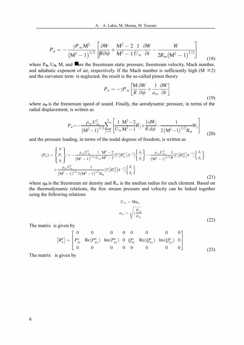
(18)where P, U, M, and are the freestream static pressure, freestream velocity, Mach number, and adiabatic exponent of air, respectively. If the Mach number is sufficiently high (M 2) and the curvature term is neglected, the result is the so-called piston theory
(19)where a is the freestream speed of sound. Finally, the aerodynamic pressure, in terms of the radial displacement, is written as
(20)and the pressure loading, in terms of the nodal degrees of freedom, is written as
(21)where q is the freestream air density and Rm is the median radius for each element. Based on the thermodynamic relations, the free stream pressure and velocity can be linked together using the following relations
(22)The matrix is given by
(23)The matrix is given by
6

A. A. Lakis, M. Menna, M. Toorani
(24)where matrix [C] is given by [10]. The general force vector due to a pressure field is written as
(25)Substituting the structural shape functions (Equation 13) and pressure loading (Equation 21) into equation (25) and carrying out the exact analytical integration over the area, we can derive the local damping and stiffness matrices due to aerodynamic loading. The local damping matrix is given by
(26)Finally the local stiffness matrix is given by
(27)In the global system, the element damping and stiffness matrices Are
7

A. A. Lakis, M. Menna, M. Toorani
(28)From these equations, one can assemble the damping and stiffness matrices for each element in order to obtain the damping and stiffness matrices for the whole shell: [Cf] and [Kf]. The governing equation, which accounts for the fluid-shell interaction in the presence of the external supersonic airflow, is derived as
(29)where subscripts ‘s’ and ‘f’ refer to shells in vacuo and fluid, respectively.
3 EIGENVALUE PROBLEM
The global fluid matrices mentioned in Eq. (29) may be obtained, respectively, by superimposing the damping and stiffness matrices for each individual fluid finite element. After applying the boundary conditions, the global matrices are reduced to square matrices of the order , where N is the number of finite elements in the shell and J is the number of constraints applied. Finally, the eigenvalue problem is solved by means of the equation reduction technique. Equation (29) may be rewritten as follows
(30)Where
(31)Here, {} is the global displacement vector, and [Cf] and [Kf] rep resent the damping and elastic forces induced by the flowing fluid. The eigenvalue problem is given by
(32)Where
(33)Here, and [I] is the identity matrix. An in-house computer code based on the finite element method was developed as part of this work to establish the structural and fluid matrices of each element based on equations developed using the theoretical approach. The calculations for each finite element are performed in two stages: the first dealing with the solid shell and
8

A. A. Lakis, M. Menna, M. Toorani
the second with the effect of the flowing fluid. The aeroelastic stability will be examined by studying the eigenvalues in the complex plane. When the imaginary part of becomes negative, the amplitude of the shell motion grows exponentially with time, thus indicating dynamic instability. The flutter boundary is numerically obtained by tracing the eigenvalues to see when the sign of the imaginary part just changes from positive to negative. For the fixed value of the circumferential wavenumber n, the onset of instability is determined by varying the value of the freestream static pressure. This procedure is repeated for different values of ‘n’ until the minimum critical pressure is obtained.
4 RESULTS AND DISCUSSIONS
spherical shell with . Kraus [9] investigated the case of a simply supported spherical shell using a general theory, which included the effects of transverse shear stress and rotational inertia. For cases both with and without these effects, he determined the natural frequencies for the shell motion that was independent of for the circumferential mode number n=0. Tessler and Spiridigliozzi [11] and Gautham and Ganesan [12] analyzed the case of the clamped hemispherical shell. The natural frequencies for clamped and simply supported spherical shells were computed in the present method (using only 12 elements). The results are shown, respectively, in Tables 1 and 2.
Table 1: Normalized natural frequencies for 90 degrees clamped spherical shell with R/h=10
Mode Ref. [11] Ref. [12] Present Theory1 0.8481 0.8439 0.83272 1.2328 1.2317 1.19193 1.5902 1.5808 1.50414 1.9435 1.9267 1.9161
Table 2: Normalized natural frequencies for 90 degrees simply supported spherical shellMode Ref. [22],
(R/h/=50)Present Theory (R/h=50)
1 0.7548 0.75792 0.9432 0.90343 1.0152 0.94994 1.1082 1.10895 1.2523 1.27596 1.4576 1.47237 1.6558 1.62378 1.7636 1.7634
The next example deals with studying the flutter boundary. Flutter, which is observed in all of the papers using piston theory, is a coupled-mode flutter. Indeed, let us consider the motion of the shell eigenvalues in the complex plane. If the freestream pressure is not very high and the shell is stable, all complex frequencies are located in the top half-plane. Increasing the
9

A. A. Lakis, M. Menna, M. Toorani
freestream pressure, the first and the second complex frequencies move toward each other, almost merge, and then go away from each other in vertical directions (see Fig. 4), thus, the interaction of the two modes occurs. Physically, this interaction of the shell modes happens through the effect of the air flow. A simply supported spherical shell with is treated here. The complex frequencies, only for the first and second modes, versus the freestream dynamic pressure are plotted in Fig. 5. The aerodynamic pressure is evaluated using Eq. (18). In Fig. (5a) the real part of the complex frequency increases for the first mode, while for the second mode it decreases as the freestream dynamic pressure parameter K increases. For higher values of dynamic pressure these real parts, representing the oscillation frequency, eventually coalesce into a single mode. Further increasing the dynamic pressure of the flow causes the shell to lose its stability at . This instability is due to the coupled-mode flutter where the imaginary part of the complex frequency (representing the damping term of the aeroelastic system) becomes zero for certain critical pressures (see Fig. (5b)). The same behavior is observed by the real and imaginary parts of complex frequencies as the static pressure increases (see Fig. 5c and 5d), but the onset of flutter is at if the freestream static pressure is evaluated using Eq. (19). The prediction of the critical freestream static pressure using Eq. (18) provides approximately the same results when evaluating the pressure field using Eq. (19). As expected, using the piston theory with the correction term to account for the shell curvature produces a better approximation for the pressure loading acting on a curved shell exposed to supersonic flow.
Figure 4: Trajectories of the complex frequencies loci in the complex plane during the changing of the dynamic pressure parameter
10

A. A. Lakis, M. Menna, M. Toorani
Figure 5: (‘a’ and ‘c’) Real part, and (‘b’ and ‘d’) the imaginary part of complex
frequencies versus the freestream static pressure parameters evaluated by equations (18 and 19)
5 CONCLUSIONS
An efficient hybrid finite element method is presented to investigate the aeroelastic stability of an empty spherical shell subjected to external supersonic flow. The linear shell theory is coupled with the first order piston theory to account for aerodynamic pressure. The effect of the curvature correction in piston theory was analyzed. The study has been done for shells with various geometries, radius to thickness ratios, and boundary conditions. In all of the study cases, one type of instability is found; the coupled-mode flutter in the first and second mode. Increasing the radius to thickness ratio leads the onset of flutter to occur at a higher dynamic pressure. Decreasing the angle of the spherical shell causes the flutter boundary to occur at a lower dynamic pressure. The proposed hybrid finite element formulation can give reliable results at less computational cost compared to commercial software since the latter imposes some restrictions when such an analysis is done.REFERENCES
[1] Bismarck-Nasr, M. N., Finite Elements in Aeroelasticity of Plates and Shells Appl. Mech. Rev., (1996) 49: S17–S24.[2] Dowell, E. H., Aeroelasticity of Plates and Shells, Noordhoff, Leyden (1975)[3] Ashley, H. and Zartarian, G., Piston Theory New Aerodynamic Tool for Aeroelastician J. Aeronaut. Sci., (1956) 23: 1109–1118
11

A. A. Lakis, M. Menna, M. Toorani
[4] Fung, Y. C., and Olson, M. D., Supersonic Flutter of Circular Cylindrical Shells Subjected to Internal Pressure and Axial Compression AIAA J., (1966) 4: 858–864[5] Fung, Y. C., and Olson M. D., Comparing Theory and Experiment for Supersonic Flutter of Circular Cylindrical Shells AIAA J., (1967) 5: 1849–1856[6] Evensen, D. A., and Olson, M. D., Nonlinear Flutter of a Circular Cylindrical Shell in Supersonic Flow (1967) NASA Technical Note No. D-4265[7] Evensen, D. A., and Olson, M. D., Circumferentially Traveling Wave Flutter of Circular Cylindrical Shell AIAA J., (1968) 6: 1522–1527[8] Dowell, E. H., Flutter of Infinitely Long Plates and Shells. Part II AIAA J., (1966) 4: 1510–1518[9] Kraus, H., Thin Elastic Shells, (1967) John Wiley and Sons, New York.[10] Menaa M. and Lakis A. A., Hybrid Finite Element Analysis of Free Vibration of a Spherical Shell Filled with Fluid, (2012) Ecole Polytechnique of Montreal[11] Tessler, A., and Spiridigliozzi, L., Resolving Membrane and Shear Locking Phenomena in Curved Deformable Axisymmetric Shell Element Int. J. Numerical Methods Eng., (1988) 26: 1071–1080[12] Gautham, B. P., and Ganesan, N., Free Vibration Characteristics of Isotropic and Laminated Orthotropic Shell Caps J. Sound Vibration, (1997) 204: 17–40
12


![SHAPING OF AIRCRAFT AND HELICOPTER CONFIGURATIONS …congress.cimne.com/iacm-eccomas2014/admin/files/filePaper/p188… · constructed with CATIA V5from Dassault Systemes , [8]. While](https://static.fdocuments.us/doc/165x107/5eab9cc2e9522856ad4df664/shaping-of-aircraft-and-helicopter-configurations-constructed-with-catia-v5from.jpg)


