Aerodynamics-Front & Rear Wings - Final Report · Aerodynamics-Front & Rear Wings - Final Report...
51
Transcript of Aerodynamics-Front & Rear Wings - Final Report · Aerodynamics-Front & Rear Wings - Final Report...


Aerodynamics-Front & Rear Wings - Final Report
by Mikael Sedlacek
2013-09-08
1

Aerodynamics-Front & Rear Wings - Final Report
by Mikael Sedlacek
2013-09-08
2
Abstract Grass grows, birds fly, waves pound the sand and wings deliver lift.
In 2013 Chalmers Formula Student set out to design and deliver a reliable yet lightweight formula
racing solution. To achieve this goal it was determined that negative lift was needed for the car to
have enough traction on the track. Thus it was decided to design and deliver a front and rear wing to
fit the application.
There is no definite way how to design wings for a race car because of the amount of variables that
affects aerodynamics. They are affected by the turbulent flow around the car created by the wheels
and body. Also in play is the ground effect which is not present in for instance airplane wings. So
when looking at aerodynamics for a race car one has to see it as a unified whole.
This report will present how the wings were designed and delivered by going through each phase of
the project. It will present the variables of each phase and give motivations for why certain choices
were made.
Aerodynamics-Front & Rear Wings - Final Report
by Mikael Sedlacek
2013-09-08
3
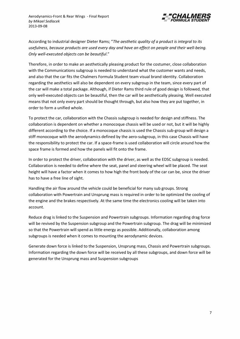
Contents Abstract ................................................................................................................................................... 2
List of figures and tables ......................................................................................................................... 4
1. Pre Study ......................................................................................................................................... 5
Introduction ......................................................................................................................................... 5
Functional model ................................................................................................................................. 6
Benchmarking ...................................................................................................................................... 8
Solution model .................................................................................................................................. 14
Final discussion .................................................................................................................................. 14
2. Design ............................................................................................................................................ 16
Technical Background ........................................................................................................................... 16
Analysis .................................................................................................................................................. 31
Material selection for the wings ....................................................................................................... 31
CFD ........................................................................................................................................................ 33
3. Manufacturing ............................................................................................................................... 34
4. Manufacturing coordination ......................................................................................................... 40
5. Costs .............................................................................................................................................. 44
6. Testing/ Validation ........................................................................................................................ 44
7. Improvements/ Conclusion/ Recommendation ............................................................................ 45
8. References ..................................................................................................................................... 46
9. Appendices .................................................................................................................................... 46

Aerodynamics-Front & Rear Wings - Final Report
by Mikael Sedlacek
2013-09-08
4
List of figures and tables Figure 1: Functional model ...................................................................................................................... 6
Figure 2: Undertray and Diffuser setup ................................................................................................. 11
Figure 3: The effect of an Airdam (Barnard, 2001) ............................................................................... 11
Figure 4: Solution model for Aerodynamics .......................................................................................... 14
Figure 5: This is a sketch made to illustrate the concepts evaluated during the pre-study phase. The
sketch is not at all a final design. ........................................................................................................... 15
Figure 6: Sketch of S1223 Airfoil with endplate .................................................................................... 16
Figure 7: Simplified figure of how an airfoil works ............................................................................... 17
Figure 8: Explanation of the key terms of an airfoil .............................................................................. 18
Figure 9: A sketch of the flow on an airfoil without endplates ............................................................. 19
Figure 10: A table with the design targets for the aerodynamic subgroup .......................................... 21
Figure 11: A CAD rendering of the parts current for this report ........................................................... 22
Figure 12: A picture of the flow field around the S1223 airfoil ............................................................. 23
Figure 13: A CAD rendering of the concept front wing without a middle segment.............................. 24
Figure 14: A CAD rendering of the concept with a neutral middle segment ........................................ 25
Figure 15: A CAD rendering of the concept with small end plates ....................................................... 26
Figure 16: A CAD rendering of the concept with endplates close to the chassis .................................. 26
Figure 17: A CAD rendering of the final front wing concept ................................................................. 27
Figure 18: A CAD rendering of the rear wing with a neutral middle segment ...................................... 29
Figure 19: A CAD rendering of the rear wing with plates in the middle ............................................... 29
Figure 20: A CAD rendering of the final rear wing concept .................................................................. 30
Figu e : A g aph ith ate ials ith ou g’s odulus plotted agai st de sit ............................... 32
Figure 22 A CAD of the top part of the front wing main element mold ............................................... 34
Figure 23 Twill weave Figure 24 Textreme weave ............................................................................. 35
Figure 25 A picture of using vacuum infusion for the top part of the rear wing .................................. 36
Figure 26 A picture of the ribs placed out on the top part of the wing ................................................ 37
Figure 27 Picture of a part of the BOM initially set up .......................................................................... 40
Figure 28 A picture of the overall planning document ......................................................................... 41
Figure 29 A picture of the overall planning setup ................................................................................. 42

Aerodynamics-Front & Rear Wings - Final Report
by Mikael Sedlacek
2013-09-08
5
1. Pre Study
Hereby a briefing of the pre study part of the project can be found. It involves a problem definition,
functional model, benchmarking, solution model and discussion revolving the same.
Introduction
In order to develop a concept it is first of all important to identify the main functions for the
subsystem. The functions are first presented in a functional model. In order to fulfil these functions,
data collection and benchmarking has been made to find existing solutions and developing new. The
identified concepts were then evaluated in order to choose the best alternatives, and these solutions
are then presented in a solution model.
1.1 Problem Definition
The main responsibilities for the Aero subgroup within Chalmers Formula Student is reducing drag
and creating down force. Drag refers to the resultant force acting in the stream wise direction, and it
has a direct effect on the fuel efficiency (Clayton, 2010). Down force refers to negative lift which pulls
the a do a ds. This ea s that the a ill e a le to ake o e effi ie t use of its ti es due to the i eased t a i g ge e ated do fo e. Opti al diffuse design for Formula SAE Race
Car) (Ehirim,2012,p.2) In addition to this cooling is to be generated for the engine and protection is to
be created for the driver and the car. The Aero subgroup is also responsible for the aesthetics of the
car.

Aerodynamics-Front & Rear Wings - Final Report
by Mikael Sedlacek
2013-09-08
6
Functional model
The functional model was created in order to identify the different functions which each separate
subgroup is responsible for. Thus the functional model for the aerodynamics subgroup can be found
underneath.
1.2 Presentation
By starting from the customer needs we can determent functions to be able to find solutions. The
functional model shows inputs and outputs to the system, e.g. air comes in and is used in order to
generate down force. Further on the model describes how the identified functions interact with
other subgroups and the boundaries between different subgroups.
Figure 1: Functional model
1.3 Explanations
The functions that the Aero subgroup are responsible for, is (1) the aesthetics of the car, which are
important in order to attract customers and create a winning concept. (2) To protect the car, focuses
mainly on the engine and (3) the driver during the race. (4) To create mass flow for cooling vital parts
of the vehicle, such as brakes and engine. (5) To reduce drag, which reflects on the performance and
the fuel efficiency of the vehicle. Additionally (6) to generate down force, improving the overall
handling and grip of the vehicle while it is cornering.
1.4 Discussion
Aerodynamics-Front & Rear Wings - Final Report
by Mikael Sedlacek
2013-09-08
7
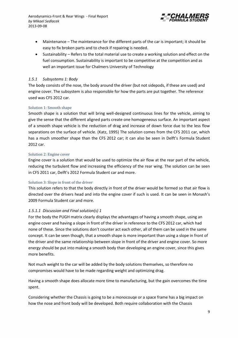
A o di g to i dust ial desig e Diete Ra s; The aesthetic quality of a product is integral to its
usefulness, because products are used every day and have an effect on people and their well-being.
Only well-executed objects can be beautiful.
Therefore, in order to make an aesthetically pleasing product for the costumer, close collaboration
with the Communications subgroup is needed to understand what the customer wants and needs,
and also that the car fits the Chalmers Formula Student team visual brand identity. Collaboration
regarding the aesthetics will also be dependent on every subgroup in the team, since every part of
the car will make a total package. Although, if Dieter Rams third rule of good design is followed, that
only well-executed objects can be beautiful, then the car will be aesthetically pleasing. Well executed
means that not only every part should be thought through, but also how they are put together, in
order to form a unified whole.
To protect the car, collaboration with the Chassis subgroup is needed for design and stiffness. The
collaboration is dependent on whether a monocoque chassis will be used or not, but it will be highly
different according to the choice. If a monocoque chassis is used the Chassis sub-group will design a
stiff monocoque with the aerodynamics defined by the aero-subgroup, in this case Chassis will have
the responsibility to protect the car. If a space-frame is used collaboration will circle around how the
space frame is formed and how the panels will fit onto the frame.
In order to protect the driver, collaboration with the driver, as well as the EDSC subgroup is needed.
Collaboration is needed to define where the seat, panel and steering wheel will be placed. The seat
height will have a factor when it comes to how high the front body of the car can be, since the driver
has to have a free line of sight.
Handling the air flow around the vehicle could be beneficial for many sub groups. Strong
collaboration with Powertrain and Unsprung mass is required in order to be optimized the cooling of
the engine and the brakes respectively. At the same time the electronics cooling will be taken into
account.
Reduce drag is linked to the Suspension and Powertrain subgroups. Information regarding drag force
will be revived by the Suspension subgroup and the Powertrain subgroup. The drag will be minimized
so that the Powertrain will spend as little energy as possible. Additionally, collaboration among
subgroups is needed when it comes to mounting the aerodynamic devices.
Generate down force is linked to the Suspension, Unsprung mass, Chassis and Powertrain subgroups.
Information regarding the down force will be received by all these subgroups, and down force will be
generated for the Unsprung mass and Suspension subgroups

Aerodynamics-Front & Rear Wings - Final Report
by Mikael Sedlacek
2013-09-08
8
Benchmarking
In order to find solutions to the functional model different technical solutions were benchmarked.
Knowledge from previous years Chalmers formula student, formula student cars in general and
racing cars were used.
1.5 Benchmarked solutions
In the end of benchmarking a Weighted Pugh matrix have been used to evaluate, rate and compare
the different concepts. In this matrix different weight-parameters have been used in the evaluating
process. The general parameters are shown below and the specific parameters are discussed in the
corresponding subsystems.
Mounting – Refers to how the mounting will be done, and if it is already tested and easy. It is
important to get the parts in the right position where it works in an optimal way.
Drag – It’s ital to de ease the o e all d ag of the a i o de to i ease the maximum
speed of the car and to reduce fuel consumption.
Down force – The main function for the aerodynamic devices is to create down force. More
down force will give better grip between the road and tires which is an advantage when
cornering.
Manufacturability – It is required that the solution can be manufactured under the
conditions and time limits of this project.
How it affects other subgroups – A solution may interact with other subgroups and make
collaboration between aero and the affected subgroups necessary. The effect of this is that
both groups may get more to do and maybe some changes of different parts are required.
Development time – The time for development are restricted and many parts are to be
designed. The development means the time for making a computer model, simulations and
manufacturing.
Adjustability – By this the Aero group refers to the opportunity to tune the solution on the
physical car.
Cost – The weight of the cost for the CFS team is set to 7 since the team is on a budget.
CFS Cost –The importance of cost will be 7 for all the subsystems since the cost report is part
of the points that can be gained.
Weight – The weight will always have an importance of 8 since it is stated that the CFS13 will
deliver a reliably and yet lightweight car so the weight must be investigated in order to fulfil
the team goal.
Support/previous experience – It is valuable with previous experience but it should not be
forgotten that you are allowed to do something totally innovative.
Handling – The solution should not be unpredictable and should also be reliable to the driver.
Reliability – The solution should not break during driving and the team goal states that we
are going to build a reliable racing solution, therefore the importance was set to 10.
Aesthetics – Aesthetics refers to the perceived look of the car with the chosen solution. The
first thing that the customer will see is the look of the car and because of that, the aesthetics
are important to consider.
Assembly – It should be easy to remove the chosen solution from the rest of the car in order
to do some work with another part of the car, or make some repairs.
Aerodynamics-Front & Rear Wings - Final Report
by Mikael Sedlacek
2013-09-08
9
Maintenance – The maintenance for the different parts of the car is important; it should be
easy to fix broken parts and to check if repairing is needed.
Sustainability – Refers to the total material use to create a working solution and effect on the
fuel consumption. Sustainability is important to be competitive at the competition and as
well an important issue for Chalmers University of Technology
1.5.1 Subsystems 1: Body
The body consists of the nose, the body around the driver (but not sidepods, if these are used) and
engine cover. The subsystem is also responsible for how the parts are put together. The reference
used was CFS 2012 car.
Solution 1: Smooth shape
Smooth shape is a solution that will bring well-designed continuous lines for the vehicle, aiming to
give the sense that the different aligned parts create one homogeneous surface. An important aspect
of a smooth shape vehicle is the reduction of drag and increase of down force due to the less flow
separations on the surface of vehicle. (Katz, 1995) The solution comes from the CFS 2011 car, which
has a u h s oothe shape tha the CF“ a ; it a also e see i Delft’s Formula Student
2012 car.
Solution 2: Engine cover
Engine cover is a solution that would be used to optimize the air flow at the rear part of the vehicle,
reducing the turbulent flow and increasing the efficiency of the rear wing. The solution can be seen
i CF“ a , Delft’s Fo ula “tude t a a d o e.
Solution 3: Slope in front of the driver
This solution refers to that the body directly in front of the driver would be formed so that air flow is
directed over the drivers head and into the engi e o e if su h is used. It a e see i Mo ash’s 2009 Formula Student car and more.
1.5.1.1 Discussion and Final solution(s) 1
For the body the PUGH matrix clearly displays the advantages of having a smooth shape, using an
engine cover and having a slope in front of the driver in reference to the CFS 2012 car, which had
o e of these. “i e the solutio s do ’t ou te a t ea h othe , all of the a e used i the sa e concept. It can be seen though, that a smooth shape is more important than using a slope in front of
the driver and the same relationship between slope in front of the driver and engine cover. So more
energy should be put into making a smooth body than developing an engine cover, since this gives
more benefits.
Not much weight to the car will be added by the body solutions themselves, so therefore no
compromises would have to be made regarding weight and optimizing drag.
Having a smooth shape does allocate more time to manufacturing, but the gain overcomes the time
spent.
Considering whether the Chassis is going to be a monocouqe or a space frame has a big impact on
how the nose and front body will be developed. Both require collaboration with the Chassis
Aerodynamics-Front & Rear Wings - Final Report
by Mikael Sedlacek
2013-09-08
10
subgroup, but in different ways. If a space frame is used, the aero subgroup needs data considering
how big the frame is and where to mount the parts. If a monocoque is used the aero subgroup will
define the shape and the Chassis subgroup will make calculations from this shape.
So therefore the final solution for the body will contain: a smooth shape, an engine cover and a slope
in front of the driver. The smooth shape will be accomplished through attention to details and a close
collaboration with the other subgroups. Collaboration between subgroups is also needed in order to
use an engine cover, this first and foremost refers to the Powertrain subgroup regarding engine
placement and volume. A slope in front of the driver will also be used in order to lessen the drag
force on the car and to lead air to the engine cover.
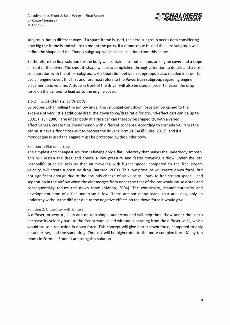
1.5.2 Subsystems 2: Underbody
By properly channelling the airflow under the car, significant down force can be gained to the
expense of very little additional drag; the down force/drag ratio for ground-effect cars can be up to
300:1 (Faul, 1980). The under body of a race car can thereby be shaped to, with a varied
effectiveness, create this phenomenon with different concepts. According to Formula SAE rules the
car must have a floor close-out to protect the driver (Formula SAE® Rules, 2012), and if a
monocoque is used the engine must be protected by the under body.
Solution 1: Flat undertray
The simplest and cheapest solution is having only a flat undertray that makes the underbody smooth.
This will lessen the drag and create a low pressure and faster traveling airflow under the car.
Bernoulli’s p i iple tells us that ai t a eli g ith highe speed, o pa ed to the f ee st ea velocity, will create a pressure drop (Barnard, 2001). This low pressure will create down force, but
not significant enough due to the abruptly change of air velocity – back to free stream speed – and
separation in the airflow when the air emerges from under the rear of the car would cause a stall and
consequentially reduce the down force (Mahon, 2004). The complexity, manufacturability and
development time of a flat undertray is low. There are not many teams that are using only an
undertray without the diffuser due to the negative effects on the down force it would give.
Solution 2: Undertray with diffuser
A diffuser, or venturi, is an add-on to a simple undertray and will help the airflow under the car to
decrease its velocity back to the free stream speed without separating from the diffuser walls, which
would cause a reduction in down force. This concept will give better down force, compared to only
an undertray, and the same drag. The cost will be higher due to the more complex form. Many top
teams in Formula Student are using this solution.

Aerodynamics-Front & Rear Wings - Final Report
by Mikael Sedlacek
2013-09-08
11
Figure 2: Undertray and Diffuser setup
Solution 3: Airdams
Air dams are used in the front of the car to reduce the pressure on the under body of the vehicle, and
at the same time increase the down force. When the car is in motion the lower front of the car is
creating a low pressure zone and by adding air dams the airflow is restricted locally and the airflow
will be accelerated. This will increase the down force, but towards the rear of the car air is flowing in
through the sides and reduces the down force. None of the benchmarked teams are using this
solution.
Figure 3: The effect of an Airdam (Barnard, 2001)
1.5.2.1 Discussion and Final solution(s) 2
In the Pugh matrices the reference for the under body was CFS12 with an undertray and small
diffuser. Air dams are a good add-on but may interfere with other aerodynamic. The winning
concepts were a big and effective diffuser that could, without separating the airflow, de-accelerate
the airflow back to free stream speed. Through these studies and through extensive discussions
within the subgroup and to alumnae we have decided to go for an undertray with diffusers.
The negative effects with this concept are the cost, manufacturability and development time. It will
be more complex and harder to simulate, but considering the benefits and the ratio of down
force/drag that can be gained, this area is important to analyse and give a lot of consideration.
Aerodynamics-Front & Rear Wings - Final Report
by Mikael Sedlacek
2013-09-08
12
1.5.3 Subsystems 3: Cooling
When benchmarking Formula Student cars three main solutions regarding cooling were observed; (1)
A radiator without something to direct the air (2) A single sidepod with a duct used to direct the air
(3) Two sidepods, either one or both used for a duct. The most common solution within the top 20
teams at FS 2012 and FSG 2012 were two sidepods.
The goal is to build a reliable car that can perform well on the track. This requires the engine to run
at its best performance at all times, which consecutively requires that the radiator always provides
enough capacity. For the radiator to work efficiently it demands sufficient air flow through the heat
exchangers. In order to get enough flow through the radiator, it is therefore important to review the
lo atio of the ai i let a d the ae od a i effe ts. The adiato ’s apa it depe ds la gel o the air flow passing through and thereby the mass flow rate is the important factor. Studies show that a
properly designed duct can provide 154% better mass flow rate compared to a simple baseline
shape, and a duct is also said to provide better mass flow compared with drag ratio. Additionally, a
more effective duct will need smaller heat exchangers and can thereby reduce both drag and weight.
This in itself can lead to reduced fuel consumption and hopefully also to faster lap times.
(Christoffersen, 2008)
Since the power train subgroup has specified that they most likely will use one radiator it was
decided to benchmark two alternatives; one single sidepod or two sidepods.
Solution 1: One sidepod
In order to fulfill the need for cooling and based on the fact that the car only will requires one
radiator, only one sidepod is needed. The solution with one sidepod has the advantage that it is
a light alternative and moreover it requires less resources in terms of manufacturing time,
materials and money.
Solution 2: Two sidepods
The solution with two sidepods gives the opportunity to use the one not needed for cooling as
packaging. This sidepod could be used either for the exhaust, electronic or other equipment,
something that the future will show. Further on two sidepods will make the car symmetric which will
have benefits regarding aerodynamics. Last but not least a car with two sidepods is more aesthetic
attractive.
1.5.3.1 Discussion and Final solution(s) 3
There are a few things that are vital to consider when discussing one or two sidepods; aerodynamics,
weight and adjustability. The weight of one sidepod is quite small compared to the overall weight of
the car. The impact on aerodynamics that one sidepod and a non-symmetric car have is hard to
calculate, but it could lead to sideforces acting on the car. A Sidepod can have a streamlined shape
that will direct the air flow in a way so that the drag from the wheel will be reduced. Effects
regarding downforce and the cars behaviour when cornering could also be affected by a non-
symmetric car. Considering the alternatives the benefits of two sidepods will be clearly higher than
the expected negative effects.
Aerodynamics-Front & Rear Wings - Final Report
by Mikael Sedlacek
2013-09-08
13
1.5.4 Subsystems 4: Wings
Wings are not necessary for running a Formula Student car but can be used to increase down force.
Wings are commonly used in Formula 1 and some of the teams competing in the Formula Student
competitions are using wings. The idea with the wings is to reduce pressure at the lower surface of
the wing. The pressure difference between the upper and lower surfaces will give the wing negative
lift (down force) that increases the grip between the road and the tire. The increased grip will
increase the performance when cornering and the car can go with a higher velocity in the corners.
There are some important parameters when evaluation the best solutions:
Solution 1: No wings
One simple solution is to not use wings. Wings will increase the drag on the car and the maximum
velocity for the car will decrease. The no wings solution is commonly used by other teams in the
Formula Student competitions. The CFS11 team and also Delft University of Technology, that finished
second after CFS12 team in FS12, used this solution in their cars.
Solution 2: Front wing
A front wing will increase the down force on the front wheel. No benchmarked cars did use this
solution.
Solution 3: Rear wing
A rear wing will increase the down force on the rear wheel. No benchmarked cars did use this
solution.
Solution 4: Front and rear wing
A wing in the front and rear will increase the down force both in front and rear. This solution was
used by the FS12 CFS12 and also Monash University that finished third in the same competition used
this solution.
1.5.4.1 Discussion and Final solution(s) 4
The t o solutio s f o t i g a d ea i g a gi e a ad fo e dist i utio to the a hi h a make the car behave strange and unpredictable. The car will be over steered or under steered and
these properties will vary with the velocity of the car. The two other solutions are both common in
Formula Student competitions. Both solutions have pro and cons, for example the no wing solution
will have less drag which leads to a higher speed at straight line driving and lower fuel consumption
than for a car with wings. A car with wings will have more down force that will increase the possible
velocity when cornering.
Which solution that is the best depends on the events at the competitions. Some investigations had
been made to find out the advantages and disadvantages with wings. A SAE report called
Aerodynamics for Formula SAE: Initial design and performance prediction (2006) from the Monash
University was studied. The report investigated how wings on the Monash 2003 car would affect the
results in the different dynamic events in Formula Student competitions. The results of the different
events were compared with simulations in the software OptimumLap that were made by the CFS13
Suspension subgroup. The Aero subgroup has summarized the result and calculated that a car with
wings can gain approximately 130 (129.17) points in the competitions compared to a non-winged car.
How these calculatio s e e ade a e ead i Co petitio s “ o es Ae o s No Ae o i the
Aerodynamics-Front & Rear Wings - Final Report
by Mikael Sedlacek
2013-09-08
14
Appendix. A conclusion from the report showed that an aero package that can provide much down
force will gain more points at a Formula Student competition. Also the result from the Pugh matrix,
hi h a e see i the appe di , sho s that the solutio f o t a d ea i g is the est solutio .
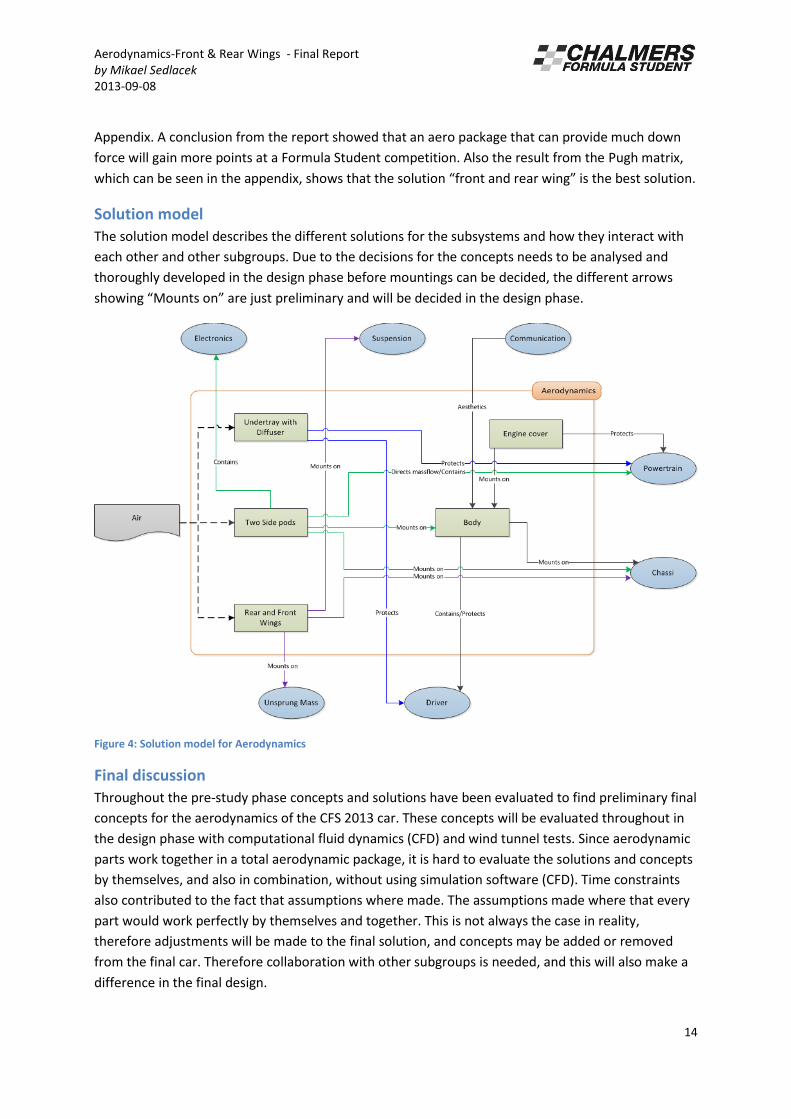
Solution model
The solution model describes the different solutions for the subsystems and how they interact with
each other and other subgroups. Due to the decisions for the concepts needs to be analysed and
thoroughly developed in the design phase before mountings can be decided, the different arrows
sho i g Mou ts o a e just p eli i a a d ill e de ided i the desig phase.
Figure 4: Solution model for Aerodynamics
Final discussion
Throughout the pre-study phase concepts and solutions have been evaluated to find preliminary final
concepts for the aerodynamics of the CFS 2013 car. These concepts will be evaluated throughout in
the design phase with computational fluid dynamics (CFD) and wind tunnel tests. Since aerodynamic
parts work together in a total aerodynamic package, it is hard to evaluate the solutions and concepts
by themselves, and also in combination, without using simulation software (CFD). Time constraints
also contributed to the fact that assumptions where made. The assumptions made where that every
part would work perfectly by themselves and together. This is not always the case in reality,
therefore adjustments will be made to the final solution, and concepts may be added or removed
from the final car. Therefore collaboration with other subgroups is needed, and this will also make a
difference in the final design.

Aerodynamics-Front & Rear Wings - Final Report
by Mikael Sedlacek
2013-09-08
15
Figure 5: This is a sketch made to illustrate the concepts evaluated during the pre-study phase. The sketch is not at all a
final design.
Aerodynamics-Front & Rear Wings - Final Report
by Mikael Sedlacek
2013-09-08
16
2. Design
Hereby a briefing of the design part of the project can be found.
Technical Background
As stated in the problem definition of the pre study part (1.1) the main responsibilities of the
aerodynamic subgroup is to generate down force, reduce drag and generate cooling for the engine.
The parts referred to here are all connected to these three responsibilities. The pre study part also
explains what could be used in order to achieve high down force, low drag and cooling for the
engine. However it does not explain technically how the parts work in order to achieve this.
Therefore a short summary of the physics behind each part will be found beneath.
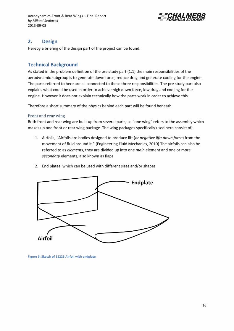
Front and rear wing
Both front and rear wing are built up from several parts; so o e i g refers to the assembly which
makes up one front or rear wing package. The wing packages specifically used here consist of;
1. Ai foils; Airfoils are bodies designed to produce lift (or negative lift: down force) from the
o e e t of fluid a ou d it. E gi ee i g Fluid Me ha i s, The airfoils can also be
referred to as elements, they are divided up into one main element and one or more
secondary elements, also known as flaps
2. End plates; which can be used with different sizes and/or shapes
Figure 6: Sketch of S1223 Airfoil with endplate

Aerodynamics-Front & Rear Wings - Final Report
by Mikael Sedlacek
2013-09-08
17
As stated in the pre study part the wings generate a downwards force by a pressure difference; this
pressure difference comes from the top and lower surface of the airfoils used. To understand why
such pressure difference creates down force one must first understand;
1. Pressure
2. Ne to ’s se o d la
3. Specific weight
4. Eule ’s e uatio of motion of a fluid 5. The Bernoulli equation
I sho t ou appl Ne to ’s se o d la a d the k o ledge of spe ifi eight in order to reach
Eule ’s e uatio fo otio of a fluid. You the appl Eule ’s e uatio alo g a path line to get
Be oulli’s e uatio . If ou egle t is ous effe ts i Be oulli’s e uatio the su ill al a s e
constant along a streamline.
This means that if the flow velocity decreases the static pressure increases; on a race car wing the air
flows faster on the lower surface then on the upper. This results in down force, also known as . The
down force can be calculated through the equation where * is the coefficient of lift,
is the fluid density, is the free-stream velocity measured relative to the body and is the reference
area to the body.
Figure 7: Simplified figure of how an airfoil works
*However to gain more knowledge about all the reasons why specific airfoils generate different amounts of lift (or negative
lift) one must understand the Concept of circulation ∮ . Which combined with ideal flow theory and the Kutta

Aerodynamics-Front & Rear Wings - Final Report
by Mikael Sedlacek
2013-09-08
18
condition will give theoretical lift for indefinitely long airfoils at a small angle of attack. is in this case given by
, where is the angle of attack. (Engineering Fluid Mechanics, 2010)
Drag force, , is given by the equation: . The equation has the same properties as the
equation for down force, however is usually found by experiment. The drag force of an airfoil (and
of a total wing package) is important to know for the main reason that one wants to gain down force
with the addition of as little drag as possible. Thus when designing a wing the lift/drag ( ) ratio
is used in order to measure its performance. (Engineering Fluid Mechanics, 2010)
There are some terminology concerning airfoils that is important to know in order to understand the
differences between airfoils;
Figure 8: Explanation of the key terms of an airfoil
The length of the airfoil is called span, the depth is called chord. Both of the measurements are from
the edges of the airfoil in question. The camber refers to the curvature of the airfoil, it can be
adjusted in order to gain a higher ; what can be used instead or in addition is to increase the angle
of attack However increasing the angle of attack will increase the drag . When the angle of
attack is increased over a certain level the wing will stall; what happens is that the flow separates
from the wing.
Thus in order to gain a good a combination of the correct camber and angle of attack is what
is being sought after.
The leading edge simply refers to the foremost edge of an airfoil section; the trailing edge is the rear
edge of the airfoil section, both are of great importance in order to gain a good and also in
general creating a good airfoil. The trailing edge is of the greatest importance, because you want the
flow to leave the foil smoothly. This can be referred to the Kutta condition and the concept of
circulation. (Engineering Fluid Mechanics, 2010)
Aerodynamics-Front & Rear Wings - Final Report
by Mikael Sedlacek
2013-09-08
19
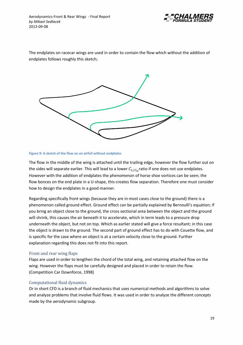
The endplates on racecar wings are used in order to contain the flow which without the addition of
endplates follows roughly this sketch;
Figure 9: A sketch of the flow on an airfoil without endplates
The flow in the middle of the wing is attached until the trailing edge, however the flow further out on
the sides will separate earlier. This will lead to a lower ratio if one does not use endplates.
However with the addition of endplates the phenomenon of horse shoe vortices can be seen; the
flow bonces on the end plate in a U-shape, this creates flow separation. Therefore one must consider
how to design the endplates in a good manner.
Regarding specifically front wings (because they are in most cases close to the ground) there is a
phenomenon called ground effect. Ground effect can be partially explained by Bernoulli’s equation; if
you bring an object close to the ground, the cross sectional area between the object and the ground
will shrink, this causes the air beneath it to accelerate, which in term leads to a pressure drop
underneath the object, but not on top. Which as earlier stated will give a force resultant; in this case
the object is drawn to the ground. The second part of ground effect has to do with Couette flow, and
is specific for the case where an object is at a certain velocity close to the ground. Further
explanation regarding this does not fit into this report.
Front and rear wing flaps
Flaps are used in order to lengthen the chord of the total wing, and retaining attached flow on the
wing. However the flaps must be carefully designed and placed in order to retain the flow.
(Competition Car Downforce, 1998)
Computational fluid dynamics
Or in short CFD is a branch of fluid mechanics that uses numerical methods and algorithms to solve
and analyze problems that involve fluid flows. It was used in order to analyze the different concepts
made by the aerodynamic subgroup.

Aerodynamics-Front & Rear Wings - Final Report
by Mikael Sedlacek
2013-09-08
20
Computer-aided design
Also known as CAD, is the use of computers to visualize, analyze and optimize designs.
Race car aerodynamics in short; do not let the flow separate or as little as possible, and you will be
successful.
Team goal in reference
The team goal states;
In order to become outstanding Engineers with professional experience, we will, as a team, through
data driven decisions and efficient engineering, design and deliver a reliable yet lightweight Formula
Racing Solution to achieve 900 points at FS13.
The subgroup goal states;
In order to become outstanding engineers, we will, as a subgroup, through data driven decisions,
gain experience by designing and delivering an adjustable and reliable yet lightweight efficient
aerodynamic solution to achieve 900 points at FS13.
Aerodynamics-Front & Rear Wings - Final Report
by Mikael Sedlacek
2013-09-08
21
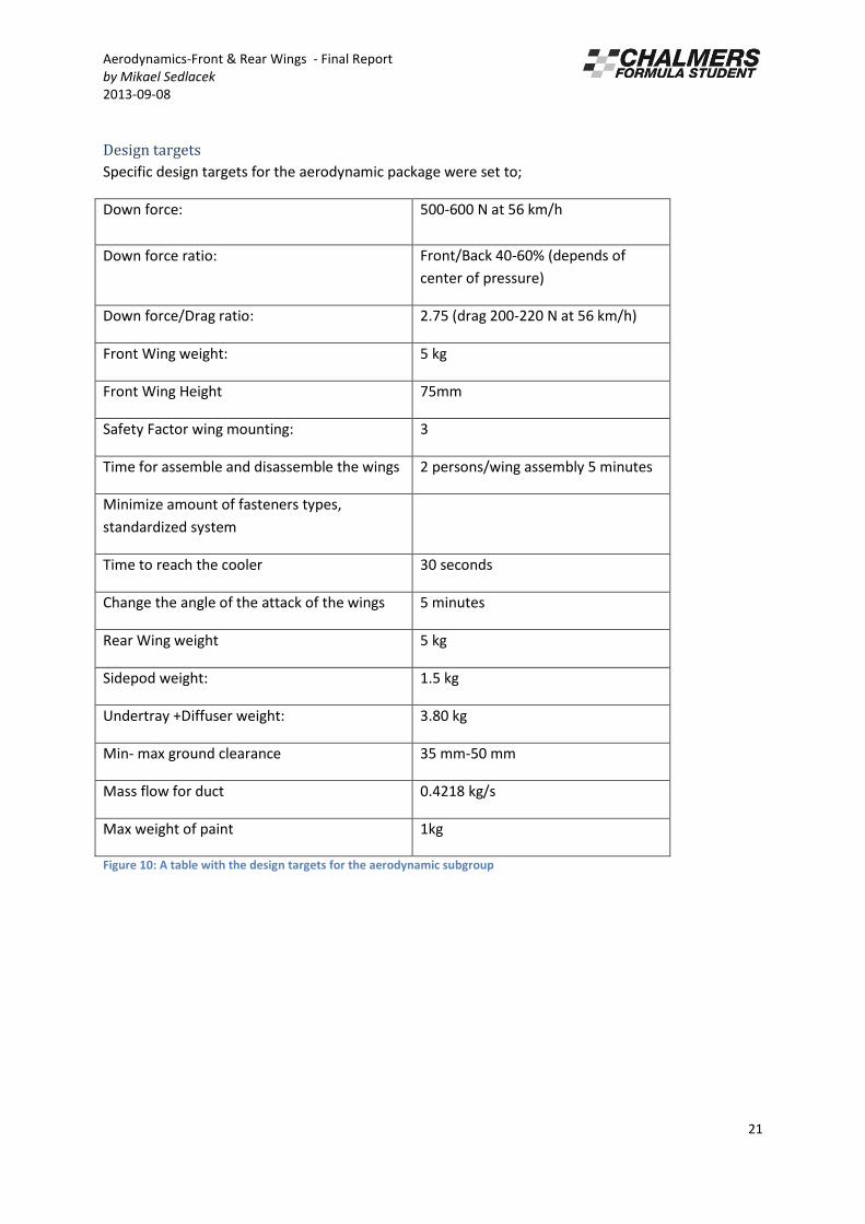
Design targets
Specific design targets for the aerodynamic package were set to;
Down force: 500-600 N at 56 km/h
Down force ratio: Front/Back 40-60% (depends of
center of pressure)
Down force/Drag ratio: 2.75 (drag 200-220 N at 56 km/h)
Front Wing weight: 5 kg
Front Wing Height 75mm
Safety Factor wing mounting: 3
Time for assemble and disassemble the wings 2 persons/wing assembly 5 minutes
Minimize amount of fasteners types,
standardized system
Time to reach the cooler 30 seconds
Change the angle of the attack of the wings 5 minutes
Rear Wing weight 5 kg
Sidepod weight: 1.5 kg
Undertray +Diffuser weight: 3.80 kg
Min- max ground clearance 35 mm-50 mm
Mass flow for duct 0.4218 kg/s
Max weight of paint 1kg
Figure 10: A table with the design targets for the aerodynamic subgroup
Aerodynamics-Front & Rear Wings - Final Report
by Mikael Sedlacek
2013-09-08
22
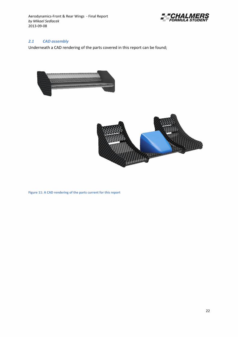
2.1 CAD assembly
Underneath a CAD rendering of the parts covered in this report can be found;
Figure 11: A CAD rendering of the parts current for this report
Aerodynamics-Front & Rear Wings - Final Report
by Mikael Sedlacek
2013-09-08
23
2.2 Front wing
2.2.1 Design choice/ selection
The front wing is made up from: endplates, main elements, flaps and a middle segment. Underneath
a brief explanation of each sub part is given. The final total weight of the front wing is 2500 grams
without the mounts.
Airfoils
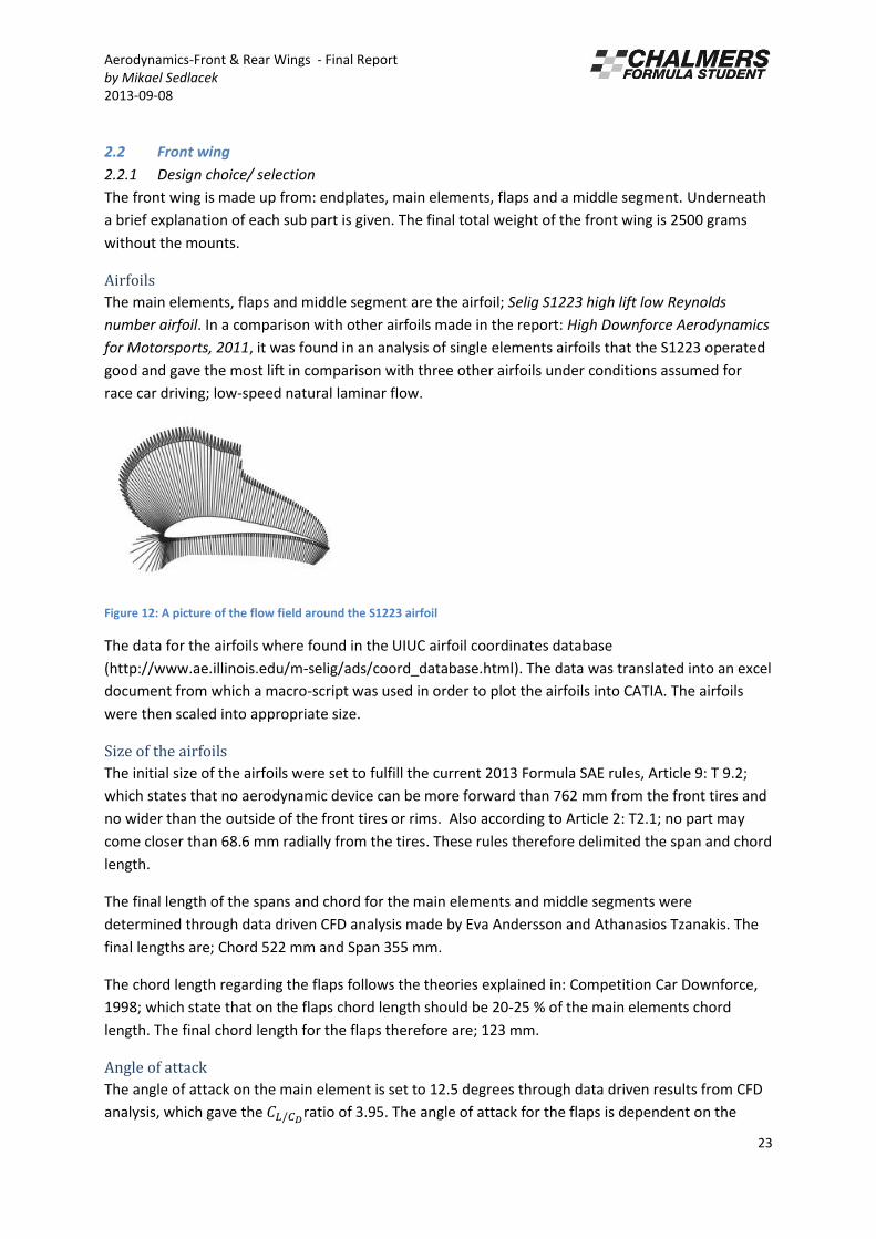
The main elements, flaps and middle segment are the airfoil; Selig S1223 high lift low Reynolds
number airfoil. In a comparison with other airfoils made in the report: High Downforce Aerodynamics
for Motorsports, 2011, it was found in an analysis of single elements airfoils that the S1223 operated
good and gave the most lift in comparison with three other airfoils under conditions assumed for
race car driving; low-speed natural laminar flow.
Figure 12: A picture of the flow field around the S1223 airfoil
The data for the airfoils where found in the UIUC airfoil coordinates database
(http://www.ae.illinois.edu/m-selig/ads/coord_database.html). The data was translated into an excel
document from which a macro-script was used in order to plot the airfoils into CATIA. The airfoils
were then scaled into appropriate size.
Size of the airfoils
The initial size of the airfoils were set to fulfill the current 2013 Formula SAE rules, Article 9: T 9.2;
which states that no aerodynamic device can be more forward than 762 mm from the front tires and
no wider than the outside of the front tires or rims. Also according to Article 2: T2.1; no part may
come closer than 68.6 mm radially from the tires. These rules therefore delimited the span and chord
length.
The final length of the spans and chord for the main elements and middle segments were
determined through data driven CFD analysis made by Eva Andersson and Athanasios Tzanakis. The
final lengths are; Chord 522 mm and Span 355 mm.
The chord length regarding the flaps follows the theories explained in: Competition Car Downforce,
1998; which state that on the flaps chord length should be 20-25 % of the main elements chord
length. The final chord length for the flaps therefore are; 123 mm.
Angle of attack
The angle of attack on the main element is set to 12.5 degrees through data driven results from CFD
analysis, which gave the ratio of 3.95. The angle of attack for the flaps is dependent on the
Aerodynamics-Front & Rear Wings - Final Report
by Mikael Sedlacek
2013-09-08
24
angle of attack of the main element, the angle is set to 12.5 degrees in relation to the chord axle; it
can also later be adjusted on the car in order to fine tune the down force gained from the front wing
package. However neither the main element nor the middle segment can be adjusted later.
The middle segments angle of attack was set to 0 degrees because of the symbiosis between side
pods, diffuser and wings, explained in the discussion section below.
Ground clearance
The ground clearance of the wing package was set to 75 mm because of the 2013 Formula SAE rules
regarding jacking of the car: Article 6, T6.6.2 and the rules stating that no part of the car may touch
the ground during competition Article 6, T6.2. Part of the limitations is also the cars suspension
system, and specifically pitch; however the jacking rules was the most limiting.
End plates
The final size of the endplates was set to; length: 638 mm height 339 mm. The size is based partly on
data driven CFD analysis by Eva Andersson and Athanasios Tzanakis. It is also based on earlier stated
rules about both ground clearance and aerodynamic devices.
2.2.2 Discussion of design selection/ Limitations
Beneath a brief explanation of the most important concepts that lead to the final design.
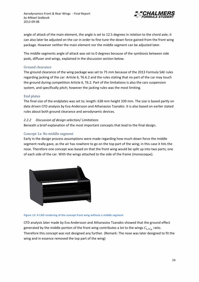
Concept 1a: No middle segment
Early in the design process assumptions were made regarding how much down force the middle
segment really gave, as the air has nowhere to go on the top part of the wing; in this case it hits the
nose. Therefore one concept was based on that the front wing would be split up into two parts; one
of each side of the car. With the wings attached to the side of the frame (monocoque).
Figure 13: A CAD rendering of the concept front wing without a middle segment
CFD analysis later made by Eva Andersson and Athanasios Tzanakis showed that the ground effect
generated by the middle portion of the front wing contributes a lot to the wings ratio.
Therefore this concept was not designed any further. (Remark: The nose was later designed to fit the
wing and in essence removed the top part of the wing)

Aerodynamics-Front & Rear Wings - Final Report
by Mikael Sedlacek
2013-09-08
25
Concept 1b: Neutral middle
This concept was made with the thought that since ground effect had an effect on the wing s
ratio; but nothing was to be gained on top of the wing (since the air was blocked by the nose) it
would be easy to manufacture a wing with a simple segment in the middle; also the fact that a bigger
area of the wing would be close to the ground (bigger ground effect) was part of the thought behind
this concept. Also part of the thought is that air needs to go in-between the endplates and chassis in
order to reach the side pod inlet; if you have an airfoil at a steep angle of attack in the middle
segment, it could possibly make the air flow over the inlet.
CFD analysis later made by Eva Andersson and Athanasios Tzanakis showed that turbulent flow was
created by the neutral middles shape and the gains from ground effect where not as big as expected.
Therefore this concept was not used as it was first intended;
Figure 14: A CAD rendering of the concept with a neutral middle segment
Because of this it was tested to use an airfoil with 0 degrees in angle of attack in the middle, and the
main segments at a different angle; this proved to be the best design. It can be seen in the final front
wing design.
Concept 2a: Different sized end plates
Because of the effects end plates can have on airfoils(earlier explained), the thought that small
endplates in the middle part of the wing would contribute to a better, or unchanged ratio.
Since the flow theoretically is attached in the middle part of the wing.

Aerodynamics-Front & Rear Wings - Final Report
by Mikael Sedlacek
2013-09-08
26
Figure 15: A CAD rendering of the concept with small end plates
However CFD analysis later showed that the ratio decreased with smaller endplates.
Concept 2b: End plates at different distances from the chassis
As with the neutral middle concepts, this concept partly had to do with getting flow to the inlet of
the side pod. CFD analysis by Eva Andersson, Athanasios Tzanakis, with different iterations of the end
plates placed at different distances from the chassis, later gave a compromise in which the inlet
receives enough flow and the front wing has a good enough ratio.
Figure 16: A CAD rendering of the concept with endplates close to the chassis
2.2.3 Simulations/ Tests/ Experiments
The used software to realize sketches into CAD was Dassault Systems CATIA v5 r19. This CAD was
then cleaned and meshed in the program Ansa 13.2.3. To finally do the CFD analysis the program CD-
Adapco Star CCM + 7.4 was used.
Aerodynamics-Front & Rear Wings - Final Report
by Mikael Sedlacek
2013-09-08
27
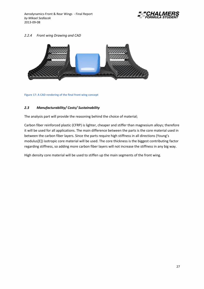
2.2.4 Front wing Drawing and CAD
Figure 17: A CAD rendering of the final front wing concept
2.3 Manufacturability/ Costs/ Sustainability
The analysis part will provide the reasoning behind the choice of material;
Carbon fiber reinforced plastic (CFRP) is lighter, cheaper and stiffer than magnesium alloys; therefore
it will be used for all applications. The main difference between the parts is the core material used in
et ee the a o fi e la e s. “i e the pa ts e ui e high stiff ess i all di e tio s You g’s modulus[E]) isotropic core material will be used. The core thickness is the biggest contributing factor
regarding stiffness, so adding more carbon fiber layers will not increase the stiffness in any big way.
High density core material will be used to stiffen up the main segments of the front wing.

Aerodynamics-Front & Rear Wings - Final Report
by Mikael Sedlacek
2013-09-08
28
2.4 Rear wing
2.4.1 Design choice/ selection
The front wing is made up from: endplates, one main element, two flaps.
Underneath a brief explanation of each sub part is given. The final total weight of the rear wing is
2660 grams.
Airfoils and their size
The same airfoils and theory surrounding the same was used for the rear wing as with the front wing.
However two flaps were used instead of one; there are several reasons for the difference: there is
more room in the back of the car, the rear wing does not benefit from ground effect and there is no
side pod inlet that needs to be considered.
The initial size of the main segment chord size was based partly around the 2013 Formula SAE rules,
Article 9, T9.2, which states that no aerodynamic device may be further rearwards than 305 mm
from the rear wheels and partly on the rear sub frames dimensions. The span is based on the
wheelbase because of the same rules as with the front wing.
Later CFD analysis by Eva Andersson, Athanasios Tzanakis gave the final sizes of the main segments
chord. Main segments chord: 515 mm, span 1390 mm. The flaps have the same span as the main
segment, and a chord length of: 125 mm. This chord length follows the same theory as explained
with the front wing flaps (the chords are 24 % of the main segments chord).
Angle of attack
The angle of attack on the main element is set to 7.5 degrees through data driven results from CFD
analysis which gave a ratio of 3.47. The angle of attack can be adjusted for both flaps, the flap
closest to the main segment has an attack angle of 7.5 degrees in relation the main segments chord
axle and the second flap has the same relationship with the first flaps chord axle.
The angle of attack increased the from the initial 1.72 with 0 angle of attack to 3.47.
End plates
The final size of the endplates was set to; length: 700 mm height 450 mm. The size is based partly on
data driven CFD analysis by Eva Andersson, Athanasios Tzanakis. It is also based on earlier stated
rules about aerodynamic devices.
2.4.2 Discussion of design selection/ Limitations
Beneath a brief explanation of the most important concepts that lead to the final design can be
found.
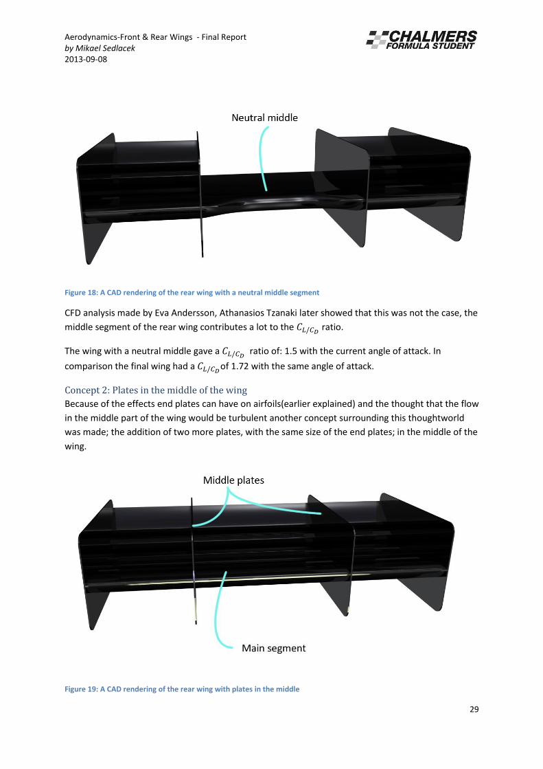
Concept 1: Neutral middle
Early in the design process assumptions were made regarding how much down force the middle
segment really could give, since there was an assumption that the roll hoop would create turbulent
flow in the middle part of the wing; and thus lead to un-attached flow. Therefore concept one was
based on a wing with four end plates and a neutral middle;
Aerodynamics-Front & Rear Wings - Final Report
by Mikael Sedlacek
2013-09-08
29
Figure 18: A CAD rendering of the rear wing with a neutral middle segment
CFD analysis made by Eva Andersson, Athanasios Tzanaki later showed that this was not the case, the
middle segment of the rear wing contributes a lot to the ratio.
The wing with a neutral middle gave a ratio of: 1.5 with the current angle of attack. In
comparison the final wing had a of 1.72 with the same angle of attack.
Concept 2: Plates in the middle of the wing
Because of the effects end plates can have on airfoils(earlier explained) and the thought that the flow
in the middle part of the wing would be turbulent another concept surrounding this thoughtworld
was made; the addition of two more plates, with the same size of the end plates; in the middle of the
wing.
Figure 19: A CAD rendering of the rear wing with plates in the middle
Aerodynamics-Front & Rear Wings - Final Report
by Mikael Sedlacek
2013-09-08
30
However CFD analysis by Eva Andersson, Athanasios Tzanaki showed that the wing had a ratio
of 1.68, with the current angle of attack. Which is worse in comparison with the final wing at the
same angle of attack (1.72). Another factor affecting is that adding plates in the middle adds weight,
and at a bad place in the car dynamically (it is placed high up, far away from the center of the car).
2.4.3 Simulations/ Tests/ Experiments
The used software to realize sketches into CAD was Dassault Systems CATIA v5 r19. This CAD was
then cleaned and meshed in the program Ansa 13.2.3. To finally do the CFD analysis the program CD-
Adapco Star CCM + 7.4 was used.
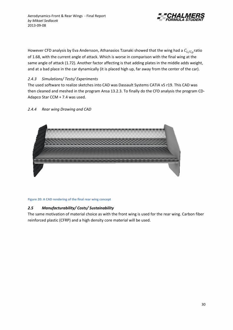
2.4.4 Rear wing Drawing and CAD
Figure 20: A CAD rendering of the final rear wing concept
2.5 Manufacturability/ Costs/ Sustainability
The same motivation of material choice as with the front wing is used for the rear wing. Carbon fiber
reinforced plastic (CFRP) and a high density core material will be used.

Aerodynamics-Front & Rear Wings - Final Report
by Mikael Sedlacek
2013-09-08
31
Analysis
Hereby the analysis part of the project can be found.
Material selection for the wings
Hereby a briefing on how the material for the wings where chosen can be found.
2.6 Software tools
Granata design, Cambridge Material Selector.
Learned through the course MTT075 Material och processval (Material and process selection).
2.7 Simulation stages/ steps and parameters
The following factors where used in order to delimit the materials to only the ones that fulfills the
primal needs for the wings:
1. Function
- Improve (decrease) drag coefficient
- Provide down force
- Be hit by small debris without cracking
2. Demands
- Be able to manufacture in the shape of current CAD model
- Total weight of one < 0.6 kg
- You g’s odulus > GPa
- Fracture toughness KIC 1 Mpa.m^0.5
- Be able to drop from 1 m
3. Goal function
Minimize weight (density), price,
Ma i ize ou g’s odulus/de sit E/δ
4. Free variables
Choice of material

Aerodynamics-Front & Rear Wings - Final Report
by Mikael Sedlacek
2013-09-08
32
2.8 Results
Figure 21: A graph with aterials with you g’s odulus plotted agai st de sity
The g aph sho s You g’s odulus plotted agai st De sit fo all the ate ials fulfilling the earlier
stated factors. Two materials were found to fulfill these; Carbon fiber reinforced plastic (CFRP) and
magnesium alloys.
2.9 Recommendation
In order to use the program successfully one must first clearly define goal functions, which in all
cases will not be as simple as Ma i ize ou g’s odulus/de sit ; the goal function is most often
what one wants to display in the graph. Another important factor is to clearly define factual
de a ds; i this ase the de a ds he e so high ega di g ou g’s odulus and density that only
two material fit in; most often this will not be the case, especially if one looks for cheap plastics. In
the case that a lot of materials are found; the factors should be that for instance if one wants a
material with high young’s odulus a d lo de sit , the ou g’s odulus pa t of the plot should e i e ted. This a the ate ials ith the est ou g’s odulus/de sit ill e displa ed to the left of the graph. Any of these materials can be chosen for the application.
Aerodynamics-Front & Rear Wings - Final Report
by Mikael Sedlacek
2013-09-08
33
CFD
Hereby a short briefing on the Computational fluid dynamics made by Eva Andersson and Athanasios
Tzanakis for the wings can be found.
2.10 Software tools
The software used for the CFD analysis was first Ansa 13.2.3 to clean the CAD up, create the mesh
and to create the wind tunnel. After this CD-Adapco Star CCM + 7.4 was used for the analysis itself.
The steps behind the process can be found in Eva Andersson and Athanasios Tzanakis reports.
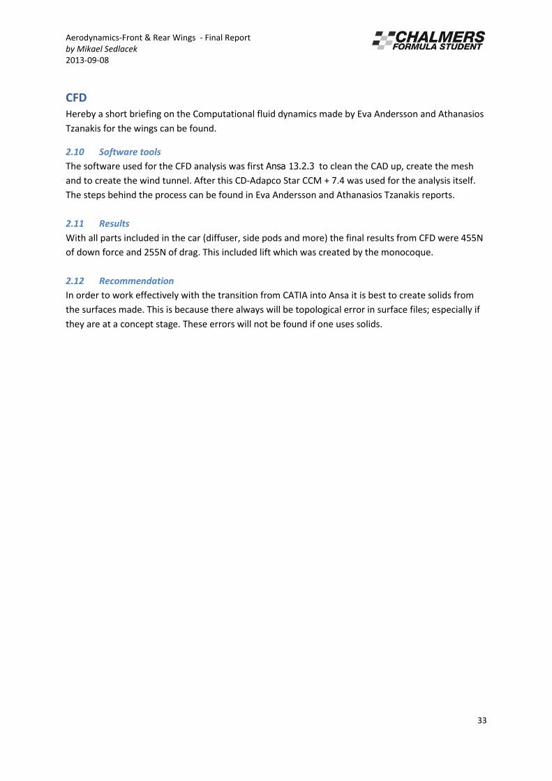
2.11 Results
With all parts included in the car (diffuser, side pods and more) the final results from CFD were 455N
of down force and 255N of drag. This included lift which was created by the monocoque.
2.12 Recommendation
In order to work effectively with the transition from CATIA into Ansa it is best to create solids from
the surfaces made. This is because there always will be topological error in surface files; especially if
they are at a concept stage. These errors will not be found if one uses solids.

Aerodynamics-Front & Rear Wings - Final Report
by Mikael Sedlacek
2013-09-08
34
3. Manufacturing
Following the earlier established data considering material properties the material chosen for front
and rear wing were carbon fiber reinforced plastic (CFRP). However there are first of all many
different types of Carbon fiber weaves, with different properties such as weight and stiffness in
different directions. Second of all to get a lightweight yet stiff CFRP part a core material had to be
used. Adding to this there are many types of CFRP manufacturing methods that could be used. All of
which were established through both availability of material and what gives the best results.
Underneath you will find which type of weave, manufacturing method and core material where used
for the parts and why they were chosen.
The parts are split up in; molds, front wing main, rear wing main, flaps and endplates.
3.1 Molds
One thing that were established, with only the prior knowledge that CFRP were to be used; molds
would have to be manufactured. Now as with CRFP, different types of material and methods for
creating a mold could be used. In short terms the higher the density of the material used, the higher
the finish of the final product would be. For the wings the finish is of upmost importance, since lower
skin friction means more attached flow. Considering the time constraints and high quality demands,
the method for creating the molds, Computer Numerically controlled (CNC) mill, combined with
limited manual work were chosen.
Thus the material Ureol were chosen with a density of 400g/l. The decision of using Ureol was in part
because of the availability, since Volvo Concept Centre was providing the material. There were also
concerns from the company providing the Computer Numerically controlled (CNC) mill, Cliff, because
they did not want to use their mills on any mold material, considering work environment factors.
In order for Cliff to mill the molds to specification the molds themselves were CAD:ed from the final
design set. The molds were made for front and rear wing main elements and flaps. These molds
consisted of a top part and bottom part and would later be glued together in order to form the total
airfoil. The mold is made by inverting the parts so that the outside meets the mold surface. This is so
that the surface on the outside gets the best finish and lowest skin friction. When the wing is
inverted a box was CAD:ed around it to determine how much mold material would be used, and how
it should be cut before putting it in the mill. In order to prepare the molds for Cliff the mold material
was cut and glued together in blocks at Cliff:s workshop.
Figure 22 A CAD of the top part of the front wing main element mold
Aerodynamics-Front & Rear Wings - Final Report
by Mikael Sedlacek
2013-09-08
35
After the molds had been milled by Cliff they had to be prepared for a Carbon fiber layup, so that the
surface finish of the final parts could be as good as possible. This was done by first sanding the molds
and then waxing them with car wax for several layers. Now they were ready for layup!
3.2 Manufacturing method used
With the molds at Volvos concept lab (VCC) the layup could begin. As earlier mentioned there are
several ways to manufacture CFRP. The basics of manufacturing CFRP are that you need carbon fiber
cloth, epoxy and a vacuum bag. You can then choose to cure the part in room temperature, with an
oven or an autoclave(a pressurized oven). An autoclave or oven provides better quality and stiffness
of the parts however in the case of the wings it was chosen to cure in room temperature because the
stiffness needed was reached by this method. A vacuum bag is used to compress the cloth and epoxy
while curing so that the cloth does not move or expand.
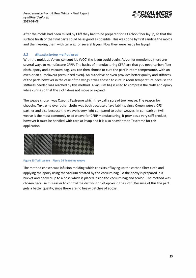
The weave chosen was Oxeons Textreme which they call a spread tow weave. The reason for
choosing Textreme over other cloths was both because of availability, since Oxeon were a CFS
partner and also because the weave is very light compared to other weaves. In comparison twill
weave is the most commonly used weave for CFRP manufacturing, it provides a very stiff product,
however it must be handled with care at layup and it is also heavier than Textreme for this
application.
Figure 23 Twill weave Figure 24 Textreme weave
The method chosen was infusion molding which consists of laying up the carbon fiber cloth and
applying the epoxy using the vacuum created by the vacuum bag. So the epoxy is prepared in a
bucket and hooked up to a hose which is placed inside the vacuum bag and sealed. The method was
chosen because it is easier to control the distribution of epoxy in the cloth. Because of this the part
gets a better quality, since there are no heavy patches of epoxy.

Aerodynamics-Front & Rear Wings - Final Report
by Mikael Sedlacek
2013-09-08
36
Figure 25 A picture of using vacuum infusion for the top part of the rear wing
As displayed in the picture you can see that a layer of textile is placed on top of the Carbon fiber
cloth. This is so that the vacuum bag does not stick to the cloth. The little green scraper seen in the
picture is used to press out any shrinks made by the vacuum bag so that no deformities are created
by the vacuum bag compressing the carbon fiber. All the wing parts were made using the same
method, however the endplates did not need CNC milled molds since they were flat.
3.3 Front wing airfoils
A brief on how the front wing airfoils were made can be found underneath.
3.3.1 Manufacturing
For the front wing main top element three (3) layers of 200g/m2
Textreme cloth were used. The top
layer(the one seen on the finished product) was placed at 90 degree angle and the two other placed
in 45 degrees compared to the first layer. The layers are placed in this way to get stiffness in several
directions. The front wing main bottom element was made with three (3) layers of 100 g/m2
Textreme cloth, placed in the same manner as for the top element.
To get stiffness in the wing high density core material was CNC milled at the Chalmers workshop. This
was done by using a two dimensional profile of the airfoil. Thirteen (13) ribs were made with a
thickness of 20 mm and then placed out on the top element of the wing using epoxy. To add stiffness

Aerodynamics-Front & Rear Wings - Final Report
by Mikael Sedlacek
2013-09-08
37
in the width direction of the wing supports were hand trimmed in rectangular shapes and placed in
between the ribs.
Figure 26 A picture of the ribs placed out on the top part of the wing
When the core material had been placed the bottom part of the wing was glued together with the
top part of the wing. The flaps were made using the same exact same methods with two (2) layers of
100g/m2 Textreme cloth on both top and bottom elements.
3.3.2 Design changes
No specific design changes were made.
Aerodynamics-Front & Rear Wings - Final Report
by Mikael Sedlacek
2013-09-08
38
3.4 Rear wing airfoils
A brief on how the rear wing airfoils were made can be found underneath.
3.4.1 Manufacturing
For the rear wing main top and bottom elements, three (3) layers of 100g/m2
Textreme cloth were
used. The top layer (the one seen on the finished product) was placed at 90 degree angle and the
two other placed in 45 degrees compared to the first layer. The same method as used with the front
wing with core material and gluing together the top and bottom parts were used for the rear wing.
3.4.2 Design changes
No specific design changes were made.
3.5 Front and rear wing end plates
A brief on how the endplates were made can be found underneath.
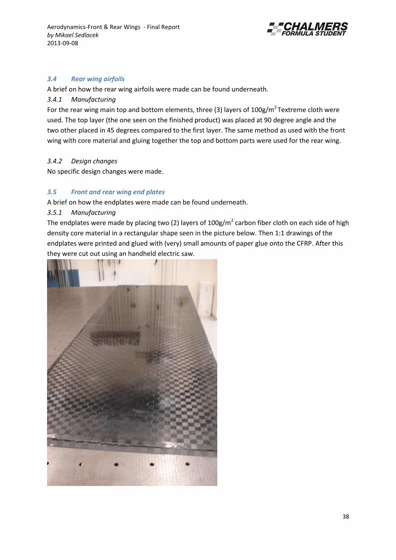
3.5.1 Manufacturing
The endplates were made by placing two (2) layers of 100g/m2 carbon fiber cloth on each side of high
density core material in a rectangular shape seen in the picture below. Then 1:1 drawings of the
endplates were printed and glued with (very) small amounts of paper glue onto the CFRP. After this
they were cut out using an handheld electric saw.
Aerodynamics-Front & Rear Wings - Final Report
by Mikael Sedlacek
2013-09-08
39
3.5.2 Design changes
A lot of design changes were made to the endplates, mainly because the endplates from the
beginning were completely rectangular. This was not optimal from a weight saving point of view, and
looking back at the wing theory presented the flow at the beginning of the airfoil does not have to be
contained with endplates. Testing was done with endplates cut out in aluminum with two different
concepts, and no differences in down force could be seen.

Aerodynamics-Front & Rear Wings - Final Report
by Mikael Sedlacek
2013-09-08
40
4. Manufacturing coordination
The writer of this report was manufacturing coordinator during the manufacturing phase of the
project. Since a lot was learned during this period, and the setup of the Bill of material (BOM) and
overall planning were important and time consuming parts it was figured that something had to be
written about it, so that the knowledge can be transferred to CFS 14. To motivate the improvements
proposed a short brief on how the BOM and planning was handled during CFS 13 will be found
underneath.
4.1.1 Bill of material and overall planning
Coming back from Christmas holiday two meetings were held in which a time schedule was set up
with each subgroup specifying when certain subsystems should be manufactured. From this the
subgroups then set up the BOM specific for their parts, and put a specific date to each part that was
going to match the time schedule set up for the subsystem. The Bill of material was set up by each
subgroup using an Excel template document, with each parameter set up prior by the manufacturing
coordinator.
Figure 27 Picture of a part of the BOM initially set up
(Considering the amount of parameters all of them are not mentioned in this report, templates can
be found in the manufacturing folder for CFS 13.)
Aerodynamics-Front & Rear Wings - Final Report
by Mikael Sedlacek
2013-09-08
41
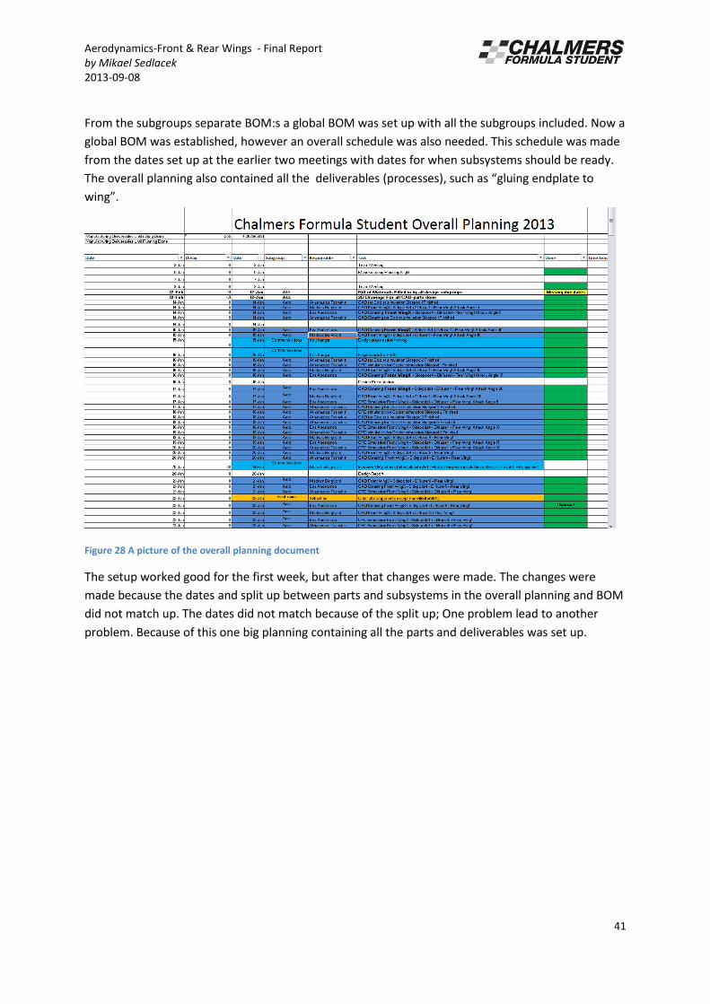
From the subgroups separate BOM:s a global BOM was set up with all the subgroups included. Now a
global BOM was established, however an overall schedule was also needed. This schedule was made
from the dates set up at the earlier two meetings with dates for when subsystems should be ready.
The overall planning also contained all the deliverables (processes), such as gluing endplate to
wing .
Figure 28 A picture of the overall planning document
The setup worked good for the first week, but after that changes were made. The changes were
made because the dates and split up between parts and subsystems in the overall planning and BOM
did not match up. The dates did not match because of the split up; One problem lead to another
problem. Because of this one big planning containing all the parts and deliverables was set up.
Aerodynamics-Front & Rear Wings - Final Report
by Mikael Sedlacek
2013-09-08
42
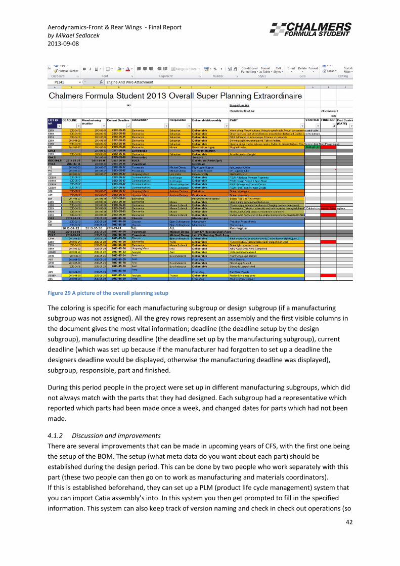
Figure 29 A picture of the overall planning setup
The coloring is specific for each manufacturing subgroup or design subgroup (if a manufacturing
subgroup was not assigned). All the grey rows represent an assembly and the first visible columns in
the document gives the most vital information; deadline (the deadline setup by the design
subgroup), manufacturing deadline (the deadline set up by the manufacturing subgroup), current
deadline (which was set up because if the manufacturer had forgotten to set up a deadline the
designers deadline would be displayed, otherwise the manufacturing deadline was displayed),
subgroup, responsible, part and finished.
During this period people in the project were set up in different manufacturing subgroups, which did
not always match with the parts that they had designed. Each subgroup had a representative which
reported which parts had been made once a week, and changed dates for parts which had not been
made.
4.1.2 Discussion and improvements
There are several improvements that can be made in upcoming years of CFS, with the first one being
the setup of the BOM. The setup (what meta data do you want about each part) should be
established during the design period. This can be done by two people who work separately with this
part (these two people can then go on to work as manufacturing and materials coordinators).
If this is established beforehand, they can set up a PLM (product life cycle management) system that
you can import Catia asse l ’s into. In this system you then get prompted to fill in the specified
information. This system can also keep track of version naming and check in check out operations (so
Aerodynamics-Front & Rear Wings - Final Report
by Mikael Sedlacek
2013-09-08
43
that you don’t screw up CAD files). All the KBE (knowledge based engineering) data can also be saved
within this system, such as simulations and Matlab scripts. In this case you would have all the
information at the same place. Adding to this you can create views within the system and add
users to it. A view means showing specific information to that specific user. Thus you only get the
information you need to know, avoiding information overflow. The manufacturer can then release
the file within the system and thus it is marked as done. Making the work of meeting each week to
establish which parts are done obsolete. This system already exists in the form of Dassault systems
Smarteam, which Chalmers has a license for.
One main problem with the setup used for CFS 13 was that it was hard to get an overview of the total
progress. This was due to information overflow in the overall document. It was not easy to see which
part lead to the next. But if the system mentioned above is setup a lot more time can be spent on
looking at the overall progress, and thus having an overall planning.
Another problem was that the designers did not manufacture their own parts, this lead to confusion
and loss of motivation. It was clear that if the designers had made their own parts they would have
been more motivated to finish their assembly. It would also simplify planning enormously, if one
designer has a set of parts that have to be done he or she can plan their own work accordingly. In the
setup used by CFS 13 the subgroup representative gave out responsibilities and planned the work for
the subgroup, which lead to that the parts were being made in a too random order. It would have
been beneficial to finish one assembly at a time.

Aerodynamics-Front & Rear Wings - Final Report
by Mikael Sedlacek
2013-09-08
44
5. Costs
The selection of processes, design and manufacturing were considered for cost in the sense that first
of all the only really viable material for wings were CFRP, which was established in the material
selection process. Second of all top teams competing were using CFRP for their wings and thus it
would not affect CFS negatively compared to other teams.
Now of course using the motivation everybody uses it is never good, however as stated this was
considering competing against other teams in cost event only. In which it is a factor which material is
being used by other teams.
6. Testing/ Validation
Only dynamic testing was performed as no static tests were needed for the wings.
6.1 Dynamic testing
Dynamic testing was performed to evaluate which endplate design was going to be used and testing
different flap attack angles.
6.1.1 Motivation
The main reason for dynamic testing of the aerodynamic package was to get as good front to rear
down force distribution as possible. For the current car it was more important to think about the
dynamics of the car rather than gaining maximum amount of down force unevenly distributed.
6.1.2 Test setup
Both for testing which endplates were going to be used and setting up the angle of attack for the
flaps potentiometers which measured the damper travel were used. This is used in order to calculate
the down force on the front and rear wheels.
6.1.3 Results
As mentioned earlier two endplate concepts were tested, they had the same basic shape but one
version was smaller in total area. Testing proved that there was no difference between the two
versions and thus the smallest version was chosen considering weight saving.
For the flap settings the angle of attack proved a difference in weight distribution and the angle 12.5
degrees for the front flaps and 7.5 for the rear flaps was the best setup for good down force
distribution if you consider the endurance event. However since there are different events a neutral
angle of attack was used for acceleration, since you do not need down force and rather minimum
amounts of drag in that event (for this car).
Aerodynamics-Front & Rear Wings - Final Report
by Mikael Sedlacek
2013-09-08
45
7. Improvements/ Conclusion/ Recommendation
Because of two members with a lot of prior knowledge about wings quit the project early on the
design of the wings was put on two aero members with little prior knowledge about wings
specifically (however with basic knowledge in fluid mechanics). Since this knowledge had to be read
up a lot of time was spent on this. This also gave less time to spend on designing only the wings since
the writer of this report also was involved with every single subsystem of the Aero subgroup. This in
combination with problems of setting up CFD simulations and CAD cleaning for the same led to a
very unplanned process.
Wings are not easy to design, and definitely not for a race car since the air is very turbulent and
ground effect is in use. Also considering there are no established ways to design wings for a race car,
since the wings differ depending how the car will be put together. Thus the recommendation is to set
one or two people responsible for making the front and rear wing. They should have some prior
knowledge about wings and also about mechanical simulations in Ansys. The problems with CFD and
CAD cleaning can be solved by putting one person responsible for CAD and CFD. This person does not
have to make the CAD for the wings, however should be responsible for the CAD within the
subgroup, so that everyone knows how to work and set up the parts so that they are prepared for
CAD cleaning.
A vital part of selling a product is aesthetics, and very specifically a race car. Aesthetics are one of the
key aspects of a race car that is to be sold to a consumer. CFS approach to aesthetics and branding is
very old fashioned, where the engineering is put before aesthetics. The best product is a combination
of both. Now of course for this specific application, where the car is raced in a competition and not
actually sold makes the engineering part more important.
However in the car industry the aesthetics are often what is made first. That is; industrial designers
makes the initial concept and the car is built to fit within those specifications. Thus it could be a good
idea to introduce another event at the competitions; aesthetical judgment (and branding). Since it is
such a vital part of the industry.

Aerodynamics-Front & Rear Wings - Final Report
by Mikael Sedlacek
2013-09-08
46
8. References
Clayton T.Crowe , 2010, Engineering Fluid Mechanics 9th
ed. Wiley
McBeath, 1998, Competition Car Downforce
Pakkam, Sriram Saranathy, 2011, High Downforce Aerodynamics for Motorsports
9. Appendices
9.1 Appendix A: Material and Part list
Part Number Amount Material
Front wing main
element
1 3 layers 100g/m^2 Textreme spread tow
weave
Front wing flaps 4 2 layers of 100g/m^2 Textreme spread tow
weave
Rear wing main
element
1 3 layers of 100g/m^2
Textreme spread tow
weave
Rear wing flaps 2 2 layers of 100g/m^2
Textreme spread tow
weave
Front and rear wing
endplates
6 2 layers of 100g/m2
Textreme spread tow
weave

Aerodynamics-Front & Rear Wings - Final Report
by Mikael Sedlacek
2013-09-08
47
9.2 Appendix B: Manufacturing Drawings

Aerodynamics-Front & Rear Wings - Final Report
by Mikael Sedlacek
2013-09-08
48

Aerodynamics-Front & Rear Wings - Final Report
by Mikael Sedlacek
2013-09-08
49

Aerodynamics-Front & Rear Wings - Final Report
by Mikael Sedlacek
2013-09-08
50