AERODYNAMIC OPTIMIZATION OF F1 CAR - …eprints.utem.edu.my/4939/1/Aerodynamic_Optimization_Of...ii...
24
i AERODYNAMIC OPTIMIZATION OF F1 CAR MOHD SABRI B. MOHAMED MOKHTAR UNIVERSITI TEKNIKAL MALAYSIA MELAKA
Transcript of AERODYNAMIC OPTIMIZATION OF F1 CAR - …eprints.utem.edu.my/4939/1/Aerodynamic_Optimization_Of...ii...
i
AERODYNAMIC OPTIMIZATION OF F1 CAR
MOHD SABRI B. MOHAMED MOKHTAR
UNIVERSITI TEKNIKAL MALAYSIA MELAKA
ii
AERODYNAMIC OPTIMIZATION OF F1 CAR
MOHD SABRI B. MOHAMED MOKHTAR
This dissertation is submitted as partial fulfillment of the requirement for the degree of
Bachelor of Mechanical Engineering (Thermal Fluid)
Fakulti Kejuruteraan Mekanikal
Universiti Teknikal Malaysia Melaka
MAY 2009
iii
‘I hereby declared that I have read through this report and I found that it has comply the
partial fulfillment for awarding the degree of Bachelor Mechanical Engineering
(Thermal-Fluid)’
Signature :…………………………
Supervisor : Nazri B. Md Daud
Date :…………………………
iv
‘I declare that this report is done by my own exclude citation with the mentioned
references for each.’
Signature :…………………………
Author : Mohd Sabri B. Mohamed Mokhtar
Date :………………………….

v
TO MY BELOVED MOTHER
vi
ACKNOWLEDGEMENT
I would like take this opportunity to express my gratitude to all who has helped
me to complete my final year project. I would also like to thanks Universiti Teknikal
Malaysia Melaka (UTeM) for giving me opportunity to complete this report.
Appreciation is expressed to those who have made contributions to accomplish
my final project. I am indebted to Mr. Nazri B. Md Daud, my supervisor lecturer. I am
really appreciate the helpful and guidance from him.
I also like to thanks for those guidance and help throughout this project period
and apologies to others whose contributions I have overlooked. Last, but not least, the
continual encouragement and support from my family and friends are deeply and
sincerely appreciated.
vii
ABSTRACT
Aerodynamics is one of the important aspects in modern racing cars. Formula
One is the most dramatic examples of aerodynamics for this field. Aerodynamics factor
is fundamental in racing car and must be taken into consideration in a Formula One car
design. Due to that, there are studies made specifically to focus on aerodynamics
optimization of F1 car. There are two main aerodynamic forces acting on a car which is
drag and downforce. In a Formula One car design, aerodynamics drag is supposed to be
reduced as much as possible whilst the downforce is wants to be as high as possible for a
great speed racing car. This is because forces due to airflow increase with the square of
the speed. To calculate the aerodynamics the fastest way than experiment is using
Computational Fluid Dynamics (CFD) simulation. COSMOSFloWorks is one of the
software that can be used for this simulation. In this research, the aerodynamics analyzed
using COSMOSFloWorks simulation and Wind Tunnel Experiment to get data for drag
coefficient, CD and lift coefficient, CL. A model of Formula One car is design in the
research for simulation. The model is designed using SolidWorks software. Drag
coefficient, CD and lift coefficient, CL then obtained after the model transferred to
COSMOSFloWorks. Wind tunnel experiment provided value of 1.197 for CD and -0.276
for CL while COSMOSFloWorks simulation gave 0.5408 for CD and -0.2033 for CL.
Comparison were made with the value for both simulation and experiment aerodynamics
forces in this research.
viii
ABSTRAK
Aerodinamik merupakan salah satu aspek penting dalam kereta lumba moden.
Satu contoh yang paling dramatik dalam bidang ini adalah Formula Satu. Faktor
aerodinamik adalah asas dalam kereta lumba dan mesti di ambil kira dalam
pertimbangan rekabentuk kereta lumba Formula Satu. Oleh itu, banyak kajian di buat
dalam pemfokusan aerodinamik kereta Formula Satu. Daya seretan, dan daya kebawah,
adalah dua daya penting aerodinamik yang bertindak ke atas kereta. Dalam rekabentuk
kereta Formula Satu, daya seretan sepatutnya dikurangkan sebanyak mungkin manakala
daya kebawah sepatutnya adalah sebanyak mungkin untuk kereta lumba. Ini adalah
kerana daya aliran udara bertambah dengan kelajuan. Pengiraan aerodinamik lebih
pantas dengan menggunakan simulasi Dinamik Bendalir Berkomputer (CFD)
berbanding eksperimen. Dalam kajian ini, COSMOSFloWorks adalah salah satu perisian
yang digunakan untuk simulasi dan juga Ujikaji Terowong Angin. Simulasi dianalisis
menggunakan COSMOSFloWorks dalam penyelidikan ini bagi mandapatkan data pekali
seretan, CD dan pekali daya kebawah, CL. Satu model kereta Formula Satu telah direka
untuk simulasi menggunakan perisian SolidWorks. Pekali seretan, CD dan pekali daya
kebawah, CL dapat diperoleh selepas model dipindahkan ke COSMOSFloWorks. Ujikaji
Terowong Angin telah memberikan nilai 1.197 untuk CD dan -0.276 untuk CL manakala
simulasi COSMOSFloWorks memberikan nilai 0.5408 untuk CD dan -0.2033 untuk CL.
Perbandingan di buat untuk kedua-dua ujikaji dan simulasi dalam kajian ini.
CONTENT
CHAPTER TITLE PAGE
DECLARATION ii
DEDICATION iii
ACKNOWLEDGEMENT iv
ABSTRACT v
ABSTRAK vi
LIST OF TABLES vii
LIST OF FIGURES viii
LIST OF SYMBOL xii
ABBREVIATION xiii
LIST OF APPENDICES xiv
1 INTRODUCTION 1
1.1 Background Research 1
1.2 Problem Statement 2
1.3 Objective 3
1.4 Scope 3
2 LITERATURE REVIEW 4
2.1 Aerodynamics Background History 4
2.2 Fundamental of Aerodynamics 7
2.2.1 Drag and Downforce Coefficient 13
2.3 Formula One Background History 14
2.4 Computational Fluid Dynamics (CFD) 17
3 METHODOLOGY 21
3.1 Design 23
3.1.1 Modelling Design Using SolidWorks 25
3.2 CFD Simulation 29
3.2.1 Simulating Race Car Design with CFD 30
3.2.2 Fluid Flow Analysis 31
3.2.3 The CFD Process Using COSMOSFloWorks 33
3.3 Wind Tunnel Experiment 34
4 RESULT AND DISCUSSION 39
4.1 Introduction 39
4.1.2 COSMOSFloWorks Simulation 40
4.2 Wind Tunnel Experiment Result 42
4.2.1 Calculation for Wind Tunnel Experiment 44
4.3 COSMOSFloWorks Simulation Result 48
4.3.1 Calculation for COSMOSFloWorks 49
4.4 Discussion 50
4.4.1 Comparison of Drag Force 51
4.4.2 Comparison of Lift Force 52
4.4.3 Percentage Error Calculation 53
4.5 Difference between CFD and Wind Tunnel Experiment 54
5 CONCLUSION AND RECOMMENDATION 55
5.1 Conclusion 55
5.2 Recommendation 56
REFERENCES 57
APPENDICES 58
ix
LIST OF TABLES
NO. PAGE
4.1 Table 4.2a: Drag Force and Lift Force for Speed = 10m/s 42
4.2 Table 4.2b: Drag Force and Lift Force for Speed = 15m/s 42
4.3 Table 4.2c: Drag Force and Lift Force for Speed = 20m/s 42
4.4 Table 4.2d: Drag Force and Lift Force for Speed = 25m/s 43
4.5 Table 4.2e: Drag Force and Lift Force for Speed = 30m/s 43
4.6 Table 4.2f: Drag Force and Lift Force for Speed = 35m/s 43
x
LIST OF FIGURES
NO. TITLE PAGE
2.1 A vortex is created by the passage of an aircraft wing. 5
2.2 Air Flow of Aerodynamics 7
2.3 Low speed fluid flow along single or multiple streamlines 9
2.4 Lift and downforce from air flow over a car body 11
2.5 The rear spoiler creates a high pressure area that ‘pushes’ 14
down on the rear of the car
2.6 CFD Simulation of a Full Formula 1 Racing Car 20
3.1 Project Flow Chart 22
3.2 Overview of F1 Car 23
3.3 Partial dimension of F1 car 24
3.4 An F1 car model for Wind Tunnel experiment 24
3.5 Model Isometric View 26
3.6 Model Front View 26
xi
3.7 Model Side View 27
3.8 Model Top View 27
3.9 Model Drawing 28
3.10 Examples of Flow Analysis 31
3.11 The three parts of the CFD Process: 33
CAD - Grid - Flow Prediction
3.12 Wind Tunnel 34
3.13 Force measurement device 35
3.14 F1 car model in test section 36
3.15 Indicator Module 37
3.16 Speed Control Module 37
3.17 Model in Wind Tunnel Section 38
4.1 Model Flow Analysis. 40
4.2 Pressure on F1 Car: (a) & (b) 41
4.3 Load Cell Force Details 44
4.4 Dimension for Frontal Area 46
4.5 Solver Goals Data of Drag and Lift Force 48
4.6 CD for both method 51
4.7 CL for both method 52
xii
LIST OF SYMBOL
D = Drag
L = Lift
A = Frontal Area
ρ = Air Density
V = Speed
km/h = kilometer per hour
mph = miles per hour
m/s = meter per second
kg/m-3 = kilogram per meter cube
m2 = meter square
N = Newton
CD = Coefficient of Drag
CL = Coefficient of Lift
xiii
ABBREVIATION
B.C = Before Century
CAD = Computer Aided Design
CAE = Computer Aided Engineering
CFD = Computational Fluid Dynamics
F1 = Formula One
FIA = Fédération Internationale de l’Automobile
UK = United Kingdom
xiv
LIST OF APPENDICES
NO. TITLE PAGE
1 Wind Tunnel Fan 58
2 Contraction Section Differential Pressure 59
3 Wind Velocity Test Section Scale 60
4 Model Flow Analysis 61
5 Various Speed for Drag Force and Lift Force 62
1
CHAPTER 1
INTRODUCTION
1.1 Background Research
Aerodynamics is study of gases in motion. As the principal application of
aerodynamics is the design of aircraft, air is the gas with which the science is most
concerned. Although aerodynamics is primarily concerned with flight, its principles are
also used in designing automobile and train bodies for minimum drag and in computing
wind stresses on bridges, building, smokestacks, trees, and other structures. It is also
used in charting flows of pollutants in the atmosphere and in determining frictional
effects in gas ducts. The wind tunnel is one of the aerodynamicist's basic experimental
tools (The Columbia Encyclopaedia, 2008). However in recent years, it has been
supplanted by the simulation of aerodynamic forces during the computer-aided design of
aircraft and automobiles.
2
One of the most important aspects of Formula One (F1) car design is
aerodynamics. Creating down force, to hold the car to the ground to improve cornering;
and minimising drag, which slows the car down are two primary concerns when
designing the car. Modern F1 teams use expensive wind tunnels and computational fluid
dynamics systems to analyse the effectiveness of an aerodynamic design for a car. In
these analyses, every surface of the car, including suspension and the driver's helmet
must be considered. Even an advertising sticker can affect the airflow, and placing a
badge on a crucial element could produce a two-to-three percent difference in air
pressure. Disrupted air flow can cause turbulence, which will produce drag to slow the
car. F1 cars often have small 'winglets' before the rear wing, which 'clean up' complex
air flow in order to maximise down force.
1.2 Problem Statement
The study for aerodynamics forces in a Formula One car is very important to
make the car achieved great speed. This research will study the aerodynamics effect of
F1 car that make the car move faster. Minimizing drag is done to improve fuel efficiency
at highway speeds, where aerodynamic effects represent a substantial fraction of the
energy needed to keep the car moving. The problem that will be examined in this
research is to investigate the aerodynamics effect for F1 car using Computational Fluid
Dynamic (CFD) software and Wind Tunnel experiment to determine the lift (downforce)
coefficient, CL and drag coefficient, CD.
3
1.3 Objective
The objective for this research is as below:
i. Modelling and carry out Wind Tunnel experiment and CFD simulation of
aerodynamics for F1 car.
ii. Compare and analyzed the results of drag coefficient, CD and lift
coefficient from CFD simulation and experiment.
1.4 Scope
This research scope is as stated follow:
i. F1 car model design using Solid Work.
ii. Simulation in finding the CL and CD by using COSMOSFloWorks.
iii. Experiment in finding the CL and CD by using Wind Tunnel Experiment.
4
CHAPTER 2
LITERATURE REVIEW
2.1 Aerodynamics Background History
Aerodynamics, literally “air in motion,” is the branch of the larger field of fluid
dynamics that deals with the motion of air and other gaseous fluids. It concerns the
forces that these gaseous fluids, and particularly air, exert on bodies moving through it.
Without the science of aerodynamics, modern flight would be impossible.
Aerodynamics (shaping of objects that affect the flow of air or gas) is a branch of fluid
dynamics concerned with the study of forces generated on a body in a flow. The solution
of an aerodynamic problem normally involves calculating for various properties of the
flow, such as velocity, pressure, density, and temperature, as a function of space and
time (thefreedictionary.com). Understanding the flow pattern makes it possible to
calculate or approximate the forces and moments acting on bodies in the flow. The use
of mathematical analysis, empirical approximation and wind tunnel experimentation
form the scientific basis for heavier-than-air flight.
5
Figure 2.1: A vortex is created by the passage of an aircraft wing.
(Source: en.wikipedia.org)
The word comes from two Greek words: aerios, concerning the air, and dynamis,
which means force. Aerodynamics is the study of forces and the resulting motion of
objects through the air. Judging from the story of Daedalus and Icarus, humans have
been interested in aerodynamics and flying for thousands of years, although flying in a
heavier-than-air machine has been possible only in the last hundred years. The word
“aerodynamics” itself was not officially documented until 1837. However, the
observation of fluids and their effect on objects can be traced back to the Greek
philosopher Aristotle in 350 B.C. Aristotle conceived the notion that air has weight and
observed that a body moving through a fluid encounters resistance.
6
Archimedes, another Greek philosopher, also has a place in the history of
aerodynamics. A hundred years later, in 250 B.C., he presented his law of floating
bodies that formed a basic principle of lighter-than-air vehicles. He stated that a fluid
either in a liquid or a gaseous form is continuous, basically restating Aristotle's theory of
a hundred years earlier. He comprehended that every point on the surface of a body
immersed in a fluid was subject to some force due to the fluid. He stated that, in a fluid,
“each part is always pressed by the whole weight of the column perpendicularly above
it.” He observed that the pressure exerted on an object immersed in a fluid is directly
proportional to its depth in the fluid. In other words, the deeper the object is in the fluid,
the greater the pressure on it. Deep-sea divers, who have to accustom themselves to
changes in pressure both on the way down into the sea and again on the way up to the
surface, directly experience this phenomenon. (www.centennialofflight.gov)
The contributions of all of those thinkers, mathematicians, and scientists are part
of the foundation of the science of aerodynamics. They paved the way for the
aerodynamic developments that would occur during the nineteenth century, as well as
for those who would eventually achieve heavier than air flight.
7
2.2 Fundamental of Aerodynamics
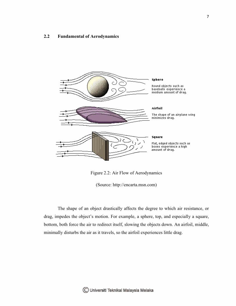
Figure 2.2: Air Flow of Aerodynamics
(Source: http://encarta.msn.com)
The shape of an object drastically affects the degree to which air resistance, or
drag, impedes the object’s motion. For example, a sphere, top, and especially a square,
bottom, both force the air to redirect itself, slowing the objects down. An airfoil, middle,
minimally disturbs the air as it travels, so the airfoil experiences little drag.