Aerodynamic of Forebody and Nose Strakes Based on F-16 ... · NASA Contractor Report 3053...
144
NASA Contractor Report 3053 Aerodynamic of Forebody and Nose Strakes Based on F-16 Wind Tunnel Test Experience Volume I: Summary and Analysis C. W. Smith, J. N. Ralston, and H. W. Mann CONTRACT NASl-15006 JULY 1979 https://ntrs.nasa.gov/search.jsp?R=19790019972 2018-06-05T16:09:35+00:00Z
-
Upload
nguyentuyen -
Category
Documents
-
view
221 -
download
1
Transcript of Aerodynamic of Forebody and Nose Strakes Based on F-16 ... · NASA Contractor Report 3053...

NASA Contractor Report 3053
Aerodynamic of Forebody and Nose Strakes Based on F-16 Wind Tunnel Test Experience
Volume I: Summary and Analysis
C. W. Smith, J. N. Ralston, and H. W. Mann
CONTRACT NASl-15006 JULY 1979
https://ntrs.nasa.gov/search.jsp?R=19790019972 2018-06-05T16:09:35+00:00Z

TECH LIBRARY KAFB, NM
NASA Contractor Report 3053
Aerodynamic Characteristics of Forebody and Nose Strakes Based on F-16 Wind Tunnel Test Experience
Volume I: Summary and Analysis
C. W. Smith, J. N. Ralston, and H. W. Mann General Dynamics Fort Worth, Texas
Prepared for Langley Research Center under Contract NASI- 15 006
runsA National Aeronautics and Space Administration
Scientific and Technical Information Branch
1979
I- -


I
Section
1.
2.
3.
4.
5.
TABLE OF CONTENTS
Title
LIST OF S~4#B()LS . . . . . . . . . . . . . . . . .
SlJMMARY .....................
INTRODUCTION ..................
THE WIND TUNNEL TEST PROGRAM .........
3.1 Evolution of Forebody Strakes on the F-16 ..................
3.2 Geometric Descriptions .......... 3.3 Scope of Strake Testing .........
ANALYSIS AND DESIGN GUIDELINE DEVELOPMENT. .
4.1
4.2
4.3
4.4
Lift and Drag . , . . . . . . . . . . . . . 4.1.1 General Discussion . . . . . . . . 4.1.2 Evaluation of Existing Predic-
tion Techniques . . . . . . . . . . 4.1.3 Correlation of Incremental
Lift and Drag . . . . . . . . . . .
Longitudinal Stability . - . . . - - . . . 4.2.1 Selected Low-Speed Data and
Discussion. - . . . . . - . . . . . 4.2.2 Selected Transonic Data and
Discussion . . . . . . . . . . . . .
Lateral/Directional Stability. . . . . . 4.3.1 Selected Low-Speed Data and
Discussion . . . . . . . . . . . . . 4.3.2 Selected Transonic Data and
Discussion . . . . . . . . . . . . .
Design Guidelines . . . . . . . . . . . . .
CONCLUSIONS AND RECOMMENDATIONS. .......
REFERENCES. ....................
Page
iv
1
2
4
4 6 8
9
9 10
12
14
18
19
20
23
24
25
27
30
32
iii
II III1 I I III I

LIST OF SYMBOLS, (Continued)
s,
TEF
WL
a
"break
P
71B
%I4
ALE
*LEi
'TE
A
Wing theoretical planform area
Trailing-edge-flap deflection angle
Water line of the full-scale airplane
Angle of attack of the wing chord plane
Angle of attack separating linear and non-linear lift curve regions
Angle of sideslip or Prandtl-Glanert parameter, Jl-ML
Non-dimensional span station separating inboard and outboard panels (See Figure 34)
m2(ft2)
deg
cm (in.)
df=g
d%
deg, --
Quarter-chord sweep angle deg
Wing leading-edge sweep angle
Strake leading-edge sweep angle
deg
deg
Wing trailing-edge sweep angle
Taper ratio of the theoretical wing planform
--
vi

1. SUMMARY
The YF-16 and F-16 developmental wind tunnel test pro- gram has been reviewed and all force data pertinent to the design of forebody and nose strakes extracted. Volume I of this study is reported herein and contains geometrical de- . . scriptlons, general comments, representative data, and the initial efforts towards the development of design guides for the application of strakes to future aircraft. Volume II of this study contains a complete set of these data without analysis and is reported in NASA CR-158922.
Longitudinal and lateral/directional data are presented for low-speed and transonic Mach numbers for families of nose and forebody strakes on several configurations that reflect different stages in the F-16 development. Included are simple wing-body configurations and highly blended wing-body- strake configurations. All have 40-degree-leading-edge-sweep wings with a nominal aspect ratio of 3.0.
It is concluded that the generation of incremental strake lift is primarily dependent upon the area affected by the strake vortex and that strake planform is of secondary impor- tance below the angle of attack for which vortex breakdown effects become significant. Forebody strakes can have bene- ficial effects on lateral/directional stability if properly designed. Nose strakes provide significant gains when added to the forebody configurations of this study.

._--_--- ----.- ~-
2. INTRODUCTION
Possibly the most distinguishing characteristic of the latest generation of fighter aircraft, the F-16 and F-18, is the utilization of forebody and nose strakes to provide sig- nificant 'increases in usable maneuver lift. These designs are the culmination of long and expensive design evolutions, which relied extensively on wind tunnel testing. This approach was required because no reliable aerodynamic predic- tion methods are available that address the highly complex flow field present at the moderate-to-high angles of attack under consideration. As a consequence, an extensive body of experimental aerodynamic data exists.
In particular, during the course of configuration develop- ment of the YF-16 Lightweight Fighter Prototype and the F-16 Air Combat fighter, General Dynamics wind-tunnel-tested many strake variations at subsonic and/ar transonic speeds. Strake effects noted in these data can be generalized in the sense that both conventional and highly blended configurations were investigated early in the YF-16 development program. The effects of variations in strake size, strake planform, strake location relative to the nose, strake span relative to the span of the wing, and leading-edge-flap deflection received considerable interest. Additionally, several different types of strakes were investigated. These consisted of strakes that extended from the forebody to the wing leading edge (forebody strakes), strakes that started at the nose and extended only a short way back on the forebody (nose strakes), and relatively short strakes that were placed aft of the nose but did not extend to the wing leading edge (canard. strakes).
The primary benefit attributed to the forebody strakes is a significant increase in usable lift at transonic speeds compared to a conventional wing configuration. During the development programs, General Dynamics found that significant interactions occur between the vortex flows generated by strakes, the wing and the empennage flow fields, and that the interactions can be favorable or unfavorable. While it is relatively simple to achieve a high maneuvering lift capa- bility with forebody strakes, it is necessary to tailor the strake-wing-empennage combination to enhance the moderate-to- high-angle-of-attack lateral/directional stability character- istics and thus make the additional lift usable. Another major fact encountered in the development programs is that some strake-wing configurations result in a deep-stall
2
~-_ - -_._.. __.-_ _._____ _-___ - _ _ - _ -.- -- .,__~ -Tc-- - . . . . -, -.
. * .,.,

situation at angles degrees; therefore, speed pitch-control range.
of attack in the range from 35 to 60 it is also necessary to evaluate low- effectiveness in this angle of attack
Forebody nose shape plays an important role in the high- angle-of-attack lateral/directional stability characteristics. The effects of nose shape can be minimized by employing nose strakes but, again, it is necessary to limit the nose-strake size to prevent adverse effects in pitch at high angles of attack.
The objective of this investigation is to -conduct a detailed review of all of the YF-16 and F-16 developmental wind tunnel data, select the data pertinent to strake design, and present them in a useful form complete with detailed geo- metric data. Initial efforts have been conducted herein to coalesce the experimental aerodynamic characteristics of strakes into a set of generalized design guidelines for the application of forebody and-nose strakes to future aircraft. Of particular interest are the geometric parameters that have the most significant effects on (1) the prevention of low- speed deep stall, (2) the development of lift capability at transonic speeds, and (3) the establishment of the limits on the usable angle of attack at transonic speeds that preserve satisfactory longitudinal and lateral/directional stability characteristics. The complete data base may be found in NASA CR-158922.
Northrop Corporation has been funded by the Air Force Flight Dynamics Lab to conduct a similar study dealing with the strake data obtained during the F-5 and YF-17 develop- ' ments. The results of this work are published in AFFDL TR 78-94.
3
-- _._----. --. --_- ___ --- --- - .- ,. : .:.. ,,I,-

- --_.- __. . . .~_ - _.._ 1. .: - I--- -- _ ..A’* _.-- _ _.- ..~ _^__ ^ - - -. - ..-. _
3. THE WIND TUNNEL
TEST PROGRAM
The YF-16 and F-16 aircraft are products of an extensive wind tunnel test developmental program. It was during the YF-16 test program that the many design features of the F-16 evolved. The resultant configuration is an integrated design incorporating:
o Forebody strakes for controlled vortex flow
o Automatically actuated leading-edge flaps
o Relaxed static stability
o Blended wing-body cross-section shape
o Single engine fed by a simple underslung inlet
0 Single vertical tail
o High-visibility canopy
The design evolution is discussed here to lay the ground- work for understanding the strake development and the impact of comparing strake effects from the multitude of configura- tions studied. Detailed descriptions of the strake geometry and summaries of the available wind tunnel test conditions pertinent to the evaluation of strake performance are also presented.
3.1 THE EVOLUTION OF FOREBODY STRAKES ON THE F-16
A study of the YF-16 aerodynamic features began in 1968. After intensified analysis in 1970-71 and wind tunnel tests in 1971-72, detailed designs were finalized in 1972-73. Con- figuration refinement and growth modifications continued through wind-tunnel testing until the Full-Scale Development (FSD) aircraft, F-16A and F-16B, were finalized in 1975.
Early design studies set the basic features of two very different design approaches. One was a simple wing-body- empennage design with a single vertical tail (Configuration 785, shown in Figure 1). Later in the program this design
4
7 r, - -- - _

I
was also tested with' a twin-tail arrangement (Configuration 786, Figure 2). The other approach was a highly blended wing-body with a wide lifting forebody and twin tails mounted on booms extending aft on either side of the engine exhaust nozzle. This design is known as Configuration 401F, an early version of which is shown in Figure 3 (Configuration 401F-2).
The best features of the two separate initial models were combined into one model and the resulting configuration refined through several tunnel entries to produce the final YF-16 design. Significant intermediate steps included the combination of the Configuration 785 afterbody with the Configuration 401F-2 forebody to obtain Configuration 401F-5, Figure 4, and the addition of afterbody shelves to which the horizontal tails were mated, Configuration 401F-lOA, Figure 5. Minor modifications continued through Configuration 401F-16F, which is similar to the YF-16 prototype lines.
The aerodynamic design concept of obtaining high-lift coefficients at transonic speeds by the use of wide forebody shapes has been an integral feature of most General Dynamics fighter designs since before the FX (F-15) competition. The concept was initially wind-tunnel-tested in 1966. Sharp, narrow forebody strakes were also investigated briefly at that time; however, it was then considered an advantage to produce the lift with a blunt leading edge in order to main- tain attached flow and greater leading-edge suction for lower drag.
The 401F-0 configuration was developed under that con- cept , and to accommodate the underslung single inlet, the forebody cross section was made elliptical (flattened on the lower surface), which blended into an upright triangular shape having rounded corners and finally blended into the wing. Available NASA test data on effects of body cross section on lift indicated that significant lift could be expected from the forebody. The first transonic test of the configuration verified these expectations.
However, the directional stability characteristics of the wing-vertical-tailed 401F-0 configuration exhibited a severe loss of directional stability at moderate-to-high angles of attack. In addition, the subsonic drag polar "breaks" occurred at lower lift coefficients than expected. Analysis of oil-flow-visualization photographs and force and moment test results utilizing FX and other research models (Uference 1) -showed that forebody flow separations and the
5

interaction of the resulting vortices with the wing and vertical tail flow fields were major causes of the stability problem.
At this point, NASA/Langley Research Center aerodyna- micists were consulted. They suggested that the lift of the wide forebody could be increased by sharpening the leading. edge to strengthen the vortices rather than weaken them as our earlier attempts had done. The point was that forebody separation is inevitable at very high angle of attack; there- fore, the lift advantages offered by sharp leading edges should be exploited. This also would allow the forebody vortices to dominate and stabilize the high-angle-of-attack flow field over the entire aircraft, even improving the flow over the outboard wing panels.
Two series of parametric forebody strake tests were initi- ated. A series of delta planform strakes were designed for testing on the conventional forebody aircraft Configurations 785 (single vertical tail) and 786 (twin vertical tail). The second series had curved planforms (gothic and ogee) and were designed for testing on the blended configuration, 401F-5. These two parametric transonic tests provided the basic data for all the other evolutionary forebody strake tests, which continued throughout the YF-16 and F-16 development as various design changes required re-evaluation of the strake effective- ness.
3.2 GEOMETRIC DESCRIPTIONS
All data presented herein were obtained with a 40-degree- leading-edge-sweep wing with a nominal aspect ratio of 3.0. The basic 26-square meter (280-square foot) wings, W3 and W3BB, were used on all of the YF-16 developmental configura- tions except Configurations 785 and 786, which used a 26- square -meter wing of different planform, W6. Later, F-16 versions utilized wings of 27.6 sq.m (297 sq. ft), W24, and 27.9 sq.m (300 sq. ft), W25. Each of these planforms is sketched in Figure 6.
A listing of all of the strakes and the configurations upon which they were tested is provided in Table 1. Also included are pertinent geometrical parameters, which consist of strake length, maximum width, exposed area and position on the forebody. Figures that provide sketches of the strakes on the appropriate forebodies are referenced in the table. After the initial strake tests on Configurations 785, 786, and 4OlF-2 through 401F-5, it became apparent that a forebody
6

strake would be part of the final configuration. As a con- sequence, tested.
forebody strake-off configurations were no longer The subsequent configurations have variations in
strake size, shape, and location but do not have definable strake geometry for the purpose of determining an explicit strake width and exposed area for Table 1.
Figures 7 to 20 present sketches of the strakes on the appropriate. forebodies. Figure 7 shows the delta planform family, 27-210, which was tested on the simple wing-body configurations, 785 and 786. Several canard-type strakes were tested early in the program on Configurations 401F-2 (Figure 8), 401F-4 (Figure 9), 401F-5 (Figure lo), and 401F-10A (Figure lla). Also, a gothic planform, 25, was tested on Configuration 4OlF-4 (Figure 9>, and several ogee planforms in addition to a delta and gothic strake were tested on Configuration 4OlF-5 (Figure 10). Slotted strakes, Z22A and 223, were also tested on Configuration 401F-5, as shown in Figure 10.
Later tests investigated small changes to blended strakes, generally ogee in shape (Figure lib to 14). Low-speed tests were also conducted with a variety of small rotating (vari- able incidence) strakes that formed a piece of a basic ogee strake, 233 (Figure 15). Larger sections of ogee planform strakes were also rotated, as shown in Figure 16. Nose strakes and additional canard strakes were also tested on the basic YF-16 configuration (Figure 17).
Initial designs for the trainer (two-place) version of the F-16 included fuselage stretches of 77.5 cm (30.5 in) and 113 cm (44.5in). Numerous forebody strakes with ogee planforms of various width and length plus a few nose and canard strakes were tested on these configurations (Figure 18).
The FSD aircraft has two major modifications from the YF-16: a 25.4 cm (10 in) fuselage stretch and an increased wing area from 26 to 27.9 sq. m (280 to 300 sq. ft). Fore- body-strake variations for this configuration are shown in Figure 19. Numerous nose strakes were also investigated as shown in Figure 20.
Several strake families have been selected for analysis purposes because they provide significant variations in strake geometry on the same basic configuration. Forebody- strake families that receive primary analysis are those of
7

Figure 7 (27-210, Configuration 785), Figure 10 (24, 25, Z14- 218, Configuration 401F-5), Figure lib (224-227, Configuration 401F-lOA), and Figure 18a (263-272, stretched YF-16). Nose- strake families of primary interest were tested on the F-16 FSD configuration and are shown in Figure 20 (2110-2117, 2123-2128, 2131).
Several nose shapes were tested at low speed in conjunc- tion with the nose strakes. Sketches of these noses are provided in Figure 21.
3.3 SCOPE OF STRAKE TESTING
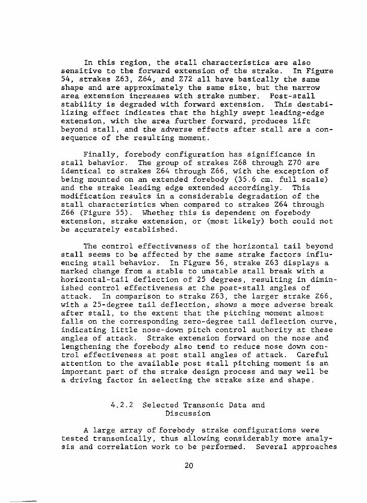
A list of all of the YF-16 and F-16 force tests is provided in Table 2. These tests encompass the entire developmental program from the early configuration testing in 1971 to the recent FSD testing in 1977. Each of these tests has been surveyed for data applicable to strake design, resulting in the selection of the tests shown in Table 3. A complete set of the resultant data for the tests of Table 3 are provided in plotted form in Volume II of this study (NASA CR-158922). Test parameters for each strake configura- tion are summarized in Table 4. Figure numbers in Volume II for data for each strake configuration are also provided in Table 4. Selected data are shown in this volume.
During the initial development program, emphasis was placed on the aerodynamic and stability characteristics at specific transonic Mach numbers (.80 and 1.20). Later test- ing included additional Mach numbers for selected configura- tions. Very little low-speed testing was accomplished until the configuration had evolved to basically that of the YF-16 (Configuration 401F-16). Much of the low-speed effort was associated with the evolution of the two-place aircraft dur- ing the Air Combat Fighter (ACF) competition and, therefore, includes effects of stretching and modifying the forebody shapes. The nose strake testing also occurred at the time of the ACF competition and later during the FSD program.
All of the low-speed testing was conducted at a Reynolds number of 1.4 million per foot. The transonic tests were conducted with a Reynolds number range of 2 to 3 million per foot. Reynolds number effects on high-angle-of-attack aero- dynamics may be significant; however, investigation of the effect of Reynolds number on the strake characteristics is beyond the scope of this document.
8

4. ANALYSIS AND DESIGN
GUIDELINE DEVELOPMENT
This study makes the strake wind tunnel test data obtained during the F-16 development available for general use. This is accomplished through the geometrical descrip- tions of Section 3 and the complete set of plotted data provided in NASA CR-158922. Since a large amount of data was obtained during a development program containing numerous configuration changes, assimilation of the data is not a simple task. The intent of this section is to concisely extract and present the trends observed from the data, using representative data to illustrate and substantiate the con- clusions. Where possible, initial steps have been taken to form general design guides. All deducements from the data must be tempered by the fact that high-angle-of-attack aerodynamics, and particularly lateral/directional stability characteristics, are strongly dependent upon the complete wing-body-empennage configuration. Assessments of the degree of general applicability of the conclusions reached, e.g., to configurations dissimilar to the F-16, have been attempted throughout the section.
4.1 LIFT AND DRAG
It is well-known that the addition of forebody strakes significantly increases the high-angle-of-attack lift and decreases the high-angle-of-attack drag of low- to medium- sweep wings. General observations as to the character and extent of these effects with respect to the strake geometry are presented in this subsection. The discussions are pri- marily concerned with strake effects on lift at moderate-to- high angles of attack. However, drag effects exhibit the same trends and will be shown to be a function of CL tancu as would be expected. A brief evaluation of an empirical prediction method for high-angle-of-attack lift has been made and the method found to be inadequate for strake configurations. This leads to empirical correlations of the strake lift and drag increments with the intent of producing design guides relating the aerodynamic effects to strake geometry. Results of these correlations are also discussed in this subsection.
9

4.1.1 General Discussion
Typical examples of the lift and drag benefits attributed to forebody strakes are shown in Figures 22 and 23. The family of delta planform strakes, 27-210, on the simple wing-body configuration (785) yields lift and drag benefits beginning at approximately a lo-degree angle of attack (Figure 22). The most significant geometric parameter appears to be the area: the bigger the strake, the more the lift. The data shown in Figure 23 are representative of the later highly blended strake configurations (geometry of Figure 18a) and as such, there is no strake-off level for comparison. The strong effect of strake size is nonetheless again present at angles of attack above 17 degrees.
The effects of nose strakes on lift and drag are negligi- ble for the size strakes tested in the F-16 program. A typical effect is that of nose strake 2124 tested in front of the F-16 forebody strake, 2120 (Figure 24). A sketch of 2124 was pro- vided in Figure 20b. This negligible effect is undoubtably a result of the small size of the nose strakes. A contributing factor, however, is also that the vortex shed from the nose strake tends to flow over the forebody and does not interact with the wing flow field. Conversely, a vortex shed from a forebody strake passes over the strake and wing upper surface. Further evidence of this concept is present in Figure 25, which compares the lift effects of a nose strake and a small canard strake for the YF-16 forebody (Figure 17 shows geometry). The canard strake, although small, has a noticeable effect on the lift and drag, particularly at very high angles of attack. A vortex shed from thiscanard strake would pass over the fore- body strake and wing, and tend to reinforce the existing fore- body strake vortex.
The data of Figures 22 and 23 show significant beneficial effects of forebody strakes on the lift and drag of a wing with no leading-edge flap deflection. Wing leading-edge flap deflections can significantly reduce the incremental strake effects. For example, on configuration 401F-5 without a forebody strake, increasing the leading-edge flap deflec- tion results in an orderly increase in lift with increasing angle of attack (Figure 26). However, the addition of a modified delta forebody strake, 24, significantly reduces the effect of the leading edge flap (Figure 27). There is actually a reduction in lift with leading-edge flap deflection in the 15- to 23-degree angle-of-attack range for the config- uration with strake 24.
10

The result is that the effects of forebody strakes on the envelope lift and drag curves, which are representative of aircraft,' such as the F-16, that have scheduled leading- edge-flap deflections, are significantly reduced from the no-leading-edge-flap case. Envelope curves (Figure 28) that result from a minimum-drag leading-edge-flap schedule illus- trate this point. This effect is logical when the effect on the wing upper surface flow is considered. Without a leading- edge flap or a strake the flow over the F-16 wing, which is rather thin (t/c = .04), begins to exhibit significant separa- tion (stall onset) at approximately a lo-degree angle-of- attack (Figure 22). A leading-edge flap delays this separa- tion considerably and thus improves the lift and drag charac- teristics. A forebody strake accomplishes much the same effect at high angles of attack by passing high-energy vortex flow over the region of the wing that otherwise would have separated (stalled) airflow. These effects are not entirely additive, thus the strake benefit in the presence of leading- edge flaps is reduced from the no-flap case, Figure 28. In summary, the design of a forebody strake/wing leading-edge flap combination must consider the strong coupling effects.
The comparisons of Figure 28 are with a zero horizontal- tail deflection, i.e., untrimmed. Trim effects are generally favorable to the forebody strake configurations because of the linearization of the pitching moment curve, as will be discussed in Subsection 4.2.
Whenever additional exposed area, such as a strake, is added to a configuration to improve the high-angle-of-attack characteristics, the question of the effect on cruise and dash performance must be addressed. Figures 29 and 30 illus- trate the typical low-lift drag penalty for forebody strakes at .80 and 1.20 Mach number, respectively. The predicted skin friction drag (Reference 2) for thelargest strake shown, 27, is .0007 at wind tunnel Reynolds number and .80 Mach number. It can be seen in Figure 29 that the data for all of the strakes fall within this band at the lift coeffi- cient for minimum drag, indicating that the drag penalty is of the same order as the friction drag prediction at .80 Mach number. The penalty remains relatively constant up to typical optimum-altitude cruise lift coefficients for the F-16 (CL = .3). Figure 30 shows that at 1.20 Mach number some strakes produce a small drag reduction at low lift. It is probable (based on.area distributions from similar configura- tions) that for this unblended configuration (785) the strake is filling the area curve immediately forward of the wing, thus improving the airplane's 1.2 Mach area distribution.
11

The majority of the transonic strake parametric data is at Mach numbers of .80 and 1.20. Limited conf%guration com- parisons are available at .90 Mach. Although the strake effects on lift and drag are, in general, consistent betwe.en .80 and .90 Mach, the effects are greatly reduced at the higher Mach number. Figures 31 and 32 illustrate this effect for a series of blended forebody strakes on Configuration 401F-10A.
The effect on lift and drag of fairing the strake into the forebody is shown in Figure 33. The basic 24 strake is a flat plate added to Configuration 401F-5. This strake was first tested with the upper surface faired, Z4A, and then the upper and lower surfaces faired, Z4B (geometry in Figure 10). There are only very small effects on the lift and drag.
Of primary importance in this subsection is the effect of forebody strake size and shape on lift and drag and the associated interaction of the strake and leading-edge flap. These items are therefore considered in more detail in the following subsections.
4.1.2 Evaluation of Existing Prediction Techniques
If an existing method would adequately predict lift and drag effects of forebody strakes, it would be a considerable aid to the definition of the important geometrical relation- ships and associated development of design guides. To this end, a typical existing method has been evaluated. The method selected for consideration is an empirical method developed at General Dynamics under a USAF contract (WINSTAN) and documented in Reference 3. The contract task was to develop methods to predict the aerodynamic characteristics of double delta, cranked, and curved leading-edge wings. The particular aspect of interest herein is the method developed to predict the nonlinear lift of double-delta planforms.
The method is based on a correlation at constant angle of attack of the parameters (CL/CL,)(ARi/?R) and ptan ALEi for available experimental data for double-delta planforms. These parameters are defined as follows:
CL - lift coefficient, lift/qSR&
cL,! - linear lift curve slope
12

. 2
ARi - aspect ratio of inboard panel, bi /Si
TlB - nondimensional span station of intersection of inboard and outboard panels
P - Prandtl-Glauert parameter, Ji??
*LEi - leading-edge-sweep angle of inboard panel
The resultant correlation, taken from Reference 3, is shown in Figure 34.
To apply this method to predict the incremental effects due to strakes, it is necessary to predict both the strake- on and strake-off configurations. The strake-on case is predicted as if it were a conventional double-delta planform. The strake-off case is predicted by assuming that a double delta planform approaches the wing-fuselage combination as a limiting case. It is noted in Figure 34 that as the sweep of the inboard panel approaches 90 , the parameter (CL/CLJ (ARi/?B) approaches an asymptotic value. The strake-off case is predicted by use of this asymptotic value as repre- sentative of a wing-body combination with the fuselage forward of the wing trailing edge defined as the inboard panel.
The family of delta planform strakes shown in Figure 7 has been selected for the test-prediction comparison because of its configuration simplicity. These strakes are not blended into the fuselage, thus the definition of each con- figuration component is straightforward. These strakes also form a consistent family, not involving several different planform shapes.
The predicted increment between strake on and off is shown in Figure 35. Obviously the increment predicted in this manner does not adequately model the increment obtained from the test data. It is noted that the strake does not produce a substantial lift increment within the range of angles of attack normally considered to be characterized by linear (or nearly linear in the case of the F-16 aspect ratio 3.0 wing) variations in lift. An attempt has been made to account for this region by predicting the "break between the linear and nonlinear lift regions and utilizing the increment above this point to predict the strake effects.
A correlation of abreak and leading-edge-sweep angle of the inboard panel is presented in Reference 3 for an
13

uncambered wing. The effect of wing camber on abreak is estimated by use of an empirical correlation found in Reference 4 and repeated below.
abreak = (12.05 -4.lMcos A c/4) 'cosc4\dc,4)
The strake-on and -off predictions are collapsed at the value of abreak predicted by the above method, and the increment above this point used to predict the strake effects, as shown in Figure 36. This is an adaptation of the double- delta method, which is similar in approach to the adaptation used in Reference 3 for cranked wings.
Prediction using this technique is shown in Figure 37. This adaptation of the double-delta correlations predicts the order of magnitude of the strake lift, although the ef- fects of angle of attack and strake geometry are not always predicted correctly.
The apparent failure of the double-delta method of Reference 3 to adequately model the incremental strake effects does not discredit the method with respect to its original intended use. The method is based on correlations of conventional double-delta planforms of relatively high sweep and low aspect ratio. The outboard wing panel of the configurations within the present study have in all cases a moderate sweep angle (40') and aspect ratio (3.0). In addition, the incremental values used for comparison are dependent upon the ability to predict the strake-off levels at high angles of attack - a purpose for which the methods of Reference 3 were not originally intended.
Some of the more recently developed computerized methods show promise for evaluating the longitudinal aerodynamic characteristics of wing-body-strake configurations. For example, an adaptation of the Polhamus suction analogy concept is shown to reasonably predict forebody strake effects on a basic wing-body research model in Reference 5.
4.1.3 Correlation of Incremental Lift and Drag
Due to the lack of a fully adequate method to predict the strake incremental effects, attempts have been made to
14

correlate the effects with appropriate geometrical param- eters. This effort is difficult due to the lack of a consistent baseline from which to increment. As discussed previously, most of the configurations with strakes are highly blended strake-wing-body combinations, and a true strake-off configuration does not always exist for incre- mental purposes. For these cases, the incremental values studied represent the effect of modifying an existing strake and not the total strake effect per se. Furthermore, not enough consistent families of strakes exist to systematically define the effect of a particular geometric variation. How- ever, within the context of these limiting factors, corre- lations can be made that lead to several interesting con- clusions concerning the general effects of forebody strake geometry.
Initial observations noted in Subsection 4.1 indicated a strong effect of strake area on the incremental lift. If indeed area is the dominating factor, it would be helpful to remove this effect from the data so that effects that are perhaps secondary can be identified. A first attempt at this consisted of referencing the strake incremental lift to the exposed area of the strake, thereby obtaining a pure strake lift coefficient. Results showed that the exposed area was much too small to collapse the data. At this point it was hypothesized that the strake incremental lift would be a direct function of the total area affected, or energized, by the strake vortex. This is similar in concept to the augmented vortex method developed by Lamar (Reference 6). Due to the lack of diagnostic data to determine the area being influenced by the strakes, a geometrical definition of an area considered to be repre- sentative was necessary. The definition of such an area is illustrated in Figures 38 and 39. For conventional strake- wing-body-combinations, the definition is simply the exposed strake area plus the wing planform area that falls within the projected strake exposed area, as shown in Figure 38. For the highly blended configurations, which do not have well-defined strake planforms, the definition was not as straightforward. For these configurations, the blended area between the strake and body was included with the strake exposed area as illustrated in Figure 39.
Four families of strakes were tested for which a defi- nite strake-off baseline exists. The incremental lift data referenced to the theoretical wing area (26 square meters, 280 square feet) for these families are shown in Figures 40 through 43. Strake geometry was shown in Figures 7, 10 and
15

lib. The lift increments referenced to the strake-wing effective area, as defined in Figures 38 and 39, are shown in Figures 44 through 47. The lift increments tend to col- lapse to a single curve for a fixed value of wing leading- edge-flap deflection.
This is an important fact. It says that for a given configuration the overriding factor in determining the strake lift is the area affected by the strake generated vortex for the angle of attack range tested. Shape effects should become more pronounced in the 30 degree angle of attack range where vortex bursting will occur over the lifting surface.
An exception to the area correlation is the ogee family of data (Figure 46) at angles of attack greater than 18 degrees. Strakes 216, 218, and 217 intersect the wing at increasing semi-spans. It can be speculated that for the larger span strakes (217 for example) the effective area needs to be redefined to include less of the inboard part of the wing, as shown in Figure 48. This would tend to further collapse the data of Z16, 217, and 218 in Figure 46 at high angles of attack. Strake 214 is the least effec- tive of those shown in Figure 46, which may indicate that it is too narrow to generate as strong a vortex as, say, Z18 (which has the same span).
Divergence of the effective area-based data at the higher angles of attack can also be caused by the sweeping of the strake vortex outboard over the wing. Typically, below about 20 degrees angle of attack the vortex passes across the wing in a streamwise direction for the F-16 configuration. However, at higher angles of attack (depend- ing on leading edge flap deflection) the path of the vortex begins to curve spanwise over the wing. Obviously, the effective area definition would have to be modified to represent this effect.
Average fairings representing the collapsed data of Figures 44 through 47 are shown in Figure 49 for each family. Variations in strake shape are of only secondary importance to the generation of lift, as shown by the lo- degree flap data on Configuration 401F-5 for delta (Z4), ogee (214, Z16-Z18), and gothic (25) planforms. Figure 49 also shows that the incremental lift decreases for the more highly blended configurations. Configuration 401F-10A is the most highly blended configuration shown in Figure 49 and has the lowest incremental strake lift. Configurations 785 (simple wing body) and 401F-5 (blended) show approximately
16

the same level of strake lift to 18 degrees angle of attack. This is fortuitous, however, because the strakes of Configu- ration 785 have a nominal negative 2 degrees of incidence at the leading edge relative to those of Configuration 401F-5. The strakes on the simple wing body would be more effective at high angles of attack if they were at the same incidence as those of Configuration 401F-5.
A definite dependence on wing leading-edge-flap deflec- tion can be noted in the lift increments of Figure 49. De- flecting the leading-edge flap delays the beneficial strake effects to a higher angle of attack as discussed previously in Subsection 4.1.1.
A substantial amount of strake data is available that cannot be analyzed in the preceding manner due to the lack of a true strake-off baseline. This is the case for many of the highly blended strake-wing-body configurations. For these configurations, the strake of smallest exposed area was selected as the baseline for all force increments. The incremental lift for two such families of strakes is shown in Figure 50 referenced to the wing area (26 sq. m, 280 sq. ft) and in Figure 51 referenced to the change in strake ef- fective area from the baseline strake configuration. There is a tendency for these increments to collapse, although it is not as definite as noted in the previous comparisons. The strakes with the smallest changes in area from the base- line (264 and Z71), and thus the smallest lift increments (Figure 50), correspond to those curves in Figure 51 that fall the furthest away from the main body of data. Here small increments are being referenced to small areas, and a sensitivity factor may be involved. Or it may be that ex- tension of the strake forward, 263 to 264, is a relatively efficient method (it takes less area) to increase the lift in the 20- to 30-degree angle of attack range because it provides a longer growth time for the vortex. More data is required to isolate this effect.
Since the forebody strakes tested on the F-16 are of high sweep and have sharp leading edges, it is expected that the drag, ACD, due to the strake lift, AC would be close to the no-suction value, ACL tana! . Thik'has been evaluated in terms of incremental strake lift and drag in Figure 52 for several strakes with zero leading-edge flap
17

.
deflection. Since strakes 27-210 have leading-edge inci- dences of nominally 2 degrees, the angle of attack has been appropriately modified. The data are reasonably approxi- mated by an adaptation of the Reference 3 methodology for double delta wings;
ACD = .95 ACL tan (a+ i)
Some data scatter is apparent at the lower angles of attack, but the data generally fall within +_ 2 percent of the total strakeoff configuration drag.
4.2 LONGITUDINAL STABILITY
The addition of strakes, particularly forebody strakes, to a wing-body configuration produces changes in airplane longitudinal characteristics. The purpose of this portion of the investigation, therefore, is to examine the available wind tunnel data in order to define pertinent strake design factors, such as strake shape, area, location, etc., that have significant effects on longitudinal stability.
Proper strake design and location can result in a beneficial influence in maneuver lift, directional stability, and/or longitudinal stability at high angles of attack. In the longitudinal case, strakes can yield improved linearity of pitching moment characteristics, particularly in the transonic regime where wing stall usually results in-a large stable break of the pitching moment curve. It was observed early in the analysis that available nose strakes had a small effect on the longitudinal characteristics (presumably because of their relatively small exposed area with respect to wing area) and were, therfore, not included in this longitudinal analysis. Forebody strakes, on the other hand, do affect longitudinal characteristics and in some cases introduce nonlinearities. These will be identified and reviewed.
The nature of the strake's effectiveness, its vortex generation, and effects on the wing and forebody, is highly dependent on the general configuration of the aircraft. Iso- lation of these effects (particularly in regard to stability characteristics) is difficult considering that nearly every family of strakes as tested was on a different forebody con- figuration, making overall correlation difficult. Additional limitations are imposed on the low-speed analysis, since relatively few forebody strakes were tested in this flight regime, and, of those that were, no corresponding strake-off condition was available. 18

4.2.1 Selected Low Speed Data and Discussion
For both subsonic and transonic cases it is apparent from References 7 and 8 and the data of the present study that the major influences on the forward shift of aero- dynamic center due to the strake are the strake's exposed area and its location ahead of the wing. The faired ogee- shaped strakes of Figure 18a are the only forebody strake family that was tested at low speed, but no strake-off case was tested. However, the variation of geometries within this family provided information as to trends due to certair design factors.
Within the linear CL region at 0.2 Mach number, it is apparent that the primary strake characteristic influencing the change in the a.c. is its area directly ahead of the wing. For example, strakes 263 and 264, which have similar planforms, except that 264 extends approximately 102cm(40in) further forward on the nose, have essentially the same a.c. location (Figure 53). Configurations 265 and 266, both of which retain the extension forward and the basic shape of 264 but increase the areas in the region in front of the wing, yield proportional decreases in pitch stability. These data indicate that either the more powerful vortex produced by the larger area in front of the wing or the effect of the basic wing upwash, or both, tend to make this portion of the strake highly effective in influencing the overall a.c. location in the linear region of lift. Insufficient low- speed strake data precluded exact determination of shape effects.
The region above the linear CL is crucial from a strake design standpoint, primarily because of the effect of the strake on the airplane stall and post-stall characteristics. The addition of forebody strakes enable the wing-strake combination to continue lifting to angles of attack of 30 to 40 degrees, whereupon the combination stalls. The pitching moment curve, linear up to stall in most cases, tends to break erratically stable or unstable after stall, depending on the configuration (see Figure 53). The nature of the pitching moment break after stall is extremely important to the prevention of a deep (unrecoverable) stall. As in the lower-angle-of-attack region, strake area has a major influ- ence, the larger strake (Z66) exhibiting the most unstable break (Figure 53). MO guidelines as to area requirements could be formulated from the available data because of the geometrical limitations discussed above.
19
In this region, the stall characteristics are also sensitive to the forward extension of the strake. In Figure 54, strakes 263, 264, and 272 all have basically the same shape and are approximately the same size, but the narrow area extension increases with strake number. Post-stall stability is degraded with forward extension. This destabi- lizing effect indicates that the highly swept leading-edge extension, with the area further forward, produces lift beyond stall, and the adverse effects after stall are a con- sequence of the resulting moment.
Finally, forebody configuration has significance in stall behavior. The group of strakes 268 through 270 are identical to strakes 264 through Z66, with the exception of being mounted on an extended forebody (35.6 cm. full scale) and the strake leading edge extended accordingly. This modification results in a considerable degradation of the stall characteristics when compared to strakes 264 through 266 (Figure 55). Whether this is dependent on forebody extension, strake extension, or (most likely) both could not be accurately established.
The control effectiveness of the horizontal tail beyond stall seems to be affected by the same strake factors influ- encing stall behavior. In Figure 56, strake 263 displays a marked change from a stable to unstable stall break with a horizontal-tail deflection of 25 degrees, resulting in dimin- ished control effectiveness at the post-stall angles of attack. In comparison to strake 263, the larger strake Z66, with a 25-degree tail deflection, shows a more adverse break after stall, to the extent that the pitching moment almost falls on the corresponding zero-degree tail deflection curve, indicating little nose-down pitch control authority at these angles of attack. Strake extension forward on the nose and lengthening the forebody also tend to reduce nose down con- trol effectiveness at post stall angles of attack. Careful attention to the available post stall pitching moment is an important part of the strake design process and may well be a driving factor in selecting the strake size and shape.
4.2.2 Selected Transonic Data and Discussion
A large array offorebody strake configurations were tested transonically, thus allowing considerably more analy- sis and correlation work to be performed. Several approaches
20

were followed. As mentioned earlier, the addition of strake area ahead of the wing would be expected to produce a destab- ilizing effect on longitudinal stability, essentially propor- tional to the strake size and its positioning ahead of the wing.
The a.c. shift has been correlated with pertinent strake parameters. On the basis of the results of the lift incre- ment analysis of Subsection 4.1.3, the strake is assumed to be a low-aspect-ratio wing spanning from the body/strake juncture to the wing-leading-edge/strake intersection and inclusive of the portion of the wing directly aft of the strake (the shaded areas in Figures 38 and 39). Geometrical data for the resulting strake/wing inboard panel for several strake configurations are given in Table 5. Representative leading-edge sweeps were selected for the curved strakes as shown in Table 5. The strake lift curve slopes, CL and the non-dimensional distance from the aerodynamic ce"nfer of the constructed strake area to the aerodynamic center of the basic wing alone, ,!,/c, are predicted by the methods of Reference 9 and 10,respectively. The predicted values are presented in Table 6 with corresponding parameters
&AEFF and jsAEFF 'L, The relation between the change
%EF =REF S’
in the a.c. in the linear CL region (less than 10 degrees angle of attack) due to the strake (AAC ) and the parameter 1 @EFF CL is shown in Figure 57 for the various families
FSREF %
noted. For all of the strakes investigated, regardless of i shape, flap deflection, or fuselage configuration (785 and 401F-5), a linear relationship of a.c. with
'sAEFF was essentially obtained. Only strake 217
%EF CLas
falls considerably off the correlating line. This is believed to be a result of the affected area definition for large span strakes, as described in Subsection 4.1.3. A similar linear relationship is shown in Figure 58 for the strakes tested at Mach 1.2. Such a relationship of a.c.
with 'sA-EFF =kEF cL suggests the stability change in the linear
%
lift region due to the addition of the forebody strake is a function of the lift produced by the strake and its influenced
21

area on the wing, and it shows promise for the development of a semi-empirical prediction method for strakes similar to the Paniszczyn a.c. prediction method for cranked wings of Reference 3. At this time, estimation of the strake effect on aerodynamic center in the linear lift region can be roughly determined by use of the relationship established in Figures 57 and 58.
AACl = 0.483 'sAEFF %Ys at 0.80 Mach number
CS REF
4AC1 = 0.296 &FF %Ys at 1.20 Mach number
CS REF
Efforts to establish the change in a.c. due to strakes in the nonlinear lift region beyond the initiation of wing stall (nominally 10 degrees angle of attack) provided the results shown inFigure 59. For this nonlinear lift region the stability change ( 4AC2) is correlated with the
parameter 'sAEFF
2 . Note that the lift curve slope term is
REF omitted, primarily because of the characteristic nonlinear lift variation of low-aspect-ratio wings at high angles-
of attack. All strake configurations exhibited essentially the aame linear variation in a.c. with the parameter
@EFF - for given leading-edge-flap deflections.
CSREF Deflecting the leading-edge flap in the nonlinear lift region reduces the shift due to the strake (as expected, based on the reduced lift, Figure 49). For strake configuration 24 and a flap deflection of 25 degrees, there is a noticable change in stability over the strake-off configuration, although for this flap deflection the increment in lift due to the strake is small (Figures 26a and 27a). Thus strakes can provide beneficial linearization of the pitching moment even when the flap effects reduce the increment in lift due to the strakes.
An additional lateral shift between Configuration 785 and 401F-5 is shown in Figure 59. This is probably due to the fuselage blending of 401F-5, which results in further forward strake-off a.c. location and a smaller overall shift in a.c. due to the strake.
22

Examination of the data contained in Tables 5 and 6 indicate that the strake shapes tested seem to evidence negligible effects longitudinally at transonic speeds. The, strake shape is, however,of considerable importance in the
lateral directional case, as will be discussed in the follow- ing subsection
4.3 LATERAL/DIRECTIONAL STABILITY
Maintaining directional stability to maximum usable lift is of major importance in the design of high-performance maneuvering aircraft. Generally progressive deterioration in static directional stability begins at moderate-to-high angles of attack for most conventional configurations and, consequently, limits the maximum usable lift. Strakes, both nose and forebody, have proven effective in extending the usable lift range. Herein, families of nose strakes and forebody strakes are systematically reviewed to establish their effectiveness on lateral/directional characteristics in order to formulate a strake design guide toward extending the usable lift range.
The adverse effects on lateral/directional stability due to vortex flow shed by the fuselage nose and wing-body juncture, and the associated destablizing flow field on the fuselage afterbody and at the vertical tail, have been investigated and reported in References 7 and 8. Addition of strakes, both nose and forebody,were found to produce improvements in lateral/directional characteristics, parti- cularly at high angles of attack by altering the generated vortex flow patterns.
A survey of catalogued strake lateral/directional data revealed a lack of systematic strake geometry variation. Consequently, practical considerations result in different investigation techniques based upon the kind and amount of strake data available. In contrast to developing quantita- tive results, the strake lateral/directional analyses are qualitative in nature on the basis of the available data. Several reasons are addressed in support of a qualitative analysis. First, strakes are predominantly effective at high angles of attack within a region in which vortex and separated flow are extremely complex and directly dependent upon numerous aircraft variables (e.g., forebody configura- tion,' wing sweep, vertical-tail geometry, etc.). Analysis is complicated further by the numerous fuselages on which the strakes were tested and the large nonparametric varia- tion in the combinations of strakes, tails, and forebodies.
23

Additional complications arose in that most nose strakes were tested subsonically while the forebody strakes were primarily tested transonically (one family series was tested subsoni- tally).
4.3.1 Selected Low-Speed Data and Discussion
Especially at low speed and moderate to high angles-of- attack nose strakes have a pronounced effect on lateral/ directional stability characteristics. Improvement in lateral/directional stability is influenced by the size (length and width) of the nose strake. Each baseline con- figuration used in the nose-strake evaluations had an inte- grated forebody strake. In all cases, the improvement in lateral/directional stability due to the nose strake over the baseline forebody strake case is significant. Typical results are displayed in Figure 60 for nose strake 2124 applied to forebody strake Configuration 2120 (faired ogee). The strake width and extension aft are the most significant design parameters. A typical example of the effect of nose strake extension for a family of truncated strakes is shown in Figure 61. The wider nose strakes also result in better lateral/directional characteristics (2112 vs 2114 in Figure 62). Actual strake shape seems to be of little consequence; how- ever, truncation of the strake (e.g., 2112, 2114) improves stability, especially laterally, compared to the same strakes faired back into the fuselage (2110, 2113 in Figure 62).
Slight inclination of the strake with respect to the aircraft waterline is of minor consequence. This is shown in Figure 63 in which strake 2128 is rotated 5 degrees up with respect to strake 2124 (both have same planform).
As mentioned earlier, the forebody strakes were not found to be as effective lateral/directionally as the nose strakes for the wing-body-strake configurations tested in the F-16 program. Actual measurement of the forebody strake's effectiveness over the strake-off configuration was not possi- ble since no strake-off configurations were tested at low speed. The variation of strake geometric parameters (leading- edge extensions and width) in the one family tested (263-270) displays few predictable trends since the data become quite erratic at higher angle of attack (Figure 64). The extended strake/forebody configurations (267-270 in Figure 65) are noticeably less stable than the corresponding shorter fore-
24

body combinations (263 - 266 shown in Figure 64). All con- figurations incorporating this family of strakes became directionally unstable beyond an angle of attack of 32 degrees.
The significant difference in effectivenss between the two types of strakes leads to the following postulation for the F-16 type configuration. Without nose strakes the shed vortices from the forebody emanate from variable locations along the nose depending on the angle of attack, sideslip, configuration, etc. With nose strakes applied, especially the truncated nose strakes, the location of vortex initiation is fixed and the vortex is directed along the fuselage after- body and vertical tail in a more symmetrical manner resulting in improved lateral/directional behavior. The effectiveness of forebody strakes on directional stability is not as signifi- cant as the effectiveness of nose strakes since the forebody strakes tend to be located behind the initiation point of forebody vortices, plus the probability that their vortices are affected by the flow field surrounding the wing. However, it must be stressed that the effects of both nose and forebody strakes and their interactions are extremely configuration oriented and the results from this set of data are not neces- sarily representative of other configurations.
4.3.2 Selected Transonic Data and Discussion
The nose strakes tested at transonic speeds were limited to a small number of configurations. The few that were tested again exhibited an improvement in the lateral-directional stability compared to the forebody-strake-alone case, for example nose strake ZlOO (Figure 66). The first three fami- lies of forebody strakes tested offer the best comparative basis for the effects of changes to the strake geometry.
The delta-shaped family of strakes displayed rather small effects with respect to directional stability but large changes laterally with the leading-edge flap deflection set at zero (Figure 67). In this case, thelargest strake of the family, 27, exhibited an extremely destabilizing increment in dihedral effect. This family of strakes has significant anhedral, (see in Figure 7) which may contribute to this ef- fect. Subsequent leading-edge-flap deflections decreased the over-all effects exhibited by strakes 27 and ZlO (Figure 68).
25

The second family, strakes 24 (modified delta) and 25 (gothic) exhibited improved directional stability behavior over the strake-off case (Figures 69 and 70). The change in lateral characteristics with leading-edge-flap deflection is not as great for this family (Figures 69 and 70) as for the delta-shaped strakes (Figures 67 and 68).
The third family, 214 and 216 - 218 (ogee) show improve- ment in directional stability with adverse effects laterally with the leading-edge flap deflected 10 degrees (Figure 71). Because this was the only flap condition tested, flap effects could not be determined.
These results support some general conclusions. Adjust- ment of the forebody strake shape has definite effects on the lateral/directional stability, regardless of leading-edge- flap deflections. The most pertinent geometric parameters tend to be the extension of the strake forward on the nose and the width of the strake at this point. These trends are supported by the improved characteristics of the strakes 24 and 25 (Figures 69 and 70). Of the first three families, 24 and 25 extend furthest forward with the greatest width in the forward region. This conclusion is further supported by the relative stability within the fourth (224 - 227) and fifth families (228 - 233). For each family, the strake that extends furthest with the greatest width toward the nose (strakes 225 and 228, respectively) show the greatest improve- ment over the strake-off case (Figures 72 and 73). The reasoning behind this behavior agrees with the demonstrated subsonic stability improvements of the nose strakes compared to forebody strakes. For both cases, the obvious area of effectiveness lies forward on the nose. In that forebody strakes usually lie behind the shed point of the forebody nose vortices, their effect on lateral directional stability tends to be much less than properly positioned nose strakes. Only for cases in which the forebody strakes extend considerably forward on the nose do they show significant stability improvements. A contributing factor to the improved stabil- ity for some forebody strakes is the formation of a stronger, more stable vortex. This vortex, when sufficiently strong, provides a stabilizing influence on the wing flow field and in the afterbody region.
26

Obviously, the lateral/directional benefits attained through the use of strakes are of primary concern to any air- craft design. It is suggested that in configuration develop- ment well-structured testing be performed to thoroughly determine the influence of strakes on stability. In addi- tion, care must be taken when combining nose and forebody strakes because the interactions can become significant and effects noted from separate testing are most likely not linearly additive.
4.4 DESIGN GUIDELINES
The analysis and resulting conclusions presented in the preceding sections have been qualified by the configurational dependence of high-angle-of-attack aerodynamics. However, some initial design guidelines have been developed that are believed to be valid for rather general application (at least to configurations with outboard wing panels and single verti- cal tails similar to the F-16). These are summarized in this subsection,
In addition to increased wing-body lift, one of the primary purposes for adding a forebody strake to a configura- tion is the linearization of the pitching moment curve at high angles of attack. Elimination of the typical strong stable break results in significant improvements in trim drag, which results in additional positive increments in maneuver lift.
Estimation of the aerodynamic-center shift in the linear lift region due to strakes can be made with the relations shown in Figures 57 and 58:
AACl = .483 &FF cL W
at .80 Mach number 2 PZF
and
AAC1 = .296 lsAEFF ks at 1.20 Mach number
CS REF
27

The strake lift curve slope, ($,os, and moment arm, is, are
estimated by the methods of References 9 and 10, as described in Section 4.2. The effective strake area, AEFF, is defined as shown in Figures 38 and 39.
The aerodynamic-center shift above the linear region can be estimated from Figure 59. Since all configuration leading-edge-flap combinations have the same slope
( &%FF ZrS
versus AAC2
REF >
, the effects of variations in strake
size can easily be estimated for a particular configuration. Thus, Figure 59 can be used to size a forebody strake to provide a linear pitching moment curve.
The incremental lift effects of forebody strakes are primarily a function of the affected area, as defined in Figures 38 and 39. This means that given a particular strake, leading-edge flap, and body configuration, the lift increments that can be obtained by modifying the strake (e.g., to the strake area required for a linear pitching moment curve) are easily estimated up to the angle of attack for vortex breakdown (which may vary for different strake planforms).
Furthermore, incremental lift and the stability shift due to adding a strake to a simple wing-body configuration or a blended configuration can be estimated to the first order with the curves of Figures 49 and 59 by simply selecting a similar configuration. The incremental drag resulting from the strake lift can also be obtained by use of the relation derived from the correlation shown in Figure 52:
ACD = . 95 ACb tan (o+ i)
At this time general design guides have not been devel- oped for lateral/directional stability or low-speed stall characteristics because of the large configuration-dependence of theseitems and the lack of parametric information. Addi- tional, well structured, testing is required to properly isolate the effects of strake geometry on these phenomena.
28

However, several general comments are appropriate. Care should be taken in the design of strakes to maintain adequate control capability in the post-stall region. This is a function of strake size and shape as well as tail size. Based on the data presented herein the effects of forebody strakes on lateral/directional stability become more pro- nounced when the strake is extended far forward on the nose.
Nose strakes strongly influence directional stability at high angle of attack. Results from the present study imply they should be truncated for best lateral characteristics. Additional important geometric parameters are the width and length. Caution is required when combining nose and fore- body strake stability effects because the interactions can become significant and the effects noted from separate test- ing are most likely not linearly additive.
29

5. CONCLUSIONS AND
RECOMMENDATIONS
Nose strakes offer significantly improved lateral/ directional performance with a minimum increase in wetted area and little effect on longitudinal characteristics. Forebody strakes provide beneficial linearlization of the pitching moment curve, improved maneuver lift, and in some cases, improved lateral/directional characteristics. Al- though the application of the strakes is highly configura- tion-dependent and optimization will undoubtedly require tun- nel testing, initial design guidelines have been developed and several recommendations can be forwarded.
Design guidelines have been developed that allow fore- body strakes to be sized to obtain a linear pitching moment curve and the resulting lift and drag increments to be esti- mated. The incremental lift effects have been shown to be primarily a function of the area affected bythe strake induced vortex. Forebody-strake-planform shape is of sec- ondary importance to lift generation below vortex breakdown but has a significant effect on lateral/directional charac- teristics.
The shape of nose strakes for lateral/directional stability seems to be of minor importance. The major posi- tive influences are found to be the width of the strake and the truncation of the surface, that is, cutting it off rather than fairing it back into the fuselage. The nose strakes analyzed have little effect on longitudinal stability; how- ever, increasing surface widths, and consequently area, may lead to possible adverse effects in the subsonic high-angle- of-attack region.
Forebody strake effects on lateral-directional stability are most pronounced with no leading-edge flap deflection. The lateral-directional effects appear to increase as the strake is extended forward on the forebody. The extension forward on the nose, however, becomes undesirable from the standpoint of subsonic longitudinal stability at high angles- of-attack.
A need has been identified for further well-structured parametric testing designed to isolate the effects of strake geometry on, in particular, the lateral/directional-stability
30

and low-speed-stall characteristics. It is recommended that systematic families of forebody and nose strakes be designed for a simple wing-body configuration with single and twin vertical tails and these definitive tests. conducted. These data will also serve to verify and/or expand the initial design guidelines that have been developed for longitudinal effects.
31

1. J. D. McAllister, D. B. Benepe, P. D. Whitten, and G. Kaftan, Wing Roll Control Devices for Transonic High Lift Conditions, Part 1 - Fixed Wing Configuration, Volume 1 - General Configuration, Devices, Test Results, Conclusions, AFFDL-TR-69-124 Part 1 Volume 1, January 1970.
2.
3.
4.
5.
6.
7.
8.
9.
White, F. M., and Christoph, G. H., A Simple New Analysis of Compressible Turbulent Two-Dimensional Skin Friction Under Arbitrary Conditions, AFFDL-TR-70-133, February 1971.
Benepe, David B., Kouri, Bobby G. and Webb, J. Bert, et al., Aerodynamic Characteristics of Non-Straight- Taper Wings, AFFDL-TR-66-73, October 1966.
Schemensky, R. T., Development of an Empirically Based Computer Program to Predict the Aerodynamic Character- istics of Aircraft, AFFDL-TR-73-144, November 1973.
Luckring, J. M., Theoretical and Experimental Aero- dynamics of Strake-Wing Interactions up to High Angle- of-Attack, AIAA Paper No. 78-1202, July 1978, AIAA 11th Fluid and Plasma Dynamics Conference, Seattle Washington.
Lamar, J. E., Some Recent Applications of the Suction Analogy to Vortex - Lift Estimates, NASA TM X-72785, 1976.
Polhamus, Edward C., and Spreemann, Kenneth P., Effect at High Subsonic Speeds of Fuselage Forebody Strakes on the Static Stability and Vertical-Tail-Load Character- istics of a Complete Model Having a Delta Wing, NACA RM L57K15a, 1958.
Sleeman, William C., Jr., Investigation at High Subsonic Speeds of the Effects of Various Horizontal Fuselage Forebody Fins on the Directional and Longitudinal Sta- bility of a Complete Model Having a 45" Sweptback Wing, NACA RM L56525, 1957.
Falkner, V.M., The Solution of Lifting Plane Problems bY Vortex-Lattice Theory, R. & M. NO. 2591, British A.R.c., 1953.
32

REFERENCES (Continued)
10. USAF Stability and Control DATCOM, Air Force Flight Dynamics Laboratory, October 1960 (Revised August 1968).
33

Table 1 STRAKE GEOMETRY
w P
NO.
21
ZlA
ZlB
ZlD
22
23
23
Z4t
Z4A +
248 +
25
25 +
27 +
La +
CONFIG.
401F-2
401F-2,-S, -1OA
401F-5,-4
YF-16 +30.5 stretch
401F-2
401F-4
401F-5
401F-5
401F-5
401F-5
401F-4
401F-5
785,786
785
LENGTH cm (in)
124.0 (48. a)
124.0 (48.8)
124.0 (48.8)
124.0 (48.8)
124.0 (48.8)
215.9 (85.0)
215.9 (85.0)
430.5 (169.5)
430.5 (169.5)
430.5 (169.5)
494.0 (194.5)
494.0 (194.5)
497.8 (196.0)
345.4 (136.0)
MAxIMUw*~ WIDTH
cm (in)
29.5 (11.6)
29.5 (11.6)
29.5 (11.6)
29.5 (11.6)
29.5 (11.6)
la.0 (7.1)
la.0 (7.1)
36.8 (14.5)
36.8 (14.5)
36.8 (14.5)
50.3 (19.8)
50.3 (19.a)
69.3 (27.3)
50.3 (19.8)
1806.4 (280)
1806.4 cm)
1806.4 w30)
1806.4 cm)
1806.4 (280)
2980.6 662 )
2832.3 (439)
7851.6 (1217)
7851.6 (1217)
7851.6 (1217)
14129.0 (2190)
13806.4 (2140)
12645.1 (1960)
9812.9 (1521)
F.S. cm(in)
292.1 (115)
381.0 (150)
381.0 (150)
129.5 (51)
472.4 (186)
292.1 (115)
292.1 (115)
254.0 (100)
254.0 (100)
254.0 (100)
190.5 (75)
190.5 (75.0)
158.8 (62.5)
311.2 (122.5)
E POSIT18 . . w.L.*
cm(in)
236.2 (93)
269.2
(106)
243.8 (96)
228.6 (90)
256.8 (101.1)
240.0 (94.5)
240.0 (94.5)
231.6 (91.2)
231.6 (91.2)
231.6 (91.2)
237.5 (93.5)
231.6 (91.2)
232.9 (91.7)
247.9 (97.6)
CANT
0
0
-1055’
0
-3015’
-1055’
-1055’
0
0
0
-1055’
-1055’
-4OOl’
-4OOl’
TYPE FIGURE
canard (flat delta)
canard (flat delta)
canard (flat delta)
canard (flat delta)
canard (flat delta)
canard (flat rect.)
canard (flat rect.)
forebody
(falefttaPd’
forebody (U.S. faired)
forebody Cu.6 L.S. faired)
forebod y (flat gothic)
forebody (flat gothic)
forebody (flat delta)
forebody (flat delta)
8
a,lO,lla
9,lO
lab
a
9
10
10
10
10
9
10
7
7

Table 1 (Continued)
NO.
z9+
z10+
214 +
216 +
217 +
zia+
220
221
222
Z22A
223
Z24+
z25+
Z26+
CONFIG.
785
785
401F-5
401F-5
401F-5
401F-5
401F-10A
401F-10A
401F-5
401F-5
401F-5
401F-10A
401F-10A
401F-10A
LENGTH cm (in)
332.7 (131.0)
lag.2 (74.5)
494.0 194.5
452.1 (178.0)
535.9 (211.0)
494.0 (194.5)
642.6 (253)
508.0 (7.00)
632.5 (249.0)
632.5 (249.0)
430.5 (169.5)
190.5 (75)
325.1 (128)
505.5 (199)
MAXIMUM
WIDTH cm (in)
40.9 7761.3
(16.1) (1203)
30.5 2567.7 (12.0) (398)
6.9 3625.8 (2.7) (562)
21.6 5735.5 (8.5) (889)
36.1 9870.9 (14.2) (1530)
30.0 7754.8 (11.8) (1202)
** **
** Jr*
22.9 8012.9 (9.0) (1242)
22.9 6012.9 (9.0) (1242)
36.8 7103.2 (14.5) (1101)
** **
**
**
**
*;t
Aexp/SIDE
cm2(in2) F.S. w.L.*
zm(in) cm(in)
311.2 247.9 (122.5) (97.6)
433.1 256.5 (170.5) (101.0)
190.5 231.6 (75) (91.2)
190.5 231.6 (75) (91.2)
190.5 231.6 (75) (91.2)
190.5 231.6 (75) (91.2)
55.9 231.6 (22) (91.2)
190.5 218.2 (75) (85.9)
52.1 231.6 (20.5) (91.2)
52.1 231.6 (20.5) (91.2)
254.0 231.6 (100) (91.2)
190.5 (75.0)
55.9 (22)
190.5 (75.0)
231.6 (91.2)
231.6 (91.2)
231.6 (91.2)
CANT
-4001'
-4001'
0
0
0
0
0
0
0
0
0
0
0
0
TYPE FIGURE
forebody (flat delta)
7
forebody (flat delta)
7
forebody (flat ogee)
10
forebody (flat ogee)
10
forebody (flat ogee)
10
forebody (flat ogee)
10
forebody (faired)
11
forebody (faired)
lla
forebody (flat ogee)
10
slotted 222 (flat ogee)
10
forebody (flat mod.delts
10
forebody (faired)
llb
forebody (faired)
llb
forebody (faired)
llb

Table 1 (Continued)
NO.
227 +
228 +
229 +
Z29A'
Z29A
z30+
z31+
232
233
Z33A
Z33A'
Z33B
CONFIG.
401F-1OA
401F-16
401F-16
401F-16
401F-16
401F-16
401F-16
401F-16
401F-16
401F-16
401F-16
401F-16
LENGTH cm (in)
654.1 (257.5)
657.9 (259)
649.0 (255.5)
175.3 (69)
649.0
(255.5)
521.5 (205.3)
440.7 (173.5)
638.8
(251.5)
450.9 (177.5)
175.3 (69)
175.3 (69)
122.9 (48.4)
MAXIMUM WIDTH
cm (in)
**
**
**
30.5 (12)
**
**
**
**
**
30.5 (12)
30.5 (12)
21.8 (8.6)
Aexp /SIDE
cm2(in2)
l-
**
**
**
2621.0 (414)
**
**
**
**
**
2671.0 (414)
2671.0 (414)
1400.0 (217)
L.E.POSITION
l-=--r cm(in) F.S. m(in)
55.9
(22)
55.9 (22)
55.9 (22)
523.2 (206)
55.9
(22)
190.5 (75.0)
254.0 (100.0)
55.9
(22)
254.0 (100)
523.2 (206)
523.2 (206)
538.5 (212)
231.6 (91.2)
231.1 (91)
231.1 (91.0)
231.1 (91)
231.1
(91)
231.1 (91.0)
231.1 (91.0)
231.1
(91.0)
231.1 (91)
231.1 (91)
231.1 (91)
23i.l (91)
CANT
0
fwd of F.S. 381(150) down l"27'
fwd of F.S. 381(150) down 1'27'
var.
fwd of F.S. 381 (150) down 1'27'
fwd of F.S. 381 (150) down l"27'
fwd of F.S. 381 (150) down 1'27'
51;(: 9:50Fjs. down 1027'
fwd of F.S.
381 (150) down 1'27'
var.
var.
var.
l- TYPE
forebody (faired)
forebody (faired ogee)
forebody (faired ogee)
rotating (part of
229)
slotted 229
forebody (fairedhlta)
forebody (faired delta
forebody (mod.faired
owe)
forebody (faired ogee)
rotating (contoured)
rotating (flat)
rotating (contoured)
'IGURE
Lib
12
12
15a
12
12
12
12
12
15a
15a
15a

Table 1 (Continued)
NO. CONFIG.
Z33B’ 401F-16
z33c 401F-16
Z33D 401F-16
Z33E 401F-16
Z33F 401F-16
Z33G 401F-16
Z33H 401F-16
Z331 401F-16
248 401F-16E
249 401F-16E
zso 401F-16E
255 YF-16
256 YF-16
257
258
YF-16
YF-16
LENGTH cm(in)
121.4 (47.8)
130.3 (51.3)
76.2 (30)
77.0 (30.3)
75.7 (29.8)
69.1 (27.2)
76.2 (30)
--
44946
(177)
511.8 (201.5)
511.8 (201.5)
383.5 (151)
383.5 (151)
302.3 (119)
233.7 (92)
MAXIMUM
~~pf:,
32.4 (8.8)
23.9 (9.4)
16.8 (6.6) 15.2 (6.0) 11.2 (4.4)
14.2 (5.6) 16.8 (6.6) --
**
**
**
**
**
48.3 (19)
48.3 (19)
2252.9 (349.2)
1664.5 (258)
580.6 (90)
464.5 02) 129.0 (20) 309.7 (48) 929.0 (144)
--
**
A-k
**
**
**
11367.7 (1762)
7387.1 (1145)
-r F.S. :m(in)
542.5 (213.6)
534.9 (210.6)
523.2 (206) 523.2 (206) 417.1 (164.2)
427.2 (168.2)
521.0 (205.1)
--
221.0 (87.0)
158.8 (62.5)
158.8 (62.5)
254.0 (100)
254.0 (100)
368.3 (145)
436.9 (172)
:m(in)
231.1 (91)
231.1 (91)
231.1 (91)
231.1 (91)
231.1 (91)
231.1 (91)
231.1 (91)
--
231.1
(91)
231.1 (91)
231.1
(91)
231.1 (91)
231.1 (91)
231.1 (91)
231.1 (91) --
TION CANT
variable
variable
variable
variable
variable
variable
varlable
--
fwd of F.S. 381(150) Down 1027’
fwd of F.S. 381(150) Down l”27’ fwd of F.S. 381(150) Down lo27 ’
fwd of F.S. 444.5(175) Ihm 45’
fwd of F.S. 444.5(175) Down 45’
variable
variable
TYPE FIGURE
rotating. (flat)
15a
rotating (contoured)
rotating (contoured)
15a
15b
rotating (contoured)
rotating (contoured)
rotating contoured)
rotating (contoured)
15b
15b
15b
15a
rotating 133~ removed
forebody (faired ogee)
15a
13
forebody (faired ogee)
13
forebody [modified faired delta)
13
forebody (faired)
14
forebody (faired ogee)
14
rotating (faired gothic)
16
rotating (faired ogee)
16
---

Table 1 (Continued)
i
I
I
NO.
263+
264+
265+
266+
267+
268+
Z69+
270+
271+
272+
273
274
275+
276+
277
CONFIG.
YF-16 + 30.5 Stretch
YF-16 + 30.5 Stretch
YF-16 + 30.5 Stretch
YF-16 + 30.5 Stretch
YF-16 + 44.5 Stretch
YF-16 + 44.5 Stretch
YF-16 + 44.5 Stretch
YF-16 + 44.5 Stretch
YF-16 + 30.5 Stretch
YF-16 + 30.5 Stretch
YF-16 + 30.5 Stretch
YF-16 + 30.5 Stretch
YF-16 + 30.5 Stretch
YF-16
YF-16
LENGTH cm(in)
416.6 (164)
495.3
(195)
495.3 (195)
495.3 (195)
416.6 (164.0)
530.9 (209.0)
530.9 (209)
530.9 (209)
495.3 (195)
571.2 (224.9)
54.6 (21.5)
54.6 (21.5)
571.2 (224.9)
57.2 (22.5) 123.7 (48.7)
MAXIMUM WIDTH
cm (in)
**
**
**
**
kk
**
**
**
**
**
4.1 (1.6)
7.9 (3.1)
**
8.4 (3.3) 9.4 (3.7)
AeylS$ E cm (in P
l-
**
**
**
**
**
**
**
**
**
**
193.5 (30)
387.1 (‘50) **
451.6 (70) 1058.1 (164)
254.0 (100.0)
176.5 (69.5)
176.5 (69.5)
176.5 (69.5)
254.0 (100.0)
141.0 (55.5)
141.0 (55.5)
141.0 (55.5)
176.5 (69.5)
99.6 (39.2)
.77.5 :-30.5)
-77.5 (-30.5)
99.6 (39.2)
20.3 (8) 20.3 (8)
L.E. POSI [Tl
231.1 (91.0)
231.1 (91.0)
231.1 (91.0)
231.1 (91.0)
231.1 (91.0)
231.1 (91.0)
231.1 (91.0)
231.1 (91.0)
231.1 (91.0)
231.1 (91.0)
209.3 (82.4)
209.3 (82.4)
231.1 (91)
217.7 (85.7) 217.7 (85.7)
:ON CANT
fwd of F.S. 381 (150) Down lo fwd of F.S. 381 (150) Down lo fwd of F.S. 381 (150) Down lo fwd of F.S. 381 (150) Down lo
fwd of F.S.
fwd of F.S. 381 (150) Down lo
fwd of F.S. 381 (150) Down lo fwd of F S. 381 (150) Down lo
fwd of F.S.
fwd of F.S. ~~~3,‘p’
0
0
fwd of F.S. 381 (150) Down lo
-3030’
-3030’
l- TYPE
forebody (faired ogee)
forebody (faired ogee)
forebody (faired ogee)
forebody (faired ogee)
forebody (faired ogee)
forebody (faired ogee)
forebody (faired ogee)
forebody (faired ogee)
forebody (faired ogee)
folebody (faired ogee)
nose
nose
forebody (faired ogee)
nose
nose
FIGURE
18
18a
18a
18a
18a
18a
18a
18a
18a
18a
18b
18b
18
17
17

Teble 1 (Continued)
NO.
279
Z80+
281
282
284
Z86i
287
Z88
Z89
ZlOO+
ZlOl
2102
2103 +
,z104
CONFIG.
YF-16
YF-16 + 30.5 Stretch
YF-16 + 30.5 Stretch
YF-16
YF-16 + 30.5 Stretch
YF-16
YF-16, + 30.5 Stretch
YF-16 + 30.5 Stretch
YF-16 + 30.5 Stretch
F16
YF-16 + 30.5 Stretch
YF-16
F-16
F-16
116.1 (45.7)
571.2 (224.9)
58.4 (23.0)
104.9 (41.3)
129.0 (50.8)
62.0 (24.4)
416.6 (164.0)
416.6 (164.0)
391.2. (154)
81.3 (32.0)
391.2 (154.0)
416.0 (164.0)
416.6 (164.0)
26.7 (10.5)
**
15.7 (6.2)
15.2 (6.0)
28.4 (11.2)
26.7 (10.5)
**
**
**
8.3 (3.25)
>t*
**
**
**
-r Aexp /SIDE cm2 ( in2)
1567.7 (243) ** .
922.6 (143)
735.5 (114)
1806.4 (280)
858.1 (133)
**
**
**
483.9 (75) **
**
**
**
L . . :m (in) cm(h)
ION
144.0 (56.7)
99.6 (39.2)
129.5 (51)
144.0 (56.7)
131.6 (51.8)
198.1 (78.0)
254.0 (100.0:
254.0 (100)
279.4 (110)
-49.8 (-19.6
279.4 (110)
254.0 (100)
254.0
(100)
fW,
225.3 (88.7)
231.1 (91)
228.6 (90)
225.3 (88.7)
228.6 (90)
226.1 (89)
231.1 (91)
231.1 (91)
231.1 (91)
209.3 (82.4)
231.1 (91)
231.1 (91)
231.1
(91)
-lo
fwd of F.S. 381 (150) DOW lo 0
-lo
0
-lo
fwd of F.S. 381 (150) Down lo
fwd of ‘F.S. ;~~(~p)
fwd of F.S.
-2O30’
fwd of F.S. g&(,“lp>
fwd of F S. 444.5(175)
Down lo
fwd of F.S. 419.1(165) Down 10 fwd of F.S.
4E$j5)
TYPE
canard (flat delta)
forebody (faired ogee)
canard (flat delta)
canard (flat delta)
canard (flat delta)
canard (flat delta)
forebody (faired ogee)
forebbdy (faired ogee)
fokebody (faired ogee)
nose
forebody (faired ogec)
‘forebddy (faired ogee)
forebody (faired ogee)
t; orebody faired ogee)
FIGURE
17
18
18b
17
18b
17
18b
18b
18b
20a
18b :
19 (same plan-
form as 2104
19
19

i
I : . I i
I I
I
i
NO.
2105
2106
2107
2108
2109
ZllO +
Zlll +
2112 +
2113 +
2114 +
2115 +
2117
2120 +
2121
Z123
CONFIG.
F-16
YF-16 + 30.5 Stretch
F-16
F-16
F-16
F-16
F-16
F-16
F-16
F-16
F-16
F-16
F-16
F-16A Production S tF'_"lkh' )
F-16
LENGTH cm(in)
442.0 (174.0)
533.4 C-210)
378.5 (149)
340.4 (U4)
340.4 (134)
238.0 (93.7)
225.3 (88.7)
99.1 (39.0)
194.3 (76.5)
83.8 (33.0)
96.5 (38.0)
81.3 (32.0)
430.5 (169.5)
378.5 (149)
55.4 (21.8)
Table 1 (Continued)
!iAXIMUM WIDTH cm(in)
**
**
**
**
**
7.9 (3.1)
7.9 (3.1)
8.4 (3.3)
5.3 (2.1) 5.0 (1.95)
6.1 (2.4) 8.3 (3.25)
**
**
7.9 (3.1)
A expISIDE
cmZ(in2)
l-
**
**
**
**
1200.0 (186.0)
1083.9 (168.0)
667.7 (103.5)
696.8 (108.0)
343.2 (53.2)
327.7 (50.8)
'tS$'
**
**
417.4 (64.7)
. . :m(in)
228.6 (90)
137.2 (54)
292.1 (115)
330.2 (130)
330.2 (130)
-66.8 (-26.3)
-51.3 (420.2)
-66.9 (-26.35
-51.8 (-20.4)
-49.0 619.3)
-52.5 (-20.65)
-49.8 (-19.6)
240.0 (94.5)
292.1 (115)
-10.9 (-4.3)
L.E. POSI'I . .
n(h)
231.1 (91)
231.1 (91)
231.1 (91)
231.1 (91)
231.1 (91)
209.3 (82.4)
209.3 (82.4)
209.3 (82.4)
209.3 (82.4)
209.3 (82.4)
209.3 (82.4)
795:2,
231.1 (91)
231.1 (91)
209.3 (82.4)
fwd of P.S. 4E.p&5)
fwd of F.S. gyg'
fwd of F.S. 4;:2($5)
fwd of F.S. 4El9(i25)
fwd of F.S. 4bZ3,"1g5)
-2O30'
-2O30'
-2'30'
-2'30'
-2O30'
-2'30'
-2'30';aft 35.6(14) t 2030'
fwd of F.S. 4;,'9$p5,
fwd of F.S. 4E$$5)
-2O30'
TYPE
forebody (faired ogee)
forebody (faked ogee)
forebody (faired ogee)
forebody (faired ogee)
forebody (faired ogee)
nose
nose
nose
nose
nose
nose
nose
forebody
forebody
nose
FIGURE
19
18b
19
19
19
20a
20a
20a
20a
20a
20a
20a
19
19
20b

Table 1 (Continued)
NO. CONFIG.
2124 +
2125
2126
2127
2128 +
2131 +
z13LA +
Z131B +
2132
2133
F-16
F-16
F-16
F-16
F-16
F-16
F-16
F-16
F-16
F-16
LENGTH cm(in)
89.4 7.6 572.3 -45.2 209.3 (35.2) (3.0) (88.7) (-17.8) (82.4)
66.0 (26.0) 55.3 (21.78) 66.0 (26.0) 89.4 (35.2) 84.3 (33.2) 71.6 (28.2)
991497) 33.5 (13.2) 77.5 (30.5)
6.6 (2.6) 7.4 (2.9) 3.8 (1.5) 7.6 (3.0) 7.1 (2.8) 7.1 (2.8)
;$3)
(i.4) 2.5 (1.0)
324.0 (51) 283.9 (44) 238.7 (37) 572.3 (88.7) 557.4 (86.4) 461.9 (71.6) 205.8 (31.9) 128.4 (19.9) 23.2 (3.6)
-21.6 209.3 (-8.5) (82.4) -39.9 209.3 (-15.71 1 (82.4) -21.6 209.3 (-8.5) (82.4) -45.2 209.3
(-17.8) (82.4) -39.9 209.3 (-15.7) (82.4) -39.9 209.3 (-15.7) (82.4)
73Y7) tm, -33.5 209.3 (-13.2) (82.4)
-33.0 209.3 (-13.0) (82.4)
MAXIMUM WIDTH cm (in)
Aep Iy:DE cm (in >
l- F.S.
cm(in)
L.E. PCS1 W.L. 4 :ni(in)
ION CANT
~2'30' nose 20b
-2O30'
-2'30'
-2'30'
nose
nose
20b
20b
nose 20b
+2'30' nose 20b
-2'30' nose 2oc
-2'30' nose 2oc
-2'30' nose 2oc
-2'30' nose 2oc
-2'30' nose 2oc
TYPE FIGURE
+ Data presented in this volume. * Leading edge when all of strake is canted, position of horizontal portion when nose is canted up or down. ** Blended configuration, A and width are not defined.
*** Maximum exposed width pe?!ide.
.

Table 2 YF-16 & F-16 DEVELOPMENTAL FORCE TESTS
General Dynamics Model Tunnel/Test No. Dates Hours Report
l/15 ADF 401F -1 CAL T03-153 8/3-8112171 76.0 FZT-205 l/15 ADF 401F GDLST 594-O 8/19-8121171 22.5 FZT-200 l/15 ADF 401F GDHST 319-O 8/23-8126171 16.3 FZT-202 l/15 A'DF 401F -2, -3 CAL T03-163 g/10-9115171 71.0 FZT-206 l/15 ADF 7851786 CAL T03-173 g/15-9/20/71 70.25 FZT-208 l/15 ADF 401F -2 CAL T03-183 g/23-g/25/71 40.0 FZT-206 l/15 ADF 401F-4 CAL T03-193 10/6-10/11/71 39.5 FZT-209 l/15 ADF 401F-5 CAL T03-193 10/13-10/19/71 37.5 FZT-210 l/15 ADF 785 CAL T03-193 10~/19-10~21/71 33.5 FZT-208 l/15 ADF 401FS-3 CAL T03-203 10/21-10/25/71 29.25 FZT-207 l/15 ADF 786 CAL T03-203 10/29-10/29/71 13.0 FZT-208 l/15 ADF 401F-5 CAL TO3-213 11/12-11)15/71 :24.0 FZT-210 l/15 ADF 401F-10A,5A CAL T03-213 11/17-11/23/71 92.5 FZT-211 l/:15 ADF 401F-16 CAL T03-223 12/7-12113171 78.0 FZT-212 l/15 ADF 401F-16,5A GDLST 594-l 12/14-12/30/71 122.0 FZT-228
GDLST 594-2 8.0 FZT-228 GDHST 319-2 53.0 FZT-22.7
l/15 ADF 401F-16 CAL T03-233 l/3-1/7/72 '69.5 FZT-212 l/15 ADF 401F-16 GDLST 594-3 l/11-1/18/72 *80.0 . FZT-228
GDHST' 319-3, 14.0 FZT-227 l/15 ADF 401F-16E CAL T03-253 l/27-2/3/72 127.0 FZT-224
2/5-217172 l/15 ADF 401F-16 CAL T03-243 213-215172 .22.0 FZT-225 l/15 ADF 401F-16E ARC 11-652-1 2125-2129172 50.0 FZT-401-003 l/15 ADF 401F-16E GDHST 319-4 5/2-5/g/72 34.0 FZT-401-012 1115 ADF 401F-16E GDLST 613-O 5/10-5112172 54.0 FZT-401-013 l/l5 ADF 401F-16E CAL T03-273 5/16-5119172 34.0 FZT-401-004 l/l5 YF-16 CAL T03-283 7/12-7/17/72 35.0 FZT-401-010 l/15 YF-16 CAL T03-293 7/17-7120172 61.75 FZT-401-011

Table 2 (Continued)
Model
l/15 YF-16 l/15 YF-16 l/15 YF-16 l/1,5 YF-16 l/9 YF-16 l/15 YFLlG(SCw) l/15 YF-16 l/9 YF-16 l/9 YF-16 l/15 YF-16(SCW) l/9 YF-16 l/9 YF-16 119 YF-16 l/15 YF-16 l/15 YF-16 f$cw> l/15 YF-lG(Stores) l/9 YF-16
'l/9 YF-16(Cround Boa] -l/15 YF-16(Stores l/15 YF-16(Stores 1
l/15 YF-16 + 30.5 Stretch, + 44.5 Stretch
l/15 YF-16 + 30.5 Stretch
l/9 YF-16 + 30.5 Stretch
l/15 YF-16 + 30.5 Stretch
Tunnel/Test No.
LRC 4-996 CAL T03-303 CAL T03-313 ARC 66-638-l ARC 12-680 LRC 8-623 ARC 66-628-2 ARC-11-678-3 ARC-11-688 LRC-8-628 GDLST 624 GDLST 625 CAL T03-323 ARC-66-638-3 LRC 4-1024 GDLST 648 GDLST 641-1 )GDLST 650 CAL T03-333 CAL T03-343 GDLST 662-O
CAL T03-363
GDLST 664
GDHST 375-O
Dates
8114-8125172 75.0 9/14-9118172 ,24.0 9/18-g/19/72 8.0 10/g-10/23/72 232.0 10/16-10/26/72 100.0 10/24-1118172 20010 11/15-11/22/72 76.0 11/6-11/10/72 80.0 11/13-11123172 210.0 12/4-12/15/72 150.0 12/11-12119172 91.0 12/13-12/15/72 30.0 12/27-12129172 24.0 l/22-2/7/73 100.0 2126-312173 40.0 l/4-1/7/74 25.5 l/11/74 5.0 l/31-2/4/74 29.5 2121-2127174 54.5 2/27-3/l/74 27.0 7/23-7/30/74 53.5
8/g-8/21/74
8/26-8130174
915-9112174
Hours
102.5
51.5
47.3
FZT-401-016 FZT-401-014 FZT-233 FZT-401-022 FZT-401-021 FZT-229 FZT-401-022 FZT-235 FZT-401-015 FZT-229 FZT-401-019 FZT-234 FZT-401-020 FZT-401-022 FZT 242 FZT-401-025 FZT-620-001 FZT-401-026 FZT-401-027 FZT-401-027 FZT-401-040
FZT-401-032
FZT-401-041
FZT-401-039.

Model l/15 YF-16 + 30.5 Stretch
l/15 YF-16(Wing- lets)
l/15 YF-16(Bicon- vex)
l/15 YF-16 + 30.5 Stretch
l/15 YF-16 + 30.5 Stretch, F-16
l/15 YF-16, F-16 l/15 F-16 l/15 F-16 l/9 F-16 l/9 F-16 l/9 F-16 l/9 F-16 l/9 F-16 l/15 F-16 l/15 F-16 l/9 F-16 l/15 YF-16(AIM 7) l/9 F-16 l/15 F-16(Stores)
l/15 F-16 l/9 F-16 l/9 F-16
CAL T03-373 g/18-9/19/74 Hours
33.0
CAL T03-383 9120174 11.75
CAL T03-393 9/n/74 13.25
AEDC TF-357 10/12-10/30/74 122.7
GDLST 677-O 2/10-2/13/75 58.0
CAL T03-403 2118-2122175 44.75 GDLST 677-l 2124-2125175 25.5 GDHST 385-O 2125-2128175 23.5 GDLST 681-O 4125-4127175 22.5 AEDC TF-380 5/l-5/14/75 153.7 AEDC SF-175 5/15-5118175 43.7 ARC 12-082-l 5127-614175 77.75 GDLST 681-1 616-6126175 135.5 GDHST 385-l 7/7-7111175 19.6 GDLST 677-2 7/18-7/21/75 20.0 AEDC TF-390 8121-919175 224.0 LTV VSD 564 10/16-10/20/75 50.0 AEDC SF-177 10/27-1114175 67.5 CAL T03-443 11/4-11115175 131.5
CAL T03-453 LRC 4-1140 GDLST 690-O GDLST 690-l
12/3-12114175 128.1 l/20-1/30/76 51.0 2/13-2120176 48.0
Table 2 (Continued)
Tunnel/Test No. Dates General Dynamics
Report FZT-401-032
FZT-401-032
FZT-401-032
FZT-401-038
16PR029
16PRO29 16PR029 16PR.029 16PR047 16PR048 16PR.048 None 16PR.137 16PR082 16PRO82 16PR134 FZT-272 16PR134 FZT-271
FZT-276 16PR222 FZT-280

Tab16 7 (Continued)
Model l/9 F-16(AIM 7)
l/15 F-16(AIM 7) LRC 4-1146 3/8-3119176
l/15 F-lG(AIM 7) CAL T03-483 3115-415176
l/9 F-16 l/9 F-16 (Stores) l/15 F-16(Stores) l/l5 F-16 l/lNF-16,F-16 l/9 F-16 (Stores) l/9 F-16(AIM 7) l/9 F-16(Pave Penny) l/9 F-16(Drag Chute) l/9 F-16(Spin Chute) l/l5 F-16
Tunnel/Test No. GDLST 690-2
GDLST 695-O AEDC TF-406 LRC 4-1172 LRC 4-1174 LRC 4-1180 AEDC TF-451 GDLST 721-O GDLST 709-O GDLST 708-O GDLST 724-O
I LRC 4-1216
Dates 2125-2126176
4119-4123176 33.5 16PR299 517-5129176 234.1 16PR331 11/4-11117176 54.0 FZT-293 11112176 9.0 FZT-293 12/6-12/10/76 46.0 FZT-294 4/29-5111177 108.6 16PR814 7/11-7112177 18.0 FZT-318 7/13-7115177 24.0 16PR761 7/18-7119177 20.0 16PR761 7/19-7120177 9.0 16PR761 8122-8126177 32.0 FZT-309
Hours 9.5
96.0
66.0
General Dynamic Report
FZT-280
FZT-282
FZT-285

Table 3 WIND TUNNEL TESTS USED FOR STRAKE ANALYSIS
.
?EED TUNNEL TEST Ri-iT~E84!3 STRAKES
IW GDLST 594-l 5941 Z22,222A,229,229A,Z31,233,233A',Z33E' 594-3 5943 Z29,233,2336-2331 613-O 6130 233,250 625-O 6250 ZSS,Z56,Z57,Z58 662 6620 Z33,263-Z66,267-270 664 6640 z63,Z64,Z72,Z74-Z77,279,280,282,Z84,286-Z8! 677-O 6770 Z63,287,ZlOO-2106 677-l 6771 2103,2107-z115,z117 677-2* 6672 2124 681-l* 6811 279,2120,2123-2128 690-l* 6901 Z131,Z131A,Z131B,Z132,Zl33
ransonic CALSPAN T03-163 1630 Zl T03-173 1730 OFF T03-183 1830 ZlA.22 T03-193 1930 ZlB,Z3,Z5 T03-193 1931 Z7,28,29,210 T03-193 1932 ZlA,ZlB,Z3,Z4,Z4A,Z4B,Z5,Zl4,Zl6,Zl7,Zl8 TO3-203 2031 27 T03-213 2130 ZlA,Z22,223 T03-213 2131 ZlA,Z20,Z2l,Z22,Z24,225,226,227 T03-223 2230 Z28,229,230,231,232 T03-233 2330 231,233 T03-253 2530 233,248,249,250 T03-273 2730 233,250 T03-363 3630 ZlD,Z63-Z66,271-Z75,Z8O,Z81 T03-403 4030 2100,2102,2103,2108,Z109 T03-443:'; 4430 2124
AEDC 16T TF-390 * 3900 2128 upersonic HST 375-o 3750 263,264,287,288
LRC 4-1140 -;( 1140 2124 * contains data for F-16 production strakelwinglfuselage
configuration

Table 4 TEST PARAMETERS
I I I I Low SPEED TRANSONIC 1 SIDESLIP BITCH I 1 LEF 1 HT LEF 1 HT I MACH LEF
,;,DLIP MACH
j-251-2Oi-lOiO12q D 125 1 0 0~~~10~15~2S~-30~-20~-10~0~.b~.8~.9~1.2~1.6~2.0~0]~~25~0~.8~.9~1.2~2.0 -
214 w3 401f-5 , x x x x xx 3-X.4-33
216 ~3 401F-5 x x x x xx 3-35,4-33
x xx 3-35,4-33
x xx 3-35,4-33
x x xx 3-36,3-37,3-3a,3-39.4-34, 4-35
x xxx; '
I I
3-36,3-37.3-3a,3-39.4-34, 4-3s

Table 4 (Continued)
STKAKE WINC CONFIGURATION LEF 0 15 25 35 OFF -25 -20 -10 0 25 0 25 0 0 5 10 15 25 -30 -20 -10 0 .6 .a’.9 1.2 1.6 2.0 0 5 10 15 25 6 .8 .9 1.2 2.0
z;2- w3 401F-5 x x x x x x x 1-1.1-z
Z22A W3 401F-5 x x x l-1,1-2
LOW SPEED I TRANSONIC PITCH \ SIDESLIP \ PITCH I SIDESLIP NhSh CR-158922
HT 1 LEF 1 HT 1 LEF -L HT 1 MACH 1 LEF IIiTl MACH FIGURE NUMBERS
2,3-40,341
223 W3 401F-5
224 w3 401F-10A I it+
'
\ 233D W3 401F-16 x x I
I Z33E W3 40i~-16 x x
Z33F W3 401F-16 I
x x /
t 401F-16 I I i 1x1 I I x I / , / I I I 1 ill!/ I I I
4OlF-16 x x I I I I _ --. 331 W3 4018-16 x
248 W3BB 4OlF-16E ' I lxi x ‘I 1;
I 1 3-60 1 I
249 W3BB 401F-16E x x, IX i 1 'T4 3-60
250 w3 401F-16 x x x x x x I - I 1-8,1-9,2-l t I
W3BB 4OlF-16E xx x Xixx x x I
-js %4;,3-56,3-57,3-58,349,
t55 W3BB YF-16 x x l-10
I

Table 4 (Continued)
jTRAKE WlNC I I
CONFIGURATION
275 ~388 YF-16+30.5Str x xx xx x ' x x 1:::~,:::~,2:t~.i:~~,3-71,
I l-21,1-22,2-14
276 W3BB YF-16 I "I x xx xx !I j
w -- : : /
2-15
2-15 I ._---_

Table 4 (Continued) LOW SPEED TRANSONIC
PITCH SIDESLIP PITCH SIDESLIP NASA CR-158922 STPAKE W INC CONFIGURATION LEF HT LEF HT I.t?F HT MACH LEF HT MACH FIGURE NLMBERS
0115 25 35 OFF -25 -20 -10 0 25 0 25 0 0 5 10 15 25 -30 -20 -10 0 .6 .a'.9 1.2 1.6 2.0 0 5110115 25 0 .a .9
ii0
l.Z(Z.0
W3BB YF-16+30,5str x xx x xx x x xxx x xx x l-28,1-29.2-12,3-70,3-71, 3-72,3-73,4-47,4-48
281 W3BB YF-16+30.5Str. x x x xxx x xx x 3-74,3-75,3-76,3-77.4-51, 4-52
2.82 W30B YF-16 x x 2-15
204 WEBB YF-16+30.5Str. x xx x x 1-26,1-27i2-11
206 W3BB YF-16 x x x x l-21.2-14 - 287 A3BB YF-16t30.5Str.x x xxx x x x x x x .l-28,1-29,1-30,1-32.1-33,
2-L2,2-13,2-16.3-65.3-66
7.88 W3BB YF-16+30.5Str. x
289 W3BB YF-16+30.5Str. x
2100 W3BB YF-16 x
A24 F-16 ---.
2101 /,3BB YF-16+30.5Str, x
x x x x x l-31.1-57.3-65.3-66 -
x 1-31
xx x x l-34,2-17
x x x xx x 3-78.4-53
xx x x l-32,1-33,2-16
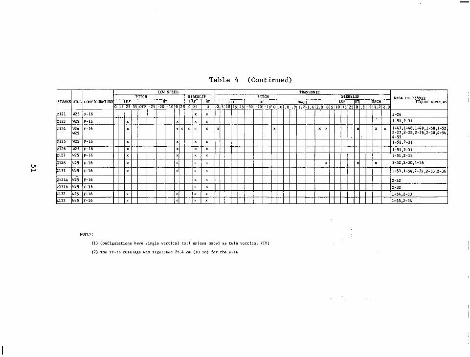
Table 4 (Continued) LOW SPEED TMNSONIC
D Yrrq SlOESLIP PITCH SIDESLIP NAM CR-158922 UT LEF HT LEF HT 1 MACH LEF HT E(ACH FIGURE NlMBERS
I I 101’5125[35TOFFj-25;-20/-lOlO/ 0 p5 0 0/;;:10]15~25 -3O\-20(-10'0 .6].8,.911.2)1.612.0 0~5~1Oj15~25 0 .81.9\1.212.0
121 W25 ~-16 1 ) ) ., ) ] j ) , , ) ) 1 2-26
2123 W25 ~-16 x x x x 1 1 l-51,2-31
I""" . , - _ ^ _
2131 W25 ~-16 x x x x l-53,1-54,2-32,2-33,2-36
Z131A W25 F-16 x x 2-32
21318 W25 F-16 x x 2-32
2132 W25 ~-16 x x x x l-54,2-33
2133 W25 F-16 x x x x l-55.2-34
NOTES :
(1) Configurations have single vertical tail unless noted as twin vertical (TV)
(2) The YF-16 fuselage was stretched 25.4 cm (10 in) for the F-16

bEFF C mEFF m (it)
Ct *EFF
STRAKE m (Et) %,EI
m (Et) Degrees m2 (ft2)
27 .308 1.57 (5.17) 6.78 (22.25) 3.45 (11.33) 77.0 8.06 (86.75)
28 .287 i.37 (4.5) 6.10 (20.0) 3.45 (11.33) 75.0 6.55 (70.49)
z9 .257 1.27 (4.17) 6.30 (20.67) 3.58 (11.76) 77.0 6.28 (67.56)
ZlO .157 .71 (2.33) 5.31 (17.42) 3.76 (12.33) 77.0 3.22 (34.66)
24 .293 I.68 (5.5) 7.19 (23.58) 4.27 (14.0) 73.5 9.60 (103.35)
25 .262 1.68 (5.5) 7.62 (25.0) 5.21 (17.08) 71.0 10.73 (115.50)
216 .192 1.17 (3.83) 7.06 (23.17) 5.13 (16.83) 73.5 7.12 (76.65)
217 .436 2.79 (7.5) 6.48 (21.25) 4.01 (13.17) 65.5 11.99 (129.08) I
218 ' .297 1.68 (5.5) 6.65 (21.83) 4.65 (15.25) 67.5 ~ 9.47 (101.98)
Table 5 STRAKE GEOMETRY FOR CL aS
and IS CALCULATION
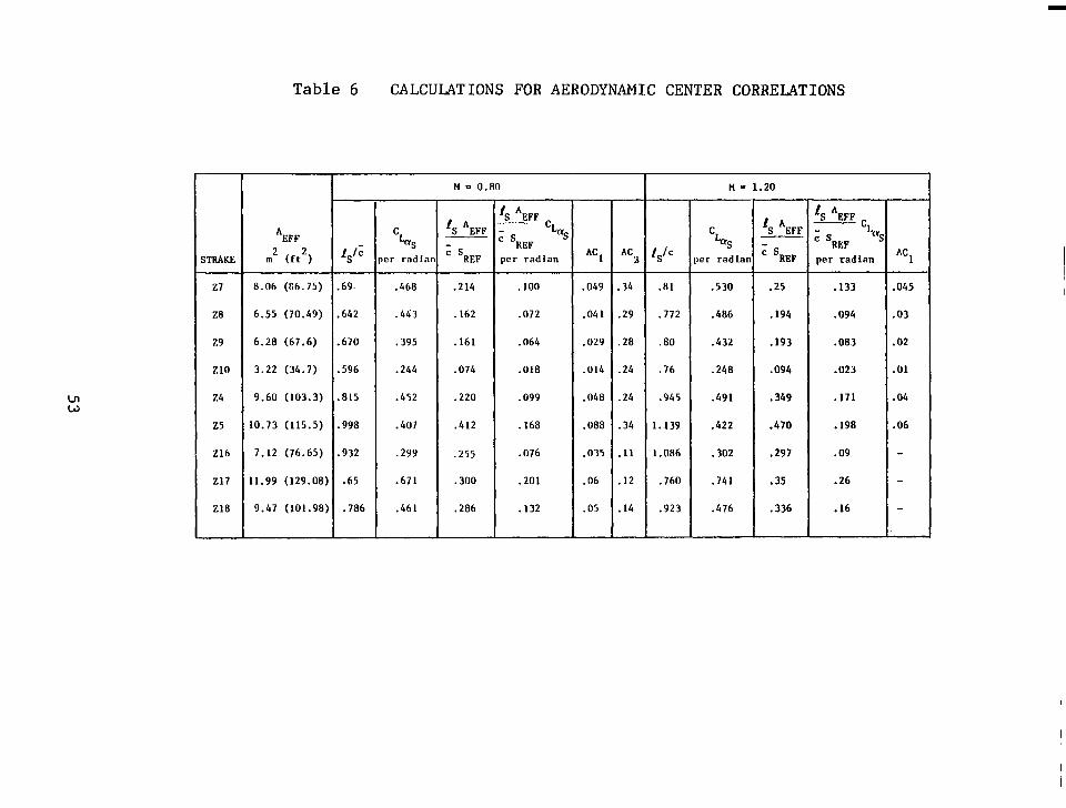
Table 6 CALCULATIONS FOR AERODYNAMIC CENTER CORRELATIONS
I I H = 0.80 I H - 1.20
*EFF
I I -I “5
;TRARE m2 (Et*) ‘S” per rnd
‘S *EFF ‘S *EFF 7 ’ L - cs %
AC AC I a vc ’ ‘REF
REP per radian per radian AC1
28
Z16
8.06 (66.75)
6.55 (70.49)
6.28 (67.6)
3.22 (34.7)
9.60 (103.3)
10.73 (115.5)
7.12 (76.65)
11.99 (129.08)
9.47 (101.98)
.69.
.642
.670
.596
.815
.998
.932
.65
.786
.468
.443
.395
.244
.452
.407
.299
.671
.461
.214 .lOO
.I62 .072
.161 .064
.074 .018
.220 .099
.412 .I68
.255 .076
.300 .201
.286 .132
1 L
.049 .34 .lll .530 .25
.041 .29 .772 .406 .194
.029 .20 .80 .432 .193
.014 .24 .76 .240 .094
.048 .24 .945 .491 .349
.oaa .34 1.139 .422 .470
.035 .ll 1.086 .302 .297
.06 .12 .760 .741 .35
.05 .I4 .923 .476 .336
.133
.094
.083
.023
.171
. 198
.09
.26
.I6
.045
.03
.02
.Ol
8
.04
.06

Figure 1 Sketch of Configuration 785

Figure 2 Sketch of Configuration .786

I n
Figure 3 Sketch of Configuration 401F-2

Figure 4 Sketch of Configuration 401F-5

‘,. I-,, ” .
4 I ,,I ,’ ,I . , .’
Figure 5 Sketch of Configuration 401F-10A

127
254
381
580
WING
w3 W3BB W6 W24 W25
S W - m2(ft2)
26.01 (280.0) 26.10 (280.9) 26.01 (280.0) 27.58 (296.9) 27.87 (300)
AX
3.00 3.05 3.00 3.03 3.00
FS 508 635 762 889 1016 1143 (200) (250) (300) (350) (400) (450)
Figure .6 Wing Planforms

-622.3(245.0) - 99.8(253.5)
-656.6(258.5)
BL 0.0 I
For 27, Z9, ZlOk For 28
I FS 68.6(27.0)
I
BL 108.6 BL 133
BL 1
(42.8) .4(52.5) .47.3(58.0)
4 7oio'
m--e- -1 I -trakes
541.0(213.0)
Figure 7 Configuration 785 and 786 Strakes
WL 269.3(1;6 WL 236.2(93.0)-&
Qs-Jyy I ~_
FS 52.1(20.5)
472.4(186.0)-1
ZlA REF 22 REF Zl REF
Figure 8 Configuration 401F-2 Strakes

WL 237.5(9
381.0(150.0) 29Ll(l15.0)~
&xi& A-A
Figure 9 Configuration 40lF-4 Strakes
0.0
51.1(59.5)

Section thru slot
FS 52.1(20.5) 381.0(150.0) 217, 218, 222, 223
Figure 10 Configuration 401F-5 Strakes

696.2(274.0)
FS 55.4(22.0)
Figure lla
381.d(150.0)
Configuration 401F-10A Strakes
---BL 0.0
- BL 127.0(50.0)

FS w55.9(22.0) y-A --
I 696.0(274.0)
I BL 127.0(50.0)
Section A-A Note: All strakes on maximum half breadth
Figure lib Additional Configuration 401F-10A Strakes

FS
698.5(275.0)
-- LBL 0.0
-7-- 254.0(100.0) -. -- -s / z31 ,‘. L ’ LZ33 -
228, 229 55.9(22.0)
I
BL 127.0(50.0) B.L. 137.2 (54.0)
BL 147.3(58.0)
127.
I 147
O(50.
.3(58
,O) -0)
Figure 12 Configuration 4OlF-16 Strakes
-

3
FS 158.8 62.5)
I
555.8(218.8) 221.0(87.0)
I I I I .I BL 0.0
I \
207.0(81.5)
Wing L.E. 1
Figure 13 Configuration 401F-16E Strakes

521.5(205.3) T
396.7
FS 254.0(100.0)
FS 637.5 (251.0)
Figure 14 YF-16 Strakes with Wing Forward

B.L. 103.4(40.7)
Note: (1) All strakes are in contour except 233A'
and Z33B' which are flat plates. (2) Z33A' and Z33B' have the same planform as
Z33A and Z33B respectively (3) ~331 is Z33C removed Z33C HL (4) Z29d is same as Z33A'
Figure 15a Configuration 401F-16 Small Rotating Strakes

B.L. 80.0(31.5)
FS 427.2(168.2)' I 457.7(180.2) 494.0
233FJ33G HL (194.5)
560.1(220.5+ 233E HL
565.2(222.5)- Z33D HL
(235.3)
Wing L.E.
Figure 15b Additional Configuration 401F-16 Small Rotating Strakes

FS 254.
555.8(218.8)
d-
.(264.2)
Wing L.E.
Figure 16 Large YF-16 Rotating Strakes

WL 217.
77.5(30.5)--l r- 144.0(56.7)
I- 152.1(59.9)
r 198.1(78.0)
1 1 11 1 r254.0(100.0)
FS
7(8
-BL
I (100.0)
152.2 (59.9)
Figure 17 YF-16 Nose and Canard Strakes
.2(54

i YF-16 + 77.5(30.5) Stretch
i
FS 99.6(39.2) 1 176.5(69.5)
I 254Yoo*o) 508.0(200.0)
141.0 I I;?$ n/3';n nl (55.5)
"4.a." \-a.. . -,
670.8(264.1) BL 0.0
272, 268, 264,
275,280 'f / 269, Z70* 265, 266, 271 BL 137.2
(54.0)
271,275 / J
Wing LE-/
266
*Z67-270 are with 113.0 (44.5) Stretch
Figure 18a Strakes for Stretched YF-16

FS
FS
-77.5 131.6 254.0 (-30.:) (100.0)
-33 cl (51i 8)
I I 27"-4. I
I --L&.3 (-9 .O)
/ I
!(llO.O)
*
I -- -- -
273 I
lz74
-Y11-
1
(ZlD) '1 ~~~~~,.7..,..1 1 (36.0)
260.4 ) 149.9(59.0) (102.5:
I I\ 254.0(100.0) 670 81264 1)‘. .
l
YF-16 + 77.5(30.5) Stretch
Figure 18b Additional Strakes for Stretched YF-16

FS 228.6, -240.54(94.7) (90 .O) v-254.0(100.0)
-292.1(115.0) 673.Ot265.0) 330.2(130.0) 444.5(175.0)
I BL 0.0
Note : 2107=2104 cut to FS 292.1(115.0) = 762.0 (300.0) z108=z105 cut to FS 330.2(130.0) z109=2103 cut to FS 330.2(130.0)
Figure 19 F-16 Forebody Strakes

-.-. __ ____.______________.~~.~..
FS -67.3 (-26.5)
I 29.2(11.5)
(-20.5)
-25.h
Note: All strakes are parallel to the grobe except 2117 which is bent down 5 ,i.e., 2%' below waterline
Figure 20a F-16 Nose Strakes
76

Note: 2128 same as 2124 but rotated up So about FS -12.7(-5.0)
< --_ 0 --- 7-
-- z124,2128
FS -54.'1(-21.3)
-12.7
--------4B.L. 0.0
B.L. 31.2
16.0
44.5i17.5)
I
B.L
(12.3)
BL 0.0
. 31.2 (12.3)
Figure 20b Additional F-16 Nose Strakes
77

Nose
-12,7 (-5.0)
31.8 44.5 (12.5) (17.5)
BL 0.0
(12.0)
n-
Nose probe
B.L. 0.0
B.L. 13.2C5.2)
-12.7 0-O (-5.0)
/
E
I
L ____c____-
-33v (-13.0)
Figure 20~ Additional F-16 Nose Strakes
78

BL
FS
0.0
‘N12 FS 2:7-2
WL 211.5 (83.25)
Figure 21 Nose Shapes Tested on the F-16

00 0
SYM TEST RUN LEF TEF HT MACH CONFIG -A- 1831 1630 0 0 0.80 OFF --&- 1931 171 0 0 0 0.80 27
-FE-. 1931 163 0 0 0 0.90 28
-+- 1931 196 0 0 0 0.80 29
-+ 1831 188 0 e 0 0.80 210
-5 0 5 FINGLEI’OF FIT&K, D?GREES*’
30 te.4 t0.2 PITC~eMOM.-0fOEF.-0’4
Figure 22a Lift Effects of a Family of Delta Planform Forebody Strakes on Configuration 785

/ SYM TEST RUN LEF TEF HT nRCH CONF I G “:: .‘. :. ._ _ ,.. _ _ _
..3 ~ . . . . !.;I ; :.; : / ..: : i .:..:..: _ _. :.A r _: :. :. : .: + :; __ : i : :::. h 1831 163 0 0 0 0.80
OFF . . . . . ..i ; _ :._ _ + :.
f.f.“. L k .f .:‘I’
:.. r :. _ : I. . . + : _,i j, ---+I+-- 1931 171 0 0 0 0.80 t7 ..i.*’ 1. - _ i ._. _._
.; .j 2 ..i.;..i .,. ;.-..‘: L. j. :. ..i..& .f, ..: .i._..:.. _..:. :..:. _ ,_,. .._ ,..
5.: i :: . ..i. ..i.L --EEt- 1931 183 0 0 0
.i.J..i i .i j’; : ,j / 1. : .,^: I.;;:.::;:. :::; 0.80 28 :_ ..:_i __.;: .;:t. .._i . * 1931 *cJe
..( .+..;. .:_. ..:+ ., :,_ .~ + :.
0 Q :..:.+ .j. .; .I Li.
0 0. 80 jr? ..;..+ . :... :.. .I..,....i.. , 3 .: j, i j _. : ;./ 4..
~ --#-- 1931 I88 0 0 0 0.80 ..i..i..i z10 :! ;..i..:...f & ;..i. .f.
:.;.j. i::. -;.. ,i(i ,!ii .i;: :I:; ‘(i: is:.. :_./
..&i..- . ...,; i :. ;,i ;_:, +“’ (.:,; :: :’ :. i j ,: .:, i _.., _,
0.0 0.1 0.2 0.3 0.4 0.5 DRFIGO$oEF. 0.7 0.8 0.9 1.B 1.1
Figure 22b Drag Effects of a Family of Delta Planform Forebody Strakes on Configuration 785

SYM TEST RUN LEF TEF HT MACH CONFIC
-A-3630 1040 0 0 0.80 263 -e-3630 1530 0 0 0.80 264
-El+ 363Q 251 (1 0 I? 0.90 265
-+- 3630 255 0 0 0 0.80 266
-ik-~ 3630 149 0 0 0 0.90 271
5 FlNGLE%F QTT%CK, D?GREESz5 38
t0.4 t0.2 PI TC!iOMOM .-‘;OEF . -“’
Figure 23a Lift Effects of a Family of Ogee Planform Forebody Strakes on a Stretched YF-16

00 W
0.9 0.1 0.2 0.3 0.4 0.5 0.6
DRFlG COEF. 0’7
0.8 0.9 1.0 1.1
Figure' 23b Drag Effects of a Family of Ogee Planform Forebody Strakes on a Stretched YF-16

-++- 6772 15 .25 : 6 0 0.20 -2124
10 20 30 ‘4 L* 53 60 +9.‘1 l .2 (4 0 -9.2 +?.(I
FlNGLE OF FITTFICK, DEGREES PITCH MOM. COEF.
Figure 24 Effects of a Nose Strake on the F-16 Lift
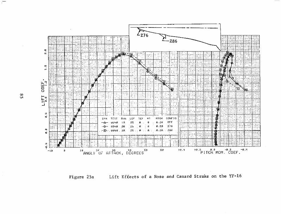
1 -1
Figure 25a Lift Effects of a Nose and Canard Strake on the YF-16
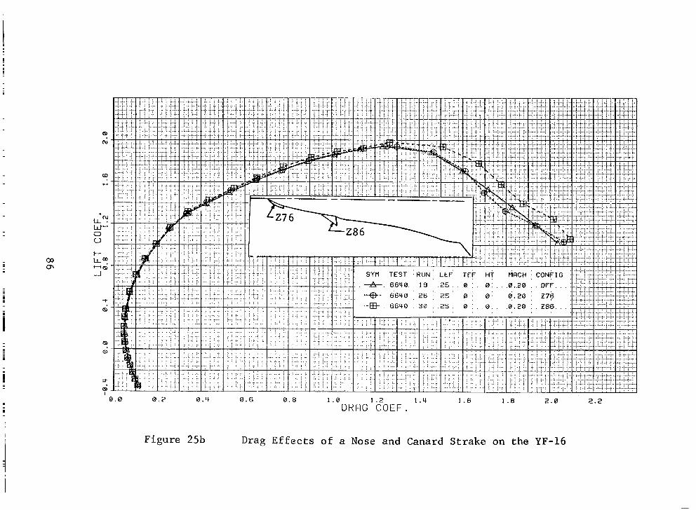
co cn
0.0 0.4 0.6 0.8 1.0 1.2 1.4 1.6 1.8 2.0 2 .2
ORPIG COEF.
Figure 25b Drag Effects of a Nose and Canard Strake on the YF-16

-5 0 5 RNGLE’?IF QT&K, D?GREES*’
30 t0.4 t0.2 PI TCi?MOM ;‘tfOEF . -“’
Figure 26a Lift Effects of a Leading-Edge Flap on Configuration 401F-5 with No Strake

co 00
‘N LL.
LLI”
E
+ m
0.0 0.1 0.2 0.3 0.4 O.SDRRGO.&, 0.7 0.8 0.9 1.0 1.1
Figure 26b Drag Effects of a Leading-Edge Flap on Configuration 401F-5 with No Strake

SYPl TEST RUN LEF TEF HT IIRCH CONFIG -A-10324370 0 0 0.80 OFF -+- 1832 471 0 0 0 8.80 24 -EB-- 1932 r(83 10 0 0 0.80 24
--+. 1932 577 15 0 0 0.80 24
-Q- 1932 588 25 0 0 0.80 24
-5 0
’ FINGLE?lF FIT&K, D?GREES2’ 30 ce.4 l4.2
PI TCh’MOM .-??OEF . -0.4
Figure 27a Lift Effects of a Leading-Edge Flap on Configuration 401F-5 with a Forebody Strake

m ni
‘N LL. W” 0 0
+ m:
Q
m
zt
i 0.0 0.1 0.2 0.3 0.4 0'5DRQG0&EF. 0.7 0.8
Figure 27b Drag Effect of a Leading-Edge Flap on Configuration 401F-5 with a Forebody Strake

2.4 M=O. 80
HT=o 2.0
1.6 A/ CL
In envelope - 24 Strake-o
Strake-off envelope
Strake off, LEF=O
-0.4 -5 0 5 10 15 20 25 30
OL -Degrees
Figure 28a Effect of a Forebody Strake on the Envelope Lift Curve

ul N
2.4
2.0
1.6
CL
1.2
0.8
0.4
0
-0.4 i 0
M=0.80 HT=O
24 Strake-on envelope
/ Strake-off envelope
Strake off, LEF=O
1
.1 .2 .3 .4 .5 .6 .7 .8 .9
CD
1.0 1.1
Figure 28b Effect of a Forebody Strake on the Envelope Drag Polar

SYM TEST RUN LEF TEF HT HFlCH CONFIG
e 1931 1630 0 0 0.80 OFF
----fp-- 1931 171 0 0 0 0.80 Z7 --j-j+- 1931 183 Q 0 0 0.80 28
0.06 0.08 0.10 0.12 0.14 0.16 0.18 DRflG COEF.
Figure 29 Effects of a Family of Delta Planfonn Forebody Strakez on the Low-Lift Drag at .80 Mach Number

:.: .I .: .:. :. .j. :.T! .:!.
.i.;..d ..r... ..: i , .i. : : :
: : : .i L.A.,. .L.i...i...i
::.: :. ./ .+f..(. i-i.
:: :; . . . .
i : : .?. ,... !‘.. i.l.,i.,;
. ..l.i i ( j ;.j.
L .I j. I:. .;.. I ; ,.;
; .; : : ; .: .-/ .;
;.i : j : / .j /
; i, j..i. ,/ ,.j,.;. i
.+ ._: _ ;. .: ..:. .;
i .L. 1.j.: : : : j : : j :“.’
:::: i: .L .I _ ,: : .:., .,
: :
Figure 30
0.02
SYM TEST RUN LEF TEF HT MFlCH CONFI(
+ 1931 161 0 0 0 1.20 OFF
----+&--- 1931 168 0 0 0 1.20 27
--+I+- .1931 177 0 0 0 1.20 Z8
0.84 0.06 0.08 0.10 0.12 0.14 0.16 DRF)G
0.18 COEF.
Effects of a Family of Delta Planform Forebody Strakes on the Low-Lift Drag at 1.20 Mach Number
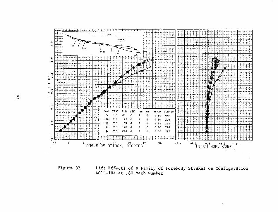
SYM TEST RUN LEF TEF HT WICH CONFIG
lsl0 I3 0 0.30 225
-+- 2131 176 0 ‘J 0 0.80 226
-.#-- 2131 200 0 B 0 0.80 227
-5 0 ’ RNGLE$F RT%CK, D?GREES25
30 t0.4 b0.2 PITCteMOM ?tfOEF .-“’
Figure 31 Lift Effects of a Family of Forebody Strakes on Configuration 401F-10A at .80 Mach Number

-5 0 ’ FINGL&F RT&K, D?GREES2’
30 t0.4 l-0.2 PI TCk’MOM .-‘fOEF .
-0.4
Figure 32 Lift Effects of a Family of Forebody Strakes on Configuration 401F-10A at .90 Mach Number

’ nNGLE’:F AT&K, DFGREES 25 30 te.4 t0.2
PITCb’MOM -8.2 -0.4 . COEF.
Figure 33a Effects of Forebody-Strake Blending on Lift

Q
0.00 0.02 0.04 0.06 0.08 0.10 0.12 DRFlG COEF.
0.16 0.18
Figure 33b Effects of Forebody-Strake Blending on Drag

.6
.5
.4
.3
.2
.1
, , , : I . : I
_ cLa Based on total planform !_ :',j" : ::.. ; ,, j ],, j ,; j
D- ..__ :._.:_ . ..!. -. S i+SO . . . . . !.. : I
I L : ,! .i : ‘! I
,j ‘ibi ._ :.:w.i:j.l....., i
.I .:.; . . :,,. j..i j : : .: .iL: ,;.:,. :
I
I ..;-,::j,,
j -- .;. 1.0---y-7-= , ‘. i Reproduced from Reference 3
1 2 3 4 b IV
Figure 34
BTanALEi
Calculation Chart for Prediction of Non-Linear Lift of Double-Delta Planforms at Subsonic Speeds.

Srn TEST RUN LEE TEF HT nfiih CO~JFIG .*. 1931 163 0 0 0 0.9t OFF
- 1931 171 0 0 0 0.20 z7 - 1931 183 0 0 0 0.m zs
---. 1931 196 0 0 0 0.80 z9 - 1931 188 0 0 0 0.sc Z!Q
w-9 BFlSELINE RUN
\...” ,,.....
,--28 0 /H--..-_rd z9
5 10 15 20 25 30 a- Degrees
Figure 35 Evaluation of WINSTAN Lift Prediction Technique
100

/ Strake on
CL
Figure 36
/ -
-.-
/ /
/
ACL / /
t / /
/ %
/
/ / /
/ Shift / / I /'
1 /
/. /
/ /
/
/' Strake /
/ /
a break
off
Modified WINSTAN Lift Prediction Technique
101

-... .- -. -. . . _. - . ._ . .
.3
ACL
.2
.1
0
SYM TEST RUN LEF TEF HT MRCH CONFIG
m)L* 1931 163 0 0 0 0.&O OFF - 1931 171 0 0 a 0.EC 27 -I 1931 183 0 0 0 0.03 ze _e--. 1931 196 0 0 0 0.60 F9 ---.- 1931 188 0 0 0 0.80 ZIQ
L=* SRSELINE RUN
Prediction
Figure 37
a-Degrees
Evaluation of Modified WINSTAN Lift Prediction Technique
102

P 0 LJ
r A
Section A-A
Figure 38 Definition of Effective Strake Area for a Simple Wing Body Configuration
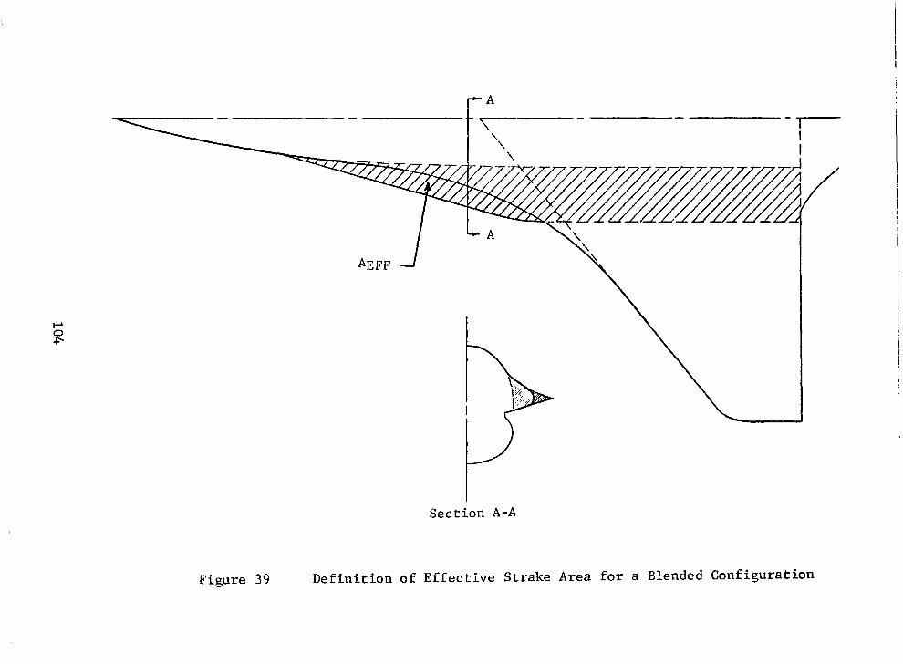
I- A
Figure 39
Section A-A
Definition of Effective Strake Area for a Blended Configuration

. . . ..,..I.. .i . . . . .._. :. I..:. . . . . . . . ..i..l.. ‘*----- 1931 183 0 0 0 0.&O ze
,..+. . ..i .j..i..:. /.!.!_!...! ..!.!. +. .---. 1931 196 0 0 0 0.80 ts
: .: 1. I.. .i . . . . . / i :. i..i.. .,,_,,,_,,._ 1931 188 0 0 0 0.EO Zl? ..,i .j, :, ,.‘; ./ / i !. I ! j ‘....a..! *** ERSELINE RUN
I .._..: i,, i.:.:.: :;.:.I __ _. ._ I : . . . - -
../.i.. ,.‘_/ , .:! . :.I ,.... :;:
,.
I <! I I. SYH TEST RUN LEF TEF HT MRCH .Ti’NFii:
: .:. : T. : *** 173095 5 0 0 0.ao SF= : . ,..: ., ..- 1931 202 5 0 0 0.EC zi
I -** BRSELINE RUN I -5 0 5
f!NGLE”OF F;T;‘FCK , I%GREES~~ 33
Figure 40 Incremental Strake Lift for a Family of Delta Planform Strakes on Configuration 785
105

i * ,../ ,;<: >,;. SYII TEST RUN LEF TEF Hi MfiCil CCNFIG : .:. :.. 1. _ : ,/ .i *** Q.t?C CiF ._i,./ .-.. i. :..f I /.i. : i.j 19324370 0 0
,. <, : .y ; : i : ..:: :..f i .I i - 1932 471 0 0 0 Q.E,’ z4 ._.____ 1932 477 0
es!!8 BRSELItE :UN ” SC: ‘S -.
m: I .._____ 1932 +94 10 0 0 8.52
*W BRSELiNE RUN -5 0 5
RNG&F RT;SRCK, I%GREES~’ 3C
Figure 41 Incremental Strake Lift for a Delta and Gothic Planform Strake on Configuration 4OlF-5
106

-5
MECH CS::fiC 0.sc GFi 0.22 ZIS 0.8G ZIE
0.EO ?I7
3.60 Zii‘
0 5
FlNGLEl’OF
SYM TEST RUN LEF TEF HT *** 1932 428 10 0 0
- 1932 603 I0 0 0
------ 1932 597 10 0 0
. . _ -. 1932 594 10 0 0
* 1932 600 10 0 0 *** BRSELINE RUN
RT%CK , I%C-REE<~ 3c
Figure 42 Incremental Strake Lift for a Family of Ogee Planform Strakes on Configuration 401F-5
107

; ..’ :. : / a’ : ,..,f j ! : ..!’ .: : : :,.,,’ : .: .,.. ‘,
iE
/’ a:<.; ; i., _:: ,f: ^..i ; ; .!!, .l... A i ._.j :
SYM TEST RUN LEF TEF HT MGCH iCKF:c-
10 0 0 0.El: Z?i
NE RUN
,._.. . . . . . . m..’ j +7-
-5 a 5 FlNGLE”OF d&K , %GREE?
30
Figure 43 Incremental Strake Lift for a Family of Ogee Planform Strakes on Configuration 401F-10A
108

.8
ACL
.6 SREF AEFF
.4
.2
0
ACL
ACL
.8
. 6 SREF AEFF
.4
.2
0
.4 SREF AEFF
.2
0 4 8 12 16 20 24 28 a -Degrees
Sym Strake AEFF m2(ft2) 0 27 8.25 (88.8)
Y 0 Z8 6.58 (70.8) 0 z9 6.17 (66.4) V ZlO 3.36 (36.2j
I : , : : ; : ; ; ; ; ; ; : 0 4 8 12 16 20 24 28
8 12 16 24 or-Degrees
Figure 44 Incremental Strake-Lift for a Family of Delta PlanformStrakes on Configuration 785 (Based on AEFF)
109

-- ---- .--..-. -- ........ ._.__-- ........... ......... ._.__ .. . ... -.-. .......... ....
ACL
.8 M-0.80 LEF-0
sR6, AEFF i
.4 -.
.2 -'
0 .;;; 0 4 8 12 16 20 24
a- Degrees
.8 1
LEF=lOO
.6
SREF AcL AEFF
.4
.2
0 0 8 12 16 20 24
a- Degrees
Figure 45 Incremental Strake Lift for a Delta and Gothic Planform Strakeon Configuration 401F-5 (Based on AEFF)
110
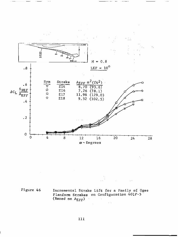
ACL
.8 LEF = 10'
. 6 SREF AEFF
.4
.2
0
%m St.rake v
AEFF m2(ft2) 214 8.70
0 (83.6)
Z16 7.26 (78.1) 0 217 0 218
t : e . : ; : : ; : , ,,
0 , : ; : !
4 ; ; .
8 12 16 20 24 28 a- Degrees
Figure 46 Incremental Strake Lift for a Family of Ogee Planform Strakes on Configura.tion 401F;5
-(Based on AEFF)
111

.8
t
Sym .6 v
Strake
SREF 0 224
ACL - I
225 AEFF o 226
M=0.80 LEF=O
AEFF m2(ft2) 6.80 (73.2)
: : : ! : : : : i : ; : : 0 4 8 12 16 20 24 28
a-Degrees
0 4 8 12 16 20 24 28 a-Degrees
a-Degrees
Figure 47 Incremental Strake Lift for a Family of Ogee Planform Strakes on Configuration 401F-10A (Based on AEFF)
112

I ----
Current definition
probable area for large span strakes
Figure 48 Definition of Effective Strake Area for Large Span Strakes

ACL
M ='0.80. I
24, CONF.
0 0 4 8 12 16 20 24
a-Degrees
.8
. 6
SREF dCLAG
.2
0
LEF = 10'
z4,zs CONF. 401F-5
Z14.216.217.218-
..- ‘._ c
224,225,226.227 . v.,F?.TZT CONF. 4blF-iOA.
(~-Degrees Figure 49 Effects of Configuration and Strake Geometry
on Incremental Lift
114

I --_-__ 36302510 0 0 0.83
.---. 3630 255 0 0 0 0.88
..-.. . ..- 36301V90 0 0 0.80
**1 BFlSELINE RUN
Figure 50
!’
;;
/.
j.. ).
.i. ,i.
.i
.:.
.>.
Z63 --.. T-o+ Z65
Z66 171
.:1 .,: :’ ‘.::
a.’ : I. .,_
I ; ._ ::.
. . . .:.
,I 8”
.
I ..m-m. - 3630 259 0 0 0 0.80 ‘93 HI* BRSELINE RUN
-5 0 5 RNGLE*‘OF FIT%CK, %GREE:’ 30
Incremental Strake Lift for a Family of Ogee Planform Strakes on the Stretched YF-16
115

-- ‘.
‘\ \ ‘.
SREF "L AAEFF M=O.8
LEF=O
.Sym - v
6. 0 0 0
4.. :
Strake AAEFF m2(ft2) 264 .14 (1.50) 265 .86 (9.24) Z66 1.39 (14.93) 271 .63 (6.82) 275 .21 (2.31)
-2 t, 4 8 12 16 20 24 28 a-Degrees
Figure 51 Incremental Strake Lift for a Family of Ogee Planform Strakes on the Stretched YF-16 (Based on AAEFF)
116

1.5
1.0 ACD
ACL tan @+i)
Figure 52 Incremental Drag Correlation for Forebody Strakes
Sym 0
M=O.8 a LEF=O 0
cl Cl-l A
L +2% PCLtal (a + i>
'-%. --
0 D 0
0
Strake 24 25 27 28 z9 ZlO 224 225 226 227
a-Degrees

Q
s
S,‘,, -fi’;T R,,N ‘LEF TEF ,,T : MQC,, C:ONF,,;:
(1 1R 20 3R FlNGLE OF QTTGCt!, &KEES6@
68 to .4 +3.2 4.2 PITCH @.(li f$Yl. COEF .-‘.’
Figure 53 Pitch Effects of a Family of Ogee Planform Forebody Strakes on the YF-16 + 30.5 Stretch

Figure 54 Pitch Effects of Forebody Strake Forward Extent on the YF-16 + 30.5 Stretch

64 :25 0 0 0.28
t(c.q M.2 Q . 0 -8.2 43.14 PITCH MOM. COEF.
Figure 55 Pitch Effects of a Family of Ogee Planform Forebody Strakes on the YF-16 + 44.5 Stretch

j:. .::. . . .
./.: .I::. .I:. ..}*
-+t+ 6620 II6
Figure 56 Effect of Horizontal Tail Deflection on the Pitch Effects of Ogee Planfom Forebody Strakes, YF-16 + 30.5 Stretch
.

0 STEUKES 27 - ZlO 0 STRAKES 24 & 25 A STRAKES 216 - 218
approximatecyrange Q! < loo
.4 -
.3 - lsAEFF cL
%EF as
.2 - A / lx
.l - 2 P-6
A5 OV I I I I I
0 .02 .04 .06 .08 .lO
AA.C 1
Figure 57 Linear Region Stability Shift Due to Forebody Strakes, M = 0.80
-- . ._ .
122

I approximatearange a<100
0 STRAKES 27 - ZlO 0 STRAKES 24 & Z5
0 , 0’ /
/o 0 c... 1 L I I -. 1 -- I
0 .Ol .02 .03 .04 .05
AAC 1
.
Figure 58 Linear Region Stability Shift Due to Forebody Strakes, M= 1.20
123

.5
.4
esAEFi3
%EF l 2
.l
0
Apprgximate CY range 10 5as25O LEF FUSELAGE
SYM.STRAKE (DEG) CON-FIG. 0 24 0 401F-5 a 24 10 401F-5
15 401F-5 25 401F-5
0 401F-5 /
/ t % 10 0 401F-5
785
n z9 0 785 0 ZlO 0 785 : 210 216 10 5 401F-5 785
CT 217 10 401F-5 A 218 10 401F-5
/ /
@/ d
785 I 1 I I I
0 .l .2 .3 .4 .5
AA C 2
,
Figure 59 High Angle of Attack Stability Shift Due to Forebody Strakes, M = 0.80
124

SYtl TEST RUN LEF TEF HT ALPHA tiFlCH CONFIG -a+ 6772 12 25 0 0 31.5 0.20 2126
-a- 6772 5’+ 25 0 0 31.6 0.20 +Z12Y -B)-, 6772 13 25 0 0 35.6 0.20 2120 -+- 6772 55 25 0 B 35.7 0.20 tz12L( -+- 6772 1’4 25 0 @ 40.4 0.20 El20
-#-- 6772 56 25 0 0 Y0.U 0.20 +212q
-5 FlNGLE :F SID%SLIP,“DEGRE&
Figure 60 Sideslip Characteristics of Nose Strake 2124 on the F-16
125

M = 0.2
Referen e conditions: 27.87 m 5 (300 ft2)
. 35 c
Y x u
oc
Figure 61 Effect of Nose Strake Length on Directional Stability
126

-. .I . . . ..,_,. _.::..
SYH TEST RUN LEF TEF HT RLPHR MRCH CONFIG .i$+j.. : j..j -+r 6771 20 25 0 0 31 . 5 0. 20 zl 1 0 ::;yj:j’: ::;::; .;::q 1’; .i. ;
” ” *-e- 6771 ‘+7 25 0 0 31.6 0.20 P112 ..i:,i.i...i,; .;. i.i .i. I : / /. .,i.:; /. :..;..j -@- 6771 2’+ 25 0 0 31 *5 0.20 z113 .i * i.i...; i..q:; ;;:j
-10 -5 FlNGLE ?IF SIDESLIP,
10 DEGRE&
20
Figure 62 Effect of Nose StrakeShape on the F-16 Sideslip Characteristics
127

-5 QNGLE :F SID:SLIP,“DEGRE&
Figure 63 Effect of Nose Strake Inclination on the F-16 Sideslip Characteristics
128

Figure
+ 6620 39 25
B --@-- 6620 35 25
+ -f$b 6620 ‘+3 25
-*+- 6620 43 25
8?
+ -15 -10 -5
RNGLE ‘OF SIDk-LIP,lODEGRE& 20
64 Sideslip Characteristics of a Family of Ogee Planform Forebody Strakes, YF-16 + 30.5 Stretch
129

-15 -10
Figure 65 Sideslip Forebody
-5 QNGLE ‘OF S&SLIP,
10 DEGRE&
20
Characteristics of a Family of Ogee Planform Strakes, YF-16 + 44.5 Stretch
130

i! Reference l-l
conditions : :: 27.87 m2(300 ft.q
TEST RUN LEF TEF HT
-5 FlNGLE $F SIDb3LIP,10DEGREl%
Figure 66 Sideslip Characteristics of Nose Strake ZlOO on the F-16 at 0.9 Mach Number
131

SWI TEST RUN LEF TEF HT FILPHR HRCH OONF 1 G
-A- 1730 18 0 0 0 25.7 0.80 OFF e-e-, 1931 164 0 0 0 21.7 0.80 OFF --E-- 1831 17q 0 0 0 2y.3 0.80 z7
-+-- 1931 182 0 0 0 23.9 0.80 Z8 .-. # -- 1931 195 0 0 0 22.6 0.80 ZS .,(.
+i.. i : ..: ,,.j ; .:...i .i
../ I ..:. ,.. .+ .~ ..:..j:
..i.i.I i. ..,......, . . . ./. _.. ::. -.--Erru _.l.i ;...+\.; ..+.;,i..i .:.j j.; ! .;.;.. i.i.i..i .: ) i.;
. . . ,.!. !.I ! ! ..l , .I ! 4, v * ..i I, . ? ,. . . . . . . ...! .,, .I ! 5. : 2 !“1 ..i., ;.i. .:i : : ,.A..8 ,..:.: I., l,:‘.:Ii~-..li‘:~,:-.:,--:
-5 FlNGLE :F SIDtSLIP. “DEGRE&
20
Figure 67 Sideslip Characteristics of a Family of Delta Planform Forebody Strakes on Configuration 785, LEF = 0
132

Figure 68
-10 -5 QNGLE ‘OF SID~SLIP,‘ODEGRE&
20
Sideslip Characteristics of Delta Planform Forebogy Strakes 27 and ZlO on Configuration 785, LEF = 15
133

-10 -5 FlNGLE @OF SIDhLIP,
10 DEGRE&
2Q
Figure 69 Sideslip Characteristics of Gothic Planform Forebody Strake 25 on Configuration 401F-5, LEF = 0
134

SYM TEST RUN LEF TEF HT FILPHR WRCH CONFIG + 1932 ~31 10 0 0 25.2 0.80 OFF .-*- 1932 458 10 0 0 25. 1 0. 80 z4 43+- 1932 455 10 0 0 25.6 0.80 ~5
-10 -5 FlNGLE ?IF SIDkSLIP,
10 DEGREE
20
Figure 70 Sideslip Characteristics of Delta and Gothic Planfon Forebody Strakes 24 and 25 on Configuration 401F-5, LEF = 10'
135

Q: I
-15 -5 FINGLE :F SIDhLIP,
10 DEGRE;:
20
Figure 71 Sideslip Characteristics of a Family of Ogee Planform Forebody Strakes on Configuration 401F-5
136

m
EVI TEST RUN LEF TEF HT FlLPHR HFlCH CONFIG .--.: : j 1: .: ._ 7:. !.
-&- “~‘T .,., ~. ..i.: : 2131 35 25 0 0 25.0 0.80 OFF .f._..:. ~ .._.. :. /. ; .j i,
hi+- 2131 111 25 0 0 2,+.,+ 0.80 z.24 -w.
::~.i;; ;;:;:::: ‘.I,, .:..: ./ / j j.j.i.1 : , ; 11 j 1 : 1 2131 157 25 0 0 25. 1 0. 80 ~25 ,.. : 1
--+- 2131 173 25 0 0 2rC.9 0.80 Z26 -+-- 2131 207 25 0 0 25.2 O.sO ~27
r,-
:; T r : I.. : , ., _, 1 ^ , : _ : , : _ : ,,, _ : : , I , _ :,., , I : , , I I
-15 -10 -5 FlNGLE ‘OF SID~SLIP,lODEGRE~
28
Figure 72 Sideslip Characteristics of a Family of Ogee Planform Forebody Strakes on Configuration 401F-10A
137

-10 -5 RNGLE :F SIDbLIP,
10 DEGRE&
20
Figure 73 Sideslip Characteristics of a Family of Ogee Planform Forebody Strakes on Configuration 401F-16
138

AERODYNAMIC CHARACTERISTICS OF FOREBODY AND NOSE
J.N. Ralston
Aeronautics and Space Administration
Langley Technical Monitor: James M. Luckring Final Report
16. Abrtnct
The YF-16 and F-16 developmental wind tunnel test program has been reviewed and all force data pertinent to the design of forebody and nose strakes extracted. Volume I contains geometrical descriptions general comments, representative data, and the initial efforts toward the development of design guides for the application of strakes to future aircraft. Volume II, NASA CR-158922, contains a complete set of these data without analysis.
17. Key Words LSuggested by Authorkl) 16. Oisrr~butmn Statement
Forebody Strakes,Nose Strakes, High-Angle-of-Attack
Unlimited - Unclassified Vortex Lift, Aerodynamics
Subject Category 02
19. Security CIaoif. (of this report1 20. Security ClassiF. lof this pa@ 21. No. of Pages 22. Rice’
Unclassified Unclassified 142 $7.25
* For sale by the National TechnIcal InformatIon Service. Springfield. Vlrglnla 22161 NASA-Langley, 1979