AERODYNAMIC FEATURES AS AUXILIARY … · AERODYNAMIC FEATURES AS AUXILIARY ARCHITECTURE 297...
10
N. Gu, S. Watanabe, H. Erhan, M. Hank Haeusler, W. Huang, R. Sosa (eds.), Rethinking Comprehensive Design: Speculative Counterculture, Proceedings of the 19th International Conference on Computer- Aided Architectural Design Research in Asia CAADRIA 2014, 295–304. © 2014, The Association for Computer-Aided Architectural Design Research in Asia (CAADRIA), Hong Kong AERODYNAMIC FEATURES AS AUXILIARY ARCHITECTURE Design and analysis of protection regions for wind discomfort in a local urban context, using CFD simulations RAFAEL MOYA 1 , SIMON WATKINS 2 , YAN DING 3 , JANE BURRY 4 and MARK BURRY 5 1,2,3,4,5 RMIT University, Melbourne, Australia 1 [email protected], 2 [email protected], 3 [email protected], 4 [email protected], 5 [email protected] Abstract. This paper presents the experimental study of aerodynamics phenomena in built environments, focused on explorations of envi- ronmental wind flow near buildings, pedestrian wind comfort issues and methods of mitigation of wind speed. In addition, it is an over- view of an aerodynamic analysis with CFD software for a hypothet- ical urban shelter design, based on aerodynamic features. The aim is to evaluate the feature’s performance to control wind flow in protec- tion regions for pedestrians. Keywords. Urban aerodynamics; CFD simulation; wind discomfort. 1. Background The habitability and comfort in a building’s external space, where the at- mospheric dynamics (wind) are affected by the urban context generating wind phenomena around buildings (Figure 1), has received a lot of attention in recent years by researchers (Stathopoulos, 2011). In many cases, the pub- lic space requires mitigation methods for local wind issues at the ground lev- el. Even though existing options to change or ameliorate pedestrian wind conditions have been documented in the literature (Cochran, 2004), methods of control and mitigation of local wind discomfort in pedestrian areas are difficult to be implemented, because of the inflexibilities associated with the built environment. In general, it has promoted the use of vegetable screens as
Transcript of AERODYNAMIC FEATURES AS AUXILIARY … · AERODYNAMIC FEATURES AS AUXILIARY ARCHITECTURE 297...

N. Gu, S. Watanabe, H. Erhan, M. Hank Haeusler, W. Huang, R. Sosa (eds.), Rethinking Comprehensive Design: Speculative Counterculture, Proceedings of the 19th International Conference on Computer-Aided Architectural Design Research in Asia CAADRIA 2014, 295–304. © 2014, The Association for Computer-Aided Architectural Design Research in Asia (CAADRIA), Hong Kong
AERODYNAMIC FEATURES AS AUXILIARY ARCHITECTURE
Design and analysis of protection regions for wind discomfort in a local urban context, using CFD simulations
RAFAEL MOYA1, SIMON WATKINS2, YAN DING3, JANE BURRY4 and MARK BURRY5 1,2,3,4,5 RMIT University, Melbourne, Australia 1 [email protected], 2 [email protected], 3 [email protected], 4 [email protected], 5 [email protected]
Abstract. This paper presents the experimental study of aerodynamics phenomena in built environments, focused on explorations of envi-ronmental wind flow near buildings, pedestrian wind comfort issues and methods of mitigation of wind speed. In addition, it is an over-view of an aerodynamic analysis with CFD software for a hypothet-ical urban shelter design, based on aerodynamic features. The aim is to evaluate the feature’s performance to control wind flow in protec-tion regions for pedestrians.
Keywords. Urban aerodynamics; CFD simulation; wind discomfort.
1. Background
The habitability and comfort in a building’s external space, where the at-mospheric dynamics (wind) are affected by the urban context generating wind phenomena around buildings (Figure 1), has received a lot of attention in recent years by researchers (Stathopoulos, 2011). In many cases, the pub-lic space requires mitigation methods for local wind issues at the ground lev-el. Even though existing options to change or ameliorate pedestrian wind conditions have been documented in the literature (Cochran, 2004), methods of control and mitigation of local wind discomfort in pedestrian areas are difficult to be implemented, because of the inflexibilities associated with the built environment. In general, it has promoted the use of vegetable screens as
296 R. MOYA, S. WATKINS, Y. DING, J. BURRY AND M. BURRY
a main classic element of mitigation and wind control, thanks to their posi-tive performance and good aesthetic condition. However, the question about how to improve the outdoor environments for pedestrian comfort remains as a field of exploration of technical solutions and new designs of architectural elements.
Figure 1. Turbulence around buildings (Designing the Dynamic Workshop, 2011).
Porous membranes and permeable structures are being explored with new
morphologic approaches for designers to provide conditions of comfort. Be-cause of their possible architectural applications such as auxiliary elements for buildings to deal with the wind conditions, Michael Hensel (2012) has called them as a "Supplementary Architecture".
However, the control of wind phenomena and the improvement of re-gions of comfort provided by architectural solutions need an additional ap-proach. The aerodynamic studies of Jacques Gandemer about wind comfort, windbreaks and their aerodynamic features are relevant to determine ways of manipulation for wind condition and wind mitigation methods. His experi-ments of particular interest are about porous screens and aerodynamic fea-tures. These features allow changes in the wind flow pattern produced by po-rous forms and permeable materials when they are strategically integrated and associated to work as windbreaks.
This research proposes the convergence of the auxiliary architectural el-ements and the aerodynamic features, as a strategy of design to be used for the mitigation of wind issues in outdoor environments near buildings.
2. Research aims
The first objective of this research is focused on an aerodynamic analysis of wind effects produced by aerodynamic features in a shelter prototype. These aerodynamic features are based on the studies of Jacques Gandemer about artificial porous screens (Gandemer, 1981). Gandemer explored different

AERODYNAMIC FEATURES AS AUXILIARY ARCHITECTURE 297
configurations of fences used as windbreaks. These studies, realised with wind tunnel experiments, evaluated several possible barrier designs and the protection factor produced, respectively. After several tests, screens with a 20-30% porosity were found to have the best performance (Gandemer, 1979). However, Gandemer also found that some auxiliary features produce par-ticular aerodynamic effects when these are integrated to the porous screens, increasing the region of protection at the leeward side of the barrier.
Four of these features are defined as more significant for further experi-mental models: graduated pattern of porosity, auxiliary curve deflector, dou-ble slot of acceleration, and parallel screens (Figure 2). Thus, these can be studied as potential design components of architectural prototypes with more complex forms or in contexts with different wind phenomena (like local wind in a built environment).
Figure 2. Gandemer’s experiments of windbreaks and aerodynamic features. Left: deflector
and porous screen. Right parallel screens (taken from Gandemer, 1979).
The relevance of these the features for wind control is verified with aero-
dynamic experiments with the intention to use them to create wind deflec-tions in substitution of physical region boundaries for an urban wind shelter (tram stop). These wind deflections increase the protection region of a wind-break, to be referred to as wind thresholds in this paper.
2. Experimental methodology
The methodology is based on empirical evaluations and experiments on a hypothetical project of shelter for a tram stop of the city. These experiments involve simulation and analysis using Ansys CFD (Computational Fluid Dy-namics) software to verify the location of the eddy regions and protection areas generated by the wind mitigation feature. These experiments with digi-tal technology link parameters of aerodynamic phenomena in urban context, local wind issues and aerodynamic feature performance. Additionally, in the first stage, to simplify and to facilitate the further experiments: all models
298 R. MOYA, S. WATKINS, Y. DING, J. BURRY AND M. BURRY
studied and tested are simple geometries representing individual screens or roofs, where their condition as porous surfaces is more significant and easy to evaluate.
1.2. URBAN WIND PHENOMENON
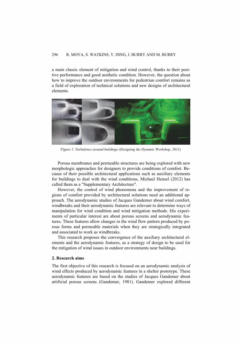
To facilitate the aerodynamic experiments and analysis, the Authors selected a specific urban wind phenomenon presents in an urban context: a phenome-non caused by the seasonal prevalent wind in the Melbourne City (North to South). The high wind speed along a narrow street (Figure 3), known as the Channel Effect (Gandemer et al., 1978), can cause discomfort to the pedes-trians in the region.
Figure 3. CFD test. Visualisation of channel effect phenomenon.
The space previously described involves two areas: the street space and a
tram stop site. The street runs from South to North and has 30m width and includes a tram track of the Public transport system. This tram stop is an area of 4.5m width and 69m length on the west sidewalk. It considers urban furni-ture and a roof to protect the pedestrians while they are waiting for the pub-lic transport.
The statistics shows a trend of prevalent winds from North to South dur-ing the second half of the year (Bureau of M, 2013). In a windy day, with wind blowing from the north, the channel effect is produced along the street, with more intensity around a tram stop area near the street’s intersection. Here, there is no protection from natural foliage of trees and the wind flows at ground level with high velocity along the sidewalk and the tram stop (probably intensified by corners of facades) causing discomfort on pedestri-ans that are waiting for public transport (Figure 4).

AERODYNAMIC FEATURES AS AUXILIARY ARCHITECTURE 299
Figure 4. Fluctuation of wind speed in the tram stops area.
1.3. STANDARDIZATION OF PARAMETERS FOR CFD SIMULA-TIONS
Because of the limitation of instruments, data and time, it is not possible to replicate the real wind conditions of the place for the purpose of these exper-iments. To simplify the simulations, standard conditions are used as parame-ters. Thus, for the digital simulation, the urban context is represented as a simple and regular geometry of a channel. The standard of wind discomfort used is a speed of 5m/s at 1.5m height (head level) (Wisse, 1988). Wind flows only in one direction (main characteristic of a channel effect). The ac-celeration from corners is omitted, but other wind conditions are considered such us the atmospheric boundary layer based on the power law equation (Aynsley et al., 1977). The turbulence intensity is fixed to a low level (5%).
The Fluid Domain is where the channel effect is recreated. This has 30m width (similar to the distance between opposite facades), 16m height and a 69m length. The bottom face represents the ground, the front and back sides are street facades. A low grade of roughness is given to these surfaces to simulate the friction of facades and ground.
The second digital mesh is the tram-stop domain with 10m height, 15m width and 46m length which represents a part of tram stop region. This small domain has more density of the digital mesh for a more detailed simulation of the wind around the model: the wind effects at the windward side, lee-ward side and along the wake region (Figure 5).

300 R. MOYA, S. WATKINS, Y. DING, J. BURRY AND M. BURRY
Figure 5.Left: Fluid Domain and tram stop domain. Right: digital mesh.
3. Tram stop design
The design process involves the definition of a group of regions of protec-tion based on the observation of conditions of use for pedestrians, and a group of CFD simulations to define the installation of each aerodynamic fea-ture. In addition, the first design of the tram stop is based on a literal inter-pretation of the windbreak shapes and aerodynamic features studied by Gandemer. They are adapted as physical installations to produce these wind thresholds and protection regions.
The definitions of protection regions and the regions consider 3 basic programs in the site. The first one is a shelter area with a roof for pedestrians who wait for the tram. The second program is an area in front of a private building entrance. Finally, there is the main entrance to the same building with more traffic of people. These three spaces overlap the activities and functions of a private building with a public space. Therefore, the general plan of the tram stop has 4 regions (Figure 6).
Figure 6. 3D model of the tram stop. Simple geometries represent the street and installations.
The installations are designed to generate wind thresholds. These thresh-
olds can be understood as vertical wind deflections to replace a physical bar-

AERODYNAMIC FEATURES AS AUXILIARY ARCHITECTURE 301
rier. To achieve this, these elements must create a layer of low pressure above the tram stop area. With the association of three basic elements: a po-rous screen with 20% porosity, a horizontal curved surface as a deflector with a double slot system and a convex deflector above the barrier, which provides a region of protection for each area of the tram stop. The main re-quirement is to keep a low vertical porous barrier (1.6m height); the protec-tion must be generated by the wind threshold effect.
3. Preliminary results
The CFD simulation of these aerodynamic features shows in the first instal-lation a strong vertical deflection (wind threshold) and protection region of 3.5m height. This means a double height of the barrier itself. This vertical deflection is defined as a free shear layer that separates the free-stream flow from the recirculating region, increasing the protection area behind the barri-er. The effect can be controlled by manipulating the position of the deflector elements (concave and horizontal deflector). With this wind threshold, it is possible to reduce the height of the vertical porous barrier to not interrupt the view of the pedestrians (Figure 7). Additionally, based on this first simula-tion it is possible to define the distances for the position of each screen and deflector.
Figure 7. Left: highly vertical deflection as wind wall to increase height of wake region.
Right: Aerodynamic effect: wind velocity contours from CFD simulation.
Moreover, a second aerodynamic simulation tested the effects produced
for a roof profile for the tram stop. This roof is installed with a curvature to catch the threshold projected to the leeward side and deflect it up over the upper surface of the roof. With a ventilation gap at the top of the curvature it is possible to reduce the acceleration of the wind in this shelter. However, an acceleration of the wind at the outlet area of the roof region is detected. To avoid this, a second porous barrier under the roof is installed. These parallel barriers are other of the aerodynamic features mentioned. The CFD visuali-

302 R. MOYA, S. WATKINS, Y. DING, J. BURRY AND M. BURRY
sation shows the whole protection region generated (Figure 8). With the sec-ond porous screen installed, an additional phenomenon is produced between both regions: the second screen produces a change in the direction of the wind, moving back to the inlet region and produces a neutralisation of in-coming wind. This effect is in the first part of the roof region.
Figure 8. Top: areas of wind acceleration under the curved roof. Middle: aerodynamic fea-
tures are included to change the wind flow pattern. Bottom: the roof is adapted to facilitate a vertical deflection of the wind.

AERODYNAMIC FEATURES AS AUXILIARY ARCHITECTURE 303
Also, the second porous screen extends the protection area of the first po-rous screen increasing the protection region along the tram stop area (Figure 9, left).
Figure 9. CFD simulation: wind velocity vector plot. Left: extension of the protection region with a second porous barrier. Right: adaptation of the roof for the vertical wind deflection.
Finally, this visualisation shows that it was necessary to include a new
design for the second part of the roof profile. By splitting the roof in three parts this avoided the acceleration of wind at the outlet area.
4. Conclusion
The aerodynamic phenomena around buildings and wind issues in pedestrian areas provide an opportunity for experimentation with the design of new mit-igation systems through architectural explorations and digital technologies for visualisation.
This paper presents an additional approach to improve the control of pro-tection in pedestrian areas: the aerodynamic features of windbreaks produce changes in the wind flow pattern that increase their region of protection. Likewise, these features can be used to improve the mitigation system de-signs of wind issues in outdoor environments.
The preliminary results of these experiments and simulations for a hypo-thetical tram stop design suggest that the aerodynamic features give a control of protection regions in a tram stop. They produce wind effects called wind thresholds and can be used as an effective passive method of mitigation of wind speed. This means to increase the protection region, avoid wind flow distortions and reduce the size of the physical barriers.
On the other hand, the visualisation and analysis of these aerodynamic phenomena and the effects of the aerodynamic features require technological
304 R. MOYA, S. WATKINS, Y. DING, J. BURRY AND M. BURRY
tools of simulation to improve the feedback between the designer and the comprehension of aerodynamic phenomena. CFD analysis is a tool with a relevant role in the analysis of cases and development of design strategies.
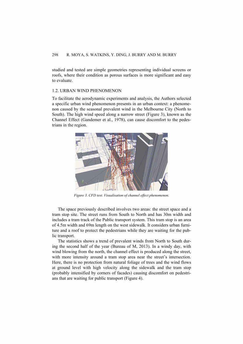
The next stage of this research will explore the adaptation of these aero-dynamic features with other architectural alternatives, such as designs based on porous membranes (Figure 10).
Figure 10. Propositions of membranes for screens and deflectors.
References
Aynsley, R. M., Melbourne, W. H. & Vickery, B. J. 1977. Architectural aerodynamics, London, Applied Science Publishers.
Web, Bureau of M, A. G. 2013. "Climate statistics for Australian locations". Australia. Available:<http://www.bom.gov.au/climate/averages/tables/cw_086071_All.shtml> (accessed September 2013).
Cochran, L. 2004. Design Features to Change and/or Ameliorate Pedestrian Wind Conditions. Structures Congress 2004. Nashville, Tennessee, United States: American Society of Civil Engineers.
Gandemer, J. 1979. Wind Shelters. Journal of Industrial Aerodynamics, 4, 371-389. Gandemer, J. 1981. The aerodynamic characteristics of windbreaks, resulting in empirical
design rules. Journal of Wind Engineering and Industrial Aerodynamics, 7, 15-36. Gandemer, J., Centre scientifique et technique du, b. Đ. & United, S. I. f. A., Technology
1978. Discomfort due to wind near buildings: aerodynamic concepts, Washington, D.C., U.S. Dept. of Commerce, National Bureau of Standards.
Hensel, M. U. 2012. Design Innovation for the Built Environment: Research by Design and the Renovation of Practice, London/GB, Taylor & Francis Ltd.
Stathopoulos, T. 2011. Introduction to Environmental Aerodynamics. Environmental Wind Engineering and Design of Wind Energy Structures, 531, 3-30.
Wisse, J. A. 1988. A Philosophy for Teaching Wind in the Built Environment. Energy and Buildings, 11, 157-161.