AERIAL WORK PLATFORM - Support Unlimited, Inc. Home · of the aerial work platform from the engine...
18
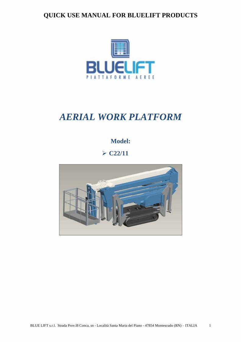
QUICK USE MANUAL FOR BLUELIFT PRODUCTS BLUE LIFT s.r.l. Strada Prov.l8 Conca, sn - Località Santa Maria del Piano - 47854 Montescudo (RN) – ITALIA 1 AERIAL WORK PLATFORM Model: C22/11
Transcript of AERIAL WORK PLATFORM - Support Unlimited, Inc. Home · of the aerial work platform from the engine...
QUICK USE MANUAL FOR BLUELIFT PRODUCTS
BLUE LIFT s.r.l. Strada Prov.l8 Conca, sn - Località Santa Maria del Piano - 47854 Montescudo (RN) – ITALIA 1
AERIAL WORK PLATFORM
Model:
� C22/11
QUICK USE MANUAL FOR BLUELIFT PRODUCTS
BLUE LIFT s.r.l. Strada Prov.l8 Conca, sn - Località Santa Maria del Piano - 47854 Montescudo (RN) – ITALIA 2
This QUICK USE MANUAL has been written with the purpose of making the first approach simpler to the Bluelift products. In this manual Bluelift S.r.l. are exemplified with images and short message the different phases of use of the aerial work platform from the engine starting to the stabilization and lifting. It is important remember thah this manual is not substitutive of the “USE AND MAINTENANCE MANUAL” issued with the aerial work platform. ONLY USE THE MACHINE AFTER HAVING CAREFULLY READ TH E DESCRIPTION OF THE
CONTROLS AND YOU KNOW ALL THE FUNCTIONS. HOWEVER IT IS OBLIGATORY READ AND UNDERSTAND THE “U SE AND MAINTENANCE
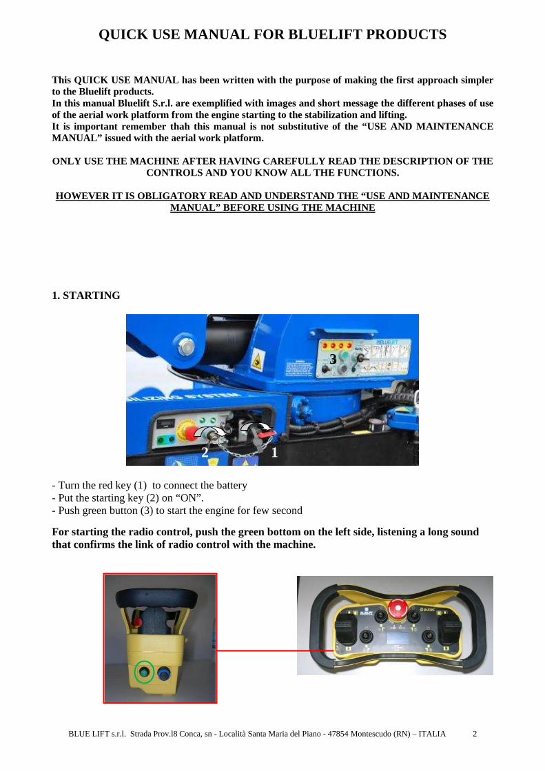
MANUAL” BEFORE USING THE MACHINE 1. STARTING
- Turn the red key (1) to connect the battery - Put the starting key (2) on “ON”. - Push green button (3) to start the engine for few second
For starting the radio control, push the green bottom on the left side, listening a long sound that confirms the link of radio control with the machine.
3 2 1

QUICK USE MANUAL FOR BLUELIFT PRODUCTS
BLUE LIFT s.r.l. Strada Prov.l8 Conca, sn - Località Santa Maria del Piano - 47854 Montescudo (RN) – ITALIA 3
Green led: good level of radio control battery Red Led: lower level, change the battery!
2. OPERATION WITH COMBUSTION ENGINE
If the aerial platform has an Honda iGX440 15HP engine, it is enough turn the engine ignition key on position 1 (see picture) and push the green button (3) which is on the GENERAL START-UP CONTROL PANEL.
3. MOVING the MOBIL ELEVATING WORK PLATFORM (TRANSL ATION)
The “key selector for controlling the boom lift from remote control/basket” (4) has to be down on the position with carriage imagine. On the display it is present the below pictograph.
This symbol indicates that the radio control is not connected with the machine. Push again the green bottom on the left side.
This symbol indicates that machine turret is in the center position. It is possible to close the machine for the transport
Level of radio control’s battery
4

QUICK USE MANUAL FOR BLUELIFT PRODUCTS
BLUE LIFT s.r.l. Strada Prov.l8 Conca, sn - Località Santa Maria del Piano - 47854 Montescudo (RN) – ITALIA 4
Operate the two levers from the control wire backwards and forwards simultaneously to obtain translation movement in one direction or the other; by operating the levers individually, the machine may be steered – this steering may be accentuated by carrying out a counter-rotation of the other track. The C22/11 is fitted with the TRACK DOUBLE SPEED SYSTEM: after 5 second that you are moving the track in forward or backward direction, the system starts the double speed on the track, only if the machine is on a plane floor. When the inclination of the floor changes (ex. on a ramp or on a slope) or the operator turns the platform left or right direction, automatically the system reduces the speed.
!!! NOTE: Operate at safety distance from the machine !!!
4. WIDTH ADJUST CRAWLER SYSTEM The model C22/11 is supplied standard with a CRAWLER WIDTH ADJUSTING SYSTEM. It is possible to modify the width of the crawler moving from a minimum width of 0,90 m to a maximum width of 1,2 m.
When you see this pictograph on the display, the functions available by the radio control are: - driving - manual/automatic stabilization of platform - track width adjusting system - selection of petrol or electric engine - start/stop engine
QUICK USE MANUAL FOR BLUELIFT PRODUCTS
BLUE LIFT s.r.l. Strada Prov.l8 Conca, sn - Località Santa Maria del Piano - 47854 Montescudo (RN) – ITALIA 5
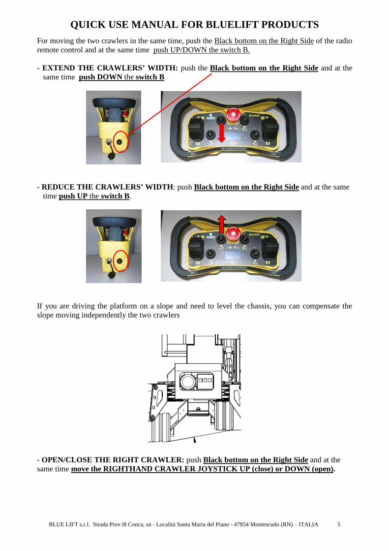
For moving the two crawlers in the same time, push the Black bottom on the Right Side of the radio remote control and at the same time push UP/DOWN the switch B. - EXTEND THE CRAWLERS’ WIDTH: push the Black bottom on the Right Side and at the
same time push DOWN the switch B
- REDUCE THE CRAWLERS’ WIDTH : push Black bottom on the Right Side and at the same
time push UP the switch B.
If you are driving the platform on a slope and need to level the chassis, you can compensate the slope moving independently the two crawlers
- OPEN/CLOSE THE RIGHT CRAWLER: push Black bottom on the Right Side and at the same time move the RIGHTHAND CRAWLER JOYSTICK UP (close) or DOWN (open).
QUICK USE MANUAL FOR BLUELIFT PRODUCTS
BLUE LIFT s.r.l. Strada Prov.l8 Conca, sn - Località Santa Maria del Piano - 47854 Montescudo (RN) – ITALIA 6
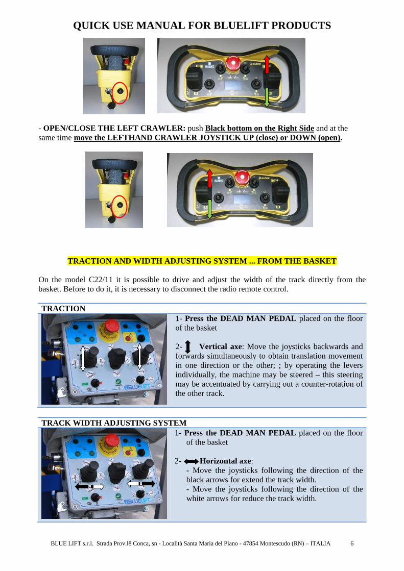
- OPEN/CLOSE THE LEFT CRAWLER: push Black bottom on the Right Side and at the same time move the LEFTHAND CRAWLER JOYSTICK UP (close) or DOWN (open).
TRACTION AND WIDTH ADJUSTING SYSTEM ... FROM THE BA SKET On the model C22/11 it is possible to drive and adjust the width of the track directly from the basket. Before to do it, it is necessary to disconnect the radio remote control. TRACTION
1- Press the DEAD MAN PEDAL placed on the floor of the basket 2- Vertical axe: Move the joysticks backwards and forwards simultaneously to obtain translation movement in one direction or the other; ; by operating the levers individually, the machine may be steered – this steering may be accentuated by carrying out a counter-rotation of the other track.
TRACK WIDTH ADJUSTING SYSTEM
1- Press the DEAD MAN PEDAL placed on the floor of the basket
2- Horizontal axe:
- Move the joysticks following the direction of the black arrows for extend the track width. - Move the joysticks following the direction of the white arrows for reduce the track width.

QUICK USE MANUAL FOR BLUELIFT PRODUCTS
BLUE LIFT s.r.l. Strada Prov.l8 Conca, sn - Località Santa Maria del Piano - 47854 Montescudo (RN) – ITALIA 7
6. MACHINE STABILIZATION A) Open the stabilizer and Select the setting area
1. Move up the second part of the outrigger
2. Fix it with the specific pivot
3. Select the setting area:
IMPORTANT: Fix each outrigger with its pivot and be sure to push down completely the pivot. IMPORTANT: Before operating the machine, ensure that the ground can withstand the weight of the platform itself, the people and the equipment. The platform must be placed on a surface that is flat, solid, compact and firm. Do not place the stabilizers on manhole or on slippery surfaces e.g. wet marble floors. CAUTION! In function of the field’s camping factor it is possible that machine slides on slope also if it is settled correctly. On the model C22/11 there are 3 possible setting areas:
MAX. AREA All outriggers in position A Setting area:4 m x 4,36 m MED. AREA All outriggers in position B Setting area: 3 m x 5,2 m MIN. AREA All outriggers in position C Setting area: 2 m x 5,67 m
A B C C B
A
QUICK USE MANUAL FOR BLUELIFT PRODUCTS
BLUE LIFT s.r.l. Strada Prov.l8 Conca, sn - Località Santa Maria del Piano - 47854 Montescudo (RN) – ITALIA 8
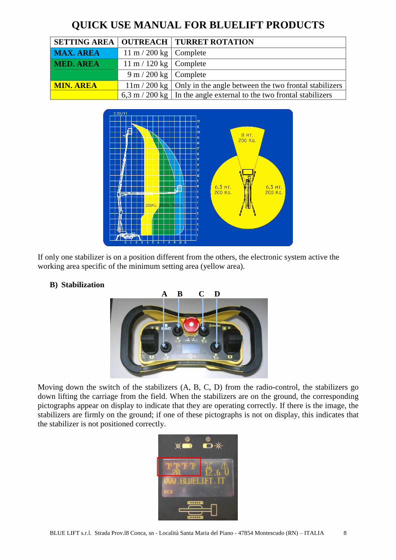
SETTING AREA OUTREACH TURRET ROTATION MAX. AREA 11 m / 200 kg Complete MED. AREA 11 m / 120 kg Complete
9 m / 200 kg Complete MIN. AREA 11m / 200 kg Only in the angle between the two frontal stabilizers 6,3 m / 200 kg In the angle external to the two frontal stabilizers
If only one stabilizer is on a position different from the others, the electronic system active the working area specific of the minimum setting area (yellow area).
B) Stabilization A B C D
Moving down the switch of the stabilizers (A, B, C, D) from the radio-control, the stabilizers go down lifting the carriage from the field. When the stabilizers are on the ground, the corresponding pictographs appear on display to indicate that they are operating correctly. If there is the image, the stabilizers are firmly on the ground; if one of these pictographs is not on display, this indicates that the stabilizer is not positioned correctly.

QUICK USE MANUAL FOR BLUELIFT PRODUCTS
BLUE LIFT s.r.l. Strada Prov.l8 Conca, sn - Località Santa Maria del Piano - 47854 Montescudo (RN) – ITALIA 9
There are three phases to stabilize the machine correctly: 1. Lower the four stabilizers towards the ground 2. Simultaneously lift the two stabilizers that are on the downhill side 3. Simultaneously lift the two stabilizers on the opposite side until the machine is level
N.B: Verify the right levelling of machine looking the optical level placed on the turret.
It is important lift the crawlers from the field also for few centimetres
SELF STABILIZING - DESTABILIZING SYSTEM - Self Stabilization: push the Black bottom on the Right Side and at the same time push DOWN
the switch A
When the automatic stabilization is activated, the position "0"led green flashes and the buzzer sends a continuous sound up until the moment in which the system calculates the good levelling position. In this situation, the position "0" led green is fixed and the buzzer sends an intermittent sound. Continue the same procedure to reach the wanted levelling and height from field of carriage.
NOTE: Verify the right levelling of machine looking the optical level placed on the turret. If the position “0” led flashes and the alarm is active, the machine is not levelled.
- Self Destabilization: push Black bottom on the Right Side and at the same time push UP the
switch A, until you have closed the outriggers completely.

QUICK USE MANUAL FOR BLUELIFT PRODUCTS
BLUE LIFT s.r.l. Strada Prov.l8 Conca, sn - Località Santa Maria del Piano - 47854 Montescudo (RN) – ITALIA 10
SELF STABILIZING - DESTABILIZING SYSTEM FROM THE BA SKET
1- Not link the radio remote control 2- Without pushing the Dead Man Pedal, move the middle joystick
• DOWN for STABILIZING AUTOMATICALLY THE PLATFORM
• UP for DESTABILIZING AUTOMATICALLY THE PLATFORM
N.B: Verify the right levelling of machine looking the
optical level placed on the turret.
7. LIFTING MOVEMENTS A) … from PLATFORM CONTROL BOX
After having positioned and levelled the machine, on platform control box the four leds (see the previous picture) are lighted showing that all stabilizers touch the field . To be able to effect any movement, you have to press the DEAD MAN PEDAL (picture below).
A reminder that it is necessary to press the DEAD-MAN PEDAL on the cage floor to be able to operate the various controls; if this pedal is held down for one minute without any movements being carried out, it must be released and pressed again to be able to carry out movements – this is to guarantee safety against accidental movements. For lifting the machine it is enough to move one of the tree joysticks. Below, you can read the different functions of each joystick.
Emergency red button for blocking the machine’s movements at any time
Start and Stop Engine
Selector of the electric engine
QUICK USE MANUAL FOR BLUELIFT PRODUCTS
BLUE LIFT s.r.l. Strada Prov.l8 Conca, sn - Località Santa Maria del Piano - 47854 Montescudo (RN) – ITALIA 11
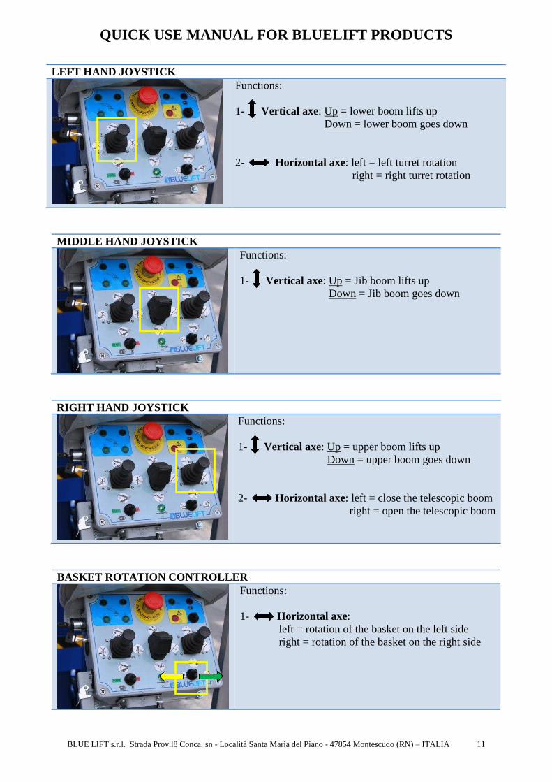
LEFT HAND JOYSTICK
Functions: 1- Vertical axe: Up = lower boom lifts up Down = lower boom goes down 2- Horizontal axe: left = left turret rotation right = right turret rotation
MIDDLE HAND JOYSTICK
Functions: 1- Vertical axe: Up = Jib boom lifts up Down = Jib boom goes down
RIGHT HAND JOYSTICK
Functions: 1- Vertical axe: Up = upper boom lifts up Down = upper boom goes down 2- Horizontal axe: left = close the telescopic boom right = open the telescopic boom
BASKET ROTATION CONTROLLER
Functions: 1- Horizontal axe: left = rotation of the basket on the left side right = rotation of the basket on the right side

QUICK USE MANUAL FOR BLUELIFT PRODUCTS
BLUE LIFT s.r.l. Strada Prov.l8 Conca, sn - Località Santa Maria del Piano - 47854 Montescudo (RN) – ITALIA 12
KEY SWITCH for CORRECT THE BASKET LEVELLING
Functions: 1- when the platform is stabilized and without lifting any booms, you can control manually the basket levelling. Procedure: - turn the key selector - move up or down the jib joystick for levelling the basket
LED CENTER POSITION
Before closing the machine for the transport, it is necessary to put the turret in the centre position. The green “OK” led is on.
When you turn the turret and you arrive closed to the centre position, the software stops automatically the rotation for few second, the yellow “OK” led is on and you can closed the machine for the transport. Otherwise if you want to continue the rotation, move the joystick rightward or leftward.
When the turret is in centre position, on the display of the radio control is showed the below pictograph:
The initial recommended sequence is as follows:
I. Jib lifting II. Scissor lifting
III. Main boom lifting IV. Outreach of telescopic boom V. Rotation
B) …from REMOTE CONTROL On each Bluelift model, it is possible transfer the lifting movement controls from the basket control box to the remote control only for emergency procedure.

QUICK USE MANUAL FOR BLUELIFT PRODUCTS
BLUE LIFT s.r.l. Strada Prov.l8 Conca, sn - Località Santa Maria del Piano - 47854 Montescudo (RN) – ITALIA 13
1. SPRING TYPE KEY SELECTOR FOR CONTROLLING THE BOOM LIFT FROM REMOTE CONTROL/BASKET: gives the possibility to select which part of machine you want to control. When the key is on undercarriage imagine, it is possible move the truck and stabilizers from the radio control; when you turn up the key on the platform imagine, it is possible move the platform from the radio control. 2. PICTOGRAMS ABOUT BOOM LIFT MOVEMENT FROM REMOTE CONTROL
Procedure: - Turn up the key selector 1 for transfer the lifting movement controls on the radio-control - Operate the switch A, B, C, D from the remote control backwards and forwards for making the needed movement. The pictograms (2) show which switch is linked to each movement.
Switch Movement A Pantograph boom B Main boom C Turret rotation D Outreach of telescopic boom C + D Jib
NOTE: THE SPEED OF MOVEMENTS BY RADIO CONTROL IS LO W.
- Turn up again the key selector (1) for returning the lifting movements controls from the radio control to the basket box. In this way, it is possible to control again the stabilizers and truck movements from the radio control. IMPORTANT: if you switch off the machine or push the emergency red bottom, when you restart again the platform, automatically the software actives the control of movements from the basket.
When you see this pictograph on the display, it is possible to control the lifting movement directly from the radio control for emergency procedure.
2
1
QUICK USE MANUAL FOR BLUELIFT PRODUCTS
BLUE LIFT s.r.l. Strada Prov.l8 Conca, sn - Località Santa Maria del Piano - 47854 Montescudo (RN) – ITALIA 14
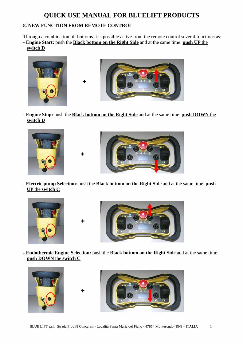
8. NEW FUNCTION FROM REMOTE CONTROL Through a combination of bottoms it is possible active from the remote control several functions as: - Engine Start: push the Black bottom on the Right Side and at the same time push UP the
switch D
- Engine Stop: push the Black bottom on the Right Side and at the same time push DOWN the
switch D
- Electric pump Selection: push the Black bottom on the Right Side and at the same time push
UP the switch C
- Endothermic Engine Selection: push the Black bottom on the Right Side and at the same time
push DOWN the switch C
+
+
+
+
QUICK USE MANUAL FOR BLUELIFT PRODUCTS
BLUE LIFT s.r.l. Strada Prov.l8 Conca, sn - Località Santa Maria del Piano - 47854 Montescudo (RN) – ITALIA 15
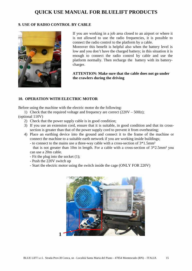
9. USE OF RADIO CONTROL BY CABLE
If you are working in a job area closed to an airport or where it is not allowed to use the radio frequencies, it is possible to connect the radio control to the platform by a cable. Moreover this benefit is helpful also when the battery level is low and you don’t have the charged battery; in this situation it is enough to connect the radio control by cable and use the platform normally. Then recharge the battery with its battery-charger. ATTENTION: Make sure that the cable does not go under the crawlers during the driving
10. OPERATION WITH ELECTRIC MOTOR Before using the machine with the electric motor do the following:
1) Check that the required voltage and frequency are correct (220V – 50Hz); (optional 110V)
2) Check that the power supply cable is in good condition; 3) If you use an extension cord, ensure that it is suitable, in good condition and that its cross-
section is greater than that of the power supply cord to prevent it from overheating; 4) Place an earthing device into the ground and connect it to the frame of the machine or
connect the machine to a suitable earth network if you are working inside buildings; - to connect to the mains use a three-way cable with a cross-section of 3*1.5mm² that is not greater than 10m in length. For a cable with a cross-section of 3*2.5mm² you can use a 20m cable. - Fit the plug into the socket (1); - Push the 220V switch up - Start the electric motor using the switch inside the cage (ONLY FOR 220V)
1

QUICK USE MANUAL FOR BLUELIFT PRODUCTS
BLUE LIFT s.r.l. Strada Prov.l8 Conca, sn - Località Santa Maria del Piano - 47854 Montescudo (RN) – ITALIA 16
When the 220V led flashes, the battery has a value lower 12 V and it is necessary to recharge the battery.
If the 220V plug is fitted into the socket, turn the red key (1) down to connect the battery, put the starting key (2) on OFF to recharge the battery.
This led is light up when the 220V plug is fitted into the socket
Start and Stop Engine
Move for selecting the electric engine
2 1
QUICK USE MANUAL FOR BLUELIFT PRODUCTS
BLUE LIFT s.r.l. Strada Prov.l8 Conca, sn - Località Santa Maria del Piano - 47854 Montescudo (RN) – ITALIA 17
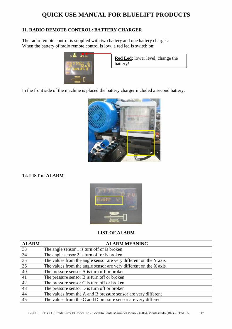
11. RADIO REMOTE CONTROL: BATTERY CHARGER The radio remote control is supplied with two battery and one battery charger. When the battery of radio remote control is low, a red led is switch on:
In the front side of the machine is placed the battery charger included a second battery:
12. LIST of ALARM
LIST OF ALARM
ALARM ALARM MEANING 33 The angle sensor 1 is turn off or is broken 34 The angle sensor 2 is turn off or is broken 35 The values from the angle sensor are very different on the Y axis 36 The values from the angle sensor are very different on the X axis 40 The pressure sensor A is turn off or broken 41 The pressure sensor B is turn off or broken 42 The pressure sensor C is turn off or broken 43 The pressure sensor D is turn off or broken 44 The values from the A and B pressure sensor are very different 45 The values from the C and D pressure sensor are very different
Red Led: lower level, change the battery!

QUICK USE MANUAL FOR BLUELIFT PRODUCTS
BLUE LIFT s.r.l. Strada Prov.l8 Conca, sn - Località Santa Maria del Piano - 47854 Montescudo (RN) – ITALIA 18
46 The lower boom joystick on the basket is not centered when the machine is turned on 47 The upper boom joystick on the basket is not centered when the machine is turned on 48 The rotation joystick on the basket is not centered when the machine is turned on 49 The telescopic boom joystick on the basket is not centered when the machine is turned
on 50 The jib joystick on the basket is not centered when the machine is turned on 51 Error on the connection of the card in the basket 52 One or more stabilizers pivot are not inserted with the stabilizers on the ground 53 The telescopic chain is broken 54 The machine has an inclination greater than 5 degrees on the Y axis
FAQ: - You cannot move the stabilizers:
1- The machine is not in the centre position (the position “0” led is off) 2- the “key selector for controlling the boom lift from remote control/basket” is active; turn the key up. 3- you have not closed completely the booms: the micro to read the boom closing is not active.
- You cannot move the crawlers:
1- verify that all stabilizers don’t touch the field 2- verify on remote control that there isn’t any led (A, B, C, D) on with stabilizer up (micro blocked)
- You cannot active the lifting movements from the basket:
1- the “key selector for controlling the boom lift from remote control/basket” is active; turn the key up. 2- the emergency cover is open: micro is active. 3- the pedal in the basket is not connected.