AERATION BLOWER SYSTEMS INDUSTRIAL VACUUM & …...INDUSTRIAL VACUUM & BLOWER SYSTEMS 17 12 20...
36
The Magazine for ENERGY EFFICIENCY in Blower and Vacuum Systems September 2017 24 Dense Phase Pneumatic Conveying kW CO 2 INDUSTRIAL VACUUM & BLOWER SYSTEMS 17 Danish Furniture Producer Kvist Switches Plants to Centralized Vacuum Systems 20 Custom Blower and Air Knife Bin Drying Solution Reduces Packager Labor Hours AERATION BLOWER SYSTEMS 12 Aeration Blower Control Efficiency
Transcript of AERATION BLOWER SYSTEMS INDUSTRIAL VACUUM & …...INDUSTRIAL VACUUM & BLOWER SYSTEMS 17 12 20...

The Magazine for ENERGY EFFICIENCY in Blower and Vacuum Systems
Sept
embe
r 20
17
24 Den
se Ph
ase P
neum
atic C
onve
ying
kW
CO2
INDUSTRIAL VACUUM & BLOWER SYSTEMS
17 Danish Furniture Producer Kvist Switches Plants to Centralized Vacuum Systems
20 Custom Blower and Air Knife Bin Drying Solution Reduces Packager Labor Hours
AERATION BLOWER SYSTEMS
12 Aeration Blower Control Efficiency

Don’t Settle for Less than the Best
Energy is the single highest operating cost in a wastewater treatment plant and 60% of a plant’s energy costs are spent on aeration. At Kaeser, we’ve been providing efficient aeration solutions for many years.
Kaeser’s Sigma screw blower packages are 35% more efficient than conventional blower designs. In addition to exceptional efficiency, our screw blower packages are designed and built from the ground up for reliability and service accessibility. They come complete with motors, starters/drives, silencers, an onboard controller, and a full complement of sensors to save you time and money on design and installation costs.
If you’re looking for reliability and efficiency, talk to Kaeser and get the best.
ka
ese
r.c
om The best efficiency. The quietest operation. The highest savings.
Kaeser Compressors, Inc. • 866-516-6888 • us.kaeser.com/BVBPBuilt for a lifetime is a trademark of Kaeser Compressors, Inc. ©2017 Kaeser Compressors, Inc. [email protected]
Visit us at WEFTEC in Booth #3622

AERATION BLOWER SYSTEMS
12 Aeration Blower Control Efficiency By Tom Jenkins, JenTech Inc.
COLUMNS
17 Danish Furniture Producer Kvist Switches Plants to Centralized Vacuum Systems By Uli Merkle, Busch Vacuum Pumps and Systems
20 Custom Blower and Air Knife Bin Drying Solution Reduces Packager Labor Hours By Kacie Goff, JetAir Technologies
24 Beware Dense Phase Pneumatic Conveying Running as a Dilute Phase System By Hank van Ormer, Van Ormer Consulting
4 From the Editor
6 Resources for Energy Engineers Technology Picks
28 Blower & Vacuum System Industry News
33 Advertiser Index
34 The Marketplace Jobs and Technology
INDUSTRIAL VACUUM & BLOWER SYSTEMS
17
12
20
3 blowervacuumbestpractices.com
COLUMNS S E P T E M B E R 2 0 1 7 | V O L U M E 3 , N O . 4 |

The aeration blower market has experienced dramatic changes over the past twenty years, driven by the average municipal Water Resource Recovery Facility (WRRF) realizing there were much better ways to aerate their plants. One significant change still occurring rapidly is in the field of aeration blower controls and control strategies. Industry expert, Tom Jenkins, kicks off this issue examining the control technologies on different types of aeration blowers and recommending topics system designers should analyze.
I personally believe the centralization of vacuum pumps, in industrial plants, is one of the next big system optimization opportunities. Danish furniture manufacturer, Kvist Industries, has centralized their vacuum systems in three plants. Uli Merkle reports Kvist, using Busch Mink Claw pumps to centralize, realized improved vacuum clamping response times, a safer and quieter work environment and vacuum system energy-savings of sixty-one percent (61%). This Energy Conservation Measure (ECM) should be on the radar screen of every Utility Incentive Program Manager looking to boost participation in their Industrial Custom Incentive Programs.
Air drying and blow-off applications are another ECM gaining momentum. JetAir Technologies is a leading solution provider with their centrifugal blowers and air knives. Kacie Goff provides us with an interesting article on a customized air drying application they engineered for a wine bladder production line. The solution allowed the company to automate their drying process and the labor hour savings allowed them to redeploy production workers into other areas.
Dense phase pneumatic material conveying carries a much different (higher!) energy cost than dilute phase systems. While most focus on system pressure, Hank van Ormer writes about a less understood dynamic in conveying systems, air velocity. In this case study, a transport system has inserted boosters into a dilute phase system, creating high energy costs and quality issues resulting from excessively high particle velocities.
Thank you for investing your time and efforts into Blower & Vacuum Best Practices.
ROD SMITH Editor, tel: 412-980-9901, [email protected]
FROM THE EDITOR
2017 MEDIA PARTNERS
BLOWER & VACUUM BEST PRACTICES
EDITORIAL ADVISORY BOARD
Indus
trial
Ener
gy M
anag
ers
Doug Barndt Manager, Demand Side Energy-Sustainability
Ball Corporation
Richard Feustel Senior Energy Advisor Leidos
Thomas SullivanEnergy Performance Manager
Michelin
William Jerald Energy Manager CalPortland
Jennifer MeierGlobal EH&S/ Plant Engineering Manager
Varroc Lighting Systems
Thomas Mort Senior Auditor Thomas Mort Consulting
Brad Reed (ret.) Corporate Energy Team Leader Toyota
Brad Runda Global Director, Energy Koch Industries
Uli Schildt Energy Engineer Darigold
Don Sturtevant Corporate Energy Manager Simplot
Bryan Whitfield Paint & Powder Booth Specialist
Fiat Chrysler Automotive US
2017 Expert Webinar SeriesINTEGRATING AERATION BLOWERS WITH MOST-OPEN-VALVE
Join Tom Jenkins, President of JenTech Inc., on October 26th, to learn how Most-Open-Valve control is integrated with blower control to optimize aeration system energy requirements.
Register and view our 2017 Webinar Calendar at www.blowervacuumbestpractices.com/magazine/webinars.
Sponsored By:
| 0 9 / 1 7
4 blowervacuumbestpractices.com
COLUMNS

VACUUM SOLUTIONSA one stop source for the highest standard in vacuums
No two vacuum processes are alike since individual requirements are what matters. Together with our customers, we obtain a vacuum solution based on their specific needs. This process includes all steps in creating a perfect vacuum condition. Besides best-in-class products for vacuum generation, measurement and analysis, we also offer accessories, application training programs and worldwide service.
See for yourself what Pfeiffer Vacuum solutions are about at:
www.pfeiffer-vacuum-solutions.com
17.07.26_Blower&Vacuum_Vacuum_solution_212,75x276,25mm_EN.indd 1 26.07.17 13:51
RESOURCES FOR ENERGY ENGINEERSTECHNOLOGY PICKS
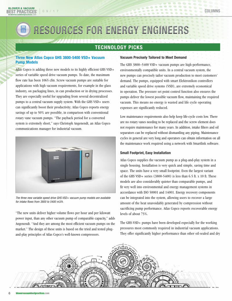
Three New Atlas Copco GHS 3800-5400 VSD+ Vacuum Pump Models
Atlas Copco is adding three new models to its highly efficient GHS VSD+
series of variable speed drive vacuum pumps. To date, the maximum
flow rate has been 1065 cfm. Screw vacuum pumps are suitable for
applications with high vacuum requirements, for example in the glass
industry, on packaging lines, in can production or in drying processes.
They are especially useful for upgrading from several decentralized
pumps to a central vacuum supply system. With the GHS VSD+ users
can significantly boost their productivity; Atlas Copco reports energy
savings of up to 50% are possible, in comparison with conventional
rotary vane vacuum pumps. “The payback period for a converted
system is extremely short,” says Christoph Angenendt, an Atlas Copco
communications manager for industrial vacuum.
“The new units deliver higher volume flows per hour and per kilowatt
power input, than any other vacuum pump of comparable capacity,” adds
Angenendt. “And they are among the most efficient vacuum pumps on the
market.” The design of these units is based on the tried and tested plug-
and-play principles of Atlas Copco’s well-known compressors.
Vacuum Precisely Tailored to Meet Demand
The GHS 3800–5400 VSD+ vacuum pumps are high-performance,
environmentally compatible units. In a central vacuum system, the
new pumps can precisely tailor vacuum production to meet customers’
demand. The pumps, equipped with smart Elektronikon controllers
and variable speed drive systems (VSD), are extremely economical
in operation. The pressure set point control function also ensures the
pumps deliver the lowest possible vacuum flow, maintaining the required
vacuum. This means no energy is wasted and life cycle operating
expenses are significantly reduced.
Low maintenance requirements also help keep life-cycle costs low. There
are no rotary vanes needing to be replaced and the screw element does
not require maintenance for many years. In addition, intake filters and oil
separators can be replaced without dismantling any piping. Maintenance
cycles in general are very long and operators can obtain information on all
the maintenance work required using a network with Smartlink software.
Small Footprint, Easy Installation
Atlas Copco supplies the vacuum pump as a plug-and-play system in a
single housing. Installation is very quick and simple, saving time and
space. The units have a very small footprint. Even the largest variant
of the GHS VSD+ series (3800-5400) is less than 6.5 ft. x 10 ft. These
models are also considerably quieter than comparable pumps, and
fit very well into environmental and energy management systems in
accordance with ISO 50001 and 14001. Energy recovery components
can be integrated into the system, allowing users to recover a large
amount of the heat unavoidably generated by compression without
sacrificing pump performance. Atlas Copco reports recoverable energy
levels of about 75%.
The GHS-VSD+ pumps have been developed especially for the working
pressures most commonly required in industrial vacuum applications.
They offer significantly higher performance than other oil-sealed and dry
The three new variable speed drive GHS VSD+ vacuum pump models are available for intake flows from 3800 to 5400 m3/h.
| 0 9 / 1 7
6 blowervacuumbestpractices.com
COLUMNS

TECHNOLOGY PICKS
vane vacuum pumps. Energy recovery keeps heat release in the vicinity
of the units to a minimum, meaning air conditioning systems are not
needed for nearby work stations.
Electronically Monitored Cooling System
The cooling system is equipped with an electronic thermostatic valve
accurately controlling the oil temperature. This means the oil retains
its optimum consistency, as any entrainment of water to the oil cycle by
condensation is avoided. The cooling system also operates with a speed-
controlled fan to minimize energy requirements. The vacuum pumps in
the GHS 3800–5400 VSD+ series are available with water or air cooling.
Due to the extremely high oil retention capacity of the GHS VSD+,
environmental impact at all operating pressures is significantly lower
than with other vacuum pumps. The range, recently extended upwards,
now includes for the first time a new, patented oil separator limiting the
residual oil level to a maximum of 3 ppm. “This means that the exhaust
air is significantly more environmentally compatible than with other oil-
injected pumps of this size available on the market,” Angenendt reports.
In addition, the Atlas Copco technology allows shorter cycle times
because the pump reacts very quickly to changed process conditions
in the pressure range relevant for the user.
The screw element has a sturdy design and a considerably longer service
life than the elements typically used in screw compressors or rotary vane
pumps. The special inlet control valve, operating in close liaison with
the variable speed drive, allows energy consumption to be minimized.
All the pumps are equipped with Elektronikon controllers and the
Smartlink remote monitoring system. The tried and tested Elektronikon
controller is easy to understand and also ensures energy savings. It can
be integrated into a process control system and can also control other
manufacturer’s vacuum pumps.
Atlas Copco is a world-leading provider of sustainable productivity
solutions. The Group serves customers with innovative compressors,
vacuum solutions and air treatment systems, construction and mining
equipment, power tools and assembly systems. Atlas Copco develops
products and services focused on productivity, energy efficiency, safety
and ergonomics. The company was founded in 1873, is based in
Stockholm, Sweden and has a global reach spanning more than 180
countries. In 2016, Atlas Copco had revenues of BSEK 101 (BEUR 11)
and about 45,000 employees. For more information, please visit http://
www.atlascopco.com/us/.
0 9 / 1 7 |
7 blowervacuumbestpractices.com
COLUMNS

RESOURCES FOR ENERGY ENGINEERS
TECHNOLOGY PICKS
Atlas Copco’s Vacuum Technique business area provides vacuum
products, exhaust management systems, valves and related products
mainly under the Edwards, Leybold and Atlas Copco brands. The main
markets served are semiconductor as well as a variety of industrial
segments. The business area has a global service network and innovates
for sustainable productivity in order to further improve its customers’
productivity. Principal product development and manufacturing units are
located in the United Kingdom, Czech Republic, Germany, South Korea,
China and Japan.
Industrial Vacuum is a division within Atlas Copco's Vacuum Technique
business area. It develops, manufactures and sells sophisticated vacuum
products and solutions for customers in the industrial process and rough
vacuum sectors, for example steel, CPI (chemical process industries),
metallurgy, petrochemical, food packaging and paper handling. The
division markets products under the Atlas Copco, Edwards, Quincy and
Leybold brands. The division's focus is to improve customers' productivity.
The divisional headquarter is in Cologne Germany, the main production
locations are in Cologne, Qingdao and Tianjin China, Lutin Czech, Valence
France and Antwerp Belgium.
ULVAC Introduces VS Single-Stage Rotary Vane Vacuum Pumps
ULVAC Technologies, Inc. has introduced the VS Series of single-stage
rotary vane pumps for a wide range of industrial vacuum applications.
The ULVAC VS650A and VS750A are robust, install-anywhere pumps,
with speeds up to 750 m3/h. These small footprint, all-in-one pumping
powerhouses are built for high reliability and ease-of-maintenance.
The VS Series models are available with air or water-cooling, offer low
vibration and are affordably priced. Featuring a built-in oil-cooling fan,
and simple to clean oil-mist trap, these compact units take up far less
space than conventional single-stage rotary vane pumps. To increase
pumping speeds even further, a mechanical booster pump can be added
for speeds up to 3,100 m3/h. Typical applications include: evaporation,
sputtering, ion plating, vacuum drying, gas exchange and leak testing.
About ULVAC Technologies, Inc.
ULVAC Technologies, Inc. is a leading supplier of production
systems, instrumentation, vacuum pumps and components for the
semiconductor, MEMS, solar, flat panel display, research automotive,
medical, electrical, and refrigeration industries. ULVAC Technologies
uses a class-10 process development laboratory and customer
demonstration facility to meet the unique needs of their different
markets. ULVAC Technologies is a subsidiary of ULVAC, Inc., made
up of 39 companies engaged in most sectors of the vacuum industry.
For more information, visit www.ulvac.com
Kice Industries Announces Release of New VJX Airlock
Kice Industries announced it has introduced the new Kice VJX Airlock to
its Rotary Airlock line. The VJX Airlock offers better performance and
reliability than other airlock valves on the market today.
“The patented bearing and seal cartridge allow us to eliminate the
need for packing material around the shaft where it passes through
the endplate,” said Tim Kice, Kice Industries. “The bearing and seal
cartridge not only outperform traditional packing material, it also
eliminates several parts previously required. This reduction in parts
reduces disassembly time greatly which will lead to more uptime, and
reduced operating cost.”
The VJX airlock is interchangeable with existing Kice Airlock models
and is designed to comply with NFPA 69 requirements.
About Kice Airlocks
Kice rotary airlocks start with heavy-duty castings that are produced
at Kice’s own foundry. State-of-the-art equipment turns Kice’s castings
into precisely machined valves with consistently tight clearances.
Kice airlocks are used in pneumatic conveying, dust control and flow
control applications
The ULVAC VS650A and VS750A are “install-anywhere” pumps with speeds up to 750 m3/h.
| 0 9 / 1 7
8 blowervacuumbestpractices.com
COLUMNS

TECHNOLOGY PICKS
About Kice Industries
Founded in 1946, Kice Industries is a fourth generation, family-owned
business based in Wichita, Kan. with a team of approximately 300
employees. Kice Industries designs complete industrial air systems and
builds most of the equipment specified for these systems. Applications
include pneumatic conveying, dust control and aspiration. A multi-
industry company, Kice Industries serves the grain, plastics, food, feed,
wood and minerals industries. Just north of Wichita, the manufacturing
and office facility totals 200,000 square feet on 25 acres. CFM
Corporation a subsidiary of Kice Industries is a gray and ductile iron
foundry located in Blackwell, OK. The foundry and machine shop is
65,000 square feet on 20 acres. For more information, please visit
www.kice.com.
New Optimized Maxum Maxumizer® Part Drying Technology
Maxum, LLC has introduced a line of Maxumizer® blowers, nozzles,
and air knives. The internal air flow design of all Maxumizer® Air
Blower systems is specifically optimized to provide higher output with
less energy in the best performance range for surface blow-off and
drying applications. In most cases this design will use 30-50 percent
less horsepower while running at much slower speeds.
The new Kice VJX Airlock
1-800-USA-PUMP I www.buschusa.com
Centralized Vacuum Systems Meeting All Application and Sizing Requirements
Efficient · Economical · Eco-Friendly
0 9 / 1 7 |
9 blowervacuumbestpractices.com
COLUMNS

Maxum’s unique approach to air blow-off
is illustrated in its innovative drive system.
The Maxum Bearing Bridge™ drive system
permits industrial parts drying and air blow-off
systems to use less energy and effectively run
on less horsepower at slower speeds, while
lasting longer. This science-based drive system
replaces the typical belt-driven system, and
employs two separate bearing cases located
on either side of the drive pulley. The unique
design provides a properly distributed bearing
load and dramatically reduces heat while
greatly improving service life. Why? “Because
this design provides properly positioned
bearing load to reduce heat and dramatically
extend service life,” says Jim Freers, President
and CEO. “In fact, this design provides 10-15
times the ‘L10’ bearing life of older cantilever
drives that rapidly fail from the uneven
overhung belt load.”
Every Maxum Air Device includes standard
output flow and pressure data, and every Maxum
RESOURCES FOR ENERGY ENGINEERS
TECHNOLOGY PICKS
FREE SUBSCRIPTIOND I G I T A L E D I T I O N F R E E W O R L D W I D E PRINT EDITION FREE TO U.S. SUBSCRIBERS
You’ll get FOUR ISSUES of each supplement this year!
Subscribe at coolingbestpractices.com or blowervacuumbestpractices.com
p Cooling Towers
p Central Plant Chillers
p Cooling System Components
EVERY ISSUE CONTAINS BEST PRACTICES FOR:
p Industrial Vacuum
p Vacuum Generation
p Industrial & Aeration Blowers
p Blow-Off Air
EVERY ISSUE CONTAINS BEST PRACTICES FOR:
Subscribe Now!
Subscribe Now!
Maxumizer® Air Blower systems provide higher output with less energy.
| 0 9 / 1 7
10 blowervacuumbestpractices.com
COLUMNS

Blower provides CFM, pressure and horsepower
required. As a result, users don’t have to guess
or “call the factory” to correctly select Maxum
products. Maxum has also developed blower
enclosures reducing the operating sound level
below 75dB at a three-foot distance. These
corrosion resistant polymer enclosures have
a small footprint, standard gauges to monitor
performance, oversize filters with pre-filters
and an integrated skid mount.
Another prime example of Maxum’s science-
based approach is its new converging and
laminar flow technology. With traditional
blow-off devices, the focused air starts
to expand as soon as it leaves the nozzle.
With Maxum’s converging and laminar flow
technology, the air reaches the part in a
stronger, faster, more concentrated form,
improving efficiency while saving energy. All
Maxumizer® Air Knives, Air Nozzles, & the
Patented Nozzle Bar® System employ this
converging and laminar flow technology.
Maxum’s innovative air blow-off and drying
equipment remove water, liquids, and
debris, successfully preparing products for
assembly, packaging, labelling, inkjet printing,
inspection, powder coating, and more, using
energy efficient blow-off equipment. Whether
it is fruit, vegetables, bottles, cans, metal
parts, circuit boards, extrusions, or any
other air blow-off application, the Maxum
mix of creativity and science ensures the
success of your application.
For more information please visit
www.maxumair.com.
Silvent Introduces New SILVENT MJ4-QS Air Nozzle Design
Silvent is introducing a new energy-efficient air
nozzle designed for quick and easy installation.
A growing number of companies are interested
in compressed air optimization, and the new
SILVENT MJ4-QS now makes it easy to equip
small, open pipes.
SILVENT MJ4-QS is a micro nozzle made of
316 L stainless steel. The nozzle is designed
with a central hole in combination with
surrounding vents. SILVENT MJ4-QS is
equipped with an adapter, easily installable
on an existing open pipe. The adapter makes
installation easy, smooth and quick, with
no impact on the equipment. The small
mounting dimensions for the nozzle can fit
on most machine designs. SILVENT MJ4–QS
is made for fixed-installations and fits 4 mm
OD open pipes.
About Silvent
Silvent helps manufacturers with energy
optimization and improved working
environment. The headquarters are located in
Borås, where all research and development
takes place. The company has unique
expertise in the area of compressed air
dynamics. Silvent’s products and customized
solutions for blowing with compressed air are
used by leading manufacturers and brands
worldwide. Today, Silvent’s products are
available in 77 countries, and in 2016 the
company’s sales brought in SEK 125 million.
Silvent is part of the Lifco Group, listed on
Nasdaq Stockholm. For more information,
please visit www.silvent.com
ZG Series Tri-lobed Blowers
Bulkmaster 6800 Series Truck Blowers
ZZ Series Drop-in Replacement Blowers
Bi-lobed MB Series Blower Packages
High Quality Blowers at an Excellent Value Eurus Blower is a $100 million corporation with 50 years of experience building high quality positive displacement blowers.
Don’t be fooled into paying more. Receive the same quality and performance while profiting from significant savings.
For more information contact Eurus Blower, PO Box 4588, Wheaton, Illinois 60189 tel: 630-221-8282 / email: [email protected] / www.eurusblower.com
Flows from 30 to 5000 cfm. / Pressures to 15 psi. / Vacuums to 15” Hg.
TECHNOLOGY PICKS
0 9 / 1 7 |
11 blowervacuumbestpractices.com
COLUMNS
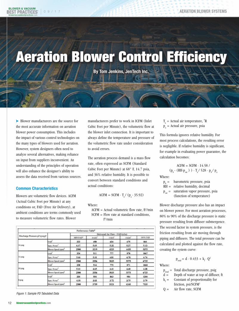
Aeration Blower Control EfficiencyBy Tom Jenkins, JenTech Inc.
c Blower manufacturers are the source for
the most accurate information on aeration
blower power consumption. This includes
the impact of various control technologies on
the many types of blowers used for aeration.
However, system designers often need to
analyze several alternatives, making reliance
on input from suppliers inconvenient. An
understanding of the principles of operation
will also enhance the designer’s ability to
assess the data received from various sources.
Common Characteristics
Blowers are volumetric flow devices. ACFM
(Actual Cubic Feet per Minute) at any
conditions or, FAD (Free Air Delivery), at
ambient conditions are terms commonly used
to measure volumetric flow rates. Blower
manufacturers prefer to work in ICFM (Inlet
Cubic Feet per Minute), the volumetric flow at
the blower inlet connection. It is important to
always define the temperature and pressure of
the volumetric flow rate under consideration
to avoid errors.
The aeration process demand is a mass flow
rate, often expressed as SCFM (Standard
Cubic Feet per Minute) at 68° F, 14.7 psia,
and 36% relative humidity. It is possible to
convert between standard conditions and
actual conditions:
ACFM = SCFM ∙ Ta / (p
a ∙ 35.92)
Where:ACFM = Actual volumetric flow rate, ft3/minSCFM = Flow rate at standard conditions,
ft3/min
Ta = Actual air temperature, ˚R
pa = Actual air pressure, psia
This formula ignores relative humidity. For
most process calculations, the resulting error
is negligible. If relative humidity is significant,
for example in evaluating power guarantee, the
calculation becomes:
ACFM = SCFM ∙ 14.58 / (p
b - (RH∙p
sat ) ) ∙ T
a / 528 ∙ p
b / p
a
Where:p
b = barometric pressure, psia
RH = relative humidity, decimalp
sat = saturation vapor pressure, psia
(function of temperature)
Blower discharge pressure also has an impact
on blower power. For most aeration processes,
80% to 90% of the discharge pressure is static
pressure resulting from diffuser submergence.
The second factor in system pressure, is the
friction resulting from air moving through
piping and diffusers. The total pressure can be
calculated and plotted against the flow rate,
creating the system curve:
ptotal
= d ∙ 0.433 + kf ∙ Q2
Where:p
total = Total discharge pressure, psig
d = Depth of water at top of diffuser, ftk
f = Constant of proportionality for
friction, psi/SCFM2
Q = Air flow rate, SCFMFigure 1: Sample PD Tabulated Data
| 0 9 / 1 7
12 blowervacuumbestpractices.com
AERATION BLOWER SYSTEMS

If an operating point of flow and pressure is known, either from
calculation or measurement, the constant kf can be calculated:
kf = (p
actual - d ∙ 0.433) / Q
actual2
Where:P
actual = Discharge pressure, psig Q
actual = Air flow rate, SCFM
The system curve is necessary to evaluate blower performance. The
intersection of the system curve with the blower performance curve
identifies the operating flow rate, pressure, and power requirement.
Regardless of the evaluation method used, it is important to identify
the conditions of the air at the blower system inlet and discharge.
The necessary parameters include:
p barometric pressure
p inlet pressure (barometric minus losses)
p inlet temperature
p relative humidity
p flow rate (SCFM preferred)
p discharge pressure
Wire-to-Air Evaluations
For any blower, the power can be calculated using:
Pwa
= ( Qs ∙ T
i ) / (η
wa ∙ 3131.6 ) ∙ X
X = ( pd / p
i )(( k - 1 ) / k ) -1
( k - 1 ) / k ≈ 0.283
Where:P
wa = wire-to-air power, kW
Qs = flow rate, SCFM
Ti = inlet air temperature, ˚Rη
wa = wire-to-air efficiency,
decimal (includes blower, motor, and VFD)
X = adiabatic factor, dimensionless
pd, p
i = discharge and inlet
pressure, psiak = ratio of heat capacity =
Cp/Cv, dimensionless
In many evaluations, the cost of electricity is taken as a composite
(average) rate. This is obtained by dividing the total cost for a month
by the total power used in a month. The annual cost determination
is straightforward:
Annual Cost = $ ⁄ kWh ∙ kWave
∙ 8760
The composite rate may not accurately reflect actual operating cost,
typically composed of several components:
p On-Peak rate, typically 12 hours per weekday
p Off-Peak rate 12 hours per weekday and 24 hours for weekends (lower than on-peak)
p Peak demand charge for highest 15-minute average per month
Join Keynote Speaker, Tom Jenkins, President
of JenTech Inc., to learn how Most-Open-Valve
control is integrated with blower control to
optimize aeration system energy requirements.
Most-Open-Valve (MOV) control is a common
modification of automatic DO control
systems. By reducing the required blower
discharge pressure, MOV can minimize power
requirements if the MOV and blower controls
are properly coordinated. This webinar will
explain the basic principles of MOV control.
Several techniques used to integrate aeration,
MOV, and blower controls to optimize system
performance and energy consumption will
be explained.
Our Sponsor Speaker is Omar Hammoud, CEO & President of APG-Neuros, whose presentation is titled, “High Speed Air Bearing Turbo Blower Control Capabilities”. This presentation will cover turbo blower performance curves and control strategies designed to optimize energy efficiency and reliability.
Receive 1.0 PDH Credit.
Register for Free Today at blowervacuumbestpractices.com/magazine/webinars
October 26, 2017 – 2:00 PM EST
Proudly Presenting the 2017 Expert Webinar Series
SPONSORED BY:
Tom Jenkins has over 30 years of experience with aeration blowers and blower controls.
Omar Hammoud is the CEO & President of APG-Neuros.
Integrating Aeration Blowers with Most-
Open-Valve
0 9 / 1 7 |
13 blowervacuumbestpractices.com
AERATION BLOWER SYSTEMS

Each of these usually represents 1/3 of total power cost. The air-flow
rates and power cost for each component can be estimated if the
average daily air flow, Qave
, is known:
QOnPeak
= QAve
∙ 1.15 QOffPeak
= QAve
∙ 0.85 QDemand
= QAve
∙ 1.20
The total annual electricity cost is the sum of On-Peak, Off-Peak, and
Demand costs.
OnPeakCost = $⁄kWhOnPeak
∙ kWOnPeak
∙ 60hr / week ∙ 52week / yearOffPeakCost = $ ⁄ kW
OffPeak ∙ kW
OffPeak ∙ 10hr / week ∙ 52week / year
DemandCost = $ ⁄ kWDemand
∙ kWDemand
∙ 12month / year
Blower performance is often referenced to efficiency, and design-point
efficiency is sometimes used to compare blowers. However, the end user
pays for energy and power, not efficiency. The total power across the
expected operating range should be used for comparisons.
Positive Displacement (PD) Blowers
Positive Displacement (PD) blowers move a fixed volume of air from
inlet to discharge for every revolution of the blower shaft. For positive
displacement blowers at a given speed, the performance “curve” is
quite linear. The total blower volumetric air-flow rate will not change
substantially with discharge pressure, but power will increase with
increasing pressure.
There are two types of PD blowers commonly used in wastewater
treatment. The lobe type PD (often referred to as a “Roots” blower) has
been available for 150 years. The newer type screw PD blowers provide
excellent efficiency and broad operating ranges, albeit at a higher capital
cost than lobe types.
Regardless of type, modulating the PD’s air flow rate requires varying the
blower speed. The most practical technique for doing this is the variable
frequency drive (VFD).
PD blower performance may be provided in various formats.
Manufacturer’s formulas and characteristics may be available, although
this information is often considered proprietary. It is more common to
provide tabulated data indicating flow and power at various speeds and
pressures. See Figure 1. Linear interpolation can be used to determine
performance at operating points not included in the table. The “forecast”
function in spreadsheet programs is a useful tool for interpolation.
Graphical representation of PD performance is also useful in estimating
performance for variable speed PD blowers. See Figure 2. It should
be noted neither flow, or pressure performance, has a zero intercept.
This is a result of the blower’s internal leakage and mechanical friction.
Using speed ratio alone will produce significant inaccuracies. The
conventional formulas for calculating lobe type PD blower performance
illustrates the non-zero intercept:
ICFM = ( Nactual
- Nslip
) ∙ CFR
bhp = [ 0.0044 ∙ Nactual
∙ CFR ∙ ∆p ] + FHP
Where:N = rotational speed, rpm (N
slip is the speed required
to offset internal leakage)CFR = blower displacement, cubic feet per revolutionbhp = blower shaft power, brake hpFHP = friction horsepower, bhp
Dynamic Blowers
Dynamic blowers, commonly called centrifugal blowers, have more
complex performance characteristics than PD blowers. Centrifugal
blowers convert the kinetic energy of the rotating impeller to kinetic
energy in the air stream. In the diffuser section, and in the volute, some
of this kinetic energy (i.e. velocity pressure) is converted to potential
energy (i.e. static pressure). Unlike PD blowers, centrifugal blower
flow-rate and discharge pressure are influenced by the density of inlet
air, and by the process system’s resistance to flow.
Figure 2: Sample PD Graphical Data
AERATION BLOWER CONTROL EFFICIENCY
| 0 9 / 1 7
14 blowervacuumbestpractices.com
AERATION BLOWER SYSTEMS
There are three types of centrifugal blowers used in wastewater
treatment.
p Multistage blowers achieve required discharge pressure by successive compression in each stage.
p Geared single stage blowers achieve required discharge pressure by high impeller rotational speed. Standard motors are connected to the blower by speed increasing gear boxes.
p High speed gearless blowers, commonly called turbo blowers, achieve required discharge pressure by high rotational speed. The impellers are mounted directly on special motors, operating at several thousand rpm, and are powered through VFDs with output frequencies of several hundred Hz.
There are a variety of techniques used to modulate the flow rate
of centrifugal blowers:
p Inlet throttling, typically with a butterfly valve, creates a pressure drop at the blower inlet. This method is inexpensive, but also has the lowest energy efficiency. Throttling can be used on any type of centrifugal blower, but it is common only on multistage blowers.
p Guide vanes, both on inlet and discharge, are generally found on geared single-stage blowers. Guide vanes modify the blower performance by changing the pressure vs. flow characteristics. Inlet guide-vanes pre-rotate the air, reducing the kinetic energy transferred. Variable discharge diffuser vanes modify the conversion of velocity pressure to static pressure. Both are more efficient than throttling, but introduce a loss in efficiency at low flows by creating a pressure drop.
p Variable speed, typically using VFDs, can be used with any centrifugal blower and is always used with turbo blowers. This is both the most efficient and most expensive control method. Varying blower-speed shifts the blower performance curve down and to the left.
Determining the performance of a centrifugal blower first requires
calculating the impact on the performance curve of differences between
the air density used to develop the manufacturer’s curves, and the actual
site density. Then, a family of curves is developed from the new curve,
identifying the performance with several levels of modulation. Finally, the
system curve is superimposed on these curves to identify the flow rate.
Howden Roots is proud to continue building the Roots legacy, begun in 1854 by the Roots brothers, by manufacturing the world-renowned rotary positive displacement blowers and centrifugal compressors in Connersville, Indiana, U.S.A.
Each Howden Roots rotary positive displacement blower, centrifugal compressor and ExVel Turbo Fan is designed and fabricated to unique applications within a wide array of industries such as: pneumatic conveying, gas separation, wastewater treatment, steam compression, and petrochemical production.
To maintain optimized production levels, Howden Roots factory maintenance and repair services are available around the world.
EASYAIR X2 Blower Package System
Univeral RAI Bi-lobe Blower
RGS-J Gas Compressor
TRI-NADO Tri-lobe Exhauster
Centrifugal Compressor
For further information contact Howden Roots • 900 West Mount Street, Connersville, IN, U.S.A.Tel: 1-800–55-ROOTS (76687) • Email: [email protected] • www.howdenroots.com
© Howden Group Ltd. All rights reserved. 2016
Howden Roots – Setting the Standard Since 1854
0 9 / 1 7 |
15 blowervacuumbestpractices.com
AERATION BLOWER SYSTEMS

To read similar articles on Aeration Blowers, please visit http://blowervacuumbestpractices.com/technology/aeration-blowers.
For inlet throttling, creating a modulated curve requires calculating
the pressure drop through the throttling valve at several flow rates.
Next, calculate the discharge pressure using the new inlet pressure
and the unthrottled pressure ratio. The pressure drop through the
valve is determined from Cv, this in turn is a function of the valve
design and position:
∆pv = ( Q
s / ( 22.66 ∙ C
v ))2 ∙ ( SG ∙ T
u ) / p
u
Where:Δp
v = pressure drop across the valve, psi
Qs = flow rate, SCFM
Cv = valve coefficient from manufacturer’s data, dimensionless
SG = specific gravity, dimensionless, (1.0 for air)T
u = upstream absolute air temperature, ˚R
pu = upstream absolute air pressure, psia
Inlet guide vane operation is more complex, and the manufacturer
usually supplies a set of curves showing performance at several vane
positions. These curves need adjustment for changes in inlet density.
The system curve can then be superimposed to determine performance.
See Figure 3.
Centrifugal blowers controlled with VFDs don’t follow simple linear
relationships like PD blowers. Regardless of the type of centrifugal, the
affinity laws must be used to create the modulated performance curves:
See Figure 4.
Qa = Q
c ∙ N
a / N
c
Xa = X
c ∙ ( N
a / N
c )2
Pa = P
c ∙ ( N
a / N
c )3
pd = p
i ∙ [ ( X
a + 1 )(k/(k-1)) ]
Where:Q
a,c = actual and curve volumetric flow rate, ICFM
Na,c
= actual and curve rotational speed, rpmX
a,c = actual and curve adiabatic factors, dimensionless
Pa,c
= actual and curve blower power, hpp
d,i = inlet and discharge pressure, psia
Conclusion
Calculations for optimizing blower efficiency for aeration systems
always involve the blower characteristics, the control system’s effect
on the blower performance, and the process system requirements.
By using the proper calculation methodology, blower-system energy
consumption for various blowers and control schemes can be
estimated. This permits the designer to evaluate the life-cycle cost for
several alternative designs. The result will be a system economically
meeting the end user’s objectives.
For more information contact Tom Jenkins, President, JenTech Inc. at email: [email protected] or visit www.jentechinc.com. Mr. Jenkins has texts now available in hardcopy and electronic versions titled Aeration Control and Facility Design at www.riley.com and www.e-wef.org/store.
Figure 3: Example Inlet Guide Vane Control
Figure 4: Variable Speed Centrifugal
AERATION BLOWER CONTROL EFFICIENCY
| 0 9 / 1 7
16 blowervacuumbestpractices.com
AERATION BLOWER SYSTEMS

Danish Furniture Producer Kvist Switches Plants to
CENTRALIZED VACUUM SYSTEMSBy Uli Merkle, Head of Marketing Services, Busch Vacuum Pumps and Systems
c High-quality seating furniture is the main
product of Kvist Industries A/S. The Danish
designer’s furniture's wooden components
are made from solid wood or molded
wood. To meet their own high-quality
requirements, and the exclusive demands of
customers, manual processing performed by
experienced personnel plays an important
role. In particular, great attention is paid to
the perfect finish of the surfaces, requiring
expert craftsmanship. Automatic fabrication
of the parts is performed on six different CNC
processing machines. The individual parts are
clamped with a vacuum generated by Mink
claw vacuum pumps from Busch.
Founded 50 years ago, Kvist is a family
business now being run by its third
generation. Initially, Kvist dealt with
manufacturing molded wood parts, mainly
produced for various manufacturers of
seating furniture. Today, their focus is on
completely manufacturing their own seating
furniture and tables, sold worldwide to end
users via other furniture manufacturers.
Kvist's main markets are Germany and
Scandinavia, but the significance of the
Chinese market is growing as Chinese
customers are increasingly interested in
Kvist products. After 50 years, chairs and
armchairs with designs from their initial years
have become classics, now experiencing a
renaissance in the product range. However,
newly designed seating furniture is also part
of Kvist's portfolio (Figure 1). Kvist Industries
A/S’s headquarters is located in the Danish
town of Arre with two production plants. One
of the plants produces seating furniture, while
the other manufactures tables.
Kvist operates an additional production facility
in Latvia, where 650 employees manufacture
individual parts. Final assembly and quality
assurance of this seating furniture is then
mainly performed at the headquarters in Arre.
Figure 1. High quality chairs and armchairs in all forms and versions are the main products of Kvist Industries A/S in Denmark.
0 9 / 1 7 |
17 blowervacuumbestpractices.com
INDUSTRIAL VACUUM & BLOWER SYSTEMS

DANISH FURNITURE PRODUCER KVIST SWITCHES PLANTS TO CENTRALIZED VACUUM SYSTEMS
Centralized Vacuum Systems Using Three Mink Claw Vacuum Pumps
A centralized vacuum system with three Mink
claw vacuum pumps is used in each of the two
Danish plants to generate the vacuum required
for clamping. Both central vacuum system units
have been in operation since July 2015 when
they replaced the previously used dry-running
rotary vane and liquid ring vacuum pumps.
The rotary vane vacuum pumps required a
lot of maintenance due to wear on the vanes.
In addition, this vacuum generator gave off
waste-heat directly into the production room.
Its loud operating noise was also extremely
uncomfortable for the employees. The water
level of the liquid ring vacuum pumps had
to be monitored constantly, and refilled or
exchanged if the water became polluted with
wood dust.
Technical Director, Rune Kvist, was not
satisfied with either type of vacuum generator,
since the performance was not consistent. This
sometimes lead to clamping problems because
the vacuum did not achieve the required level
or achieved it too slowly. Rune Kvist found the
optimum vacuum supply with the two central
vacuum system units from Busch: "We used
to have a total of six vacuum pumps installed
at three CNC processing centers with two
processing tables for our seated furniture
production. The associated waste heat and
noise problems had a negative effect on the
work stations. Today, we have three Mink claw
vacuum pumps outside the building that go
unnoticed except for the fact that we always
have the vacuum we require for clamping,"
said Rune Kvist.
In addition, operational reliability was
significantly increased. The required vacuum
is immediately available at any time because
the pipework between the vacuum pumps and
the CNC machines serves as a vacuum buffer,
where a constant vacuum of 200 millibars
is maintained (Figure 2). The high level of
operational reliability is also guaranteed by
the demand-based control system. The only
vacuum pumps in operation are the ones
actually needed to maintain the vacuum
level in the pipework system. In practice, a
maximum of two of the three installed Mink
vacuum pumps accomplish this. So, if one of
Figure 2. Solid wood and molded wood components are processed on several CNC machines.
| 0 9 / 1 7
18 blowervacuumbestpractices.com
INDUSTRIAL VACUUM & BLOWER SYSTEMS

DANISH FURNITURE PRODUCER KVIST SWITCHES PLANTS TO CENTRALIZED VACUUM SYSTEMS
them were to fail, this would have no effect
on production.
In Addition to Enhanced Safety and Reliability – Significant Energy Savings
An additional essential benefit of the
centralized vacuum system, huge energy
savings, is made possible by the Mink claw
vacuum pumps' demand-based control system
and frequency-controlled drive (Figure 3).
Firstly, a Mink claw vacuum pump requires less
energy than comparable vacuum pumps of a
similar size. This is made possible by contact-
free and wear-free claw vacuum technology.
Furthermore, the pumping speed and vacuum
performance remain constant throughout the
entire life-cycle. Whereas the pumping speed
and achievable vacuum level of dry-running
rotary vane vacuum pumps declines due to
wear on the vanes. This is why one smaller
Mink claw vacuum pump can often replace a
larger dry-running rotary vane vacuum pump.
In practice, this means less motor output is
required for comparable pumping speed.
As a basic principle, fewer vacuum pumps are
needed for centralization of a vacuum supply
than for decentralized installation directly at
the CNC processing centers. This is how the
previously installed six rotary vane vacuum
pumps were replaced by three new Mink
vacuum pumps. Six rotary vane vacuum pumps
used to operate during all working hours. In
practice, the centralized vacuum system unit
has demonstrated only one Mink vacuum pump
operates at 50 hertz during working hours and
a second is sometimes automatically turned
on, but only briefly and usually at a lower
frequency. This gives Kvist energy savings of
61% or 22,600 kilowatt hours per year for
seated furniture production alone (Figure 4).
The second centralized vacuum system, used for
manufacturing tables, achieves similar values.
Rune Kvist is satisfied with the centralization
of the vacuum supply. This is why he has also
decided to use this technology at the new
plant in Latvia, and has installed two identical
centralized vacuum systems with Mink claw
vacuum pumps.
According to Rune Kvist, "maintenance of
the Mink claw vacuum pumps amounts to
practically nothing." They have a maintenance
contract with Busch, including annual
inspection of all Mink claw vacuum pumps
and the changing of the gear oil. Due to wear-
free operation of the claw vacuum technology,
there is no need to exchange wear parts like
the vanes of rotary vane vacuum pumps, nor
for tasks related to operating fluids for liquid
ring vacuum pumps.
About Busch
Busch Vacuum Pumps and Systems is
a leading manufacturer and retailer of
vacuum pumps, blowers, compressors and
customized systems using vacuum technology.
With over 50 years of experience and the
largest selection of industrial vacuum pumps
available today, Busch meets the demand for
vacuum and pressure technologies in every
industry across the world.
For more information, visit www.buschusa.com
To read similar articles on Woodworking Industries, please visit http://blowervacuumbestpractices.com/
industries/woodworking
Figure 3. Mink claw vacuum pumps generate the vacuum for clamping on the CNC processing machines in centralized vacuum systems at two Kvist plants in Denmark.
Figure 4.
0 9 / 1 7 |
19 blowervacuumbestpractices.com
INDUSTRIAL VACUUM & BLOWER SYSTEMS

Custom Blower and Air Knife Bin Drying Solution REDUCES PACKAGER LABOR HOURSBy Kacie Goff, JetAir Technologies
c Putting wet product into secondary packaging can cause any
number of issues. Damp cardboard deteriorates, rewetted labels go
askew, water spots compromise consumer confidence. What happens
though, when the secondary packaging itself is wet? This was the
question Scholle IPN, a leader in bag-in-box and spouted pouch
packaging, turned to JetAir Technologies and Valley Packline Solutions
to answer.
Scholle provides boxed wine bladders. In order to conveniently ship
these bladders to their customer, they designed reusable, collapsible
bins. The customer could empty out the bin, then return it to Scholle
to be refilled with a fresh batch of wine bladders.
Once the bins returned to Scholle, they were cleaned before refilling.
Three Scholle employees re-erected and pressure washed these bins
at a pace of 60 bins per hour.
The Problem
Although the collapsible bins were convenient for the customer,
Scholle was dedicating 120 hours each week to prepare them for
reuse. In order to streamline their process, they got in touch with
the line engineers at Valley Packline Solutions. Valley Packline is the
expert in designing, engineering, and manufacturing produce handling
and processing equipment. They quickly found a way to optimize
the bin cleaning by introducing a system pulling bins directly off the
truck. This system then fed the bins straight into an erector/washer,
eliminating the pressure washer.
After going through the erector/washer, the bins were then fed into the
facility to be refilled with wine bladders. In short, Valley Packline had
automated a system taking bins from the truck, and delivering them
clean to Scholle.
Drying Station 1 at Scholle IPN.
| 0 9 / 1 7
20 blowervacuumbestpractices.com
INDUSTRIAL VACUUM & BLOWER SYSTEMS

The re-erecting and cleaning process could now connect directly
with the refilling process. While great for optimizing facility flow, this
did present a problem. Any time between the cleaning and refilling,
previously allowing the bins to dry, was gone.
The bins couldn’t be refilled while wet, and common air knives couldn’t
reach the bins’ deep corners to thoroughly dry them by the time they
were fed into the facility.
To the Testing Facility
As experts in drying, JetAir Technologies was there to help. JetAir knew
this was a unique application, especially because of the large size of the
bins, so they headed to their testing facility to try an array of solutions
to find the ideal setup for Scholle. Using a sample bin at their testing
facility, JetAir modeled a number of configurations of blowers and air
knives to ensure the best results.
JetAir has a wide range of blower-based solutions. They routinely test
centrifugal and regenerative blowers to find the best balance of flow and
pressure for the specific application. Leveraging their in-house testing
facility, they are able to replicate plant conditions.
Thorough testing of this unique bin-drying application allowed JetAir
to arrive at its blower and custom air knife recommendation. “It was
quite an extensive project to put in a drying system,” said Adam Fehr,
Valley Packline’s sales manager. “Testing was very helpful in making
a decision.”
An Energy Saving Blower
By testing multiple air pressures and flows, JetAir arrived at a way
to contribute to ongoing energy savings. Many air knife systems rely
on compressed air as their air source. This creates a handful of
challenges. First, compressors do not deliver a clean air stream (i.e.
there is oil from the compressor in the air stream). Food-grade oil
can be purchased to use with the compressor, but it is more expensive
than standard compressor oil. This means an ongoing additional
expenditure, leading to an additional issue with using compressed air,
the cost of the air itself.
Compressors produce more pressure than needed for most applications,
including the drying of these collapsible bins. Using compressed air
would have led to large amounts of air simply being blown to the
atmosphere. Not only does this mean wasted resources, it means wasted
money. In short, compressed air is expensive.
Instead of relying on compressed air, Valley Packline and JetAir turned
to a solution resulting in significantly less energy expenditure. They
drove the drying system with a centrifugal blower connected to a variable
frequency drive.
The centrifugal blower gives greater control of flow and pressure than
an air compressor. The increased control results in a staggering 70%
reduction in energy consumption over a compressed air system. By
choosing a blower over compressed air, Valley Packline and JetAir
Technologies built energy efficiency into the bin dryer.
The bin system designed by Valley Packline Solutions.
0 9 / 1 7 |
21 blowervacuumbestpractices.com
INDUSTRIAL VACUUM & BLOWER SYSTEMS

Belt-Free Blower Benefits
What’s more, JetAir’s centrifugal blowers differ from most others on the
market because they are belt-free. While most centrifugal blowers rely
on belts and tensioners, JetAir’s blowers couple the impeller directly
to the motor shaft. This means an 8% improvement in efficiency over
belted blowers, plus the elimination of the hassle of changing and
re-tensioning belts. A belt-free blower has no belt to break, so Scholle
gained minimized maintenance concerns and no belt pinch safety
hazards. Additionally, because the impeller and motor shaft are directly
connected, this blower’s footprint was less than half of a belted blower’s.
To get even more efficiency from the blower, JetAir leveraged a variable
frequency drive (VFD). With the VFD, facilities can connect directly
to their PLC. This allows them to get non-spiking soft-starts, more
precision in their airflow settings, and built-in motor protection.
Custom Air Knives
After testing, JetAir also discovered standard air knives would not be
sufficient for the application. Instead, they designed, engineered, and
manufactured custom square rings of JetBlasts (nozzled air knives)
capable of moving up and down the bin interior and exterior for rapid
and thorough drying.
JetAir chose nozzled air knives over traditional air knives for greater
efficiency. By forcing air through engineered nozzles, these JetBlasts
deliver superior air reach. The aerodynamic design of the JetBlast
balances pressure evenly across all nozzles, projecting a clean, high-
velocity air stream.
Valley Packline actuated the air knives to bathe the bins in high-flow,
high-efficiency, blower-powered air. While one square ring of JetBlast air
knives ran up and down the bin’s exterior, another simultaneously ran
up and down the interior.
After drying the interior and exterior walls, the bin moved to a secondary
drying station. At this dryer, additional sets of JetBlast air knives removed
water along the bin’s base, drying both the interior and exterior bottom.
Saving Time, Saving Energy
At Scholle IPN, Valley Packline’s engineering experience and JetAir’s
drying expertise came together to deliver an automated, energy efficient
solution. Ultimately, the new system eliminated 120 man-hours each
week dedicated entirely to erecting and washing. The new system can be
manned by just one employee as it pulls bins directly off delivery trucks,
re-erects, washes, and dries them, and feeds them into the facility for
refilling. Throughput at Scholle was improved by the system, while
energy costs were kept to a minimum.
On working with JetAir, Fehr said, “You guys did great. The timely testing
helped us show that it worked. The equipment came out very nice.”
To see a video of the installed bin washer and dryer including the
actuated air knives, see the Youtube video Valley Packline Solutions Bin
Washing and Drying.
JetAir is dedicated to delivering the most energy-efficient drying solution.
Replacing compressed air can help slash energy consumption, but
determining the right blower can pose a challenge for line engineers
and plant managers. For unique applications, testing can be leveraged
to determine optimal pressure and flow.
Finding the right blower-based solution is key for facilities wanting to save
time, energy, and ultimately money. Once identified, the right air source
will deliver the right flow and pressure along with savings in perpetuity.
For more information, contact Kacie Goff at JetAir Technologies via phone: (805) 654-7000, via email: [email protected], or visit www.jetairtech.com.
CUSTOM BLOWER AND AIR KNIFE BIN DRYING SOLUTION REDUCES PACKAGER LABOR HOURS
To read more articles on Drying and Blow-Off Applications, please visit http://blowervacuumbestpractices.com/technology/air-knives-nozzles.
JetAir’s Belt Free Blower Technology.
JetAir’s JetBlast Nozzled Air Knife.
| 0 9 / 1 7
22 blowervacuumbestpractices.com
INDUSTRIAL VACUUM & BLOWER SYSTEMS

CUSTOM BLOWER AND AIR KNIFE BIN DRYING SOLUTION REDUCES PACKAGER LABOR HOURS
WEFTEC is the one event for professionals, industry experts, and the most innovative companies from around the world. Learn from the very best thought-leaders in water quality.
Attending WEFTEC connects you to the pulse of the water quality sector and provides the tools, knowledge, and
know-how for professional success.
REGISTER NOW
www.weftec.org
MCCORMICK PLACE CHICAGO CONFERENCE SEP 30 – OCT 4, 2017EXHIBITION OCT 2 – 4, 2017

Beware Dense Phase Pneumatic Conveying RUNNING AS A DILUTE PHASE SYSTEM
By Hank van Ormer, Van Ormer Consulting
c When a dense phase pneumatic material
conveying system can’t meet the required
increase in production without adding an
additional system, often the production is
increased by just pushing more compressed
air into the transfer pipe. But, at some point,
the critical particle velocities get so high that
the system is now close to a dilute phase. This
action is not uncommon and causes many
maintenance quality and production issues,
and wasted energy.
This article reviews two common pneumatic
conveying system types and the importance for
each operating plant to know their design and
operating parameters particularly conveying air
flow velocity and particle velocity profile.
In many manufacturing operations, a
significant compressed air use is pneumatic
conveying of many types of materials such as
cement, fly ash, starch, sugar, salt, sand, plastic
pellets, etc. All of these conveying systems use
compressed air, or in some cases vacuum,
in some form to create pipe line conditions
which will allow the product material to flow
“With proper data, plant personnel can evaluate the economics to convert to an improved dilute phase system - or add additional dense phase systems as required to reach the production levels.”
— Hank van Ormer, Van Ormer Consulting
| 0 9 / 1 7
24 blowervacuumbestpractices.com
INDUSTRIAL VACUUM & BLOWER SYSTEMS

smoothly in the pipe line to the open end,
avoiding production and quality issues.
These conveying systems are usually engineered
by the conveyor system manufacture to meet
the plants specific production requirements,
planned transfer path, and most importantly,
their analysis of the specific material. Once
installed, tested, and operational, the system
should run as designed unless changes are
made such as, air flow; pipe line pressure;
piping size and/or configuration; and “particle
material characteristics”.
Operating Energy Cost
The primary operating energy cost is the
source of the compressed air, or vacuum,
used to create and maintain the conveying
air flow during the transfer time. The higher
the required inlet pressure (psig) and inlet
air volume (scfm), the higher the inlet
compressed air energy cost per scfm/yr.
Figure 1 shows how pressure ranges dictate
the appropriate compressed air source - 50
to 100 psig air compressors or 6 to 15 psig
blower air for optimum efficiency (blowers
can go as low as <3 psig).
Low Pressure Systems: Dilute Phase Systems under 15 psig
The two most distinct categories of compressed
air driven pneumatic conveying are low
pressure and high pressure systems.
Low pressure systems, also referred to as
dilute phase pneumatic conveying systems,
utilize entry air pressure under 15 psig to
flow materials through the conveying line at
relatively high velocities suspended in the air
stream. They are described as low pressure/
high velocity systems and have a high air-to-material ratio.
A typical dilute phase, low pressure system will
use a pick-up conveying air velocity of around
3,000 feet per minute at the beginning of the
system, and about 6,000 feet per minute at the
end. The conveying line pressure is 15 psig or
lower at the beginning and near atmospheric
pressure at the end.
p Particle velocity is very critical. Too low and the product falls from the air stream to the bottom of the pipe. Too high can cause particle-to-particle impact and particle-to-wall impact which will cause product degradation; fouling of the transport pipe walls; and plugging of the pipe. All which exacerbate any wear issues in the pipe and elbows.
p Certain material particles are more susceptible to dilute phase high velocity issues than others. These are:
` Friable Particles - subject to breakage due to impact with each other or the walls can experience product degradation. Too high velocity impact can create heat at the impact points of the pipe line wall and leave coatings of product on the pipe. This can ultimately lead to fouling.
` Abrasive Particles - high velocity may cause significant transport line and elbow wear, creating too high of downtime and maintenance issues (proper evaluation is much more complex than this).
When issues of this type are present, most
plants will consider selecting a higher pressure,
dense phase pneumatic conveying system.
Figure 2. Dilute Phase Pneumatic Material Conveying -- image courtesy of VAC-U-MAX
Based on .05/kWh, 8760 hrs per year, .93 ME
PRESSUREAPPROXIMATE HORSEPOWER
INPUT ESTIMATED ELECTRICAL COST $ SCFM/YR
100 psig 220 hp $77,295 $154.59
50 psig 133 hp $46,735 $93.47
15 psig 92 hp $32,355 $64.71
6 psig 33 hp $11,555 $23.11
Figure 1. Relative electrical energy cost to produce 1,000 scfm of compressed air various pressures
0 9 / 1 7 |
25 blowervacuumbestpractices.com
INDUSTRIAL VACUUM & BLOWER SYSTEMS
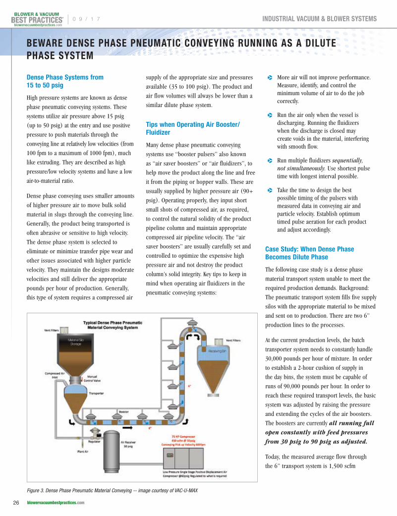
Dense Phase Systems from 15 to 50 psig
High pressure systems are known as dense
phase pneumatic conveying systems. These
systems utilize air pressure above 15 psig
(up to 50 psig) at the entry and use positive
pressure to push materials through the
conveying line at relatively low velocities (from
100 fpm to a maximum of 1000 fpm), much
like extruding. They are described as high
pressure/low velocity systems and have a low
air-to-material ratio.
Dense phase conveying uses smaller amounts
of higher pressure air to move bulk solid
material in slugs through the conveying line.
Generally, the product being transported is
often abrasive or sensitive to high velocity.
The dense phase system is selected to
eliminate or minimize transfer pipe wear and
other issues associated with higher particle
velocity. They maintain the designs moderate
velocities and still deliver the appropriate
pounds per hour of production. Generally,
this type of system requires a compressed air
supply of the appropriate size and pressures
available (35 to 100 psig). The product and
air flow volumes will always be lower than a
similar dilute phase system.
Tips when Operating Air Booster/Fluidizer
Many dense phase pneumatic conveying
systems use “booster pulsers” also known
as “air saver boosters” or “air fluidizers”, to
help move the product along the line and free
it from the piping or hopper walls. These are
usually supplied by higher pressure air (90+
psig). Operating properly, they input short
small shots of compressed air, as required,
to control the natural solidity of the product
pipeline column and maintain appropriate
compressed air pipeline velocity. The “air
saver boosters” are usually carefully set and
controlled to optimize the expensive high
pressure air and not destroy the product
column’s solid integrity. Key tips to keep in
mind when operating air fluidizers in the
pneumatic conveying systems:
p More air will not improve performance. Measure, identify, and control the minimum volume of air to do the job correctly.
p Run the air only when the vessel is discharging. Running the fluidizers when the discharge is closed may create voids in the material, interfering with smooth flow.
p Run multiple fluidizers sequentially, not simultaneously. Use shortest pulse time with longest interval possible.
p Take the time to design the best possible timing of the pulsers with measured data in conveying air and particle velocity. Establish optimum timed pulse aeration for each product and adjust accordingly.
Case Study: When Dense Phase Becomes Dilute Phase
The following case study is a dense phase
material transport system unable to meet the
required production demands. Background:
The pneumatic transport system fills five supply
silos with the appropriate material to be mixed
and sent on to production. There are two 6”
production lines to the processes.
At the current production levels, the batch
transporter system needs to constantly handle
30,000 pounds per hour of mixture. In order
to establish a 2-hour cushion of supply in
the day bins, the system must be capable of
runs of 90,000 pounds per hour. In order to
reach these required transport levels, the basic
system was adjusted by raising the pressure
and extending the cycles of the air boosters.
The boosters are currently all running full open constantly with feed pressures from 30 psig to 90 psig as adjusted.
Today, the measured average flow through
the 6” transport system is 1,500 scfm
BEWARE DENSE PHASE PNEUMATIC CONVEYING RUNNING AS A DILUTE PHASE SYSTEM
Figure 3. Dense Phase Pneumatic Material Conveying -- image courtesy of VAC-U-MAX
| 0 9 / 1 7
26 blowervacuumbestpractices.com
INDUSTRIAL VACUUM & BLOWER SYSTEMS

average (velocity up to 3,825 ft/min), and
sustained peaks of 2,600 scfm (velocity 6,640 ft/min). The outcome? This plant
unknowingly converted their dense phase
system to dilute phase. These air velocities
and probable particle velocities are high
even for a dilute phase system. The calculated
conveying air velocity is based on the entry
pressure, but with all the booster feeds and
higher volume of air the estimate of pipeline
pressure to calculate particle velocity is rough
at best.
Results After Plant Modifications
Product quality has faced issues. The scrap
rate of the product conveyed increased
about 20% over the last three years,
according to plant personnel. No specific
value was available. Pipeline repair,
maintenance and downtime have gone
from a non-issue to a constant problem.
no specific value was available.
Future Short Term Action Plan: Measure
the “actual particle velocities” of each
product at critical locations with a non-
invasive, particle velocity monitor and control
system to set up an accurate particle velocity
profile. Simultaneously at strategic locations,
measure the actual pipe line pressure and
using the measured inlet flow, calculate
the conveying air velocity. This will provide
an accurate conveying air velocity/particle
velocity profile.
Identify the operating profile of the particle
speed to find the safe zones and try to maintain
these levels. Keep production levels up along
with minimizing quality and maintenance issues.
Future Long Term Action Plan: With
proper data, plant personnel can evaluate
the economics to convert to an improved
dilute phase system - or add additional
dense phase systems as required to reach
the production levels.
At this point, the plant has the worst part of
both types – high energy cost of compressed
air for dense phase, but high volume of dilute
(scfm) phase at the same expensive air, and
high particle velocities driven issues of dilute
phase. The measurement data acquisition
plan will not only help to get to the optimum
system, but will be a key in maintaining
optimum performance on a long term basis.
For more information contact Hank van Ormer at email: [email protected].
BEWARE DENSE PHASE PNEUMATIC CONVEYING RUNNING AS A DILUTE PHASE SYSTEM
To read similar articles on Pneumatic Conveying Technology visit
http://www.blowervacuumbestpractices.com/technology/conveying
PRODUCTION RATE INCREASED DOES MEET PRODUCTION WHEN RUNNING
Original Energy Cost 1000 fpm (392 scfm @ 50 psig)392 x $64.71 scfm/yr = $25,366 per year at 8760 hrs/yr
Current Energy Cost2000 scfm average – 392= additional 1608 scfm @ 100 psig produced
= 1608 x $154.39 = $248,259/yr
Total Current Energy Cost $248,259 + $25,366 8760 hrs/yr = $273,625/yr
Values are based on 8760 hrs/yr The plant runs the system at about 45% utilization
Estimated Original Energy Cost $11,414/yr at 45% utilization
Current Energy Cost $123,131/yr at 45% utilization
Net Increase in Energy Cost $111,716/yr at 45% utilization
Figure 4. Increase on Conveying Air / Particle Velocity
FREESUBSCRIPTIONDIGITAL EDITION FREE WORLDWIDE PRINT EDITION FREE TO U.S. SUBSCRIBERS
Subscribe at blowervacuumbestpractices.com
EVERY ISSUE CONTAINS BEST PRACTICES FOR
Industrial Vacuum
Vacuum Generation
Industrial & Aeration Blowers
Blow-Off AirSubscribe Now!
0 9 / 1 7 |
27 blowervacuumbestpractices.com
INDUSTRIAL VACUUM & BLOWER SYSTEMS

Pfeiffer Vacuum Breaks Ground for New Headquarters in North America
Pfeiffer Vacuum, one of the world’s leading
providers of high-tech vacuum solutions for the
semiconductor, industrial, coating, analytical
and R&D markets, is breaking ground in
Nashua, New Hampshire, on a new, two-story,
27,000 square foot building. This modern
construction will house the North American
headquarters for administration, sales, product
management, marketing and customer care.
In parallel, the existing 24,000 square foot
building will be converted to a Service Center
of Excellence, bringing together under one
roof all service activities of the entire Pfeiffer
Vacuum product portfolio. State-of-the-art
automated cleaning and test equipment will be
utilized to produce the highest quality repairs
in a timely manner.
“These investments are further evidence of our
ongoing commitment to support our valued
customers throughout North America, while
at the same time providing a modern, best-in-
class work environment for our staff for many
years to come,” said Dr. Matthias Wiemer,
Management Board Member at Pfeiffer Vacuum
Technology AG.
About Pfeiffer Vacuum
Pfeiffer Vacuum was founded in 1890 in
Asslar, Germany. It has about 2,400 employees
worldwide and more than 20 subsidiaries. Its
service program extends from vacuum pumps
and chambers through measurement and
analysis equipment, right up to leak testing and
leak detectors and complete vacuum systems,
as well as service and technical support.
For more information, please visit
www.pfeiffer-vacuum.com.
Busch COBRA BC 0100 Achieves Milestone at Global Foundries in Germany
For twelve years of continuous operation,
amounting to over 18.9 billion rotations, a
Busch COBRA BC 0100 dry screw vacuum
pump passed this remarkable milestone in
a semiconductor foundry in Germany. Thus,
living up to its reputation for robustness,
reliability and low maintenance.
The COBRA BC 0100 in question has been in
continuous operation at the Global Foundries
production site in Dresden, Germany, since
2005 and is the longest-operating COBRA
BC 0100 at the site, known as Fab 1. Fab
1 in Dresden was the world's first fab to
manufacture microchips with copper wiring
in industrial quantities – a technology now
the basis for semiconductor production
throughout the world.
A total of two-hundred and three (203) COBRA
BC 0100 dry screw vacuum pumps are installed
at the Dresden site, producing 300 mm wafers
for the semiconductor industry. Thirty-one
(31) of these COBRA BC 0100s have been in
continuous operation for over 10 years, and
fifteen (15) of the COBRA BC 0100s have passed
the milestone of 100,000 operating hours (over
11 years of operation). Generally, continuous
operation over five or six years is the industry
expectation in load-lock applications.
COBRA BC 0100 vacuum pumps are
predominantly used in the load-lock
applications of epitaxy and physical vapor
deposition (PVD) processes. They are also
used in other contamination-free processes
for wafer handling and metrics to assure the
quality of the lithography process.
The COBRA BC 0100 is a dry screw vacuum
pump within the proven COBRA BC 0100
series portfolio that is a compact state-of-the-
art load-lock solution with additional process
capabilities for the most demanding solar, flat
panel and semiconductor applications. It has
excellent powder handling capabilities as a
result of its unique screw pump design.
The COBRA BC 0100 series is also available
in a COBRA BC 0100 Premium Efficiency class
with a reduced energy footprint resulting in
lower electrical energy use of up to 40%. The
Premium Efficiency class is based on the proven
technology platform of the COBRA BC 0100.
Busch Vacuum Pumps and Systems maintains
a service team in Dresden, consisting of nine
service technicians and one team leader in a
24/7 shift system, ensuring very high system
availability of the nearly nine-hundred (900)
installed Busch vacuum pumps. Furthermore,
the service team maintains the waste gas
abatement systems.
Global Foundries is among the top
semiconductor companies in the world and
manufactures at its Dresden fab 40 nm to 22
nm nodes. The Dresden fab is Europe's largest
fab for the production of microchips.
To learn more about Busch products and
services, please visit www.buschusa.com.
Breaking ground for the new state-of-the-art building at the Pfeiffer Vacuum headquarters in North America.
Busch COBRA BC 0100 vacuum pumps are predominantly used in the load-lock applications of epitaxy and physical vapor deposition (PVD) processes.
BLOWER & VACUUM SYSTEM INDUSTRY NEWS
| 0 9 / 1 7
28 blowervacuumbestpractices.com
COLUMNS
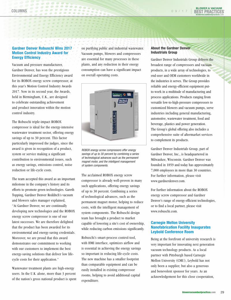
Gardner Denver Robuschi Wins 2017 Motion Control Industry Award for Energy Efficiency
Vacuum and pressure manufacturer,
Gardner Denver, has won the prestigious
Environmental and Energy Efficiency award
for its ROBOX energy screw compressor, at
this year’s Motion Control Industry Awards
2017. Now in its second year, the Awards,
held in Birmingham, U.K., are designed
to celebrate outstanding achievement
and product innovation within the motion
control industry.
The Robuschi triple-impact ROBOX
compressor is ideal for the energy-intensive
wastewater treatment sector, offering energy
savings of up to 30 percent. This factor
particularly impressed the judges, since the
award is given in recognition of a product,
system or service making a significant
contribution to environmental issues, such
as energy savings, emissions control, noise
reduction or life-cycle costs.
The team accepted this award as an important
milestone in the company's history and its
efforts to promote green technologies. Gareth
Topping, Gardner Denver Redditch’s vacuum
and blowers sales manager explained,
“At Gardner Denver, we are continually
developing new technologies and the ROBOX
energy screw compressor is one of our
latest successes. We are therefore delighted
that the product has been awarded for its
environmental and energy-saving credentials.
Moreover, we are proud that this award
demonstrates our commitment to working
with our customers to implement the best
energy-saving solutions that deliver low life-
cycle costs for their application.”
Wastewater treatment plants are high-energy
users. In the U.K. alone, more than 3 percent
of the nation’s gross national product is spent
on purifying public and industrial wastewater.
Vacuum pumps, blowers and compressors
are essential for many processes in these
plants, and any reduction in their energy
consumption can have a significant impact
on overall operating costs.
The acclaimed ROBOX energy screw
compressor is already well-proven in many
such applications, offering energy savings
of up to 30 percent. Combining a series
of technological advances, such as the
permanent magnet motor, helping to reduce
costs, with the intelligent management of
system components. The Robuschi design
team has brought a product to market
capable of lowering a site’s cost of ownership,
while reducing carbon emissions significantly.
Robuschi’s smart-process control-tool,
with HMI interface, optimizes airflow and
is essential in achieving the energy savings
so important in reducing life-cycle costs.
The new machine has a smaller footprint
than comparable equipment and can be
easily installed in existing compressor
rooms, helping to avoid additional capital
expenditure.
About the Gardner Denver Industrials Group
Gardner Denver Industrials Group delivers the
broadest range of compressors and vacuum
products, in a wide array of technologies, to
end-user and OEM customers worldwide in
the industries it serves. The Group provides
reliable and energy-efficient equipment put-
to-work in a multitude of manufacturing and
process applications. Products ranging from
versatile low-to-high-pressure compressors to
customized blowers and vacuum pumps, serve
industries including general manufacturing,
automotive, wastewater treatment, food and
beverage, plastics and power generation.
The Group’s global offering also includes a
comprehensive suite of aftermarket services
to complement its products.
Gardner Denver Industrials Group, part of
Gardner Denver, Inc., is headquartered in
Milwaukee, Wisconsin. Gardner Denver was
founded in 1859 and today has approximately
7,000 employees in more than 30 countries.
For further information, please visit
www.gardnerdenver.com.
For further information about the ROBOX
energy screw compressor and Gardner
Denver’s range of energy-efficient technologies,
or to find a local partner, please visit
www.robuschi.com.
Carnegie Mellon University Nanofabrication Facility Inaugurates Leybold Conference Room
Being at the forefront of university research is
very important for innovating next generation
vacuum technology products. As a local
partner with Pittsburgh based Carnegie
Mellon University (CMU), Leybold has not
only been a supplier, but also a generous
and benevolent sponsor for years. As an
acknowledgement for this close cooperation,
ROBOX energy screw compressors offer energy savings of up to 30 percent by combining a series of technological advances such as the permanent magnet motor, and the intelligent management of system components.
0 9 / 1 7 |
29 blowervacuumbestpractices.com
COLUMNS

the CMU community named one of the new
conference center and reception rooms
‘Leybold’ and celebrated this inauguration
with a presentation and reception held at the
CMU Nanofabrication Facility.
CMU started in 1900 with a donation of one-
million dollars from steel-pioneer Andrew
Carnegie. With some 15,000 students, they
are not on the same population scale of larger
institutions in the USA, but in achievements
they are ranked globally 23rd overall, and
for top US colleges and universities they
are ranked 19th. U.S. News & World Report
currently ranks CMU 5th in their category
Best Graduate Engineering Schools. This is
primarily due to their leading R&D in areas
of computer science, robotics, and general
engineering technologies.
As with many universities, CMU has multiple
halls with multidisciplinary labs ranging from
biology, biomedical engineering, chemistry,
electrical and computer engineering, materials
science, physics, robotics, mechanical
engineering and others. Each has its level of
vacuum needs ranging from the rough vacuum
regime to ultra-high vacuum requirements.
This includes vacuum pumping equipment
from several key suppliers, including local
partner Leybold, providing vacuum pumps,
instruments and vacuum consultation.
Leybold, like CMU, is a leader in its field. As a
pioneer in vacuum technology, celebrating 167
years, Leybold supports industry and research
throughout the world with vacuum engineering
consultation, vacuum pumps and systems, thin-
film equipment, instrumentation and related
services. CMU employs such Leybold equipment
in their new Nanofabrication Facility.
“CMU is not known as a large research
university, but instead we are recognized more
for our R&D successes in disciplines such as
computer science, engineering and robotics.
The new Nanofabrication Facility will allow
us to compete with much larger universities
for research grants in the areas of thin-film
technology, nanomanufacturing and Nano/
Micro systems,” said Gianluca Piazza, CMU
Nanofabrication Facility’s faculty director. “This
would not be possible without the generous
support of partners, such as Leybold, and other
local suppliers. We are excited to continue our
collaboration with Leybold in areas of process
development where we can use their expertise
in vacuum sciences for thin-film deposition as
well as other R&D activities throughout CMU.”
Carl Brockmeyer, Leybold USA Inc.’s general
manager adds, “We at Leybold value the
importance of thin-film and Nano/Micro
device research and we thank the CMU
community for the close association and
ongoing partnership with Leybold, and offer
our congratulations on their accomplishment
in realizing the new Nanofabrication Facility,
a premier research laboratory in the world.
My colleagues and I at Leybold are committed
to nurturing a strong partnership with
CMU for many years to come. CMU has our
commitment for continued collaboration and
support of their Nano research”.
About Leybold
Leybold is a part of the Vacuum Solution
Division within the Atlas Copco’s Compressor
Technique business area and offers a broad
range of advanced vacuum solutions for use in
manufacturing and analytical processes, as well
as for research purposes. The core capabilities
center on the development of application-and-
customer-specific systems for the creation of
vacuums and extraction of processing gases.
Fields of application are secondary metallurgy,
heat treatment, automotive industry, coating
technologies, solar and thin-films such as
displays, research & development, analytical
instruments, as well as classic industrial
processes. For more information, visit www.
leybold.com.
About Atlas Copco
Atlas Copco is a world-leading provider of
sustainable productivity solutions. The Group
serves customers with innovative compressors,
vacuum solutions and air treatment systems,
construction and mining equipment, power
tools and assembly systems. Atlas Copco
develops products and services focused on
productivity, energy efficiency, safety and
ergonomics. The company was founded in
1873, is based in Stockholm, Sweden, and
has a global reach spanning more than 180
countries. In 2016, Atlas Copco had revenues
of 11 billion euros and more than 45,000
employees. Since 1952, Atlas Copco is present
in Germany. Under the roof of two holdings
located in Essen, more than 20 production
and sales companies are gathered (February
2017). By end of 2016, The Group employed
about 3,800 people, including about 100
trainees. For more information, visit www.
atlascopco.com.
About Carnegie Mellon University – Nanofabrication
A premier research laboratory in the
College of Engineering, the Carnegie Mellon
Nanofabrication Facility is one of the most
well-equipped university-based facilities for
Matthew Moneck, Carl Brockmeyer, Gianluca Piazza as well as other CMU and Leybold colleagues unveiling the dedication plaque at the CMU Nanofab.
BLOWER & VACUUM SYSTEM INDUSTRY NEWS
| 0 9 / 1 7
30 blowervacuumbestpractices.com
COLUMNS

thin-film and Nano/Micro device development
in the United States. The Nanofab counts
approximately 10,000 square feet of class
10/100 cleanroom space where faculty, staff,
and students access the lab and collaborate
on projects originating from a multitude
of disciplines. The Nanofab also welcomes
external industry and government users.
Pfeiffer Vacuum Presents Leak Test Solutions
Leak testing plays a vital role in quality
control for a wide range of applications.
Reliable integrity packaging is crucial in the
pharmaceutical industry to guarantee sterility
and to protect drugs from any microbiological
substances, oxygen or moisture with potential
of ingressing. In the automotive industry,
leak testing ensures various components
are operating perfectly, including parts
guaranteeing the supply of gasoline. Pfeiffer
Vacuum is one of the leading providers of
vacuum technology and leak testing solutions.
The corporation benefits from more than 50
years of experience in the leak detection field.
At the Interpack and Control fairs, Pfeiffer
Vacuum presented test technologies satisfying
numerous leak detection and measuring
method requirements: leak detection using air,
leak detection with a tracer gas and optical
emission spectroscopy.
Leak Testing With Air
At the trade fairs, Pfeiffer Vacuum presented
products made by its new subsidiary Advanced
Test Concepts, Inc. (ATC) from Indianapolis,
USA. The leak detectors exhibited work on the
basis of leading leak testing technology using
air, and do not require any special tracer gases.
The devices operate according to patented
Micro-Flow technology. This technology
consists of an integrated micro sensor
working on accelerated flow. A sensitivity
of up to 5 • 10-4 mbar l/s is achieved with
this method. This technology is used in the
automotive industry, such as for testing power
trains and gearbox housings.
A specific use of the Micro-Flow sensor is
the Mass Extraction technique, which works
on the principle of rarefied gas flow. Testing
takes place in vacuum conditions to attain
higher sensitivity. This type of testing is
particularly suitable for packaging or enclosed
objects, such as pharmaceutical packaging
and electronic components. These products
require testing for watertightness. Sensitivity of
up to 5 • 10-6 mbar l/s can be achieved with
this method.
Micro-Flow and Mass Extraction technology
offer a number of advantages over other leak
testing methods working with air. The speed of
testing and their low susceptibility to ambient
changes are notable examples of this. They
also stand out due to their higher sensitivity
and accuracy, and do not require calibration
on a daily basis.
Leak Detection With Tracer Gas
The ASI 35 leak detector delivers excellent
performance in integral and localizing testing
methods, as well as combinations of the two,
using helium or hydrogen as a tracer gas. The
device combines high performance, reliability
and repeatability with extremely short cycle
times. This leak detector is designed for
demanding testing situations with minimal
background signals and enables short overall
cycle times. The robust iridium filaments also
ensure durability. Particular applications for
this device are the automotive industry but
also the field of electronic and mechanical
components, and refrigeration and air
conditioning.
Optical Emission Spectroscopy
It is important for packaging to preserve the
stable condition of particularly moisture-
sensitive medication such as dry powders
for inhalation; at the same time, it must also
prevent biological substances in the packaging
from ingressing into parenteral drugs. This
necessitates the use of high sensitivity integrity
testing. The method used by the AMI measures
leak tightness using a patented process not
requiring a tracer gas. Instead, this method
uses the existing gas mixture from the cavities
inside the packaging to perform high-sensitivity
testing over an extended measuring range. The
procedure offers great flexibility. A variety of
packaging types such as blister packs, pouches,
vials, plastic bottles and sealed parts such as
battery casings, can be tested in this way.
About Pfeiffer Vacuum
Pfeiffer Vacuum (Stock Exchange Symbol
PFV, ISIN DE0006916604) is one of the
world’s leading providers of vacuum
solutions. In addition to a full range of hybrid
and magnetically levitated turbopumps,
the product portfolio comprises backing
pumps, leak detectors, measurement and
analysis devices, components as well as
vacuum chambers and systems. Ever since
the invention of the turbopump by Pfeiffer
Vacuum, the company has stood for innovative
solutions and high-tech products used in the
Analytics, Industry, Research & Development,
Coating and Semiconductor markets. Founded Leak testing with patented Micro-Flow technology: E-PDQ
0 9 / 1 7 |
31 blowervacuumbestpractices.com
COLUMNS

To subscribe visit blowervacuumbestpractices.com
F R E E S U B S C R I P T I O NDIGITAL EDITION FREE WORLDWIDE | PRINT EDITION FREE TO U.S. SUBSCRIBERS
Poultry & Meat Packaging • Pharmaceutical & Labs • Food Processing • Wastewater Aeration
Sustainable Energy Savings with Blower & Vacuum Best PracticesBlower & Vacuum Best Practices is a technical magazine dedicated to discovering Energy Savings in industrial blower and vacuum systems and in municipal wastewater aeration blower systems. Our editorial focus is on case studies and technical articles where application and system knowledge drives technology selection, creating energy savings in projects delivering excellent ROI’s.
“ A more recent innovation is to control the aeration blowers off of total air flow instead of header pressure.”
– Julia Gass, P.E., Black & Veatch (September 2016 Issue)
“ Busch designed a customized central vacuum system for the furniture manufacturer, consisting of eight identical Mink claw vacuum pumps, each equipped with a suction capacity of 300 m3/h.”
– Uli Merkle, Busch Vacuum Pumps and Systems (feature article in July 2016 Issue)
From WWTP Aeration Blowers to Centralized Vacuum SystemsOur readers have embraced energy management practices as the next step. Our diverse key subscribers work at multi-factory manufacturing organizations and are targets to consider options such as VSD vacuum pumps in newly centralized systems. On the municipal side, over 1,000+ operators at wastewater treatment plants (WWTP’s) and blower sales channels receive the magazine. Lastly, a growing group of industrial blower and vacuum OEM design engineers are looking for technologies able to improve their machines.
“Our engineering optimizes blower packages for each field – identifying, for example, the optimal conveying velocities for over 50 types of wheat flour!”
– Todd Smith, General Manager, Coperion K-Tron (Powder Show Report in a 2016 Issue)
2017 FOCUS INDUSTRIES!
Subscribe Now!

BLOWER & VACUUM SYSTEM INDUSTRY NEWS
in 1890, Pfeiffer Vacuum is active throughout the world today. The
company employs a workforce of approximately 2,400 people and
has more than 20 subsidiaries. For more information, please visit
www.pfeiffer-vacuum.com.
ULVAC Technologies Inc. Opens California Office
ULVAC Technologies, Inc., a leading supplier of production systems,
instrumentation and vacuum pumps for technology industries, has
opened an office in Santa Clara, California. The Silicon Valley office
location gives West Coast ULVAC customers easier access to the
company's sales and service operations. It also locates company
operations closer to the Japanese headquarters and various Asian
markets. The new location will include a vacuum pump and leak
detector repair center to serve the regional customer base.
A new product line for ULVAC Technologies, Inc. is Vacuum Cooling
Systems for use in large-scale farms to extend the product shelf-life
of fresh agricultural products, flowers and meats. These systems are
also used in the processed foods industry as well, to extend the life of
products, such as airplane meals. Local demonstration capability of the
new Vacuum Cooling System is planned for the Santa Clara location.
"Much of the vacuum cooling market is located in California, and the new
Santa Clara office puts us in close proximity to major customers," said
Wayne Anderson, ULVAC Technologies, Inc.’s President/CEO. "The Santa
Clara office will serve as a business development hub within a technology-
rich region, enabling us to expand our market share in semiconductor,
MEMS and other high-technology industries.”
About ULVAC Technologies, Inc.
ULVAC Technologies, Inc. is an international corporation designing and
manufacturing systems for industrial and research applications utilizing
vacuum technology. Our products cover a broad spectrum of markets
including, equipment for semiconductors, MEMS, solar, flat-panel
display, automotive, medical, electrical, and refrigeration industries.
ULVAC Technologies uses a class-10 process development laboratory
and customer-demonstration-facility to meet the unique needs of their
different markets. ULVAC Technologies is a subsidiary of ULVAC, Inc.,
made up of 39 companies engaged in most sectors of the vacuum
industry. For more information, visit www.ulvac.com.
The new California location will include a vacuum pump and leak detector repair center to serve the regional customer base.
BLOWER & VACUUM BEST PRACTICESw w w . b l o w e r v a c u u m b e s t p r a c t i c e s . c o m
ADVERTISER INDEX
Company Page Web Site
Atlas CopcoOutside
Back Coverwww.atlascopco.us
Kaeser CompressorsInside
Front Cover www.us.kaeser.com/BVBP
Association of Energy Engineers
Inside Back Cover
www.energycongress.com
Pfeiffer Vacuum 5 www.pfeiffer-vacuum.com
Aerzen USA 7 www.aerzenusa.com
Busch Vacuum Pumps and Systems
9 www.buschusa.com
EURUS Blower 11 www.eurusblower.com
Howden Roots 19 www.howdenroots.com
WEFTEC 23 www.weftec.org
To subscribe visit blowervacuumbestpractices.com
F R E E S U B S C R I P T I O NDIGITAL EDITION FREE WORLDWIDE | PRINT EDITION FREE TO U.S. SUBSCRIBERS
Poultry & Meat Packaging • Pharmaceutical & Labs • Food Processing • Wastewater Aeration
Sustainable Energy Savings with Blower & Vacuum Best PracticesBlower & Vacuum Best Practices is a technical magazine dedicated to discovering Energy Savings in industrial blower and vacuum systems and in municipal wastewater aeration blower systems. Our editorial focus is on case studies and technical articles where application and system knowledge drives technology selection, creating energy savings in projects delivering excellent ROI’s.
“ A more recent innovation is to control the aeration blowers off of total air flow instead of header pressure.”
– Julia Gass, P.E., Black & Veatch (September 2016 Issue)
“ Busch designed a customized central vacuum system for the furniture manufacturer, consisting of eight identical Mink claw vacuum pumps, each equipped with a suction capacity of 300 m3/h.”
– Uli Merkle, Busch Vacuum Pumps and Systems (feature article in July 2016 Issue)
From WWTP Aeration Blowers to Centralized Vacuum SystemsOur readers have embraced energy management practices as the next step. Our diverse key subscribers work at multi-factory manufacturing organizations and are targets to consider options such as VSD vacuum pumps in newly centralized systems. On the municipal side, over 1,000+ operators at wastewater treatment plants (WWTP’s) and blower sales channels receive the magazine. Lastly, a growing group of industrial blower and vacuum OEM design engineers are looking for technologies able to improve their machines.
“Our engineering optimizes blower packages for each field – identifying, for example, the optimal conveying velocities for over 50 types of wheat flour!”
– Todd Smith, General Manager, Coperion K-Tron (Powder Show Report in a 2016 Issue)
2017 FOCUS INDUSTRIES!
Subscribe Now!
0 9 / 1 7 |
33 blowervacuumbestpractices.com
COLUMNS

T H E M A R K E T P L A C ETECHNOLOGY & JOBS
Blower & Vacuum Best Practices is published quarterly and mailed together with Compressed Air Best Practices®. Compressed Air Best Practices® (USPS# 17130) is published monthly except January-February combined by Smith Onandia Communications LLC, 37 McMurray Rd., Suite 106, Pittsburgh, PA 15241. Periodicals postage paid at Pittsburgh, PA and additional mailing offices. POSTMASTER: Send address changes to: Compressed Air Best Practices®, 37 McMurray Rd, Suite 106, Pittsburgh, PA 15241.
Compressed Air Best Practices® is a trademark of Smith Onandia Communications, LLC. Publisher cannot be held liable for non-delivery due to circumstances beyond its control. No refunds. SUBSCRIPTIONS: Qualified reader subscriptions are accepted from compressed air professionals, plant managers, plant engineers, service and maintenance managers, operations managers, auditors, and energy engineers in manufacturing plants and engineering/consulting firms in the U.S. Contact Patricia Smith for subscription information at tel: 412-980-9902 or email: [email protected]. REPRINTS: Reprints are available on a custom basis, contact Patricia Smith for a price quotation at Tel: 412-980-9902 or email: [email protected]. All rights are reserved. The contents of this publication may not be reproduced in whole or in part without consent of Smith Onandia Communications LLC. Smith Onandia Communications LLC. does not assume and hereby disclaims any liability to any person for any loss or damage caused by errors or omissions in the material contained herein, regardless of whether such errors result from negligence, accident, or any other cause whatsoever. Printed in the U.S.A.
BLOWER & VACUUM BEST PRACTICES www.b lower vacuumbestpract ices .com
Advertising &: Editorial
Rod Smith [email protected] Tel: 412-980-9901
Subscriptions & : Administration
Patricia Smith [email protected] Tel: 412-980-9902
A Publication of: Smith Onandia Communications LLC 37 McMurray Rd. Suite 106 Pittsburgh, PA 15241 SFI-00993
Contact Rod Smith for ad rates: [email protected], Tel: 412-980-9901
Job & Product Marketplace Advertising Information
Reach 16,000+ readers of Blower & Vacuum Best Practices Magazine with Marketplace Ads every month! Job Marketplace ads are also placed for one month on www.airbestpractices.com and promoted in our three monthly e-newsletters.
Ad dimensions are 2.36" wide x 3.91" tall. We can help you design the ads. Send us your logo, product photo, and text to [email protected]. We recommend 20-50 total words of text.
Prices are $300.00 per Job Marketplace Ad and $350.00 per Product Marketplace Ad ($300 if 6 or more ads are placed). Contact Rod Smith at [email protected] to schedule your Marketplace Ads.
| 0 9 / 1 7
34 blowervacuumbestpractices.com
COLUMNS

Other Energy Events
September 27-28, 2017 Georgia World Congress Center, Atlanta, Georgia
EXPO 2018
www.energycongress.com
Energy, Power and Facility Management, and Sustainable Energy Solutions ExpoJoin business, industrial and institutional energy users at the largest energy conference and technology expo in the U.S.
Presented By
www.energyevent.comwww.globalconevent.com
ATTENDANCE | 770.447.5083 x226
SEMINARS | 770.925.9633
EXHIBITS | 770.279.4392
CONFERENCE - SEMINARS - TRADE SHOW
Compressed_Air_WEEC_full_05-17.indd 1 5/4/17 1:39 PM

INNOVATIVE, INTELLIGENT, INDUSTRY CHANGINGA New Generation of Vacuum Pumps Superior performance and dependability,energy efficiency beyond compare, noise levels half that of the competition, and reduced environmental impact.
www.atlascopco.us – 866-546-3588