AEO Guide to Systems Architectural Design - … · delivery in the assurance of design, safety,...
29
T MU AM 06001 GU Guide AEO Guide to Systems Architectural Design Version 1.0 Issued date: 20 April 2015 Important Warning This document is one of a set of standards developed solely and specifically for use on public transport assets which are vested in or owned, managed, controlled, commissioned or funded by the NSW Government, a NSW Government agency or a Transport Agency (as defined in the Asset Standards Authority Charter). It is not suitable for any other purpose. You must not use or adapt it or rely upon it in any way unless you are authorised in writing to do so by a relevant NSW Government agency. If this document forms part of a contract with, or is a condition of approval by a NSW Government agency, use of the document is subject to the terms of the contract or approval. This document may not be current. Current standards are available for download from the Asset Standards Authority website at www.asa.transport.nsw.gov.au. © State of NSW through Transport for NSW
Transcript of AEO Guide to Systems Architectural Design - … · delivery in the assurance of design, safety,...
T MU AM 06001 GU
Guide
AEO Guide to Systems Architectural Design
Version 1.0
Issued date: 20 April 2015
Important Warning This document is one of a set of standards developed solely and specifically for use on public transport assets which are vested in or owned, managed, controlled, commissioned or funded by the NSW Government, a NSW Government agency or a Transport Agency (as defined in the Asset Standards Authority Charter). It is not suitable for any other purpose. You must not use or adapt it or rely upon it in any way unless you are authorised in writing to do so by a relevant NSW Government agency. If this document forms part of a contract with, or is a condition of approval by a NSW Government agency, use of the document is subject to the terms of the contract or approval. This document may not be current. Current standards are available for download from the Asset Standards Authority website at www.asa.transport.nsw.gov.au. © State of NSW through Transport for NSW

T MU AM 06001 GU AEO Guide to Systems Architectural Design
Version 1.0 Issued date: 20 April 2015
Standard governance
Owner: Manager Systems Engineering Process , Asset Standards Authority
Authoriser: Principal Manager Authorisation and Audit, Asset Standards Authority
Approver: Director, Asset Standards Authority on behalf of the ASA Configuration Control Board
Document history
Version Summary of Changes
1.0 First issue.
For queries regarding this document, please email the ASA at [email protected] or visit www.asa.transport.nsw.gov.au
© State of NSW through Transport for NSW

T MU AM 06001 GU AEO Guide to Systems Architectural Design
Version 1.0 Issued date: 20 April 2015
Preface The Asset Standards Authority (ASA) is an independent unit within Transport for NSW (TfNSW)
and is the network design and standards authority for defined NSW transport assets.
The ASA is responsible for developing engineering governance frameworks to support industry
delivery in the assurance of design, safety, integrity, construction, and commissioning of
transport assets for the whole asset life cycle. In order to achieve this, the ASA effectively
discharges obligations as the authority for various technical, process, and planning matters
across the asset life cycle.
The ASA collaborates with industry using stakeholder engagement activities to assist in
achieving its mission. These activities help align the ASA to broader government expectations
of making it clearer, simpler, and more attractive to do business within the NSW transport
industry, allowing the supply chain to deliver safe, efficient, and competent transport services.
The ASA develops, maintains, controls, and publishes a suite of standards and other
documentation for transport assets of TfNSW. Further, the ASA ensures that these standards
are performance-based to create opportunities for innovation and improve access to a broader
competitive supply chain.
This AEO Guide to Systems Architectural Design guidance has been developed on the
technical processes of AS/NZS/ISO/IEC 15288:2008 by the Asset Standards Authority Systems
Engineering team, reviewed by a consultative group containing members from Transport for
NSW stakeholder groups, and approved by the ASA Configuration Control Board.
This AEO Guide to Systems Architectural Design aims to provide TfNSW and supplier
organisations with guidance in the synthesis and development of system level requirements into
an effective system architecture, upon which a robust system design can be based.
This guide is placed within the broader context of systems engineering as defined in the ASA
standard T MU AM 06006 ST Systems Engineering.
This guide is the first issue.
© State of NSW through Transport for NSW Page 3 of 29
T MU AM 06001 GU AEO Guide to Systems Architectural Design
Version 1.0 Issued date: 20 April 2015
Table of contents 1. Introduction .............................................................................................................................................. 5
2. Purpose .................................................................................................................................................... 5 2.1. Scope ..................................................................................................................................................... 5 2.2. Application ............................................................................................................................................. 5
3. Reference documents ............................................................................................................................. 6
4. Terms and definitions ............................................................................................................................. 7
5. System architectural design ................................................................................................................... 8 5.1. System architectural design inputs ...................................................................................................... 10 5.2. System architectural design activities .................................................................................................. 10 5.3. System architectural design outputs .................................................................................................... 15 5.4. System of systems ............................................................................................................................... 15 5.5. Methods and modelling techniques ..................................................................................................... 18 5.6. Modelling languages ............................................................................................................................ 19 5.7. The railway architecture framework ..................................................................................................... 19
Appendix A Example of logical architecture, power trains ................................................................ 24
Appendix B Example of physical architecture, power trains ............................................................. 25
Appendix C Example of physical architecture, railway bridge .......................................................... 26
Appendix D Example of physical architecture, railway track ............................................................. 27
Appendix E Example of BIM, railway bridge ........................................................................................ 28
Appendix F Example of system context diagram, railway line .............................................................. 29
© State of NSW through Transport for NSW Page 4 of 29

T MU AM 06001 GU AEO Guide to Systems Architectural Design
Version 1.0 Issued date: 20 April 2015
1. Introduction The Asset Standards Authority (ASA) has established an engineering framework based on
engineering principles and methods that include building architecture, systems architecture
design and management. Organisations undertaking systems architectural design should
operate within this framework to manage engineering activities undertaken on behalf of
Transport for New South Wales (TfNSW) over the whole asset life cycle.
T MU MD 00009 ST AEO Authorisation Requirements states the following mandatory
requirement for systems architectural design:
"A design Authorised Engineering Organisation shall demonstrate that it has arrangements to
manage the synthesis and development of system level requirements into credible system
architecture".
2. Purpose This document describes the systems architectural design process and the key responsibilities
that an AEO should hold in managing systems architectural design.
The AEO Guide to Systems Architectural Design further develops the brief guidance described
in TS 10504 AEO Guide to Engineering Management.
2.1. Scope This systems architectural design guidance has been based on an interpretation of the system
architecture technical process of AS/NZS/ISO/IEC 15288:2008 for practical application on
transport projects. It focuses on the ASA's representation of systems architectural design in the
context of work performed by AEOs on behalf of TfNSW.
2.2. Application This document is primarily intended for application by organisations conducting systems
architectural design activities related to the engineering services provided on behalf of TfNSW.
The guidance provided in this document applies to organisations that are involved with the
development of the project business requirements specification (BRS) and organisations that
translate the project BRS into system requirement specification (SRS) and the supporting
project architecture.
This includes organisations responding to tenders in addition to organisations applying to be
pre-registered as an AEO in order to be considered for tendering for TfNSW work.
This guide provides general recommendations for prospective and existing AEOs and is tailored
to address high-level systems architectural design requirements.
© State of NSW through Transport for NSW Page 5 of 29

T MU AM 06001 GU AEO Guide to Systems Architectural Design
Version 1.0 Issued date: 20 April 2015
This guide is applicable to project work carried out by disciplines including systems engineering,
electrical engineering, mechanical engineering, civil engineering, communications engineering
and architecture.
This guide is applicable to organisations involved in planning across all modes of transport and
for project development and delivery.
This guide recognises that the application of system architecture design principles carry
different meaning to different transport modes, asset or discipline groups, and organisations.
The intent is to define key common principles that can be applied to these different domains.
The principles described within this guide are to be scaled and tailored to suit the level of
novelty, complexity, scale and risk associated with each project.
Note: The application of all elements of this guide should be carefully considered to
ensure the appropriate level of rigour, and to ensure that value for money and safety
are achieved.
3. Reference documents International standards
ISO/IEC 19501 Information technology - Open Distributed Processing - Unified Modelling
Language (UML) Version 1.4.2
Australian standards
AS/NZS ISO/IEC 15288 Systems and software engineering - System life cycle processes
AS/NZS ISO/IEC 15289 Systems and software engineering - Content of systems and software
life cycle process information products (Documentation)
AS/NZS ISO/IEC/IEEE 42010 Systems and software engineering - Architecture description
Transport for NSW standards
T MU AM 02001 ST Asset Information Management
T MU AM 06006 ST Systems Engineering Standard
T MU MD 00009 ST AEO Authorisation Requirements
TS 10504 AEO Guide to Engineering Management
Other reference documents
INCOSE TP-2003-002-03.2.2 Systems Engineering Handbook. A Guide for System Life Cycle
Processes and Activities
SEBoK v1.0 Guide to the Systems Engineering Body of Knowledge (SEBoK) version 1.0
© State of NSW through Transport for NSW Page 6 of 29

T MU AM 06001 GU AEO Guide to Systems Architectural Design
Version 1.0 Issued date: 20 April 2015
The UK Ministry of Defence Architecture Framework (MODAF)
TRAK The Railway Architecture Framework Metamodel
4. Terms and definitions The following terms and definitions apply in this document:
3D three dimensional
AEO Authorised Engineering Organisation means a legal entity (which may include a
Transport Agency as applicable) to whom the ASA has issued an ASA Authorisation
ASA Asset Standards Authority
ASA authorisation an authorisation issued by the ASA to a legal entity (which may include a
Transport Agency as applicable) which verifies that it has the relevant systems in place to carry
out the class of Asset life cycle work specified in the authorisation, subject to any conditions of
the authorisation. The issue of ASA Authorisation confers the status of 'authorised engineering
organisation' or AEO on the entity.
assurance a positive declaration intended to give confidence
asynchronous not happening at the same frequency
BIM building information modelling
BRS business requirements specification
compliance the state or fact of according with, or meeting, rules or standards
COTS commercial off the shelf goods and services that can be bought and used
CAD computer aided design
derived requirement a need refined from a higher level need
emergent property a characteristic from the arrangement and interaction between system
elements, which may not be a characteristic of any individual element
intended property a planned characteristic of a system element
metamodel a model of a model
non-functional requirement specifies how a system is supposed to be
responsibility a duty or obligation to satisfactorily perform or complete a task (assigned by
someone, or created by one's own promise or circumstances) that one must fulfil, and which
has a consequent penalty for failure. Responsibility can be delegated
review a method to provide assurance by a competent person that an engineering output
complies with relevant standards and specific requirements, is safe and fit for purpose.
© State of NSW through Transport for NSW Page 7 of 29
T MU AM 06001 GU AEO Guide to Systems Architectural Design
Version 1.0 Issued date: 20 April 2015
SME subject matter expert a person assessed or recognised as having a high level of
competence (including knowledge, skills and practical experience) in a particular field or
discipline. This is typically a professional head of discipline or technical director
SQE safety, quality and environment
SRS system requirements specification
supplier a supplier of engineering services or products. Defined as an 'applicant' until such time
as it has been granted AEO status, after which it is referred to as an AEO.
synchronous happening at the same frequency
SysML systems modelling language
TfNSW Transport for New South Wales
UML Unified Modelling Language
use case an interaction of a stakeholder and a system to achieve a goal
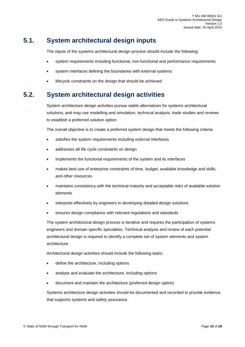
5. System architectural design Systems architectural design is the translation of system functional, non-functional and
performance requirements into a structured, clear and consistent framework of grouped and
allocated functions that can be interpreted by designers at the system and subsystem level. It
includes the eventual selection of the types of system elements, their characteristics, and their
arrangement that meet the stakeholder requirements, without specifying the detailed design
solution. Systems architectural design, while similar in many aspects relating to providing a
design framework, is a different process to traditional building architectural design.
Figure 1 shows the architectural design process including the process inputs, design activities
and process outputs.
© State of NSW through Transport for NSW Page 8 of 29

T MU AM 06001 GU AEO Guide to Systems Architectural Design
Version 1.0 Issued date: 20 April 2015
Figure 1 - Architectural design process
ISO/IEC 15288:2008 states:
“The purpose of the (system) Architectural Design Process is to synthesize a solution that
satisfies system requirements.”
Some key roles of the system architecture are as follows:
• provide structure and grouping to functional and performance requirements
• provide a framework to allocate functions to systems and subsystems
• provide a visual reference upon which to base the detailed system design solution
• provide a basis for systems modelling and analysis, including RAM, safety and
performance
• establish the physical and functional interfaces within, and at the boundary of the system
• help management of complexity, uncertainty and risk including safety and environment and
sustainability considerations
• support evolution, scaling and migration of systems and their configuration over time
• provide a decision-making and options trade study basis
• provide a basis for development of detailed designs
Inputs Outputs
System requirements
System interfaces
Design Constraints
System elements
Interface requirements
Verification and integration
basis
Architectural design
baseline
Architectural design activities
Define the architecture
Analyse and evaluate the architecture
Document and maintain the architecture
User requirements
© State of NSW through Transport for NSW Page 9 of 29
T MU AM 06001 GU AEO Guide to Systems Architectural Design
Version 1.0 Issued date: 20 April 2015
5.1. System architectural design inputs The inputs of the systems architectural design process should include the following:
• system requirements including functional, non-functional and performance requirements
• system interfaces defining the boundaries with external systems
• lifecycle constraints on the design that should be achieved
5.2. System architectural design activities System architecture design activities pursue viable alternatives for systems architectural
solutions, and may use modelling and simulation, technical analysis, trade studies and reviews
to establish a preferred solution option.
The overall objective is to create a preferred system design that meets the following criteria:
• satisfies the system requirements including external interfaces
• addresses all life cycle constraints on design
• implements the functional requirements of the system and its interfaces
• makes best use of enterprise constraints of time, budget, available knowledge and skills,
and other resources
• maintains consistency with the technical maturity and acceptable risks of available solution
elements
• interprets effectively by engineers in developing detailed design solutions
• ensures design compliance with relevant regulations and standards
The system architectural design process is iterative and requires the participation of systems
engineers and domain specific specialists. Technical analysis and review of each potential
architectural design is required to identify a complete set of system elements and system
architecture.
Architectural design activities should include the following tasks:
• define the architecture, including options
• analyse and evaluate the architecture, including options
• document and maintain the architecture (preferred design option)
Systems architecture design activities should be documented and recorded to provide evidence
that supports systems and safety assurance.
© State of NSW through Transport for NSW Page 10 of 29

T MU AM 06001 GU AEO Guide to Systems Architectural Design
Version 1.0 Issued date: 20 April 2015
5.2.1. Define the architecture Figure 2 shows the activities for defining the system architecture.
Figure 2 Activities in defining the system architecture
The approach taken to define the system architecture depends on whether the system to be
designed is independent of any previous systems, or is based on existing products or services.
Note: The approach described here applies to new system architectures. For systems
being developed around existing architectures, the processes should be tailored
accordingly.
Systems architectural design comprises the following two stages:
• logical architectural design
• physical architectural design
Logical architectural design includes functional, behavioural and temporal (time-based process)
architectures and are described with views, corresponding to viewpoints.
Functional architecture is a set of functions and their sub-functions that defines the
transformations of input flows into output flows performed by the system to achieve its
objectives. An example of functional architecture view is use cases as shown in Figure 8.
Define logical designs
Capture sequencing and
interactions
Partition functions and allocate to
systems elements
Generate requirements
Evaluate existing solutions
Identify and define interfaces and
interactions
Define verification and validation criteria for the
system elements
© State of NSW through Transport for NSW Page 11 of 29

T MU AM 06001 GU AEO Guide to Systems Architectural Design
Version 1.0 Issued date: 20 April 2015
Behavioural architecture is an arrangement of functions and their sub-functions and interfaces
which defines the execution sequencing, conditions for control or data-flow and the performance
requirements to satisfy the system requirements
An example of logical architectural design is provided in Appendix A.
The purpose of the physical architectural design process is to define, select and synthesise a
system architecture that supports the logical architecture and satisfies the system requirements.
Once a logical architecture is defined, physical elements are identified that supports functional,
behavioural and temporal features and expected properties of the system deduced from
non-functional system requirements. These physical elements relate to asset types and
products, and reflect the proposed physical solution.
The system is established based on the physical architecture from systems, elements, the
physical interfaces between these elements and external elements.
Examples of physical architectural designs that are used in practice in the rail transport domain
are provided in Appendix B and Appendix C.
A system element is a discrete part of the system that is implemented to fulfil design properties.
They are hardware, software, humans, processes or naturally occurring entities. A physical
interface connects two system elements together. Complex systems are composed of many
physical or non-physical parts and may be structured in several layers of systems and system
elements.
As part of defining, selecting and synthesising a system physical architecture, system and
element properties are developed which are either an intended property of the system or
element design, or an emergent property.
A design property is a characteristic obtained during system architecture and design. The
property arises through the assignment of non-functional requirements, estimates, analysis
calculations, simulations of a specific aspect, or through the definition of an existing element
associated with a system element, a physical architecture or a physical interface. If the
designed element complies with a requirement, the design property should relate to the
requirement.
An emergent property is a property that emerges from the arrangement and interaction between
system elements, that is the integrated system, but may not be a property of any individual
subsystem or element on its own. System elements interacting amongst themselves may create
desirable or undesirable emergent properties at the system level.
For example an improvement to the signalling element property of ‘headway’ from three minutes
to two minutes, while not concurrently improving the traction power supply element property of
‘feed section current’ from 5000 Amps to 8000 Amps.
© State of NSW through Transport for NSW Page 12 of 29

T MU AM 06001 GU AEO Guide to Systems Architectural Design
Version 1.0 Issued date: 20 April 2015
This could lead to the undesirable emergent property of too many trains in the feed section,
resulting in the protection system disconnecting the traction supply to the feed section, and
leading to serious delays and traffic disruption.
The activities for defining the system architecture are outlined in the following steps:
1. Define the appropriate logical architectural designs.
2. Capture the logical sequencing and interaction of system functions or logical elements.
3. Partition the system functions identified through the requirements analysis process and
allocate them to elements of the system architecture.
4. Generate derived requirements as needed for these allocations.
5. Evaluate COTS solutions for suitability.
6. Identify and define the interfaces and intended and unintended interactions of system
elements (including human elements, noise, vibration, heat, light and electromagnetic
interference of the system) with external and enabling systems.
7. Define the verification and validation criteria against the requirements for the identified
system elements.
5.2.2. Analyse and evaluate the architecture Figure 3 shows the principal activities for analysing and evaluating the architecture.
Figure 3 - Activities in analysing and evaluating the architecture
Analyse and evaluate is done through quantitative assessment to identify the most efficient
system architecture, which represents the optimised design after trade-offs are made.
System analysis provides a rigorous approach to technical decision making. It should be used
at decision points, such as stage gate reviews, to determine compliance with systems
requirements. It includes analysis techniques such as modelling and simulation, cost analysis,
technical risk analysis and effectiveness studies.
Analyse design to establish
requirements
Determine requirements
allocation
Consider task analysis, human
capabilities, actions, errors and
performance
Evaluate elements for compatibility
Evaluate alternative design solutions
Perform effectiveness
assessments, trade-off and risk analyses
© State of NSW through Transport for NSW Page 13 of 29

T MU AM 06001 GU AEO Guide to Systems Architectural Design
Version 1.0 Issued date: 20 April 2015
The activities for analysing and evaluating the architecture are described in the following steps:
1. Analyse the resulting architectural design to establish requirements for each element. The
requirements could include physical, performance, behavioural durability and sustainable
service characteristics.
2. Determine which system functional and non-functional requirements are allocated to
human operators or users, as opposed to hardware and software allocation.
3. Consider task analysis, the limitations of human capabilities, human actions critical to
safety, the potential consequences of human error and the integration of human
performance into systems and their operation.
4. Evaluate COTS elements for compatibility with the design, and ability to be integrated into
the system solution while achieving the emergent properties.
5. Evaluate alternative architecture solutions, model each alternative architecture solution
against the specifications expressed in the stakeholder and system requirements.
6. Perform effectiveness assessments, trade-off analysis and risk analysis taking into account
of any adverse emergent properties resulting from element and system interactions. This
should lead to the realisation of a feasible, effective, stable optimised design.
5.2.3. Document and maintain the architecture Figure 4 shows a high level view of the activities for documenting and maintaining the
architecture.
Figure 4 - Activities to document and maintain the architecture
Specify baseline
Document design and decisions
Establish and maintain
requirements traceability
© State of NSW through Transport for NSW Page 14 of 29

T MU AM 06001 GU AEO Guide to Systems Architectural Design
Version 1.0 Issued date: 20 April 2015
Documenting and maintaining the architecture is done by performing the following steps:
1. Specify the selected architectural design baseline in terms of its functions, performance,
operational behaviour, interfaces and constraints.
2. Document and maintain the architectural design and decisions agreed on the baseline
architectural design.
3. Establish and maintain the traceability between requirements and system elements.
5.3. System architectural design outputs The output of the systems architectural design process should be a synthesised solution that
meets the system requirements. Evidence of the systems architectural design activities should
be recorded. The outputs of the systems architectural design process should include the
following:
• an architectural design baseline (functional initially, and physical eventually)
• a configured arrangement of system elements which satisfy the system requirements
Traceability of allocated requirements to the systems elements of the architectural design
should be recorded.
• interface requirements that are incorporated in the systems architectural design
• a basis for verifying and integrating the defined system elements
Refer to T MU AM 02001 ST Asset Information Management for requirements relating to asset
information management for assets owned by TfNSW across the asset life cycle.
5.4. System of systems Many modern transport systems comprise thousands of physical and intangible parts structured
in several layers of systems and system elements, referred to as ‘systems of systems’.
Therefore, system architectural design needs to be considered at each of these multiple levels
of systems and system elements.
The number of elements in the decomposition of one system is limited to only a few in order to
facilitate the ease of analysing and synthesising the system; a common guideline is ‘five plus or
minus two’ elements.
For example a railway system may consist of the following seven elements - trains, stabling
yard, fleet depot, track/civil, traction power, signalling and telecommunications.
For complex systems, an architectural design needs to be devised to meet the
system-of-systems (highest) level of requirements for function, performance, constraints and
external interfaces. The elements of that architecture are subsequently allocated with functions,
© State of NSW through Transport for NSW Page 15 of 29

T MU AM 06001 GU AEO Guide to Systems Architectural Design
Version 1.0 Issued date: 20 April 2015
and each of these architecture elements themselves has sub-architectures to design and
document.
Eventually, at the lowest level of architectural design, the transition into physical implementation
takes place where the physical design solutions are devised for all of the unit and configuration
item levels of the final deliverable solution.
A diagram representing multiple levels of architectural design is shown in Figure 5.
Some of the activities undertaken in systems architectural design of a system of systems
include the following:
• define high level system context
• define system boundary
• identify and analyse external interfaces
• allocate functions to physical elements
• define generic systems architecture
• allocate system functional requirements to elements
• define element architecture
Systems design comprises multiple levels of architectural design. The levels continue until the
physical implementation solution is reached. An individual system element has its own
architectural design that forms a part of the overall system design.
© State of NSW through Transport for NSW Page 16 of 29

T MU AM 06001 GU AEO Guide to Systems Architectural Design
Version 1.0 Issued date: 20 April 2015
Figure 5 - Multiple levels of architectural design
Multiple levels of architectural design
Architectural design
Architectural design
Architectural design
Architectural design
Architectural design
Architectural design
Architectural design
System element
requirements
System element
requirements
Physical architecture
Logical architecture
System requirements
Architectural design
System element
requirements
System element
requirements
Physical architecture
Logical architecture
System requirements
Architectural design
System element
requirements
System element
requirements
Physical architecture
Logical architecture
System requirements
Architectural design
System element
requirements
System element
requirements
Physical architecture
Logical architecture
System requirements
System element
requirements
Stakeholder requirements
© State of NSW through Transport for NSW Page 17 of 29

T MU AM 06001 GU AEO Guide to Systems Architectural Design
Version 1.0 Issued date: 20 April 2015
5.5. Methods and modelling techniques A range of modelling techniques is available which can assist in the development of the system
architectural design including both logical and physical architectural design modelling methods.
Some examples of system architectural models which may be familiar to the transport sector
include the following:
• single line diagrams; for example, high voltage network switching diagrams
• transmission network schematic, for example, fixed backbone fibre links and nodes
• signal interlocking block diagrams, for example, office and field-based systems
• building architectural drawings, for example, the 'traditional' building architects view
• building information modelling, for example, the structure and services of a building
Logical architectural design uses modelling techniques that are grouped by the following types
of models and are most appropriate to software-based systems architecture designs:
• functional models
• use case models
• dynamic models
Physical architectural design uses modelling techniques that are grouped by the following types
of models:
• physical block diagrams
• block definition diagrams
• internal block diagrams
• building architecture drawings and 3D CAD models (including BIM)
• concept or 30% designs for civil structures
Systems analysis uses modelling techniques that are grouped by the following types of models:
• physical models - scale models allowing simulation of physical phenomena
• behavioural models - used to simulate the behaviour of the system. For example;
enhanced functional flow block diagrams, state-charts, state machine diagrams (SysML)
• analytical models - used to establish values of estimates
© State of NSW through Transport for NSW Page 18 of 29
T MU AM 06001 GU AEO Guide to Systems Architectural Design
Version 1.0 Issued date: 20 April 2015
5.6. Modelling languages A modelling language is an artificial language that is used to express information or knowledge
or systems in a structure that is defined by a consistent set of rules. The rules are used for
unambiguous interpretation of the meaning of components in the structure.
The unified modelling language (UML) is a general-purpose software modelling language that is
an industry standard for specifying software-intensive systems which is supported by 13
different diagram techniques, and has widespread tool support.
The systems modelling language (SysML) is a general-purpose modelling language for systems
engineering applications. It supports the specification, analysis, design, verification and
validation of a broad range of systems (including but not limited to software) and
systems-of-systems. SysML includes an open source license for distribution and is defined as
an extension of a subset of UML.
Both UML and SysML are industry standard modelling languages for the development of
system architectural design and are a basis for ISO/IEC 15289, ISO/IEC 19501 and
ISO/IEC/IEEE 42010.
Note: While the UML language was developed for the software industry, its use is
being extended into non-software engineering industries. The principles and rigour it
brings to modelling and analysing complex integrated transport systems is
encouraged.
5.7. The railway architecture framework The ASA has developed a railway functional architecture model based on the railway
architecture framework or TRAK, developed for the Rail Safety Standards Board (RSSB) in the
UK.
The TRAK metamodel is a system-oriented architecture framework that started as an adaptation
to and simplification of the British Ministry of Defence Architectural Framework (MODAF), but is
now a standalone architecture framework for application in the transport industry.
TRAK maintains five different viewpoints or perspectives to describe concepts ranging from
enterprise goals to the detailed working solution. These viewpoints are as follows:
• Enterprise, including enterprises, goals and capabilities
• Concept, including nodes, needs and concept activities to support enterprise capabilities
• Solution, including resources, functions and interactions
• Management
• Procurement
© State of NSW through Transport for NSW Page 19 of 29

T MU AM 06001 GU AEO Guide to Systems Architectural Design
Version 1.0 Issued date: 20 April 2015
TRAK assists in identifying enterprise and project scope and boundaries, interfaces and
applicable standards.
Before starting a system architecture design, an AEO should contact the ASA to identify the
status of any rail system-oriented architecture models which should be used to assist in the
design or modification of any rail systems. One of the key benefits of developing architecture
models is to assist in defining and planning network changes and upgrades during the 'concept’
and ‘specify’ stages of the system life cycle. It assists with clearly articulating system functional
requirements to assist in business case, operational concepts, stakeholder requirements and
investment planning.
A part of the architecture model developed by ASA for stations and interchanges is shown in
Figure 6 and for track it is shown in Figure 7. The modelling shows how the enterprise
capabilities for stations and interchanges are supported by concept activities. These concept
activities are realised by solution functions. In turn these solution functions are performed by
physical items.
For example, a systems architectural model of stations and interchanges could contain the
following capability statements:
• services to meet current and future capability
• safety regulation and authorisation
• meet customer expectations
• infrastructure development
These capability statements are supported by infrastructure management that itself is partly
supported by infrastructure provision. The infrastructure provision comprises a number of
concept activities including support safe and efficient customer circulation.
The concept activity support safe and efficient customer circulation is realised through solution
functions including facilitate smooth pedestrian flows between spaces that is partly fulfilled by
the physical provision of lifts, escalators or stairs.
In this example, the architecture shows how a physical item such as ‘stairs’ provides a part
solution to fulfilling the business capability statements.
© State of NSW through Transport for NSW Page 20 of 29

T MU AM 06001 GU AEO Guide to Systems Architectural Design
Version 1.0 Issued date: 20 April 2015
Figure 6 - System architectural model sample - Stations and interchanges
© State of NSW through Transport for NSW Page 21 of 29

T MU AM 06001 GU AEO Guide to Systems Architectural Design
Version 1.0 Issued date: 20 April 2015
Figure 7 - System architectural model sample - Track
© State of NSW through Transport for NSW Page 22 of 29

T MU AM 06001 GU AEO Guide to Systems Architectural Design
Version 1.0 Issued date: 20 April 2015
Figure 8 - Use case sample - Heavy rail
© State of NSW through Transport for NSW Page 23 of 29

T MU AM 06001 GU AEO Guide to Systems Architectural Design
Version 1.0 Issued date: 20 April 2015
Appendix A Example of logical architecture, power trains Figure 9 is an example of logical architecture for the supply of power to trains. The example shows the logical entities involved in the supply of
power and the associations between these logical entities. The source bulk power function supplies power to the distribute power function to
distribute to the necessary areas. The reduce voltage function then reduces the voltage to the necessary voltage for use by the trains and the
convert voltage function supplies direct current for use by the trains. The control traction power function ensures the supply of the direct current and
the feed traction power to trains function sends the power to the necessary train areas.
Note that in this model, no physical solution is provided; only the functional requirements are defined. This allows the solution provider or developer
to interpret the functions and determine one or more potential solutions. This approach stimulates innovative thinking in solution engineering and
removes potential performance constraints based on existing technology solutions that may no longer be capable of meeting future performance
capabilities.
Source bulk power Distribute power Reduce voltage Convert voltage Feed traction power to trains
Control traction power
Figure 9 - Functional flow block diagram power trains example
© State of NSW through Transport for NSW Page 24 of 29

T MU AM 06001 GU AEO Guide to Systems Architectural Design
Version 1.0 Issued date: 20 April 2015
Appendix B Example of physical architecture, power trains Figure 10 is an example of physical architecture for the supply of power to trains. The example shows the physical entities involved in the supply of
power and the relationships between these physical entities. The power generator produces the power that is transmitted by high voltage aerial
lines on poles or by high voltage underground cables. The transformers then reduce the voltage to the necessary voltage for use by the trains and
the rectifiers convert it to direct current. Circuit breakers limit the current drawn by the system and the supervisory control and data acquisition
monitors and controls the supply of the power. The dc cables supply power to the catenary and the contact wire that are mounted on overhead
wiring structures.
Figure 10 - Physical architecture power trains example
Power generator
High voltage aerial lines
Wooden piles
High Voltage Underground
cables
Transformers Rectifiers Circuit breakers dc cables Catenary Contact
wire
Supervisory control and data acquisition
Overhead wiring
structures
© State of NSW through Transport for NSW Page 25 of 29

T MU AM 06001 GU AEO Guide to Systems Architectural Design
Version 1.0 Issued date: 20 April 2015
Appendix C Example of physical architecture, railway bridge Figure 11 is an example of physical architecture for a railway bridge. The example shows the physical entities involved in the railway bridge and the
relationships between these physical entities.
Figure 11 - Physical architecture example, railway bridge
CulvertsPiles
Concrete ReinforcementGirdersSteelworkCabling
Water proofing
SignageLighting Drainage
© State of NSW through Transport for NSW Page 26 of 29

T MU AM 06001 GU AEO Guide to Systems Architectural Design
Version 1.0 Issued date: 20 April 2015
Appendix D Example of physical architecture, railway track Figure 12 is an example of physical architecture for a railway track. The example shows the physical entities involved in the railway track and the
relationships between these physical entities.
Figure 12 - Physical architecture example, railway track
Rail
Sleepers
Ballast
Fastening
Bonding
Subgrade
Earthing
Underline Crossing Conduit
Drainage
© State of NSW through Transport for NSW Page 27 of 29

T MU AM 06001 GU AEO Guide to Systems Architectural Design
Version 1.0 Issued date: 20 April 2015
Appendix E Example of BIM, railway bridge Figure 13 is an example of the Building Information Modelling for a railway bridge. It shows the 3D spatial information, the 4D schedule information,
the 5D cost information and the 6D lifecycle management Information.
Figure 13 - BIM example, railway bridge
6D
3DSpatial information
ID Task Name FinishFeb 2015
18 19 20
1 18/02/201518/02/2015 Task 1
2 18/02/201518/02/2015 Task 2
Start
4D
Schedule information
Cost information5D
Lifecycle management information
© State of NSW through Transport for NSW Page 28 of 29

T MU AM 06001 GU AEO Guide to Systems Architectural Design
Version 1.0 Issued date: 20 April 2015
Appendix F Example of system context diagram, railway line Figure 14 is an example of the system context diagram for a railway link. The example shows the boundaries between the system, interacting
systems and the environment.
Figure 14 - System context diagram example, railway line
External Organisations
Train controlBus
interchangesRail
Management Centre
Operations
Maintenance
PassengersCommercial rentals
Emergency services
Rolling stock
Public roads, footpaths
Public Utilities
Permanent way
Security
CommunicationsRailway
Line System
Interchange Stations
© State of NSW through Transport for NSW Page 29 of 29