AEE: Proposed Peat Extraction - nrc.govt.nz · The principle outcome of this AEE is to provide a...
66
GEOTECHNICAL | ENVIRONMENTAL | STORMWATER | HYDROGEOLOGY HYDROLOGICAL & HYDROGEOLOGICAL ASSESSMENT AEE: PROPOSED PEAT EXTRACTION NORTON ROAD, KAIMAUMAU, FAR NORTH DISTRICT PREPARED FOR RESIN & WAX HOLDINGS LTD 16325 18 AUGUST 2017
Transcript of AEE: Proposed Peat Extraction - nrc.govt.nz · The principle outcome of this AEE is to provide a...

GEOTECHNICAL | ENVIRONMENTAL | STORMWATER | HYDROGEOLOGY
HYDROLOGICAL & HYDROGEOLOGICAL ASSESSMENT
AEE: PROPOSED PEAT EXTRACTION
NORTON ROAD, KAIMAUMAU, FAR NORTH DISTRICT
PREPARED FOR RESIN & WAX HOLDINGS LTD
16325 18 AUGUST 2017
Job Ref: 16325
AEE: Proposed Peat Extraction | Norton Road, Kaimaumau, Far North District
18 August 2017 | Rev. C
Document Control Record
Document Prepared By:
Soil & Rock Consultants
Level 1, 131 Lincoln Road
Henderson
PO Box 21 424
Henderson
Waitakere 0650
T 09 – 835 1740
www.soilandrock.co.nz
Document Control
Document Title Hydrological & Hydrogeological Assessment
Project AEE: Proposed Peat Extraction Project Number 16325
Client Resin & Wax Holdings Ltd Revision Rev. C
Prepared By Sean Berry
Hydrogeologist / Engineering Geologist, MSc (Geology)
Reviewed By Zeljko Viljevac
Senior Hydrogeologist / Engineering Geologist, MSc (Geology)
Authorised By Zeljko Viljevac
Senior Hydrogeologist / Engineering Geologist, MSc (Geology)
Revision History
Rev Date Amendment Prepared By Reviewed By Authorised By
A 15/08/16 Draft Issued to Client S. Berry Z. Viljevac
B 01/09/16 Draft Issued to Client S. Berry Z. Viljevac
C 18/08/17 AEE: Proposed Peat Extraction S. Berry Z. Viljevac Z. Viljevac.
DISTRIBUTION:
[Name] [Company (if Applicable)/ Client] [PDF / Hard Copy]
SRC File Soil & Rock Consultants PDF
Narendra Deva Resin & Wax Holdings Ltd PDF
John Cunningham Resin & Wax Holdings Ltd PDF
COPYRIGHT:
The information presented in this document is the property of Soil & Rock Consultants.
Use or copying of this document in whole or in part without the previous permission of Soil & Rock Consultants implies a breach of copyright.
Soil & Rock Consultants is the trading entity of Geotechnical Engineering Ltd

Job Ref: 16325
AEE: Proposed Peat Extraction | Norton Road, Kaimaumau, Far North District
18 August 2017 | Rev. C
Table of Contents
1 Introduction 1
1.1 Project Brief and Scope 1
1.2 Limitations 2
2 Site Description 2
PART A – DESKTOP REVIEW 6
3 Geology 6
4 Project Background 7
4.1 Available Information 7
4.1.1 Kauri Resin Extraction and Land Reclamation Project (Cuttriss et al, 1979) 8
4.1.2 Options for Managing the Kaimaumau Wetland, Northland, New Zealand (Hicks et al, 2001) 10
4.2 Proposed Operations 10
4.3 Area of Operations 11
4.4 Potential For Adverse Effects 12
5 Territorial Authority Regulations 13
5.1 Northland Regional Council 13
5.2 Far North District Council 14
6 Site Walkover 15
7 Hydrology 16
7.1 Hydrology Discussion 18
8 Desktop Hydrogeological Assessment 18
8.1 Desktop Hydrogeology Discussion 21
PART B – DETAILED ASSESSMENT 23
9 Field Investigation 23
10 Catchment Connectivity 23
10.1 Discussion Catchment Connectivity 24
11 Hydraulic Characterisation 25
11.1 Hydraulic Conductivity 26
11.1.1 Slug Testing 26
11.1.2 Laboratory Testing 26
11.1.3 Summary of Hydraulic Conductivity 27
11.2 Additional Parameters 27
11.3 Hydraulic Characterisation Discussion 28
12 Detailed Hydrogeology 29
12.1 Detailed Hydrogeology Discussion 32
13 Environmental Screening 32
13.1 PASS Field Screening 32
13.2 Baseline Monitoring 34
14 Recommendations 38
Appendices
Appendix A: Hydraulic Conductivity Analyses
Job Ref: 16325
AEE: Proposed Peat Extraction | Norton Road, Kaimaumau, Far North District
18 August 2017 | Rev. C | Page 1
1 Introduction
1.1 Project Brief and Scope
Soil & Rock Consultants have been engaged by Resin & Wax Holdings Ltd to undertake a hydrological & hydrogeological
assessment and Assessment of Environmental Effects (AEE) at Norton Road, Kaimaumau, Far North District in connection with
dewatering associated with the proposed commercial extraction of peat. The proposed peat extraction, and associated
dewatering is proposed to cover discrete 5-40ha blocks of land within the Kaimaumau Peatlands, and is covered under Mineral
Permit Number 60384.01.
Background project information supplied by Resin & Wax Holdings Ltd indicate that the proposed extraction area is:
• Within an approximately 950ha land holding of the Ngai Takoto iwi;
• Adjacent to an approximately 700ha Department of Conversation (DoC) reserve area;
• In close proximity to Lake Waikaramu (eastern side of wetlands).
The scope of this report encompasses the hydrogeological assessment related to potential effects of the proposed dewatering
associated with peat extraction by Resin & Wax Holdings Ltd. The objectives of this assessment are to:
1. Identify any lithological/geological/morphological constraints for the proposed development, and provide recommendations to
mitigate these constraints;
2. Assess seasonal and long-term pattern of rainfall events – wet/dry season;
3. Assess the recharge pattern for the peat layers and underlying sand layers;
4. Assess drainage feasibility from the peat drainage point, discharge to the lake and seasonal constraints;
5. Assess the liquefaction risk and settlement of the finished earthworks and final ground contour;
6. Provide recommendation on drainage design.
The principle outcome of this AEE is to provide a hydrogeological assessment of the effects of the proposed dewatering, both
within the site, in relation to adjacent/surrounding areas (e.g. Lake Waikaramu), and in relation to receiving drainage
environments.
This report summarises our findings and recommendations and may be used to support a Resource Consent application to the
Far North District Council and/or Northland Regional Council.
The following has been undertaken in relation to preparation of this AEE report:
Part A
• Site walkover, visual assessment of the existing surface lithology, drainage pattern and all other visible features in the area;
• Assessment and evaluation of existing information (provided by the client, Northern Civil Consulting Ltd and NRC);
• Carry out rainfall analyses, surface water runoff and flooding assessment;
• Assessment of the surface water drainage patterns;
• Preliminary groundwater drainage assessment and feasibility for the construction of drainage channels;
Part B
• Hydraulic characterisation
o Determination of site specific groundwater characteristics;
o Calibration of existing groundwater drawdown models for proposed peat dewatering;
Job Ref: 16325
AEE: Proposed Peat Extraction | Norton Road, Kaimaumau, Far North District
18 August 2017 | Rev. C | Page 2
o Delineation of subsurface stratigraphy with respect to potential groundwater connectivity between the Okohine and
Motutangi Catchments;
• Environmental Screening & Baseline Measurements;
o Field screening for Potential Acid Sulphate Soils (PASS), and identification of appropriate mitigation where required;
o Baseline Environmental measurements within the existing drainage network through the site, including outlet
structures to the Waiparera Stream.
• Report suitable for the presentation to the Council.
1.2 Limitations
This report has been prepared for the sole benefit of our Client, Resin & Wax Holdings Ltd with respect to the particular brief
given to us. This report is to be used by our Client or Client’s appointed Consultants and may be relied upon by Far North District
Council (FNDC) and Northland Regional Council (NRC) when considering any Resource Consent application associated with the
presently proposed development. The data and/or opinions contained in this report may not be used in other contexts or for any
other purpose without our prior review and agreement.
The recommendations given in this report are based on a desktop assessment of site data from discrete locations. Inferences
about the subsoil conditions have been made, but cannot be guaranteed. We have inferred a geological model that can be
applied for our analyses, however variations in ground conditions from those described in this report could exist across the site.
Should conditions encountered differ to those outlined in this report we ask that we be given the opportunity to review the
continued applicability of our recommendations.
2 Site Description
The proposed peat extraction site is located within the undeveloped Kaimaumau Peatland area to the west (and potentially south)
of Lake Waikaramu (eastern side of peatlands), and is accessed via a locked gate (Norton Rd) at the southern end of the
property. The investigation area is located to the south of the Waihauhau and Motutangi swamps, which are Department of
Conservation reserve areas and scientific reserves respectively. The investigation area and surrounding land is shown on
available topographic maps (LINZ; NZTopo50-AU26) as being near level at the mapped scale (8m contour elevation model),
however the general landform to the south-east of the peatlands is comprised of low-lying undulating farmland (up to
approximately RL 33m).
The peatland area on the western side of Lake Waikaramu (site) is comprised of a series of low-lying sand ridges with peat infill
(extraction target). Vegetation cover across the Kaimaumau peatland is dominated by indigenous flora through peat areas, and
by weed species (including Sydney Golden Wattle) across sand ridges. No extraction is proposed within areas of indigenous
flora. Vehicle access routes through the peatlands predominantly follow the higher permeability sand-ridges. Access routes
across peat areas during winter months is marginal and practically restricted to 4x4 access. Reference to available literature
indicates the presence of an impermeable hardpan at the sand-peat contact.
A topographic plan of the site and surrounding area is presented in Figure 1.

Job Ref: 16325
AEE: Proposed Peat Extraction | Norton Road, Kaimaumau, Far North District
18 August 2017 | Rev. C | Page 3
Land surface drainage through the investigation area is predominately towards Rangaunu Harbour to the south of the site.
Drainage though the investigation area itself, and across the adjacent farmland to the west, is largely controlled by agricultural
drains. Most, if not all, of the drainage channels across the site, and agricultural drains across the adjacent farmland, discharge
to the Waiparera Stream at the north-western corner of Rangaunu Harbour. Lake Waikaramu is itself reported to be a
seasonably flooded water body.
Peat deposits across the Kaimaumau peatlands area have been subjected to previous (i.e. turn of the century c.1905) hand-dug
extraction operations, and numerous historic drainage lines are present around the proposed extraction area. Additional
extraction (i.e. mining) operations were operational across parts of the site in the 1980’s.
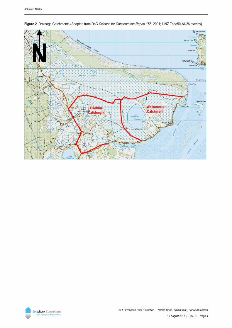
Proposed operations are primarily restricted to the Okohine and Waikaramu drainage catchments, as shown in Figure 2.
Figure 1 Site Location (LINZ Topo50-AU26, 1:50,000)
N
Approximate investigation area
Job Ref: 16325
AEE: Proposed Peat Extraction | Norton Road, Kaimaumau, Far North District
18 August 2017 | Rev. C | Page 4
Figure 2 Drainage Catchments (Adapted from DoC Science for Conservation Report 155, 2001; LINZ Topo50-AU26 overlay)
N
Waikaramu Catchment
Okohine Catchment

Job Ref: 16325
AEE: Proposed Peat Extraction | Norton Road, Kaimaumau, Far North District
18 August 2017 | Rev. C | Page 5
Figure 3 Topographic Site Features
N

Job Ref: 16325
AEE: Proposed Peat Extraction | Norton Road, Kaimaumau, Far North District
18 August 2017 | Rev. C | Page 6
PART A – DESKTOP REVIEW
3 Geology
Reference has been made to GNS Geology of the Kaitaia Area (Geological Map 1, 1996, scale 1:250k) and the GNS webmap
(http://data.gns.cri.nz/geology/), which indicates that the site is underlain by unconsolidated sand, mud and peat of the Tauranga
Group of Holocene age (i.e. <12 ky), and by weakly consolidated dune deposits of the Kariotahi Group of Holocene to
Pleistocene age (i.e. <128 ky). Local geology is shown in Figure 4.
Figure 4 Local Geology (http://data.gns.cri.nz/geology/; LINZ Topo50-AU26 overlay)
Tauranga Group materials are described as being variable in terms of consistency and strength and are found typically along
stream channels and flood plains of creeks, or along localised gully features. They are very thinly to thickly bedded, variously
coloured, angular to well rounded, mixed sized (usually graded, coarse becoming fine upwards) beds of light grey to orange
brown muds, sand and gravel, comprising some rock fragments in places and may include some beds of black, humus rich clay
and fibrous peat. These materials are unconsolidated to very soft and are unweathered.
Kariotahi Group materials are described being moderately consolidated to unconsolidated dune sands and interdune sediments.
Around the Kaimaumau area Kariotahi Group dunes are noted as frequently containing peat swamps in interdune hollows.
Kariotahi Group materials area otherwise similar to those described in the Tauranga Group.
N eQd
eQd Q1a
Q1dM Q1dF
Q1dF eQd
Lithologic Codes
Tauranga Group Q1a - Unconsolidated sand, mud & peat
Kariotahi Group Q1dM - Loose sand (mobile dunes) Q1dF - Loose sand (coastal foredunes) Q1dP - Sand (fixed parabolic dunes) eQd - Poorly cemented coastal foredunes & clay rich sand soils
Q1dP

Job Ref: 16325
AEE: Proposed Peat Extraction | Norton Road, Kaimaumau, Far North District
18 August 2017 | Rev. C | Page 7
With respect to the investigation area, the peat soils targeted for extraction (and their stratigraphic relation to sand ridgelines)
indicates that these soils belong to the Kariotahi as described above. However, with respect the local geology shown in Figure 3,
the area of proposed extraction is mapped as being unconformably overlain by Tauranga Group materials.
Reference to available soil order maps of New Zealand (www.nzsoils.org.nz) indicates that the greater Kaimaumau area is
underlain by both organic and podzol soil types. Organic soils are primarily comprised of decomposed wetland plants (e.g. peat).
Podzol soils include accumulation of aluminium and iron oxides in association with organic matter and are typical of areas of high
rainfall. Both organic and podzol soils may be associated with Acid Sulphate Soils (ASS).
Work previously undertaken by Opus International Consultants Ltd for the Whangarei District Council (ASS Planning Policy Basic
Guide, 2015) has identified significant ASS potential in soils of the both Tauranga Group and Kariotahi Group, particularly where
landform elevations are less than RL20m, peat or coal deposits are present, and low-lying water-logged areas (e.g. wetlands /
back swamps). While the referenced study does not extend to the Kaimaumau area, the geological and environmental settings
are appreciably similar.
The presence of potential Acid Sulphate Soils within the investigation area has not been assessed.
4 Project Background
Resin & Wax Holdings Ltd currently hold an existing Mining License 35156 for the extraction and processing of peat soils from the
Kaimaumau Peatlands, within the area owned by Ngai Takoto iwi. The proposed area of operations includes re-establishment
within the 1987 mining area on the southern / south-western side of Lake Waikaramu, where peat soil deposits average
approximately 2m thickness.
4.1 Available Information
Multiple sources of information have been reviewed / referenced as part of this investigation, including information made available
to Soil & Rock Consultants by Resin & Wax Holdings Ltd. Sources of information reviewed as part of this desktop AEE include:
• Kaimaumau Mine Management Plan Rev. 1 (Resin & Wax Holdings, received June 2016);
• Kaimaumau Info Layouts June 2014 (NCC Consulting Engineers, 2011, Job No. 1480);
• Plan of Coal Mining Licence (Cuttriss Land Surveyors, Drawing No. 18212, Sept. 2001);
• Misc. correspondence re: Sovereign Station Weir Design (NCC Consulting Engineers, Oct. 2011);
• Kaimaumau Topographic Survey, portion of Lot 6 DP 405064 (NCC Consulting Engineers, April 2011, Job No 1480);
• Land Management and Soil Conservation on Sandy Peat Soils (excerpt only, Bob Cathcart, undated);
• Kaimaumau Peat Reserves (Map No. 3 [partial], unreferenced);
• Kaimaumau Peatlands (Map No. 4 Cross-Sections, unreferenced);
• Kauri Resin Extraction and Land Reclamation Project (Cuttriss, McKenzie, Martin & Co, Dec. 1979);
• Kaimaumau Property - Vegetation Types / Vegetation Summary (4Sight Consulting, Feb. 2016);
• Clint Hanger pers. comm (NCC Consulting Engineers, 2016).

Job Ref: 16325
AEE: Proposed Peat Extraction | Norton Road, Kaimaumau, Far North District
18 August 2017 | Rev. C | Page 8
Additional public information sources have included:
• Options for Managing the Kaimaumau Wetland, Northland, New Zealand (Science for Conservation 155, Department of
Conservation, Hicks et al, 2001);
• Climate Database - Kaitaia Aero EWS & Kaitaia EWS (National Hydrometric Database, NIWA, 2016).
Additional technical literature references have included:
• A Review of Hydraulic Conductivity and Compressibility of Peat (Wong et al, 2009);
• Parametrization of Peatland Hydraulic Properties for the Canadian Land Surface Scheme (Letts et al, 2000);
• Hydraulic conductivity in upland blanket peat: measurement and variability (Holden & Burt, 2003);
• Estimation of the Unsaturated Hydraulic Conductivity of Peat Soils: Laboratory versus Field Data (Schwärzel et al, 2006);
• Mining Buried Resin (Kauri Gum) - An Engineering Perspective (Matich et al, 2011)
Synopses of the two most extensive previous assessments are presented in the Section 4.1.1 (Cuttriss et al, 1979) and Section
4.1.2 (DoC, Hicks et el, 2001).
4.1.1 Kauri Resin Extraction and Land Reclamation Project (Cuttriss et al, 1979)
Previous investigation and reporting with respect to a former project concept and environmental assessment was undertaken by
Cuttriss, McKenzie, Martin & Co in 1979. At this time the proposed project entailed a similar commercial enterprise as currently
proposed by Resin & Wax Holdings Ltd over an approximately 2,200ha mining area, with a high priority being restoration of
worked over land (i.e. reinstatement of extraction areas to productive/useful land). It should also however be well noted that the
previous proposal included provision for “restoration” of Lake Waikaramu, and makes reference to proposed drainage of the
Waihauhau and Motutangi swamps (now conservation area and scientific reserve respectively). Further, creation of a new lake to
assist in surface and dewatering control was proposed.
Of relevance to the current proposal by Resin & Wax Holdings Ltd, the previous proposal recommended:
• Intensive in situ drainage of peat via lateral surface drains to achieve optimum moisture content prior to excavation;
• Excavation of peat soils to the underlying sand base (c. sand dune hard pan), with subsequent depth of reclamation being
the “undulating surface of the sandstone strata” (i.e. top of the Aupouri Aquifer);
• Extraction of 6,000m³ to 7,000m³ of peat soil per working day for processing;
• Working over of approximately 55ha to 65ha per annum (sic. “80-100ha per 18 months”);
• Treatment of peat water with “milk of lime” to neutralise typically high acidity, and pond settling to removal peat soil fines.
Of particular importance is was recognised that the proposed extraction area comprised a surface water catchment of
predominantly “internal origin” and that “the proposed drainage systems will eventually control the effects of tidal variation”.
Measurements of surface water indicated a pH of 3.1, indicative of relatively high acidity and considered potentially harmful to
aquatic life, and requiring “heavy application of lime” to achieve soil conditioning to a pH of 4.5-5.5 for pastoral grasses. It should
be well noted that although the previous assessment considered that the establishment of a “functional drainage system together
with soil improvements will establish a much better environment for the improvement of surface water” and that there would be
“no effect to fishing nor fish spawning grounds”, it was recognised that the bulk of drainage would be directed to Otiaia Point

Job Ref: 16325
AEE: Proposed Peat Extraction | Norton Road, Kaimaumau, Far North District
18 August 2017 | Rev. C | Page 9
“where discharge to the sea will be clear of tidal flats” and that no quantitative assessment of surface water or peat drainage
discharge was provided in the reviewed information.
It is concluded that the previous assessment, while undertaken for a significantly more extensive area, is considered insufficient
to current environmental and best practice standards. The previous assessment however has been undertaken prior to creation
of the Motutangi swamp Scientific Reserve in 1984.

Job Ref: 16325
AEE: Proposed Peat Extraction | Norton Road, Kaimaumau, Far North District
18 August 2017 | Rev. C | Page 10
4.1.2 Options for Managing the Kaimaumau Wetland, Northland, New Zealand (Hicks et al, 2001)
Scientific reporting by Hicks, Campbell and Atkinson for the Department of Conservation in 2001 details results of a 1996/1997
scoping study undertaken in relation to identifying potential management responses of the Kaimaumau wetland. The study
relates to perceived drying out of the wetland following a period of low annual rainfall, and is primarily concerned with assessment
of invasive exotic plant species (esp. Sydney golden wattle). Regardless, significant information relating to existing drainage
patterns is presented, including the form and function of existing excavated drainage channels.
Of primary relevance to the desktop assessment presented here, reference to the existing “Salles (Kaurex)” drain and
“Waikaramu” drain indicate that:
• Reactivation of the “Kaurex drain network” is unlikely to pose a threat to conservation land, and that flow from this
network is primarily to the Rangaunu Harbour;
• Drainage of any future mining areas northwards through the Lake Rd ridge (north of investigation area) would be
“inconsistent with maintaining water quality and wetland habitat in the Waihuahua and Otiaia catchments”;
• The former Waikarumu drain culvert beneath Airstrip Road to Lake Waikaramu was removed at the cessation of Kaurex
operations in the 1980’s.
Drainage assessment of the lake catchment indicates that the investigation area is considered effectively dammed from Lake
Waikaramu by Airstrip Road. It is further noted within the report that alteration to Lake Waikaramu, either from direct mining of
gum or peat, or by use as a reservoir for mining operations, would be “detrimental to the Lake’s geological significance and value
as a wildlife habitat”.
Additional reference is made to water quality analyses of peat water undertaken by Kaurex in 1982 (Kauri Deposit Surveys,
unpublished Environmental Impact Report). Although uncited by Soil & Rock Consultants as part of this desktop assessment, the
DoC references indicates that although analyses were not indicative of “abnormal” contaminant levels, both spatial distribution of
samples and selected contaminants for analysis were limited.
4.2 Proposed Operations
The proposed peat soil mining operations is comprised of:
• Spatially discrete excavation of peat across approximately 5ha areas, with up to approximately 20ha per annum of open cast
mining;
• Drainage of operational extraction areas achieved via lateral surface drains at approximately 200m spacing, excavated to
sufficient depth to achieve dewatering across open mining areas to a depth no less than the average depth of targeted peat
deposits (2m bpgl), but up to a maximum excavation depth of 8m bpgl where deeper localised deposits are present;
• Cross-fall connection drains (lattice drains) at 20m to 40m spacing;
• Mechanical separation (e.g. disc-screen) of peat soil from fibrous organics (e.g. logs);
• Atmospheric drying (open air drying pads) of peat soils to achieve approximately 40% moisture content, and industrial
processing for extraction of resins of waxes;
• Re-deposition of processed peat soils within operationally mined extraction areas (cf. historical mined areas);
• Back-filling / blocking of redundant drainage lines where proposed operations have ceased to allow recovery of groundwater.

Job Ref: 16325
AEE: Proposed Peat Extraction | Norton Road, Kaimaumau, Far North District
18 August 2017 | Rev. C | Page 11
Information provided to Soil & Rock Consultants indicates that the proposed extraction is to be undertaken with mobile equipment
comprised of a minimum of one 30T excavator, one disc-screen unit with hopper and conveyer belt for loading, and two tractor
units with tipping trailers. Post-drying processing equipment (Run-Of-Mine [ROM] processing plant) is of an industrial nature and
not relevant to physical extraction and dewatering considerations. Each tractor unit will transport up to approximate 10m³/trip
from the active working area to the drying pads at the ROM, necessitating two tractor units to optimise excavator efficiency.
Prior to processing moisture content in the peat soils requires reduction from c.90% to c.40% and is be achieved via wind-row
drying pads with typically between 3-5 days (weather dependent) of drying to achieve the required moisture content. Drying pads
will initially hold approximately 2,000m³ of peat soils, increasing to up to approximately 8,000m³ of peat soils at peak site
operation.
Following drying and processing (i.e. extraction of resins and waxes) “spent” peat soils will be returned to the extraction site for
remixing with previously screened fibrous organics and subsequent deposition within worked out areas, or such other relocation
as is determined by an approved management plan.
Reinstatement of worked out areas is aimed to allow long-term development by Ngai Takoto, and may involve ecological wet
areas, natural or managed re-vegetation agribusiness and horticulture. At present the proposed area of peat soil extraction has
marginal (if any) viability for commercial land use. Final landform design will be dependent on post-processing material volumes
for re-deposition and available balancing volumes of “top-up” material for capping (e.g. topsoil and/or sand).
4.3 Area of Operations
Extraction of peat soils is proposed between the mapped sand ridgelines (interdune hollows as described in Section 3.0).
Excerpts from provided stratigraphic long-sections of the peat reserves are presented in Figure 5. The spatial distribution of peat
soils identified across the Kaimaumau peatlands is shown in Figure 6.
Figure 5 Peat Reserve Long-sections (from Map No. 4 Kaimaumau Peatland; Section locations Figure 5)
Sect. III
Sect. II
Sect. I

Job Ref: 16325
AEE: Proposed Peat Extraction | Norton Road, Kaimaumau, Far North District
18 August 2017 | Rev. C | Page 12
Figure 6 Kaimaumau Peat Deposits (Adapted from Map No. 3 Kaimaumau Peat Reserves; LINZ Topo50-AU26 & Rural aerial phot survey overlays)
4.4 Potential For Adverse Effects
Appreciable potential for adverse environmental effects resulting from the proposed operations have previously identified by both
the Northland Regional Council (NRC) and the Department of Conservation (DoC). Of primary importance for identification (and
mitigation) of areas susceptible to potential adverse effects are:
• Waihuahua Swamp Scientific Reserve (upstream);
• Lake Waikaramu (lateral);
• Waiparera Stream / Rangaunu Harbour (downstream).
N Sect. III Sect. II Sect. I (Fig. 5)

Job Ref: 16325
AEE: Proposed Peat Extraction | Norton Road, Kaimaumau, Far North District
18 August 2017 | Rev. C | Page 13
Both Waihuahua Swamp and Lake Waikaramu have been identified as potential receiving environments for discharge of drain
dewatering. Previous operations by Kaurex (c. 1980s) included excavation of an east-to-west surface drain (Waikaramu drain)
from Lake Waikaramu to the north-to-south flowing Salles / Kaurex drain, which was used for water supply as part of the 1980’s
excavation operation (DoC, 2001). This existing surface water drainage represents potential for enhanced drainage from the
ephemeral Lake Waikaramu, particularly where the radius of influence of groundwater lowering (drawdown) may extend to within
the Waikaramu surface water catchment (cf. Figure 2).
Consideration of potential adverse effects within the Okohine catchment are primarily limited to effects resulting from groundwater
drawdown, such as flora distress or watercourse drainage, however discharge of groundwater from proposed surface drains
presents potential for additional adverse ecological effects where sufficient difference exist between the geochemical properties of
discharging and receiving waters.
Of un-assessed potential is the possible presence of Acid Sulphate Soils. Should sulphides be present in the soils through the
proposed extraction area the potential for generation resulting from disturbance and oxidation of sulphide minerals need be
assessed and appropriate management of potential runoff/discharge put in place.
5 Territorial Authority Regulations
5.1 Northland Regional Council
Reference has been made to the Regional Water and Soil Plan for Northland (RWSP, Northland Regional Council; Updated
2016) to determine relevant district rules relating to the proposed dewatering of the Kaimaumau Peatlands. Controlled Activity
(CA) criteria are addressed under Section 25.2 and state that:
“Ground dewatering of existing quarries and mine sites and ground dewatering by way of existing drainage sumps
which do not draw water from at risk aquifers are controlled activities.
Matters Subject to Control:
(1) Location and design of dewatering wells;
(2) Extent of dewatering;
(3) Mitigation measures.
Diversion of water from an indigenous wetland is considered a Non-Complying Activity under the RWSP. Consequently,
mitigation via design (e.g. flow barrier or drainage buffer) will be required to satisfy Controlled Activity criteria, as per (3) above.
No effects on at risk aquifers or existing lawful groundwater users are anticipated, given that the proposed groundwater diversion
is from a perched water within the peat soils targeted for extraction.

Job Ref: 16325
AEE: Proposed Peat Extraction | Norton Road, Kaimaumau, Far North District
18 August 2017 | Rev. C | Page 14
5.2 Far North District Council
Relevant rules associated with the proposed peat extraction with respect to the District Plan (Far North District Council) are listed
under Section 8.8 (Minerals Zone) which specifies expected environmental outcomes that:
8.8.2.1 A rural area in which the effects of mineral extraction are acceptable in the context of sustainable management of
natural and physical resources.
8.8.2.2 Potential reverse sensitivity effects related to lawfully established mineral extraction operations are managed.
Further reference to relevant policies specifies:
8.8.4.1 That the Minerals zone generally apply to those areas of the District where large scale mining or quarrying activities are
conducted, or will be conducted.
8.8.4.2 That the establishment of new Minerals Zones or extension of the Minerals Zone be through the Plan Change process,
allowing for a thorough assessment of the likely effects on the environment and evaluation of methods for avoiding,
remedying or mitigating such effects. A Development Plan will be required as part of any Plan Change (refer Rule
8.8.5.3.3).
8.8.4.3 When considering a Plan Change, that sufficient land be included in the Minerals Zone to accommodate the activities
shown on the Development Plan, to mitigate any adverse effects of mining and quarrying on the environment and to
reduce the likelihood of reverse sensitivity effects.
8.8.4.4 That performance standards be provided to avoid, remedy or mitigate adverse environmental effects on adjacent zones.
8.8.4.5 That Development Plans be required to address, with amendments over time as appropriate, rehabilitation of areas no
longer capable of being actively mined or quarried, and to provide justification for any areas where such rehabilitation is
impracticable or unnecessary.
8.8.4.6 That conflicts between mineral extraction and other activities be avoided by ensuring that incompatible activities do not
establish within, or near, the Minerals Zone.
8.8.4.7 That applications for discretionary consent involving mining and quarrying activities be accompanied by a Development
Plan prepared in accordance with Rule 8.8.5.3.3.
8.8.4.8 That mining tailings that contain toxic or bio-accumulative chemicals are contained in such a way that adverse effects
on the environment are avoided.
In respect to the policies as described above, as with the NWSP appropriate management of mine dewatering and mitigation of
potential adverse effects is required. It should be noted that Policy 8.8.4.8 specifically requires mitigation of potential toxins within
dewatering discharge.
Job Ref: 16325
AEE: Proposed Peat Extraction | Norton Road, Kaimaumau, Far North District
18 August 2017 | Rev. C | Page 15
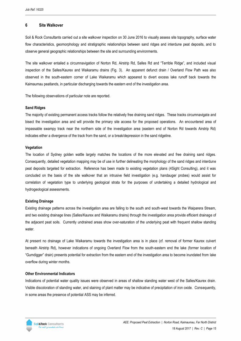
6 Site Walkover
Soil & Rock Consultants carried out a site walkover inspection on 30 June 2016 to visually assess site topography, surface water
flow characteristics, geomorphology and stratigraphic relationships between sand ridges and interdune peat deposits, and to
observe general geographic relationships between the site and surrounding environments.
The site walkover entailed a circumnavigation of Norton Rd, Airstrip Rd, Salles Rd and “Terrible Ridge”, and included visual
inspection of the Salles/Kaurex and Waikaramu drains (Fig. 3). An apparent defunct drain / Overland Flow Path was also
observed in the south-eastern corner of Lake Waikaramu which appeared to divert excess lake runoff back towards the
Kaimaumau peatlands, in particular discharging towards the eastern end of the investigation area.
The following observations of particular note are reported.
Sand Ridges
The majority of existing permanent access tracks follow the relatively free draining sand ridges. These tracks circumnavigate and
bisect the investigation area and will provide the primary site access for the proposed operations. An encountered area of
impassable swampy track near the northern side of the investigation area (eastern end of Norton Rd towards Airstrip Rd)
indicates either a divergence of the track from the sand, or a break/depression in the sand ridgeline.
Vegetation
The location of Sydney golden wattle largely matches the locations of the more elevated and free draining sand ridges.
Consequently, detailed vegetation mapping may be of use in further delineating the morphology of the sand ridges and interdune
peat deposits targeted for extraction. Reference has been made to existing vegetation plans (4Sight Consulting), and it was
concluded on the basis of the site walkover that an intrusive field investigation (e.g. handauger probes) would assist for
correlation of vegetation type to underlying geological strata for the purposes of undertaking a detailed hydrological and
hydrogeological assessments.
Existing Drainage
Existing drainage patterns across the investigation area are falling to the south and south-west towards the Waiparera Stream,
and two existing drainage lines (Salles/Kaurex and Waikaramu drains) through the investigation area provide efficient drainage of
the adjacent peat soils. Currently undrained areas show over-saturation of the underlying peat with frequent shallow standing
water.
At present no drainage of Lake Waikaramu towards the investigation area is in place (cf. removal of former Kaurex culvert
beneath Airstrip Rd), however indications of ongoing Overland Flow from the south-eastern end the lake (former location of
“Gumdigger” drain) presents potential for extraction from the eastern end of the investigation area to become inundated from lake
overflow during winter months.
Other Environmental Indicators
Indications of potential water quality issues were observed in areas of shallow standing water west of the Salles/Kaurex drain.
Visible discoloration of standing water, and staining of plant matter may be indicative of precipitation of iron oxide. Consequently,
in some areas the presence of potential ASS may be inferred.

Job Ref: 16325
AEE: Proposed Peat Extraction | Norton Road, Kaimaumau, Far North District
18 August 2017 | Rev. C | Page 16
Plate 1 Salles/Kaurex Drain Plate 2 PASS Indicators
Plate 3 Potential sand ridge break (NE corner of site) Plate 4 Typical Peatland Terrain
7 Hydrology
A surface water (i.e. hydrology) assessment has been carried out to assess existing capacity of the local drainage network
flowing to the Waiparera Stream (Rangaunu Harbour) to the south-west of the investigation area. Due to limited availability of
topographic / contour information for the catchment, the catchment runoff calculations are maximum estimates only, based on an
assumed catchment geometry in respect to know spot heights.
Reference has been made to Figure 3 of the document ‘Options for Managing The Kaimaumau Wetland, Northland, New
Zealand’ (DoC, 2001), for catchment delineation of the Okohine catchment. The catchment extends to the north-west of the
investigation area, above the origin of the Okohine Stream approximately in line with the Norton Road. The central catchment

Job Ref: 16325
AEE: Proposed Peat Extraction | Norton Road, Kaimaumau, Far North District
18 August 2017 | Rev. C | Page 17
drainage path is the Okohine Stream, with the investigation area comprising the majority of catchment to the east of the Okohine
stream (up to approximately 1/3 of catchment area).
A total catchment of approximately 1,200 hectares has been delineated to assess the total current runoff contributing to the
existing drains and streams, and is equivalent to the predicted total discharge at the Waiparera Stream. Land use within the
identified catchment is predominantly rural farm land west of the Ohokine Stream, wetland / peat swamp to the east. Reference
to the available geological literature the catchment is underlain by sands, mud and peat which are best regarded as Hydrological
Soil Group B (Alluvial sediments) with respect to watershed runoff modelling (TR-55; Urban hydrology for small watersheds, US
Department of Agriculture, 1986).
Catchment runoff assessments have been carried out on the basis of the modified Rational method as per TR-55 in order to
assess design storm peak runoff rates for the entire catchment. Rainfall data has been adopted from NIWA National Hydrometric
Database (Climate database - Kaitaia Aero EWS & Kaitaia EWS) for 2-year, 10-year and 100-year Annual Recurrence Interval
(ARI), 24 hour duration rainfall events. Curve Numbers (CN values) have been applied form TR-55 and from Table 3.3 of
Auckland Council publication TP108 based on a Group B Soil (Alluvial deposits).
A breakdown of the model coverage areas, detailed runoff calculations and Peak flow values are shown in Worksheet 1 and
Worksheet 2 (Appendix A). The varying catchment characteristics have been modelled by applying specific characteristics (slope,
size, length, CN factor etc.). Selected input parameters and calculated peak flow rates for the entire catchment for 2-, 10- and
100-year design storm events are summarised in Table 1 below:
Table 1: Design Storm Intensities & Modelled Runoff (Okohine Catchment)
Design Storm Event Storm 1 Storm 2 Storm 3
ARI - Annual Recurrence Interval (years) 2 10 100
P24 - 24 hour Rainfall Depth (mm) 102.5 152 248.5
qp - Peak Flow Rate (m³/s) 17.2 31.0 65.6
Q24 - 24 hour Runoff Depth (mm) 37.28 70.94 147.79
Monthly total rainfall data has been adopted from NIWA for the year period of 2006 to June 2016 at Waiharara Station (the
nearest rain station close to Kaimaumau). The recorded monthly rainfall varies from 7.7mm (February 2013) to 280.3mm
(January 2011). The year of 2011 has the highest total annual rainfall with both January and December monthly rainfall exceeded
200mm. Based on the monthly average rainfall data for the last 9 years (2006 – 2015), the wettest month is July and the driest
month is January.
Monthly evaporation data has been adopted from NIWA for the year period of 2006 to June 2016 at Station Kaitaia Aero Ews.
The adopted data has been recorded as monthly total evaporation in mm using the Total Penman Open Water Evaporation
method. The recorded monthly evaporation rate ranged from 28.6mm (August 2007) to 150.6mm (January 2013).

Job Ref: 16325
AEE: Proposed Peat Extraction | Norton Road, Kaimaumau, Far North District
18 August 2017 | Rev. C | Page 18
7.1 Hydrology Discussion
On the basis of the appended surface water runoff modelling it is concluded that the existing drainage network is theoretically
capable of accommodating extremely large runoff flows during design storm events. It is noted from the previous work undertaken
by the Department of Conservation (DoC, 2001) that previous discharge from Lake Waikaramu via the Waikaramu drain had
ceased.
However as noted in Section 5, the presence of Overland Flow Paths on the areas of the former drain and culvert lines may
indicate a more significant surface water connectivity between the Okohine and Waikaramu catchments, which would effectively
increase the baseline flow through the former Kaurex drains (i.e., “Kaurex”/Salles & Waikaramu) and consequently to the
discharge point at the Waiparera Stream.
It would be considered beneficial to undertake further surface water modelling for the Kaurex drain network following generation
of a full site survey of the proposed operations area and western side of lake Waikaramu.
With reference to previous literature it is concluded that reinstatement of any drainage from Lake Waikaramu (e.g. Waikaramu
drain culvert beneath Airstrip Rd) should be avoided. Discharge of proposed dewatering drains to the lake is not considered
practical.
8 Desktop Hydrogeological Assessment
Preliminary quantitative assessments of groundwater dewatering have been undertaken for excavation of lateral drains though
proposed areas of peat extraction, and have included both a first-principles approach (Theis equation drawdown) and basic
numerical computer model using Visual MODLFOW. Results of Theis equation Distance-Drawdown calculations are presented in
Table 2 and Table 3, and have been performed using the following parameters:
• Transmissivity (T) = 15 m² / day
• Storativity (S) = 0.66
• Pumping rate (Q) = 1 l/s

Job Ref: 16325
AEE: Proposed Peat Extraction | Norton Road, Kaimaumau, Far North District
18 August 2017 | Rev. C | Page 19
Table 2: Theis Equation for Time-Drawdown (Single Drain)
Radius (m) 10 75 200
Time (Days) Drawdown (m)
1 0.085 - -
10 0.796 0.000 -
20 1.090 0.005 -
30 1.267 0.021 0.000
60 1.577 0.095 0.000
90 1.760 0.175 0.001
120 1.890 0.248 0.003
150 1.992 0.313 0.007
180 2.075 0.370 0.012
225 2.177 0.445 0.024
270 2.260 0.510 0.038
315 2.330 0.567 0.054
365 2.397 0.623 0.072
Table 3: Theis Equation for Distance-Drawdown (Single Drain)
Time (Days) 30 180 365
Radius (m) Drawdown (m)
1 3.362 4.183 4.507
5 1.890 2.708 3.032
10 1.267 2.075 2.397
20 0.680 1.448 1.766
25 0.510 1.249 1.565
50 0.116 0.664 0.955
100 0.003 0.204 0.414
150 0.000 0.055 0.179
200 0.000 0.012 0.072
250 - 0.002 0.026
300 - 0.000 0.009
350 - 0.000 0.003
400 - 0.000 0.001
Following “first-principles” Theis calculations, anticipated drawdown and radius of influence calculations have been compared to
preliminary finite element modelling (Steady-State) using Visual MODLFOW (v. 2012.1, Schlumberger Water Services), with
drawdown simulated by multiple drain packages (DRN boundary condition).
Finite element modelling has been based on 1,200m wide by 500m long, two layered, 10m by 10m grid. The grid has been
refined to 3m by 10m around the locations of five (5) evenly spaced drains, each drain being of 500m length (top of grid to bottom

Job Ref: 16325
AEE: Proposed Peat Extraction | Norton Road, Kaimaumau, Far North District
18 August 2017 | Rev. C | Page 20
of grid), at 200m spacing between drains, and 3m depth. Drains have been incrementally activated over several model runs to
assess both individual and cumulative effects.
Perimeter boundary conditions have been modelled on the basis of constant head boundaries (CHB), as no loss from the
adjacent sand ridges is expected due to the impermeable hard pan, nor from Lake Waikaramu due to the Airstrip Rd drainage
divide. Constant head values have been derived from available survey measurements of water level elevations (NCC Consulting
Engineers), and groundwater gradients extrapolated across the extent of the model grid.
In the absence of site specific values of hydraulic conductivity, storage or porosity, the following values have been discretionally
adopted from the references of technical literature (Section 4.1), and has included reference to hydraulic characteristics reported
for the Aupouri aquifer (Groundwaters of New Zealand, NZHS 2001):
• Hydraulic Conductivity (Kx, Ky & Kz) = 6.3 x 10⁻⁸ m/s
• Specific Storage (Ss) = 0.66 (L-1)
• Specific Yield (Sy) = 0.66 (dimensionless)
• Effective Porosity (ne) = 83%
• Total Porosity (nΣ) = 83%
Visual presentation of drain dewatering effects for a homogenous isotropic peat deposit are presented in Figure 7 for a single
drain, three (3) parallel drains, and five (5) parallel drains scenarios modelled in Visual MODLFOW.
Job Ref: 16325
AEE: Proposed Peat Extraction | Norton Road, Kaimaumau, Far North District
18 August 2017 | Rev. C | Page 21
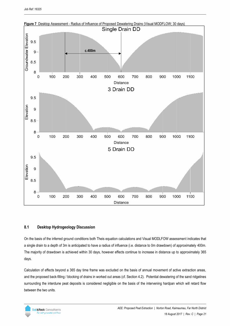
Figure 7 Desktop Assessment - Radius of Influence of Proposed Dewatering Drains (Visual MODFLOW; 30 days)
8.1 Desktop Hydrogeology Discussion
On the basis of the inferred ground conditions both Theis equation calculations and Visual MODLFOW assessment indicates that
a single drain to a depth of 3m is anticipated to have a radius of influence (i.e. distance to 0m drawdown) of approximately 400m.
The majority of drawdown is achieved within 30 days, however effects continue to increase in distance up to approximately 365
days.
Calculation of effects beyond a 365 day time frame was excluded on the basis of annual movement of active extraction areas,
and the proposed back-filling / blocking of drains in worked out areas (cf. Section 4.2). Potential dewatering of the sand ridgelines
surrounding the interdune peat deposits is considered negligible on the basis of the intervening hardpan which will retard flow
between the two units.
c.400m
Job Ref: 16325
AEE: Proposed Peat Extraction | Norton Road, Kaimaumau, Far North District
18 August 2017 | Rev. C | Page 22
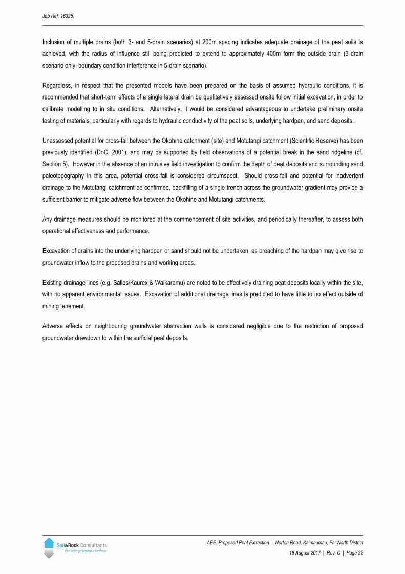
Inclusion of multiple drains (both 3- and 5-drain scenarios) at 200m spacing indicates adequate drainage of the peat soils is
achieved, with the radius of influence still being predicted to extend to approximately 400m form the outside drain (3-drain
scenario only; boundary condition interference in 5-drain scenario).
Regardless, in respect that the presented models have been prepared on the basis of assumed hydraulic conditions, it is
recommended that short-term effects of a single lateral drain be qualitatively assessed onsite follow initial excavation, in order to
calibrate modelling to in situ conditions. Alternatively, it would be considered advantageous to undertake preliminary onsite
testing of materials, particularly with regards to hydraulic conductivity of the peat soils, underlying hardpan, and sand deposits.
Unassessed potential for cross-fall between the Okohine catchment (site) and Motutangi catchment (Scientific Reserve) has been
previously identified (DoC, 2001), and may be supported by field observations of a potential break in the sand ridgeline (cf.
Section 5). However in the absence of an intrusive field investigation to confirm the depth of peat deposits and surrounding sand
paleotopography in this area, potential cross-fall is considered circumspect. Should cross-fall and potential for inadvertent
drainage to the Motutangi catchment be confirmed, backfilling of a single trench across the groundwater gradient may provide a
sufficient barrier to mitigate adverse flow between the Okohine and Motutangi catchments.
Any drainage measures should be monitored at the commencement of site activities, and periodically thereafter, to assess both
operational effectiveness and performance.
Excavation of drains into the underlying hardpan or sand should not be undertaken, as breaching of the hardpan may give rise to
groundwater inflow to the proposed drains and working areas.
Existing drainage lines (e.g. Salles/Kaurex & Waikaramu) are noted to be effectively draining peat deposits locally within the site,
with no apparent environmental issues. Excavation of additional drainage lines is predicted to have little to no effect outside of
mining tenement.
Adverse effects on neighbouring groundwater abstraction wells is considered negligible due to the restriction of proposed
groundwater drawdown to within the surficial peat deposits.
Job Ref: 16325
AEE: Proposed Peat Extraction | Norton Road, Kaimaumau, Far North District
18 August 2017 | Rev. C | Page 23
PART B – DETAILED ASSESSMENT
9 Field Investigation
Following completion of the desktop assessment, and after discussion with the FNDC/NRC, further investigation has been
undertaken by Soil & Rock Consultants from May to July 2017. The primary objectives of the Detailed Investigation have been to
provide clarification with respect to the following:
1. Site Specific Hydraulic Characterisation:
1.1. Determination of site specific groundwater characteristics;
1.2. Calibration of existing groundwater drawdown models for proposed peat dewatering;
1.3. Delineation of subsurface stratigraphy with respect to potential groundwater connectivity between the Okohine and
Motutangi Catchments;
2. Environmental Screening & Baseline Measurements:
2.1. Field screening for Potential Acid Sulphate Soils (PASS), and identification of appropriate mitigation where required;
2.2. Baseline Environmental measurements within the existing drainage network through the site, including outlet
structures to the Waiparera Stream.
To this end, Soil & Rock Consultants have undertaken an intrusive fieldwork investigation in late-May 2017, which has included
both in-situ characterisation and laboratory-controlled testing.
10 Catchment Connectivity
Groundwater beneath the site is differentiated between two flow regimes. Regionally, groundwater flow is within the Aupouri
aquifer, and considered a confined regime at depth beneath the site, due to the presence of the over lying hard pan which
separates flow regional flow from the interdune peat deposits. Shallow (i.e. unconfined) groundwater is present within the
interdune peat deposits, and represents the groundwater table which extends beneath the site and the Motutangi swamp and
wetlands.
The potential for groundwater connection within the interdune peat aquifers beneath the Okohine and Motutangi surface water
catchments has been identified during the desktop investigation. Specifically, the identified area of potential connectivity is
located in the north-eastern corner of (Reserve Area 4), as shown in Figure 8. Intrusive investigation by means of a hand auger
transect along the eastern end of Beacon Rd was carried out in order to assess the depth to the top of the hardpan overlying the
Aupouri Aquifer.
Field mapping undertaken during in May 2017 has confirmed the presence of a continuous sand ridge “high ground” extending
around Reserve Areas 3 & 4 (i.e. Okohine Catchment), with the exception of a minor area at the eastern-most end of Beacon.
This area has been broadly delineated as extending up to 200m (NW-SE) across the north-eastern corner of Reserve Area 4,
effectively ending at a four-way confluence between the Okohine, Motutangi, Waihuahua and Waikaramu Catchments.
In order to assess potential subsurface connectivity (cf. peat dewatering), an auger probe transect line was extended along the
eastern-most 250m of Beacon Rd, ending at the junction with Airstrip Rd, as shown in Figure 8. It was found that although this
section of track is effectively impassable in wet weather due to the soft peat ground, the depth of peat “connecting” the surface
Job Ref: 16325
AEE: Proposed Peat Extraction | Norton Road, Kaimaumau, Far North District
18 August 2017 | Rev. C | Page 24
water catchments at a subsurface level varies between 0.4m, and 0.6m, and is immediately underlain by the Aupouri Aquifer hard
pan.
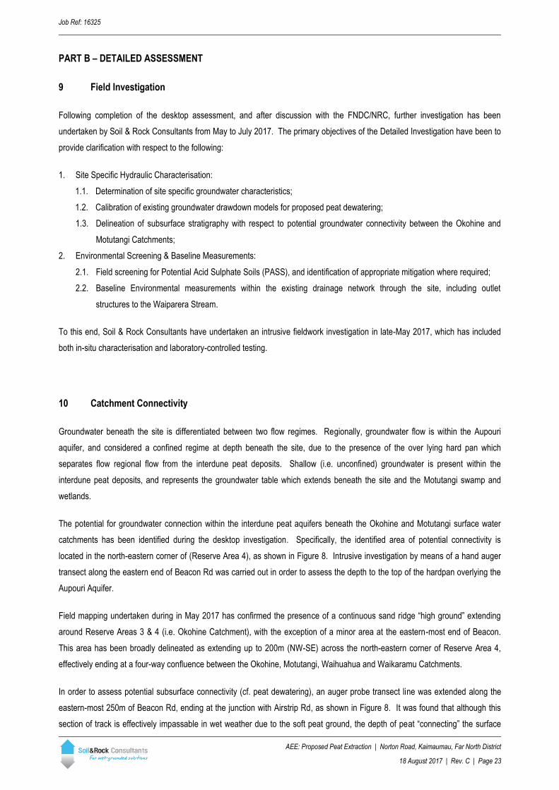
Figure 8 Catchment Connectivity
10.1 Discussion Catchment Connectivity
Sand ridge features separating the proposed extraction areas from the neighbouring Motutangi Swamp wetlands have been
shown to dip below ground level in the north-eastern corner of the site, across an area of no more than 200m perpendicular, and
no more than 200m parallel, to the direction of potential groundwater flow (as shown Figure 8).
The depth of potential groundwater connection between the site and the Motutangi wetlands is on average 0.5m. Consequently,
the potential adverse effects offsite, arising from dewatering of the proposed extraction areas, is considered sufficiently minor that
mitigation via drainage design or low permeability wall (Section 12.1) is readily achievable. Mitigation measures (where required)
are anticipated to be required to operate primarily during winter months, as seasonal variations in groundwater depth are
understood to drying out of the shallow peat in the north-east corner of the site during summer.
N
Reserve Area 5
Beacon Rd
Airstrip
Rd
Reserve Area 4
Reserve Area 3
Okohine Catchment
Motutangi Catchment
Waihuahua Catchment
Waikaramu Catchment
Probe locations
Assessment Area - approx. direction of flow
(subsurface catchment connectivity)
Job Ref: 16325
AEE: Proposed Peat Extraction | Norton Road, Kaimaumau, Far North District
18 August 2017 | Rev. C | Page 25
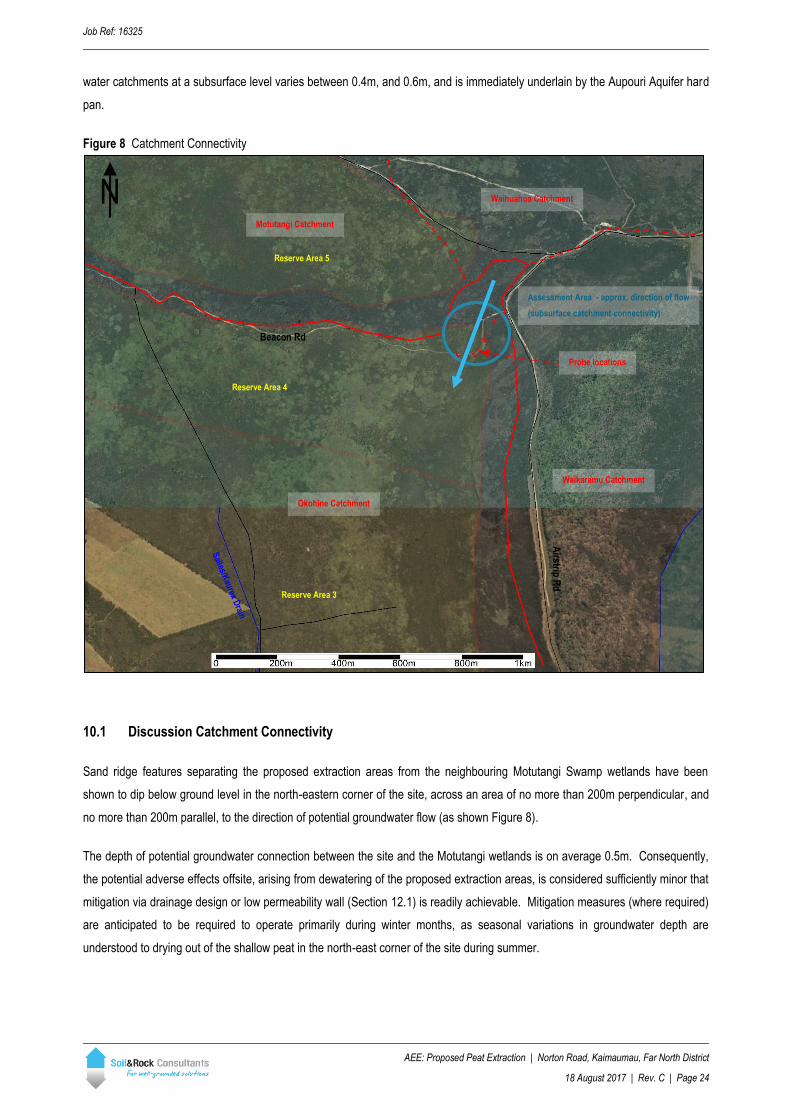
11 Hydraulic Characterisation
For the purposes of providing quantitative hydraulic conductivity (K) values, onsite slug testing (rising head) was performed in
piezometers PZ01 (AH05), PZ02 and PZ04, and laboratory controlled hydraulic conductivity testing carried out on push-tube
samples recovered from adjacent to piezometers PZ01 and PZ04. Further laboratory testing was carried out on two (2) bulk
samples of “spent” (i.e. processed) peat material recovered from the pilot processing plant currently operating in Awanui, north of
Kaitaia. Testing of the post-processing material has been carried out in order to quantify potential changes in hydraulic
conductivity which may arise from the material processing. A summary of hydraulic conductivity test locations is presented in
Table 4, and shown in Figure 9.
Table 4: Hydraulic Conductivity Location Summary
Test/Sample ID Location (NZTM)
Peat Material Type Test Type Easting Northing
PZ01 1619564.7 6136794.2 In situ
Intact push-tube Triaxial Flow Cell
PZ02 1619751.5 6136423.1 In situ
PZ04 1619903.3 6135727.1 In situ
Intact push-tube Triaxial Flow Cell
SP01 NA (1) NA (1) Recompacted post-processing Triaxial Flow Cell
SP02 NA (1) NA (1) Recompacted post-processing Triaxial Flow Cell
Table Notes: NA – Not Applicable (mixed sample from processing plant “waste” stream)
Figure 9 Hydraulic Conductivity Test Locations
N
PZ04
PZ02 PZ01
PZ01 PZ02 PZ04
Facing N from c. Waikaramu Drain
Facing SW from c. Beacon Rd
Beacon Rd
Job Ref: 16325
AEE: Proposed Peat Extraction | Norton Road, Kaimaumau, Far North District
18 August 2017 | Rev. C | Page 26
11.1 Hydraulic Conductivity
11.1.1 Slug Testing
Slug testing is an aquifer testing method where a volume of water is quickly added (falling head) or withdrawn (rising head) from a
groundwater well/piezometer, with subsequent monitoring of changes in hydraulic head (i.e. piezometer water level) over time
until the well/piezometer has returned to its pre-test groundwater elevation.
Test recovery data has been recorded using Solinst groundwater level-loggers, installed as part of a short-term groundwater
monitoring program, and analysis of observation (i.e. recovery) data has been completed using AquiferTest Pro (v.2015.1;
Schlumberger Water Services).
Hydraulic conductivities (K) have been derived using the range of solution methods listed below:
• Bouwer-Rice (1976);
• Hvorslev (1951);
• Cooper-Bredehoeft-Papadopulos (1967);
• Dagan (1978).
It should be noted that the Dagan (1978) method has been applied to testing of PZ01 only due to the limitation of screen-
length:diameter ratio being L:D>50. Similarly, the Cooper-Bredehoeft-Papadopulos (1967) method has been applied to testing of
PZ04 only due to a perceived potential for strata in this testing area to be in a locally confined (or semi-confined) groundwater
regime.
The potential for locally confined conditions in part has arisen from return of plausible results from Cooper-Bredehoeft-
Papadopulos analyses. In our experience, mis-application of this method (i.e. solution method sensitivity check of unconfined
conditions) was noted as yielding results several orders of magnitude difference to any credible range (i.e. outstandingly
erroneous results). Notwithstanding, the aforementioned method has been retained in reporting for the purpose of clarifying
groundwater flow assessment with respect to potential confined (or semi-confined) groundwater flow regimes, and is discussed
further in following sections.
Calculated hydraulic conductivity values are summarised in Table 5. AquiferTest Pro analyses are attached in Appendix A.
11.1.2 Laboratory Testing
In order to the magnitude of change in hydraulic conductivity arising from the processing of the peat materials, and associated
potential for impact on the surrounding natural environment, characterisation of materials recovered from the pilot processing
plant in Awanui have been re-compacted in a triaxial flow cell and tested by Babbage Geotechnical Laboratories.
Laboratory testing has been carried out on two (2) samples from the Awanui plant, in addition to two (2) push-tube samples of
natural material collected onsite.
Reported values indicate negligible difference in hydraulic characteristics arising from the processing of the peat materials.

Job Ref: 16325
AEE: Proposed Peat Extraction | Norton Road, Kaimaumau, Far North District
18 August 2017 | Rev. C | Page 27
Reported hydraulic conductivity values are included in Table 5. Laboratory test results are attached in Appendix A.
11.1.3 Summary of Hydraulic Conductivity
Table 5: Hydraulic Conductivity Testing Summary
ID
In Situ Slug-Testing Triaxial
Flow Cell
Statistical Summary
Bouwer- Rice
Hvorslev CBP (1) Dagan Average Minimum Maximum δ
Hydraulic Conductivity (m/s)
PZ01 1.00 x 10⁻⁸ 1.43 x 10⁻⁸ 1.09 x 10⁻⁸ 5.70 x 10⁻⁹
2.97 x 10⁻⁷ 5.70 x 10⁻⁹ 2.20 x 10⁻⁶ 6.78 x 10⁻⁷ PZ02 1.58 x 10⁻⁸ 2.27 x 10⁻⁸
PZ04 2.34 x 10⁻⁷ 3.40 x 10⁻⁷ 1.19 x 10⁻⁷ 2.20 x 10⁻⁶
SP01 NA 6.80 x 10⁻⁸ 8.40 x 10⁻⁸
SP02 NA 1.00 x 10⁻⁷
Table Notes: (1) Cooper-Bredehoeft-Papadopulos solution method
11.2 Additional Parameters
Laboratory assessment of hydraulic conductivity reports values of initial/final water content, bulk density and dry density, which
have been used to estimate values of Specific Yield (Sy) on the basis that:
With reference to the appended laboratory test results, estimates of Sy have been determined as presented in Table 5.
With respect to analyses methods in Section 11.1.1, the Cooper-Bredehoeft-Papadopulos solution method has been applied to
PZ04 testing data. Given that this method also provides estimates of transmissivity and storage coefficient (a.k.a. storativity), the
reported values can be reduced, given that in a confined groundwater condition:
Estimated Ss for in situ testing at PZ04, as derived on the basis of the Cooper-Bredehoeft-Papadopulos solution method are
included in Table 6.
𝑆𝑦 =𝑉𝑤𝑑
𝑉𝑡
Where: Sy = Specific Yield
Vwd = Volume of water drained
Vt = total volume of material
Where: S = Storativity (Storage Coefficient)
Ss = Specific Storage
b = aquifer thickness
𝑆 = 𝑆𝑠×𝑏
Job Ref: 16325
AEE: Proposed Peat Extraction | Norton Road, Kaimaumau, Far North District
18 August 2017 | Rev. C | Page 28
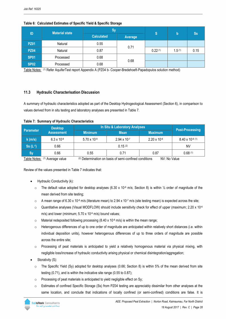
Table 6: Calculated Estimates of Specific Yield & Specific Storage
ID Material state Sy
S b Ss Calculated Average
PZ01 Natural 0.55 0.71
PZ04 Natural 0.87 0.22 (1) 1.5 (1) 0.15
SP01 Processed 0.68 0.68
SP02 Processed 0.68
Table Notes: (1) Refer AquiferTest report Appendix A (PZ04 b- Cooper-Bredehoeft-Papadopulos solution method)
11.3 Hydraulic Characterisation Discussion
A summary of hydraulic characteristics adopted as part of the Desktop Hydrogeological Assessment (Section 6), in comparison to
values derived from in situ testing and laboratory analyses are presented in Table 7.
Table 7: Summary of Hydraulic Characteristics
Parameter Desktop
Assessment
In Situ & Laboratory Analyses Post-Processing
Minimum Mean Maximum
k (m/s) 6.3 x 10⁻⁸ 5.70 x 10⁻⁹ 2.94 x 10⁻⁷ 2.20 x 10⁻⁶ 8.40 x 10⁻⁸ (1)
Ss (L-1) 0.66 0.15 (2) NV
Sy 0.66 0.55 0.71 0.87 0.68 (1)
Table Notes: (1) Average value (2) Determination on basis of semi-confined conditions NV: No Value
Review of the values presented in Table 7 indicates that:
• Hydraulic Conductivity (k):
o The default value adopted for desktop analyses (6.30 x 10⁻⁸ m/s; Section 8) is within ½ order of magnitude of the
mean derived from site testing;
o A mean range of 6.30 x 10⁻⁸ m/s (literature mean) to 2.94 x 10⁻⁷ m/s (site testing mean) is expected across the site;
o Quantitative analyses (Visual MODFLOW) should include sensitivity check for effect of upper (maximum; 2.20 x 10⁻⁶
m/s) and lower (minimum; 5.70 x 10⁻⁹ m/s) bound values;
o Material redeposited following processing (8.40 x 10⁻⁸ m/s) is within the mean range;
o Heterogenous differences of up to one order of magnitude are anticipated within relatively short distances (i.e. within
individual deposition units), however heterogenous differences of up to three orders of magnitude are possible
across the entire site;
o Processing of peat materials is anticipated to yield a relatively homogenous material via physical mixing, with
negligible loss/increase of hydraulic conductivity arising physical or chemical disintegration/aggregation;
• Storativity (S):
o The Specific Yield (Sy) adopted for desktop analyses (0.66; Section 8) is within 5% of the mean derived from site
testing (0.71), and is within the indicative site range (0.55 to 0.87);
o Processing of peat materials is anticipated to yield negligible effect on Sy;
o Estimates of confined Specific Storage (Ss) from PZ04 testing are appreciably dissimilar from other analyses at the
same location, and conclude that indications of locally confined (or semi-confined) conditions are false. It is
Job Ref: 16325
AEE: Proposed Peat Extraction | Norton Road, Kaimaumau, Far North District
18 August 2017 | Rev. C | Page 29
considered likely that such indicators may be related to local confinement arising from track formation and historic
ground disturbance (e.g. anthropogenic).
12 Detailed Hydrogeology
Based on in situ & laboratory testing for determination of site specific ranges of hydraulic characteristics (Section 11), preliminary
assessments of groundwater dewatering (Section 8) have been revised to provide a working design for commencement of
dewatering. Calibration of design (e.g. drainage spacing) is still required, and should be undertaken based on observation of
dewatering rates and drawdown extents at the commencement of operations
Dewatering effects (radius of influence) have been modelling in Visual MODFLOW, using revision of original desktop modelling
presented in Section 8, and has included a sensitivity of upper and lower bound hydraulic conductivities (cf. Section 11.3).
Distance-Drawdown relationships extracted from Visual MODLFOW output are presented in Table 8 and Figure 10.

Job Ref: 16325
AEE: Proposed Peat Extraction | Norton Road, Kaimaumau, Far North District
18 August 2017 | Rev. C | Page 30
Table 8: Visual MODFLOW - Distance-Drawdown Sensitivity Check
Scenario Single Drain Parallel Drain
k = 5.70 x 10⁻⁹ m/s k = 2.94 x 10⁻⁷ m/s k = 2.20 x 10⁻⁶ m/s k = 2.94 x 10⁻⁷ m/s
Radius of Influence (1) Drawdown (m)
-200 (2) 1.650
-150 1.545
-100 1.516
-50 1.560
0 1.678 1.670 1.656 1.694
50 1.243 1.240 1.226 1.278
100 0.918 0.916 0.905 0.942
150 0.689 0.688 0.679 0.707
200 0.512 0.512 0.505 0.526
250 0.365 0.365 0.360 0.375
300 0.269 0.269 0.265 0.277
350 0.198 0.199 0.195 0.204
400 0.140 0.141 0.138 0.144
450 0.103 0.102 0.102 0.106
500 0.075 0.076 0.074 0.078
550 0.052 0.053 0.052 0.054
600 0.038 0.038 0.037 0.039
650 0.026 0.027 0.026 0.027
700 0.017 0.017 0.017 0.017
750 0.010 0.010 0.010 0.010
800 0.000 0.000 0.000 0.000
Table Notes: (1) In direction of interest (perpendicular to drain alignment) (2) Parallel drain set at 200m spacing
Figure 10 Quantitative Assessment - Radius of Influence of Proposed Dewatering Drains (Visual MODFLOW; 30 days)
c.600m
-400 -200 0 200 400 600
Single drain
200m
Parallel drain
c.300m
Figure Note: Drawdown curve from Chainage -400m to -200m being artificially recharged by Constant Head Boundary (CHB) used to initiate flow through model domain
Job Ref: 16325
AEE: Proposed Peat Extraction | Norton Road, Kaimaumau, Far North District
18 August 2017 | Rev. C | Page 31
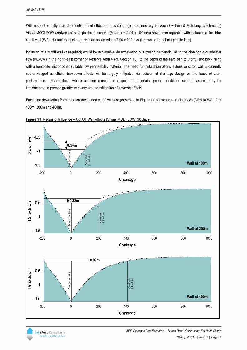
With respect to mitigation of potential offset effects of dewatering (e.g. connectivity between Okohine & Motutangi catchments)
Visual MODLFOW analyses of a single drain scenario (Mean k = 2.94 x 10⁻⁷ m/s) have been repeated with inclusion a 1m thick
cutoff wall (WALL boundary package), with an assumed k = 2.94 x 10⁻⁹ m/s (i.e. two orders of magnitude less).
Inclusion of a cutoff wall (if required) would be achievable via excavation of a trench perpendicular to the direction groundwater
flow (NE-SW) in the north-east corner of Reserve Area 4 (cf. Section 10), to the depth of the hard pan (c.0.5m), and back filling
with a bentonite mix or other suitable low permeability material. The need for installation of any extensive cutoff wall is currently
not envisaged as offsite drawdown effects will be largely mitigated via revision of drainage design on the basis of drain
performance. Nonetheless, where concern remains in respect of uncertain ground conditions such measures may be
implemented to provide greater certainty around mitigation of adverse effects.
Effects on dewatering from the aforementioned cutoff wall are presented in Figure 11, for separation distances (DRN to WALL) of
100m, 200m and 400m.
Figure 11 Radius of Influence – Cut Off Wall effects (Visual MODFLOW; 30 days)
Wall at 100m
-200 0 200 400 600 800 1000
Dra
in (
to h
ard
pan)
Cut
off W
all
(to
hard
pan
)
-200 0 200 400 600 800 1000
-200 0 200 400 600 800 1000
Wall at 200m
Wall at 400m
Dra
in (
to h
ard
pan)
Dra
in (
to h
ard
pan)
Cut
off W
all
(to
hard
pan
)
Cut
off W
all
(to
hard
pan
)
0.54m
0.32m
0.07m

Job Ref: 16325
AEE: Proposed Peat Extraction | Norton Road, Kaimaumau, Far North District
18 August 2017 | Rev. C | Page 32
12.1 Detailed Hydrogeology Discussion
Quantitative drawdown analyses have been revised on the basis of the reported hydraulic characterisation (Section 11, and have
been applied to general site conditions for dewatering of target peat areas. On the basis of the observed ground conditions and
Visual MODLFOW assessment the follow conclusions are made in respect of a deposit of infinite extent and uniform thickness
(3m):
• A single drain excavated to a depth of 3m is anticipated to have an appreciable radius of influence (i.e. distance to 0m
drawdown) of approximately 600m;
• The majority of drawdown is achieved within 30 days, however effects continue to increase in distance up to
approximately 365 days;
• Negligible difference in drawdown radii are reported for upper and lower bound hydraulic conductivities (Table 8);
• A composite cone of depression (Figure 10) resulting from installation of a second drain at 200m spacing is observable
to a distance of 300m, however is considered negligible;
• Where mitigation of drawdown effects is required, use of a cutoff wall (e.g. low permeability curtain) within 200m of the
respective drain is anticipated to reduce proximal drawdown by approximately 60% (cf. Figure 11). In the context of the
site, a low permeability wall would be comprised of material in the order of 1 x 10⁻⁹ m/s, being 2 orders of magnitude
less than the average permeability of the surrounding interdune peats.
With reference to potential minor subsurface connection (Section 10) identified in the north-eastern corner of the proposed
extraction area backfilling of a single trench across the groundwater gradient is anticipated to provide a sufficient barrier to
mitigate adverse flow between the Okohine and Motutangi catchments.
13 Environmental Screening
13.1 PASS Field Screening
Observations made during our Stage 1 site walkover in June 2016, indicated that potential for the presence of Acid Sulphate Soils
(ASS) across the site (cf. Section 6). In order to a provide semi-quantitative assessment of the presence of Potential ASS
(PASS) across the proposed extractions areas, soils samples have been collected from several locations across the site during
our Stage 2 investigation (May 2017) and screened for acid sulphate presence using the pHField/pHFOX (“Field/Fox”) reactivity
testing method (Hey, 2002: Field Testing, Sampling and Safety for Acid Sulfate Soils; Watling, Ahern & Hey: Acid Sulfate Soil
Field pH Tests).
At each location two (2) samples have been collected from below the standing water table (i.e. unoxised state). Sampling
locations have been chosen primarily on the basis of visible PASS indicators, as observed during the previous walkover, and
discussed in Section 6. Sampling locations are shown in Figure 12. Results of Field/Fox testing are presented in Table 9.
While it is acknowledged that Field/Fox testing cannot conclusively eliminate the potential for ASS soils across the site, it is
considered that the observed staining/discolouration, based on field screening, is unlikely to be related to the presence of Acid
sulfate. The recorded reactions are noted as being, at least in partly, resulting from peroxide reaction with organic matter.
At this stage, and in absence of more prolonged or apparent indicators, further assessment of PASS is not considered warranted.

Job Ref: 16325
AEE: Proposed Peat Extraction | Norton Road, Kaimaumau, Far North District
18 August 2017 | Rev. C | Page 33
The potential for adverse effects arising from the presence of acid sulfate soils is considered negligible.
Table 9: Acid Sulfate Soil Field pH Testing
Sample Location Sample Depth pH Field pH Fox pH Change Soil Reaction Rating (1)
PZ01 (AH05) 0.5 2.74 2.42 0.32 X – Slight
1.0 2.86 2.59 0.27 X – Slight
PZ02
0.5 3.35 2.72 0.63 X - Slight
1.0a 3.81 2.72 1.09 X – Slight
1.0b 3.42 2.56 0.86 X – Slight
PZ04 0.5 3.75 3.23 0.52 X – Slight (1)
1.0 4.16 3.69 0.47 X – Slight
AH02 0.5 3.01 2.14 0.87 X – Slight (1)
1.0 3.75 3.27 0.48 X – Slight
AH04 0.5 2.95 2.62 0.33 X – Slight
1.0 3.38 2.89 0.49 X – Slight
Table Notes: (1) Reaction scale as reported Table H1.1 (Watling, Ahern & Hey: Acid Sulfate Soil Field pH Tests) (2) Significant “frothing” – indicative of reaction with organic matter
Figure 12 Acid Sulfate Screening Locations
N Reserve Area 4
Salles/K
aurex D
rain
Airstrip
Rd
Reserve Area 2
Reserve Area 3
Reserve Area 1

Job Ref: 16325
AEE: Proposed Peat Extraction | Norton Road, Kaimaumau, Far North District
18 August 2017 | Rev. C | Page 34
13.2 Baseline Monitoring
Baseline environmental measurements have been collected from eight (8) locations across the site an surrounding environment.
Collection of baseline measurements has included installation of five (5) permanent reference markers, comprised of driven steel
marker-posts. All locations have been located by means of hand GPS (GPS/GLONASS). Baseline monitoring locations are
presented in Table 10, and as shown in Figure 13 and Plates 5 to 8. Baseline readings are presented in Table 11.
Table 10: Baseline Monitoring Locations
Location ID NZTM (m)
Permanent Markers Northing Easting
DS Estuary 6134179.5 1620985.1 N
Kaurex US (2) 6136794.2 1619555.4 Y
Kaurex US-B 6136762.2 1619579.8 N
Pond 6134934.7 1619853.5 Y
Kaurex Mid (2) 6135337.5 1619794.4 Y
US Estuary 6134314.8 1619520.9 N
Waikaramu DRN 6135080.4 1620083.2 Y
PZ04 (1) 6135727.1 1619903.3 Y
Table Notes: DS: Downstream US: Upstream Kaurex: Kaurex/Salles Drain Waikaramu: Waikaramu Drain Estuary: Waiparera Stream (1) PZ04 location includes both GW & surface water measurement (2) Locations identical to previous Radon analyses undertaken by Williamson Water Advisory, May 2017 (Motutangi-Waiharara Groundwater Model, Factual Technical Report – Modelling; WWA0026, Rev. 5)
Table 11: Baseline Readings
Location ID DO
(%)
Temp.
(˚C) pH
Conductivity (µS/-cm) ORP (mV)
Flow
SPC C m/s (1) m³/s Direction
DS Estuary 81 15.8 5.64 8920 7350 210 Tidal
Kaurex US 33 15.9 2.74 382 313 No measurable flow
Kaurex US-B 17 17.4 2.78 376 321 No measurable flow
Pond 62 15.5 3.24 346 283
Kaurex Mid 54 14.8 3.35 353 284 0.045 0.043 south
US Estuary 70 15.0 5.42 523 424 210 0.0708 0.0991 east
Waikaramu DRN 44 13.2 3.09 394 304 284 0.007 0.001 west
PZ04 – Groundwater 86 14.4 4.00 191 155 357
PZ04 – Pond 20 15.4 3.82 166 136 276
Table Notes: (1) Maximum recorded flow rate

Job Ref: 16325
AEE: Proposed Peat Extraction | Norton Road, Kaimaumau, Far North District
18 August 2017 | Rev. C | Page 35
Figure 13 Baseline Monitoring Locations
Baseline readings have been recorded using YSI ProPlus Multimeter. Equipment has been calibrated by the supplier prior to use,
and has been field calibrated between successive days of fieldwork in May 2017. Measurements of flow (where recorded) have
been made using a Sontek Flow Tracker Handheld ADV.
N

Job Ref: 16325
AEE: Proposed Peat Extraction | Norton Road, Kaimaumau, Far North District
18 August 2017 | Rev. C | Page 36
Plate 5 Kaurex US Monitoring Point (facing south/”downstream”)
Plate 6 Kaurex Mid Monitoring Point (facing south/downstream)
PZ01 Kaurex US Monitoring Point
Kaurex US-B
Kaurex Mid Monitoring Point
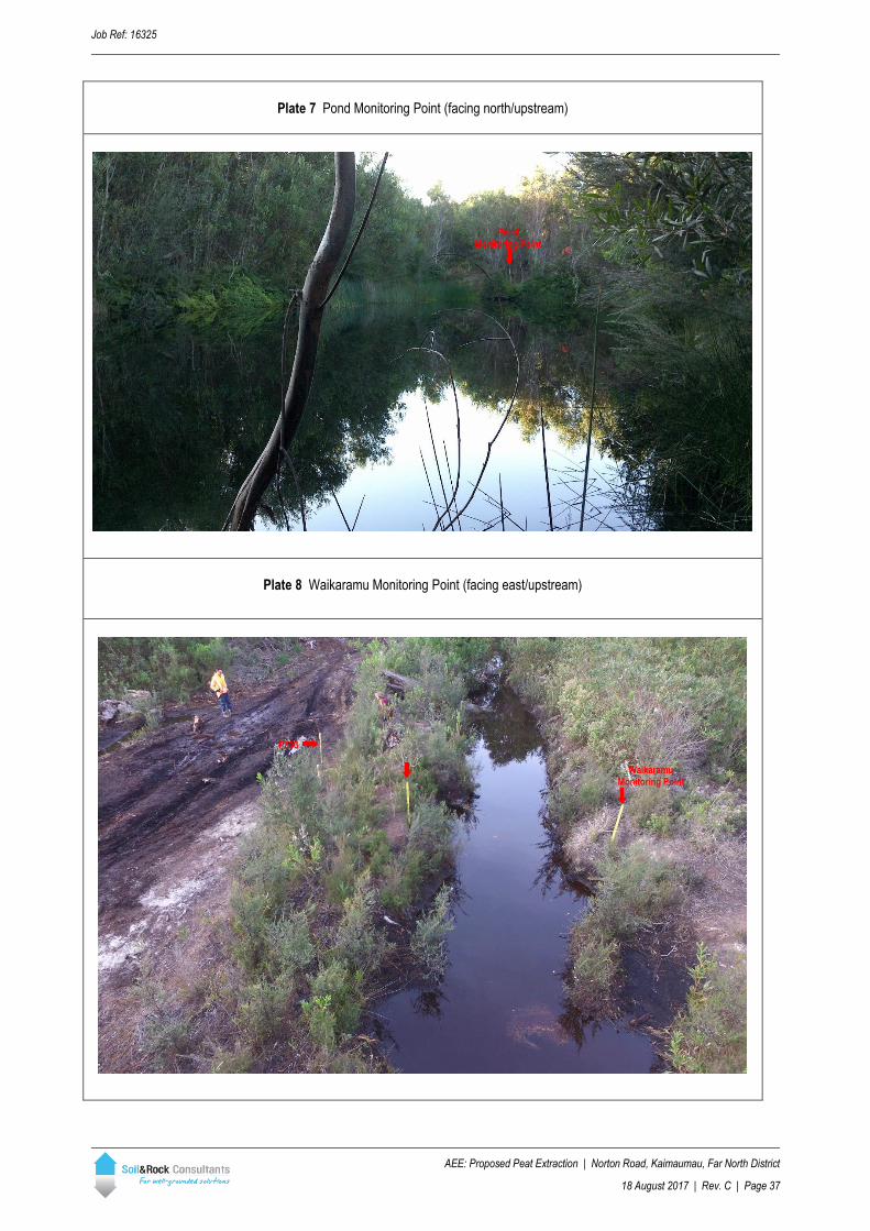
Job Ref: 16325
AEE: Proposed Peat Extraction | Norton Road, Kaimaumau, Far North District
18 August 2017 | Rev. C | Page 37
Plate 7 Pond Monitoring Point (facing north/upstream)
Plate 8 Waikaramu Monitoring Point (facing east/upstream)
`
Pond Monitoring Point
Waikaramu Monitoring Point
PZ03

Job Ref: 16325
AEE: Proposed Peat Extraction | Norton Road, Kaimaumau, Far North District
18 August 2017 | Rev. C | Page 38
14 Recommendations
Based on the adopted groundwater model for the area of the proposed peat extraction is not anticipated that the proposed activity
will have more than minor hydrological or hydrogeological effect, if any, on the adjacent Scientific Reserve or Lake Waikaramu.
Additional assessments of constructed drain performance are recommended to be undertaken at the commencement of
dewatering activities, and should be used to refine the proposed and adopted groundwater model.
The radius of influence from dewatering of the proposed drains is anticipated to be interrupted by the adjacent sand units (sand
bars). Area specific assessment will be required in relation to the northeast corner of Reserve Area 4, and should be undertaken
of basis of drain performance following commencement of dewatering across the southern resource areas.
Additional assessment would aid in both optimisation of the drainage grid design, and ensure dewatering effects stay within the
proposed mining tenement (i.e. extraction area).
Following the return of processed peat to the worked over excavation areas, ground levels are anticipated to require some
additional “topping up” with sand and/or topsoil to achieve the proposed ground levels and balance some deficit of material. To
aid in this manner, some areas may be designated for lakes or wetlands, which is envisaged to aid in the ongoing drainage of
arable land post-mining, however specific assessment should be undertaken.
Quantitative assessment of processed peat materials indicates negligible differences in hydraulic parameters. Re-deposition of
processing materials is not anticipated to significantly alter the shallow groundwater regime (i.e. groundwater table) within the
interdune peat deposits.
Drainage of the proposed excavation areas is not considered to be environmentally adverse on the scale of the proposed
development and associated proposed drainage network, however the only identified outfall is the Waiparera Stream to the south
of the site (via existing discharge from the for Salles/Kaurex & Waikaramu drains).
Field screening for the presence of Acid Sulfate Soils (ASS) indicates negligible potential for acid generation, and is considered
sufficient to warrant further assessment.
In summary:
i. The peat soil deposits targeted for extraction are relatively shallow and no adverse effects arising from groundwater
drawdown are anticipated outside of the peats, or extending beyond the surrounding sand ridgelines;
ii. Excavation of drains should not breach the reported hardpan between the peat soils and underlying sand due to the potential
for groundwater inflow to the proposed excavations and drains;
iii. Further delineation of underlying sand paleotopography is recommended around the periphery of the extraction area, in
particular towards the Motutangi Swamp. Alternatively, a buffer zone of not less than 200m may be established against the
Motutangi Swamp (cf. Figure 11; final buffer width may be determined by onsite performance of drains at commencement of
extraction in southern peatlands area);
iv. Processed peat materials, together with additional sand or topsoil may be returned to worked over excavation areas. Post-
excavation landform contouring may incorporate creation of lakes or wetlands, which may assist in long-term surface water
control. Additional assessment of hydrological effects of landform contouring should be undertaken, however processing of
materials is not anticipated to materially alter hydraulic characteristics.
End of Report
Job Ref: 16325
AEE: Proposed Peat Extraction | Norton Road, Kaimaumau, Far North District
18 August 2017 | Rev. C | Appendix A
APPENDIX A:
HYDRAULIC CONDUCTIVITY ANALYSES
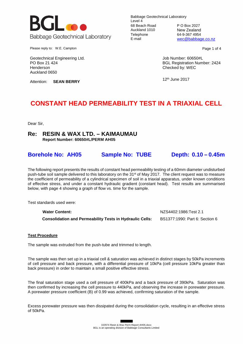
Babbage Geotechnical Laboratory Level 4 68 Beach Road P O Box 2027 Auckland 1010 New Zealand Telephone 64-9-367 4954 E-mail [email protected]
102974 Resin & Wax Perm Report AH05.docx
BGL is an operating division of Babbage Consultants Limited
Please reply to: W.E. Campton Page 1 of 4
Geotechnical Engineering Ltd. PO Box 21 424 Henderson Auckland 0650 Attention: SEAN BERRY
Job Number: 60650#L BGL Registration Number: 2424 Checked by: WEC
12th June 2017
CONSTANT HEAD PERMEABILITY TEST IN A TRIAXIAL CELL Dear Sir,
Re: RESIN & WAX LTD. – KAIMAUMAU Report Number: 60650#L/PERM AH05
Borehole No: AH05 Sample No: TUBE Depth: 0.10 – 0.45m The following report presents the results of constant head permeability testing of a 60mm diameter undisturbed push-tube soil sample delivered to this laboratory on the 31st of May 2017. The client request was to measure the coefficient of permeability of a cylindrical specimen of soil in a triaxial apparatus, under known conditions of effective stress, and under a constant hydraulic gradient (constant head). Test results are summarised below, with page 4 showing a graph of flow vs. time for the sample. Test standards used were: Water Content: NZS4402:1986:Test 2.1
Consolidation and Permeability Tests in Hydraulic C ells: BS1377:1990: Part 6: Section 6
Test Procedure The sample was extruded from the push-tube and trimmed to length. The sample was then set up in a triaxial cell & saturation was achieved in distinct stages by 50kPa increments of cell pressure and back pressure, with a differential pressure of 10kPa (cell pressure 10kPa greater than back pressure) in order to maintain a small positive effective stress. The final saturation stage used a cell pressure of 400kPa and a back pressure of 390kPa. Saturation was then confirmed by increasing the cell pressure to 440kPa, and observing the increase in porewater pressure. A porewater pressure coefficient (B) of 0.99 was achieved, confirming saturation of the sample. Excess porewater pressure was then dissipated during the consolidation cycle, resulting in an effective stress of 50kPa.
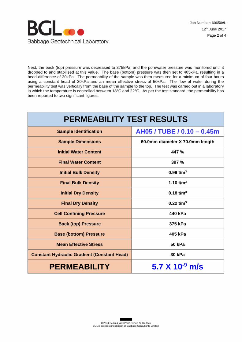
Job Number: 60650#L
12th June 2017
Page 2 of 4
102974 Resin & Wax Perm Report AH05.docx
BGL is an operating division of Babbage Consultants Limited
Next, the back (top) pressure was decreased to 375kPa, and the porewater pressure was monitored until it dropped to and stabilised at this value. The base (bottom) pressure was then set to 405kPa, resulting in a head difference of 30kPa. The permeability of the sample was then measured for a minimum of four hours using a constant head of 30kPa and an mean effective stress of 50kPa. The flow of water during the permeability test was vertically from the base of the sample to the top. The test was carried out in a laboratory in which the temperature is controlled between 18°C and 22°C. As per the test standard, the permeability has been reported to two significant figures.
PERMEABILITY TEST RESULTS
Sample Identification AH05 / TUBE / 0.10 – 0.45m
Sample Dimensions 60.0mm diameter X 70.0mm length
Initial Water Content 447 %
Final Water Content 397 %
Initial Bulk Density 0.99 t/m 3
Final Bulk Density 1.10 t/m 3
Initial Dry Density 0.18 t/m 3
Final Dry Density 0.22 t/m 3
Cell Confining Pressure 440 kPa
Back (top) Pressure 375 kPa
Base (bottom) Pressure 405 kPa
Mean Effective Stress 50 kPa
Constant Hydraulic Gradient (Constant Head) 30 kPa
PERMEABILITY 5.7 X 10⁻⁹ m/s
Job Number: 60650#L
12th June 2017
Page 3 of 4
102974 Resin & Wax Perm Report AH05.docx
BGL is an operating division of Babbage Consultants Limited
Sample Description (not part of BGL IANZ Accreditation) PEAT, fibrous, common wood fragments, plastic, black with brown mottles, very moist, low density. Please note that the test results relate only to the sample under test. Thank you for the opportunity to carry out this testing. If you have any queries regarding the content of this report, please contact the undersigned at your convenience. Yours faithfully, Justin Franklin Signatory (Assistant Laboratory Manager) Babbage Geotechnical Laboratory
All tests reported herein have been performed in accordance with the laboratory’s scope of accreditation. This report may not be reproduced except in full & with written approval from BGL.

Job No:
Reg. No:
Tested By: JF
Compiled By: JF
Checked By: WEC
Borehole No: Sample No: Depth:
Head Difference = 30 kPa Effective Stress = 50 kPa
Coefficient of Permeability (k) = m/s
9.47
0.00
2.34
120
180
240
0
60
4.59
7.03
June 2017
Version 2, Issued Apr-12
TUBE
CONSTANT HEAD PERMEABILITY TEST
(minutes)
Cumulative Volume
BS1377:1990: Part 6: Section 6 / NZS4402: 1986: Test 2.112/06/2017
12/06/2017
AH05
TIME
(minutes) Change (mL)
TIME
60650#L/PERM AH05
0.10 - 0.45m
60650#L
2424
PROJECT: RESIN & WAX LTD. - KAIMAUMAU
Page 4 of 4Report No:
5.7 X 10⁻⁹
Cumulative Volume
Change (mL)
0.0
2.0
4.0
6.0
8.0
10.0
0 30 60 90 120 150 180 210 240
Cu
mu
lati
ve V
olu
me
Ch
ang
e (
mL
)
Time (minutes)
Flow vs. Time Graph
12/06/2017 W:\Laboratory\LAB JOBS CURRENT\60650#L Soil & Rock Resin & Wax Ltd. - Kaimaumau\AH05\AH05 PERM.xlsx

Babbage Geotechnical Laboratory Level 4 68 Beach Road P O Box 2027 Auckland 1010 New Zealand Telephone 64-9-367 4954 E-mail [email protected]
102973 Resin & Wax Perm Report PZ04.docx
BGL is an operating division of Babbage Consultants Limited
Please reply to: W.E. Campton Page 1 of 4
Geotechnical Engineering Ltd. PO Box 21 424 Henderson Auckland 0650 Attention: SEAN BERRY
Job Number: 60650#L BGL Registration Number: 2424 Checked by: WEC
7th June 2017
CONSTANT HEAD PERMEABILITY TEST IN A TRIAXIAL CELL Dear Sir,
Re: RESIN & WAX LTD. – KAIMAUMAU Report Number: 60650#L/PERM PZ04
Borehole No: PZ04 Sample No: TUBE Depth: 0.20 – 0.60m The following report presents the results of constant head permeability testing of a 60mm diameter undisturbed push-tube soil sample delivered to this laboratory on the 31st of May 2017. The client request was to measure the coefficient of permeability of a cylindrical specimen of soil in a triaxial apparatus, under known conditions of effective stress, and under a constant hydraulic gradient (constant head). Test results are summarised below, with page 4 showing a graph of flow vs. time for the sample. Test standards used were: Water Content: NZS4402:1986:Test 2.1
Consolidation and Permeability Tests in Hydraulic C ells: BS1377:1990: Part 6: Section 6
Test Procedure The sample was extruded from the push-tube and trimmed to length. The sample was then set up in a triaxial cell & saturation was achieved in distinct stages by 50kPa increments of cell pressure and back pressure, with a differential pressure of 10kPa (cell pressure 10kPa greater than back pressure) in order to maintain a small positive effective stress. The final saturation stage used a cell pressure of 400kPa and a back pressure of 390kPa. Saturation was then confirmed by increasing the cell pressure to 440kPa, and observing the increase in porewater pressure. A porewater pressure coefficient (B) of 1.04 was achieved, confirming saturation of the sample. Excess porewater pressure was then dissipated during the consolidation cycle, resulting in an effective stress of 50kPa.

Job Number: 60650#L
7th June 2017
Page 2 of 4
102973 Resin & Wax Perm Report PZ04.docx
BGL is an operating division of Babbage Consultants Limited
Next, the back (top) pressure was decreased to 375kPa, and the porewater pressure was monitored until it dropped to and stabilised at this value. The base (bottom) pressure was then set to 405kPa, resulting in a head difference of 30kPa. The permeability of the sample was then measured for a minimum of four hours using a constant head of 30kPa and an mean effective stress of 50kPa. The flow of water during the permeability test was vertically from the base of the sample to the top. The test was carried out in a laboratory in which the temperature is controlled between 18°C and 22°C. As per the test standard, the permeability has been reported to two significant figures.
PERMEABILITY TEST RESULTS
Sample Identification PZ04 / TUBE / 0.20 – 0.60m
Sample Dimensions 60.0mm diameter X 85.0mm length
Initial Water Content 53.2 %
Final Water Content 53.3 %
Initial Bulk Density 1.54 t/m 3
Final Bulk Density 1.57 t/m 3
Initial Dry Density 1.01 t/m 3
Final Dry Density 1.03 t/m 3
Cell Confining Pressure 440 kPa
Back (top) Pressure 375 kPa
Base (bottom) Pressure 405 kPa
Mean Effective Stress 50 kPa
Constant Hydraulic Gradient (Constant Head) 30 kPa
PERMEABILITY 2.2 X 10⁻⁶ m/s

Job Number: 60650#L
7th June 2017
Page 3 of 4
102973 Resin & Wax Perm Report PZ04.docx
BGL is an operating division of Babbage Consultants Limited
Sample Description (not part of BGL IANZ Accreditation) PEAT, amorphous with occasional wood & rootlets, fine sandy, non-plastic, black, moist, friable. Please note that the test results relate only to the sample under test. Thank you for the opportunity to carry out this testing. If you have any queries regarding the content of this report, please contact the undersigned at your convenience. Yours faithfully, Justin Franklin Signatory (Assistant Laboratory Manager) Babbage Geotechnical Laboratory
All tests reported herein have been performed in accordance with the laboratory’s scope of accreditation. This report may not be reproduced except in full & with written approval from BGL.

Job No:
Reg. No:
Tested By: JF
Compiled By: JF
Checked By: WEC
Borehole No: Sample No: Depth:
Head Difference = 30 kPa Effective Stress = 50 kPa
Coefficient of Permeability (k) = m/s
0.00
9.27
0.00
0.68
June 2017
Version 2, Issued Apr-12
TUBE
CONSTANT HEAD PERMEABILITY TEST
(minutes)
Cumulative Volume
BS1377:1990: Part 6: Section 6 / NZS4402: 1986: Test 2.16/06/2017
7/06/2017
PZ04
TIME
(minutes) Change (mL)
TIME
60650#L/PERM PZ04
0.20 - 0.60m
60650#L
2424
PROJECT: RESIN & WAX LTD. - KAIMAUMAU
Page 4 of 4Report No:
2.2 X 10⁻⁶
Cumulative Volume
Change (mL)
0.0
1.0
2.0
3.0
4.0
5.0
6.0
7.0
8.0
9.0
10.0
0.00 0.10 0.20 0.30 0.40 0.50 0.60 0.70 0.80 0.90 1.00
Cu
mu
lati
ve V
olu
me
Ch
ang
e (
mL
)
Time (minutes)
Flow vs. Time Graph
7/06/2017 W:\Laboratory\LAB JOBS CURRENT\60650#L Soil & Rock Resin & Wax Ltd. - Kaimaumau\PZ04\PZ04 PERM.xlsx
Babbage Geotechnical Laboratory Level 4 68 Beach Road P O Box 2027 Auckland 1010 New Zealand Telephone 64-9-367 4954 E-mail [email protected]
102971 Resin & Wax Perm Report SP01.docx
BGL is an operating division of Babbage Consultants Limited
Please reply to: W.E. Campton Page 1 of 4
Geotechnical Engineering Ltd. PO Box 21 424 Henderson Auckland 0650 Attention: SEAN BERRY
Job Number: 60650#L BGL Registration Number: 2424 Checked by: WEC
9th June 2017
CONSTANT HEAD PERMEABILITY TEST IN A TRIAXIAL CELL Dear Sir,
Re: RESIN & WAX LTD. – KAIMAUMAU Report Number: 60650#L/PERM SP01
Borehole No: SP01 Sample No: BULK The following report presents the results of constant head permeability testing of a bulk soil sample delivered to this laboratory on the 31st of May 2017. The client request was to measure the coefficient of permeability of a compacted cylindrical specimen of soil in a triaxial apparatus, under known conditions of effective stress, and under a constant hydraulic gradient (constant head). Test results are summarised below, with page 4 showing a graph of flow vs. time for the sample. Test standards used were: Water Content: NZS4402:1986:Test 2.1
NZ Standard Compaction – Single Point: NZS4402:1986:Test 4.1.1
Consolidation and Permeability Tests in Hydraulic C ells: BS1377:1990: Part 6: Section 6
Test Procedure The sample was compacted into a proctor mould at natural water content following test specification NZS4402:1986:Test 4.1.1 – Standard Compaction. The sample was then set up in a triaxial cell & saturation was achieved in distinct stages by 50kPa increments of cell pressure and back pressure, with a differential pressure of 10kPa (cell pressure 10kPa greater than back pressure) in order to maintain a small positive effective stress. The final saturation stage used a cell pressure of 400kPa and a back pressure of 390kPa. Saturation was then confirmed by increasing the cell pressure to 440kPa, and observing the increase in porewater pressure. A porewater pressure coefficient (B) of 1.06 was achieved, confirming saturation of the sample.

Job Number: 60650#L
9th June 2017
Page 2 of 4
102971 Resin & Wax Perm Report SP01.docx
BGL is an operating division of Babbage Consultants Limited
Excess porewater pressure was then dissipated during the consolidation cycle, resulting in an effective stress of 50kPa. Next, the back (top) pressure was decreased to 375kPa, and the porewater pressure was monitored until it dropped to and stabilised at this value. The base (bottom) pressure was then set to 405kPa, resulting in a head difference of 30kPa. The permeability of the sample was then measured for a minimum of four hours using a constant head of 30kPa and an mean effective stress of 50kPa. The flow of water during the permeability test was vertically from the base of the sample to the top. The test was carried out in a laboratory in which the temperature is controlled between 18°C and 22°C. As per the test standard, the permeability has been reported to two significant figures.
PERMEABILITY TEST RESULTS
Sample Identification SP01 / BULK
Sample Dimensions 105.02mm diameter X 114.87mm length
Initial Water Content 125 %
Final Water Content 133 %
Initial Bulk Density 1.12 t/m 3
Final Bulk Density 1.19 t/m 3
Initial Dry Density 0.50 t/m 3
Final Dry Density 0.51 t/m 3
Cell Confining Pressure 440 kPa
Back (top) Pressure 375 kPa
Base (bottom) Pressure 405 kPa
Mean Effective Stress 50 kPa
Constant Hydraulic Gradient (Constant Head) 30 kPa
PERMEABILITY 6.8 X 10⁻⁸ m/s
Job Number: 60650#L
9th June 2017
Page 3 of 4
102971 Resin & Wax Perm Report SP01.docx
BGL is an operating division of Babbage Consultants Limited
Sample Description (not part of BGL IANZ Accreditation) PEAT, fibrous, some fine sand, non-plastic, black with brown patches, slightly moist, low density, very friable, occasional wood fragments. Please note that the test results relate only to the sample under test. Thank you for the opportunity to carry out this testing. If you have any queries regarding the content of this report, please contact the undersigned at your convenience. Yours faithfully, Justin Franklin Signatory (Assistant Laboratory Manager) Babbage Geotechnical Laboratory
All tests reported herein have been performed in accordance with the laboratory’s scope of accreditation. This report may not be reproduced except in full & with written approval from BGL.

Job No:
Reg. No:
Tested By: JF
Compiled By: JF
Checked By: WEC
Borehole No: Sample No: Depth:
Head Difference = 30 kPa Effective Stress = 50 kPa
Coefficient of Permeability (k) = m/s
99.45
0.00
25.10
53
81
106
0
26
50.21
75.31
June 2017
Version 2, Issued Apr-12
BULK
CONSTANT HEAD PERMEABILITY TEST
(minutes)
Cumulative Volume
BS1377:1990: Part 6: Section 6 / NZS4402: 1986: Test 2.19/06/2017
9/06/2017
SP01
TIME
(minutes) Change (mL)
TIME
60650#L/PERM SP01
-
60650#L
2424
PROJECT: RESIN & WAX LTD. - KAIMAUMAU
Page 4 of 4Report No:
6.8 X 10⁻⁸
Cumulative Volume
Change (mL)
0
10
20
30
40
50
60
70
80
90
100
110
120
0 20 40 60 80 100 120
Cu
mu
lati
ve V
olu
me
Ch
ang
e (
mL
)
Time (minutes)
Flow vs. Time Graph
9/06/2017 W:\Laboratory\LAB JOBS CURRENT\60650#L Soil & Rock Resin & Wax Ltd. - Kaimaumau\SP01\SP01 PERM.xlsx

Babbage Geotechnical Laboratory Level 4 68 Beach Road P O Box 2027 Auckland 1010 New Zealand Telephone 64-9-367 4954 E-mail [email protected]
102972 Resin & Wax Perm Report SP02.docx
BGL is an operating division of Babbage Consultants Limited
Please reply to: W.E. Campton Page 1 of 4
Geotechnical Engineering Ltd. PO Box 21 424 Henderson Auckland 0650 Attention: SEAN BERRY
Job Number: 60650#L BGL Registration Number: 2424 Checked by: WEC
12th June 2017
CONSTANT HEAD PERMEABILITY TEST IN A TRIAXIAL CELL Dear Sir,
Re: RESIN & WAX LTD. – KAIMAUMAU Report Number: 60650#L/PERM SP02
Borehole No: SP02 Sample No: BULK The following report presents the results of constant head permeability testing of a bulk soil sample delivered to this laboratory on the 31st of May 2017. The client request was to measure the coefficient of permeability of a compacted cylindrical specimen of soil in a triaxial apparatus, under known conditions of effective stress, and under a constant hydraulic gradient (constant head). Test results are summarised below, with page 4 showing a graph of flow vs. time for the sample. Test standards used were: Water Content: NZS4402:1986:Test 2.1
NZ Standard Compaction – Single Point: NZS4402:1986:Test 4.1.1
Consolidation and Permeability Tests in Hydraulic C ells: BS1377:1990: Part 6: Section 6
Test Procedure The sample was compacted into a proctor mould at natural water content following test specification NZS4402:1986:Test 4.1.1 – Standard Compaction. The sample was then set up in a triaxial cell & saturation was achieved in distinct stages by 50kPa increments of cell pressure and back pressure, with a differential pressure of 10kPa (cell pressure 10kPa greater than back pressure) in order to maintain a small positive effective stress. The final saturation stage used a cell pressure of 400kPa and a back pressure of 390kPa. Saturation was then confirmed by increasing the cell pressure to 440kPa, and observing the increase in porewater pressure. A porewater pressure coefficient (B) of 0.97 was achieved, confirming saturation of the sample.
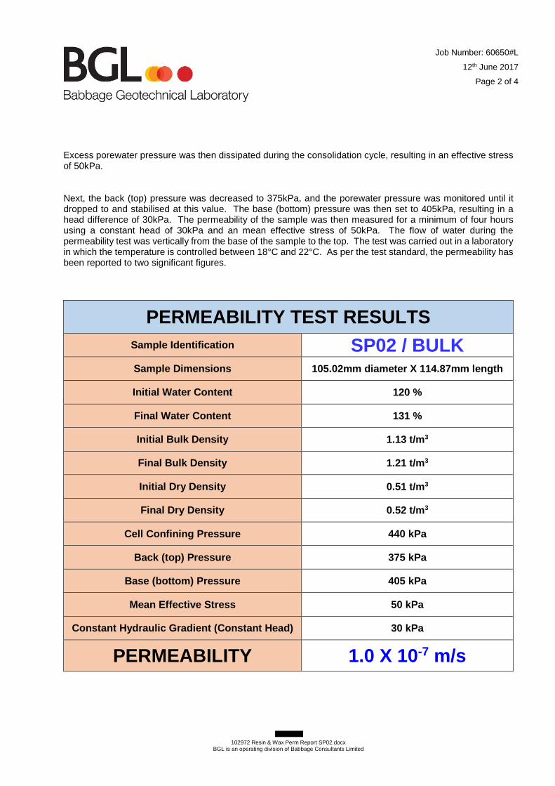
Job Number: 60650#L
12th June 2017
Page 2 of 4
102972 Resin & Wax Perm Report SP02.docx
BGL is an operating division of Babbage Consultants Limited
Excess porewater pressure was then dissipated during the consolidation cycle, resulting in an effective stress of 50kPa. Next, the back (top) pressure was decreased to 375kPa, and the porewater pressure was monitored until it dropped to and stabilised at this value. The base (bottom) pressure was then set to 405kPa, resulting in a head difference of 30kPa. The permeability of the sample was then measured for a minimum of four hours using a constant head of 30kPa and an mean effective stress of 50kPa. The flow of water during the permeability test was vertically from the base of the sample to the top. The test was carried out in a laboratory in which the temperature is controlled between 18°C and 22°C. As per the test standard, the permeability has been reported to two significant figures.
PERMEABILITY TEST RESULTS
Sample Identification SP02 / BULK
Sample Dimensions 105.02mm diameter X 114.87mm length
Initial Water Content 120 %
Final Water Content 131 %
Initial Bulk Density 1.13 t/m 3
Final Bulk Density 1.21 t/m 3
Initial Dry Density 0.51 t/m 3
Final Dry Density 0.52 t/m 3
Cell Confining Pressure 440 kPa
Back (top) Pressure 375 kPa
Base (bottom) Pressure 405 kPa
Mean Effective Stress 50 kPa
Constant Hydraulic Gradient (Constant Head) 30 kPa
PERMEABILITY 1.0 X 10⁻⁷ m/s
Job Number: 60650#L
12th June 2017
Page 3 of 4
102972 Resin & Wax Perm Report SP02.docx
BGL is an operating division of Babbage Consultants Limited
Sample Description (not part of BGL IANZ Accreditation) PEAT, fibrous, non-plastic, black with brown patches, slightly moist, low density, very friable, occasional wood fragments. Please note that the test results relate only to the sample under test. Thank you for the opportunity to carry out this testing. If you have any queries regarding the content of this report, please contact the undersigned at your convenience. Yours faithfully, Justin Franklin Signatory (Assistant Laboratory Manager) Babbage Geotechnical Laboratory
All tests reported herein have been performed in accordance with the laboratory’s scope of accreditation. This report may not be reproduced except in full & with written approval from BGL.
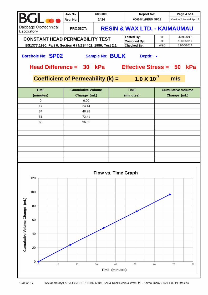
Job No:
Reg. No:
Tested By: JF
Compiled By: JF
Checked By: WEC
Borehole No: Sample No: Depth:
Head Difference = 30 kPa Effective Stress = 50 kPa
Coefficient of Permeability (k) = m/s
96.55
0.00
24.14
34
51
68
0
17
48.28
72.41
June 2017
Version 2, Issued Apr-12
BULK
CONSTANT HEAD PERMEABILITY TEST
(minutes)
Cumulative Volume
BS1377:1990: Part 6: Section 6 / NZS4402: 1986: Test 2.112/06/2017
12/06/2017
SP02
TIME
(minutes) Change (mL)
TIME
60650#L/PERM SP02
-
60650#L
2424
PROJECT: RESIN & WAX LTD. - KAIMAUMAU
Page 4 of 4Report No:
1.0 X 10⁻⁷
Cumulative Volume
Change (mL)
0
20
40
60
80
100
120
0 10 20 30 40 50 60 70 80
Cu
mu
lati
ve V
olu
me
Ch
ang
e (
mL
)
Time (minutes)
Flow vs. Time Graph
12/06/2017 W:\Laboratory\LAB JOBS CURRENT\60650#L Soil & Rock Resin & Wax Ltd. - Kaimaumau\SP02\SP02 PERM.xlsx

Slug Test Analysis Report
Project: Kaimaumau Peatlands
Number: 16325
Client: Resin & Wax Holdings Ltd
Soil & Rock ConsultantsPO Box 21 424HendersonWaitakere 0650New Zealand
Location: Kaimaumau, NZ Slug Test: PZ01 Test Well: PZ01
Test Conducted by: J. Healey Test Date: 25/05/2017
Analysis Performed by: S. Berry PZ01 - Bouwer Rice Analysis Date: 1/06/2017
Aquifer Thickness: 2.50 m
0 14000 28000 42000 56000 70000
Time [s]
1E-2
1E-1
1E0
h/h
0
Calculation using Bouwer & Rice
Observation Well Hydraulic Conductivity
[m/s]
PZ01 1.00 × 10⁻⁸

Slug Test Analysis Report
Project: Kaimaumau Peatlands
Number: 16325
Client: Resin & Wax Holdings Ltd
Soil & Rock ConsultantsPO Box 21 424HendersonWaitakere 0650New Zealand
Location: Kaimaumau, NZ Slug Test: PZ01 Test Well: PZ01
Test Conducted by: J. Healey Test Date: 25/05/2017
Analysis Performed by: S. Berry PZ01 - Hvorslev Analysis Date: 1/06/2017
Aquifer Thickness: 2.50 m
0 14000 28000 42000 56000 70000
Time [s]
1E-2
1E-1
1E0
h/h
0
Calculation using Hvorslev
Observation Well Hydraulic Conductivity
[m/s]
PZ01 1.43 × 10⁻⁸

Slug Test Analysis Report
Project: Kaimaumau Peatlands
Number: 16325
Client: Resin & Wax Holdings Ltd
Soil & Rock ConsultantsPO Box 21 424HendersonWaitakere 0650New Zealand
Location: Kaimaumau, NZ Slug Test: PZ01 Test Well: PZ01
Test Conducted by: J. Healey Test Date: 25/05/2017
Analysis Performed by: S. Berry PZ01 - Dagan Analysis Date: 23/06/2017
Aquifer Thickness: 2.50 m
0 14000 28000 42000 56000 70000
Time [s]
1E-2
1E-1
1E0
h/h
0
Calculation using Dagan
Observation Well Hydraulic Conductivity
[m/s]
PZ01 1.09 × 10⁻⁸
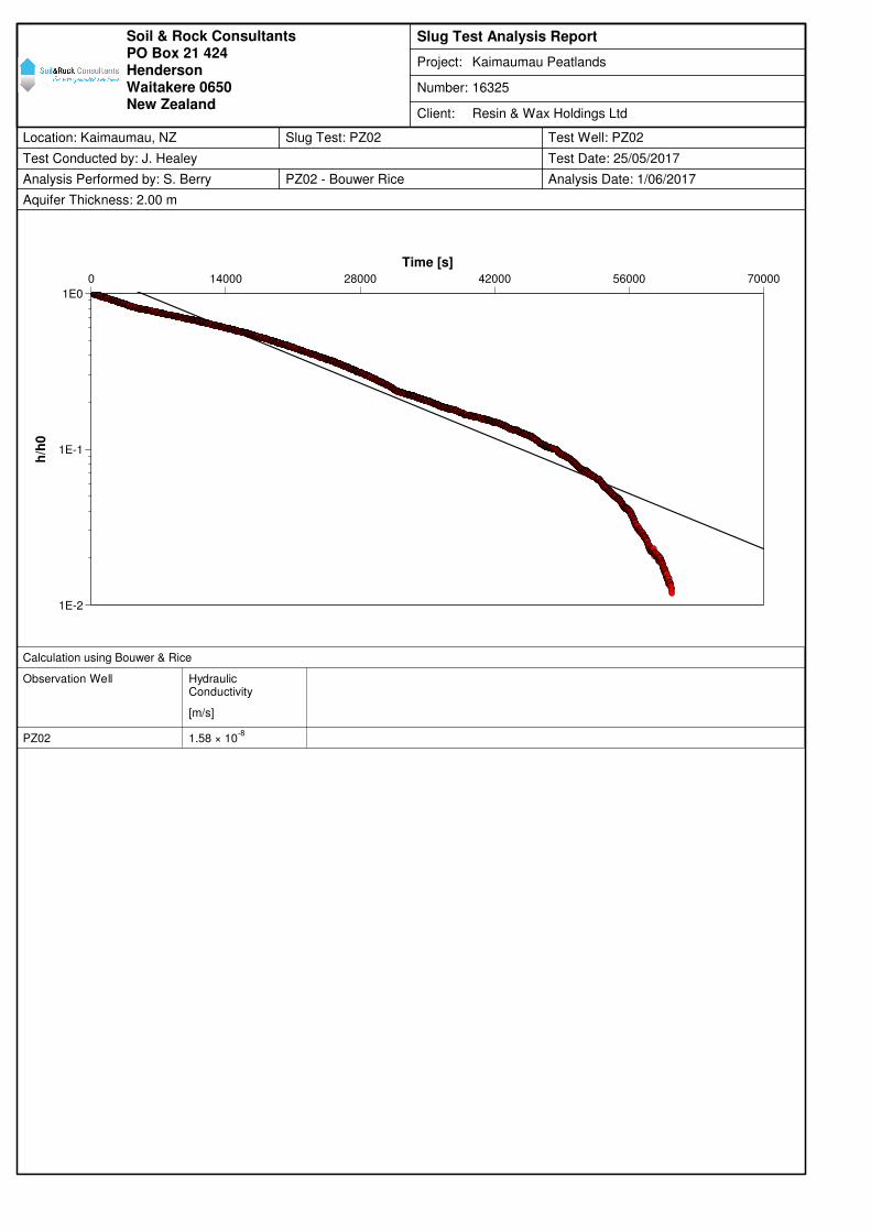
Slug Test Analysis Report
Project: Kaimaumau Peatlands
Number: 16325
Client: Resin & Wax Holdings Ltd
Soil & Rock ConsultantsPO Box 21 424HendersonWaitakere 0650New Zealand
Location: Kaimaumau, NZ Slug Test: PZ02 Test Well: PZ02
Test Conducted by: J. Healey Test Date: 25/05/2017
Analysis Performed by: S. Berry PZ02 - Bouwer Rice Analysis Date: 1/06/2017
Aquifer Thickness: 2.00 m
0 14000 28000 42000 56000 70000
Time [s]
1E-2
1E-1
1E0
h/h
0
Calculation using Bouwer & Rice
Observation Well Hydraulic Conductivity
[m/s]
PZ02 1.58 × 10⁻⁸

Slug Test Analysis Report
Project: Kaimaumau Peatlands
Number: 16325
Client: Resin & Wax Holdings Ltd
Soil & Rock ConsultantsPO Box 21 424HendersonWaitakere 0650New Zealand
Location: Kaimaumau, NZ Slug Test: PZ02 Test Well: PZ02
Test Conducted by: J. Healey Test Date: 25/05/2017
Analysis Performed by: S. Berry PZ02 - Hvorslev Analysis Date: 1/06/2017
Aquifer Thickness: 2.00 m
0 14000 28000 42000 56000 70000
Time [s]
1E-2
1E-1
1E0
h/h
0
Calculation using Hvorslev
Observation Well Hydraulic Conductivity
[m/s]
PZ02 2.27 × 10⁻⁸
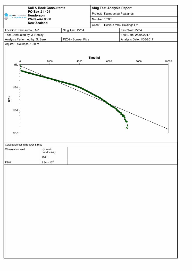
Slug Test Analysis Report
Project: Kaimaumau Peatlands
Number: 16325
Client: Resin & Wax Holdings Ltd
Soil & Rock ConsultantsPO Box 21 424HendersonWaitakere 0650New Zealand
Location: Kaimaumau, NZ Slug Test: PZ04 Test Well: PZ04
Test Conducted by: J. Healey Test Date: 25/05/2017
Analysis Performed by: S. Berry PZ04 - Bouwer Rice Analysis Date: 1/06/2017
Aquifer Thickness: 1.50 m
0 2000 4000 6000 8000 10000
Time [s]
1E-3
1E-2
1E-1
1E0
h/h
0
Calculation using Bouwer & Rice
Observation Well Hydraulic Conductivity
[m/s]
PZ04 2.34 × 10⁻⁷
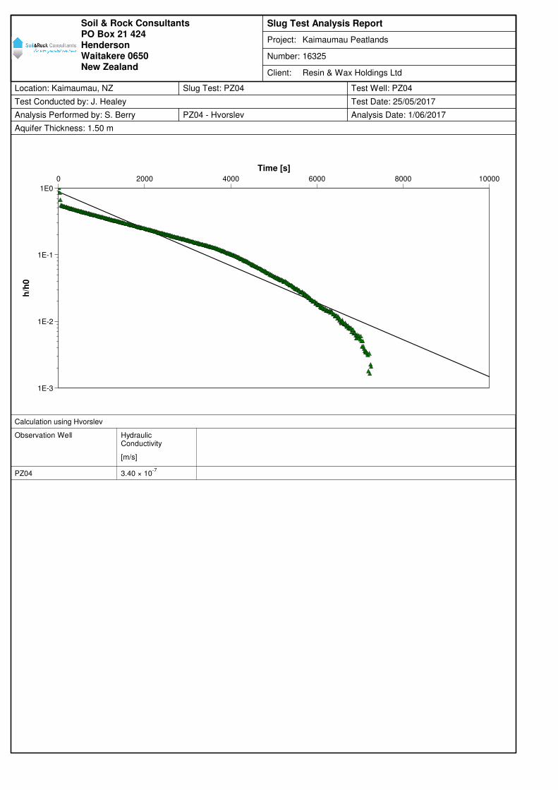
Slug Test Analysis Report
Project: Kaimaumau Peatlands
Number: 16325
Client: Resin & Wax Holdings Ltd
Soil & Rock ConsultantsPO Box 21 424HendersonWaitakere 0650New Zealand
Location: Kaimaumau, NZ Slug Test: PZ04 Test Well: PZ04
Test Conducted by: J. Healey Test Date: 25/05/2017
Analysis Performed by: S. Berry PZ04 - Hvorslev Analysis Date: 1/06/2017
Aquifer Thickness: 1.50 m
0 2000 4000 6000 8000 10000
Time [s]
1E-3
1E-2
1E-1
1E0
h/h
0
Calculation using Hvorslev
Observation Well Hydraulic Conductivity
[m/s]
PZ04 3.40 × 10⁻⁷

Slug Test Analysis Report
Project: Kaimaumau Peatlands
Number: 16325
Client: Resin & Wax Holdings Ltd
Soil & Rock ConsultantsPO Box 21 424HendersonWaitakere 0650New Zealand
Location: Kaimaumau, NZ Slug Test: PZ04 Test Well: PZ04
Test Conducted by: J. Healey Test Date: 25/05/2017
Analysis Performed by: S. Berry PZ04 - CBP Analysis Date: 1/06/2017
Aquifer Thickness: 1.50 m
0 2000 4000 6000 8000 10000
Time [s]
0.00
0.01
0.10
1.00
Ch
an
ge in
wate
r le
vel [m
]
Calculation using Cooper-Bredehoeft-Papadopulos
Observation Well Transmissivity
[m²/s]
Hydraulic Conductivity
[m/s]
Well-bore storage coefficient
PZ04 1.79 × 10⁻⁷
1.19 × 10⁻⁷
2.22 × 10⁻¹