Chris Dore NETCEN, AEA Technology Uncertainty in the UK Heavy Metal Emissions Inventory.

7HFKQRORJ\�3URILOH (0(5*,1*�7(&+12/2*<�352*5$0
7KH 6,7( 3URJUDP DVVHVVHV EXW GRHV QRW
DSSURYH RU HQGRUVH WHFKQRORJLHV�3DJH���
Generalized Flowsheet for the Physical Treatment of Contaminated Soil
AEA TECHNOLOGY ENVIRONMENT(Incorporating UK National Environmental Technology Centre)
(Soil Separation and Washing Process)
TECHNOLOGY DESCRIPTION: software designed to reconcile material flow data.
AEA Technology Environment (AEA) has recommendations for full-scale continuous flowdeveloped an ex situ soil separation and washing sheets with predicted flows of solids, associatedprocess that uses mineral processing technology contaminant species, and water. Contaminantand hardware. The process can be used (1) as a levels and distributions to the various productsvolume reduction process to release clean soil can also be estimated. Such data are required tofractions and concentrate contaminants, or (2) as estimate the cost and potential success of the full-a pretreatment stage in a treatment train. scale remediation process plant. Flow sheet
Because each contaminated soil is different, AEA address the nature and contamination of each soilhas developed a custom physical treatment or waste. A typical schematic flow sheet of theprocess for soil using a three-stage process: process is shown in the diagram on the previouslaboratory-scale characterization, separation page. The flow sheet involves screening the rawtesting and assessment, and treatment and data feed at 50 millimeters (mm) under powerful wateranalysis. jets to deagglomerate the mass. Debris greater
AEA is experienced in conducting pilot plant Remaining solids and the water are passedtesting programs on contaminated soil and through a drum scrubber that deagglomerates themineral ores. In addition, AEA uses computer mass further because agitation
The results of data processing lead to
configuration is flexible and can be customized to
than 50 mm in size is often decontaminated.

)HEUXDU\�����&RPSOHWHG�3URMHFW
7KH 6,7( 3URJUDP DVVHVVHV EXW GRHV QRW
DSSURYH RU HQGRUVH WHFKQRORJLHV� 3DJH���
is more intense. It breaks down clay lumps and STATUS:adhering material into suspension, except forsurface coatings of clay and oil on fine particles. The technology was accepted into the SITEThe drum scrubber discharge is screened at 1 mm, Emerging Technology Program in July 1991 andand the oversize discharge is screened at 10 mm. completed in 1994. A Final Report was deliveredThe 10 to 50 mm size range is often clean debris; to the U.S. EPA in 1994, and work done with thisif it is not clean then it can be crushed and refed to technology was presented the same year at the 87the system. Material from 1 to 10 mm is often Annual Meeting and Exhibition of the Air andcontaminated and requires further treatment. Waste Management Association, the 20 Annual
For all material less than 1 mm, the clay and and the 5 Forum on Innovative Hazardous Wastewater are removed by hydrocycloning. The fine Treatment Technologies: Domestic andproduct, less than 10 micrometers (m), is International. Pilot trials were conducted on 30flocculated and thickened to recover the process tons of soil at a throughput rate of 0.5 ton perwater for recycling. Thickened clay product, hour. Several test runs were performed tousually containing concentrated contaminants, evaluate different flow sheet configurations.passes to further treatment or disposal. Sands Reports on this technology can be obtained fromfrom the hydrocycloning step are further the U.S. EPA.dewatered in a classifier before the third and mostintense deagglomeration operation. FOR FURTHER INFORMATION:
An attrition scrubber removes the remaining EPA PROJECT MANAGER:surface contamination and degrades fine clayballs. Mary StinsonHaving completed deagglomeration, the soil is U.S. EPAfractionated by particle size or separated by National Risk Management Researchspecific gravity. A second stream of particles less Laboratorythan 10 mm is removed by hydrocycloning and MS-104, Building 10joins the primary product stream. Finer sands and 2890 Woodbridge Avenuesilt are screened at 500 mm to yield a Edison, NJ 08837-3679contaminated sand for disposal or retreatment. A 908-321-668310 to 500 mm fraction can be separated Fax: 908-321-6640magnetically, by flotation, by multigravityseparation, or by a combination of these methods. TECHNOLOGY DEVELOPER CONTACT:These stages produce a contaminant concentrate, Steve Barberleaving the remaining material relatively Environmental Engineercontaminant free. AEA Technology Environment
WASTE APPLICABILITY: Oxfordshire OX14 3DB England
The soil separation and washing process is Fax: 011-44-1235-463010designed to remove metals, petroleumhydrocarbons, and polynuclear aromatichydrocarbons from soil. The process may beapplied to soils from gas and coke works,petrochemical plants, coal mines, iron and steelworks, foundries, and nonferrous smelting,refining, and finishing sites. The process can alsotreat sediments, dredgings, sludges, mine tailings,and some industrial wastes.
th
th
RREL Hazardous Waste Research Symposium,th
Culham, Abingdon
Telephone No.: 011-44-1235-463062

7HFKQRORJ\�3URILOH (0(5*,1*�7(&+12/2*<�352*5$0
7KH 6,7( 3URJUDP DVVHVVHV EXW GRHV QRW
DSSURYH RU HQGRUVH WHFKQRORJLHV�3DJH���
Photocatalytic Oxidation with Air Stripping
ARIZONA STATE UNIVERSITY/ZENTOX CORPORATION
(Photocatalytic Oxidation with Air Stripping)
TECHNOLOGY DESCRIPTION: that transfers chlorinated VOCs to an air stream
Chlorinated volatile organic compounds (VOC), downstream of the air stripping unit treats thesuch as trichloroethene (TCE) and contaminated air stream. The figure belowtetrachloroethene (PCE), are readily removed illustrates the system. The PCO unit incorporatesfrom groundwater and soil using established a flow-through photocatalytic reactor for VOCmethods such as air stripping and vapor destruction and a caustic absorber bed for removalextraction. However, this solution produces a of hydrochloric acid. The acid is neutralized toVOC-contaminated air stream that requires sodium chloride in the absorber bed. further treatment.
In gas-solid photocatalytic oxidation (PCO), the conventional treatment technologies:VOC-laden air stream is exposed to a titaniacatalyst in near-ultraviolet (UV) light. The UV • The photocatalytic process allows VOCslight activates the catalyst, producing oxidizing to be oxidized at or near roomradicals. The radicals promote rapid chain temperature.reactions that completely destroy VOCs to carbon • Low-temperature operation allows thedioxide and water; these oxidation reactions occur use of plastic piping and construction,at or near room temperature. The treatment of thereby reducing costs and minimizingchlorinated organics also produces hydrochloric acid corrosion problems.acid. • Chemical additives are not required.
Arizona State University (ASU) is investigatingan integrated pilot-scale pump-and-treat system
using air stripping. A PCO reactor installed
PCO offers the following advantages over

)HEUXDU\�����&RPSOHWHG�3URMHFW
7KH 6,7( 3URJUDP DVVHVVHV EXW GRHV QRW
DSSURYH RU HQGRUVH WHFKQRORJLHV� 3DJH���
• The titania catalyst and UV lamps are In 1995, Zentox Corporation (Zentox) fielded ainexpensive and commercially available prototype PCO system for the treatment of TCE in(modified catalyst formulations are air. Building on the data gained from that system,available for enhanced performance). Zentox is fabricating a second generation system
• A variety of halogenated and for use at the Phoenix site. Following tests at thenonhalogenated organic compounds can Phoenix site, the 50- to 100-cubic-feet-per-minutebe completely oxidized to innocuous or pilot plant unit will be available for trials at othereasily neutralized products, such as locations.carbon dioxide and hydrochloric acid.
WASTE APPLICABILITY:
This technology can treat VOC-contaminated Norma Lewisstreams generated by air stripping treatment of U.S. EPAcontaminated groundwater or soil vapor extraction National Risk Management Researchof contaminated soil. The technology is Laboratoryappropriate for dilute VOC concentrations (such 26 West Martin Luther King Driveas 500 parts per million by volume or less) and Cincinnati, OH 45268low to moderate flow rates. Laboratory data 513-569-7665indicate that the PCO technology can also be Fax: 513-569-7787adapted for industrial facilities that emit diluteVOC-contaminated air streams. Candidates TECHNOLOGY DEVELOPER CONTACTS:include chemical process plants, dry cleaners, Gregory Raupppainting operations, solvent cleaning operations, Department of Chemical, Biological,and wastewater and hazardous waste treatment and Materials Engineeringfacilities. Air in closed environments could also Arizona State Universitybe purified by integrating PCO units with heating, Tempe, AZ 85287-6006ventilation, and air conditioning systems. 602-965-2828
STATUS: E-mail: [email protected]
The PCO technology was accepted into the SITE Elliot BermanEmerging Technology Program in 1993. Under Zentox Corporationthe program, ASU has conducted bench-scale 2140 NE 36th Avenuetests to evaluate the integration of a PCO unit Ocala, FL 34470downstream of an existing air stripping unit. 352-867-7482Fax: 352-867-1320Results of the bench-scale testing have provided E-mail:[email protected] data for a pilot-scale test at a Phoenix,Arizona, Superfund site contaminated withchlorinated VOCs. ASU's previous laboratorystudies indicate rapid destruction to nondetectablelevels (98 to 99 percent removal) for variousconcentrations of TCE and other chlorinatedethenes in humid air streams.
FOR FURTHER INFORMATION:
EPA PROJECT MANAGER:
Fax: 602-965-0037

7HFKQRORJ\�3URILOH (0(5*,1*�7(&+12/2*<�352*5$0
7KH 6,7( 3URJUDP DVVHVVHV EXW GRHV QRW
DSSURYH RU HQGRUVH WHFKQRORJLHV�3DJH���
LEEP® Process Flow Diagram
ART INTERNATIONAL, INC.(formerly ENVIRO-SCIENCES, INC.)
(Low-Energy Extraction Process)
TECHNOLOGY DESCRIPTION: The extracted pollutants are then concentrated in
The patented Low-Energy Extraction Process by distillation, before being removed from the(LEEP®) uses common organic solvents to process for off-site disposal or recycling. Theconcentrate and extract organic pollutants from treated solids can be returned to the site as cleansoil, sediments, and sludges. LEEP® can treat fill.contaminated solids to the stringent cleanup levelsmandated by regulatory agencies. LEEP® LEEP® is a low-pressure process operated atincludes pretreatment, washing, and concentration near-ambient conditions. It is designed as aprocesses (see figure below). closed-loop, self-contained, mobile unit consisting
During pretreatment, particles measuring up to 8 inexpensive solvents used in the process areinches in diameter are removed in a gravity recycled internally. The solvents are applicable tosettler-floater. The settler-floater includes a metal almost every type of organic contaminant, anddetector and remover, a crusher, and a metering their physical properties enhance clay and siltfeeder. Floating material often found at remedi- particle settling.ation sites, such as wood chips, grass, or rootmaterial, is also removed. WASTE APPLICABILITY:
After pretreatment, the solid matrix is washed in LEEP® can treat most organic contaminants ina unique, dual solvent process that uses both soil, sediment, and sludge, including tar, creosote,hydrophilic and hydrophobic solvents. The chlorinated hydrocarbons, polynuclear aromaticcombination of these proprietary solvents hydrocarbons, pesticides, and wood- preservingguarantees efficient contaminant removal. chlorophenol formulations. Bench- and pilot-
a sacrificial solvent by liquid-liquid extraction or
of proven heavy-duty equipment. The relatively
scale experiments have shown that
)HEUXDU\�����&RPSOHWHG�3URMHFW
7KH 6,7( 3URJUDP DVVHVVHV EXW GRHV QRW
DSSURYH RU HQGRUVH WHFKQRORJLHV� 3DJH���
LEEP® effectively treats tar-contaminated solids • Tests to scale up the pilot-scale unit to afrom manufactured gas plant sites, soils and commercial unit are complete.sediments contaminated with polychlorinated • Commercial design criteria and abiphenyls and refinery waste sludges, and soils turnkey bid package are complete.contaminated with petroleum hydrocarbons. • Commercialization activities for a full-
STATUS: • In 1994, Soil Extraction Technologies,
LEEP® was accepted into the Emerging Public Service Electric & Gas,Technology Program in July 1989. Bench-scale purchased a LEEP® license.studies for process development were completedin 1994. A draft report that details the evaluation FOR FURTHER INFORMATION:results has been submitted to EPA. The finalreport will be available in 1997. EPA PROJECT MANAGER:
In addition, ART International, Inc., routinely U.S. EPAconducts bench-scale treatability studies for National Risk Management Researchgovernment and industrial clients, and it has Laboratoryobtained Toxic Substances Control Act, Resource 26 West Martin Luther King DriveConservation and Recovery Act, and air permits Cincinnati, OH 46268for the technology. Other developments include 513-569-7507the following: Fax: 513-569-7620
• A 200-pound-per-hour pilot-scale unit TECHNOLOGY DEVELOPER CONTACT:has been constructed. Werner Steiner
• Tests of the pilot-scale unit indicated ART International, Inc.that LEEP® can treat soil from 100 Ford Roadmanufactured gas plant sites containing Denville, NJ 07834up to 5 percent tar. 201-627-7601
scale unit are underway.
Inc., a wholly owned subsidiary of
Jack Hubbard
Fax: 201-627-6524

7HFKQRORJ\�3URILOH (0(5*,1*�7(&+12/2*<�352*5$0
7KH 6,7( 3URJUDP DVVHVVHV EXW GRHV QRW
DSSURYH RU HQGRUVH WHFKQRORJLHV�3DJH���
Single-Stage Chemical Treatment and Ultrafiltration Process
ATOMIC ENERGY OF CANADA, LIMITED(Chemical Treatment and Ultrafiltration)
TECHNOLOGY DESCRIPTION: macromolecular compounds are then added to the
The Atomic Energy of Canada, Limited (AECL), ions. Next, a relatively high molecular weightprocess uses chemical pretreatment and polymer, generally a commercially availableultrafiltration to remove trace concentrations of polyelectrolyte, is added to the wastewater todissolved metals from wastewater, contaminated form selective metal-polymer complexes at thegroundwater, and leachate. The process desired pH and temperature. The polyelectrolyteselectively removes metal contaminants and quantities depend on the metal ion concentration.produces a volume-reduced water stream forfurther treatment and disposal. The wastewater then passes through a cross-flow
The installed unit's overall dimensions are 5 feet recirculation loop. The ultrafiltration systemwide by 7 feet long by 6 feet high. The skid- provides a total membrane surface area ofmounted unit consists of (1) a bank of 5-micron 265 square feet and a flow rate of about 6 gallonscartridge prefilters, (2) a feed conditioning system per minute (gpm). The membranes retain thewith polyelectrolytes and chemicals for pH metal complexes (in the concentrate), whileadjustment, (3) two banks of hollow-fiber allowing uncomplexed ions to pass through theultrafilters, (4) a backflush system for cleaning the membrane with the filtered water. The filteredmembrane unit, and (5) associated tanks and water (the permeate) is continuously withdrawn,instrumentation. while the concentrate stream containing most of
The figure below illustrates the process. target concentration. After reaching the targetWastewater enters the prefilter through the feed concentration, the concentrate stream isholding tank, where suspended particles are withdrawn for further treatment, such asremoved from the feed. The filtered waste stream solidification. It can then be safely disposed of,is then routed to conditioning tanks where the while the clean filtered water is discharged.solution pH is adjusted. Water-soluble
wastewater to form complexes with heavy metal
ultrafiltration membrane system by way of a
the contaminants is recycled until it meets the

)HEUXDU\�����&RPSOHWHG�3URMHFW
7KH 6,7( 3URJUDP DVVHVVHV EXW GRHV QRW
DSSURYH RU HQGRUVH WHFKQRORJLHV� 3DJH���
WASTE APPLICABILITY: The mobile unit has been tested at Chalk River
The AECL process treats groundwater, leachate, Ontario, Canada. The field evaluation indicatedand surface runoff contaminated with trace levels that process water characteristics needed furtherof toxic heavy metals. The process also treats study; pretreatment schemes are being evaluated.effluents from (1) industrial processes, The mobile unit, which is capable of treating(2) production and processing of base metals, influent flows ranging from 1,000 to 5,000 gallons(3) smelters, (4) electrolysis operations, and per day, is available for treatability tests and on-(5) battery manufacturing. Potential applications site applications. An Emerging Technologyinclude removal of metals such as cadmium, lead, Bulletin (EPA/540/F-92/002) is available frommercury, uranium, manganese, nickel, chromium, EPA.and silver.
The process can treat influent with dissolvedmetal concentrations from several parts per EPA PROJECT MANAGER:million (ppm) up to about 100 ppm. The process John Martinalso removes other inorganic and organic U.S. EPAmaterials present as suspended or colloidal solids. National Risk Management ResearchThe sole residue is the ultrafiltration concentrate, Laboratorywhich generally constitutes 5 to 20 percent of the 26 West Martin Luther King Drivefeed volume. Cincinnati, OH 45268
STATUS: Fax: 513-569-7620
The AECL process was accepted into the SITE TECHNOLOGY DEVELOPER CONTACTS:Emerging Technology Program in 1988. During Leo Buckley or Les Moschukinitial bench- and pilot-scale tests, the AECL Atomic Energy of Canada, Limitedprocess successfully removed cadmium, lead, and Waste Processing Technologymercury. These results were used to help Chalk River Laboratoriesdesigners construct the mobile unit. Chalk River, Ontario, Canada K0J 1J0
Laboratories and at a uranium mine tailings site in
FOR FURTHER INFORMATION:
513-569-7758
613-584-3311Fax: 613-584-8107

7HFKQRORJ\�3URILOH (0(5*,1*�7(&+12/2*<�352*5$0
7KH 6,7( 3URJUDP DVVHVVHV EXW GRHV QRW
DSSURYH RU HQGRUVH WHFKQRORJLHV�3DJH���
Single-Stage Chemical Treatment and Ultrafiltration Process
ATOMIC ENERGY OF CANADA LIMITED(Ultrasonic-Aided Leachate Treatment)
TECHNOLOGY DESCRIPTION: time required for treatment depends on (1) the
The ultrasonic-aided leachate treatment process water quality with respect to contaminantinvolves enhanced chemical treatment of acidic concentration, and (3) the rate at which thesoil leachate solutions. These solutions, also physical and chemical processes occur. Theknown as acid mine drainage, are caused by the treatable leachate volume is scalable.oxidation and dissolution of sulfide-bearing wastesthat produce sulfuric acid. The resulting acidic The major difference between this technology andwater leaches metal contaminants from the conventional processes is the use of ultrasonicexposed waste rock and mine tailings, creating mixing instead of mechanical agitation in largelarge volumes of toxic acidic leachates. tanks. Research indicates that an ultrasonic field
The ultrasonic-aided leachate treatment process dissolved contaminants to precipitates and the rateuses an ultrasonic field to improve contaminant of oxidation and ion exchange. Earlier studies byremoval through precipitation, coprecipitation, Atomic Energy of Canada Limited (AECL)oxidation, ion scavenging, and sorption (see revealed that the time required to precipitatefigure below). These processes are followed by heavy metals from aqueous solutions decreasedsolid-liquid separation using a filter press and a by an order of magnitude in the presence of ancross-flow microfilter connected in series. The ultrasonic field.
nature of acidic waste to be treated, (2) the treated
significantly increases both the conversion rate of
)HEUXDU\�����&RPSOHWHG�3URMHFW
7KH 6,7( 3URJUDP DVVHVVHV EXW GRHV QRW
DSSURYH RU HQGRUVH WHFKQRORJLHV� 3DJH���
The ultrasonic-aided leachate treatment process is The energy input corresponds to a chemicalcompact, portable, and energy-efficient. Safety conditioning time of a few seconds to tens ofand process controls are built in as necessary for seconds. The underlying principles examinedhandling mixed radioactive solutions. The include lime and limestone precipitation, copperprocess also generates minimal fugitive emissions cementation, iron, and uranium oxidation, ionand produces a treated effluent that meets sorption, and ion scavenging.applicable discharge limits. The process may alsobe able to treat waste containing small amounts of A Phase 1 interim report summarizing thedissolved or suspended organics. laboratory-scale results was issued in August
WASTE APPLICABILITY: February 1996. Testing of the pilot-scale system
The ultrasonic-aided leachate treatment processtreats acid mine drainage contaminated with FOR FURTHER INFORMATION:heavy metals and radionuclides. The process canalso be combined with soil remediation EPA PROJECT MANAGER:technologies. Randy Parker
STATUS: National Risk Management Research
The ultrasonic-aided leachate treatment process 26 West Martin Luther King Drivewas accepted into the SITE Emerging Technology Cincinnati, OH 45268Program in 1993. Under this program, AECL is 513-569-7271developing and testing a pilot-scale unit to treat Fax: 513-569-7676acidic soil leachate solutions containing lowlevels of metals and radionuclides. TECHNOLOGY DEVELOPER CONTACT:
The quality assurance and test plan was approved Atomic Energy of Canada, Limitedin October 1994. Laboratory-scale testing using Chalk River Laboratoriesacidic leachates from the Berkeley Pit in Butte, Chalk River, Ontario, Canada K0J 1J0Montana, and from Stanleigh Mines in Elliot 613-584-3311, ext. 3220/6057Lake, Ontario, Canada, is complete. The tests Fax: 613-584-1812were designed to find optimal single andmultistage treatment regimes to remove from theleachates a variety of dissolved species (such asiron, aluminum, manganese, magnesium, copper,zinc, uranium, radium, and sulfate), either ascontaminants or as reusable resources.
Given optimum process chemistry, low energy(less than 5 kilojoules per liter), and low frequency(20 kilohertz), ultrasonic cavitation fields weresufficient to remove the dissolved species tolevels meeting discharge requirements.
1995. A revised Phase 1 report was issued in
was December 1996.
U.S. EPA
Laboratory
Shaun Cotnam and Dr. Shiv Vijayan

7HFKQRORJ\�3URILOH (0(5*,1*�7(&+12/2*<�352*5$0
7KH 6,7( 3URJUDP DVVHVVHV EXW GRHV QRW
DSSURYH RU HQGRUVH WHFKQRORJLHV�3DJH���
In Situ Electroacoustic Soil Decontamination
BATTELLE MEMORIAL INSTITUTE(In Situ Electroacoustic Soil Decontamination)
TECHNOLOGY DESCRIPTION: Heavy metals present in contaminated soils can be
This patented in situ electroacoustic soil electrolysis, oxidation and reduction reactions, ordecontamination (ESD) technology removes ionic migration. The soil contaminants may beheavy metals from soils through direct current (1) cations, such as cadmium, chromium, andelectrical and acoustic fields. Direct current lead; or (2) anions, such as cyanide, chromate, andfacilitates liquid transport through soils. The dichromate. The existence of these ions in theirtechnology consists of electrodes, an anode and a respective oxidation states depends on soil pH andcathode, and an acoustic source (see figure concentration gradients. Direct current isbelow). expected to increase the leaching rate and
The double-layer boundary theory is important establishing appropriate pH and osmotic gradients.when an electric potential is applied to soils. Forsoil particles, the double layer consists of (1) a WASTE APPLICABILITY:fixed layer of negative ions that are firmly held tothe solid phase, and (2) a diffuse layer of more This technology removes heavy metals from soils.loosely held cations and anions. Applying an When applied in conjunction with an electric fieldelectric potential to the double layer displaces the and water flow, an acoustic field can enhanceloosely held ions to their respective electrodes. waste dewatering or leaching. This phenomenonThe cations take water with them as they move is not fully understood. Another possibletoward the cathode. application involves the unclogging of recovery
Besides water transport through wet soils, the to the recovery well, the pores and interstitialdirect current produces other effects, such as ion spaces in the soil can close. This technologytransfer, pH gradients development, electrolysis, could be used to clear these clogged spaces.oxidation and reduction, and heat generation.
leached or precipitated out of solution by
precipitate the heavy metals out of solution by
wells. Because contaminated particles are driven

)HEUXDU\�����&RPSOHWHG�3URMHFW
7KH 6,7( 3URJUDP DVVHVVHV EXW GRHV QRW
DSSURYH RU HQGRUVH WHFKQRORJLHV� 3DJH���
The technology's potential for improving FOR FURTHER INFORMATION:nonaqueous phase liquid contaminant recoveryand in situ removal of heavy metals needs to be EPA PROJECT MANAGER:tested at the pilot-scale level using clay soils. Randy Parker
STATUS: National Risk Management Research
The ESD technology was accepted into the SITE 26 West Martin Luther King DriveEmerging Technology Program in 1988. Results Cincinnati, OH 45268indicate that ESD is technically feasible for 513-569-7271removing inorganic species such as zinc and Fax: 513-569-7571cadmium from clay soils; however, it is onlymarginally effective for hydrocarbon removal. A TECHNOLOGY DEVELOPER CONTACT:modified ESD process for more effective hydro- Satya Chauhancarbon removal has been developed but has not Battelle Memorial Institutebeen tested. The Emerging Technology Report 505 King Avenue(EPA/540/5-90/004) describing the 1-year Columbus, OH 43201investigation can be purchased through the 614-424-4812National Technical Information Service, (PB 90- Fax: 614-424-3321204728/AS). The Emerging TechnologySummary (EPA/540/S5-90/004) is available fromU. S. EPA.
U.S. EPA
Laboratory
7HFKQRORJ\�3URILOH (0(5*,1*�7(&+12/2*<�352*5$0
7KH 6,7( 3URJUDP DVVHVVHV EXW GRHV QRW
DSSURYH RU HQGRUVH WHFKQRORJLHV�3DJH���
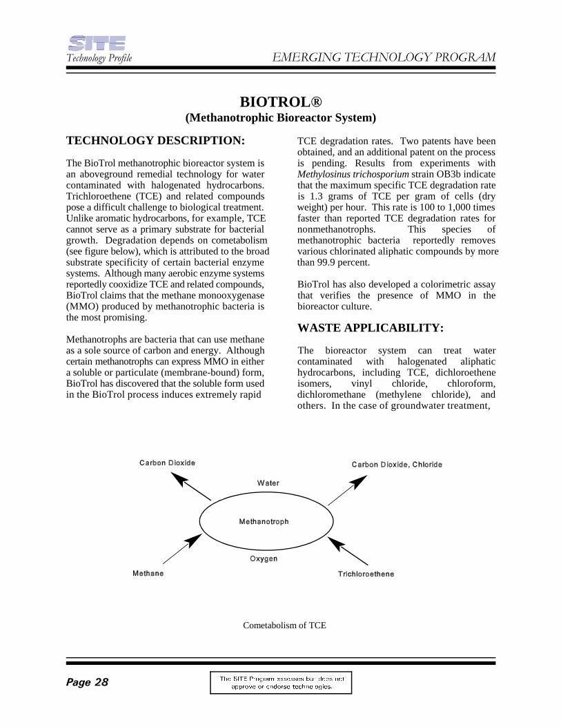
Cometabolism of TCE
BIOTROL®(Methanotrophic Bioreactor System)
TECHNOLOGY DESCRIPTION: TCE degradation rates. Two patents have been
The BioTrol methanotrophic bioreactor system is is pending. Results from experiments withan aboveground remedial technology for water Methylosinus trichosporium strain OB3b indicatecontaminated with halogenated hydrocarbons. that the maximum specific TCE degradation rateTrichloroethene (TCE) and related compounds is 1.3 grams of TCE per gram of cells (drypose a difficult challenge to biological treatment. weight) per hour. This rate is 100 to 1,000 timesUnlike aromatic hydrocarbons, for example, TCE faster than reported TCE degradation rates forcannot serve as a primary substrate for bacterial nonmethanotrophs. This species ofgrowth. Degradation depends on cometabolism methanotrophic bacteria reportedly removes(see figure below), which is attributed to the broad various chlorinated aliphatic compounds by moresubstrate specificity of certain bacterial enzyme than 99.9 percent.systems. Although many aerobic enzyme systemsreportedly cooxidize TCE and related compounds, BioTrol has also developed a colorimetric assayBioTrol claims that the methane monooxygenase that verifies the presence of MMO in the(MMO) produced by methanotrophic bacteria is bioreactor culture.the most promising.
Methanotrophs are bacteria that can use methaneas a sole source of carbon and energy. Although The bioreactor system can treat watercertain methanotrophs can express MMO in either contaminated with halogenated aliphatica soluble or particulate (membrane-bound) form, hydrocarbons, including TCE, dichloroetheneBioTrol has discovered that the soluble form used isomers, vinyl chloride, chloroform,in the BioTrol process induces extremely rapid dichloromethane (methylene chloride), and
obtained, and an additional patent on the process
WASTE APPLICABILITY:
others. In the case of groundwater treatment,
)HEUXDU\�����&RPSOHWHG�3URMHFW
7KH 6,7( 3URJUDP DVVHVVHV EXW GRHV QRW
DSSURYH RU HQGRUVH WHFKQRORJLHV� 3DJH���
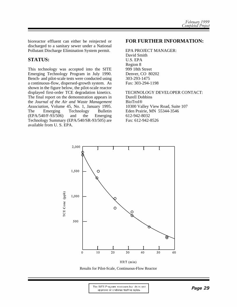
Results for Pilot-Scale, Continuous-Flow Reactor
bioreactor effluent can either be reinjected or FOR FURTHER INFORMATION:discharged to a sanitary sewer under a NationalPollutant Discharge Elimination System permit. EPA PROJECT MANAGER:
STATUS: U.S. EPA
This technology was accepted into the SITE 999 18th StreetEmerging Technology Program in July 1990. Denver, CO 80202Bench- and pilot-scale tests were conducted using 303-293-1475a continuous-flow, dispersed-growth system. As Fax: 303-294-1198shown in the figure below, the pilot-scale reactordisplayed first-order TCE degradation kinetics. TECHNOLOGY DEVELOPER CONTACT:The final report on the demonstration appears in Durell Dobbinsthe Journal of the Air and Waste Management BioTrol®Association, Volume 45, No. 1, January 1995. 10300 Valley View Road, Suite 107The Emerging Technology Bulletin Eden Prairie, MN 55344-3546(EPA/540/F-93/506) and the Emerging 612-942-8032Technology Summary (EPA/540/SR-93/505) are Fax: 612-942-8526available from U. S. EPA.
David Smith
Region 8

7HFKQRORJ\�3URILOH (0(5*,1*�7(&+12/2*<�352*5$0
7KH 6,7( 3URJUDP DVVHVVHV EXW GRHV QRW
DSSURYH RU HQGRUVH WHFKQRORJLHV�3DJH���
Acid Extraction Treatment System (AETS) Process
CENTER FOR HAZARDOUS MATERIALS RESEARCH(Acid Extraction Treatment System)
TECHNOLOGY DESCRIPTION: fertilizer to neutralize any residual acid. No
The acid extraction treatment system (AETS) useshydrochloric acid to extract heavy metal WASTE APPLICABILITY:contaminants from soils. Following treatment, theclean soil may be returned to the site or used as The main application of AETS is extraction offill. heavy metals from soils. The system has been
A simplified block flow diagram of the AETS is more of the following: arsenic, cadmium,shown below. First, soils are screened to remove chromium, copper, lead, nickel, and zinc. Thecoarse solids. These solids, typically greater than treatment capacity is expected to range up to 304 millimeters in size, are relatively clean and tons per hour. AETS can treat all soil fractions,require at most a simple rinse with water or including fines. detergent to remove smaller attached particles.
After coarse particle removal, the remaining soil the cleaned soil, which is suitable for fill or foris scrubbed in an attrition scrubber to break up return to the site, and the heavy metal concentrate.agglomerates and cleanse surfaces. Hydrochloric Depending on the concentration of heavy metals,acid is then introduced into the soil in the the mixtures of heavy metals found at the site, andextraction unit. The residence time in the unit the presence of other compounds (calcium,varies depending on the soil type, contaminants, sodium) with the metals, heavy metals may beand contaminant concentrations, but generally reclaimed from the concentrate.ranges between 10 and 40 minutes. The soil-extractant mixture is continuously pumped out of STATUS:the mixing tank, and the soil and extractant areseparated using hydrocyclones. Under the Emerging Technology Program,
When extraction is complete, the solids are conducted to develop the AETS technology. Thetransferred to the rinse system. The soils are bench-scale pilot system was constructed torinsed with water to remove entrained acid and process between 20 and 100 kilograms of soil permetals. The extraction solution and rinse waters hour. Five soils were tested, including an EPAare regenerated using a proprietary technology synthetic soil matrix (SSM) and soils from fourthat removes the metals and reforms the acid. The Superfund sites, including NL Industries inheavy metals are concentrated in a form Pedricktown, New Jersey; King of Prussia site inpotentially suitable for recovery. During the final Winslow Township, New Jersey; a smelter site instep, the soils are mixed with lime and Butte, Montana; and Palmerton Zinc site in
wastewater streams are generated by the process.
tested using a variety of soils containing one or
The major residuals from AETS treatment include
laboratory-scale and bench-scale tests were
)HEUXDU\�����&RPSOHWHG�3URMHFW
7KH 6,7( 3URJUDP DVVHVVHV EXW GRHV QRW
DSSURYH RU HQGRUVH WHFKQRORJLHV� 3DJH���
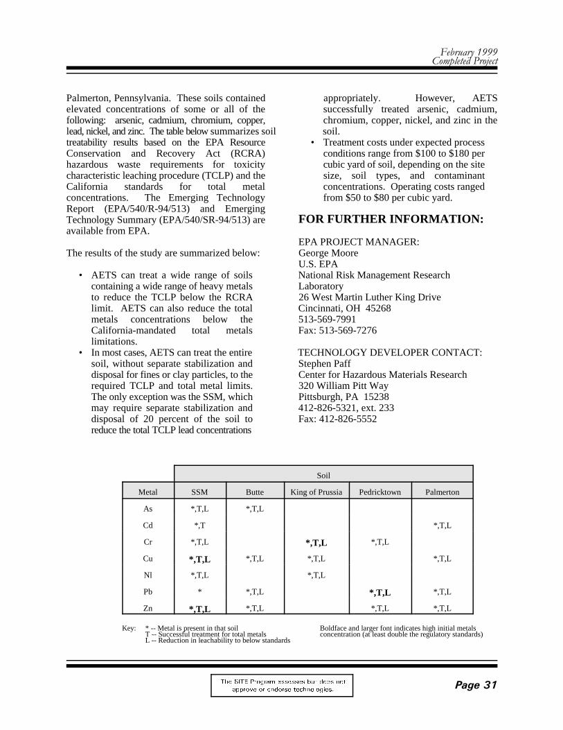
Soil
Metal SSM Butte King of Prussia Pedricktown Palmerton
As *,T,L *,T,L
Cd *,T *,T,L
Cr *,T,L *,T,L *,T,L
Cu *,T,L *,T,L *,T,L *,T,L
Nl *,T,L *,T,L
Pb * *,T,L *,T,L *,T,L
Zn *,T,L *,T,L *,T,L *,T,L
Key: * -- Metal is present in that soil Boldface and larger font indicates high initial metalsT -- Successful treatment for total metals concentration (at least double the regulatory standards)L -- Reduction in leachability to below standards
Palmerton, Pennsylvania. These soils contained appropriately. However, AETSelevated concentrations of some or all of the successfully treated arsenic, cadmium,following: arsenic, cadmium, chromium, copper, chromium, copper, nickel, and zinc in thelead, nickel, and zinc. The table below summarizes soil soil.treatability results based on the EPA Resource • Treatment costs under expected processConservation and Recovery Act (RCRA) conditions range from $100 to $180 perhazardous waste requirements for toxicity cubic yard of soil, depending on the sitecharacteristic leaching procedure (TCLP) and the size, soil types, and contaminantCalifornia standards for total metal concentrations. Operating costs rangedconcentrations. The Emerging Technology from $50 to $80 per cubic yard.Report (EPA/540/R-94/513) and EmergingTechnology Summary (EPA/540/SR-94/513) are FOR FURTHER INFORMATION:available from EPA.
The results of the study are summarized below: George Moore
• AETS can treat a wide range of soils National Risk Management Researchcontaining a wide range of heavy metals Laboratoryto reduce the TCLP below the RCRA 26 West Martin Luther King Drivelimit. AETS can also reduce the total Cincinnati, OH 45268metals concentrations below the 513-569-7991California-mandated total metals Fax: 513-569-7276limitations.
• In most cases, AETS can treat the entire TECHNOLOGY DEVELOPER CONTACT:soil, without separate stabilization and Stephen Paffdisposal for fines or clay particles, to the Center for Hazardous Materials Researchrequired TCLP and total metal limits. 320 William Pitt WayThe only exception was the SSM, which Pittsburgh, PA 15238may require separate stabilization and 412-826-5321, ext. 233disposal of 20 percent of the soil to Fax: 412-826-5552reduce the total TCLP lead concentrations
EPA PROJECT MANAGER:
U.S. EPA

7HFKQRORJ\�3URILOH (0(5*,1*�7(&+12/2*<�352*5$0
7KH 6,7( 3URJUDP DVVHVVHV EXW GRHV QRW
DSSURYH RU HQGRUVH WHFKQRORJLHV�3DJH���
Organics Destruction and Metals Stabilization
CENTER FOR HAZARDOUS MATERIALS RESEARCH(Organics Destruction and Metals Stabilization)
TECHNOLOGY DESCRIPTION: hydrocarbons also produce hydrochloric acid gas.
This technology is designed to destroy hazardous The hydrogen sulfide is oxidized in aorganics in soils while simultaneously stabilizing conventional acid gas treating unit (such as ARImetals and metal ions (see figure below). The Technologies LO-CAT™), recovering the sulfurtechnology causes contaminated liquids, soils, and for reuse.sludges to react with elemental sulfur at elevatedtemperatures. All organic compounds react with In addition to destroying organic compounds, thesulfur. Hydrocarbons are converted to an inert technology converts heavy metals to sulfides,carbon-sulfur powdered residue and hydrogen which are rendered less leachable. If required,sul f ide gas; t reated chlor inated the sulfides can be further stabilized before
These acid gases are recovered from the off-gases.

)HEUXDU\�����&RPSOHWHG�3URMHFW
7KH 6,7( 3URJUDP DVVHVVHV EXW GRHV QRW
DSSURYH RU HQGRUVH WHFKQRORJLHV� 3DJH���
disposal. Thus, heavy metals can be stabilized in The current tests are providing a more detailedthe same process step as the organics destruction. definition of the process limits, metalThe technology's main process components concentrations, and soil types required forconsist of the following: stabilization of various heavy metals to meet the
• A prereaction mixer where the solid and process enhancements are being evaluated toreagent are mixed expand the range of applicability.
• An indirectly heated, enclosed reactorthat includes a preheater section to drive WASTE APPLICABILITY:off water, and two integrated reactorsections to react liquid sulfur with the The technology is applicable to soils andsolids and further react desorbed organic sediments contaminated with both organics andcompounds with vapor-phase sulfur heavy metals.
• An acid gas treatment system thatremoves the acid gases and recovers STATUS:sulfur by oxidizing the hydrogen sulfide
• A treated solids processing unit that This technology was accepted into the SITErecovers excess reagent and prepares the Emerging Technology Program in January 1993.treated product to comply with on-site Bench-scale testing in batch reactors wasdisposal requirements completed in 1993. The pilot-scale program was
Initial pilot-scale testing of the technology has obtaining process data in a continuous unit. Thedemonstrated that organic contaminants can be program was completed in 1995 and the Emergingdestroyed in the vapor phase with elemental Technology Report will be available in 1997.sulfur. Tetrachloroethene, trichloroethene, andpolychlorinated biphenyls were among the FOR FURTHER INFORMATION:organic compounds destroyed.
Batch treatability tests of contaminated soil Randy Parkermixtures have demonstrated organics destruction U.S. EPAand immobilization of various heavy metals. National Risk Management ResearchImmobilization of heavy metals is determined by Laboratorythe concentration of the metals in leachate 26 West Martin Luther King Drivecompared to EPA toxicity characteristic leaching Cincinnati, OH 45268procedure (TCLP) regulatory limits. Following 513-569-7271treatment, cadmium, copper, lead, nickel, and zinc Fax: 513-569-7571were significantly reduced compared to TCLPvalues. In treatability tests with approximately TECHNOLOGY DEVELOPER CONTACT:700 parts per million of Aroclor 1260, destruction Stephen Pafflevels of 99.0 to 99.95 percent were achieved. Center for Hazardous Materials ResearchDestruction of a pesticide, malathion, was also 320 William Pitt Waydemonstrated. The process was also demonstrated Pittsburgh, PA 15238to be effective on soil from manufactured gas 412-826-5321, ext. 233plants, containing a wide range of polynuclear Fax: 412-826-5552aromatics.
limits specified by TCLP. In addition, several
directed at integrating the process concepts and
EPA PROJECT MANAGER:

7HFKQRORJ\�3URILOH (0(5*,1*�7(&+12/2*<�352*5$0
7KH 6,7( 3URJUDP DVVHVVHV EXW GRHV QRW
DSSURYH RU HQGRUVH WHFKQRORJLHV�3DJH���
Metal Leaching and Bioremediation Process
COGNIS, INC.(Biological/Chemical Treatment)
TECHNOLOGY DESCRIPTION: The final treatment products are a recovered metal
The COGNIS, Inc. biological/chemical treatment and clean soil. Contaminated soil is first exposedis a two-stage process that treats soils, sediments, to a leachant solution and classified by particleand other media contaminated with metals and size (see figure below). Size classification allowsorganics. Metals are first removed from the oversized rock, gravel, and sand to be quicklycontaminated matrix by a chemical leaching cleaned and separated from the sediment finesprocess. Organics are then removed by (such as silt, clay, and humus), which requirebioremediation. longer leaching times. Typically, organic
Although metals removal usually occurs in thefirst stage, bioremediation may be performed first After dissolution of the metal compounds, metalif organic contamination levels are found to ions such as zinc, lead, and cadmium are removedinhibit the metals extraction process. from the aqueous leachate by liquid ion exchange,Bioremediation is more effective if the metal resin ion exchange, or reduction. At this point,concentrations in the soil are sufficiently low so the aqueous leaching solution is freed of metalsas not to inhibit microbial activity. However, and can be reused to leach additional metal fromeven in the presence of inhibitory metal the contaminated soil. If an extraction agent isconcentrations, a microbe population may be used, it is later stripped of the bound metal andenriched to perform the necessary bioremediation. the agent is fully regenerated and recycled.
Soil handling requirements for both stages are concentrated form as solid metal or a metal salt.similar, so unit operations are fully reversible. The method of metals recovery
or metal salt, biodegraded organic compounds,
pollutants are also attached to the fines.
Heavy metals are recovered in a saleable,

)HEUXDU\�����&RPSOHWHG�3URMHFW
7KH 6,7( 3URJUDP DVVHVVHV EXW GRHV QRW
DSSURYH RU HQGRUVH WHFKQRORJLHV� 3DJH���
depends on the metals present and their STATUS:concentrations.
After metals extraction is complete, the "mud" SITE Emerging Technology Program in Augustslurry settles and is neutralized. Liquids are 1992. Bench- and pilot-scale testing of thereturned to the classifier, and the partially treated bioremediation process is complete. A full-scalesoil is transferred to a slurry bioreactor, a field test of the metals extraction process wasslurry-phase treatment lagoon, or a closed land completed under the Demonstration Program. Fortreatment cell for bioremediation. The soil and further information on the full-scale process, referthe residual leachate solution are treated to to the profile in the Demonstration Programmaximize contaminant biodegradation. Nutrients section.are added to support microbial growth, and themost readily biodegradable organic compounds This remediation process is no longer availableare aerobically degraded. through COGNIS, Inc. For further information
Bench-scale tests indicate that this process can Manager.remediate a variety of heavy metals and organicpollutants. The combined process is less FOR FURTHER INFORMATION:expensive than separate metals removal andorganic remediation. EPA PROJECT MANAGER:
WASTE APPLICABILITY: U.S. EPA
This remediation process is intended to treat Laboratorycombined-waste soils contaminated by heavy 26 West Martin Luther King Drivemetals and organic compounds. The process can Cincinnati, OH 45208treat contaminants including lead, cadmium, zinc, 513-569-7149and copper, as well as petroleum hydrocarbons Fax: 513-569-7105and polynuclear aromatic hydrocarbons that aresubject to aerobic microbial degradation. Thecombined process can also be modified to extractmercury and other metals, and to degrade morerecalcitrant halogenated hydrocarbons.
This remediation process was accepted into the
about the process, contact the EPA Project
Steven Rock
National Risk Management Research

7HFKQRORJ\�3URILOH (0(5*,1*�7(&+12/2*<�352*5$0
7KH 6,7( 3URJUDP DVVHVVHV EXW GRHV QRW
DSSURYH RU HQGRUVH WHFKQRORJLHV�3DJH���
Smelting Lead-Containing Waste Process
CONCURRENT TECHNOLOGIES(Formerly Center for Hazardous Materials Research)
(Smelting Lead-Containing Waste)
TECHNOLOGY DESCRIPTION: sized lead-containing waste. These furnaces
Secondary lead smelting is a proven technology intermittently to remove slag, which is transportedthat reclaims lead from lead-acid battery waste offsite for disposal. The reverberatory and blastsites. The Concurrent Technologies and Exide furnace combination at Exide can reclaim leadCorporation (Exide) have demonstrated the use of from batteries and waste with greater thansecondary lead smelting to reclaim usable lead 99 percent efficiency.from various types of waste materials fromSuperfund and other lead-containing sites. WASTE APPLICABILITY:Reclamation of lead is based on existing leadsmelting procedures and basic pyrometallurgy. The process has been demonstrated to reclaim
The figure below is a generalized process flow rubber battery case material, lead dross, iron shotdiagram. Waste material is first excavated from abrasive blasting material, and wood fromSuperfund sites or collected from other sources. demolition of houses coated with lead paint. TheThe waste is then preprocessed to reduce particle technology is applicable to solid wastessize and to remove rocks, soil, and other debris. containing more than 2 percent lead, provided thatNext, the waste is transported to the smelter. they do not contain excessive amounts of calcium,
At the smelter, waste is fed to reverberatory or Explosive and flammable liquids cannot beblast furnaces, depending on particle size or lead processed in the furnace. As tested, thiscontent. The two reverberatory furnaces normally technology is not applicable to soil remediation.treat lead from waste lead-acid batteries, as wellas other lead-containing material. The furnaces STATUS:are periodically tapped to remove slag, whichcontains 60 to 70 percent lead, and a soft pure This technology was accepted into the SITElead product. Emerging Technology Program in July 1991.
The two blast furnaces treat slag generated from February 1993. the reverberatory furnaces, as well as larger-
aretapped continuously for lead and tapped
lead from a variety of solid materials, including
silica, aluminum, or other similar constituents.
Field work for the project was completed in

)HEUXDU\�����&RPSOHWHG�3URMHFW
7KH 6,7( 3URJUDP DVVHVVHV EXW GRHV QRW
DSSURYH RU HQGRUVH WHFKQRORJLHV� 3DJH���
Source of Material/Type of Material Tested % Lead Economical* Test Results
Tonolli Superfund site (PA)/Battery cases
3 to 7 Yes Lead can be reclaimed in secondary lead smelter; incorporated into regular blast furnace feed stock.
Hebalka Superfund site (PA)/Battery cases
10 Yes Lead can be reclaimed in secondary lead smelter; reduced in size and incorporated into regularreverberatory furnace feed stock.
Pedricktown Superfund site (NJ)/Battery cases; lead dross, residue, anddebris
45 Yes Lead can be reclaimed in secondary lead smelter;screened and incorporated into regularreverberatory and blast furnace feed stocks.
Laurel House Women's Shelter (PA)/Demolition material contaminatedwith lead-based paint.
1 No Lead can be reclaimed in secondary lead smelter; however, the cost of processing the material wasestimated to be very high.
PennDOT/Abrasive bridge blasting material
3 to 5 Yes Lead can be reclaimed in secondary lead smelter; incorporated into regular blast furnace feed stock.
* Compared to stabilization or landfilling
Results from Field Tests of the Smelting Lead-Containing Waste Technology
The process was tested at three Superfund sites. smelting is an economical method of reclaimingMaterials obtained from two additional sites were lead from lead-containing waste materialalso used for these tests. Results from the collected at Superfund sites and other sources.Emerging Technology Program, presented in thetable below, show that the process is applicable to FOR FURTHER INFORMATION:waste materials at each site and economicallyfeasible for all but demolition material. The EPA PROJECT MANAGER:Emerg ing Technology Bul let in Laurel Staley(EPA/540/F-94/510), the Emerging U.S. EPATechnology Summary (EPA/540/SR-95/504), and National Risk Management Researchthe Emerging Technology Report (EPA/540/R- Laboratory95/504) are available from EPA. An article about 26 West Martin Luther King Drivethe technology was also published by the Journal Cincinnati, OH 45268of Hazardous Materials in February 1995. 513-569-7863
Specific technical problems encountered included(1) loss of furnace production due to material TECHNOLOGY DEVELOPER CONTACT:buildup within the furnaces, (2) breakdowns in the Brian Bosilovichfeed system due to mechanical overloads, and (3) Concurrent Technologies Corporationincreased oxygen demands inside the furnaces. 320 William Pitt WayAll of these problems were solved by adjusting Pittsburgh, PA 15238material feed rates or furnace parameters. 412-826-5321, ext. 230Based on these tests, Concurrent Fax: 412-826-5552Technologies has concluded that secondary lead
Fax: 513-569-7105

7HFKQRORJ\�3URILOH (0(5*,1*�7(&+12/2*<�352*5$0
7KH 6,7( 3URJUDP DVVHVVHV EXW GRHV QRW
DSSURYH RU HQGRUVH WHFKQRORJLHV�3DJH���
Reductive Photo-Dechlorination (RPD) Treatment
ENERGIA, INC.(Reductive Photo-Dechlorination Treatment)
TECHNOLOGY DESCRIPTION: Chlorinated contaminants adsorbed onto activated
The Reductive Photo-Dechlorination (RPD) heated to induce vaporization. The ensuingtreatment uses ultraviolet (UV) light in a reducing vapors are then fed into the photo-thermalatmosphere and at moderate temperatures to treat chamber.waste streams containing chlorinatedhydrocarbons (CIHC). Because CIHCs are The photo-thermal chamber is the heart of thedestroyed in a reducing environment, the only RPD process because all reactions central to theproducts are hydrocarbons and hydrogen chloride process occur in this chamber. Saturated, olefinic,(HCl). or aromatic chlorocarbons with one or more
The RPD process is depicted in the figure below. heat, and a reducing atmosphere, such asThe process consists of five main units: (1) hydrogen gas or methane. According toinput/mixer (2) photo-thermal chamber (3) HCl ENERGIA, Inc., carbon-chlorine bonds arescrubber (4) separator and (5) products storage broken, resulting in chain-propagatingand recycling. Chlorinated wastes may be hydrocarbon reactions. Chlorine atoms areintroduced into the process in one of three ways: eventually stabilized as HCl, which is easilyvapor, liquid, or bound to an adsorbent, such as removed in a scrubber. Hydrocarbons may holdactivated carbon. their original structures, rearrange, cleave, couple,
Air laden with chlorocarbon vapors is first passed Hydrocarbons produced from the dechlorinationthrough a condenser, which removes chlorinated of wastes include ethane, acetylene, ethene, andmaterials as liquids. Chlorocarbon liquids are fed methane. Valuable hydrocarbon products can beinto a vaporizer, mixed with a reducing gas, and stored, sold, or recycled as auxiliary fuel to heatpassed into the photo-thermal chamber. the photo-thermal chamber.
carbon are purged with reducing gas and mildly
carbon-chlorine bonds are exposed to UV light,
or go through additional hydrogenation.

)HEUXDU\�����&RPSOHWHG�3URMHFW
7KH 6,7( 3URJUDP DVVHVVHV EXW GRHV QRW
DSSURYH RU HQGRUVH WHFKQRORJLHV� 3DJH���
WASTE APPLICABILITY: dechlorination were demonstrated with high
The RPD process is designed specifically to treat products, ethane and methane. Similar favorablevolatile chlorinated wastes in the liquid, gaseous, results were obtained for other saturated andor adsorbed states. The RPD process was tested unsaturated chlorocarbons treated by the RPDon methyl chloride, dichloromethane (DCM), process. chloroform, carbon tetrachloride, trichloroethane(TCA), dichloroethene (PCE), and trichloroethene Results of a cost analysis based on experimental(TCE). data indicate that the RPD process is extremely
Field applications include treatment of organic treating TCE concentrations of 1,000 ppm andwastes discharged from soil vapor extraction 10,000 ppm is $1.10 and $0.25 per pound treated,operations, vented from industrial hoods and respectively. The cost per 1,000 cubic feet ofstacks, and adsorbed on activated carbon. The contaminated stream with 1,000 ppm is $0.38 andprocess can be used to (1) treat gas streams $0.88, respectively.containing chlorinated hydrocarbons, and (2)pretreat gas streams entering catalytic oxidation All technical data have been gathered andsystems by reducing chlorine content and optimization has been completed. Design andprotecting the catalyst against poisoning. assembly of a pilot-scale prototype are underway.
In comparison to other photo-thermal processes 1999. The developer is seeking appropriate sites(such as reductive photo-thermal oxidation for field demonstration. After successful[RPTO] and photo-thermal oxidation [PTO]), the demonstration, the RPD process will be ready forRPD process is mostly applicable to streams full-scale commercialization.without air and very high concentrations ofcontaminants (bulk down to greater than 1 FOR FURTHER INFORMATION:percent). At very low concentrations (parts permillion) and in the presence of air, the other EPA PROJECT MANAGER:photo-thermal processes may more cos- effective. Michelle Simon
STATUS: National Risk Management Research
Bench-scale experiments were conducted on 26 West Martin Luther King Driveseveral contaminants (such as DCM, DCE, TCA, Cincinnati, OH 45268and TCE). Measurements of concentrations of 513-569-7469parent compounds and products as a function of Fax: 513-569-7676residence time were obtained at several testconditions. From these measurements, conversion TECHNOLOGY DEVELOPER CONTACT:and dechlorination efficiencies were determined Moshe Lavidat optimal operating conditions. ENERGIA, Inc.
Experimental results on a representative Princeton, NJ 08542-470chlorocarbon contaminant (TCA) are available in 609-799-7970the Emerging Technology Bulletin (EPA/540/F- Fax: 609-799-031294/508). Greater than 99 percent conversion and
selectivity towards two saleable hydrocarbon
cost competitive. For example, the cost of
The field demonstration may take place during
U.S. EPA
Laboratory
P.O. Box 470

7HFKQRORJ\�3URILOH (0(5*,1*�7(&+12/2*<�352*5$0
7KH 6,7( 3URJUDP DVVHVVHV EXW GRHV QRW
DSSURYH RU HQGRUVH WHFKQRORJLHV�3DJH���
ENERGY AND ENVIRONMENTALRESEARCH CORPORATION
(Hybrid Fluidized Bed System)
TECHNOLOGY DESCRIPTION: fluidized bed afterburner. The afterburner
The Hybrid Fluidized Bed (HFB) system treats incinerate the organic compounds that escape thecontaminated solids and sludges by incinerating spouted bed, resulting in a destruction andorganic compounds and extracting and removal efficiency of greater than 99.99 percent.detoxifying volatile metals. The system consists The afterburner also contains bed materials thatof three stages: a spouted bed, a fluidized absorb metal vapors, capture fine particles, andafterburner, and a high-temperature particulate promote formation of insoluble metal silicates.soil extraction system. The bed materials are typically made of silica-
First, the spouted bed rapidly heats solids andsludges to allow extraction of volatile organic and In the third stage, the high-temperature particulateinorganic compounds. The spouted bed retains soil extraction system removes clean processedlarger soil clumps until they are reduced in size soil from the effluent gas stream with one or twobut allows fine material to pass through quickly. hot cyclones. Clean soil is extracted hot toThis segregation process is beneficial because prevent unreacted volatile metal species fromorganic contaminants in fine particles vaporize condensing in the soil. Off-gases are thenrapidly. The decontamination time for large quenched and passed through a conventionalparticles is longer due to heat and mass transfer baghouse to capture the condensed metal vapors.limitations.
The central spouting region is operated with an major operational difficulties for soil cleanupinlet gas velocity of greater than 150 feet per devices. The HFB system uses a speciallysecond. This velocity creates an abrasion and designed auger feed system. Solids and sludgesgrinding action, rapidly reducing the size of the are dropped through a lock hopper system into anfeed materials through attrition. The spouted bed auger shredder, which is a rugged, low-operates between 1,500 and 1,700 (F under revolutions-per-minute, feeding-grinding device.oxidizing conditions. Standard augers are simple and reliable, but often
Organic vapors, volatile metals, and fine soil compression in the auger. In the HFB system, theparticles are carried from the spouted bed through auger shredder is close-coupled to the spoutedan open-hole type distributor, which forms the bed to reduce compression and clump formationbottom of the second stage, the during feeding. The close-couple
provides sufficient retention time and mixing to
supported bauxite, kaolinite, or lime.
Generally, material handling problems create
they are susceptible to clogging from feed

)HEUXDU\�����&RPSOHWHG�3URMHFW
7KH 6,7( 3URJUDP DVVHVVHV EXW GRHV QRW
DSSURYH RU HQGRUVH WHFKQRORJLHV� 3DJH���
arrangement locates the tip of the auger screw FOR FURTHER INFORMATION:several inches from the internal surface of thespouted bed, preventing the formation of soil EPA PROJECT MANAGER:plugs. Teri Richardson
WASTE APPLICABILITY: National Risk Management Research
This technology is applicable to soils and sludges 26 West Martin Luther King Drivecontaminated with organic and volatile inorganic Cincinnati, OH 45268contaminants. Nonvolatile inorganics are not 513-569-7949affected. Fax: 513-569-7105
STATUS: TECHNOLOGY DEVELOPER CONTACT:
This technology was accepted into the SITE Energy and Environmental ResearchEmerging Technology Program in January 1990. CorporationDesign and construction of the commercial 18 Mason Streetprototype HFB system and a limited shakedown Irvine, CA 92718are complete. The Emerging Technology Bulletin 714-859-8851(EPA/540/F-93/508) is available from EPA. Fax: 714-859-3194
U.S. EPA
Laboratory
Richard Koppang

7HFKQRORJ\�3URILOH (0(5*,1*�7(&+12/2*<�352*5$0
7KH 6,7( 3URJUDP DVVHVVHV EXW GRHV QRW
DSSURYH RU HQGRUVH WHFKQRORJLHV�3DJH���
Example Application of RFS Equipment
ENERGY AND ENVIRONMENTALRESEARCH CORPORATION
(Reactor Filter System)
TECHNOLOGY DESCRIPTION: • First, solids are treated with a primary
The Energy and Environmental Research fluidized bed, or other system designedCorporation (EER) Reactor Filter System (RFS) for thermal treatment.technology is designed to control gaseous and • Next, a low-cost, aluminosilicateentrained particulate matter emissions from the sorbent, such as kaolinite, is injectedprimary thermal treatment of sludges, soils, and into the flue gases at temperatures nearsediments. Most Superfund sites are 1,300 (C (2,370 (F). The sorbent reactscontaminated with toxic organic chemicals and with volatile metal species such as lead,metals. Currently available thermal treatment cadmium, and arsenic in the gas stream;systems for detoxifying these materials release the metals chemically adsorb onto theproducts of incomplete combustion (PIC) and surfaces of the sorbent particles. Thisvolatile toxic metals. In addition, the large air adsorbtion forms insoluble,pollution control devices (APCD) often required nonleachable alumino-silicate complexesto control PICs and metals are generally not similar to cementitious species.suitable for transport to remote Superfund sites. • Finally, fabric filtration, operating atEER designed the RFS to avoid some of these temperatures up to 1,000 (C (1,830 (F)logistical problems. The RFS uses a fabric filter provides additional residence time forinstalled immediately downstream of the thermal the sorbent/metalreaction, producingtreatment process; the filter controls toxic metals, nonleachable by-products. This stepparticulates, and unburned organic species. The also provides additional time for theRFS involves the following three steps: destruction of organic compounds
thermal process, such as a rotary kiln,
associated with particulate matter,reducing ash toxicity.
)HEUXDU\�����&RPSOHWHG�3URMHFW
7KH 6,7( 3URJUDP DVVHVVHV EXW GRHV QRW
DSSURYH RU HQGRUVH WHFKQRORJLHV� 3DJH���
Because of the established link between PIC WASTE APPLICABILITY:formation and gas-particle chemistry, this processcan virtually eliminate potential polychlorinated The RFS is designed to remove entraineddioxin formation. particulates, volatile toxic metals, and condensed-
The RFS may improve the performance of to 1,000 (C) gas streams generated from theexisting thermal treatment systems for Superfund thermal treatment of contaminated soils, sludges,wastes containing metals and organics. During and sediments. Many conventional treatments canincineration, hazardous organics are often be combined with the RFS technology. Processattached to the particulate matter that escapes residuals will consist of nonleachable particulatesburning in the primary zone. The RFS provides that are essentially free of organic compounds,sufficient residence time at sufficiently high thus reducing toxicity, handling risks, and landfilltemperatures to destroy such organics. Also, by disposal.increasing gas-solid contact parameters, thesystem can decrease metal emissions by STATUS:preventing the release of metals in vapors orretained on entrained particles. The RFS was accepted into the Emerging
The figure on the previous page shows the RFS pilot-scale process through a series of bench-scaleinstalled immediately downstream of the primary screening studies, which were completed inthermal treatment zone at EER's Spouted Bed September 1994. The screening studies guidedCombustion Facility. Because the spouted bed the sorbent selection and operating conditions forgenerates a highly particulate-laden gas stream, a the pilot-scale demonstration. The tests werehigh-temperature cyclone is used to remove completed in 1996; the final report will becoarse particulate matter upstream of the RFS. available from the National Technical InformationSorbent is injected into the flue gas upstream of Service.the high temperature fabric filter. A conventionalbaghouse was available for comparison with RFS FOR FURTHER INFORMATION:performance during the demonstration. However,the baghouse is not needed in typical RFS EPA PROJECT MANAGER:applications because the high-temperature Steven Rockfiltration medium has shown similar performance U.S. EPAto conventional fabric filtration media. National Risk Management Research
phase organics present in high-temperature (800
Technology Program in 1993. EER developed the
Laboratory26 West Martin Luther King DriveCincinnati, OH 45268513-569-7149Fax: 513-569-7105
TECHNOLOGY DEVELOPER CONTACT:Neil WidmerEnergy and Environmental Research Corporation18 Mason StreetIrvine, CA 92718714-859-8851Fax: 714-859-3194

7HFKQRORJ\�3URILOH (0(5*,1*�7(&+12/2*<�352*5$0
7KH 6,7( 3URJUDP DVVHVVHV EXW GRHV QRW
DSSURYH RU HQGRUVH WHFKQRORJLHV�3DJH���
Fungal Degradation of Five PAHs in Soil Over A 59-Day Period
ENVIRONMENTAL BIOTECHNOLOGIES, INC.(Fungal Degradation Process)
TECHNOLOGY DESCRIPTION: Some states have a soil treatment standard of 100
Polycyclic aromatic hydrocarbons (PAH) are treatment process was able to reach this cleanuptypical pollutants at creosote wood treatment sites standard within a 5- to 6-week treatment periodand at manufacturing gas plants (MGP). Media for one PAH-contaminated soil, as shown in thecontaminated with these compounds are figure on the next page.considered hazardous due to the potentialcarcinogenic effects of specific PAHs. WASTE APPLICABILITY:
Environmental BioTechnologies, Inc. (EBT), One intended environmental application for thisinvestigated the bioremediation of contaminants technology is the treatment of soil and sedimentassociated with former MGP sites in a program contaminated with coal tar wastes from formercosponsored by the Electric Power Research MGP sites. Soils at these sites are contaminatedInstitute and the U. S. EPA. Initially, EBT with PAHs and are difficult to cost-effectivelyscreened over 500 fungal cultures (mostly brown remediate. EBT’s fungal soil treatment process isand white rot fungi) for their ability to degrade projected to cost $66 to $80 per ton, which isPAHs and other organic pollutants. A group of 30 more cost-effective than other technicalcultures were more intensely examined and approaches such as coburning in utility burners,several cultures were optimized for use in a soil thermal desorption, and incineration.composting process.
EBT conducted bench-scale treatability studies toassess the feasibility of PAH degradation in soil EBT was accepted into the SITE Emergingusing a fungal-augmented system designed to Technology Program in 1993 and beganenhance natural biological metabolic processes. laboratory studies in 1994. The project wasResults of one study are shown in the figure completed in 1996. The overall project objectivesbelow. Concentrations of 10 PAHs were were to (1) identify fungal and bacterial culturesdetermined over a 59-day treatment period. that efficiently degrade coal tar
parts per million for total PAHs. EBT’s fungal
STATUS:

)HEUXDU\�����&RPSOHWHG�3URMHFW
7KH 6,7( 3URJUDP DVVHVVHV EXW GRHV QRW
DSSURYH RU HQGRUVH WHFKQRORJLHV� 3DJH���
Degradation of Total PAHs In Soil
wastes, and (2) develop and demonstrate a pilot- EBT has also conducted a bench-scale treatabilityscale process that can be commercialized for study for a company in France to determine theutility industry applications. feasibility of fungal PAH degradation in MGP
EBT initially worked with PAH-spiked water and biodegradation in the fungal-augmented systemsoils. EBT then tested, under optimized for all of the measured individual PAHconditions, selected soil cultures from several compounds in the 80-day treatment period,MGP sites identified by New England Electric compared with the natural, unamended system.Services, a utility company sponsor. Testingidentified several possibly superior fungal EBT is also currently conducting a 10-ton soilcultures capable of degrading PAHs. These PAH field project to demonstrate that the fungalcultures exhibited degradative preferences for degradation process can be scaled up and used ineither lower molecular weight or higher molecular commercial applications.weight PAHs, suggesting a consortia as a possiblebest approach. These cultures were then FOR FURTHER INFORMATION:examined in nutrient-supplemented systems todetermine optimal PAH degradation rates. EPA PROJECT MANAGER:
A bench-scale composter system was used to U.S. EPAdetermine optimal moisture content, soil National Risk Management Researchamendment requirements, and inoculation Laboratoryprocedures for accelerating PAH degradation. 26 West Martin Luther King DriveDuring the second year, small (less than 1 cubic Cincinnati, OH 45268yard) plots of MGP-site soil were used to test the 513-569-7856optimized process in laboratory studies before a Fax: 513-569-7105field demonstration is conducted. Results fromthe evaluation was published by U. S. EPA in TECHNOLOGY DEVELOPER CONTACT:1997. Based on its performance during the Douglas MunneckeEmerging Technology Program evaluation, the Environmental BioTechnologies, Inc.microbial composting process has been invited to 969C Industrial Roadparticipate in the SITE Demonstration Program. San Carlos, CA 94070
soil. Results demonstrated an increased rate of
Ronald Lewis
415-596-1020Fax: 415-596-1016E-mail: [email protected]

7HFKQRORJ\�3URILOH (0(5*,1*�7(&+12/2*<�352*5$0
7KH 6,7( 3URJUDP DVVHVVHV EXW GRHV QRW
DSSURYH RU HQGRUVH WHFKQRORJLHV�3DJH���
Electric Furnace Vitrification
FERRO CORPORATION(Waste Vitrification Through Electric Melting)
TECHNOLOGY DESCRIPTION: Commercial electric melters have significantly
Vitrification technology converts contaminated such as boric anhydride (B O ) or lead oxidesoils, sediments, and sludges into oxide glasses, (PbO). Because of its low emission rate and smallchemically rendering them nontoxic and suitable volume of exhaust gases, electric melting is afor landfilling as nonhazardous materials. promising technology for incorporating waste intoSuccessful vitrification of soils, sediments, and a stable glass matrix.sludges requires (1) development of glasscompositions tailored to a specific waste, and WASTE APPLICABILITY:(2) glass melting technology that can convert thewaste and additives into a stable glass without Vitrification stabilizes inorganic componentsproducing toxic emissions. found in hazardous waste. In addition, the high
In an electric melter, glass — an ionic conductor 1,500 (C) decomposes organic compounds in theof relatively high electrical resistivity — stays waste such as anthracene, bis(2-ethylhexylmolten with heating. Such melters process waste phthalate), and pentachlorophenol. Theunder a relatively thick blanket of feed material, decomposition products can easily be removedwhich forms a counterflow scrubber that limits from the low volume of melter off-gas.volatile emissions (see figure below).
reduced the loss of inorganic volatile constituents2 3
temperature involved in glass production (about

)HEUXDU\�����&RPSOHWHG�3URMHFW
7KH 6,7( 3URJUDP DVVHVVHV EXW GRHV QRW
DSSURYH RU HQGRUVH WHFKQRORJLHV� 3DJH���
7&/3 DQDO\WH FRQFHQWUDWLRQ�
SDUWV SHU PLOOLRQ
0HWDO5HPHGLDWLRQ
/LPLW
0HDQ RI *ODVV
5HSOLFDWHV
$V � ������
&G � ������
&U � �����
&X � �����
3E � �����
1L � ������
=Q � �����
STATUS: FOR FURTHER INFORMATION:
Under the Emerging Technology Program, EPA PROJECT MANAGER:synthetic soil matrix IV (SSM-IV) has been Randy Parkerdeveloped and subjected to toxicity characteristic U.S. EPAleaching procedure (TCLP) testing. National Risk Management Research
Ten independent replicates of the preferred 26 West Martin Luther King Drivecomposition produced the following results: Cincinnati, OH 45268
SSM-IV and additives (including sand, soda ash,and other minerals) required to convert SSM-IVto the preferred glass composition have beenprocessed in a laboratory-scale electric melter.Three separate campaigns have produced glass at17 pounds per hour at a fill of 67 percent SSM-IVand 33 percent glass-making additives. TheTCLP mean analyte concentrations were less than10 percent of the remediation limit at a statisticalconfidence of 95 percent. Ferro Corporation's ex-perience indicates that this melting rate wouldproduce an equivalent rate of 1 ton per hour in anelectric melter used to treat wastes at a Superfundsite. The Emerging Technology Bulletin(EPA/540/F-95/503) is available from EPA.
Laboratory
513-569-7271Fax: 513-569-7571
TECHNOLOGY DEVELOPER CONTACT:S.K. MuralidharFerro CorporationCorporate Research7500 East Pleasant Valley RoadIndependence, OH 44131216-641-8580Fax: 216-524-0518

7HFKQRORJ\�3URILOH (0(5*,1*�7(&+12/2*<�352*5$0
7KH 6,7( 3URJUDP DVVHVVHV EXW GRHV QRW
DSSURYH RU HQGRUVH WHFKQRORJLHV�3DJH���
Acoustic Barrier Particulate Separator
GENERAL ATOMICS,NUCLEAR REMEDIATION TECHNOLOGIES DIVISION
(Acoustic Barrier Particulate Separator)
TECHNOLOGY DESCRIPTION: The gas flows past the acoustic source and leaves
The acoustic barrier separates particulates in a gas then passes through another muffler chamberhigh temperature gas flow. The separator and flows through sections where it is allowed toproduces an acoustic waveform directed against cool and any remaining gas-borne particulatethe gas flow, causing particulates to move samples are collected. Finally, the gas is furtheropposite the flow. The particulates drift to the scrubbed or filtered as necessary before it iswall of the separator, where they aggregate with discharged.other particulates and precipitate into a collectionhopper. The acoustic barrier particulate separator The separator can remove the entire range ofdiffers from other separators by combining both particle sizes; it has a removal efficiency ofhigh efficiency and high temperature capabilities. greater than 90 percent for submicron particles
The figure below presents a conceptual design. 99 percent. Due to the large diameter of theHigh temperature inlet gas flows through a separator, the system is not prone to fouling.muffler chamber and an agglomeration segmentbefore entering the separation chamber. In the WASTE APPLICABILITY:separation chamber, particulates stagnate due tothe acoustic force and then drift to the chamber This technology can treat off-gas streams fromwall, where they collect as a dust cake that falls thermal desorption, pyrolysis, and incineration ofinto a collection hopper. The solids are soil, sediment, sludges, other solid wastes, andtransported from the collection hopper by a screw- liquid wastes. The acoustic barrier particulatetype conveyor against a clean purge gas separator is a high-temperature, high-throughputcounterflow. The purge gas cools the solids and process with a high removal efficiency for fineguards against contamination of particulates by dust and fly ash. It is particularly suited forinlet-gas volatiles in the process stream. thermal processes where high temperatures must
the separation chamber through an exit port. The
and an overall removal efficiency of greater than
be maintained to prevent condensation ontoparticulates. Applications include removal of

)HEUXDU\�����&RPSOHWHG�3URMHFW
7KH 6,7( 3URJUDP DVVHVVHV EXW GRHV QRW
DSSURYH RU HQGRUVH WHFKQRORJLHV� 3DJH���
gas-borne solids during thermal treatment of FOR FURTHER INFORMATION:semivolatile organics, such as polychlorinatedbiphenyls, and gas-phase separation of radioactive EPA PROJECT MANAGER:particles from condensible hazardous materials. Ronald Lewis
STATUS: National Risk Management Research
The acoustic barrier particulate separator was 26 West Martin Luther King Driveaccepted into the SITE Emerging Technology Cincinnati, OH 45268Program in 1993. The principal objective of this 513-569-7856project will be to design, construct, and test a Fax: 513-569-7105pilot-scale acoustic barrier particulate separatorthat is suitable for parallel arrangement into larger TECHNOLOGY DEVELOPER CONTACT:systems. The separator will be designed for a Anthony Gattusoflow of 300 cubic feet per minute and will be General Atomicstested using a simulated flue gas composed of Nuclear Remediation Technologies Divisionheated gas and injected dust. MS 2/633
U.S. EPA
Laboratory
P.O. Box 85608San Diego, CA 92186-9784619-455-2910Fax: 619-455-3679

7HFKQRORJ\�3URILOH (0(5*,1*�7(&+12/2*<�352*5$0
7KH 6,7( 3URJUDP DVVHVVHV EXW GRHV QRW
DSSURYH RU HQGRUVH WHFKQRORJLHV�3DJH���
Two-Zone, Plume Interception, In Situ Treatment Strategy
HARDING LAWSON ASSOCIATES(Formerly ABB Environmental Services, Inc.)
(Two-Zone, Plume Interception, In Situ Treatment Strategy)
TECHNOLOGY DESCRIPTION: designed to biologically oxidize the partially
The two-zone, plume interception, in situ as other compounds that were not susceptible totreatment strategy is designed to treat chlorinated the anaerobic treatment phase.and nonchlorinated organic compounds insaturated soils and groundwater using a sequence Anaerobic conditions are produced or enhanced inof anaerobic and aerobic conditions (see figure the first treatment zone by introducing a primarybelow). The in situ anaerobic and aerobic system carbon source, such as lactic acid, and mineralconstitutes a treatment train that biodegrades a nutrients, such as nitrogen and phosphorus. Whenwide assortment of chlorinated and proper anaerobic conditions are attained, the targetnonchlorinated compounds. contaminants are reduced. For example, PCE is
When applying this technology, anaerobic and to dichloroethene (DCE) and vinyl chloride.aerobic conditions are produced in two distinct, Under favorable conditions, this process canhydraulically controlled, saturated soil zones. completely dechlorinate the organics to etheneGroundwater passes through each zone as it is and ethane.recirculated through the treatment area. The firstzone, the anaerobic zone, is designed to partially Aerobic conditions are produced or enhanced indechlorinate highly chlorinated solvents such as the second treatment zone by introducing oxygen,tetrachloroethene (PCE), trichloroethene (TCE), mineral nutrients such as nitrogen andand 1,1,1-trichloroethane with natural biological phosphorus, and possibly an additional carbonprocesses. The second zone, the aerobic zone, is source, such as methane (if an insufficient supply
dechlorinated products from the first zone, as well
dechlorinated to TCE, and TCE is dechlorinated

)HEUXDU\�����&RPSOHWHG�3URMHFW
7KH 6,7( 3URJUDP DVVHVVHV EXW GRHV QRW
DSSURYH RU HQGRUVH WHFKQRORJLHV� 3DJH���
of methane results from the upstream, anaerobic Emerging Technology Bulletin (EPA/540/F-95/510),zone). When proper aerobic conditions are which details the bench-scale testing results, isattained in this zone, partially dechlorinated available from EPA. products and other target compounds from thefirst zone are oxidized. For example, less- A pilot-scale field demonstration system waschlorinated ethenes such as DCE and vinyl installed at an industrial facility in Massachusetts.chloride are cometabolized during the aerobic Pilot-scale testing began in September 1996.microbiological degradation of methane. Results from this testing indicate the following:
The treatment strategy is designed to biologically TCE to DCE, VC, and ethene has beenremediate subsoils by enhancing indigenous accomplished primarily by sulfate-reducingmicroorganism activity. If indigenous bacterial bacteria.populations do not provide the adequate anaerobic & A time lag of about 4 months was requiredor aerobic results, specially adapted cultures can before significant reductive dechlorinationbe introduced to the aquifer. These cultures are occurred. This corresponded to the timeintroduced using media-filled trenches that can and lactic acid dosing required to reduce thesupport added microbial growth. redox to about -100 throughout the
WASTE APPLICABILITY: & Sequential anaerobic-aerobic (Two-Zone)
The two-zone, plume interception, in situ treatment products appear to be a viable and cost-strategy is designed to treat groundwater and effective treatment technology for thesaturated soils containing chlorinated and enhancement of natural reductivenonchlorinated organic compounds. dechlorination processes.
STATUS: FOR FURTHER INFORMATION:
The two-zone, plume interception, in situ EPA PROJECT MANAGER:treatment strategy was accepted into the SITE Ronald LewisEmerging Technology Program in July 1989. U.S. EPANational Risk Management ResearchOptimal treatment parameters for field testing Laboratorywere investigated in bench-scale soil aquifer 26 West Martin Luther King Drivesimulators. The objectives of bench-scale testing Cincinnati, OH 45268were to (1) determine factors affecting the 513-569-7856development of each zone, (2) evaluate Fax: 513-569-7105indigenous bacterial communities,(3) demonstrate treatment of chlorinated and TECHNOLOGY DEVELOPER CONTACT:nonchlorinated solvent mixtures, and (4) develop Jaret Johnson or Willard Murraya model for the field remediation design. The Harding Lawson Associates
& The reductive dechlorination of PCE and
treatment cell.
biodegradation of PCE and its degradation
107 Audubon Road, Suite 25Wakefield, MA 01880781-246-6606Fax: 781-246-5060E-mail: [email protected] [email protected]

7HFKQRORJ\�3URILOH (0(5*,1*�7(&+12/2*<�352*5$0
7KH 6,7( 3URJUDP DVVHVVHV EXW GRHV QRW
DSSURYH RU HQGRUVH WHFKQRORJLHV�3DJH���
Overview of the Integrated Pneumatic Fracturing and Bioremediation Process
HAZARDOUS SUBSTANCE MANAGEMENT RESEARCH CENTER AT NEW JERSEY
INSTITUTE OF TECHNOLOGY andRUTGERS, THE STATE UNIVERSITY OF NEW JERSEY
(Pneumatic Fracturing and Bioremediation Process)
TECHNOLOGY DESCRIPTION: (atomized liquid or dry media) injected into the
The Hazardous Substance Management Research contaminant and the desired degradationCenter (HSMRC) has developed a technology for environment (aerobic, denitrifying, andthe in situ remediation of organic contaminants. anaerobic). The high air-to-liquid ratio atomizesThe process enhances in situ bioremediation the liquid supplements during injection,through pneumatic fracturing to establish an increasing their ability to penetrate the fracturedextended biodegradation zone supporting aerobic, formation. In the final step of the process, the sitedenitrifying, and methanogenic populations. The is operated as an in situ bioremediation cell totechnique is designed to provide faster transport degrade the contaminants. A continuous, low-of nutrients and electron acceptors (for example, level air flow is maintained through the fractureoxygen and nitrate) to the microorganisms, network by a vacuum pump that provide oxygenparticularly in geologic formations with moderate to the microbial populations. Periodically,to low permeability. additional injections are made to replenish
An overview of the process is shown in the figurebelow. First, the formation is pneumatically WASTE APPLICABILITY:fractured by applying high pressure air in 2-foot-long, discrete intervals through a proprietary The integrated process can be applied to a widedevice known as an HQ Injector. After the variety of geologic formations. In geologicformation has been fractured with air, nutrients or formations with low to moderate permeabilities,other chemicals are introduced into the fracture such as those containing clay, silt, or tightnetwork to stimulate biological activity. The bedrock, the process creates artificial fracturescarrier gas and the particular amendments that increase formation permeability. In
formation can be adjusted according to the target
nutrients and electron acceptors.

)HEUXDU\�����&RPSOHWHG�3URMHFW
7KH 6,7( 3URJUDP DVVHVVHV EXW GRHV QRW
DSSURYH RU HQGRUVH WHFKQRORJLHV� 3DJH���
formations with higher permeabilities, the process Comparative analysis of soil samples extractedis still useful for rapid aeration and delivery of from the site before and after the evaluationamendments to the microorganisms. period showed that a substantial amount of BTX
STATUS: Total soil-phase BTX was reduced from 28 to 6
This technology was accepted into the SITE corresponding to a 79 percent reduction in totalEmerging Technology Program in July 1991 and BTX mass. An assessment of pathways of BTXwas evaluated at a gasoline refinery located in the loss from the formation showed a large proportionDelaware Valley. Soil at the site was of the mass reduction (85 percent) wascontaminated with benzene, toluene, and xylene attributable to bioremediation.(BTX) at concentrations up to 1,500 milligramsper kilogram, along with other hydrocarbons. The Process development for this evaluation wasevaluation was completed in May 1994. Contact supported in part by the U.S. Department ofthe EPA Project Manager for a copy of the results Defense, Advanced Research Projects Agency,from the evaluation. A journal article has been and the Office of Naval Research.submitted to the Journal of Air and WasteManagement.Throughout the 50-week pilot-scale FOR FURTHER INFORMATION:evaluation, off-gases were monitored for BTX,carbon dioxide, and methane, which served as EPA PROJECT MANAGER:indicators of biological activity. Process Randy Parkereffectiveness was evaluated by comparing U.S. EPAanalytical results of soil samples collected at the National Risk Management Researchbeginning and the end of the evaluation. Laboratory
Vapor extraction tests revealed postfracture air Cincinnati, OH 45268flows to be 24 to 105 times higher than 513-569-7271prefracture air flows. Measurements of ground Fax: 513-569-7571surface heave and observations of fracturesventing to the ground surface indicated that the TECHNOLOGY DEVELOPER CONTACTS:fractures had effective radii of up to 20 feet from John Schuringthe injection point. Department of Civil and Environmental
Soil gas data collected at the monitoring wells New Jersey Institute of Technologyshow that the indigenous microbial populations University Heightsresponded favorably to the injection of the soil Newark, NJ 07102amendments. Soil gas data consistently showed 201-596-5849elevated levels of carbon dioxide immediately Fax: 201-802-1946following each injection, indicating increasedrates of BTX mineralization. Correspondingly, David KossonBTX concentrations in the wells gradually Department of Chemical and Biochemicaldeclined over time after depletion of oxygen and Engineeringnitrate, at which time methanogenic processes Rutgers, The State University of New Jerseybegan to dominate until the next subsurface P.O. Box 909amendment injection. Piscataway, NJ 08855
was degraded as a result of the integrated process.
kilograms over the 50-week pilot test,
26 West Martin Luther King Drive
Engineering
908-445-4346Fax: 908-445-2637
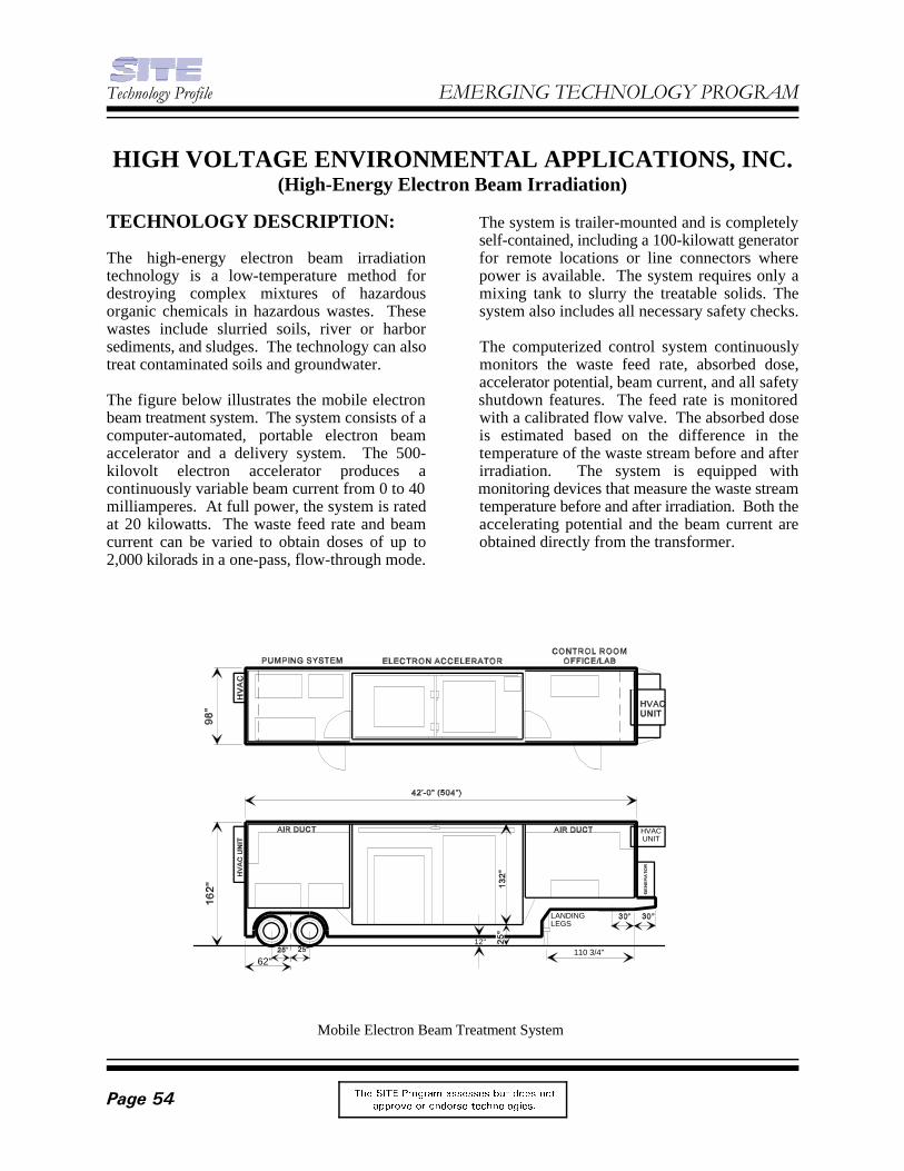
HVACUNIT
LANDINGLEGS
110 3/4"12"
62"
7HFKQRORJ\�3URILOH (0(5*,1*�7(&+12/2*<�352*5$0
7KH 6,7( 3URJUDP DVVHVVHV EXW GRHV QRW
DSSURYH RU HQGRUVH WHFKQRORJLHV�3DJH���
Mobile Electron Beam Treatment System
HIGH VOLTAGE ENVIRONMENTAL APPLICATIONS, INC.(High-Energy Electron Beam Irradiation)
TECHNOLOGY DESCRIPTION: The system is trailer-mounted and is completely
The high-energy electron beam irradiation for remote locations or line connectors wheretechnology is a low-temperature method for power is available. The system requires only adestroying complex mixtures of hazardous mixing tank to slurry the treatable solids. Theorganic chemicals in hazardous wastes. These system also includes all necessary safety checks.wastes include slurried soils, river or harborsediments, and sludges. The technology can also The computerized control system continuouslytreat contaminated soils and groundwater. monitors the waste feed rate, absorbed dose,
The figure below illustrates the mobile electron shutdown features. The feed rate is monitoredbeam treatment system. The system consists of a with a calibrated flow valve. The absorbed dosecomputer-automated, portable electron beam is estimated based on the difference in theaccelerator and a delivery system. The 500- temperature of the waste stream before and afterkilovolt electron accelerator produces a irradiation. The system is equipped withcontinuously variable beam current from 0 to 40 monitoring devices that measure the waste streammilliamperes. At full power, the system is rated temperature before and after irradiation. Both theat 20 kilowatts. The waste feed rate and beam accelerating potential and the beam current arecurrent can be varied to obtain doses of up to obtained directly from the transformer. 2,000 kilorads in a one-pass, flow-through mode.
self-contained, including a 100-kilowatt generator
accelerator potential, beam current, and all safety

)HEUXDU\�����&RPSOHWHG�3URMHFW
7KH 6,7( 3URJUDP DVVHVVHV EXW GRHV QRW
DSSURYH RU HQGRUVH WHFKQRORJLHV� 3DJH���
Except for slurrying, this technology does not In a recent bench-scale study, a multisourcerequire any pretreatment of wastes. hazardous waste leachate containing 1 percent
WASTE APPLICABILITY: treated. In another bench-scale study, a leachate
This technology treats a variety of organic contaminated with PCBs was treated to F039compounds, including wood-treating chemicals, standards.pesticides, insecticides, petroleum residues, andpolychlorinated biphenyls (PCB) in slurried soils, FOR FURTHER INFORMATION:sediments, and sludges.
STATUS: Mary Stinson
High Voltage Environmental Applications, Inc. National Risk Management Research(HVEA), was accepted into the SITE Emerging LaboratoryTechnology Program in 1993. Under this MS-104, Building 10program, HVEA will demonstrate its mobile pilot 2890 Woodbridge Avenueplant on soils, sediments, or sludges at various Edison, NJ 08837-3679hazardous waste sites. Candidate sites are being 908-321-6683identified. On-site studies will last up to 2 Fax: 908-321-6640months.
Initial studies by HVEA have shown that electron William Cooperbeam irradiation effectively removes 2,4,6- High Voltage Environmental Applications, Inc.trinitrotoluene from soil slurries. 9562 Doral Boulevard
As part of the Emerging Technology Program, 305-593-5330HVEA has identified 350 tons of soil Fax: 305-593-0071contaminated with an average Aroclor 1260concentration of about 1,000 milligrams perkilogram. A small 1-ton feasibility study wasconducted in August 1995. After results areavailable from the 1-ton study, HVEA plans tomake its mobile unit available for full-scaleremediations.
dense nonaqueous phase liquid was successfully
containing a light nonaqueous phase liquid
EPA PROJECT MANAGER:
U.S. EPA
TECHNOLOGY DEVELOPER CONTACT:
Miami, FL 33178

7HFKQRORJ\�3URILOH (0(5*,1*�7(&+12/2*<�352*5$0
7KH 6,7( 3URJUDP DVVHVVHV EXW GRHV QRW
DSSURYH RU HQGRUVH WHFKQRORJLHV�3DJH���
Chemical and Biological Treatment Process
INSTITUTE OF GAS TECHNOLOGY(Chemical and Biological Treatment)
TECHNOLOGY DESCRIPTION: and partially oxidized intermediates. In the
The Institute of Gas Technology (IGT) chemical systems degrade the hazardous residual materialsand biological treatment (CBT) process and the partially oxidized intermediates from theremediates sludges, soils, groundwater, and first stage. Chemically treated wastes aresurface water contaminated with organic subjected to cycles of aerobic and anaerobicpollutants, such as polynuclear aromatic degradation, if aerobic or anaerobic treatmenthydrocarbons (PAH) and polychlorinated alone is not sufficient. Several cycles of chemicalbiphenyls. The treatment system (see photograph and biological treatment are also used forbelow) combines two remedial techniques: extremely recalcitrant contaminants.(1) chemical oxidation as pretreatment, and(2) biological treatment using aerobic and WASTE APPLICABILITY:anaerobic biosystems in sequence or alone,depending on the waste. The CBT process uses The CBT process can be applied to soils, sludges,mild chemical treatment to produce intermediates groundwater, and surface water containing (1)that are biologically degraded, reducing the cost high waste concentrations that would typicallyand risk associated with a more severe treatment inhibit bioremediation, or (2) low wasteprocess such as incineration. concentrations for which bioremediation alone is
During the pretreatment stage, the contaminated radionuclides or heavy metals. Depending on thematerial is treated with a chemical reagent that types of heavy metals present, these metals willdegrades the organics to carbon dioxide, water, bioaccumulate in the biomass,
second stage of the CBT process, biological
too slow. The process is not adversely affected by

)HEUXDU\�����&RPSOHWHG�3URMHFW
7KH 6,7( 3URJUDP DVVHVVHV EXW GRHV QRW
DSSURYH RU HQGRUVH WHFKQRORJLHV� 3DJH���
complex with organic or inorganic material in the FOR FURTHER INFORMATION:soil slurries, or become soluble in the recycledwater. EPA PROJECT MANAGER:
The CBT process can be applied to a wide range U.S. EPAof organic pollutants, including alkenes, National Risk Management Researchchlorinated alkenes, aromatics, substituted Laboratoryaromatics, and complex aromatics. 26 West Martin Luther King Drive
STATUS: 513-569-7856
IGT evaluated the CBT process for 2 years underthe SITE Emerging Technology Program. The TECHNOLOGY DEVELOPER CONTACT:Emerging Technology Bul let in Robert Kelley(EPA/540/F-94/540), which details results from Institute of Gas Technologythe evaluation, is available from EPA. Based on 1700 South Mount Prospect Roadresults from the Emerging Technology Program, Des Plaines, IL 60018-1804this technology was invited to participate in the 847-768-0722SITE Demonstration Program. Fax: 847-768-0546 Under the SITE Demonstration Program, IGTplans to conduct a full-scale demonstration of theCBT process on sediments containing PAHs.Different operating scenarios will be used todemonstrate how effectively the CBT processtreats sediments in a bioslurry reactor. Severalsites are being considered for the demonstration.
Ronald Lewis
Cincinnati, OH 45268
Fax: 513-569-7105

7HFKQRORJ\�3URILOH (0(5*,1*�7(&+12/2*<�352*5$0
7KH 6,7( 3URJUDP DVVHVVHV EXW GRHV QRW
DSSURYH RU HQGRUVH WHFKQRORJLHV�3DJH���
Fluid Extraction-Biological Degradation Process
INSTITUTE OF GAS TECHNOLOGY(Fluid Extraction-Biological Degradation Process)
TECHNOLOGY DESCRIPTION: separation solvent, such as water or a water-
The three-step, fluid extraction-biological sent to the final stage of the process, wheredegradation (FEBD) process removes organic bacteria degrade the waste to carbon dioxide andcontaminants from soil (see figure below). The water. Clean extraction solvent is then recycledprocess combines three distinct technologies: for use in the extraction stage.(1) fluid extraction, which removes the organicsfrom contaminated solids; (2) separation, which Organic contaminants are biodegraded intransfers the pollutants from the extract to a aboveground aerobic bioreactors, using mixturesbiologically compatible solvent or activated of bacterial cultures. Specific cultures arecarbon carrier; and (3) biological degradation, selected based on site contaminant characteristics.which destroys the pollutants and leaves For example, if a site is primarily contaminatedinnocuous end-products. with polynuclear aromatic hydrocarbons (PAH),
In the fluid extraction step, excavated soils are hydrocarbons are used. In this way theplaced in a pressure vessel and extracted with a bioreactors can be configured to enhance the raterecirculated stream of supercritical or near- and extent of biodegradation.supercritical carbon dioxide. An extractioncosolvent may be added to enhance the removal Research continues on using bound, activatedof additional contaminants. carbon in a carrier system during the separation
During separation, organic contaminants are pressure conditions to be maintained in the fluidtransferred to a biological ly compatible extraction step, resulting in enhanced extraction
methanol mixture. The separation solvent is then
cultures able to metabolize or cometabolize these
step. Bound activated carbon should allow high-

)HEUXDU\�����&RPSOHWHG�3URMHFW
7KH 6,7( 3URJUDP DVVHVVHV EXW GRHV QRW
DSSURYH RU HQGRUVH WHFKQRORJLHV� 3DJH���
efficiency and decreased extraction time. Bound, The measurable PAHs were biologicallyactivated carbon should also limit the loss of converted in both batch-fed and continuously fed,carbon dioxide, thereby decreasing costs. constantly stirred, tank reactors. The conversionActivated carbon containing the bound PAHs rate and removal efficiency were high in allcould then be treated in the biodegradation step by systems. The PAHs were biologically removed orconverting the carrier system to a biofilm reactor. transformed at short hydraulic retention times.The activated carbon carrier systems could then be All PAHs, including four- to six-ring compounds,recycled into the high-pressure system of the were susceptible to biological removal.extraction and separation steps.
WASTE APPLICABILITY: Emerging Technology Bul let in
This technology removes organic compounds EPA. An article on the project was also submittedfrom contaminated solids. It is more effective on to the Journal of Air and Waste Management.some classes of organics, such as hydrocarbons(for example, gasoline and fuel oils), than on Potential users of the technology have expressedothers, such as halogenated solvents and interest in continuing research, and the technologypolychlorinated biphenyls. The process has also has been invited to participate in the SITEbeen effective in treating nonhalogenated Demonstration Program. The technology wouldaliphatic hydrocarbons and PAHs. be able to remediate other manufactured gas sites,
STATUS: sediments.
This technology was accepted into the SITE FOR FURTHER INFORMATION:Emerging Technology Program in June 1990.The Institute of Gas Technology has evaluated all EPA PROJECT MANAGER:three stages of the technology with soils from a Valdis KukainisSuperfund site and from three other manfactured U.S. EPAgas sites. These soils exhibited a variety of National Risk Management Researchphysical and chemical characteristics. About 85 Laboratoryto 99 percent of detectable PAHs, including two- 26 West Martin Luther King Driveto six-ring compounds, were removed from the Cincinnati, OH 45268soils. 513-569-7655
Results from this project were published in the
(EPA/540/F-94/501), which is available from
wood treatment sites, and contaminated soils and
Fax: 513-569-7620
TECHNOLOGY DEVELOPER CONTACT:Robert PaterekInstitute of Gas Technology1700 South Mount Prospect RoadDes Plaines, IL 60018-1804847-768-0720Fax: 847-768-0546

7HFKQRORJ\�3URILOH (0(5*,1*�7(&+12/2*<�352*5$0
7KH 6,7( 3URJUDP DVVHVVHV EXW GRHV QRW
DSSURYH RU HQGRUVH WHFKQRORJLHV�3DJH���
AGGCOM Pilot Plant
INSTITUTE OF GAS TECHNOLOGY(Fluidized-Bed/Cyclonic Agglomerating Combustor)
TECHNOLOGY DESCRIPTION: low temperature (desorption) to high temperature
The Institute of Gas Technology (IGT) has materials with high calorific values (for example,developed a two-stage, fluidized-bed/cyclonic municipal solid wastes). With a unique fuel andagglomerating combustor (AGGCOM) based on air distribution, most of the fluidized bed isa combination of IGT technologies. In the maintained at 1,500 F( to 2,000 F(, while thecombined system, solid, liquid, and gaseous central hot zone temperature can be variedorganic wastes are destroyed efficiently. Solid, between 2,000 F( and 3,000 F(.nonvolatile, inorganic contaminants are combinedwithin a glassy matrix consisting of discrete When contaminated soils and sludges are fed intopebble-sized agglomerates that are suitable for the fluidized bed, the combustible fraction of thedisposal in a landfill. waste is rapidly gasified and combusted. The
The first stage of the combustor is an contaminants, undergoes a chemicalagglomerating fluidized-bed reactor, which can transformation in the hot zone and isoperate under substoichiometric conditions or agglomerated into glassy pellets. The pellets arewith excess air. The system can operate from essentially nonleachable under the conditions
(agglomeration). The system can also gasify
solid fraction, containing inorganic and metallic

)HEUXDU\�����&RPSOHWHG�3URMHFW
7KH 6,7( 3URJUDP DVVHVVHV EXW GRHV QRW
DSSURYH RU HQGRUVH WHFKQRORJLHV� 3DJH���
of the Toxicity Characteristic Leaching Procedure STATUS:(TCLP). The product gas from the fluidized bedmay contain unburned hydrocarbons, furans, This technology was accepted into the SITEdioxins, and carbon monoxide, as well as carbon Emerging Technology Program in July 1990.dioxide and water, which are the products of Tests conducted in the batch, 6-inch-diameter,complete combustion. fluidized bed have demonstrated that
Product gas from the fluidized bed is fed into the agglomerates, produced at several differentsecond stage of the combustor, where it is further operating conditions from soil spiked with leadcombusted at a temperature of 1,800 F( to 2,400 and chromium compounds, passed the TCLP testF(. The second stage is a high-intensity cyclonic for leachability.combustor and separator that provides sufficientresidence time (0.25 second) to oxidize carbon A pilot-scale combustor with a capacity of 6 tonsmonoxide and organic compounds to carbon per day has been constructed (see photograph ondioxide and water vapor. This stage has a previous page), and testing has produced samplescombined destruction and removal efficiency of of agglomerated soil. Future testing will focus ongreater than 99.99 percent. Volatilized metals are sustained and continuous operation of the pilot-collected downstream in the flue gas scrubber scale plant using different types of soil, as well ascondensate. other feedstocks. Tests with organic and
The two-stage AGGCOM process is based on with the feed soil will also be conducted. A finalIGT's experience with other fluidized-bed and report on the project has been submitted to EPA.cyclonic combustion systems. The patentedsloping-grid design and ash discharge port in this FOR FURTHER INFORMATION:process were initially developed for IGT's U-GAScoal gasification process. The cyclonic combustor EPA PROJECT MANAGER:and separator is a modification of IGT's low- Teri Richardsonemissions combustor. U.S. EPA
WASTE APPLICABILITY: Laboratory
The two-stage AGGCOM process can destroy Cincinnati, OH 45268organic contaminants in gaseous, liquid, and solid 513-569-7949wastes, including soils and sludges. Gaseous Fax: 513-569-7105wastes can be fired directly into the cycloniccombustor. Liquid, sludge, and solid wastes can TECHNOLOGY DEVELOPER CONTACTS:be co-fired directly into the fluidized bed. Solid Amir Rehmat or Michael Mensingerparticles must be less than about 6 millimeters in Institute of Gas Technologydiameter to support fluidized bed operation; there- 1700 South Mount Prospect Roadfore, certain wastes may require grinding or Des Plaines, IL 60018-1804pulverizing prior to remediation. 847-768-0588 or 847-768-0602
Because the solid components in the waste are E-mail: [email protected] or [email protected] above fusion temperature during theagglomeration process, metals and otherinorganic materials are encapsulated andimmobilized within the glassy matrix.
agglomerates can be formed from the soil. The
inorganic hazardous waste surrogates admixed
National Risk Management Research
26 West Martin Luther King Drive
Fax: 847-768-0516

7HFKQRORJ\�3URILOH (0(5*,1*�7(&+12/2*<�352*5$0
7KH 6,7( 3URJUDP DVVHVVHV EXW GRHV QRW
DSSURYH RU HQGRUVH WHFKQRORJLHV�3DJH���
Supercritical Extraction/Liquid Phase Oxidation (SELPhOx) Process
INSTITUTE OF GAS TECHNOLOGY(Supercritical Extraction/Liquid Phase Oxidation)
TECHNOLOGY DESCRIPTION: the original soil organic matrix in place. The
The Institute of Gas Technology's (IGT) a contaminant collection vessel. The activatedSupercritical Extraction/Liquid Phase Oxidation carbon with sorbed contaminants is then(SELPhOx) process (see figure below) removes transported in an aqueous stream to a WAOorganic contaminants from soils and sludges and reactor for destruction. Concentrating the organicdestroys them. SELPhOx combines two contaminants on activated carbon in waterprocessing steps: (1) supercritical extraction provides a suitable matrix for the WAO feed(SCE) of organic contaminants, and (2) wet air stream and improves process economics byoxidation (WAO) of the extracted contaminants. decreasing WAO reactor size. The activatedThe two-step process, linked by a contaminant carbon is regenerated in the WAO reactor withcollection stage, offers great flexibility for minimal carbon loss and can be recycled to theremoving and destroying both high and low contaminant collection vessel.concentrations of organic contaminants.
Combining SCE and WAO in a single two-step makeup activated carbon, and the extractantprocess allows development of a highly efficient (CO ). Primary treatment products includeand economical process for remediating cleaned soil, water, nitrogen (from the air fed tocontaminated soils. Supercritical extraction with the WAO step), and CO . Organic sulfur,carbon dioxide (CO ) removes organic nitrogen, and chloride compounds that may be2
contaminants from the soil while leaving much of present in the original soil or sludge matrix are
contaminants are collected on activated carbon in
The SELPhOx process requires only water, air,
2
2

)HEUXDU\�����&RPSOHWHG�3URMHFW
7KH 6,7( 3URJUDP DVVHVVHV EXW GRHV QRW
DSSURYH RU HQGRUVH WHFKQRORJLHV� 3DJH���
transformed to relatively innocuous compounds in Laboratory-scale SCE tests have been completedthe product water. These compounds include using soils contaminated with PAHs. Operatingsulfuric acid and hydrogen chloride, or their salts. conditions for the SCE stage and the activatedThe treated soil can be returned to the original carbon adsorption stage have been selected. Asite, and the water can be safely discharged after transportable field test unit was constructed andthermal energy recovery and minor secondary tested with PAH-contaminated soil. The finaltreatment. The gas can be depressurized by a report has yet to be submitted by the developer.turbo expander for energy recovery and thenvented through a filter. FOR FURTHER INFORMATION:
WASTE APPLICABILITY: EPA PROJECT MANAGER:
The SELPhOx process removes organic U.S. EPAcontaminants from soils and sludges, including National Risk Management Researchchlorinated and nonchlorinated polynuclear Laboratoryaromatic hydrocarbons (PAH), polychlorinated 26 West Martin Luther King Drivebiphenyls, and other organic contaminants. The Cincinnati, OH 45268process is targeted toward sites that are 513-569-7955contaminated with high levels of these organics Fax: 513-569-7879(hot spots).
The SELPhOx process was accepted into the SITE Michael MensingerEmerging Technology Program in July 1994. The ENDESCO Services, Inc.primary objectives of the project are to (1) 1700 South Mount Prospect Roadevaluate SCE's contaminant removal efficiency, Des Plaines, IL 60018-1804(2) determine the potential for CO recovery and 847-768-06022
reuse, and (3) determine destruction efficiencies Fax: 847-768-0516of extracted contaminants in the WAO process. E-mail: mensinger @endesco.comAnalytical results from the project will providethe necessary information for the full-scaleprocess design.
Valdis R. Kukainis
TECHNOLOGY DEVELOPER CONTACT:

Contaminated Soil
Steam
Organics
To recycled water
Off-site disposal
Recycled water fromextraction step
Batch distillation vessel
Steamstripper
Soil slurry tometal extractionor dewatering vessel
7HFKQRORJ\�3URILOH (0(5*,1*�7(&+12/2*<�352*5$0
7KH 6,7( 3URJUDP DVVHVVHV EXW GRHV QRW
DSSURYH RU HQGRUVH WHFKQRORJLHV�3DJH���
Batch Steam Distillation Step
IT CORPORATION(Batch Steam Distillation and Metal Extraction)
TECHNOLOGY DESCRIPTION: through the system after soluble organics are
The batch steam distillation and metal extraction to the metal extraction step.treatment process is a two-stage system that treatssoils contaminated with organics and inorganics. In the metal extraction step, the soil slurry isThe system uses conventional, readily available washed with hydrochloric acid. Subsequentprocess equipment and does not generate countercurrent batch washing with water removeshazardous combustion products. Hazardous residual acid from the soil. The solids are thenmaterials are separated from soils as concentrates, separated from the final wash solution bywhich can then be disposed of or recycled. gravimetric sedimentation. Most heavy metalsTreated soil can be returned to the site. are converted to chloride salts in this step. The
During treatment, waste soil is slurried in water distillation system, where excess hydrochloricand heated to 100( C. The heat vaporizes volatile acid is recovered (see figure below). Bottomsorganic compounds (VOC) and produces an from the still, which contain heavy metals, areamount of steam equal to 5 to 10 percent of the precipitated as hydroxide salts and are drawn offslurry volume. Resulting vapors are condensed as a sludge for off-site disposal or recovery.and decanted to separate organic contaminantsfrom the aqueous phase. Condensed water from As a batch process, this treatment technology isthis step can be recycled targeted at sites with less than 5,000 tons of soil
removed. The soil is then transferred as a slurry
acid extract stream is then routed to a batch steam

)HEUXDU\�����&RPSOHWHG�3URMHFW
7KH 6,7( 3URJUDP DVVHVVHV EXW GRHV QRW
DSSURYH RU HQGRUVH WHFKQRORJLHV� 3DJH���
Batch Steam Distillation
500-ton site $299-393/ton
2,500-ton site $266-350/ton
Metals Extraction(including acid recovery)
500-ton site $447-619/ton
2,500-ton site $396-545/ton
requiring treatment. Processing time depends on Estimated treatment costs per ton, includingequipment size and batch cycle times; about one capital recovery, for the two treatment steps arebatch of soil can be treated every 4 hours. shown in the box below.
WASTE APPLICABILITY:
This process may be applied to soils and sludgescontaminated with organics, inorganics, andheavy metals.
The batch steam distillation and metal extractionprocess was accepted into the SITE EmergingTechnology Program in January 1988. Theevaluation was completed in 1992. TheEmerg ing Techno logy Bu l l e t i n FOR FURTHER INFORMATION:(EPA/540/F-95/509), which details results fromthe test, is available from EPA. EPA PROJECT MANAGER:
Under the program, three pilot-scale tests have U.S. EPAbeen completed on three soils, for a total of nine National Risk Management Researchtests. The removal rates for benzene, toluene, Laboratoryethylbenzene, and xylene were greater than 26 West Martin Luther King Drive99 percent. The removal rates for chlorinated Cincinnati, OH 45268solvents ranged from 97 to 99 percent. One acid 513-569-7856extraction and two water washes resulted in a 95 Fax: 513-569-7105percent removal rate for heavy metals. Toxicitycharacteristic leaching procedure tests on the TECHNOLOGY DEVELOPER CONTACT:treated soils showed that soils from eight of the Stuart Shealynine tests met leachate criteria. Data were also IT Corporationcollected on the recovery rate for excess acid and 312 Directors Drivethe precipitation rate of heavy metals into a Knoxville, TN 37923-4709concentrate. 423-690-3211
Ronald Lewis
Fax: 423-694-9573

7HFKQRORJ\�3URILOH (0(5*,1*�7(&+12/2*<�352*5$0
7KH 6,7( 3URJUDP DVVHVVHV EXW GRHV QRW
DSSURYH RU HQGRUVH WHFKQRORJLHV�3DJH���
Simplified Process Flow Diagram of Treatment Process
IT CORPORATION(Chelation/Electrodeposition of Toxic Metals from Soils)
TECHNOLOGY DESCRIPTION: EMR. The EMR consists of an electrolytic cell
IT Corporation has conducted laboratory-scale cathode and anode chambers.research on an innovative process that removesheavy metals from contaminated soils and sludges WASTE APPLICABILITY:by forming a soluble chelate. The metals and thechelating agent are then separated from the soils The technology is applicable to a wide variety ofand recovered. metal-contaminated hazardous wastes, including
The treatment employs two key steps (see figure demonstrated the technology’s effectivenessinbelow): (1) a water-soluble chelating agent, such removing lead and cadmium from soils andas ethylenediamine tetraacetic acid, bonds with sludges.heavy metals and forms a chelate; and (2) anelectromembrane reactor (EMR) recovers the STATUS:heavy metals from the chelate and regenerates thechelating agent. This technology was accepted into the SITE
Soils are screened before the chelation step to Jack’s Creek site, located near Maitland,remove large particles such as wood, metal scrap, Pennsylvania, was selected as a site forand large rocks. technology evaluation. The site operated as a
The chelated soil is dewatered to separate the nonferrous metal recycling operation from 1958water-soluble chelating agent from the solid to 1977. A portion of the property is currentlyphase. The separated chelating agent, which operated as a scrap yard. Lead concentrations incontains heavy metals, is then treated in the the contaminated soil used for the evaluation was
with a cation transfer membrane separating the
soils and sludges. To date, IT Corporation has
Emerging Technology Program in July 1994. The
precious and nonprecious metal smelting and

)HEUXDU\�����&RPSOHWHG�3URMHFW
7KH 6,7( 3URJUDP DVVHVVHV EXW GRHV QRW
DSSURYH RU HQGRUVH WHFKQRORJLHV� 3DJH���
approximately 2 percent. Toxicity characteristic FOR FURTHER INFORMATION:leaching procedure (TCLP) analysis on thecontaminated soil showed lead levels of 7.7 EPA PROJECT MANAGER:milli grams per liter (mg/L), which exceeds the George Mooreregulatory limit of 5 mg/L. During the project, IT U.S. EPACorporation established appropriate conditions for National Risk Management Researchlead removal and recovery from the soil and Laboratoryreduced TCLP concentrations of lead in the soil to 26 West Martin Luther King Drivebelow regulatory levels. Cincinnati, OH 45268
513-569-7991Fax: 513-569-7276
TECHNOLOGY DEVELOPER CONTACT:Radha KrishnanIT Corporation11499 Chester RoadCincinnati, OH 45246-4012513-782-4700Fax: 513-782-4663

7HFKQRORJ\�3URILOH (0(5*,1*�7(&+12/2*<�352*5$0
7KH 6,7( 3URJUDP DVVHVVHV EXW GRHV QRW
DSSURYH RU HQGRUVH WHFKQRORJLHV�3DJH���
Mixed Waste Treatment Process
IT CORPORATION(Mixed Waste Treatment Process)
TECHNOLOGY DESCRIPTION: Thermal treatment removes volatile and semi-
IT Corporation's mixed waste treatment process heated in a rotating chamber, volatilizing theintegrates thermal desorption, gravity separation, organic contaminants and any moisture in the soil.water treatment, and chelant extraction The soil passes through the chamber and istechnologies to treat soils contaminated with collected as a dry solid. The volatilized organicshazardous and radioactive constituents. The and water are condensed into separate liquidprocess separates contaminants into distinct phases. The organic phase is decanted andorganic and inorganic phases that can then be removed for disposal. The contaminated aqueousfurther minimized, recycled, or destroyed at phase passes through activated carbon, whichcommercial disposal facilities. Decontaminated removes soluble organics, before the aqueoussoil can then be returned to the site. Each phase is combined with the thermally treated soil.technology has been individually demonstrated onselected contaminated materials. The process Inorganic contaminants are removed by threeflow diagram below shows how the technologies physical and chemical separation techniques:have been integrated to treat mixed waste streams. (1) gravity separation of high density particles
During the initial treatment step, feed soil is (3) chelant extraction of chemically bound metals.prepared using standard techniques, such asscreening, crushing, and grinding to remove Gravity separation is used to separate higheroversized material and provide a consistent feed density particles from common soil.material. Radionuclide contaminants are typically found in
volatile organics from the soil. Soil is indirectly
(2) chemical precipitation of soluble metals and
)HEUXDU\�����&RPSOHWHG�3URMHFW
7KH 6,7( 3URJUDP DVVHVVHV EXW GRHV QRW
DSSURYH RU HQGRUVH WHFKQRORJLHV� 3DJH���
this fraction. The gravity separation device (such (DOE), the U.S. Department of Defense, andas a shaker table, jig, cone, or spiral) depends on commercial sites. Thermal separation hasthe contaminant distribution and the physical removed and recovered polychlorinated biphenylsproperties of the thermally treated soil. from soils contaminated with uranium and
Many radionuclides and other heavy metals are separate DOE gaseous diffusion plants.dissolved or suspended in the aqueous media.These contaminants are separated from the soils Gravity separation of radionuclides has beenand are precipitated. A potassium ferrate for- demonstrated at pilot scale on Johnston Atoll inmulation precipitates radionuclides. The resulting the Pacific Ocean. Gravity separationmicrocrystalline precipitant is removed, allowing successfully removed plutonium from native soils.the aqueous stream to be recycled.
Some insoluble radionuclides remain with the soil formulations has been demonstrated at severalfollowing the gravity separation process. These DOE facilities in laboratory- and full-scale tests.radionuclides are removed by chelant extraction. This treatment approach reduced cadmium,The chelant solution then passes through an ion- copper, lead, nickel, plutonium, silver, uranium,exchange resin to remove the radionuclides, and and zinc to dischargeable levels.the solution is recycled to the chelant extractionstep. Chelant extraction has successfully treated surface
The contaminants are collected as concentrates than 20 years. Similar results are expected forfrom all waste process streams for recovery or subsurface contamination.off-site disposal at commercial hazardous wasteor radiological waste facilities. Decontaminated FOR FURTHER INFORMATION:soil can be returned to the site as clean fill.
WASTE APPLICABILITY: Douglas Grosse
This process treats soils contaminated with National Risk Management Researchorganic, inorganic, and radioactive material. Laboratory
STATUS: Cincinnati, OH 45268
The mixed waste treatment process was selected Fax: 513-569-7585for the SITE Emerging Technology Program inOctober 1991. Bench- and pilot-scale testing was TECHNOLOGY DEVELOPER CONTACT:completed in late 1995; a report detailing Ed Alperinevaluation results was made available from EPA IT Corporationin 1997. Individual components of the treatment 312 Directors Driveprocess have been demonstrated on various Knoxville, TN 37923-4709wastes from the U.S. Department of Energy, 423-690-3211
technetium. These soils were obtained from two
Water treatment using potassium ferrate
contamination in the nuclear industry for more
EPA PROJECT MANAGER:
U.S. EPA
26 West Martin Luther King Drive
513-569-7844
Fax: 423-694-9573
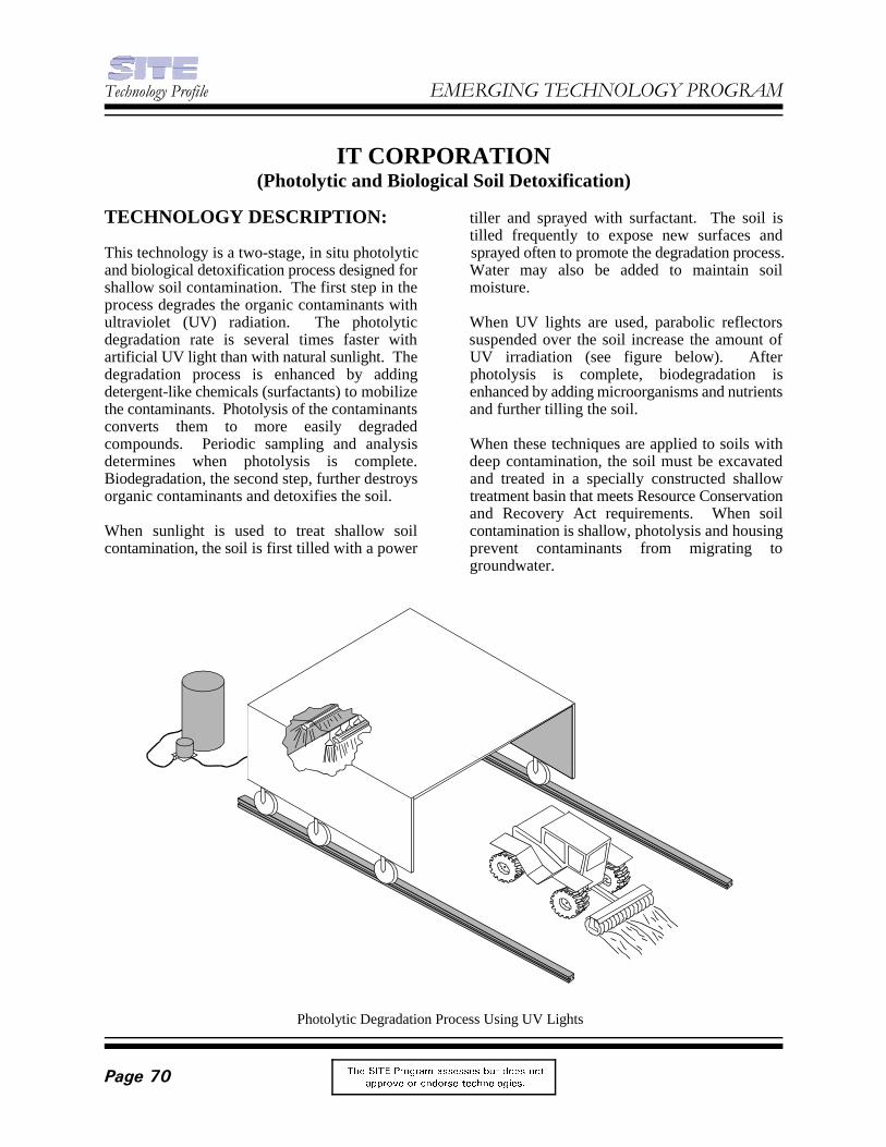
7HFKQRORJ\�3URILOH (0(5*,1*�7(&+12/2*<�352*5$0
7KH 6,7( 3URJUDP DVVHVVHV EXW GRHV QRW
DSSURYH RU HQGRUVH WHFKQRORJLHV�3DJH���
Photolytic Degradation Process Using UV Lights
IT CORPORATION(Photolytic and Biological Soil Detoxification)
TECHNOLOGY DESCRIPTION: tiller and sprayed with surfactant. The soil is
This technology is a two-stage, in situ photolytic sprayed often to promote the degradation process.and biological detoxification process designed for Water may also be added to maintain soilshallow soil contamination. The first step in the moisture.process degrades the organic contaminants withultraviolet (UV) radiation. The photolytic When UV lights are used, parabolic reflectorsdegradation rate is several times faster with suspended over the soil increase the amount ofartificial UV light than with natural sunlight. The UV irradiation (see figure below). Afterdegradation process is enhanced by adding photolysis is complete, biodegradation isdetergent-like chemicals (surfactants) to mobilize enhanced by adding microorganisms and nutrientsthe contaminants. Photolysis of the contaminants and further tilling the soil.converts them to more easily degradedcompounds. Periodic sampling and analysis When these techniques are applied to soils withdetermines when photolysis is complete. deep contamination, the soil must be excavatedBiodegradation, the second step, further destroys and treated in a specially constructed shalloworganic contaminants and detoxifies the soil. treatment basin that meets Resource Conservation
When sunlight is used to treat shallow soil contamination is shallow, photolysis and housingcontamination, the soil is first tilled with a power prevent contaminants from migrating to
tilled frequently to expose new surfaces and
and Recovery Act requirements. When soil
groundwater.

)HEUXDU\�����&RPSOHWHG�3URMHFW
7KH 6,7( 3URJUDP DVVHVVHV EXW GRHV QRW
DSSURYH RU HQGRUVH WHFKQRORJLHV� 3DJH���
The only treatment residuals of the process are The process was also tested with Fenton's reagentsoil contaminated with surfactants and the end chemistry as an alternate method of degradingmetabolites of the biodegradation processes. PCBs to more easily biodegraded compounds. PCB destruction ranged from nondetectable to 35The end metabolites depend on the original percent. Data indicates that no significant changecontaminants. The surfactants are common in PCB chlorine levels occurred during treatment.materials used in agricultural formulations, thesoils can be left on site. Other studies examined PCB biodegradation in
WASTE APPLICABILITY: (2) untreated soil, and (3) soil known to have
This photolytic and biological soil detoxification were as follows:process destroys organics, particularly dioxinssuch as tetrachlorodibenzo-p-dioxin (TCDD), • PCB removal in the UV-treated soil,polychlorinated biphenyls (PCB), other untreated soil, and soil with knownpolychlorinated aromatics, and polynuclear biological activity was higher whenaromatic hydrocarbons. augmented with an isolated PCB
STATUS: • In the untreated soil, biphenyl was more
This technology was accepted into the SITE than 4-bromobiphenyl.Emerging Technology Program in 1989; the • For the treated soil, surfactant treatmentevaluation was completed in 1992. The Emerging may have inhibited microbial activity dueTechnology Report (PB95-159992) is available to high total organic carbon and low pH.for purchase from the National TechnicalInformation Services. The Emerging Technology Isolation and enrichment techniques have made itBulletin (EPA/540/F-94/502) and Emerging possible to isolate microorganisms capable ofTechnology Summary (EPA/540/SR-94/531) biodegrading PCBs in contaminated soil.are available from EPA.
Bench-scale tests conducted on dioxin-contaminated soil showed that the effectiveness of EPA PROJECT MANAGER:surface irradiation to degrade TCDDs or PCBs is Randy Parkerstrongly influenced by soil type. Early tests on U.S. EPAsandy soils showed greater than 90 percent National Risk Management Researchremovals for both TCDDs and PCBs. Using a Laboratory450-watt mercury lamp, the irradiation time was 26 West Martin Luther King Drivemore than 20 hours for greater than 90 percent Cincinnati, OH 45268destruction of TCDD and more than 4 hours for 513-569-7271greater than 90 percent destruction of PCBs. Fax: 513-569-7571However, a high humic content decreased theeffectiveness of the UV photolysis. Soil TECHNOLOGY DEVELOPER CONTACT:contaminated with PCBs in the bench-scale tests Duane Graveshad a high clay content. The highest removal rate IT Corporationfor these soils was 30 percent, measured over a 312 Directors Drive16-hour irradiation time. Bench-scale tests used Knoxville, TN 37923-4709a medium-pressure, mercury UV lamp; sunlight 423-690-3211was ineffective. No significant improvement in Fax: 423-694-3626PCB destruction was achieved using a pulsed UVlamp.
(1) soil treated with a surfactant and UV radiation,
PCB-degrading microorganisms. Study results
degrading microorganism.
efficient at inducing PCB degradation
FOR FURTHER INFORMATION: