Advisory Circular 150/5300-13, Airport Design ...
54
Transcript of Advisory Circular 150/5300-13, Airport Design ...

AC 150/5300-13 CHG 17 9/30/2011 Appendix 1
88
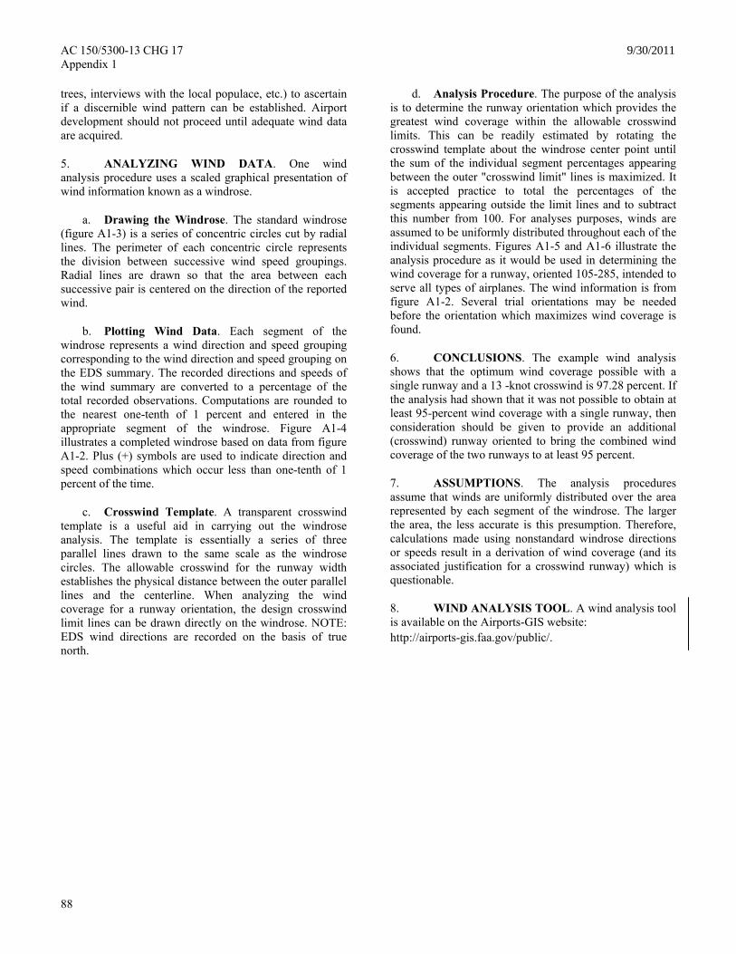
d. Analysis Procedure. The purpose of the analysis is to determine the runway orientation which provides the greatest wind coverage within the allowable crosswind limits. This can be readily estimated by rotating the crosswind template about the windrose center point until the sum of the individual segment percentages appearing between the outer "crosswind limit" lines is maximized. It is accepted practice to total the percentages of the segments appearing outside the limit lines and to subtract this number from 100. For analyses purposes, winds are assumed to be uniformly distributed throughout each of the individual segments. Figures A1-5 and A1-6 illustrate the analysis procedure as it would be used in determining the wind coverage for a runway, oriented 105-285, intended to serve all types of airplanes. The wind information is from figure A1-2. Several trial orientations may be needed before the orientation which maximizes wind coverage is found.
trees, interviews with the local populace, etc.) to ascertain if a discernible wind pattern can be established. Airport development should not proceed until adequate wind data are acquired.
5. ANALYZING WIND DATA. One wind analysis procedure uses a scaled graphical presentation of wind information known as a windrose.
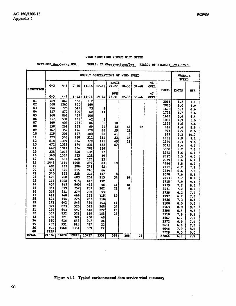
a. Drawing the Windrose. The standard windrose (figure A1-3) is a series of concentric circles cut by radial lines. The perimeter of each concentric circle represents the division between successive wind speed groupings. Radial lines are drawn so that the area between each successive pair is centered on the direction of the reported wind.
b. Plotting Wind Data. Each segment of the windrose represents a wind direction and speed grouping corresponding to the wind direction and speed grouping on the EDS summary. The recorded directions and speeds of the wind summary are converted to a percentage of the total recorded observations. Computations are rounded to the nearest one-tenth of 1 percent and entered in the appropriate segment of the windrose. Figure A1-4 illustrates a completed windrose based on data from figure A1-2. Plus (+) symbols are used to indicate direction and speed combinations which occur less than one-tenth of 1 percent of the time.
6. CONCLUSIONS. The example wind analysis shows that the optimum wind coverage possible with a single runway and a 13 -knot crosswind is 97.28 percent. If the analysis had shown that it was not possible to obtain at least 95-percent wind coverage with a single runway, then consideration should be given to provide an additional (crosswind) runway oriented to bring the combined wind coverage of the two runways to at least 95 percent.
7. ASSUMPTIONS. The analysis procedures assume that winds are uniformly distributed over the area represented by each segment of the windrose. The larger the area, the less accurate is this presumption. Therefore, calculations made using nonstandard windrose directions or speeds result in a derivation of wind coverage (and its associated justification for a crosswind runway) which is questionable.
c. Crosswind Template. A transparent crosswind template is a useful aid in carrying out the windrose analysis. The template is essentially a series of three parallel lines drawn to the same scale as the windrose circles. The allowable crosswind for the runway width establishes the physical distance between the outer parallel lines and the centerline. When analyzing the wind coverage for a runway orientation, the design crosswind limit lines can be drawn directly on the windrose. NOTE: EDS wind directions are recorded on the basis of true north.
8. WIND ANALYSIS TOOL. A wind analysis tool is available on the Airports-GIS website: http://airports-gis.faa.gov/public/.


9/30/2011 AC 150/5300-13 CHG 17 Appendix 1
95-99
This page intentionally left blank.

AC 150/5300-13 CHG 17 9/30/2011 Appendix 2
100
Appendix 2. RUNWAY END SITING REQUIREMENTS
1. PURPOSE. This appendix contains guidance on siting thresholds to meet approach obstacle clearance requirements and departure obstacle clearance requirements.
2. APPLICATION.
a. The threshold should be located at the beginning of the full-strength runway pavement or runway surface. However, displacement of the threshold may be required when an object that obstructs the airspace required for landing and/or departing airplanes is beyond the airport owner's power to remove, relocate, or lower. Thresholds may also be displaced for environmental considerations, such as noise abatement, or to provide the standard RSA and ROFA lengths.
b. When a hazard to air navigation exists, the amount of displacement of the threshold or reduction of the TODA should be based on the operational requirements of the most demanding airplanes. The standards in this appendix minimize the loss of operational use of the established runway and reflect the FAA policy of maximum utilization and retention of existing paved areas on airports.
c. Displacement of a threshold reduces the length of runway available for landings. Depending on the reason for displacement of the threshold, the portion of the runway behind a displaced threshold may be available for takeoffs in either direction and landings from the opposite direction. Refer to Appendix 14, Declared Distances, for additional information.
d. Where specifically noted, the Glidepath Angle (GPA) and Threshold Crossing Height (TCH) of a vertically guided approach may be altered (usually increased) rather than displacing the threshold. Examples of approaches with positive vertical guidance include Instrument Landing System (ILS), Microwave Landing System (MLS), Localizer Performance with Vertical Guidance (LPV), Lateral Navigation/Vertical Navigation (LNAV/VNAV), and required navigation performance (RNP). Alternatively, a combination of threshold displacement and altering of the Glidepath Angle/ Threshold Crossing Height (GPA/TCH) may also be accomplished. Guidelines for maximum and minimum values of TCH and GPA are contained in FAA Order 8260.3, United States Standard for Terminal Instrument Procedures (TERPS). The tradeoff between threshold displacement, TCH, and GPA is complex, but can be analyzed by applying formula contained in the order. Contact the appropriate FAA Airports Regional or District
Office for assistance on the specific requirements and effects of GPA and TCH changes.
3. LIMITATIONS.
a. These standards should not be interpreted as an FAA blanket endorsement of the alternative to displace or relocate a runway threshold. Threshold displacement or relocation should be undertaken only after a full evaluation reveals that displacement or relocation is the only practical alternative.
b. The standards in this appendix are applicable for identifying objects affecting navigable airspace. See Title 14 Code of Federal Regulations Part 77, Safe, Efficient Use, and Preservation of the Navigable Airspace.
4. EVALUATION CONSIDERATIONS.
a. Possible Actions. When a penetration to a threshold siting surface defined in paragraph 5 exists, one or more of the following actions are required:
(1) Approach Surfaces.
(a) The object is removed or lowered to preclude penetration of applicable threshold siting surfaces;
(b) The threshold is displaced to preclude object penetration of applicable threshold siting surfaces, with a resulting shorter landing distance; or
(c) The GPA and/or TCH is/are modified, or a combination of threshold displacement and GPA/TCH increase is accomplished.
(d) Visibility minimums are raised.
(e) Night operations are prohibited unless the obstruction is lighted or an approved Visual Glide Slope Indicator (VGSI) is used.
(2) Departure Surfaces for Designated Runways. The applicability of the surface defined in Table A2-1 is dependant on the designation of primary runway(s) for departure. The Airport Sponsor, through the Airports District Office to the Regional Airspace Procedures Team (RAPT), will identify runway end(s) intended primarily for instrument departures. The determination of primary runway(s) for departure does not prohibit or negate the use of other runways. It only identifies the applicability of the surface in Table A2-1 to the runway end(s).

9/30/2011 AC 150/5300-13 CHG 17 Appendix 2
101
(a) Remove, relocate, or lower (or
both relocate and lower) the object to preclude penetration of applicable siting surfaces unless it is fixed by function and/or designated impracticable. Within 6000' of the Table A2-1 surface origin, objects less than or equal to an elevation determined by application of the formula below are allowable.
E + (0.025 x D)
Where: E = DER elevation D = Distance from OCS origin to object in feet
(b) Decrease the Takeoff Distance Available (TODA) to preclude object penetration of applicable siting surfaces, with a resulting shorter takeoff distance (the Departure End of the Runway (DER) is coincident with the end of the TODA where a clearway is not in effect); or
(c) Modify instrument departures. Contact the Flight Procedures Office (FPO) for guidance. Objects penetrating by < 35 feet may not require actions (a) or (b); however, they will impact departure minimums/climb gradients or departure procedures.
b. Relevant Factors for Evaluation.
(1) Types of airplanes that will use the runway and their performance characteristics.
(2) Operational disadvantages associated with accepting higher landing/takeoff minimums.
(3) Cost of removing, relocating, or lowering the object.
(4) Effect of the reduced available landing/takeoff length when the runway is wet or icy.
(5) Cost of extending the runway if insufficient runway length would remain as a result of displacing the threshold. The environmental aspects of a runway extension need to also be evaluated under this consideration.
(6) Cost and feasibility of relocating visual and electronic approach aids, such as threshold lights, visual glide slope indicator, runway end identification lights, localizer, glide slope (to provide a threshold crossing height of not more than 60 feet
(18 m)), approach lighting system, and runway markings.
(7) Effect of the threshold change on noise abatement.
5. CLEARANCE REQUIREMENTS. The standard shape, dimensions, and slope of the surface used for locating a threshold are dependent upon the type of aircraft operations currently conducted or forecasted, the landing visibility minimums desired, and the types of instrumentation available or planned for that runway end.
a. Approaches with Vertical Guidance. Table A2-1 and Figure A2-1 describe the clearance surfaces required for instrument approach procedures with vertical guidance.
The Glidepath Qualification Surface (GQS) limits the height of obstructions between Decision Altitude (DA) and runway threshold (RWT). When obstacles exceed the height of the GQS, an approach procedure with vertical guidance (ILS, PAR, MLS, TLS, LPV, LNAV/VNAV, etc.) is not authorized. Further information can be found in the appropriate TERPS criterion.
b. Instrument Approach Procedures Aligned with the Runway Centerline. Table A2-1 and Figure A2-1 describe the minimum clearance surfaces required for instrument approach procedures aligned with the runway centerline.
c. Procedures Not Aligned with the Runway Centerline. To accommodate for offset procedures, follow the steps in Figure A2-2 to determine the offset boundary. The surface slope is as specified in the applicable paragraph, according to Table A2-1.
d. Locating or Determining the DER. The standard shape, dimensions, and slope of the departure surface used for determining the DER, as defined in TERPS, is only dependent upon whether or not instrument departures are being used or planned for that runway end. See Table A2-1 and Figures A2-1 and A2-2 for dimensions.
Subparagraph 5d(2) applies only to runways supporting Air Carrier departures and is not to be considered a clearance surface.

AC 150/5300-13 CHG 18 12/30/2011 Appendix 2
102
(1) For Departure Ends at Designated Runways.
(a) No object should penetrate a surface beginning at the elevation of the runway at the DER or end of clearway, and slopes at 40:1. Penetrations by existing obstacles of 35 feet or less would not require TODA reduction or other mitigations found in paragraph 4; however, they may affect new or existing departure procedures.
(2) Departure Runway Ends Supporting Air Carrier Operations.
(a) Objects should be identified that penetrate a one-engine inoperative (OEI) obstacle identification surface (OIS) starting at the DER and at the elevation of the runway at that point, and slopes upward at 62.5:1. Note: A National One Engine Inoperative (OEI) Policy is under development based on the recommendations from the National OEI Pilot Project. Implementation is anticipated for Fall 2012.

12/30/2011 AC 150/5300-13 CHG 18 Appendix 2
103
Table A2-1. Approach/Departure Requirements Table Runway Type DIMENSIONAL STANDARDS*
Feet Slope/ OCS
A B C D E 1 Approach end of runways expected to serve
small airplanes with approach speeds less than 50 knots. (Visual runways only, day/night)
0
60
150
500
2,500
15:1
2 Approach end of runways expected to serve small airplanes with approach speeds of 50 knots or more. (Visual runways only, day/night)
0
125
350
2,250
2,750
20:1
3 Approach end of runways expected to serve large airplanes (Visual day/night); or instrument minimums ≥ 1 statute mile (day only).
0
200
500
1,500
8,500
20:1
4 Approach end of runways expected to support instrument night operations, serving approach category A and B aircraft only. 1
200
200
1,900
10,000 2
0
20:1
5 Approach end of runways expected to support instrument night operations serving greater than approach category B aircraft. 1
200
400
1,900
10,000 2
0
20:1
6 Approach end of runways expected to accommodate instrument approaches having visibility minimums ≥ 3/4 but < 1 statute mile, day or night.
200
400
1,900
10,000 2
0
20:1
7 Approach end of runways expected to accommodate instrument approaches having visibility minimums < 3/4 statute mile or precision approach (ILS, GLS, or MLS), day or night.
200
400
1,900
10,000 2
0
34:1
8 Approach runway ends having Category II approach minimums or greater.
The criteria are set forth in TERPS, Order 8260.3.
9 Approach end of runways expected to accommodate approaches with vertical guidance [Glideslope Qualification Surface (GQS).]
0
1/2 width runway +100
760
10,000 2
0
30:1
10 Departure runway ends for all instrument operations.
04 See Figure A2-3 40:1
11 Departure runway ends supporting Air Carrier operations. 5
04 62.5:1
* The letters are keyed to those shown in Figure A2-1. Notes: 1. Marking & Lighting of obstacle penetrations to this surface or the use of a VGSI, as defined by the TERPS
order, may avoid displacing the threshold. 2. 10,000 feet is a nominal value for planning purposes. The actual length of these areas is dependent upon the
visual descent point position for 20:1 and 34:1 and Decision Altitude point for the 30:1. 3. When obstacles exceed the height of the GQS, an approach procedure with vertical guidance (ILS, PAR MLS,
TLS, LPV, LNAV/VNAV, etc.) is not authorized. No vertical approaches will be authorized until the penetration(s) is/are removed except obstacles fixed by function and/or allowable grading (paragraphs 305 and 308).
4. Dimension A is measured relative to Departure End of Runway (DER) or TODA (to include clearway). 5. Data Collected regarding penetrations to this surface are provided for information and use by the air carriers
operating from the airport. Refer to paragraph 5d(2) for guidance on implementation.
AC 150/5300-13 CHG 17 9/30/2011 Appendix 2
104
6. Surface dimensions/Obstacle Clearance Surface (OCS) slope represent a nominal approach with 3 degree GPA, 50’TCH, <500’ HATh. For specific cases refer to TERPS. The Obstacle Clearance Surface slope (30:1) supports a nominal approach of 3 degrees (also known as the Glide Path Angle). This assumes a threshold crossing height of 50 feet. Three degrees is commonly used for ILS systems and VGSI aiming angles. This approximates a 30:1 approach angle that is between the 34:1 and the 20:1 notice surfaces of Part 77. Surfaces cleared to 34:1 should accommodate a 30:1 approach without any obstacle clearance problems.
7. For runways with vertically guided approaches the criteria in Row 9 is in addition to the basic criteria established within the table, to ensure the protection of the Glidepath Qualification Surface (GQS).
8. For planning purposes, sponsors and consultants determine a tentative Decision Altitude based on a 3 Glidepath angle and a 50-foot Threshold Crossing Height.


AC 150/5300-13 CHG 17 9/30/2011 Appendix 2
106
CL
A
FINAL APPROACHCOARSE
LEGEND:
APPROACH PLANE
OFFSET APPROACH PLANE
D
2C
D
2B
+10°
NAVAID
NOTES:
REFER TO TABLE A2-1 FOR ALL APPLICABLE DIMENSIONAL
TO DETERMINE OFFSET APPROACH PLANE:
A. CONSTRUCT THE APPROACH TRAPEZOID FOR THE RUNWAY TYPE IN TABLE A2-1
B. POINT 1 IS LOCATED AT DISTANCE "A" FROM THE RUNWAY THRESHOLD AND DISTANCE "B" FROM THE RUNWAY CENTERLINE IN THE DIRECTION OF THE OFFSET ( ).
C. FROM POINT 1, EXTEND LINE AT AN ANGLE ( + 10°) A DISTANCE "D" LOCATING POINT 6.
D. CONNECT POINT 6 TO POINT 3.
E. THE OFFSET AREA IS DEFINED BY THE PERIMETER 1-6-3-4-5-1.
1.
2.
= ANGLE OF THE OFFSET FINAL APPROACH (ANGLE FORMED BY THE INTERSECTION OF
LOCATING POINTS 1, 2, 3, 4, AND 5.
THE OFFSET FINAL APPROACH COURSE WITH THE EXTENDED RUNWAY CL).
5
1
6
2
4
3
STANDARDS AND SLOPES.
Figure A2-2. Offset Approach Course

1/3/08 AC 150/5300-13 CHG 12 Appendix 2
107
Figure A2-3. Departure surface for Instrument Runways TERPS (40:1)

AC 150/5300-13 CHG 18 12/30/2011 Appendix 2
108
Figures to be added pending development of National OEI Policy.
Figure A2-4. Nominal One-Engine Inoperative (OEI) Obstacle Identification Surface

9/29/06 AC 150/5300-13 CHG 10 Appendix 3
109
Appendix 3. AIRPORT REFERENCE POINT
1. DISCUSSION.
a. The airport reference point (ARP) geographically locates the airport horizontally. The ARP is normally not monumented or physically marked on the ground. The computation of this point uses only runway length.
b. Meaningful airport reference point computations use the ultimate runway lengths proposed for development. These computations do not use closed or abandoned areas. The FAA approved airport layout plan shows the ultimate development. If there is no airport layout plan, the ultimate runway lengths are the existing runways plus those that have airspace approval, less closed or abandoned areas.
c. The ARP is computed or recomputed as infrequently as possible. The only time that a recomputation is needed is when the proposed ultimate development is changed.
2. SAMPLE COMPUTATION. The following procedure determines the location of the airport reference point used in FAR Part 77 studies.
a. Establish two base lines perpendicular to each other as shown in Figure A3-1. Let the northerly base line be known as B and the westerly as A.
b. Establish the midpoint of each runway.
c. Determine the perpendicular distance from the base lines to the midpoints.
d. Calculate the moment of areas for each base line as shown in Figure A3-2.
e. Divide each moment of area by the sum of areas to determine distance of the ARP from each base line.
f. The location is converted into latitude and longitude.
3. ACCURACY. The latitude and longitude should be to the nearest second. Installation of navigational aids may need coordinates to the nearest tenth of a second. Coordinate with the appropriate FAA Airway Facilities field office to ascertain the need for accuracy closer than the nearest second.
Figure A3-1. Sample layout

AC 150/5300-13 9/29/89 Appendix 3
110
U.S. Customary Units
BASE LINE A:
4,200 x 550 = 2,310,000 3,700 x 1,650 = 6,105,000 7,900 8,415,000
= 8,415,000 = 1,065′ 7,900
BASE LINE B:
4,200 x 2,100 = 8,820,000 3,700 x 2,675 = 9,897,500 7,900 18,717,500
= 18,717,500 = 2,369′ 7,900
Metric Units BASE LINE A:
1 266 x 165 = 207 900 1 110 x 495 = 549 450 2 370 757 350
= 757 350 = 320 m
2 370 BASE LINE B:
1 266 x 630 = 793 800 1 110 x 803 = 891 330 2 370 1 685 130
= 1 685 130 = 710 m
2 370
Note: Since the diagonal runway is to be abandoned, it is not used in the computation.
Figure A3-2. Sample computation – airport reference point


9/30/00 AC 150/5300-13 CHG 6Appendix 4
113
site. If a drainage pipe is required within 300 feet (90 m)of the center of the site, use a nonmetallic or aluminumculvert.
b. Each of the radials is oriented within one minuteof the magnetic bearing indicated by its markings.
c. Mark the date of observation and any annualchange in direction of magnetic north durably and legiblyon the surface of the calibration pad near the magneticnorth mark. It would be well to establish a permanentmonument at some remote location on the true northradial for future reference.
d. The U.S. Geological Survey of the Departmentof Interior is available to conduct the necessary surveys todetermine the difference between true and magneticnorth and the uniformity of this difference. The cost forthis service is that necessary to cover the expense to theU.S. Geological Survey. Requests for this service shouldbe made to the following:
National Geometric Information CenterU.S. Geomagnetic Survey
Box 25046 MS 968Denver, Colorado 80225-0046 USA
Tel: 1(303)273-8486 Fax: 1(303)273-8450Public Web Site: http://geomag.usgs.gov
There are also many other competent registered surveyorsor engineers who are capable of performing thesesurveys. It is recommended that a qualified engineer beemployed to lay out the work in the field and to designthe pavement for the critical aircraft that can reasonablybe expected to use the pad.
e. After all construction work on the compass padis completed, it is advisable to have the pad magneticallyresurveyed to guard against the possibility ofobjectionable magnetic materials being introduced duringthe construction.
f. Magnetic surveys of existing compasscalibration pads should be performed at regular intervalsof 5 years or less. Additional surveys should beperformed after major construction of utility lines,buildings, or any other structures within 600 feet (180 m)of the center of the pad.
7. VOR CHECKPOINT. At some airports, it may beadvantageous to collocate a VOR checkpoint with thecompass calibration pad. In such instances, therequirements presented in paragraph 201.3212 of FAAHandbook OA P 8200.1, United States Standard FlightInspection Manual, should be followed.

AC 150/5300-13 9/29/89Appendix 4
114
Figure A4-1. Marking layout and details of wheel block


9/29/06 AC 150/5300-13 CHG 10 Appendix 6
125
Appendix 6. METRIC CONVERSION AND TYPICAL AIRPORT LAYOUT PLAN
This appendix was cancelled by AC 150/5070-6, Airport Master Plans. Please replace pages 125–130.

AC 150/5300-13 CHG 10 9/29/06 Appendix 6
126 through 130
This page intentionally left blank.

9/29/06 AC 150/5300-13 CHG 10 Appendix 7
131
Appendix 7. AIRPORT LAYOUT PLAN COMPONENTS AND PREPARATION
This appendix was cancelled by AC 150/5070-6, Airport Master Plans. Please replace pages 131–138.

AC 150/5300-13 CHG 10 9/29/06 Appendix 7
132 through 138
This page intentionally left blank.

10/1/02 AC 150/5300-13 CHG 7 Appendix 8
139
Appendix 8. RUNWAY DESIGN RATIONALE 1. SEPARATIONS. Dimensions shown in tables 2-1, 2-2, 3-1, 3-2, and 3-3 may vary slightly due to rounding off. a. Runway to holdline separation is derived from landing and takeoff flight path profiles and the physical characteristics of airplanes. The runway to holdline standard satisfies the requirement that no part of an airplane (nose, wingtip, tail, etc.) holding at a holdline penetrates the obstacle free zone (OFZ). Additionally, the holdline standard keeps the nose of the airplane outside the runway safety area (RSA) when holding prior to entering the runway. When the airplane exiting the runway is beyond the standard holdline, the tail of the airplane is also clear of the RSA. Additional holdlines may be required to prevent airplane, from interfering with the ILS localizer and glide slope operations. b. Runway to parallel taxiway/taxilane separation is determined by the landing and takeoff flight path profiles and physical characteristics of airplanes. The runway to parallel taxiway/taxilane standard precludes any part of an airplane (tail, wingtip, nose, etc.) on a parallel taxiway/taxilane centerline from being within the runway safety area or penetrating the OFZ. c. Runway to airplane parking areas is determined by the landing and takeoff flight path profiles and physical characteristics of airplanes. The runway to parking area standard precludes any part of a parked airplane (tail, wingtip, nose, etc.) from being within the runway object free area or penetrating the OFZ. 2. OBSTACLE FREE ZONE (OFZ). The portion of the OFZ within 200 feet (60 m) of the runway centerline is required for departure clearance. The additional OFZ, beyond 200 feet (60 m) from runway centerline, is required to provide an acceptable accumulative target level of safety without having to adjust minimums. The level of safety for precision instrument operations is determined by the collision risk model. The collision risk model is a computer program developed from observed approaches and missed approaches. It provides the probability of an airplane passing through any given area along the flight path of the airplane. To obtain an acceptable accumulative target level of safety with objects in the OFZ, operating minimums may have to be adjusted. 3. RUNWAY SAFETY AREA.
a. Historical Development. In the early years of aviation, all airplanes operated from relatively unimproved
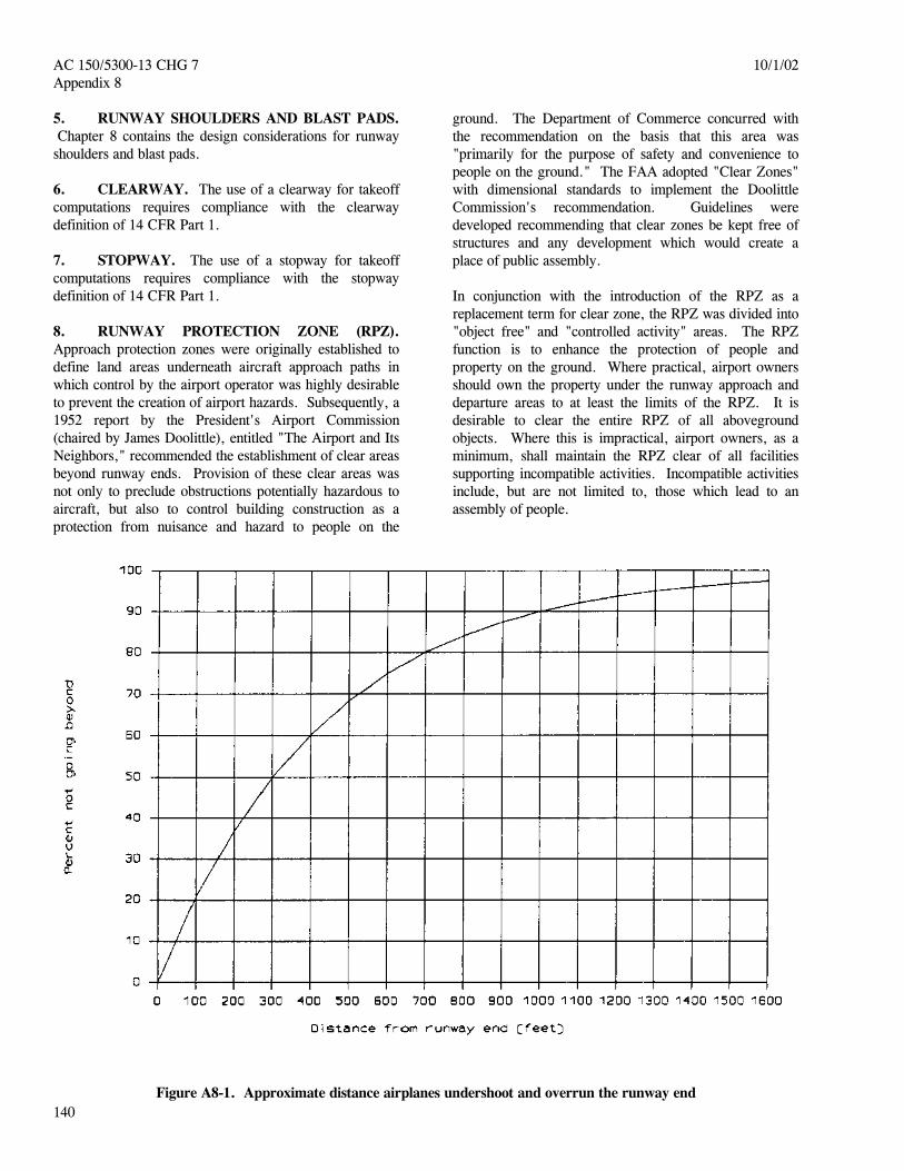
airfields. As aviation developed, the alignment of takeoff and landing paths centered on a well defined area known as a landing strip. Thereafter, the requirements of more advanced airplanes necessitated improving or paving the center portion of the landing strip. The term "landing strip" was retained to describe the graded area surrounding and upon which the runway or improved surface was constructed. The primary role of the landing strip changed to that of a safety area surrounding the runway. This area had to be capable, under normal (dry) conditions, of supporting airplanes without causing structural damage to the airplanes or injury to their occupants. Later, the designation of the area was changed to "runway safety area," to reflect its functional role. The runway safety area enhances the safety of airplanes which undershoot, overrun, or veer off the runway, and it provides greater accessibility for firefighting and rescue equipment during such incidents. Figure A8-1 depicts the approximate percentage of airplanes undershooting and overrunning the runway which stay within a specified distance from the runway end. The runway safety area is depicted in figure 3-1 and its dimensions are given in tables 3-1, 3-2, and 3-3.
b. Recent Changes. FAA recognizes that incremental improvements inside standard RSA dimensions can enhance the margin of safety for aircraft. This is a significant change from the earlier concept where the RSA was deemed to end at the point it was no longer graded and constructed to standards. Previously, a modification to standards could be issued if the actual, graded and constructed RSA did not meet dimensional standards as long as an acceptable level of safety was provided. Today, modifications to standards no longer apply to runway safety areas. (See paragraph 6) Instead, FAA airport regional division offices are required to maintain a written determination of the best practicable alternative for improving non-standard RSAs. They must continually analyze the non-standard RSA with respect to operational, environmental, and technological changes and revise the determination as appropriate. Incremental improvements are included in the determination if they are practicable and they will enhance the margin of safety. 4. RUNWAY OBJECT FREE AREA (ROFA). The ROFA is a result of an agreement that a minimum 400-foot (120 m) separation from runway centerline is required for equipment shelters, other than localizer equipment shelters. The aircraft parking limit line no longer exists as a separate design standard. Instead, the separations required for parked aircraft and the building restriction line from the runway centerline are determined by object clearing criteria.
AC 150/5300-13 CHG 7 10/1/02 Appendix 8
140
5. RUNWAY SHOULDERS AND BLAST PADS. Chapter 8 contains the design considerations for runway shoulders and blast pads. 6. CLEARWAY. The use of a clearway for takeoff computations requires compliance with the clearway definition of 14 CFR Part 1. 7. STOPWAY. The use of a stopway for takeoff computations requires compliance with the stopway definition of 14 CFR Part 1. 8. RUNWAY PROTECTION ZONE (RPZ). Approach protection zones were originally established to define land areas underneath aircraft approach paths in which control by the airport operator was highly desirable to prevent the creation of airport hazards. Subsequently, a 1952 report by the President's Airport Commission (chaired by James Doolittle), entitled "The Airport and Its Neighbors," recommended the establishment of clear areas beyond runway ends. Provision of these clear areas was not only to preclude obstructions potentially hazardous to aircraft, but also to control building construction as a protection from nuisance and hazard to people on the
ground. The Department of Commerce concurred with the recommendation on the basis that this area was "primarily for the purpose of safety and convenience to people on the ground." The FAA adopted "Clear Zones" with dimensional standards to implement the Doolittle Commission's recommendation. Guidelines were developed recommending that clear zones be kept free of structures and any development which would create a place of public assembly. In conjunction with the introduction of the RPZ as a replacement term for clear zone, the RPZ was divided into "object free" and "controlled activity" areas. The RPZ function is to enhance the protection of people and property on the ground. Where practical, airport owners should own the property under the runway approach and departure areas to at least the limits of the RPZ. It is desirable to clear the entire RPZ of all aboveground objects. Where this is impractical, airport owners, as a minimum, shall maintain the RPZ clear of all facilities supporting incompatible activities. Incompatible activities include, but are not limited to, those which lead to an assembly of people.
Figure A8-1. Approximate distance airplanes undershoot and overrun the runway end


9/30/2011 AC 150/5300-13 CHG 17 Appendix 11
153
Appendix 11. COMPUTER PROGRAM
This appendix was cancelled. Please replace pages 153-164.

AC 150/5300-13 CHG 17 9/30/2011 Appendix 11
154 through 164
This page intentionally left blank.