Advisory - AviationManuals, LLC Link Communication (CPDLC). ADS-C provides a direct connection...
146
“DRAFT” U.S. Department of Transportation Federal Aviation Administration Advisory Circular Subject: Data Link Communications Date: DRAFT AC No:90-117 Initiated by: AFS-400 Change: This advisory circular (AC) applies to all pilots, certificate holders, operators, and/or program managers conducting data link communication operations and to those providing data communication services on behalf of operators to meet Federal Aviation Administration (FAA) and International Civil Aviation Organization (ICAO) requirements. The AC provides guidance for data link communications eligibility and compliance using Future Air Navigation Systems (FANS) 1/A(+) and Aeronautical Telecommunications Network (ATN). It defines performance concepts, data link systems, and data link services available within the National Airspace System (NAS) and international operations. This AC addresses Automatic Dependent Surveillance – Contract (ADS-C) and Controller-Pilot Data Link Communication (CPDLC). ADS-C provides a direct connection between the aircraft automation and ground automation, to exchange status information concerning the flight including automated pilot position reports. CPDLC provides efficient digital communication without frequency congestion or misunderstandings and misinterpretations common to voice communication. CPDLC – Departure Clearance (CPDLC-DCL) service provides automated DCLs with the capability to amend clearances prior to departure. Pre-Departure Clearances (PDC) and Aircraft Communications Addressing and Reporting System (ACARS) are discussed as part of the overall data link services. Guidance is also provided for performance monitoring and problem reporting. John S. Duncan Director, Flight Standards Service
Transcript of Advisory - AviationManuals, LLC Link Communication (CPDLC). ADS-C provides a direct connection...

“DRAFT”
U.S. Department of Transportation Federal Aviation Administration
Advisory Circular
Subject: Data Link Communications Date: DRAFT AC No:90-117 Initiated by: AFS-400 Change:
This advisory circular (AC) applies to all pilots, certificate holders, operators, and/or program managers conducting data link communication operations and to those providing data communication services on behalf of operators to meet Federal Aviation Administration (FAA) and International Civil Aviation Organization (ICAO) requirements.
The AC provides guidance for data link communications eligibility and compliance using Future Air Navigation Systems (FANS) 1/A(+) and Aeronautical Telecommunications Network (ATN). It defines performance concepts, data link systems, and data link services available within the National Airspace System (NAS) and international operations.
This AC addresses Automatic Dependent Surveillance – Contract (ADS-C) and Controller-Pilot Data Link Communication (CPDLC). ADS-C provides a direct connection between the aircraft automation and ground automation, to exchange status information concerning the flight including automated pilot position reports. CPDLC provides efficient digital communication without frequency congestion or misunderstandings and misinterpretations common to voice communication. CPDLC – Departure Clearance (CPDLC-DCL) service provides automated DCLs with the capability to amend clearances prior to departure. Pre-Departure Clearances (PDC) and Aircraft Communications Addressing and Reporting System (ACARS) are discussed as part of the overall data link services. Guidance is also provided for performance monitoring and problem reporting.
John S. Duncan Director, Flight Standards Service

DATE “DRAFT” AC 90-117
CONTENTS Paragraph Page
Chapter 1. General ...................................................................................................................... 1-1
1.1 Purpose .......................................................................................................................... 1-1
1.2 Cancellation .................................................................................................................. 1-1
1.3 Applicability.................................................................................................................. 1-1
1.4 Scope ............................................................................................................................. 1-1
1.5 AC Format..................................................................................................................... 1-1
1.6 Version References ....................................................................................................... 1-2
1.7 FAA Document References .......................................................................................... 1-2
1.8 References ..................................................................................................................... 1-2
1.9 AC Terms ...................................................................................................................... 1-4
1.10 Airworthiness .............................................................................................................. 1-4
1.11 Alternative Method ...................................................................................................... 1-4
1.12 Regulatory Basis for Data Link Communication ........................................................ 1-4
1.13 Where You Can Find This AC .................................................................................... 1-5
1.14 AC Feedback Form ..................................................................................................... 1-5
Chapter 2. Data Link Communication Overview ....................................................................... 2-1
2.1 Introduction ................................................................................................................... 2-1
2.2 What Are Data Link Communications? ........................................................................ 2-1
2.3 FANS ............................................................................................................................ 2-2
2.4 Data Link Uses .............................................................................................................. 2-2
2.5 ATN .............................................................................................................................. 2-4
2.6 B2 .................................................................................................................................. 2-4
2.7 Integration of FANS and ATN...................................................................................... 2-4
2.8 ACARS ATS ................................................................................................................. 2-4
2.9 Tower Data Link System (TDLS) ................................................................................. 2-5
2.10 CPDLC-DCL ............................................................................................................... 2-5
2.11 PDC ............................................................................................................................. 2-7
2.12 Data Authority ............................................................................................................. 2-8
2.13 ATSUs and Aircraft Interoperability ........................................................................... 2-9
2.14 Performance-Based Communication and Surveillance (PBCS) Concept ................. 2-16
ii

DATE “DRAFT” AC 90-117
2.15 RCP and RSP Specifications Supporting ATM Operations ...................................... 2-17
2.16 Required Surveillance Performance (RSP) ............................................................... 2-22
2.17 High Frequency Data Link (HFDL) .......................................................................... 2-27
2.18 Future NAS Data Link Communication Services ..................................................... 2-28
2.19 Data Communication Services Strategy .................................................................... 2-29
Chapter 3. Aircraft Eligibility ..................................................................................................... 3-1
3.1 Introduction ................................................................................................................... 3-1
3.2 Aircraft Eligibility ......................................................................................................... 3-1
3.3 Statement of Compliance (SOC) ................................................................................... 3-1
3.4 Configuration Control ................................................................................................... 3-3
3.5 Maintenance .................................................................................................................. 3-3
Chapter 4. Communication Service Providers (CSP) ................................................................. 4-1
4.1 CSP for Oceanic and Remote Continental Operations ................................................. 4-1
4.2 RCP 240 CSP Allocations............................................................................................. 4-2
4.3 RCP 400 CSP Allocations............................................................................................. 4-2
4.4 RSP Specifications ........................................................................................................ 4-3
4.5 CSP for U.S. Operations ............................................................................................... 4-5
4.6 CSP Monitoring ............................................................................................................ 4-7
Chapter 5. Operational Use Of Data Link Communications ...................................................... 5-1
5.1 Operational Use............................................................................................................. 5-1
5.2 Data Link Operational Guidance .................................................................................. 5-1
5.3 Logon ............................................................................................................................ 5-2
5.4 En Route ........................................................................................................................ 5-3
5.5 Voice Monitoring .......................................................................................................... 5-4
5.6 Free Text Messages ....................................................................................................... 5-4
5.7 Data Link Communication Failures .............................................................................. 5-5
5.8 ADS-C ........................................................................................................................... 5-5
5.9 Exiting CPDLC and ADS-C Areas ............................................................................... 5-6
5.10 Logoff .......................................................................................................................... 5-6
iii

DATE “DRAFT” AC 90-117
Chapter 6. Performance Monitoring ........................................................................................... 6-1
6.1 Performance Monitoring ............................................................................................... 6-1
6.2 Oceanic and Remote Continental Airspace .................................................................. 6-1
6.3 Performance Website .................................................................................................... 6-2
6.4 Substandard Performance ............................................................................................. 6-2
6.5 Corrective Aircraft Action ............................................................................................ 6-2
6.6 Data Link Performance Eligibility ................................................................................ 6-2
6.7 Procedures to Report Problems ..................................................................................... 6-2
6.8 Performance Monitoring in the National Airspace System (NAS) ............................... 6-2
Chapter 7. Training ..................................................................................................................... 7-1
7.1 Training Documentation ............................................................................................... 7-1
7.2 Objectives...................................................................................................................... 7-1
7.3 Ground and Flight Training .......................................................................................... 7-1
7.4 Pilot Knowledge Subject Areas .................................................................................... 7-2
7.5 Pilot Procedural Training Items .................................................................................... 7-3
7.6 Dispatcher Training....................................................................................................... 7-4
7.7 Maintenance Training ................................................................................................... 7-4
Chapter 8. Reports ...................................................................................................................... 8-1
8.1 Introduction ................................................................................................................... 8-1
8.2 Oceanic and Remote Continental Problem Reporting .................................................. 8-1
8.3 NAS Problem Reporting ............................................................................................... 8-1
Appendix A. Foreign Operators ................................................................................................. A-1
A.1 General ......................................................................................................................... A-1
A.2 Title 14 CFR Part 129 .................................................................................................. A-1
A.3 Application Process ..................................................................................................... A-1
A.4 Unique Address ............................................................................................................ A-1
A.5 Performance Standard for Two-Way Data Link Communications.............................. A-1
A.6 Training ........................................................................................................................ A-2
A.7 Unsafe Performance or Conditions .............................................................................. A-2
Appendix B. Data Link Communications Minimum Equipment List (MEL) and Master Minimum Equipment List (MMEL) Provisions ....................................................B-1
B.1 Inoperative Equipment ..................................................................................................B-1
iv

DATE “DRAFT” AC 90-117
Appendix C. Summary of Airspace Requirements .....................................................................C-1
C.1 Summary of Airspace Requirements ............................................................................C-1
Appendix D. Flight Planning ..................................................................................................... D-1
D.1 Filing Required Communication Performance (RCP)/Required Surveillance Performance (RSP) Capabilities .................................................................................. D-1
D.2 Regulatory Basis .......................................................................................................... D-1
D.3 Example ....................................................................................................................... D-2
D.4 Item 10a Descriptors .................................................................................................... D-2
D.5 Item 10b Descriptors .................................................................................................... D-3
D.6 Item 18 RSP Specification ........................................................................................... D-4
Appendix E. Voice Phraseology ................................................................................................. E-1
Appendix F. Controller-Pilot Data Link Communication (CPDLC) Uplink and Downlink Tables .................................................................................................................... F-1
Appendix G. Terminology and Acronyms................................................................................ G-1
G.1 Terminology ................................................................................................................. G-1
G.2 Acronyms ..................................................................................................................... G-5
List of Figures Figure 2-1. Overview Data Link System ..................................................................................... 2-1
Figure 2-2. ADS-C Event Sequence ............................................................................................ 2-3
Figure 2-3. Data Link Communication Services on Departure Procedure .................................. 2-6
Figure 2-4. Next Data Authority Notification.............................................................................. 2-9
Figure 2-5. Air Traffic Service Unit (ATSU) and Aircraft Interoperability Designators .......... 2-10
Figure 2-6. Performance-Based CNS/ATM Model ................................................................... 2-16
Figure 2-7. Actual Communications Performance (ACP) ......................................................... 2-18
Figure 2-8. RCP 240 Illustration ................................................................................................ 2-19
Figure 2-9. RCP 400 Illustration ................................................................................................ 2-21
Figure 2-10. RSP 180 Illustration .............................................................................................. 2-24
Figure 2-11. RSP 400 Performance ........................................................................................... 2-26
Figure 2-12. Data Communication Services Strategy ................................................................ 2-28
v

DATE “DRAFT” AC 90-117
List of Tables Table 2-1. PDC vs. CPDLC-DCL................................................................................................ 2-8
Table 2-2. Interoperability Designators and Descriptions ......................................................... 2-11
Table 2-3. Types of Data Link Systems and Operations ........................................................... 2-15
Table 2-4. RCP 240 Transaction Time and Continuity Allocations—CPDLC ......................... 2-20
Table 2-5. RCP 240 Availability Criteria (Aircraft System) ..................................................... 2-20
Table 2-6. RCP 240 Integrity Criteria (Aircraft System) .......................................................... 2-20
Table 2-7. RCP 400 Transaction Time and Continuity Allocations—CPDLC ......................... 2-22
Table 2-8. RCP 400 Availability Criteria (Aircraft System) ..................................................... 2-22
Table 2-9. RCP 240 Integrity Criteria (Aircraft System) .......................................................... 2-22
Table 2-10. RSP 180 Surveillance Data Delivery and Continuity Allocations—ADS-C ......... 2-25
Table 2-11. RSP 180 Availability Criteria (Aircraft System).................................................... 2-25
Table 2-12. RSP 180 Integrity Criteria (Aircraft System) ......................................................... 2-25
Table 2-13. RSP 400 Surveillance Data Delivery and Continuity Allocations—ADS-C ......... 2-27
Table 2-14. RSP 180 Availability Criteria (Aircraft System).................................................... 2-27
Table 2-15. RSP 180 Integrity Criteria (Aircraft System) ......................................................... 2-27
Table 4-1. RCP 240 Transaction Time and Continuity Allocations to CSP ................................ 4-2
Table 4-2. RCP 240 CSP Availability and Outages Parameters .................................................. 4-2
Table 4-3. RCP 400 Transaction Time and Continuity to CSP Allocation ................................. 4-3
Table 4-4. RCP 400 Availability and Outages Parameters .......................................................... 4-3
Table 4-5. RSP 180 Data Delivery Time and Continuity Criteria ............................................... 4-4
Table 4-7. RSP 400 Data Delivery Time and Continuity Criteria ............................................... 4-4
Table 4-8. RSP 400 Availability and Outages Parameters .......................................................... 4-5
Table 4-9. Data Communications Network Services (DCNS) Performance Baseline ................ 4-6
Table 5-1. CPDLC Connection Failure Responses...................................................................... 5-4
Table B-1. Minimum Equipment List Example ......................................................................... B-1
Table B-2. Example of a Data Link Communication MMEL Provision .................................... B-2
Table C-1. Summary Airspace Requirements ............................................................................ C-1
Table C-2. Subnetwork Designators ........................................................................................... C-2
Table C-3. Preferred Original Equipment Manufacturer Annotation ......................................... C-3
Table D-1. Item 10a Flight Plan COM Descriptors .................................................................... D-3
Table D-2. Item 10b Flight Plan Descriptors for Surveillance Equipment................................. D-4
Table E-1. Voice Phraseology Related to Controller-Pilot Data Link Communication (CPDLC) from Flightcrew ...................................................................................... E-1
Table E-2. Voice Phraseology Related to CPDLC from the ATSU ............................................ E-2
vi

DATE “DRAFT” AC 90-117
Table F-1. Color Key ................................................................................................................... F-1
Table F-2. Response Attribute of CPDLC Message Element for Uplink Messages ................... F-1
Table F-3. Response Attribute of CPDLC Message Element for Downlink Messages .............. F-2
Table F-4. Route Uplink Message Elements (RTEU) ................................................................. F-3
Table F-5. Route Downlink Message Elements (RTED) ............................................................ F-7
Table F-6. Lateral Uplink Message Elements (LATU) ............................................................... F-8
Table F-7. Lateral Downlink Message Elements (LATD) ........................................................ F-11
Table F-8. Level Uplink Message Elements (LVLU) ............................................................... F-13
Table F-9. Level Downlink Message Elements (LVLD) ........................................................... F-20
Table F-10. Crossing Constraint Uplink Messages (CSTU) ..................................................... F-24
Table F-11. Speed Uplink Messages (SPDU)............................................................................ F-28
Table F-13. Air Traffic Advisory Uplink Messages (ADVU) ................................................... F-32
Table F-14. Air Traffic Advisory Downlink Messages (ADVD) .............................................. F-36
Table F-15. Voice Communication Uplink Messages (COMU) ............................................... F-37
Table F-16. Voice Communication Downlink Messages (COMD) .......................................... F-39
Table F-17. Spacing Uplink Messages (SPCU) ......................................................................... F-40
Table F-18. Spacing Downlink Messages (SPCD) .................................................................... F-42
Table F-19. Emergency/Urgency Uplink Messages (EMGU) ................................................... F-44
Table F-20. Emergency/Urgency Downlink Messages (EMGD) .............................................. F-45
Table F-21. Standard Response Uplink Messages (RSPU) ....................................................... F-46
Table F-22. Standard Response Downlink Messages (RSPD) .................................................. F-47
Table F-23. Supplemental Uplink Messages (SUPU) ............................................................... F-48
Table F-24. Supplemental Downlink Messages (SUPD) .......................................................... F-49
Table F-25. Free Text Uplink Messages (TXTU) ..................................................................... F-49
Table F-26. Free Text Downlink Messages (TXTD)................................................................. F-50
Table F-27. System Management Uplink Messages (SYSU) .................................................... F-51
Table F-28. System Management Downlink Messages (SYSD) ............................................... F-53
Table F-29. FANS 1/A Uplink Messages Not Recommended for Use ..................................... F-54
Table F-30. FANS 1/A Downlink Messages Not Recommended for Use ................................ F-57
Table F-31. ATN B1 Uplink Messages Not Recommended for Use ........................................ F-58
Table F-32. ATN B1 Downlink Messages Not Recommended for Use.................................... F-58
vii
DATE “DRAFT” AC 90-117
CHAPTER 1. GENERAL
1.1 Purpose. This advisory circular (AC) provides guidance for aircraft eligibility and operational use of data link communications in the United States, in oceanic and remote continental airspace, and in foreign countries which adopt International Civil Aviation Organization (ICAO) standards for data communication. This document also provides explanations of data link systems to inform those who may be new to using digital aircraft communication and surveillance systems. This AC provides new guidance associated with updated and/or new operational authorization. The publication schedule provides operators with sufficient time to prepare for the initial implementation of Performance-based Communication and Surveillance (PBCS) in the North Atlantic (NAT) by March 2018.
1.2 Cancellation. AC 120-70C, Operational Authorization Process for Use of Data Link Communication System, dated August 3, 2015, is cancelled.
1.3 Applicability. This AC applies to operators under Title 14 of the Code of Federal Regulations (14 CFR) parts 91, 91 subpart K (part 91K), 121, 125, 129, and 135 conducting data link communications operations in the United States or in oceanic and remote continental airspace. This AC also applies where the foreign authority has adopted ICAO data link communication standards.
Note: Part 91 operators do not require operational authorization for the use of data link in the United States For data link operations in oceanic and remote continental airspace and/or foreign countries requiring specific data link approval, part 91 operators may apply to their Flight Standards District Office (FSDO) for a letter of authorization (LOA).
1.4 Scope. The scope of this AC is limited to the interoperability designators listed in Table 2-2, Interoperability Designators and Descriptions. Aeronautical Information Services (AIS) and Meteorological Information (METI) Services are excluded from the scope of this AC.
1.5 AC Format. Chapter 2, Data Link Communication Overview, is intended to inform those not familiar with data link communications. Chapters 3-8 provide aircraft eligibility and operational guidance with the following topics:
• Chapter 3, Aircraft Eligibility,
• Chapter 4, Communication Service Providers (CSP),
• Chapter 5, Operational Use of Data Link Communications,
• Chapter 6, Performance Monitoring,
• Chapter 7, Training, and
• Chapter 8, Reports.
1-1

DATE “DRAFT” AC 90-117
1.6 Version References. The most current version of a document is designated by parentheses ( ) placed at the end of the number designation. Specific versions are indicated by a letter. If no letter appears after the document designation, then all versions of the document are applicable. As a convenience, most references are hyperlinked to a website containing the most current document. The most current ACs or Technical Standard Orders (TSO) are available by clicking the following links:
1. ACs.
2. TSOs.
1.7 FAA Document References. This AC, along with AC 20-140( ), provides all the information necessary for data link communication compliance in the United States and in oceanic and remote continental airspace and should be considered the “source documents” for the operational use of data link by U.S. operators and pilots. ICAO documents are referenced in this document as a convenience to the operator.
1.8 References.
1. Title 14 CFR Parts 21, 23, 25, 27, 29, 43, 91, 91K, 121, 125, 129, and 135.
2. ACs:
• AC 20-140( ), Guidelines for Design Approval of Aircraft Data LinkCommunication Systems Supporting Air Traffic Services (ATS).
• AC 20-160( ), Onboard Recording of Controller Pilot Data Link Communicationin Crash Survivable Memory.
3. TSOs:
• TSO-C160a, Very High Frequency (VHF) Digital Link (VDL) Mode 2Communications Equipment.
• TSO-C177( ), Data Link Recorder Equipment.4. ICAO Documents:
• Annex 6, Part 1, Operation of Aircraft.
• Annex 10, Volume II, Aeronautical Telecommunications, CommunicationProcedures including those with PANS status.
• Annex 10, Volume III, Aeronautical Telecommunications, Part 1, Digital DataCommunications Systems.
• Annex 11, Air Traffic Services.
• Annex 15, Aeronautical Information Services.
• Document 4444, Procedures for Air Navigation Services - Air TrafficManagement.
• Document 7030, Regional Supplementary Procedures.
1-2

DATE “DRAFT” AC 90-117
• Document 8400, Procedures for Air Navigation Services, ICAO Abbreviationsand Codes.
• Document 8585, Designators for Aircraft Operating Agencies, AeronauticalAuthorities and Services.
• Document 9694, Manual of Air Traffic Services Data Link Applications.
• Document 9869, Performance-Based Communication and Surveillance(PBCS) Manual.
• Document 10037, Global Operational Data Link (GOLD) Manual, ICAO GlobalGuidelines for Data Link Operations.
• Document 10063, Manual on Monitoring the Application of Performance-BasedHorizontal Separation Minima.
• Standards and Recommended Practices (SARP).
• North Atlantic Document 007, North Atlantic Operations and Airspace Manual.This document is published on behalf of the North Atlantic Systems PlanningGroup by the European and North Atlantic Office of ICAO and includes data linkmaterial.
• North Atlantic Oceanic Errors Safety Bulletin (OESB).5. RTCA and European Organization for Civil Aviation Equipment
(EUROCAE) Documents:
• DO-219, Minimum Operational Performance Standard (MOPS) for ATCTwo-Way Data Link Communications, dated August 27, 1993.
• DO-258A/ED-100A, Interoperability Requirements for ATS Applications UsingARINC 622 Data Communications, dated April 7, 2005.
• DO-264/ED-78A, Guidelines for Approval of the Provision and Use of AirTraffic Services Supported by Data Communications, dated December 14, 2000.
• DO-280B Change 1/ED-110B Change 1, Volumes 1 and 2, InteroperabilityRequirements Standard for Aeronautical Telecommunication Network Baseline 1(ATN B1 Interop Standards), dated March 18, 2014.
• DO-290 Changes 1 and 2/ED-120 Changes 1 and 2, Safety and PerformanceRequirements Standard for Air Traffic Data Link Services in ContinentalAirspace (Continental SPR Standard), dated April 29, 2004.
• DO-305A/ED-154A, Future Air Navigation System 1/A - AeronauticalTelecommunication Network Interoperability Standard (FANS 1/A - ATN B1Interop Standard), dated March 21, 2012.
• DO-306 Change 1/ED-122 Change 1, Safety and Performance Standard forAir Traffic Data Link Services in Oceanic and Remote Continental Airspace(Oceanic SPR Standard), dated March 17, 2011.
1-3

DATE “DRAFT” AC 90-117
• DO-350A/ED-228, Safety and Performance Standard for Baseline 2 ATS DataCommunications (Baseline 2 SPR Standard), Volumes 1 and 2.
• ED-85A, DLASD for the Departure Clearance Data-Link Service.
• ED-89A, DLASD for the ATIS Data-link Service.
• ED-93, Minimum Aviation System Performance Standard for CNS/ATMMessage Recording Systems-Amendment 1, dated November 23, 1998.
• ED-106A, DLASD for the Oceanic Clearance Data-link Service.6. Data Communications Network Service (DCNS) Alternative Media
Description. The DCNS Alternative Media Description defines thequalification requirements for any media proposed to be used for domesticen route air traffic control (ATC) operations.
7. Data Communications Implementation Team Tower Data Link ServicesController Pilot Data Link Communication Departure Clearance Service(CPDLC-DCL) Flight Deck User Guide. This document introduces operatorsto data link communications operations within the United States NationalAirspace. It discusses Controller-Pilot Data Link Communication—DepartureClearance (CPDLC-DCL) and outlines the roles of the Airline OperationsCenter, clearance delivery controllers, and flightcrews. The documentdescribes the general procedures for logging on, loading the flight plan,receiving the CPDLC-DCL, responding to the CPDLC-DCL message andlogging off. Examples of different types of revised CPDLC-DCLs areprovided with guidance for reviewing, processing, and responding to theclearances. Additionally, this guide provides general information on the use ofdata link communications during en route operations.
1.9 AC Terms. The term “must” is used in this AC to indicate a mandatory requirement driven by regulation or required for a system to operate properly. The term “should” is used to indicate a recommendation. The term “operator” refers to the certificate holder, program manager, and operator/company. Future Air Navigation System (FANS) 1/A(+) is used to denote both FANS 1/A and/or FANS 1/A+.
1.10 Airworthiness. For airworthiness guidance for new aircraft and systems, refer to AC 20-140( ).
1.11 Alternative Method. In lieu of following the guidance in this AC without deviation, operators may elect to follow an alternative method, provided the alternative method is found to be acceptable to the FAA. This AC does not change, add, or delete regulatory requirements or authorize deviations from regulatory requirements.
1.12 Regulatory Basis for Data Link Communication. CPDLC is an acceptable method of delivering and accepting an ATC clearance in accordance with part 91, § 91.123. With data link communication technology, both digital and voice communication are available to ATC and the flightcrew. Depending on the operation, data link
1-4

DATE “DRAFT” AC 90-117
communication may be the most suitable method of communication as deemed necessary for ATC and flightcrew purposes.
1.12.1 CPDLC Compliance and Voice Communication. CPDLC is not sufficient as a means of compliance to the communication equipment requirements as per §§ 91.129, 91.130, 91.131, 91.135, and 91.205, part 121, §§ 121.99 and 121.122, and part 135, § 135.165, and is not required by these rules. Due to the time required for CPDLC communications, two-way radio voice communication or other means of communication approved by the FAA must also be available.
1.12.2 Flight Plan Filing and Data Link Communication Capability. Pilots and operators must file an accurate flight plan in accordance with §§ 91.169 and 91.153(a)(9). The Air Traffic Service Unit (ATSU) evaluates flight plan designator(s) to provide filed services. Pilots and operators should use the guidance in this AC and other appropriate documents to determine the data link communication designator(s) for their route. (See Appendix D, Flight Planning.)
1.12.3 Cockpit Voice Recorder (CVR) and Flight Data Recorder (FDR). Operators must comply with the CVR(s) and FDR(s) of §§ 91.609(j), 121.359(k), 125.227(i), and 135.151(h). FAA Information for Operators (InFO) 16004 provides additional guidance concerning the applicability of these regulations.
1.13 Where You Can Find This AC. You can find this AC on the FAA’s website at http://www.faa.gov/regulations_policies/advisory_circulars.
1.14 AC Feedback Form. For your convenience, the AC Feedback Form is the last page of this AC. Note any deficiencies found, clarifications needed, or suggested improvements regarding the contents of this AC on the Feedback Form.
1-5

DATE “DRAFT” AC 90-117
CHAPTER 2. DATA LINK COMMUNICATION OVERVIEW
2.1 Introduction. This chapter is intended to be informative for those not familiar with data link communication. For those already knowledgeable, Chapters 3 through 8 of this AC are devoted to data link eligibility and use.
2.2 What Are Data Link Communications? “Data link” is a generic term encompassing different types of data link systems and subnetworks. Figure 2-1, Overview Data Link System, provides an overview of a data link system, including subnetworks. While all data link capable aircraft have access to very high frequency (VHF) data link, not all aircraft have access to additional satellite and/or high frequency (HF) data link capability. Similarly, not all communication service providers (CSP) have HF data link capability.
Figure 2-1. Overview Data Link System
2.2.1 Data Link Subnetwork. Data link systems send messages over a several communication subnetworks:
• VHF Data Link (VDL) Mode 0/A,
• VDL Mode 2,
• Satellites,
2-1

DATE “DRAFT” AC 90-117
• Aircraft Communications Addressing and Reporting System (ACARS), and/or
• High Frequency Data Link (HFDL).
2.2.2 Data Link Systems. Data link communications is a means of transmitting and receiving digital information. Data link systems include the following:
• Future Air Navigation System (FANS) 1/A(+),
• Aeronautical Telecommunications Network (ATN) Baseline 1 (B1),
• Baseline 2 (B2), and
• ACARS Air Traffic Service (ATS).
2.3 FANS. FANS is an avionics system which provides direct data link communication between the pilot and the air traffic controller. In the early 1980’s, International Civil Aviation Organization (ICAO) began an effort to establish data link architecture under its FANS structure. This led to the design and protocol standard of an oceanic communications network. Boeing developed FANS 1 to ARINC 622 binary data format followed by Airbus with its FANS A. These two systems are referred to as FANS 1/A. The ‘+’ at the end of FANS 1/A, indicates an updated system version that includes a message latency monitor to detect old messages that may no longer apply. FANS messages can be sent over a variety of subnetworks depending on:
• Aircraft equipment,
• Configuration/media management, and
• Subnetwork availability.
2.4 Data Link Uses. This AC addresses two different ways data link systems are used: Controller-Pilot Data Link Communication (CPDLC) and Automatic Dependent Surveillance-Contract (ADS-C). Using the smart phone analogy again, the CPDLC function would include texting/email versus the ADS-C function which includes Global Positioning System (GPS) map navigation.
2.4.1 CPDLC. CPDLC is a two-way data-link communication system by which controllers can transmit digital text messages to an aircraft as an alternative to voice communications. Messages from an aircraft to the ATSU may follow a standard format or may be free text. Messages from a controller normally follow a standard format and usually require a response from the flightcrew (see Appendix F, CPDLC Uplink and Downlink Tables, for uplink message (UM) and downlink message (DM) sets).
2.4.2 ADS-C. ADS-C is a one way automated surveillance information system that sends position and other flight reports to the ATSU. After initial logon, a link is established between the ground system and the aircraft. Without pilot input, the ATSU can establish a “contract” to report aircraft identification, aircraft position, altitude, Mach number, vertical rate, true track, magnetic heading, ground speed, navigation waypoints, and meteorological data.
2-2
DATE “DRAFT” AC 90-117
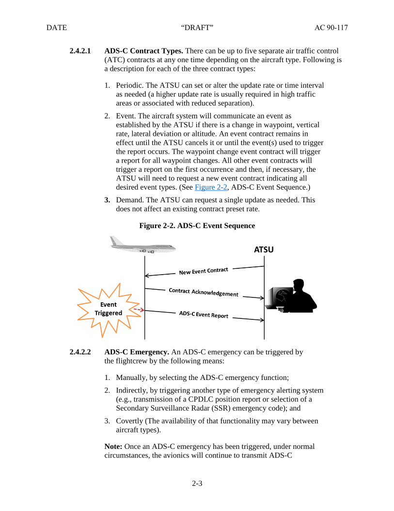
2.4.2.1 ADS-C Contract Types. There can be up to five separate air traffic control (ATC) contracts at any one time depending on the aircraft type. Following is a description for each of the three contract types:
1. Periodic. The ATSU can set or alter the update rate or time intervalas needed (a higher update rate is usually required in high trafficareas or associated with reduced separation).
2. Event. The aircraft system will communicate an event asestablished by the ATSU if there is a change in waypoint, verticalrate, lateral deviation or altitude. An event contract remains ineffect until the ATSU cancels it or until the event(s) used to triggerthe report occurs. The waypoint change event contract will triggera report for all waypoint changes. All other event contracts willtrigger a report on the first occurrence and then, if necessary, theATSU will need to request a new event contract indicating alldesired event types. (See Figure 2-2, ADS-C Event Sequence.)
3. Demand. The ATSU can request a single update as needed. Thisdoes not affect an existing contract preset rate.
Figure 2-2. ADS-C Event Sequence
2.4.2.2 ADS-C Emergency. An ADS-C emergency can be triggered by the flightcrew by the following means:
1. Manually, by selecting the ADS-C emergency function;
2. Indirectly, by triggering another type of emergency alerting system(e.g., transmission of a CPDLC position report or selection of aSecondary Surveillance Radar (SSR) emergency code); and
3. Covertly (The availability of that functionality may vary betweenaircraft types).
Note: Once an ADS-C emergency has been triggered, under normal circumstances, the avionics will continue to transmit ADS-C
2-3

DATE “DRAFT” AC 90-117
emergency periodic reports until the flightcrew de-selects the ADS-C emergency function.
2.5 ATN. ATN is a global internetwork architecture permitting ground, air-ground, and avionics data subnetworks to exchange digital data for the safety of air navigation and for the regular, efficient, and economic operation of ATS. ATN is in limited use in Europe, but not available in the United States National Airspace System (NAS). The system is terrestrial based and not available over oceanic and remote continental areas.
2.5.1 ATN B1. ATN B1 consists of the following data link applications:
• Context management (CM) application for Data Link Initiation Capability (DLIC);
• CPDLC for ATC Communication Management (ACM), ATC Clearance (ACL); and
• ATC Microphone Check (AMC).
2.6 B2. B2 is a future data link communication system planned for global implementation. It harmonizes current implementations of ATN and FANS into a common data link system with additional capabilities. B2 will provide expanded capabilities beyond that available in ATN B1 or FANS 1/A(+) as shown in Table 2-2, Interoperability Designators and Descriptions. It builds on the CPDLC message set used in FANS 1/A(+) and ATN B1, and the ADS-C application used in FANS 1/A(+). B2 will provide additional services such as:
• ADS-C: extended projected profile (EPP); and
• CPDLC: Initial four-dimensional (4-D) trajectory, Dynamic Required NavigationPerformance (DRNP), advanced flight Interval Management (IM).
2.7 Integration of FANS and ATN. Some aircraft integrate FANS and ATN data link systems with various implementations. Aircraft with multiple data link systems incorporate several CPDLC message sets permitting the aircraft to use one system or the other at any given time. Depending on the system used by the ATSU, pilots may be required to logoff one system, then log on to another.
2.8 ACARS ATS. ACARS is a digital datalink system for transmitting short, relatively simple messages between aircraft and ground stations via VHF, HF, or satellite.
1. Background. ARINC designed the ACARS protocol to replace VHF voiceservice in 1978. Later, Societe International de TélécommunicationsAeronautiques (SITA) added additional radio stations to augment this service.Airlines introduced ACARS in the late 1980s to reduce crew workload andimprove data integrity. Although the term ACARS is often thought toencompass only a single data link system installed on the aircraft, it actuallyrefers to a complete air and ground system.
2. Aircraft and Ground ACARS Systems. The aircraft portion of ACARS systemconsists of an avionics computer called an ACARS management unit (MU)
2-4

DATE “DRAFT” AC 90-117
and a control display unit (CDU). On the ground, the ACARS system is made up of a network of radio transceivers to receive (or transmit) datalink messages and route them to various airlines on the network.
3. ACARS ATS supported applications include:
• Departure Clearance (DCL) (not to be confused with CPDLC-DCL),
• Oceanic clearance (OCL),
• Terminal Weather Information for Pilots (TWIP), and
• Digital Automatic Terminal Information Service (D-ATIS).
2.9 Tower Data Link System (TDLS). The TDLS automates tower-generated information for transmission to aircraft via data link communication for both CPDLC-DCL and Pre-Departure Clearance (PDC). The TDLS interfaces with sources of local weather data and flight data in order to provide pilots with PDC, D-ATIS, and CPDLC-DCL services.
Note: The term PDC refers to the U.S. ATS service of ACARS-DCL.
2.10 CPDLC-DCL. CPDLC-DCL is available at various airports in the NAS using FANS 1/A(+) via VDL Mode 0/A and/or Mode 2 for DCL.
2.10.1 Dispatch or Flight Following Systems. For operators with a dispatch center, flight following system, or other base of operations, copies of all data link communications may be routed to, and stored by, the operator. Contact the FAA Data Communications Program Office to coordinate.
2.10.2 Departure Clearance Service (CPDLC-DCL). CPDLC-DCL provides a means for requesting and delivering initial and revised DCLs. These CPDLC messages include departure procedure, flight plan route, initial and requested altitude, beacon code, and departure frequency.
Note 1: CPDLC-DCL is different than international DCL operations. International systems use communication via ARINC 623 ACARS/ European Organization for Civil Aviation Equipment (EUROCAE) ED-85A and not FANS/CPDLC.
Note 2: At participating airports, PDC services may be available for non-FANS equipped aircraft.
2.10.3 CPDLC Specified on the Airport Diagram. To differentiate what communication services are available at each facility, refer to the airport diagram, Standard Instrument Departures (SID), and other terminal procedures pages. See Figure 2-3, Data Link Communication Services on Departure Procedure, for the CPDLC annotation on a departure procedure.
2-5

DATE “DRAFT” AC 90-117
Figure 2-3. Data Link Communication Services on Departure Procedure
2.10.3.1 CPDLC-DCL Logon (See paragraph 5.3). Currently, pilots are expected to log on using the airport identifier (e.g., KJFK for New York Kennedy International). After June 25, 2017, “KUSA” will be the National Single Data Authority (NSDA) for all CPDLC logons in the United States. Pilots activate the data link communication system anytime during preflight by logging on to KUSA with ATC. Within 30 minutes of the proposed departure time, an “ATC Connection Established” message will be received if the following conditions are met:
1. Logon information was correctly formatted;2. An ATC-filed flight plan is on file;
3. Flight plan indicates the aircraft is CPDLC-DCL capable; and
4. ATC controller has approved the DCL.
2.10.3.2 Once a successful ATC connection has been established and the DCL has been approved by the controller, the DCL will be automatically sent to the aircraft. Pilots do not have to request a clearance. After the clearance is received and verified, pilots should:
1. Review the clearance and verify that no clarification from ATC isrequired (Reject/Unable);
2. Confirm the appropriate runway, departure procedure, andtransition with no discontinuities; and then
3. Acknowledge (Accept/Wilco or Reject/Unable) the message.
2-6

DATE “DRAFT” AC 90-117
2.10.3.3 If changes in tower or en route conditions occur (e.g. weather) the ATSU may amend the clearance information and transmit a revised CPDLC-DCL. Pilots should follow the same procedure for revised clearances.
2.11 PDC. PDC is a subscriber based service to provide an effective and efficient means of delivering DCLs prior to taxi. Data link communication technologies are utilized within the NAS to provide a PDC request message from the subscriber’s designated location such as a dispatch center, flight followers, or base of operations to the ATSU. The PDC message is then sent from the ATSU to the operator’s flight operations center (FOC) where it is routed to the flightcrew typically using the following methods:
1. Internet access,
2. Airline gate terminal,
3. Airline operations area terminal,
4. Fixed-Base Operator (FBO) terminal, and
5. ACARS.
2.11.1 OCL. OCLs are delivered via ACARS, similar to a PDC.
2.11.2 PDC Communication. It is not necessary for an aircraft to be equipped with data link communication avionics for a flight to participate in the PDC service. It is only necessary for the flightcrew to be able to obtain a printed copy of the PDC message prior to taxi. The contents of the PDC message are relayed to the aircrew without modification, omission, or alteration. PDC is at the discretion of the clearance delivery controller. If the controller determines that issuing a PDC could introduce confusion, the controller will issue a verbal clearance to the aircrew. If the pilot is uncertain of the clearance, the PDC must not be used and the pilot must contact clearance delivery via voice (telephone or radio) and obtain their clearance.
2.11.3 PDC vs. CPDLC-DCL. The primary difference between the PDC and CPDLC-DCL services is the PDC service depends on the operator or other third party to deliver the PDC to the aircraft whereas CPDLC-DCL service is a direct connection after logon from the tower automation to the flight deck avionics of FANS equipped aircraft. See Table 2-1, PDC vs. CPCLC-DCL, below for a side by side comparison.
2-7

DATE “DRAFT” AC 90-117
Table 2-1. PDC vs. CPDLC-DCL
PDC CPDLC-DCL No logon required Logon Required
Sent to Aeronautical Operational Control (AOC) or other Operator prescribed location
Automatically sent directly to FANS equipped aircraft over data link communication equipment after crew logon
Delivered to the flightcrew by various means (i.e., over ACARS, to the FBO terminal, to the airline gate)
Delivered over data link communication directly to the aircraft
Depending on the delivery method, may require a printed copy to be delivered to the aircraft
Never requires a paper copy to be delivered to the aircraft
Does not require data link communication equipment to be installed in the aircraft
Requires data link communication systems on the aircraft
Does not support revised clearances. Revisions must be transmitted via voice frequency
Revised clearances can be delivered directly to the aircraft when necessary without restrictions
A specific call sign can only be once in an adaptable time period of 12–18 hours at a specific airport
No restrictions
Requires clearance to be manually input in to the flight management system (FMS) by the flightcrew
Clearance can be sent to the avionics system enabling “push to load” via a load prompt
Note: The term DCL used internationally is similar to the term PDC used in the United States.
2.12 Data Authority. “KUSA” will be the NSDA for all NAS CPDLC logons. Figure 2-12, Data Communication Services Strategy, describes the current and planned data communication services to be available in the domestic en route environment. CPDLC en route operations in the NAS will use FANS 1/A(+) equipped aircraft with multi-frequency VDL Mode 2 radios. For an alternate subnetwork, see paragraph 4.5.2.
2.12.1 Current Data Authority (CDA). When an aircraft system accepts a CPDLC connection, this active connection initiates the exchange of messages between the ATSU and the aircraft as the ATSU becomes the CDA. The CDA typically initiates address forwarding to permit a downstream or adjacent ATSU (next data authority (NDA)) to establish an inactive CPDLC connection and/or an Automatic Dependent Surveillance (ADS) contract for monitoring purposes.
2.12.2 NDA. A transfer occurs between the CDA and the NDA when the aircraft CPDLC system terminates the current connection and activates any inactive connection. In this case, the next data authority becomes the CDA and is now able to exchange CPDLC messages with the aircraft. Figure 2-4, Next Data Authority Notification, illustrates the transfer from the CDA to the NDA.
2-8

DATE “DRAFT” AC 90-117
Figure 2-4. Next Data Authority Notification
2.13 ATSUs and Aircraft Interoperability. Figure 2-5, Air Traffic Service Unit (ATSU) and Aircraft Interoperability Designators, shows different ATSU ground systems and interoperable aircraft systems. The diagram shows the CSP and its Centralized ADS-C System (CADS). CSP’s CADS enables an ATSU without FANS 1/A capability to receive ADS-C reports from any FANS 1/A, FANS 1/A(+) or FANS 1/A ADS-C aircraft. A designator is assigned to each type of ATSU and aircraft data link system. Explanations of each interoperability designator are provided below in Table 2-2. Table 2-3, Types of Data Link Systems and Operations, provides an overview of the operational capabilities that are supported by each of the different data link systems.
2-9

DATE “DRAFT” AC 90-117
Figure 2-5. Air Traffic Service Unit (ATSU) and Aircraft Interoperability Designators
2-10

DATE “DRAFT” AC 90-117
Table 2-2. Interoperability Designators and Descriptions
Interoperability Designator Description
ACARS ATS ATS applications, DCL, OCL, TWIP, and D-ATIS supported by ACARS.
Note: The term DCL used internationally is similar to the term PDC used in the United States.
ATSU CADS CSP’s CADS enables an ATSU without FANS 1/A capability to receive ADS-C reports from any FANS 1/A, FANS 1/A(+) or FANS 1/A ADS-C aircraft.
FANS 1/A Initial FANS 1/A ATSU applications, ATSU Facilities Notifications (AFN), CPDLC, and ADS-C supported by FANS 1/A. This AC does not provide an acceptable means of compliance for type design approval for FANS 1/A designated aircraft, but you may use FANS 1/A(+) for new design approvals (see below).
Note: FANS 1/A typically involves communication (CPDLC), navigation (Area Navigation (RNAV)/Required Navigation Performance (RNP)) and surveillance (ADS-C). This document refers to the FANS 1/A for the data link system, which includes the CPDLC and ADS-C applications. Refer to ICAO Doc 9613 for guidance material on navigation (RNAV/RNP) qualification and use.
FANS 1/A ADS-C ATSU applications AFN and ADS-C supported by FANS 1/A. FANS 1/A ADS-C comply with AFN and ADS-C applications, but do not include CPDLC application.
FANS 1/A+ Same as FANS 1/A, except with additional features, such as the message latency timer function, described in DO-258A/ED-100A, paragraph 4.6.6.9.
Note 1: FANS 1/A(+) aircraft is interoperable with FANS 1/A and FANS 1/A(+) ground stations. However, message latency capability is only available when FANS 1/A(+) ground stations interoperates with FANS 1/A(+) aircraft.
Note 2: Seamless transition of ATSU data link service occurs between ATN B1 and FANS 1/A(+) ground stations when:
• Aircraft equipped with ATN B1 and FANS 1/A(+) data linksystem also incorporates interoperability requirement IR-207,IR-209, IR-210, IR-211, IR-212, IR-214, and IR-215 ofDO-305A/ED-154A.
• ATN B1 ground station incorporates interoperability requirementIRec-1 and IR-213 of DO-305A/ED-154A.
• FANS 1/A(+) ground station incorporates interoperabilityrequirement IR-208 of DO-305A/ED-154A.
Otherwise, the flightcrew will lose their data link service requiring the flightcrew to manually perform a logon to reestablish ATSU data link service.
2-11

DATE “DRAFT” AC 90-117
Interoperability Designator Description
Note 3: Seamless transition of ATSU data link service occurs between B2 and FANS 1/A(+) ground stations when:
• Aircraft equipped with B2 and FANS 1/A(+) data link system alsoincorporates interoperability requirement NIR-153, NIR-155,NIR-156, NIR-157, NIR-158, NIR-160, and NIR-161 ofDO-352A/ED-229A.
• B2 ground station incorporates interoperability requirementNIRec-3 and NIR-159 of DO-352A/ED-230A.
• FANS 1/A(+) ground station incorporates interoperabilityrequirement NIR-154 of DO-352A/ED-229A.
Otherwise, the flightcrew will lose their data link service requiring the flightcrew to manually perform a logon to reestablish ATSU data link service.
Note 4: To allow a FANS 1/A(+) data communication system on an aircraft to communicate with an ATN B1 data communication system at an ATSU, the ATSU ground system needs to accommodate the FANS 1/A(+) aircraft by incorporating the interoperability requirements of DO-305A/ED-154A.
Note 5: To allow a FANS 1/A(+) data communication system on an aircraft to communicate with a B2 data communication system at an ATSU, the ATSU ground system needs to accommodate the FANS 1/A(+) aircraft by incorporating the interoperability requirements of DO-352A/ED-230A.
ATN B1 ATS applications CM and CPDLC supported by ATN B1:
a) CM is a data link application providing DLIC.
b) CPDLC (Version 1) for ACM, ACL, and AMC.
Note 1: Interoperability for DCL, downstream clearance (DSC), D-ATIS, and flight plan consistency (FLIPCY) data link services, which are defined in DO-280B/ED-110B are not supported.
Note 2: Seamless transition of ATS data link service between ATN B1 and FANS 1/A+ ground stations when:
• Aircraft equipped with ATN B1 and FANS 1/A+ data linksystem also incorporates interoperability requirement IR-207,IR-209, IR-210, IR-211, IR-212, IR-214, and IR-215 ofDO-305A/ED-154A.
• ATN B1 ground station incorporates interoperability requirementIRec-1 and IR-213 of DO-305A/ED-154A.
• FANS 1/A+ ground station incorporates interoperabilityrequirement IR-208 of DO-305A/ED-154A.
Otherwise, the flightcrew will lose their service requiring the flightcrew to manually perform a logon to reestablish ATS data link service.
2-12

DATE “DRAFT” AC 90-117
Interoperability Designator Description
Note 3: To allow a FANS 1/A+ data communication system on an aircraft to communicate with an ATN B1 data communication system at an ATSU, the ATSU ground system needs to accommodate the FANS 1/A+ aircraft by incorporating the interoperability requirements of DO-305A/ED-154A.
Note 4: To allow an ATN B1 data communication system on an aircraft to communicate with a B2 data communication system at an ATSU, the ATSU ground system needs to accommodate the ATN B1 aircraft by incorporating the interoperability requirements of DO-353A/ED-231A.
Note 5: To allow a B2 data communication system on an aircraft to communicate with an ATN B1 data communication system at an ATSU, the B2 data communication system on the aircraft needs to accommodate the ATN B1 ground system by incorporating the interoperability requirements of DO-353A/ED-231A.
B2 Version of the Baseline 2 Data Communication system described in this section. The United States plans to use B2, as defined in this AC, as part of FAA’s NextGen initiative. An aircraft equipped with B2, as defined in this AC, is fully interoperable with any B2 ground station. Aircraft equipped with a version of B2 other than that defined by this AC are not eligible for the B2 interop designator. B2 is comprised of the following data link applications and data link services.
a) CM is a data link application supporting the following data linkservice: DLIC.
b) CPDLC (Version 3) is a data link application supporting thefollowing data link services: ACM, Clearance Request and Delivery (CRD), AMC, DCL, Data Link Taxi (D-TAXI), Oceanic Clearance Delivery (OCD), 4-D Trajectory Data Link (4DTRAD), Information Exchange and Reporting (IER), In-Trail Procedures (ITP), IM, and DRNP.
c) ADS-C (Version 2) is a data link application supporting thefollowing data link services: 4DTRAD, IER, Position Reporting (PR), IM, and DRNP.
Note 1: To allow a FANS 1/A+ data communication system on an aircraft to communicate with a B2 data communication system at an ATSU, the ATSU ground system needs to accommodate the FANS 1/A+ aircraft by incorporating the interoperability requirements of DO-352A/ED-230A.
Note 2: To allow an ATN B1 data communication system on an aircraft to communicate with a B2 data communication system at an ATSU, the ATSU ground system needs to accommodate the ATN B1 aircraft by incorporating the interoperability requirements of DO-353A/ED-231A.
2-13

DATE “DRAFT” AC 90-117
Interoperability Designator Description
Note 3: To allow a B2 data communication system on an aircraft to communicate with an ATN B1 data communication system at an ATSU, the B2 data communication system on the aircraft needs to accommodate the ATN B1 ground system by incorporating the interoperability requirements of DO-353A/ED-231A.
2-14

DATE “DRAFT” AC 90-117
Table 2-3. Types of Data Link Systems and Operations
Aircraft Equipment and
Capability
ACARS ATS (ATSU Ground
Data Link System)
CADS or AOC
(ATSU Ground Data Link System)
FANS 1/A (ATSU Ground
Data Link System)
ATN B1 (ATSU Ground
Data Link System)
FANS 1/A– ATN B1
(ATSU Ground Data Link System)
ACARS ATS ATC communication • DCL or PDC• OCL Flight
information• D-ATIS
N/A N/A N/A N/A
FANS 1/A ADS-C
N/A Surveillance • ADS-C
(CADS)
Surveillance • ADS-C
N/A N/A
FANS 1/A N/A Surveillance • ADS-C
(CADS)
ATC communication • CPDLC
Surveillance• ADS-C
N/A ATC communication • CPDLC for
ACM, ACL,and AMCdata linkservices
FANS 1/A+ N/A Surveillance • ADS-C
(CADS)
ATC communication • CPDLC
Surveillance• ADS-C
N/A ATC communication • CPDLC for
ACM, ACL,and AMCdata linkservices
ATN B1 N/A N/A N/A ATC communication • CPDLC for
ACM, ACL,and AMCdata linkservices
ATC communication • CPDLC for
ACM, ACL,and AMCdata linkservices
FANS 1/A– ATN B1
N/A Surveillance • ADS-C
(CADS)
ATC communication • CPDLC
Surveillance• ADS-C
ATC communication • CPDLC for
ACM, ACL,and AMCdata linkservices
ATC communication • CPDLC for
ACM, ACL,and AMCdata linkservices
2-15
DATE “DRAFT” AC 90-117
2.14 Performance-Based Communication and Surveillance (PBCS) Concept. The PBCS concept provides objective operational criteria to evaluate different and emerging communication and surveillance technologies are intended for evolving Air Traffic System Management (ATM) operations. Once these criteria have been set and accepted, a specific implementation of an ATM operation including its technical and human performance may have its viability assessed against these operational criteria. The PBCS concept and the guidelines provided in this AC are applicable to any ATS system change based on communication and/or surveillance performance.
2.14.1 Aligned with Performance-Based Navigation (PBN). The PBCS concept is aligned with the concept of PBN. While the PBN concept applies RNP and RNAV specifications to the navigation element, the PBCS concept applies required communication performance (RCP) and required surveillance performance (RSP) specifications to communication and surveillance elements, respectively. Each RCP/RSP specification includes allocated criteria among the components of the communication and surveillance systems involved.
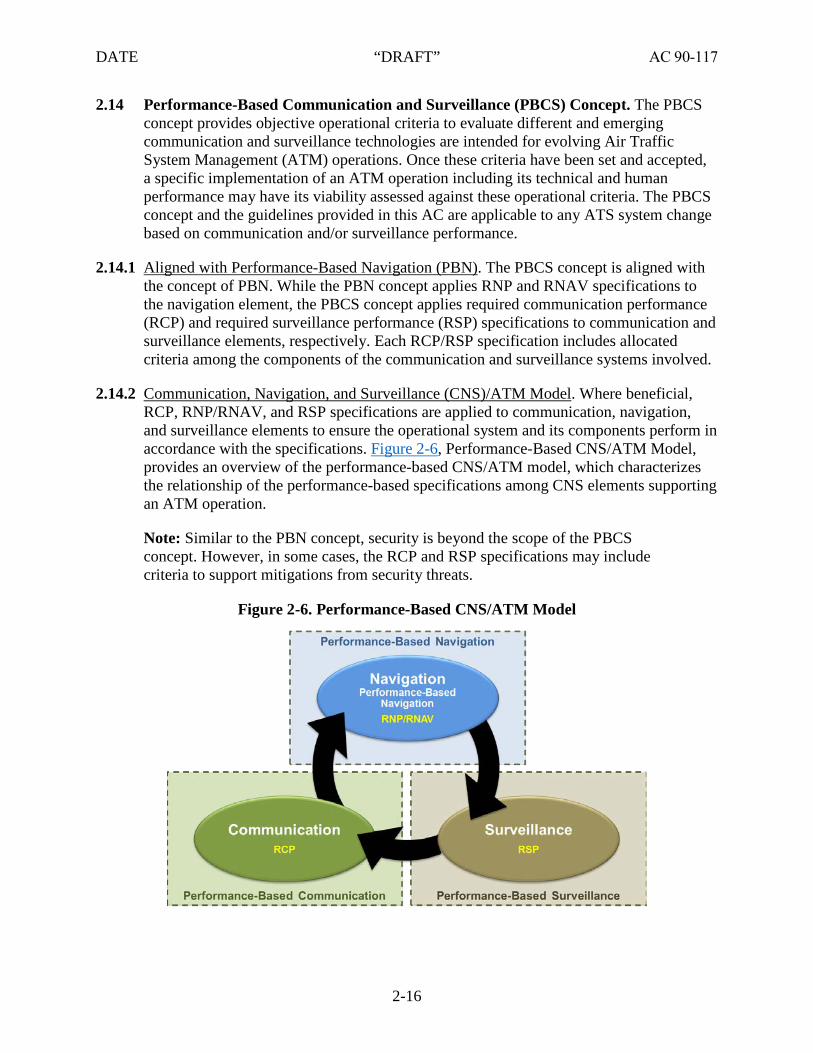
2.14.2 Communication, Navigation, and Surveillance (CNS)/ATM Model. Where beneficial, RCP, RNP/RNAV, and RSP specifications are applied to communication, navigation, and surveillance elements to ensure the operational system and its components perform in accordance with the specifications. Figure 2-6, Performance-Based CNS/ATM Model, provides an overview of the performance-based CNS/ATM model, which characterizes the relationship of the performance-based specifications among CNS elements supporting an ATM operation.
Note: Similar to the PBN concept, security is beyond the scope of the PBCS concept. However, in some cases, the RCP and RSP specifications may include criteria to support mitigations from security threats.
Figure 2-6. Performance-Based CNS/ATM Model
2-16

DATE “DRAFT” AC 90-117
2.14.3 PBCS and PBN Differences. There are some differences between the PBCS concept and PBN concept:
1. The PBCS concept applies RCP and RSP specifications, which allocatecriteria to ATS provision, including communication services, aircraftcapability, and the aircraft operator. The PBN concept applies RNP/RNAVspecifications which allocate criteria only to the aircraft capability and theaircraft operator; and
2. The PBCS concept includes post-implementation monitoring programs, on alocal and regional basis, with global exchange of information. The PBNconcept includes real-time monitoring and alerting functionality in the aircraftcapability.
Note: PBCS includes real-time alerts (e.g., when a communication transaction expires or a position report is overdue) that are conceptually different than the PBN alerts (e.g., RNP UNABLE).
2.15 RCP and RSP Specifications Supporting ATM Operations. To perform ATM operations within a performance-based airspace, the standards specify functional, safety and performance criteria for the applicable CNS elements. RCP and RSP specifications, in conjunction with RNP/RNAV specifications, provide these criteria and are intended to facilitate the development of standards for ATM operations. This approach is essential to the evolution of operational concepts that use emerging technologies.
2.15.1 RCP Specifications. An RCP specification represents operational parameters for the complete communication transaction time in seconds (e.g., RCP 240). These specifications are a set of requirements for ATS provision and associated ground equipment, aircraft capability, and operations needed to support performance-based communication. Communication performance requirements are included and allocated to system components. The functionality includes transaction time, continuity, availability, integrity, and safety. RCP specifications are applied to achieve the performance required of the communication process and may support aircraft separation minima. To view current oceanic RCP specifications applicable to oceanic and remote continental operations, see Table 2-3 and Table 2-6, RCP 240 Integrity Criteria (Aircraft System).
2.15.2 RCP Parameters. The following describes the RCP parameters:
• RCP Transaction Time. The maximum time for the completion of the operationalcommunication transaction after which the initiator should revert to an alternativeprocedure;
• RCP Continuity (RCP C). The minimum proportion of operational communicationtransactions to be completed within the specified RCP transaction time, given theservice was available at the start of the transaction;
2-17

DATE “DRAFT” AC 90-117
• RCP Availability. The required probability that an operational communicationtransaction can be initiated; and
• RCP Integrity (RCP I). The required probability that an operational communicationtransaction is completed with no undetected errors.
Note: While RCP I is defined in terms of the “goodness” of the communications capability, it is specified in terms of likelihood of occurrence of malfunction on a per flight hour basis (e.g., 10-5), consistent with RNAV/RNP specifications.
Figure 2-7. Actual Communications Performance (ACP)
2.15.3 RCP Framework and Actual Communication Performance (ACP). In Figure 2-7, Actual Communications Performance (ACP), the combined uplink and downlink performance of ground systems, communication service, and aircraft systems is the Actual Communication Technical Performance (ACTP). Pilots and controllers should respond as soon as possible as part of the overall human performance. Human performance combined with ACTP results in the ACP. ACP is an indicator of the operational performance of a communication system which includes the human and technical components. Human performance considers such factors as training, procedures, and human-machine interface (HMI). Technical performance comprises the installed elements of communication performance operating together to meet the intended function. ACP is assessed in the same terms and parameters as an RCP specification, its allocations, and other relevant operational criteria provided by an RCP specification.
2-18

DATE “DRAFT” AC 90-117
Operationally, an appropriate level of communication performance is required for aircraft systems, communications networks, and ground systems.
Note: In ICAO documentation, pilot response time is called Pilot Operational Response Time (PORT).
Figure 2-8. RCP 240 Illustration
2.15.4 RCP 240 Illustration. As illustrated in Figure 2-8, RCP 240 Illustration, the controller sends a data link communication message through the ATSU via the CSP to the aircraft. The Required Communication Technical Performance (RCTP) is the overall time for the communication to travel from the ATSU to the flight deck and return excluding human response time. RCTP should be less than or equal to 150 seconds for 99.9 percent of the time (operational) and must be less than or equal to 120 seconds for 95 percent of the time (nominal). The message arrives at the flight deck and the pilot should respond as soon as possible (i.e., Accept/WILCO, Reject/Unable, or Standby). The pilot responds to the message and it travels back to the ATSU.
2.15.5 RCP 240 Specification Tables. Table 2-4, RCP 240 Transaction Time and Continuity Allocations–CPDLC, shows Transaction Time and Continuity allocations from the sender (controller) to (responder (pilot) and back to sender (controller). RCTP consists of the ATSU system, network, and the aircraft system. Table 2-5, RCP 240 Availability Criteria
2-19

DATE “DRAFT” AC 90-117
(Aircraft System), provides the aircraft system availability criteria. Table 2-6, RCP 240 Integrity Criteria (Aircraft System), provides the integrity criteria for the aircraft system.
Table 2-4. RCP 240 Transaction Time and Continuity Allocations—CPDLC
RCTP Controller ATSU system
Network Aircraft system
Pilot Response
Aircraft system
Network ATSU system
Controller RCTP
99.9% PC/ATSU (30) PATSU(15) PNET(120) PAIR(15) 60 PAIR(15) PNET(120) PATSU(15) PC/ATSU (30) 99.9%
95% PC/ATSU (30) PATSU(10) PNET(100) PAIR(10) 60 PAIR(10) PNET(100) PATSU(10) PC/ATSU (30) 95%
Table 2-5. RCP 240 Availability Criteria (Aircraft System)
Availability Parameter Efficiency Safety Compliance Means
Availability – aircraft (AAIR) N/A 0.999 Analysis, architecture, design, pre implementation demonstration
Table 2-6. RCP 240 Integrity Criteria (Aircraft System)
Integrity Parameter Integrity Value Compliance Means
Integrity (I) Malfunction = 10-5 per flight hour
Analysis, safety requirements, development assurance level (e.g. Level C software) commensurate with integrity level, pre-implementation demonstration.
2-20

DATE “DRAFT” AC 90-117
Figure 2-9. RCP 400 Illustration
2.15.6 RCP 400 Illustration. As illustrated in Figure 2-9, RCP 400 Illustration, the controller sends a data link communication message through the ATSU through the CSP to the aircraft. The RCTP is the overall time for the communication to travel from the ATSU to the flight deck and return excluding human factors. RCTP should be less than or equal to 310 seconds for 99.9 percent of the time (operational) and must be less than or equal to 260 seconds for 95 percent of the time (nominal). The message arrives at the flight deck and the pilots should respond as soon as possible (i.e., Accept/WILCO, Reject/Unable, or Standby). The pilot responds to the message and it travels back to the ATSU.
2.15.7 RCP 400 Transaction Time and Continuity Criteria. Table 2-7, RCP 400 Transaction Time and Continuity Allocations—CPDLC, shows Transaction Time and Continuity allocations from the sender (controller) to (responder (pilot) and back to sender (controller). RCTP consists of the ATSU system, network, and the aircraft system. Table 2-8, RCP 400 Availability Criteria (Aircraft System), provides the availability criteria for the aircraft system. Table 2-9, RCP 240 Integrity Criteria (Aircraft System), provides the integrity criteria for the aircraft system.
2-21

DATE “DRAFT” AC 90-117
Table 2-7. RCP 400 Transaction Time and Continuity Allocations—CPDLC
RCTP Controller ATSU system
Network Aircraft system
Pilot Response
Aircraft system
Network ATSU system
Controller RCTP
99.9% PC/ATSU (30) PATSU(15) PNET(280) PAIR(15) 60 PAIR(15) PNET(280) PATSU(15) PC/ATSU (30) 99.9%
95% PC/ATSU (30) PATSU(10) PNET(240) PAIR(10) 60 PAIR(10) PNET(240) PATSU(10) PC/ATSU (30) 95%
Table 2-8. RCP 400 Availability Criteria (Aircraft System)
Availability Parameter Efficiency Safety Compliance Means
Availability – aircraft (AAIR) N/A 0.999 Analysis, architecture, design, pre implementation demonstration
Table 2-9. RCP 240 Integrity Criteria (Aircraft System)
Integrity parameter Integrity value Compliance means
Integrity (I) Malfunction = 10-5 per flight hour
Analysis, safety requirements, development assurance level (e.g. Level C software) commensurate with integrity level, pre-implementation demonstration.
2.16 Required Surveillance Performance (RSP).
2.16.1 Background. In the past, surveillance over oceanic and remote continental areas was limited to pilot position reports via HF radio. When crossing a compulsory reporting point, the pilot would contact the ATSU via a radio operator and report: identification, position, time, altitude, next PR point, name of succeeding reporting point, and remarks. Once the aircraft entered a radar environment, pilot reports were eliminated. Today, along with voice pilot position reports, surveillance in oceanic and remote continental airspace is accomplished much more accurately through the use of ADS-C. As with CPDLC, ADS-C requires certain performance requirements for operational surveillance in support of specific ATM functions. This includes the transmission of aircraft position, velocity and intent with a specified precision, accuracy and update rates. In combination with RCP and RNP, RSP enables the efficient use of airspace by allowing reduced lateral and along-track separation of aircraft by supplying accurate and frequent updates of aircraft position.
2.16.2 RSP Concept. The concept of RSP relates to the surveillance component and complements RNP and RCP. A collective set of performance measures are established to ensure overall communication transactions are suitable for certain surveillance related goals. For example, the surveillance goal may be to achieve 30 nautical miles (NM)
2-22

DATE “DRAFT” AC 90-117
lateral and 30 NM along-track separation in oceanic airspace. RSP is operationally derived and not based on any specific techniques, aircraft technologies, or architecture.
2.16.3 RSP Specification. An RSP specification is identified by a designator (e.g., RSP 180) in order to simplify the designator naming convention and to make the RSP Data Delivery Time (DT) readily apparent to airspace planners, aircraft manufacturers and operators. The designator represents the value for the surveillance data delivery time when the surveillance data delivery is considered overdue. RSP specifications are applied to airspace based on specific objectives. For example, the performance required of the surveillance process used to support particular separation minima. An RSP specification is a label (e.g., RSP 180) represents the values assigned to RSP parameters for surveillance transaction time (in seconds), continuity, availability, and integrity. A specified RSP specification is intended to define the surveillance performance required of a surveillance process to support a particular ATM function. RSP specification is applied to the airspace, route, or procedure based on the most stringent RSP specification of the required ATM functions.
2.16.4 RSP Parameters. RSP include the accuracy of the reported position, the latency in reporting the position to the controller, and the integrity, availability, and continuity of the surveillance data. The following describes the RSP parameters:
1. RSP Surveillance Data Transit Time. The maximum time for the reception ofthe surveillance data after which the controller should revert to an alternativeprocedure.
2. RSP Continuity. The minimum proportion of surveillance data delivery to becompleted within the specified RSP surveillance data delivery time, given theservice was available at the start of the delivery.
3. RSP Availability. The required probability that surveillance data can beprovided.
4. RSP Integrity. The required probability that surveillance data delivery iscompleted with no undetected errors.
2-23

DATE “DRAFT” AC 90-117
Figure 2-10. RSP 180 Illustration
2.16.5 RSP 180 Illustration. In Figure 2-10, RSP 180 Illustration, the ATSU establishes an event contract with the aircraft with specific allocations described below:
1. From 1 to 2 (Aircraft). The aircraft reaches the particular event and is requiredto respond within 5 seconds or less 99.9 percent of the operational time andless than or equal to 3 seconds 95 percent of the nominal time.
2. From 2 to 3 (CSP). The signal is then transmitted through the communicationservice provider (CSP) network. This action must occur within 170 seconds orless for 99.9 percent of the operational time and less than or equal to84 seconds 95 percent of the nominal time.
3. From 3 to 4 (ATSU). From the (CSP) this message is sent through the ATSUwhich has a required performance of less than or equal to 5 seconds for99.9 percent of the time and less than or equal to 3 seconds for 95 percent ofthe time. The total communication from the event to the controller must beless than or equal to 180 seconds with 99.9 percent probability (operational)and less than or equal to 90 seconds with 95 percent probability (nominal).
2.16.6 RSP 180 Specification Tables. Table 2-10, RSP 180 Surveillance Data Delivery and Continuity Allocations—ADS-C, shows allocations for Required Surveillance Monitoring Performance/Required Surveillance Technical Performance (RSMP/RSTP) consisting of the aircraft system, network and ATSU. Table 2-11, RSP 180 Availability Criteria (Aircraft System), provides the availability criteria for the aircraft system.
2-24

DATE “DRAFT” AC 90-117
Table 2-12, RSP 180 Integrity Criteria (Aircraft System) provides the integrity criteria for the aircraft system.
Table 2-10. RSP 180 Surveillance Data Delivery and Continuity Allocations—ADS-C
RSMP/RSTP Aircraft system Network ATSU RSMP/RSTP
99.9% 5 170 5 99.9%
95% 3 84 3 95%
Table 2-11. RSP 180 Availability Criteria (Aircraft System)
Availability Parameter Efficiency Safety Compliance Means
Availability – aircraft (AAIR) N/A 0.999 Analysis, architecture, design, pre implementation demonstration
Table 2-12. RSP 180 Integrity Criteria (Aircraft System)
Integrity parameter Integrity value Compliance means
Integrity (I) Malfunction = 10-5 per flight hour
Analysis, safety requirements, development assurance level (e.g. Level C software) commensurate with integrity level, pre-implementation demonstration. See also related safety requirement SR-26 for the aircraft system.
2-25
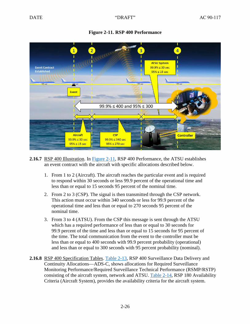
DATE “DRAFT” AC 90-117
Figure 2-11. RSP 400 Performance
2.16.7 RSP 400 Illustration. In Figure 2-11, RSP 400 Performance, the ATSU establishes an event contract with the aircraft with specific allocations described below.
1. From 1 to 2 (Aircraft). The aircraft reaches the particular event and is requiredto respond within 30 seconds or less 99.9 percent of the operational time andless than or equal to 15 seconds 95 percent of the nominal time.
2. From 2 to 3 (CSP). The signal is then transmitted through the CSP network.This action must occur within 340 seconds or less for 99.9 percent of theoperational time and less than or equal to 270 seconds 95 percent of thenominal time.
3. From 3 to 4 (ATSU). From the CSP this message is sent through the ATSUwhich has a required performance of less than or equal to 30 seconds for99.9 percent of the time and less than or equal to 15 seconds for 95 percent ofthe time. The total communication from the event to the controller must beless than or equal to 400 seconds with 99.9 percent probability (operational)and less than or equal to 300 seconds with 95 percent probability (nominal).
2.16.8 RSP 400 Specification Tables. Table 2-13, RSP 400 Surveillance Data Delivery and Continuity Allocations—ADS-C, shows allocations for Required Surveillance Monitoring Performance/Required Surveillance Technical Performance (RSMP/RSTP) consisting of the aircraft system, network and ATSU. Table 2-14, RSP 180 Availability Criteria (Aircraft System), provides the availability criteria for the aircraft system.
2-26

DATE “DRAFT” AC 90-117
Table 2-15, RSP 180 Integrity Criteria (Aircraft System), provides the integrity criteria for the aircraft system.
Table 2-13. RSP 400 Surveillance Data Delivery and Continuity Allocations—ADS-C
RSMP/RSTP Aircraft system Network ATSU RSMP/RSTP
99.9% 30 340 30 99.9%
95% 15 270 15 95%
Table 2-14. RSP 180 Availability Criteria (Aircraft System)
Availability Parameter Efficiency Safety Compliance Means
Availability – aircraft (AAIR) N/A 0.999 Analysis, architecture, design, pre implementation demonstration
Table 2-15. RSP 180 Integrity Criteria (Aircraft System)
Integrity parameter Integrity value Compliance means
Integrity (I) Malfunction = 10-5 per flight hour
Analysis, safety requirements, development assurance level (e.g. Level C software) commensurate with integrity level, pre-implementation demonstration. See also related safety requirement SR-26 for the aircraft system.
2.17 High Frequency Data Link (HFDL). Over the past few decades HF has provided an effective means of voice communication over long distance in oceanic and remote continental airspace. HF communication is no longer restricted to voice and provides another means of sending and receiving digital communication. HFDL augments existing VHF and satellite communications (SATCOM) (i.e., CPDLC and ADS-C) data link communication systems. A subnetwork of 15 HFDL ground stations extends worldwide communication coverage beyond that of VHF data link communication subnetworks.
2.17.1 HFDL Applications. HFDL network provides communication to both ATSU and AOC in oceanic and remote continental airspace and can be used for:
1. Non-SATCOM equipped aircraft with a long-range, cost-effective data linkcommunication capability,
2. Data link communication in polar regions where geostationary satelliteconnections may not exist or be degraded, and
3. A back-up means of data link communication for SATCOM (CPDLC andADS-C) equipped aircraft.
2-27

DATE “DRAFT” AC 90-117
2.17.2 Ionosphere HF Disturbance and Reliability. HF is subject to temporary signal distortion due to changes in the ionosphere layer shape and density. Because of multiple HFDL ground stations, ionosphere disturbances are less frequent than in the early days of HF voice. Modern aircraft HFDL systems automatically search for the best available frequency from all HFDL operational ground station frequencies. Once a suitable frequency is found, the aircraft establishes a connection by sending a logon message to the ground station. A logon confirmation uplink is established enabling the pilot to send data.
Note: Monitoring data have shown that HFDL does not meet RCP 240/RSP 180.
2.18 Future NAS Data Link Communication Services. Figure 2-12 depicts future plans for data link communication services. Though this planning diagram is subject to change, it generally provides a preview of expanding data link services in the next few years. This is added to the AC to enable operators planning upgrades in pace with future technology and upcoming data link communication services.
Figure 2-12. Data Communication Services Strategy
2-28

DATE “DRAFT” AC 90-117
2.19 Data Communication Services Strategy. Segment 1 in Figure 2-12 consists of two phases:
1. Tower Services and En Route Services. Segment 1, Phase 2 (S1P2) serviceswill be delivered in two stages, “initial” services and “full” services.S1P2 en route services is expected to begin in 2019 and is planned to leverageexisting Phase 1 FANS 1/A aircraft and expand Phase 1 infrastructure todeliver CPDLC services in the United States NAS en route airspace.
2. Full En Route Services. Full en route services is expected to begin in 2025,will require upgrades to aircraft and infrastructure to provide advancedservices, such as 4-D trajectories, DRNP, advanced flight IM with ATC windinformation and data link communication – taxi clearances (D-TAXI).The following paragraphs describe some full service features.
Note: The full services of speed, stuck microphone, adapted arrivals, and beacon codes are deferred until further notice.
2.19.1 Speeds.
1. Initial Services. The controller can issue UM61 CROSS (position) AT ANDMAINTAIN (altitude) AT (speed).
2. Full Services (Deferred). The controller will be able to:
• Issue speed clearance providing the flightcrew with instructions to maintain aspeed in Mach number or indicated airspeed,
• Assign speeds of greater than or less than specific values, and
• Instruct the flightcrew to resume normal speed or to maintain present speed.The flightcrew will be able to request a speed clearance.
2.19.2 Crossing Restrictions. Initially, the controller will be able to use two crossing restriction message elements to instruct the flightcrew to cross a specific fix at a specific altitude and, if desired, at a specific speed. With full service, the controller will have considerably more flexibility in composing crossing restriction clearances. For example, the controller will be able to clear an aircraft to cross a specific fix at a specific time and have the option of entering a crossing restriction.
2.19.3 Routes. Initially, the flightcrew will be able to REQUEST DIRECT TO (position). The controller will be able to issue route clearances, such as PROCEED DIRECT TO (position), CLEARED TO (position) VIA (route clearance), CLEARED (route clearance), and AT (position) CLEARED (route clearance). With full service, the controller’s workstation will be enhanced to support entry from the Radar (R) and Radar Associate (RA) positions and permit entry of route offsets with additional message elements.
2.19.4 Advisory. Air Traffic personnel issue advisory messages to aircraft on a routine basis. Examples include dynamic airport information (runway closures, runway visual range,
2-29

DATE “DRAFT” AC 90-117
braking action, etc.), convective significant meteorological information (SIGMET), Central Weather Advisories (CWA), Pilot Weather Reports (PIREP), weather displayed on the controller’s scope, and current ride reports. CPDLC will allow the controller to send a limited set of advisory messages to the aircraft on a case-by-case basis or to all aircraft with which the controller has a CPDLC connection. Advisory messages such as SIGMETs and CWAs, which must be broadcast to all aircraft on frequency, will still need to be verbally broadcast in a mixed equipage environment. However, advisory messages that are issued to individual aircraft, such as dynamic airport information, displayed weather, PIREPS, and current ride reports are excellent candidates for automating. S1P2 CPDLC services will only support ride reports and free text messages created at the sector. The messages will be provided to the controller to send to the appropriate aircraft. In addition to freeing the controller from verbally delivering the advisory, CPDLC also allows positive confirmation that affected aircraft have received the information.
2.19.5 Holding Instructions. The controller may be directed to hold all arrivals for a particular airport. When this occurs, the controller uses the modified RA-position holding menu or a keyboard entry at either the Radar (R) or RA position to issue a clearance to hold at a specific fix on the cleared route of flight. With full service, the controller will be able to send a CPDLC message HOLD AT (position) MAINTAIN (altitude) INBOUND TRACK (degrees) (direction) TURN LEG TIME (leg type). The controller will also be able to combine this message with another message indicating when to expect further clearance at a specified time to the aircraft.
2.19.6 Stuck Microphone (deferred). With full service, the controller will be able to instruct the flightcrew to check their microphones.
2.19.7 Adapted Arrivals (deferred).With full service, the controller and flightcrew will be able to use CPDLC to execute adapted arrival procedure. The adapted procedure contains both lateral and vertical aircraft maneuvers and provides greater efficiency for users.
2.19.8 Beacon Codes (deferred). As aircraft transition in the NAS from one facility to another, there is the possibility of beacon code duplication. Often this happens when there is significant traffic and/or delays in the system. It is also prevalent at facilities which border foreign airspace. Today, when this conflict occurs, En Route Automation Modernization (ERAM) will assign the aircraft a new code and notify the controller, who then verbally issues it to the pilot. With CPDLC, the FAA ground system will automatically send a UM with the new code to the aircraft at the appropriate time with no controller involvement. The controller will also be able to manually compose and send a beacon code message if needed.
2-30

DATE “DRAFT” AC 90-117
CHAPTER 3. AIRCRAFT ELIGIBILITY
3.1 Introduction. This chapter provides guidance on how operators can determine if their aircraft data link system is compliant and eligible for operational use. This AC does not address design approval or installation of data link systems. For airworthiness guidance, refer to AC 20-140( ), Guidelines for Design Approval of Aircraft Data Link Communication Systems Supporting Air Traffic Services (ATS).
3.2 Aircraft Eligibility. The Airplane Flight Manual (AFM) should identify the following for data link communication eligibility:
1. Interoperability,
2. Subnetwork, and
3. Aircraft performance.
Note: Descriptions of the data link services are provided for a given airspace or operation. For example, in the United States, departure clearance (Controller-Pilot Data Link Communication—Departure Clearance (CPDLC-DCL)) service requires the aircraft to be interoperable with Future Air Navigation Systems (FANS)-1/A, to use either the Very High Frequency (VHF) Data Link (VDL) Mode 0/A or VDL Mode 2 subnetwork, and to not have any prescribed aircraft performance requirements. Operators should refer to the requirements defined by the Air Traffic Service Unit (ATSU) for each operation. A summary of typical operational requirements is provided in Chapter 5 of this AC.
3.3 Statement of Compliance (SOC). Due to the complexity of the criteria to determine eligibility, the operator must obtain a statement of compliance from the entity that owns the design approval for their data link installation. This may be the aircraft manufacturer, the operator, the manufacturer of the data link system, or another party. The statement of compliance should be provided in the normal section of the AFM or AFM supplement. Table C-3, Preferred Original Equipment Manufacturer Annotation, provides an example of a statement of compliance. The statement of compliance should indicate the aircraft data link system meets the aircraft-allocated requirements of Required Communication Performance (RCP) and Required Surveillance Performance (RSP) specifications contained in the AFM.
3.3.1 Interoperability. The operator should confirm the interoperability of their aircraft data link system (interoperability requirements standards (INTEROP) designators are described in Table 2-2, Interoperability Designators and Descriptions).The statement of compliance should indicate the INTEROP and a reference to the definition of that INTEROP. Aircraft Communications Addressing and Reporting System (ACARS) ATS, FANS 1/A, FANS 1/A+, and Aeronautical Telecommunications Network (ATN) Baseline 1 (B1) INTEROP designators, and/or the compliance statement, should reference AC 20-140 or later revision. For the ATN Baseline 2 (B2) INTEROP designator, the compliance statement should reference AC 20-140C or later revision. For en route National Airspace System (NAS) operations, the avionics system must have
3-1

DATE “DRAFT” AC 90-117
“push to load” capability into the navigation system whenever a routing change is received for operations supported by B2 and FANS 1/A(+) data link communication systems.
3.3.2 Subnetwork. The operator should confirm the subnetwork capability of their aircraft (subnetworks are described in paragraph 2.2.1). The statement of compliance should indicate the subnetworks that are supported and a reference to the definition of the subnetworks. The compliance statement should reference AC 20-140 or later for any of the following subnetworks:
• VDL M0/A,
• VDL M2,
• High Frequency Data Link (HFDL),
• Satellite communications (SATCOM) International Maritime Satellite Organization(INMARSAT) (Classic Aero), and
• SATCOM Iridium (Short Burst Data (SBD)).
Note: For aircraft utilizing SATCOM INMARSAT (Swift Broadband (SBB)), the SOC should reference AC 20-140C or later.
3.3.3 VDL M2 Requirements for En Route NAS. The VDL M2 requirements include aircraft that are equipped with VDL Mode 2 radios approved to Technical Standard Order (TSO)-C160a or later.
Note 1: Minimum performance standard of TSO-C160 does not include the capability for the radio to be tuned to more than one VDL M2 channel (i.e., only capable of being tuned to 136.975 MHz).
Note 2: The FAA accepts the use of VDL M0/A en route when VDL M2 communications are lost, if the aircraft is equipped with a properly functioning VDL M2 radio before starting the flight or dispatching. An alternate subnetwork may be used provided it complies with paragraph 4.5.2. Table C-1, Summary Airspace Requirements, provides a summary of airspace requirements.
3.3.4 Performance Data for Compliance. The operator should evaluate the demonstrated performance of their aircraft data link system. Actual Communications Performance (ACP) of the CPDLC two-way communications and Actual Surveillance Performance (ASP) of the Automatic Dependent Surveillance-Contract (ADS-C) are evaluated against respective RCP and RSP specification standards. This data should be included to quantify support of the aircraft performance portion of the data link eligibility. If no performance data is available, then initial compliance for applicable airspace will be based on the SOC with performance being monitored as data is collected. (See Chapter 6.)
Note: For fleet aircraft, records for every tail number are not necessary provided that all the aircraft have the same data link communication configuration.
3-2

DATE “DRAFT” AC 90-117
Operators with a single aircraft may meet the above requirement using records of other aircraft with the same make, model, and series (M/M/S) and the same data link communication configuration.
3.4 Configuration Control. Operators should maintain their aircraft in an avionics configuration which has been shown to provide acceptable data link communication performance.
Note: If the Electronic Flight Bag (EFB) is integrated with the aircraft’s data link systems, review documented procedures for updating the EFB.
3.5 Maintenance. The operator is responsible for all maintenance of data link communication systems. Maintenance procedures for data link communications are approved or accepted as part of an operator’s initial maintenance manual approval or as a revision to that manual.
Note: Maintenance facilities conducting Supplemental Type Certificate (STC) modifications must coordinate Master Minimum Equipment List (MMEL)/minimum equipment list (MEL) changes that include all data communications equipment with the Aircraft Evaluation Group (AEG).
3.5.1 System Alteration (Including Software Updates). Operators must evaluate alterations to the aircraft and identify any changes to aircraft eligibility. The owner of the design approval for the alteration must confirm the alteration did not affect the data link system. If the alteration affected the data link system, the owner of the design must provide a statement of compliance to the associated INTEROP, subnetworks and performance standards. Operators must determine aircraft eligibility after each alteration.
3.5.2 Subnetwork Configuration for Route Coverage. The operator must ensure communication coverage capability of their aircraft’s subnetwork for the route to be flown (see paragraph 4.1.2). For adequate coverage, operators may have to adjust their aircraft’s media management parameters (e.g., where the system automatically switches from VDL to SATCOM). Operators have experienced unacceptable performance transitioning airspace with marginal VDL coverage because the aircraft tries to maintain or reestablish a VDL connection. Some States may also limit the subnetworks that can be used for operation.
3-3

DATE “DRAFT” AC 90-117
CHAPTER 4. COMMUNICATION SERVICE PROVIDERS (CSP)
4.1 CSP for Oceanic and Remote Continental Operations. For oceanic and remote continental operations using data link communications, operators are responsible for ensuring their CSP meets the minimum specifications of this chapter. The operator/CSP agreement must include these requirements in addition to monitoring their performance as addressed in Chapter 6.
4.1.1 Substandard Performance. If a CSP fails to satisfy the allocated requirements, the operator should not file or use the associated performance standard until the problem is resolved. An exception is allowed for performance below the 99.9 percent operational transaction time which permits the operator to continue to operate at the 95 percent nominal transaction time or greater while investigating the issue for corrective action.
4.1.2 CSP and Operator Arrangements. Operators must ensure the services they have arranged with their CSP(s) include:
1. Failure notification,
2. Recording data link messages,
3. CSP integrity,
4. Compliance with CSP allocations for Required Communication Performance(RCP)/Required Surveillance Performance (RSP), and
5. Adequate subnetwork coverage for the route flown.
4.1.2.1 Failure Notification. The CSP should notify the operator and any affected Air Traffic Service Units (ATSU) of any failure condition that may impact data link communication operations (such as coverage or performance). This includes when a CSP holds an agreement with an aircraft operator but not with the affected ATSU.
4.1.2.2 Recording Data Link Messages. The operator should ensure that they have access to communication and surveillance data sent or received to their aircraft for at least 30 days. The CSP(s) should retain records for at least 30 days to allow for accident/incident investigation purposes. The operator or CSP should make these records available for air safety investigative purposes on request.
4.1.2.3 CSP Integrity. The CSP must pass messages without manipulating the information protected by error detection codes used by the aircraft system and the ATSU. In particular, the CSP must not reconstitute or regenerate any of the error detection codes.
4.1.2.4 RCP Specifications. The operator must ensure the CSP satisfies the allocated requirements for any RCP used by the operator. The CSP has two points of demarcation with an ATSU domain consisting of ground router to ground router interface and a signal in space point of demarcation where a message
4-1
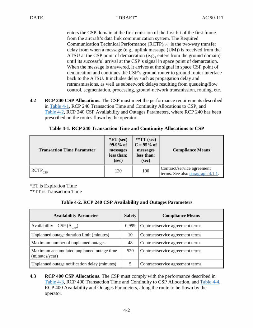
DATE “DRAFT” AC 90-117
enters the CSP domain at the first emission of the first bit of the first frame from the aircraft’s data link communication system. The Required Communication Technical Performance (RCTP)CSP is the two-way transfer delay from when a message (e.g., uplink message (UM)) is received from the ATSU at the CSP point of demarcation (e.g., enters from the ground domain) until its successful arrival at the CSP’s signal in space point of demarcation. When the message is answered, it arrives at the signal in space CSP point of demarcation and continues the CSP’s ground router to ground router interface back to the ATSU. It includes delay such as propagation delay and retransmissions, as well as subnetwork delays resulting from queueing/flow control, segmentation, processing, ground-network transmission, routing, etc.
4.2 RCP 240 CSP Allocations. The CSP must meet the performance requirements described in Table 4-1, RCP 240 Transaction Time and Continuity Allocations to CSP, and Table 4-2, RCP 240 CSP Availability and Outages Parameters, where RCP 240 has been prescribed on the routes flown by the operator.
Table 4-1. RCP 240 Transaction Time and Continuity Allocations to CSP
Transaction Time Parameter
*ET (sec)99.9% of messages less than:
(sec)
**TT (sec) C = 95% of messages less than:
(sec)
Compliance Means
RCTPCSP 120 100 Contract/service agreement terms. See also paragraph 4.1.1.
*ET is Expiration Time**TT is Transaction Time
Table 4-2. RCP 240 CSP Availability and Outages Parameters
Availability Parameter Safety Compliance Means
Availability – CSP (ACSP) 0.999 Contract/service agreement terms
Unplanned outage duration limit (minutes) 10 Contract/service agreement terms
Maximum number of unplanned outages 48 Contract/service agreement terms
Maximum accumulated unplanned outage time (minutes/year)
520 Contract/service agreement terms
Unplanned outage notification delay (minutes) 5 Contract/service agreement terms
4.3 RCP 400 CSP Allocations. The CSP must comply with the performance described in Table 4-3, RCP 400 Transaction Time and Continuity to CSP Allocation, and Table 4-4, RCP 400 Availability and Outages Parameters, along the route to be flown by the operator.
4-2

DATE “DRAFT” AC 90-117
Table 4-3. RCP 400 Transaction Time and Continuity to CSP Allocation
Transaction Time Parameter
*ET (sec)= 99.9% of messages less than:
(sec)
**TT (sec) C = 95%
of messages less than:
(sec)
Compliance Means
RCTPCSP 280 240 Contract/service agreement terms See also paragraph 4.1.1.
*ET is Expiration Time**TT is Transaction Time
Table 4-4. RCP 400 Availability and Outages Parameters
Availability Parameter Requirement Compliance Means
Availability – CSP (ACSP) 0.999 Contract/service agreement terms
Unplanned outage duration limit (minutes) 20 Contract/service agreement terms
Maximum number of unplanned outages 24 Contract/service agreement terms
Maximum accumulated unplanned outage time (minutes/year)
520 Contract/service agreement terms
Unplanned outage notification delay (minutes) 10 Contract/service agreement terms
4.4 RSP Specifications. The operator must ensure the CSP satisfies the allocated requirements for any RSP used by the operator. The Required Surveillance Technical Performance (RSTP)CSP is the one-way transfer delay from when a message is received at the CSP’s signal in space point of demarcation until its successful arrival at the other CSP’s ground router to ground router point of demarcation to the ATSU. It includes delay such as propagation delay and retransmissions, as well as subnetwork delays resulting from queueing/flow control, segmentation, processing, ground-network transmission, routing, etc. Delay is measured from the first bit emission of the first bit of the first frame/data packet from the aircraft’s Data Link Radio to the last bit exiting the CSP domain when it is received by the ground domain (ATSU).
4.4.1 RSP 180 CSP Allocations. The CSP must comply with the performance described in Table 4-5, RSP 180 Data Delivery Time and Continuity Criteria, and Table 4-6, RSP 180 Availability and Outages Parameters.
4-3

DATE “DRAFT” AC 90-117
Table 4-5. RSP 180 Data Delivery Time and Continuity Criteria
Data Delivery Time Parameter
*OT (sec)C = 99.9% of messages less than:
(sec)
**DT (sec) C = 95% of
messages less than:
(sec)
Compliance Means
RSTPCSP 170 84 Contract/service agreement terms. Pre-implementation demonstration.
*OT is data overdue time (associated with operational continuity)**DT is Delivery Time
Table 4-6. RSP 180 Availability and Outages Parameters
Availability Parameter Safety Compliance Means
Availability – CSP (ACSP) 0.999 Contract/service agreement terms
Unplanned outage duration limit (minutes) 10 Contract/service agreement terms
Maximum number of unplanned outages 48 Contract/service agreement terms
Maximum accumulated unplanned outage time (minutes/year)
520 Contract/service agreement terms
Unplanned outage notification delay (minutes) 5 Contract/service agreement terms
4.4.2 RSP 400 CSP Allocations. The CSP must comply with the performance described in Table 4-7, RSP 400 Data Delivery Time and Continuity Criteria, and Table 4-8, RSP 400 Availability and Outages Parameters.
Table 4-7. RSP 400 Data Delivery Time and Continuity Criteria
Data Delivery Time Parameter
OT (sec) C = 99.9% of messages less than:
(sec)
DT (sec) C = 95% of
messages less than:
(sec)
Compliance Means
RSTPCSP 340 270 Contract/service agreement terms. Pre-implementation demonstration.
*OT is data overdue time (associated with operational continuity)**DT is Delivery Time
4-4

DATE “DRAFT” AC 90-117
Table 4-8. RSP 400 Availability and Outages Parameters
Availability Parameter Safety Compliance Means
Availability – CSP (ACSP) 0.999 Contract/service agreement terms
Unplanned outage duration limit (minutes) 20 Contract/service agreement terms
Maximum number of unplanned outages 24 Contract/service agreement terms
Maximum accumulated unplanned outage time (minutes/year)
520 Contract/service agreement terms
Unplanned outage notification delay (minutes) 10 Contract/service agreement terms
4.5 CSP for U.S. Operations. The FAA provides Very High Frequency (VHF) Data Link (VDL) Mode 2 for all data link operations within the United States (except remote areas, which fall under paragraph 4.1). In addition, the FAA has authorized the use of VDL M0/A for CPDLC-DCL application. Operators can use the VDL Mode 2 subnetwork or may participate in CPDLC-DCL using VDL M0/A with no additional responsibilities. If the operator’s aircraft is equipped with a properly-functioning VDL M2 radio before starting the flight or dispatching, the FAA accepts the use of VDL M0/A en route when VDL M2 communications are lost.
4.5.1 Initial CSP Qualification. A CSP planning to offer an alternate subnetwork for data link communications in the United States should contact the FAA Data Communications Program Office. The CSP needs to provide substantiating information to demonstrate their subnetwork satisfies the requirements allocated to the CSP and will need to enter into an agreement with the FAA on the sharing of data, notification of outages, security of communication, and other detailed characteristics. For further information refer to the Data Communications Network Services (DCNS) Alternative Media Description.
4.5.2 Alternate Subnetworks. The FAA allows operators to select an alternate subnetwork provided the subnetwork satisfies the required performance allocation and the operator/CSP enters into an agreement to ensure the performance is achieved and maintained. The FAA identifies accepted alternate subnetworks by listing on the Performance-based Communication and Surveillance (PBCS) Monitoring website. CSPs will be notified of changes to this list.
4-5

DATE “DRAFT” AC 90-117
Table 4-9. Data Communications Network Services (DCNS) Performance Baseline
Performance Metric System Requirements Packet Error Rate (Network Service) 10(-5)
Availability - Reliability, Maintainability, Availability (RMA) (Network Service)
0.9999
Mean Time Between Outages (MTBO) – RMA (Network Service)
1,344 Hours
Network Service Restoral Time – RMA 30 Seconds*
En Route Capacity 0.0010 bps per km3
One-Way Latency at 95% (uplink or downlink) < 10 sec
One-Way Latency at 99% (uplink or downlink) < 45 sec
*RMA restoral time applies except for catastrophic processor failures and force major events,in which case the maximum restoration time must be within 3 minutes.
4.5.3 Operator Agreement with CSP. Operators using an alternate subnetwork qualified by the FAA have similar responsibilities as when using data link communications for oceanic and remote continental operations. The operator must ensure their CSP meet the following allocated requirements.
4.5.4 Transfer Delay.
1. The CSP uplink transfer delay must be less than or equal to 10 seconds for95 percent of all ATSU data messages.
2. The CSP downlink transfer delay must be less than or equal to 10 seconds for95 percent of all ATSU data messages.
3. The CSP uplink transfer delay must be less than or equal to 45 seconds for99 percent of all ATSU data messages.
4. The CSP downlink transfer delay must be less than or equal to 45 seconds for99 percent of all ATSU data messages.
4.5.4.1 Data Integrity. The Packet Error Rate at the CSP Network Service Delivery Point (SDP) must be less than 1x10⁻⁵. The packet error rate is the number of incorrectly received data packets divided by the number of received packets. A packet is declared incorrectly received if at least one bit is erroneous or if it is delivered to an incorrect recipient. This metric excludes packets lost in transmission due to connection failure or excessive latency, as those are accounted by other metrics.
4.5.4.2 Reliability, Maintainability, and Availability. The reliability, maintainability, and availability performance requirements presented in this section apply to the specific CSP subnetwork seeking qualification and should
4-6

DATE “DRAFT” AC 90-117
not take into account the availability of additional subnetworks in order to achieve the required performance levels. A network service thread includes all equipment between the CSP SDP and aircraft users, excluding any aircraft components. This would include the relevant emitting or receiving ground station antenna(s) as well as transmitting/receiving the necessary radio frequency (RF) signal levels across the entire ordered service volume in question. Signal levels need to account for terrain impacts, as applicable to the service volume in question. For the purposes of availability, utilization of diverse ground station sites and other means of redundancy are included to provide the required level of availability for the ordered service volume.
1. The service availability for each network service thread must beat least 0.9999.
2. The minimum calculated service availability must be measuredover the latest 12-month period. Availability is calculatedas follows:
• Available Time: Total time during the latest 12-month period theservice was under contract.
• Total Outage Time: The total unapproved service interruptionor degradation time during the Available Time. It includes anyunapproved degradation in which the service failed to meet allperformance requirements of this specification. It includes any lengthof time exceeding the duration of a FAA-approved interruptionor degradation.
4.6 CSP Monitoring. For and remote continental operations and for the use of alternate subnetworks for U.S. data communications, the operator must be aware of their CSP performance. The operator and CSP agreement should address performance monitoring and the performance data as necessary to remain in compliance.
4.6.1 U.S. Data Communications. If a CSP fails to satisfy the allocated requirements, the FAA will notify operators the allowance for alternate subnetwork has been suspended. In this case, the operator should not file or use the associated performance standard (if prescribed) until the FAA indicates the alternate subnetwork is compliant.
4-7

DATE “DRAFT” AC 90-117
CHAPTER 5. OPERATIONAL USE OF DATA LINK COMMUNICATIONS
5.1 Operational Use.
5.1.1 Minimum Equipment List (MEL) and Master Minimum Equipment List (MMEL). If an MEL is required, it must include any revisions necessary for data link communication operations. These provisions must be approved. Operators must adjust the MEL, or equivalent, and specify the required dispatch conditions. A sample MEL is provided in Appendix B, Data Link Communications Minimum Equipment List (MEL) and Master Minimum Equipment List (MMEL) Provisions.
5.1.2 Flight Plans. Dispatchers and pilots intending to conduct operations using data link communication must file an accurate flight plan (see Appendix D, Flight Planning). Air Traffic Service Unit (ATSU) automation relies on correct flight plan codes to determine aircraft and operator data communication eligibility for various services (e.g., reduced separation). If operators defer data link equipment before flight, a new flight plan should be filed reflecting the revised capability codes. The flight plan must always accurately reflect the aircraft’s current capabilities.
5.2 Data Link Operational Guidance. Pilots must be proficient with the equipment and procedures used for data link communication. Training must be based on operating guides from the manufacturer or approved operational procedures for operators with a FAA certificate. The Data Communications Implementation Team Tower Data Link Services Controller Pilot Data Link Communication Departure Clearance Service (CPDLC-DCL) Flight Deck User Guide is available to provide general data communication procedure guidance in the United States but is not a substitute for Original Equipment Manufacturer (OEM)/Airplane Flight Manual (AFM) procedures. For international operations, operators should reference International Civil Aviation Organization (ICAO): ICAO Doc 10037, Global Operational Data Link (GOLD) Manual, ICAO Doc 9869, Performance-Based Communication and Surveillance (PBCS) Manual, and state Aeronautical Information Publications (AIP).
5.2.1 Crew Resource Management (CRM). The pilot flying and pilot monitoring (not flying) should individually review each Controller-Pilot Data Link Communication (CPDLC) uplink message (UM) prior to responding to and/or executing any clearance and individually review each CPDLC downlink message (DM) prior to transmission. Reading a message individually is a key element to ensuring that each flightcrew member does not infer any preconceived intent different from what is intended or appropriate. Reading the message aloud would bias the other flightcrew member and could lead to the error of “reading” what was read aloud as opposed to what was actually displayed.
5.2.1.1 UMs. Some UMs, such as complex or conditional clearances, require special attention to prevent the flightcrew from responding to a clearance with ACCEPT/WILCO but not complying with that clearance. To minimize errors, when responding to a clearance with ACCEPT/WILCO, each flightcrew
5-1

DATE “DRAFT” AC 90-117
member should read the UM individually (silently) before initiating a discussion about whether and how to act on the message.
5.2.1.2 DMs. In a similar manner, each flightcrew member should individually review CPDLC DMs before the message is sent.
5.3 Logon.
5.3.1 Departing U.S. Domestic Airports. The logon should be 30 minutes prior to proposed departure time. Pilots should maintain KUSA until disconnected by air traffic control (ATC). If leaving U.S. domestic airspace, the automatic transfer from KUSA to the next data authority (NDA) may not be possible. In such cases, the pilot must manually log off KUSA and log on to the NDA.
Note: Intermittent NO COMM annunciations may occur and do not necessarily mean the ATC connection is lost. Pilots should delay before logging off to allow the annunciation to end as the system may reestablish the connection. Logging off and logging back on will cause the ATC connection to end and may block future connections.
5.3.2 Prior to Entering Oceanic and Remote Continental Airspace. The pilot should initiate a logon 10 to 25 minutes prior to entry into airspace where data link communication services are provided.
Note: Departing from a foreign airport close to or within oceanic and remote continental airspace may require the logon to be initiated prior to departure.
5.3.3 Required Data for Logon. To perform an initial logon request, the flightcrew enters the four character ICAO identifier of the ATSU and includes the following flight-specific information:
1. Aircraft identification (same as item 7 of the flight plan);
2. Aircraft registration and/or aircraft address (same as item 18 of theflight plan); and
3. Departure and destination airports, when required (same as items 13 and 16of the flight plan).
Note 1: When the aircraft identification includes a numeric component, this component must exactly match what is listed on the flight plan. In other words, “ABC3” does not match “ABC003.”
Note 2: While the ATSU identifier is only four characters, Aeronautical Telecommunications Network (ATN) Baseline 1 (B1) is capable of supporting up to eight characters.
Note 3: Ensure Automatic Dependent Surveillance-Contract (ADS-C) is “ON” or “ARMED” prior to logon.
5-2

DATE “DRAFT” AC 90-117
5.3.4 Data Must Match Flight Plan. To avoid an automatic rejection of the logon request, the flightcrew must ensure the flight-specific information entered into the aircraft system is the same as the corresponding details filed in the flight plan.
5.3.5 Possible Reasons for Failed Logon. The following are possible reasons for receiving an indication of logon failure:
1. Logon information does not exactly match flight plan (e.g., incorrect tailnumber and/or call sign/flight ID);
2. Ground or air system anomaly;
3. Data corruption;
4. Suspected duplicate aircraft registration;
5. Aircraft intentionally blocked from logging on (i.e., on blocked list due toproblem reports with the aircraft);
6. There is no flight plan for the flight or the flight plan did not transfer fromone ATSU to the next;
7. The aircraft registration/address in the logon request message does not matchthe aircraft registration/address in the flight plan; and/or
8. The automatic current data authority (CDA) to NDA transfer failed or unable.
5.3.6 Failure of Data Link Communication Connection. When failure of a data link communication connection is detected, the flightcrew should terminate the connection and then initiate a new logon with the current ATSU. If another failure occurs, revert to voice communication.
5.3.7 Logon Response. The logon response message provides information to the aircraft system concerning whether:
1. The logon request was successful (e.g., could be correlated with aflight plan); or
2. The logon request was unsuccessful (e.g., could not be correlated with aflight plan).
5.4 En Route. Normally, response to CPDLC messages should be via CPDLC and response to a voice message should be via voice. However, if a CPDLC message is unclear or conflicting, always clarify with voice.
5.4.1 Contact or Monitor Message. A CONTACT or MONITOR message instructs the flightcrew to change to the specified frequency and may include a position or time for when to change to the new frequency. Use of a contact or monitor message is as follows:
1. When a MONITOR message is received, the flightcrew should change to thespecified frequency upon receipt of the instruction or at the specified time
5-3

DATE “DRAFT” AC 90-117
or position. The flightcrew should not establish voice contact on the frequency.
2. When a CONTACT message is received, the flightcrew should change to thespecified frequency upon receipt of the instruction or at the specified timeor position, and establish voice contact on the frequency.
5.4.2 Waypoint Sequencing. The flightcrew should ensure waypoints are sequenced correctly. If an aircraft passes abeam a waypoint by a distance greater than the aircraft flight management system (FMS) waypoint automatic sequencing parameter, the flightcrew should manually sequence the waypoints in the FMS.
5.4.3 Multi-Part Messages. If pilots are unable to comply with any portion of a multi-part message, reject (“REJ”) or “UNABLE” the entire message. Additionally, pilots should avoid sending multiple requests to the ATSU in a single message.
5.4.4 CPDLC Connection Failure. If a CPDLC dialogue is interrupted by a data link service failure, expect the controller to recommence the entire dialogue by voice communication. When the controller recognizes a failure of the CPDLC connection, the controller will instruct the flightcrew to terminate the connection and then initiate another logon. See Table 5-1, CPDLC Connection Failure Responses, for the voice phraseology in response to a connection failure.
Table 5-1. CPDLC Connection Failure Responses
Controller/Pilot Response Controller (or radio operator) CPDLC FAILURE.
DISCONNECT CPDLC THEN LOGON TO [facility designation]
Pilot DISCONNECTING CPDLC WITH [facility designation]. LOGGING ON TO [facility designation]
Note: Additional voice phraseology is available in Appendix E, Voice Phraseology.
5.5 Voice Monitoring. Pilots must continuously monitor very high frequency (VHF) or high frequency (HF) as appropriate and/or maintain a Selective-Calling Radio System (SELCAL) watch.
5.5.1 Pilot Response. As with voice communication, pilots should respond as soon as possible to all data link communication messages (e.g., Accept/Wilco, Reject/Unable, or Standby). If more time is needed to make a decision and respond, select standby (“STBY”).
5.6 Free Text Messages. Free text messages should only be used when a standard message element does not exist or is inadequate. When sending a free text message, use standard ATSU phraseology and avoid using non-standard abbreviations. (See Appendix E.)
5-4

DATE “DRAFT” AC 90-117
Note 1: For Future Air Navigation Systems (FANS) 1/A implementations, the flightcrew cannot respond to the free text message element with WILCO, UNABLE, or STANDBY.
Note 2: When the controller uses free text to ask the crew affirmative/negative questions, the pilot can only respond with ROGER, which means they have read and understood the message, but does not answer the question affirmatively. In these cases, the flightcrew should respond to the question with a separate message (see Appendix E).
5.7 Data Link Communication Failures. The flightcrew must notify the ATSU as soon as practical of any indications of degraded performance resulting from a failure or loss of connectivity in accordance with 14 CFR part 91, § 91.187. For example, reportable events include:
1. When operating outside of VHF coverage area and the SatelliteCommunication (SATCOM) data link communication system fails; and
2. When operating in airspace where ATSU surveillance services are providedand the VHF data link communication system fails.
Note: Timely notification is appropriate to ensure the ATSU has time to assess the situation and apply a revised separation standard, if necessary.
5.7.1 Failure of Automatic Transfer. If an automatic transfer of the CPDLC connection does not occur at the boundary (CDA to NDA), the flightcrew should contact the transferring ATSU by sending a CPDLC TRANSFER FAILURE message or voice equivalent, advising them the transfer has not occurred.
5.7.2 Actions and Phraseology for Data Link Communication Failure. In the event of an aircraft data link communication system failure, the flightcrew should revert to voice and notify the ATSU of the situation. For example, for a CPDLC failure, the flightcrew should use the voice phraseology, “CPDLC failure, continuing on voice,” as shown in Table E-1, Voice Phraseology Related to CPDLC from Flightcrew. The flightcrew continues to use voice until the functionality of the aircraft system can be reestablished.
5.8 ADS-C. Normally, the flightcrew should leave ADS-C armed for the entire flight. However, in airspace where ADS-C is available, if the flightcrew switches ADS-C off for any reason, or they receive indication of avionics failure leading to loss of ADS-C, the flightcrew should advise ATC and follow alternative procedures.
5.8.1 Airspace Where ADS-C Is Not Available. In airspace where ADS-C is not available, the flightcrew may switch ADS-C off to cancel inadvertent ADS-C connections. In such cases, the flightcrew should ensure the ADS-C is armed when reentering airspace where ADS-C is again available.
5.8.2 Emergencies. The pilot may activate the ADS-C emergency mode, which changes all existing ADS-C periodic contracts from normal mode to emergency mode and creates
5-5
DATE “DRAFT” AC 90-117
emergency mode ADS-C periodic contracts on any ADS-C connections that do not have a periodic contract already in place. The flightcrew may also activate ADS-C emergency mode by sending a “MAYDAY” CPDLC message. ADS-C emergency mode may be deactivated by the ATSU or by the flightcrew sending a “CANCEL EMERGENCY” CPDLC message. In emergencies, pilots should revert to voice communication when able.
5.9 Exiting CPDLC and ADS-C Areas. The ATSU should automatically disconnect data authority approximately 15 minutes after exiting CPDLC and/or ADS-C areas. After 15 minutes, if aircraft equipment permits, the flightcrew should ensure there are no active CPDLC or ADS-C connections. Ensuring connections are not active eliminates the possibility of inadvertent or inappropriate use of the connections.
5.9.1 Contact Current ATSU. The flightcrew should contact the current ATSU unit prior to the manual termination of any ADS-C connection, even if it is suspected to be unnecessary or its termination has failed.
5.9.2 Connection Termination Failed. In the event the connection termination has failed, the flightcrew should contact the ATSU via voice or any other appropriate means.
5.10 Logoff. Prior to logoff, the pilot should ensure there are no unresolved or open messages. Log off and confirm CPDLC connection is terminated and continue with voice communication.
Note: Flightcrews should wait at least 10 minutes after landing before initiating a CPDLC-Departure Clearance (DCL) logon to ensure En Route Automation Modernization (ERAM) and Tower Data Link Services (TDLS) have enough time to clear previous flight information.
5.10.1 NAS Logoff. Logoff should automatically occur approximately 5 minutes after departure. Do not log off until ATC terminates the session. If proceeding to international or oceanic and remote continental airspace and CPDLC services are not terminated, then manually log off prior to a new logon.
5.10.2 International and Oceanic and Remote Continental Logoff. The ATSU should automatically disconnect data authority approximately 15 minutes after exiting CPDLC and/or ADS-C areas.
Note: For transitions between data link communication systems (i.e., FANS to ATN), follow OEM procedures for logon/logoff requirements specific to your avionics system.
5-6

DATE “DRAFT” AC 90-117
CHAPTER 6. PERFORMANCE MONITORING
6.1 Performance Monitoring. With the implementation of performance based systems, monitoring of those systems ensures compliance. Monitoring provides a higher level of confidence the operational system will continue to meet the Required Communication Performance (RCP)/Required Surveillance Performance (RSP) specification. Operators must participate in performance monitoring which includes reporting and addressing problems. The goal of monitoring data link communication performance is to:
• Maintain safe and efficient operations;
• Determine continued compliance and interoperability;
• Investigate problems; and
• Share lessons learned.
6.2 Oceanic and Remote Continental Airspace.
6.2.1 FAA Data Collection. The FAA, along with other Air Traffic Service Units (ATSU), has been monitoring Controller-Pilot Data Link Communication (CPDLC) and Automatic Dependent Surveillance-Contract (ADS-C) transactions since 2009. Analysis of Actual Communications Performance (ACP) for the CPDLC transactions and Actual Surveillance Performance (ASP) for the ADS-C downlink messages (DM) are accomplished on a semi-annual basis with an emphasis on the nominal continuity (95 percent) requirements associated with safety.
6.2.2 RCP Performance Analysis. Data analysis of ACP, including the Actual Communication Technical Performance (ACTP), is compared against RCP standards (see tables in paragraph 2.15) to determine whether the CPDLC performance is adequate.
6.2.3 RSP Performance Analysis. ASP is compared against RSP standards (see tables in paragraphs 2.16.6 and 2.16.8) to determine whether surveillance performance is adequate. Actual Surveillance Technical Performance (ASTP) analysis is based on the calculation of delivery time of the ADS-C periodic and event reports between the aircraft and the ATSU ground system.
6.2.4 Evaluating Operational and Nominal Transaction Times. ACP and ASP are evaluated using operational (99.9 percent) and nominal (95 percent) continuity criteria. Observed ACP and ASP must meet or exceed the nominal 95 percent continuity requirements.
Note 1: If ACP/ASP does not meet the nominal continuity, the operator will be notified and should not continue data link operations at the associated performance level until the issue is resolved (see paragraphs 6.4 and 6.5).
Note 2: If ACP does not meet the operational continuity 99.9 percent, the operator is notified to investigate and initiate corrective action. The nominal performance 95 percent is still sufficient for data link communication performance.
6-1

DATE “DRAFT” AC 90-117
6.3 Performance Website. Operators may obtain a Pass/Fail/insufficient data monitoring performance report for their aircraft from the FAA Performance-based Communication and Surveillance (PBCS) Monitoring website.
6.4 Substandard Performance. Operators must address substandard performance whether the source of that report is from the operator’s own monitoring process, Communication Service Provider (CSP), FAA, or a foreign authority. Operators can view aggregate performance observed within FAA oceanic airspace from the PBCS monitoring website in the above paragraph. If the result of the report is “Fail,” the operator should follow the directions on the website to request further details and a corrective action plan. With a “Fail” report, operators may continue to operate at a less stringent performance level (i.e., RCP 240 to RCP 400) provided they file the appropriate performance flight plan designator.
6.5 Corrective Aircraft Action. The operator may return to the performance stated in their statement of compliance (SOC) provided the corrective action plan is completed in accordance with Original Equipment Manufacturer (OEM) procedures.
6.6 Data Link Performance Eligibility. As stated in paragraph 3.3.4, RCP and RSP performance data should be included to quantify data link eligibility. If performance data is insufficient, then the SOC will be the initial basis for compliance with continued monitoring.
6.7 Procedures to Report Problems. The operator should establish procedures to report problems to the regional PBCS monitoring entities identified in Aeronautical Information Publications (AIP) (or equivalent publications) associated with the route of flight on which the problem occurred (see Chapter 8).
6.8 Performance Monitoring in the National Airspace System (NAS). Reserved.
6-2

DATE “DRAFT” AC 90-117
CHAPTER 7. TRAINING
7.1 Training Documentation.
7.1.1 Part 91 Operator Training. Part 91 operators must be proficient with the procedures and operations associated with the use of data link communication systems in accordance with their Airplane Flight Manual (AFM) and AFM Supplement if applicable.
7.1.2 Parts 91 Subpart K (Part 91K), 121, 125, and 135 Operator Training. Part 91K, 121, 125, and 135 operators should have a training program addressing the operational practices, procedures, and training items related to data link communication operations (e.g., initial, upgrade, or recurrent training for pilots, operational control personnel, and maintenance personnel).
Note: A separate training program is not required if data link communication training is integrated in the current training program. However, the applicant must identify the training elements from this AC within the existing training program.
7.2 Objectives. Operators should include the following objectives to ensure appropriate flightcrew data link communications qualification:
• Provide necessary pilot knowledge of data link performance-based communicationand surveillance concepts, systems, procedures, and skills to properly respond todata link communication clearances and advisories; and
• Identify human factor issues specific to pilot operation and interaction with thecommunication software, hardware, and operating environment (e.g., head-downtime, situational awareness, or loss of pilot response time in the RequiredCommunication Performance (RCP) specification).
7.3 Ground and Flight Training.
7.3.1 Pilot Knowledge/Training. Parts 91K, 121, 125, and 135 operators should maintain training syllabi (e.g., initial, upgrade, or recurrent) and other appropriate materials including operational practices and procedures. Training for other personnel must be included where appropriate (e.g., operational control personnel or maintenance).
7.3.2 Pilot Training. Parts 91K, 121, 125, and 135 operators should ensure their process contains training for pilots on equipment requirements, normal and non-normal operations and procedures, and limits of their data link communication capability. Pilots must receive data communications training specific to the avionics suite they will be operating. A common type rating does not guarantee the pilot has received training on the data communications equipment installed on a particular aircraft.
7-1

DATE “DRAFT” AC 90-117
7.3.3 Regulatory Basis. All training must be in accordance with the following where applicable:
1. Part 91:
• § 91.1073, Training Program: General.
• § 91.1081, Crewmember Training Requirements.
• § 91.1111, Maintenance Training.2. Part 121:
• § 121.375, Maintenance and Preventive Maintenance Training Program.
• § 121.401, Training Program: General.3. Part 135:
• § 135.323, Training Program: General.
• § 135.329, Crewmember Training Requirements.
• § 135.433, Maintenance and Preventive Maintenance Training Program.
7.4 Pilot Knowledge Subject Areas. The minimum following subjects should be addressed in an approved curriculum of data link communications academic training during the initial introduction of a crewmember to data link communication systems:
1. Normal pilot response to data link communication messages to include:acknowledgment, acceptance/WILCO, rejection/unable, standby,or cancellation (i.e., closure) of a data link communication message;
2. Message elements in the message set used in each environment (e.g., ground,oceanic, en route) including terms, abbreviations, and conventions;
3. RCP/Required Surveillance Performance (RSP) specifications and theirperformance requirements;
4. Depiction on charts or in manuals, and terminology associated withapplications (e.g., Controller-Pilot Data Link Communication (CPDLC) andAutomatic Dependent Surveillance-Contract (ADS-C) reporting contracts);
5. Implementation of reduced separation with associated data communicationsystem requirements to comply with RCP 240 and RSP 180 or other possibleperformance requirements associated with their routes;
6. Data link communications system theory (relevant to operational use);
7. Operations involving data link communication services;
8. Nominal and unacceptable performance;
9. Normal and non-normal use;
10. Data link communication events and reporting (see Chapter 8);
11. AFM and AFM Supplement limitations;
7-2

DATE “DRAFT” AC 90-117
12. Crew Resource Management (CRM) of independent message verification,discussion, and action (see paragraph 5.2.1);
13. Minimum equipment list (MEL), deferrable items, and procedures; and
14. Human factors specific to the operating environment and operation ofinstalled communication equipment.
Note: For subsequent ground training, only the new, revised, or emphasized items need be addressed.
7.5 Pilot Procedural Training Items. As a minimum, procedural training should include:
1. Proper use of data link communication controls, procedures, and limitations.
2. Logon procedures and reestablishing system operation after loss of networklogon.
3. Display features.
4. Weather deviations, offsets, and waypoint sequencing.
5. Advisories and annunciation.
6. Timely and correct responses to data link communication failures.
7. Recognition of data link communications system failures and data linkcommunication issues unique to the air carrier or operator.
8. Appropriate interaction with the Air Traffic Service Unit (ATSU) followingdata link communication messages that are not acceptable.
9. CRM. Independent message verification, discussion, and action(see paragraph 5.2.1).
10. Accepting, rejecting, or canceling messages.
11. Storing and retrieving messages.
12. Loading messages into appropriate controls/displays for use (e.g., flightmanagement system (FMS)) formulating and sending messages.
13. Departures and departure transitions are not included in the loadable routeuplink and must be manually entered by the crew into the FMS when providedin the Departure Clearance (DCL). Refer to the Data CommunicationsImplementation Team Tower Data Link Services Controller Pilot Data LinkCommunication Departure Clearance Service (CPDLC-DCL) Flight DeckUser Guide.
14. Loading message requests from the FMS (e.g., flight plan waypoints intodata link communication for transmission, if applicable).
15. Managing the communications systems.
16. Establishing and terminating system operation.
7-3
DATE “DRAFT” AC 90-117
17. Switching use of Radio Frequency (RF) media (if this is a crew-controllablefeature).
18. Items particular to an air carrier’s implementation or the uniqueness of itsaircraft capability and/or procedures.
19. Applicable message sets, expected transmission times, failure annunciations,constraints, and limitations.
20. CRM in responding to data link communication exchanges.
21. Data link communication modes of operation.
22. Normal and non-normal pilot operating procedures.
7.5.1 Credit for Training. Operators may receive credit for existing data link communications training already approved in a different application. For example, an operator may receive credit for training based on previous use of data link communication services, such as on different routes, for a different type of operation, or (except for part 121 or 135) training conducted by another operator, training center, or manufacturer. The principal operations inspector (POI) will determine whether and how much credit an operator should receive, considering whether the training is used in another FAA-approved application and whether the operator has demonstrated the training is relevant to the new application.
7.5.2 Pilot Currency. Once pilots have completed initial data link communication training, pilot currency programs/training should include data link communication elements.
7.6 Dispatcher Training. An aircraft dispatcher, flight follower, or other operational control personnel should not be assigned to duty unless he/she has demonstrated satisfactory data link communication knowledge to the operator. Training should include:
• Proper use of flight plan designators (see Appendix D, Flight Planning);
• ATSU separation criteria and procedures;
• MEL remarks or exceptions based on data link communications;
• Procedures for transitioning to voice communication and other contingencyprocedures related to the operation in the event of abnormal behavior of the data linkcommunication services;
• Coordination with the ATSU related to or following a special data linkcommunication exceptional event; and
• Contingency procedures to transition to a different separation standard when data linkcommunication services fail.
7.7 Maintenance Training. Operators should ensure all maintenance personnel receive training on their airplane’s data link communication equipment. Operators unsure of required maintenance procedures for data link communication-related equipment should contact their aircraft manufacturer field service representatives.
7-4

DATE “DRAFT” AC 90-117
CHAPTER 8. REPORTS
8.1 Introduction. Operators and manufacturers must develop reporting procedures to ensure effective identification, tracking, and followup of data link-related events. Such procedures should focus on providing useful information to:
• Properly assess the importance of data link communication events;
• Follow-up on information related to specific data link communication eventsas necessary; and
• Keep the industry and FAA informed on data link communication performance in theNational Airspace System (NAS) and international operations.
8.2 Oceanic and Remote Continental Problem Reporting. Problem reporting in oceanic and remote continental airspace involves notifying the Regional Monitoring Agency for the region where the problem occurred (e.g., Data Link Monitoring Agency (DLMA) for North Atlantic (NAT) operations). NAT DLMA is co-managed with the Informal South Pacific ATC Coordinating Group (ISPACG) and ISPACG Central Reporting Agency (CRA). For FANS 1/A problem reporting, visit the Future Air Navigation Systems (FANS) 1/A Problem Reporting website. Common reasons for submitting a problem report are:
1. Failure to log on,
2. Disconnect,
3. Corrupted messages, and
4. Excessive delay.
8.3 NAS Problem Reporting. For data link communication problems in the NAS, an Operational Problem Report (OPR) should be filed with Harris Corporation by downloading the following Data Comm Operational Problem Report Ticket.
8-1

DATE “DRAFT” AC 90-117 Appendix A
APPENDIX A. FOREIGN OPERATORS
A.1 General. Foreign operators may use data link communications when operating in U.S. airspace. Foreign operators are not required to install and use data link communications for any aircraft or operations unless required for Air Traffic Service Unit (ATSU) separation standards based on appropriate flight plan equipment code(s) (see Appendix D, Flight Planning).
A.2 Title 14 CFR Part 129. The FAA does not approve data link communications installations, training programs, minimum equipment lists (MEL), or maintenance programs for foreign operators operating non-U.S. registered aircraft. Such authorizations are addressed as specified by the State of the Operator. However, since compatibility of data link communications within U.S. airspace is essential, part 129 operations guidelines for data link communications are provided by this AC. Compliance with these data link communications provisions ensures both data link communication system and procedural compatibility. An operations specification (OpSpec) or an amendment to existing OpSpecs for data link communications must be issued prior to operating data link communication-equipped aircraft in domestic U.S. airspace or with U.S. domestic facilities.
A.3 Application Process. Foreign operators should contact their FAA principal operations inspector (POI) to obtain application information for part 129 data link communications OpSpecs in U.S. airspace. When a foreign operator submits the necessary information to the respective principal inspector (PI), showing its aircraft are in compliance, the PI approves those OpSpecs or an amendment. Although not mandatory, foreign operators should comply with the provisions of this AC or equivalent provisions specified by the State of the Operator or by International Civil Aviation Organization (ICAO).
A.4 Unique Address. An appropriate data link communication system must be installed and operated on suitable frequencies specified by the ATSU during flight in U.S. airspace if procedures are predicated on its use. A unique and specific address, the ICAO 24-bit aircraft identification, must be assigned to the airplane and the data link communication must recognize this address. When properly set, the unique address may not be altered, set to a duplicated address, or set to an address that potentially interferes with the ATSU or data link communication safety functions.
A.5 Performance Standard for Two-Way Data Link Communications. A data link communication capable of coordinating with air traffic facilities using RTCA DO-258A/ED-100A, Minimum Operational Performance Standard (MOPS) for the ATSU Two-Way Data Link Communications, or other equivalent standards must be installed if operations will be predicated on its use. The data link communication system should be operated in an appropriate data link communication mode during flight in U.S. airspace using data link communication, except as provided for by the MEL provisions acceptable to the State of the Operator.
A-1

DATE “DRAFT” AC 90-117 Appendix A
A.6 Training. Training and procedures for use of data link communication as specified by ICAO, this AC, or other equivalent criteria acceptable to the FAA should be used when operating in U.S. airspace.
A.7 Unsafe Performance or Conditions. Unsafe performance or conditions related to data link communication operations which potentially could affect continued safe operations in U.S. airspace (a data link communication event) should be reported to their International Field Office (IFO) (refer to the FAA’s IFO website). Operators should also follow the problem reporting procedures in Chapter 8 of this AC.
A-2

DATE “DRAFT” AC 90-117 Appendix B
APPENDIX B. DATA LINK COMMUNICATIONS MINIMUM EQUIPMENT LIST (MEL) AND MASTER MINIMUM EQUIPMENT LIST (MMEL) PROVISIONS
B.1 Inoperative Equipment. Each operator intending to have authority to dispatch an aircraft with a data link communication system or component temporarily inoperative must do so in accordance with provisions of a minimum equipment list (MEL). MELs are approved for each operator and type aircraft, within provisions of the FAA Master Minimum Equipment List (MMEL) for that type. The operator’s MEL must not be less restrictive than the MMEL, Title 14 CFR, the operations specifications (OpSpec)/management specifications (MSpec), the Airplane Flight Manual (AFM) limitations, certification maintenance procedures, or Airworthiness Directives (AD). When proposed MEL provisions are consistent with the FAA MMEL, principal operations inspectors (POI) may approve the MEL. If less restrictive MEL or different MEL provisions are requested, a proposal for consideration of an FAA MMEL change must be forwarded to the Aircraft Evaluation Group (AEG) assigned for that aircraft type. Enhanced features (those above and beyond the basic data link communication system) may be inoperative, provided the inoperative features do not degrade the system (e.g., data link communication printers).
Note: Title 14 CFR part 91, § 91.213 does not provide MMEL relief should equipment fail that is not included in the MMEL/MEL.
Table B-1. Minimum Equipment List Example
B-1

DATE “DRAFT” AC 90-117 Appendix B
Table B-2. Example of a Data Link Communication MMEL Provision
Note 1: The provisions and repair category intervals are intended to grant the operator sufficient relief during the initial stages of the data link communication implementation. This is intended to promote the installation process, as well as support the use of a partial system. Both equipment reliability and operational experience will dictate, what, if any, revision to this MMEL relief should be considered after the installation phase is completed.
Note 2: Operators are responsible for entering the number in the “Number Installed” column of the MEL.
Note 3: Operators are responsible for entering alternate procedures in the MEL comment section or referencing the location of such procedures in their manual system.
Note 4: If MMEL has not been updated for Controller-Pilot Data Link Communication (CPDLC) equipment for aircraft that are issued a Supplemental Type Certificate (STC), the operator is reminded that they must adhere to § 91.213.
Note 5: Special Condition: The MMEL does not provide relief for inoperative data communications equipment at this time and is being reviewed at the Aircraft Evaluation Group (AEG). Should any of the equipment/software fail relative to data link communications, the data equipment/software must be replaced/repaired before the aircraft can take off according to § 91.213(a). When the MMEL is amended by AEG for data link communication equipment, the Special Conditions paragraph must be removed from this OpSpec.
B-2

DATE “DRAFT” AC 90-117 Appendix C
APPENDIX C. SUMMARY OF AIRSPACE REQUIREMENTS
C.1 Summary of Airspace Requirements. (Table C-1, Summary Airspace Requirements.) Each Air Traffic Service Unit (ATSU) providing data link services defines the requirements for their operations (refer to International Civil Aviation Organization (ICAO) Doc 4444, ICAO Doc 7030, ICAO Doc 10037, Aeronautical Information Publications (AIP), and flight information region (FIR) specific bulletins for additional information).
Table C-1. Summary Airspace Requirements
Airspace Service
(Operational Use)
Aircraft Data Link Communication
System (Interoperability)
ATSU Provided
Subnetwork
Operator-Provided
Subnetwork
Performance Specification
U.S. (Domestic)
CPDLC-DCL service
FANS 1/A(+) VDL M2 or VDL M0/A
N/A N/A
U.S. (Domestic)
En route data communication services
FANS 1/A(+) VDL M2 VDL M0/A* TBD
Continental (Domestic)
European data link program
ATN B1 VDL M2 N/A N/A
Oceanic and Oceanic and FANS 1/A(+) N/A SATCOM) RCP 240 remote remote (Classic Aero, continental continental
23 NM lateral or along-track spacing***
SBB, or SBD)**
Oceanic and 50 NM FANS 1/A(+) N/A SATCOM RSP 180 remote Longitudinal (Classic Aero, continental SBB, or
SBD)**
Oceanic and remote continental
30 NM FANS 1/A(+) N/A SATCOM RCP 240 Longitudinal (Classic Aero,
SBB, or SBD)**
Oceanic and 5 Minute FANS 1/A(+) N/A SATCOM RSP 180 Remote Longitudinal (Classic Aero,
SBB, or SBD)**
Oceanic and N/A FANS 1/A ADS-C N/A SATCOM N/A remote (Classic Aero, continental SBB, or
SBD)**
C-1

DATE “DRAFT” AC 90-117 Appendix C
Airspace Service
(Operational Use)
Aircraft Data Link Communication
System (Interoperability)
ATSU Provided
Subnetwork
Operator-Provided
Subnetwork
Performance Specification
Oceanic and remote continental/ Domestic
N/A ACARS VDL M2 or VDL M0/A
SATCOM (Classic Aero, SBB, or SBD)**
N/A
Note: Table C-1 asterisks:
* An approval is required to use VDL M0/A for U.S. en route datacommunications and the operator assumes responsibility for the Communication Service Provider (CSP). The allocation of performance requirements to the CSP is more stringent than the RCP 240 allocation, which is used only to identify the aircraft allocation. See Chapter 4 of this AC.
** Aircraft typically use VDL M0/A or VDL M2 when in range of ground radios, which is also acceptable. However, an aircraft with only these subnetworks would not be eligible for the oceanic and remote continental operations due to coverage limitations.
*** See ICAO Doc 4444 for more information.
Table C-2. Subnetwork Designators
Subnetwork Designator Description of Designator
VDL M0/A Very high frequency data link – Mode 0/A
VDL M2 Very high frequency data link – Mode 2
HFDL High frequency data link
SATCOM (Classic Aero) INMARSAT or MT-SAT – Classic Aero satellite communications
SATCOM (SBB) INMARTSAT – Swift Broadband satellite communications
SATCOM (SBD) Iridium – short burst data satellite communications
C-2

DATE “DRAFT” AC 90-117 Appendix C
Table C-3. Preferred Original Equipment Manufacturer Annotation
“The FAA has approved the aircraft data link system to the criteria in AC 20-140C for the following data link capabilities:
Interop Designators: FANS 1/A+ (with automation) ATN B1 B2 ACARS ATS
Subnetworks: VDL M0/A/2 SATCOM (Classic Aero, SBD, SBB) HFDL ACARS ATS
Aircraft-Allocated Performance CPDLC: RCP 130, RCP 240, RCP 400 ADS-C: RSP 160, RSP 180, RSP 400
This design approval does not constitute operational authorization.”
C-3

DATE “DRAFT” AC 90-117 Appendix D
APPENDIX D. FLIGHT PLANNING
D.1 Filing Required Communication Performance (RCP)/Required Surveillance Performance (RSP) Capabilities. When filing RCP/RSP capabilities, operators should ensure the planned use of associated communication and surveillance capabilities for the flight will be in accordance with regulations, policies, and procedures in control areas for the flight, as published by the applicable States in Aeronautical Information Publications (AIP) (or equivalent publications). Operators should ensure the proper information to denote Performance-based Communication and Surveillance (PBCS) capabilities is included in the International Civil Aviation Organization (ICAO) flight plan.
D.1.1 The following are considerations for proper filing:
1. Presence of relevant serviceable equipment on board the aircraft.
2. Equipment and capabilities commensurate with flightcrew qualifications.
3. When applicable, appropriate authorizations as described in FAA operationsspecifications (OpSpec)/management specifications (MSpec)/letters ofauthorization (LOA).
D.2 Regulatory Basis. Flight planning must be in accordance with the following where applicable:
1. Part 91:
• § 91.169, IFR Flight Plan: Information Required.
• § 91.173, ATC Clearance and Flight Plan Required.2. Part 121:
• § 121.667, Flight Plan: VFR and IFR: Supplemental Operations.
• § 121.695, Disposition of Load Manifest, Dispatch Release, and Flight Plans:Domestic and Flag Operations.
• § 121.697, Disposition of Load Manifest, Flight Release, and Flight Plans: Supplemental Operations.
3. Part 125, § 125.405, Disposition of Load Manifest, Flight Release, andFlight Plans.
D.2.1 Flight Plan Descriptors:
• D1and G1 for Automatic Dependent Surveillance-Contract (ADS-C) (Table D-2,Item 10b Flight Plan Descriptors for Surveillance Equipment);
• J1 through J7 for Controller-Pilot Data Link Communication (CPDLC) (Table D-1,Item 10a Flight Plan COM Descriptors);
• M1 through M3 for Satellite Voice (SATVOICE) (Table D-1); and
• P1 through P3 for RCP Performance (Table D-1).
D-1

DATE “DRAFT” AC 90-117 Appendix D
Note 1: M1 through M3 and D1 in item 10 denote the interoperability for the aircraft equipment.
Note 2: Refer to ICAO Doc 4444, Procedures for Air Navigation Services – Air Traffic Management, Appendix 2, for flight plan requirements. Also, refer to the FAA Flight Planning Information website.
Note 3: The inclusion of PBCS capability in the filed flight plan indicates that the relevant aircraft equipment comprising the aircraft system is approved and serviceable, and the operator is eligible (e.g., flightcrew training and qualification) to use the equipment for PBCS operations. If these conditions are not met then PBCS capability should not be included in the flight plan.
D.3 Example. As a flight plan example, use the following:
If Actual Communications Performance (ACP) meets at least RCP 240 at 95 percent and Actual Surveillance Performance (ASP) meets at least RSP 180 at 95 percent, then the operator approved for RCP 240/RSP 180 may file the following:
• Field 10: “P2.”
• Field 18: “SUR/RSP180.”
D.3.1 If ACP does not meet RCP 240 at 95 percent, then the operator may file for RCP 400 by entering P1 and/or P3 in field 10. If ASP does not meet RSP 180 at 95 percent, then the operator may file for RSP 400 by entering “SUR/RSP400” in field 18.
D.4 Item 10a Descriptors. In Item 10a of the flight plan, operators should insert one of the descriptors, P1-P2, as appropriate, listed in Table D-1, to identify an aircraft’s RCP capability:
D-2

DATE “DRAFT” AC 90-117 Appendix D
Table D-1. Item 10a Flight Plan COM Descriptors
Descriptors System J1 CPDLC ATN VDL Mode 2
J2 CPDLC FANS 1/A HFDL
J3 CPDLC FANS 1/A VDL Mode 0/A
J4 CPDLC FANS 1/A VDL Mode 2
J5 CPDLC FANS 1/A SATCOM (INMARSAT)
J6 CPDLC FANS 1/A SATCOM (MTSAT)
J7 CPDLC FANS 1/A SATCOM (Iridium)
M1 ATC RTF SATCOM (INMARSAT)
M2 ATC RTF (MTSAT)
M3 ATC RTF (Iridium)
P1 CPDLC RCP 400
P2 CPDLC RCP 240
D.5 Item 10b Descriptors. In Item 10b of the flight plan, operators should insert one of the descriptors, D1 and G1, as appropriate, listed in Table D-2, to identify an aircraft’s RSP capability:
D-3

DATE “DRAFT” AC 90-117 Appendix D
Table D-2. Item 10b Flight Plan Descriptors for Surveillance Equipment
INSERT N if the aircraft does not have operable surveillance equipment for the route to be flown, OR INSERT one or more of the following descriptors, to a maximum of 20 characters, to describe the serviceable surveillance equipment and/or capabilities on board:
Descriptor System
D1 ADS-C with FANS 1/A capabilities
G1 ADS-C with ATN capabilities
D.6 Item 18 RSP Specification. In Item 18 of the flight plan, the aircraft operator should file the RSP capability by inserting the indicator SUR/ followed by the appropriate RSP specification (e.g., RSP 400 or RSP 180).
Note: The ATSU unit uses the flight plan information to determine when to apply particular Air Traffic System Management (ATM) operations that are dependent on the capability and to configure the system (e.g., set timer threshold values) for efficient operation when RCP and/or RSP varies.
D-4

DATE “DRAFT” AC 90-117 Appendix E
APPENDIX E. VOICE PHRASEOLOGY
Table E-1. Voice Phraseology Related to Controller-Pilot Data Link Communication (CPDLC) from Flightcrew
Condition Voice Phraseology To notify air traffic control (ATC) of a correction to a CPDLC message. (International Civil Aviation Organization. (ICAO) Doc 4444)
DISREGARD CPDLC (message type) MESSAGE, BREAK (correct information or request)
To notify ATC of a single CPDLC message failure. (ICAO Doc 4444)
CPDLC MESSAGE FAILURE (appropriate information or request)
To notify ATC of an aircraft data link system or CPDLC connection failure. (ICAO Doc 4444)
CPDLC FAILURE (requests/notifications) Note: This voice phraseology is included only with the first transmission made for this reason. Example: CPDLC FAILURE. CONTINUING ON VOICE.
To advise ATC the CPDLC connection is being terminated manually and logon procedure is being initiated with the next Air Traffic Service Unit (ATSU).
DISCONNECTING CPDLC WITH (facility designation). LOGGING ON TO (facility designation) Note: The facility designation is the ICAO four-character facility code or facility name.
To advise ATC that a logon procedure is being initiated following restoration of data link service.
LOGGING ON TO (facility designation)
To advise ATC that a delayed CPDLC uplink has been received and to request clarification of the intent of the CPDLC message.
DELAYED CPDLC MESSAGE RECEIVED (requests) Note: See paragraph E.1.
E.1 The flightcrew may receive a CPDLC free text message from the ATSU or a flight deck indication regarding the use of the message latency monitor on Future Air Navigation System (FANS) 1/A+ aircraft. When this message is received, the flightcrew should respond as described in Table 4-1, RCP 240 Transaction Time and Continuity Allocations to CSP, and in accordance with procedures for the specific aircraft type.
E-1

DATE “DRAFT” AC 90-117 Appendix E
Table E-2. Voice Phraseology Related to CPDLC from the ATSU
Condition Voice Phraseology To advise all stations or a specific flight of a complete ground system failure and provide further instructions. (ICAO Doc 4444)
(ALL STATIONS) CPDLC FAILURE (instructions). Example: ALL STATIONS CPDLC FAILURE. DISCONNECT CPDLC. CONTINUE ON VOICE
To instruct the flightcrew of a single CPDLC message failure. (ICAO Doc 4444)
CPDLC MESSAGE FAILURE (appropriate clearance, instruction, information or request)
To instruct the flightcrew of a correction to a CPDLC clearances, instructions, information or requests. (ICAO Doc 4444)
DISREGARD CPDLC (message type) MESSAGE, BREAK (correct clearance, instruction, information or request)
To instruct all stations or a specific flight to avoid sending CPDLC requests for a limited period of time. (ICAO Doc 4444)
(ALL STATIONS) STOP SENDING CPDLC REQUESTS (UNTIL ADVISED) ((reason))
To instruct the flightcrew to manually initiate a logon to the subsequent ATSU
DISCONNECT CPDLC THEN LOGON TO (facility designation) Note 1: The (facility designation) is the four character ICAO code. Note 2: Use this voice phraseology when the CPDLC transfer to an adjacent ATSU has failed.
To advise the flightcrew prior to the commencement of a CPDLC shutdown and instruct them to continue on voice.
CPDLC WILL BE SHUT DOWN. DISCONNECT CPDLC. CONTINUE ON VOICE
To advise all stations or a specific flight to resume normal CPDLC operations and provide the logon address.
(ALL STATIONS) RESUME NORMAL CPDLC OPERATIONS. LOGON TO (facility designation)
E-2

DATE “DRAFT” AC 90-117 Appendix F
APPENDIX F. CONTROLLER-PILOT DATA LINK COMMUNICATION (CPDLC) UPLINK AND DOWNLINK TABLES
Table F-1. Color Key
Blue Uplink Tables
Green Downlink Tables
Table F-2. Response Attribute of CPDLC Message Element for Uplink Messages
Response Attribute
Description
W/U Response required. Yes
Valid responses. WILCO, UNABLE, STANDBY, NOT CURRENT DATA AUTHORITY, NOT AUTHORIZED NEXT DATA AUTHORITY, LOGICAL ACKNOWLEDGEMENT (only if required), ERROR
Note: WILCO, UNABLE, NOT CURRENT DATA AUTHORITY, NOT AUTHORIZED NEXT DATA AUTHORITY and ERROR will close the uplink message.
FANS 1/A: WILCO, UNABLE, STANDBY, ERROR, NOT CURRENT DATA AUTHORITY.
A/N Response required. Yes
Valid responses. AFFIRM, NEGATIVE, STANDBY, NOT CURRENT DATA AUTHORITY, NOT AUTHORIZED NEXT DATA AUTHORITY, LOGICAL ACKNOWLEDGEMENT (only if required), ERROR
Note: AFFIRM, NEGATIVE, NOT CURRENT DATA AUTHORITY, NOT AUTHORIZED NEXT DATA AUTHORITY and ERROR will close the uplink message.
FANS 1/A: AFFIRM, NEGATIVE, STANDBY, ERROR, NOT CURRENT DATA AUTHORITY.
R Response required. Yes
Valid responses. ROGER, UNABLE, STANDBY, NOT CURRENT DATA AUTHORITY, NOT AUTHORIZED NEXT DATA AUTHORITY, LOGICAL ACKNOWLEDGEMENT (only if required), ERROR
Note: ROGER, NOT CURRENT DATA AUTHORITY, NOT AUTHORIZED NEXT DATA
AUTHORITY and ERROR will close the uplink message.
FANS 1/A: ROGER, STANDBY, ERROR, NOT CURRENT DATA AUTHORITY. FANS 1/A aircraft do not have the capability to send UNABLE in response to an uplink message containing message elements with an “R” response attribute. For these aircraft, the flightcrew may use alternative means to UNABLE the message. These alternative means will need to be taken into consideration to ensure proper technical and operational closure of the communication transaction.
F-1
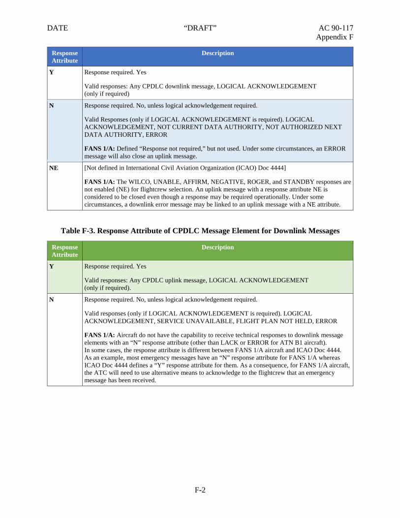
DATE “DRAFT” AC 90-117 Appendix F
Response Attribute
Description
Y Response required. Yes
Valid responses: Any CPDLC downlink message, LOGICAL ACKNOWLEDGEMENT (only if required)
N Response required. No, unless logical acknowledgement required.
Valid Responses (only if LOGICAL ACKNOWLEDGEMENT is required). LOGICAL ACKNOWLEDGEMENT, NOT CURRENT DATA AUTHORITY, NOT AUTHORIZED NEXT DATA AUTHORITY, ERROR
FANS 1/A: Defined “Response not required,” but not used. Under some circumstances, an ERROR message will also close an uplink message.
NE [Not defined in International Civil Aviation Organization (ICAO) Doc 4444]
FANS 1/A: The WILCO, UNABLE, AFFIRM, NEGATIVE, ROGER, and STANDBY responses are not enabled (NE) for flightcrew selection. An uplink message with a response attribute NE is considered to be closed even though a response may be required operationally. Under some circumstances, a downlink error message may be linked to an uplink message with a NE attribute.
Table F-3. Response Attribute of CPDLC Message Element for Downlink Messages
Response Attribute
Description
Y Response required. Yes
Valid responses: Any CPDLC uplink message, LOGICAL ACKNOWLEDGEMENT (only if required).
N Response required. No, unless logical acknowledgement required.
Valid responses (only if LOGICAL ACKNOWLEDGEMENT is required). LOGICAL ACKNOWLEDGEMENT, SERVICE UNAVAILABLE, FLIGHT PLAN NOT HELD, ERROR
FANS 1/A: Aircraft do not have the capability to receive technical responses to downlink message elements with an “N” response attribute (other than LACK or ERROR for ATN B1 aircraft). In some cases, the response attribute is different between FANS 1/A aircraft and ICAO Doc 4444. As an example, most emergency messages have an “N” response attribute for FANS 1/A whereas ICAO Doc 4444 defines a “Y” response attribute for them. As a consequence, for FANS 1/A aircraft, the ATC will need to use alternative means to acknowledge to the flightcrew that an emergency message has been received.
F-2
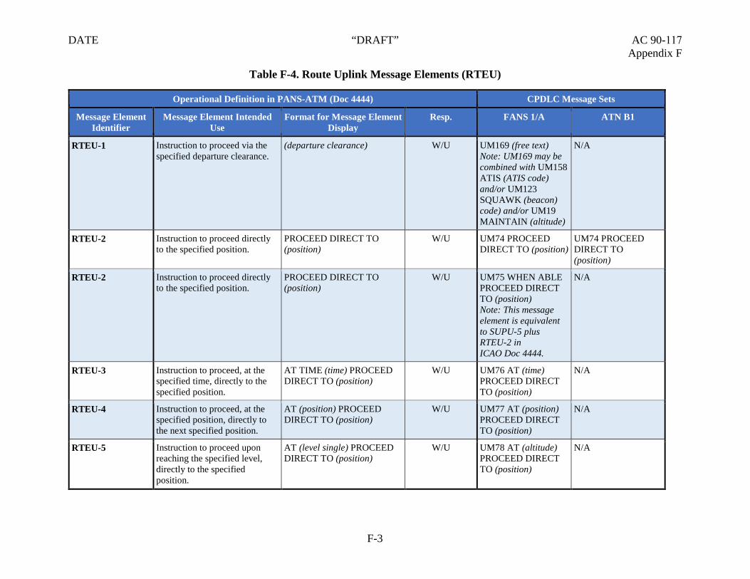
DATE “DRAFT” AC 90-117 Appendix F
Table F-4. Route Uplink Message Elements (RTEU)
Operational Definition in PANS-ATM (Doc 4444) CPDLC Message Sets
Message Element Identifier
Message Element Intended Use
Format for Message Element Display
Resp. FANS 1/A ATN B1
RTEU-1 Instruction to proceed via the specified departure clearance.
(departure clearance) W/U UM169 (free text) Note: UM169 may be combined with UM158 ATIS (ATIS code) and/or UM123 SQUAWK (beacon) code) and/or UM19 MAINTAIN (altitude)
N/A
RTEU-2 Instruction to proceed directly to the specified position.
PROCEED DIRECT TO (position)
W/U UM74 PROCEED DIRECT TO (position)
UM74 PROCEED DIRECT TO (position)
RTEU-2 Instruction to proceed directly to the specified position.
PROCEED DIRECT TO (position)
W/U UM75 WHEN ABLE PROCEED DIRECT TO (position) Note: This message element is equivalent to SUPU-5 plus RTEU-2 in ICAO Doc 4444.
N/A
RTEU-3 Instruction to proceed, at the specified time, directly to the specified position.
AT TIME (time) PROCEED DIRECT TO (position)
W/U UM76 AT (time) PROCEED DIRECT TO (position)
N/A
RTEU-4 Instruction to proceed, at the specified position, directly to the next specified position.
AT (position) PROCEED DIRECT TO (position)
W/U UM77 AT (position) PROCEED DIRECT TO (position)
N/A
RTEU-5 Instruction to proceed upon reaching the specified level, directly to the specified position.
AT (level single) PROCEED DIRECT TO (position)
W/U UM78 AT (altitude) PROCEED DIRECT TO (position)
N/A
F-3

DATE “DRAFT” AC 90-117 Appendix F
Operational Definition in PANS-ATM (Doc 4444) CPDLC Message Sets
Message Element Identifier
Message Element Intended Use
Format for Message Element Display
Resp. FANS 1/A ATN B1
RTEU-6 Instruction to proceed to the specified position via the specified route.
CLEARED TO (position) VIA (departure data[O]) (en-route data)
W/U UM79 CLEARED TO (position) VIA (route clearance)
UM79 CLEARED TO (position) VIA (route clearance)
RTEU-7 Instruction to proceed via the specified route.
CLEARED (departure data[O]) (en-route data) (arrival approach data)
W/U UM80 CLEARED (route clearance)
UM80 CLEARED (route clearance)
RTEU-8 Instruction to proceed in accordance with the specified procedure.
CLEARED (procedure name) W/U UM81 CLEARED (procedure name)
N/A
RTEU-9 Instruction to proceed from the specified position via the specified route.
AT (position) CLEARED (en-route data) (arrival approach data)
W/U UM83 AT (position) CLEARED (route clearance)
N/A
RTEU-10 Instruction to proceed from the specified position via the specified procedure.
AT (position) CLEARED (procedure name)
W/U UM84 AT (position) CLEARED (procedure name)
N/A
RTEU-11 Instruction to enter a holding pattern at the specified position in accordance with the specified instructions. Note: RTEU-13 EXPECT FURTHER CLEARANCE AT TIME (time) is appended to this message when an extended hold is anticipated.
AT (position) HOLD INBOUND TRACK (degrees)(direction) TURNS (leg type) LEGS
W/U UM91 HOLD AT (position) MAINTAIN (altitude) INBOUND TRACK (degrees) (direction) TURN LEG TIME (leg type)
N/A
F-4

DATE “DRAFT” AC 90-117 Appendix F
Operational Definition in PANS-ATM (Doc 4444) CPDLC Message Sets
Message Element Identifier
Message Element Intended Use
Format for Message Element Display
Resp. FANS 1/A ATN B1
RTEU-12 Instruction to enter a holding pattern at the specified position in accordance with the published holding instructions. Note: RTEU-13 EXPECT FURTHER CLEARANCE AT TIME (time) is appended to this message when an extended hold is anticipated.
AT (position) HOLD AS PUBLISHED
W/U UM92 HOLD AT (position) AS PUBLISHED MAINTAIN (altitude)
UM92 HOLD AT (position) AS PUBLISHED MAINTAIN (level)
RTEU-13 Notification that an onwards clearance may be issued at the specified time.
EXPECT FURTHER CLEARANCE AT TIME (time)
R UM93 EXPECT FURTHER CLEARANCE AT (time)
N/A
RTEU-14 Notification that a clearance may be issued for the aircraft to fly the specified procedure or clearance name.
EXPECT (named instruction) R UM99 EXPECT (procedure name) Note: Used when a published procedure is designated.
UM169 ‘EXPECT (clearance name)’ Note: Used when an unpublished clearance/procedure name is designated.
N/A
RTEU-15 Request to confirm the assigned route.
CONFIRM ASSIGNED ROUTE
Y UM137 CONFIRM ASSIGNED ROUTE Note: NE response attribute.
N/A
F-5

DATE “DRAFT” AC 90-117 Appendix F
Operational Definition in PANS-ATM (Doc 4444) CPDLC Message Sets
Message Element Identifier
Message Element Intended Use
Format for Message Element Display
Resp. FANS 1/A ATN B1
RTEU-16 Request to report.
make a position REQUEST POSITION REPORT
Y UM147 REQUEST POSITION REPORT
N/A
RTEU-17 Request to provide the estimated time of arrival at the specified position.
ADVISE ETA (position) Y UM169 ‘ADVISE ETA (position)’
N/A
F-6

DATE “DRAFT” AC 90-117 Appendix F
Table F-5. Route Downlink Message Elements (RTED)
Operational Definition in PANS-ATM (Doc 4444) CPDLC Message Sets
Message Element Identifier
Message Element Intended Use Format for Message Element Display
Resp. FANS 1/A ATN B1
RTED-1 Request for a direct clearance to the specified position.
REQUEST DIRECT TO (position)
Y DM22 REQUEST DIRECT TO (position)
DM22 REQUEST DIRECT TO (position)
RTED-2 Request for the specified procedure or clearance name.
REQUEST (named instruction) Y DM23 REQUEST (procedure name)
N/A
RTED-3 Request for the specified route. REQUEST CLEARANCE (departure data[O]) (en-route data) (arrival approach data[O])
Y DM24 REQUEST (route clearance)
N/A
RTED-4 Request for the specified clearance.
REQUEST (clearance type) CLEARANCE
Y DM25 REQUEST CLEARANCE
N/A
RTED-5 Position report. POSITION REPORT (position report)
N DM48 POSITION REPORT (position report)
N/A
RTED-6 Request for the specified heading.
REQUEST HEADING (degrees)
Y DM70 REQUEST HEADING (degrees)
N/A
RTED-7 Request for the specified ground track.
REQUEST GROUND TRACK (degrees)
Y DM71 REQUEST GROUND TRACK (degrees)
N/A
RTED-8 Request for the time or position that can be expected to rejoin the cleared route.
WHEN CAN WE EXPECT BACK ON ROUTE
Y DM51 WHEN CAN WE EXPECT BACK ON ROUTE
N/A
RTED-9 Confirmation that the assigned route is the specified route.
ASSIGNED ROUTE (departure data[O]) (en-route data) (arrival approach data[O])
N DM40 ASSIGNED ROUTE (route clearance)
N/A
RTED-10 Notification of estimated time of arrival at the specified position.
ETA (position) TIME (time) N DM67 ‘ETA (position) TIME (time)’
N/A
F-7

DATE “DRAFT” AC 90-117 Appendix F
Table F-6. Lateral Uplink Message Elements (LATU)
Operational Definition in PANS-ATM (Doc 4444) CPDLC Message Sets
Message Element Identifier
Message Element Intended Use
Format for Message Element Display
Resp. FANS 1/A ATN B1
LATU-1 Instruction to fly a parallel track to the cleared route at a displacement of the specified distance in the specified direction.
OFFSET (specified distance) (direction) OF ROUTE
W/U UM64 OFFSET (distance offset) (direction) OF ROUTE
UM64 OFFSET (specified distance) (direction) OF ROUTE
LATU-2 Instruction to fly a parallel track to the cleared route at a displacement of the specified distance in the specified direction and commencing at the specified position.
AT (position) OFFSET (specified distance) (direction) OF ROUTE
W/U UM65 AT (position) OFFSET (distance offset) (direction) OF ROUTE
N/A
LATU-3 Instruction to fly a parallel track to the cleared route at a displacement of the specified distance in the specified direction and commencing at the specified time.
AT TIME (time) OFFSET (specified distance) (direction) OF ROUTE
W/U UM66 AT (time) OFFSET (distance offset) (direction) OF ROUTE
N/A
LATU-4 Instruction to rejoin the cleared route.
REJOIN ROUTE W/U UM67 PROCEED BACK ON ROUTE
N/A
LATU-5 Instruction to rejoin the cleared route before passing the specified position.
REJOIN ROUTE BEFORE PASSING (position)
W/U UM68 REJOIN ROUTE BY (position)
N/A
LATU-6 Instruction to rejoin the cleared route before the specified time.
REJOIN ROUTE BEFORE TIME (time)
W/U UM69 REJOIN ROUTE BY (time)
N/A
LATU-7 Notification that a clearance may be issued to enable the aircraft to rejoin the cleared route before passing the specified position.
EXPECT BACK ON ROUTE BEFORE PASSING (position)
R UM70 EXPECT BACK ON ROUTE BY (position)
N/A
F-8

DATE “DRAFT” AC 90-117 Appendix F
Operational Definition in PANS-ATM (Doc 4444) CPDLC Message Sets
Message Element Identifier
Message Element Intended Use
Format for Message Element Display
Resp. FANS 1/A ATN B1
LATU-8 Notification a clearance may be issued to enable the aircraft to rejoin the cleared route before the specified time.
EXPECT BACK ON ROUTE BEFORE TIME (time)
R UM71 EXPECT BACK ON ROUTE BY (time)
N/A
LATU-9 Instruction to resume own navigation following a period of tracking or heading clearances. May be used in conjunction with an instruction on how or where to rejoin the cleared route.
RESUME OWN NAVIGATION
W/U UM72 RESUME OWN NAVIGATION
UM72 RESUME OWN NAVIGATION
LATU-10 Instruction allowing deviation up to the specified distance(s) from the cleared route in the specified direction(s).
CLEARED TO DEVIATE UP TO (lateral deviation) OF ROUTE
W/U UM82 CLEARED TO DEVIATE UP TO (distance offset) (direction) OF ROUTE
UM82 CLEARED TO DEVIATE UP TO (specified distance) (direction) OF ROUTE
LATU-11 Instruction to turn left or right as specified on to the specified heading.
TURN (direction) HEADING (degrees)
W/U UM94 TURN (direction) HEADING (degrees)
UM94 TURN (direction) HEADING (degrees)
LATU-11 Instruction to turn left or right as specified on to the specified heading.
TURN (direction) HEADING (degrees)
W/U UM98 IMMEDIATELY TURN (direction) HEADING (degrees) Note: This message element is equivalent to EMGU-2 plus LATU-11 in ICAO Doc 4444.
N/A
LATU-12 Instruction to turn left or right as specified on to the specified track.
TURN (direction) GROUND TRACK (degrees)
W/U UM95 TURN (direction) GROUND TRACK (degrees)
N/A
F-9

DATE “DRAFT” AC 90-117 Appendix F
Operational Definition in PANS-ATM (Doc 4444) CPDLC Message Sets
Message Element Identifier
Message Element Intended Use
Format for Message Element Display
Resp. FANS 1/A ATN B1
LATU-13 Instruction to turn the specified number of degrees left or right.
TURN (direction) (number of degrees) DEGREES
W/U N/A UM215 TURN (direction) (degrees)
LATU-14 Instruction to continue to fly the present heading.
CONTINUE PRESENT HEADING
W/U UM96 FLY PRESENT HEADING
UM96 CONTINUE PRESENT HEADING
LATU-15 Instruction to fly the specified heading upon reaching the specified position.
AT (position) FLY HEADING (degrees)
W/U UM97 AT (position) FLY HEADING (degrees)
N/A
LATU-16 Instruction to fly the specified heading.
FLY HEADING (degrees) W/U N/A UM190 FLY HEADING (degrees)
LATU-17 Instruction to report when clear of weather.
REPORT CLEAR OF WEATHER
W/U UM169 ‘REPORT CLEAR OF WEATHER’ Note: R response attribute.
N/A
LATU-18 Instruction to report when the aircraft is back on the cleared route.
REPORT BACK ON ROUTE W/U UM127 REPORT BACK ON ROUTE Note: R response attribute.
N/A
LATU-19 Instruction to report upon passing the specified position.
REPORT PASSING (position) W/U UM130 REPORT PASSING (position) Note: R response attribute.
N/A
F-10

DATE “DRAFT” AC 90-117 Appendix F
Table F-7. Lateral Downlink Message Elements (LATD)
Operational Definition in PANS-ATM (Doc 4444) CPDLC Message Sets
Message Element Identifier
Message Element Intended Use Format for Message Element Display
Resp. FANS 1/A ATN B1
LATD-1 Request for a parallel track from the cleared route at a displacement of the specified distance in the specified direction.
REQUEST OFFSET (specified distance) (direction) OF ROUTE
Y DM15 REQUEST OFFSET (specified distance) (direction) OF ROUTE
N/A
LATD-2 Request for a weather deviation up to the specified distance(s) off track in the specified direction(s).
REQUEST WEATHER DEVIATION UP TO (lateral deviation) OF ROUTE
Y DM27 REQUEST WEATHER DEVIATION UP TO (specified distance) (direction) OF ROUTE
DM27 REQUEST WEATHER DEVIATION UP TO (specified distance) (direction) OF ROUTE
LATD-3 Report indicating that the aircraft is clear of weather.
CLEAR OF WEATHER N DM69 ‘CLEAR OF WEATHER’
N/A
LATD-4 Report indicating that the cleared route has been rejoined.
BACK ON ROUTE N DM41 BACK ON ROUTE
N/A
LATD-5 Report indicating diverting to the specified position via the specified route, which may be sent without any previous coordination done with ATC.
DIVERTING TO (position) VIA (en-route data) (arrival approach data[O])
Y DM59 DIVERTING TO (position) VIA (route clearance) Note 1: H alert attribute. Note 2: N response attribute.
N/A
LATD-6 Report indicating that the aircraft is offsetting to a parallel track at the specified distance in the specified direction off from the cleared route.
OFFSETTING (specified distance) (direction) OF ROUTE
Y DM60 OFFSETTING (distance offset) (direction) OF ROUTE Note 1: H alert attribute. Note 2: N response attribute.
N/A
F-11

DATE “DRAFT” AC 90-117 Appendix F
Operational Definition in PANS-ATM (Doc 4444) CPDLC Message Sets
Message Element Identifier
Message Element Intended Use Format for Message Element Display
Resp. FANS 1/A ATN B1
LATD-7 Report indicating deviating specified distance or degrees in the specified direction from the cleared route.
DEVIATING (Specified Deviation) (direction) OF ROUTE
Y DM80 DEVIATING (Deviation Offset) (direction) OF ROUTE Note 1: H alert attribute. Note 2: N response attribute.
N/A
LATD-8 Report indicating passing the specified position.
PASSING (position) N DM31 PASSING (position)
N/A
F-12

DATE “DRAFT” AC 90-117 Appendix F
Table F-8. Level Uplink Message Elements (LVLU)
Operational Definition in PANS-ATM (Doc 4444) CPDLC Message Sets
Message Element Identifier
Message Element Intended Use
Format for Message Element Display
Resp. FANS 1/A ATN B1
LVLU-1 Notification that an instruction may be expected for the aircraft to commence climb at the specified time.
EXPECT HIGHER AT TIME (time)
R UM7 EXPECT CLIMB AT (time)
N/A
LVLU-2 Notification that an instruction may be expected for the aircraft to commence climb at the specified position.
EXPECT HIGHER AT (position)
R UM8 EXPECT CLIMB AT (position)
N/A
LVLU-3 Notification that an instruction may be expected for the aircraft to commence descent at the specified time.
EXPECT LOWER AT TIME (time)
R UM9 EXPECT DESCENT AT (time)
N/A
LVLU-4 Notification that an instruction may be expected for the aircraft to commence descent at the specified position.
EXPECT LOWER AT (position)
R UM10 EXPECT DESCENT AT (position)
N/A
LVLU-5 Instruction to maintain the specified level or vertical range.
MAINTAIN (level) W/U UM19 MAINTAIN (altitude) Note: Used for a single level.
UM30 MAINTAIN BLOCK (altitude) TO (altitude) Note: Used for a vertical range.
UM19 MAINTAIN (level)
F-13

DATE “DRAFT” AC 90-117 Appendix F
Operational Definition in PANS-ATM (Doc 4444) CPDLC Message Sets
Message Element Identifier
Message Element Intended Use
Format for Message Element Display
Resp. FANS 1/A ATN B1
LVLU-6 Instruction that a climb to the specified level or vertical range is to commence and once reached is to be maintained.
CLIMB TO (level) W/U UM20 CLIMB TO AND MAINTAIN (altitude) Note: Used for a single level.
UM31 CLIMB TO AND MAINTAIN BLOCK (altitude) TO (altitude) Note: Used for a vertical range.
UM20 CLIMB TO (level)
LVLU-6 Instruction that a climb to the specified level or vertical range is to commence and once reached is to be maintained.
CLIMB TO (level) W/U UM36 EXPEDITE CLIMB TO (altitude) Note: This message element is equivalent to SUPU-3 plus LVLU-6 in ICAO Doc 4444.
UM38 IMMEDIATELY CLIMB TO (altitude) Note: This message element is equivalent to EMGU-2 plus LVLU-6 in ICAO Doc 4444.
N/A
F-14

DATE “DRAFT” AC 90-117 Appendix F
Operational Definition in PANS-ATM (Doc 4444) CPDLC Message Sets
Message Element Identifier
Message Element Intended Use
Format for Message Element Display
Resp. FANS 1/A ATN B1
LVLU-7 Instruction that at the specified time a climb to the specified level or vertical range is to commence and once reached is to be maintained. Note: This message element would be preceded with LVLU-5 MAINTAIN (level), to prevent the premature execution of the instruction.
AT TIME (time) CLIMB TO (level)
W/U UM21 AT (time) CLIMB TO AND MAINTAIN (altitude) Note: A vertical range cannot be provided.
N/A
LVLU-8 Instruction that at the specified position a climb to the specified level or vertical range is to commence and once reached is to be maintained. Note: This message element would be preceded with LVLU-5 MAINTAIN (level), to prevent the premature execution of the instruction.
AT (position) CLIMB TO (level)
W/U UM22 AT (position) CLIMB TO AND MAINTAIN (altitude) Note: A vertical range cannot be provided.
N/A
LVLU-9 Instruction that a descent to the specified level or vertical range is to commence and once reached is to be maintained.
DESCEND TO (level) W/U UM23 DESCEND TO AND MAINTAIN (altitude) Note: Used for a single level.
UM23 DESCEND TO (level)
F-15

DATE “DRAFT” AC 90-117 Appendix F
Operational Definition in PANS-ATM (Doc 4444) CPDLC Message Sets
Message Element Identifier
Message Element Intended Use
Format for Message Element Display
Resp. FANS 1/A ATN B1
LVLU-9 Instruction that a descent to the specified level or vertical range is to commence and once reached is to be maintained.
DESCEND TO (level) W/U UM32 DESCEND TO AND MAINTAIN BLOCK (altitude) TO (altitude) Note: Used for a vertical range.
UM39 IMMEDIATELY DESCEND TO (altitude) Note: This message element is equivalent
N/A
to EMGU-2 plus.
LVLU-10 Instruction that at the specified time a descent to the specified level or vertical range is to commence and once reached is to be maintained.
AT TIME (time) DESCEND TO (level)
W/U UM24 AT (time) DESCEND TO AND MAINTAIN (altitude) Note: A vertical range cannot be provided.
N/A
LVLU-11 Instruction that at the specified position a descent to the specified level or vertical range is to commence and once reached is to be maintained.
AT (position) DESCEND TO (level)
W/U UM25 AT (position) DESCEND TO AND MAINTAIN (altitude) Note: A vertical range cannot be provided.
N/A
LVLU-12 Instruction that a climb is to be completed such that the specified level is reached before the specified time.
CLIMB TO REACH (level single) BEFORE TIME (time)
W/U UM26 CLIMB TO REACH (altitude) BY (time)
UM26 CLIMB TO REACH (level) BY (time)
LVLU-13 Instruction that a climb is to be completed such that the specified level is reached before passing the specified position.
CLIMB TO REACH (level single) BEFORE PASSING (position)
W/U UM27 CLIMB TO REACH (altitude) BY (position)
UM27 CLIMB TO REACH (level) BY (position)
F-16

DATE “DRAFT” AC 90-117 Appendix F
Operational Definition in PANS-ATM (Doc 4444) CPDLC Message Sets
Message Element Identifier
Message Element Intended Use
Format for Message Element Display
Resp. FANS 1/A ATN B1
LVLU-14 Instruction that a descent is to be completed such that the specified level is reached before the specified time.
DESCEND TO REACH (level single) BEFORE TIME (time)
W/U UM28 DESCEND TO REACH (altitude) BY (time)
UM28 DESCEND TO REACH (level) BY (time)
LVLU-15 Instruction that a descent is to be completed such that the specified level is reached before passing the specified position.
DESCEND TO REACH (level single) BEFORE PASSING (position)
W/U UM29 DESCEND TO REACH (altitude) BY (position)
UM29 DESCEND TO REACH (level) BY (position)
LVLU-16 Instruction to stop the climb at the specified level and, once reached, this level is to be maintained. The specified level will be below the previously assigned level. This instruction should only be issued when the controller can confirm that the previously assigned level has not yet been reached.
STOP CLIMB AT (level single)
W/U UM169 ‘STOP CLIMB AT (altitude)’ Note: R response attribute.
N/A
LVLU-17 Instruction to stop the descent at the specified level and, once reached, this level is to be maintained. The specified level will be above the previously assigned level. This instruction should only be issued when the controller can confirm that the previously assigned level has not yet been reached.
STOP DESCENT AT (level single)
W/U UM169 ‘STOP DESCENT AT (altitude)’ Note: R response attribute.
N/A
LVLU-18 Instruction to climb at the specified rate or greater.
CLIMB AT (vertical rate) OR GREATER
W/U UM171 CLIMB AT (vertical rate) MINIMUM
UM 171 CLIMB AT (vertical rate) MINIMUM
F-17

DATE “DRAFT” AC 90-117 Appendix F
Operational Definition in PANS-ATM (Doc 4444) CPDLC Message Sets
Message Element Identifier
Message Element Intended Use
Format for Message Element Display
Resp. FANS 1/A ATN B1
LVLU-19 Instruction to climb at the specified rate or less.
CLIMB AT (vertical rate) OR LESS
W/U UM172 CLIMB AT (vertical rate) MAXIMUM
UM172 CLIMB AT (vertical rate) MAXIMUM
LVLU-20 Instruction to descend at the specified rate or greater.
DESCEND AT (vertical rate) OR GREATER
W/U UM173 DESCEND AT (vertical rate) MINIMUM
UM173 DESCEND AT (vertical rate) MINIMUM
LVLU-21 Instruction to descend at the specified rate or less.
DESCEND AT (vertical rate) OR LESS
W/U UM174 DESCEND AT (vertical rate) MAXIMUM
UM174 DESCEND AT (vertical rate) MAXIMUM
LVLU-22 Notification that a clearance may be issued for the aircraft to commence a climb to the specified level at the specified number of minutes after departure.
EXPECT (level single) (number of minutes) AFTER DEPARTURE
R UM169 ‘EXPECT (level single) (number of minutes) AFTER DEPARTURE’
N/A
LVLU-23 Instruction to report upon leaving the specified level.
REPORT LEAVING (level single)
W/U UM128 REPORT LEAVING (altitude) Note: R response attribute.
N/A
LVLU-24 Instruction to report upon maintaining the specified level.
REPORT MAINTAINING (level single)
W/U UM129 REPORT LEVEL (altitude) Note: R response attribute.
N/A
LVLU-25 Instruction to report the present level.
REPORT PRESENT LEVEL Y N/A Note: Refer to A.6.
UM133 REPORT PRESENT LEVEL
LVLU-26 Instruction to report upon reaching the specified vertical range.
REPORT REACHING BLOCK (level single) TO (level single)
W/U UM180 REACHING BLOCK (altitude) TO (altitude) Note: R response attribute.
N/A
F-18

DATE “DRAFT” AC 90-117 Appendix F
Operational Definition in PANS-ATM (Doc 4444) CPDLC Message Sets
Message Element Identifier
Message Element Intended Use
Format for Message Element Display
Resp. FANS 1/A ATN B1
LVLU-27 Request to confirm the assigned level.
CONFIRM ASSIGNED LEVEL
Y UM135 CONFIRM ASSIGNED ALTITUDE Note: NE response attribute.
N/A
LVLU-28 Request to provide the preferred level.
ADVISE PREFERRED LEVEL
Y UM169 ‘ADVISE PREFERRED LEVEL’ Note: R response attribute.
UM231 STATE PREFERRED LEVEL
LVLU-29 Request to provide the preferred time and/or position to commence descent to the aerodrome of intended arrival.
ADVISE TOP OF DESCENT Y UM169 ‘ADVISE TOP OF DESCENT’ Note: R response attribute.
UM232 STATE TOP OF DESCENT
LVLU-30 Request for the earliest time or position when the specified level can be accepted.
WHEN CAN YOU ACCEPT (level single)
Y UM148 WHEN CAN YOU ACCEPT (altitude) Note: NE response attribute.
UM148 WHEN CAN YOU ACCEPT (level)
LVLU-31 Request to indicate whether or not the specified level can be accepted at the specified position.
CAN YOU ACCEPT (level single) AT (position)
A/N UM149 CAN YOU ACCEPT (altitude) AT (position)
N/A
LVLU-32 Request to indicate whether or not the specified level can be accepted at the specified time.
CAN YOU ACCEPT (level single) AT TIME (time)
A/N UM150 CAN YOU ACCEPT (altitude) AT (time)
N/A
LVLU-33 Instruction to expedite a descent to the specified level is to commence and once reached the specified level is to be maintained.
EXPEDITE DESCENT TO (level single)
W/U UM37 EXPEDITE DESCENT TO (altitude)
N/A
F-19

DATE “DRAFT” AC 90-117 Appendix F
Table F-9. Level Downlink Message Elements (LVLD)
Operational Definition in PANS-ATM (Doc 4444) CPDLC Message Sets
Message Element Identifier
Message Element Intended Use Format for Message Element Display
Resp. FANS 1/A ATN B1
LVLD-1 Request to fly at the specified level or vertical range.
REQUEST (level) Y DM6 REQUEST (altitude) Note: Used for a single level.
DM7 REQUEST BLOCK (altitude) TO (altitude) Note: Used for a vertical range.
DM6 REQUEST (level)
LVLD-2 Request for a climb to the specified level or vertical range.
REQUEST CLIMB TO (level) Y DM9 REQUEST CLIMB TO (altitude) Note: Use of DM7 REQUEST BLOCK (altitude) TO (altitude) to request to climb at a vertical range.
DM9 REQUEST CLIMB TO (level)
LVLD-3 Request for a descent to the specified level or vertical range.
REQUEST DESCENT TO (level)
Y DM10 REQUEST DESCENT TO (altitude) Note: Use of DM7 REQUEST BLOCK (altitude) TO (altitude) to request to descend at a vertical range.
DM10 REQUEST DESCENT TO (level)
F-20

DATE “DRAFT” AC 90-117 Appendix F
Operational Definition in PANS-ATM (Doc 4444) CPDLC Message Sets
Message Element Identifier
Message Element Intended Use Format for Message Element Display
Resp. FANS 1/A ATN B1
LVLD-4 Request for a climb/descent to the specified level or vertical range to commence at the specified position.
AT (position) REQUEST (level)
Y DM11 AT (position) REQUEST CLIMB TO (altitude) Note: A vertical range cannot be requested.
DM12 AT (position) REQUEST DESCENT TO (altitude) Note: A vertical range cannot be requested.
N/A
LVLD-5 Request for a climb/descent to the specified level or vertical range to commence at the specified time.
AT TIME (time) REQUEST (level)
Y DM13 AT TIME (time) REQUEST CLIMB TO (altitude) Note: A vertical range cannot be requested.
DM14 AT TIME (time) REQUEST DESCENT TO (altitude) Note: A vertical range cannot be requested.
N/A
LVLD-6 Request for the earliest time or position that a descent can be expected.
WHEN CAN WE EXPECT LOWER LEVEL
Y DM52 WHEN CAN WE EXPECT LOWER ALTITUDE
N/A
LVLD-7 Request for the earliest time or position that a climb can be expected.
WHEN CAN WE EXPECT HIGHER LEVEL
Y DM53 WHEN CAN WE EXPECT HIGHER ALTITUDE
N/A
LVLD-8 Report indicating leaving the specified level.
LEAVING (level single) N DM28 LEAVING (altitude)
N/A
LVLD-9 Report indicating that the specified level is being maintained.
MAINTAINING (level single) N DM37 LEVEL (altitude) N/A
F-21

DATE “DRAFT” AC 90-117 Appendix F
Operational Definition in PANS-ATM (Doc 4444) CPDLC Message Sets
Message Element Identifier
Message Element Intended Use Format for Message Element Display
Resp. FANS 1/A ATN B1
LVLD-10 Report indicating reaching the specified vertical range.
REACHING BLOCK (level single) TO (level single)
N DM76 REACHING BLOCK (altitude) TO (altitude)
N/A
LVLD-11 Confirmation that the assigned level or vertical range is the specified level or vertical range.
ASSIGNED LEVEL (level) N DM38 ASSIGNED ALTITUDE (altitude) Note: Used for a single level.
DM77 ASSIGNED BLOCK (altitude) TO (altitude) Note: Used for a vertical range.
DM38 ASSIGNED LEVEL (level)
LVLD-12 Report indicating that the aircraft’s preferred level is the specified level.
PREFERRED LEVEL (level single)
N DM67‘PREFERRED LEVEL (altitude)’ Note 1: Response to free text UM169 ‘ADVISE PREFERRED LEVEL’ Note 2: When pre-formatting of the downlink message is not available, the flightcrew can shorten to: FL (altitude).
DM106 PREFERRED LEVEL (level) Note A vertical range may be provided.
LVLD-13 Report indicating climbing to the specified level.
CLIMBING TO (level single) N DM29 CLIMBING TO (altitude)
N/A
F-22

DATE “DRAFT” AC 90-117 Appendix F
Operational Definition in PANS-ATM (Doc 4444) CPDLC Message Sets
Message Element Identifier
Message Element Intended Use Format for Message Element Display
Resp. FANS 1/A ATN B1
LVLD-14 Report indicating descending to the specified level.
DESCENDING TO (level single)
N DM30 DESCENDING TO (altitude) Note: N alert attribute.
DM61 DESCENDING TO (altitude) Note: Urgent alert attribute.
N/A
LVLD-15 Indication that the specified level can be accepted at the specified time.
WE CAN ACCEPT (level single) AT TIME (time)
N DM67 ‘WE CAN ACCEPT (altitude) AT TIME (time)’
DM81 WE CAN ACCEPT (level) AT (time) Note: A vertical range may be provided.
LVLD-16 Indication that the specified level can be accepted at the specified position.
WE CAN ACCEPT (level single) AT (position)
N DM67 ‘WE CAN ACCEPT (altitude) AT (position)’
N/A
LVLD-17 Indication that the specified level cannot be accepted.
WE CANNOT ACCEPT (level single)
N DM67. ‘WE CANNOT ACCEPT (altitude)’
DM82 WE CANNOT ACCEPT (level) Note: A vertical range may be provided.
LVLD-18 Notification of the preferred time and position to commence descent for approach.
TOP OF DESCENT (position) TIME (time)
N DM67 ‘TOP OF DESCENT (time)’ Note: When pre-formatting of the downlink message is not available, the flightcrew can shorten to: TOD (time).
DM109 TOP OF DESCENT (time)
LVLD-19 Notification of the present level. Present level (single level) N N/A Note: Refer to A.6.
DM32 PRESENT LEVEL (altitude)
F-23

DATE “DRAFT” AC 90-117 Appendix F
Table F-10. Crossing Constraint Uplink Messages (CSTU)
Operational Definition in PANS-ATM (Doc 4444) CPDLC Message Sets
Message Element Identifier
Message Element Intended Use
Format for Message Element Display
Resp. FANS 1/A ATN B1
CSTU-1 Instruction that the specified position is to be crossed at the specified level or within the specified vertical range.
CROSS (position) AT (level) W/U UM46 CROSS (position) AT (altitude) Note: Used for a single level.
UM46 CROSS (position) AT (level)
CSTU-1 Instruction that the specified position is to be crossed at the specified level or within the specified vertical range.
CROSS (position) AT (level) UM50 CROSS (position) BETWEEN (altitude) AND (altitude) Note: Used for a vertical range.
UM46 CROSS (position) AT (level)
CSTU-1 Instruction that the specified position is to be crossed at the specified level or within the specified vertical range.
CROSS (position) AT (level) W/U UM49 CROSS (position) AT AND MAINTAIN (altitude) Note 1: A vertical range cannot be provided. Note 2: This message element is equivalent to CSTU-1 plus LVLU-5 in ICAO Doc 4444.
N/A
CSTU-2 Instruction that the specified position is to be crossed at or above the specified level.
CROSS (position) AT OR ABOVE (level single)
W/U UM47 CROSS (position) AT OR ABOVE (altitude)
UM47 CROSS (position) AT OR ABOVE (level)
CSTU-3 Instruction that the specified position is to be crossed at or below the specified level.
CROSS (position) AT OR BELOW (level single)
W/U UM48 CROSS (position) AT OR BELOW (altitude)
UM48 CROSS (position) AT OR BELOW (level)
F-24

DATE “DRAFT” AC 90-117 Appendix F
Operational Definition in PANS-ATM (Doc 4444) CPDLC Message Sets
Message Element Identifier
Message Element Intended Use
Format for Message Element Display
Resp. FANS 1/A ATN B1
CSTU-4 Instruction that the specified position is to be crossed at the specified time.
CROSS (position) AT TIME (time)
W/U UM51 CROSS (position) AT (time)
UM51 CROSS (position) AT (time)
CSTU-5 Instruction that the specified position is to be crossed before the specified time.
CROSS (position) BEFORE TIME (time)
W/U UM52 CROSS (position) AT OR BEFORE (time)
UM52 CROSS (position) AT OR BEFORE (time)
CSTU-6 Instruction that the specified position is to be crossed after the specified time.
CROSS (position) AFTER TIME (time)
W/U UM53 CROSS (position) AT OR AFTER (time)
UM53 CROSS (position) AT OR AFTER (time)
CSTU-7 Instruction that the specified position is to be crossed between the specified times.
CROSS (position) BETWEEN TIME (time) AND TIME (time)
W/U UM54 CROSS (position) BETWEEN (time) AND (time)
UM54 CROSS (position) BETWEEN (time) AND (time)
CSTU-8 Instruction that the specified position is to be crossed at the specified speed.
CROSS (position) AT (speed) W/U UM55 CROSS (position) AT (speed)
UM55 CROSS (position) AT (speed)
CSTU-9 Instruction that the specified position is to be crossed at or less than the specified speed.
CROSS (position) AT (speed) OR LESS
W/U UM56 CROSS (position) AT OR LESS THAN (speed)
N/A
CSTU-10 Instruction that the specified position is to be crossed at or greater than the specified speed.
CROSS (position) AT (speed) OR GREATER
W/U UM57 CROSS (position) AT OR GREATER THAN (speed)
N/A
F-25

DATE “DRAFT” AC 90-117 Appendix F
Operational Definition in PANS-ATM (Doc 4444) CPDLC Message Sets
Message Element Identifier
Message Element Intended Use
Format for Message Element Display
Resp. FANS 1/A ATN B1
CSTU-11 Instruction that the specified position is to be crossed at the specified time and at the level or within the vertical range as specified.
CROSS (position) AT TIME (time) AT (level)
W/U UM58 CROSS (position) AT (time) AT (altitude) Note: A vertical range cannot be provided.
UM62 AT (time) CROSS (position) AT AND MAINTAIN (altitude) Note 1: A vertical range cannot be provided. Note 2: This message element is equivalent to CSTU-11 plus LVLU-5 in ICAO Doc 4444.
N/A
CSTU-12 Instruction that the specified position is to be crossed before the specified time and at the level or within the vertical range as specified.
CROSS (position) BEFORE TIME (time) AT (level)
W/U UM59 CROSS (position) AT OR BEFORE (time) AT (altitude) Note: A vertical range cannot be provided.
N/A
CSTU-13 Instruction that the specified position is to be crossed after the specified time and at the level or within the vertical range as specified.
CROSS (position) AFTER TIME (time) AT (level)
W/U UM60 CROSS (position) AT OR AFTER (time) AT (altitude) Note: A vertical range cannot be provided.
N/A
F-26

DATE “DRAFT” AC 90-117 Appendix F
Operational Definition in PANS-ATM (Doc 4444) CPDLC Message Sets
Message Element Identifier
Message Element Intended Use
Format for Message Element Display
Resp. FANS 1/A ATN B1
CSTU-14 Instruction that the specified position is to be crossed at the level or within the vertical range, as specified, and at the specified speed.
CROSS (position) AT (level) AT (speed)
W/U UM61 CROSS (position) AT AND MAINTAIN (altitude) AT (speed) Note 1: A vertical range cannot be provided. Note 2: This message element is equivalent to CSTU-14 plus LVLU-5 in ICAO Doc 4444.
UM61 CROSS (position) AT AND MAINTAIN (level) AT (speed)
CSTU-15 Instruction that the specified position is to be crossed at the specified time at the level or within the vertical range, as specified, and at the specified speed.
CROSS (position) AT TIME (time) AT (level) AT (speed)
W/U UM63 AT (time) CROSS (position) AT AND MAINTAIN (altitude) AT (speed) Note 1: A vertical range cannot be provided. Note 2: This message element is equivalent to CSTU-15 plus LVLU-5 in ICAO Doc 4444.
N/A
F-27

DATE “DRAFT” AC 90-117 Appendix F
Table F-11. Speed Uplink Messages (SPDU)
Operational Definition in PANS-ATM (Doc 4444) CPDLC Message Sets
Message Element Identifier
Message Element Intended Use
Format for Message Element Display
Resp. FANS 1/A ATN B1
SPDU-1 Notification that a speed instruction may be issued to take effect at the specified time.
EXPECT SPEED CHANGE AT TIME (time)
R UM100 AT (time) EXPECT (speed)
N/A
SPDU-2 Notification that a speed instruction may be issued to take effect at the specified position.
EXPECT SPEED CHANGE AT (position)
R UM101 AT (position) EXPECT (speed)
N/A
SPDU-3 Notification that a speed instruction may be issued to take effect at the specified level.
EXPECT SPEED CHANGE AT (level single)
R UM102 AT (altitude) EXPECT (speed)
N/A
SPDU-4 Instruction to maintain the specified speed.
MAINTAIN (speed) W/U UM106 MAINTAIN (speed)
UM106 MAINTAIN (speed)
SPDU-5 Instruction to maintain the present speed.
MAINTAIN PRESENT SPEED
W/U UM107 MAINTAIN PRESENT SPEED
UM107 MAINTAIN PRESENT SPEED
SPDU-6 Instruction to maintain the specified speed or a greater.
MAINTAIN (speed) OR GREATER
W/U UM108 MAINTAIN (speed) OR GREATER
UM108 MAINTAIN (speed) OR GREATER
SPDU-7 Instruction to maintain the specified speed or a less.
MAINTAIN (speed) OR LESS
W/U UM109 MAINTAIN (speed) OR LESS
UM109 MAINTAIN (speed) OR LESS
SPDU-8 Instruction to maintain the specified speed range.
MAINTAIN (speed) TO (speed)
W/U UM110 MAINTAIN (speed) TO (speed)
N/A
SPDU-9 Instruction that the present speed is to be increased to the specified speed and maintained until further advised.
INCREASE SPEED TO (speed)
W/U UM111 INCREASE SPEED TO (speed)
N/A
F-28

DATE “DRAFT” AC 90-117 Appendix F
Operational Definition in PANS-ATM (Doc 4444) CPDLC Message Sets
Message Element Identifier
Message Element Intended Use
Format for Message Element Display
Resp. FANS 1/A ATN B1
SPDU-10 Instruction that the present speed is to be increased to the specified speed or greater, and maintained at or above the specified speed until further advised.
INCREASE SPEED TO (speed) OR GREATER
W/U UM112 INCREASE SPEED TO (speed) OR GREATER
N/A
SPDU-11 Instruction that the present speed is to be reduced to the specified speed and maintained until further advised.
REDUCE SPEED TO (speed) W/U UM113 REDUCE SPEED TO (speed)
N/A
SPDU-12 Instruction that the present speed is to be reduced to the specified speed or less and maintained at or below the specified speed until further advised.
REDUCE SPEED TO (speed) OR LESS
W/U UM114 REDUCE SPEED TO (speed) OR LESS
N/A
SPDU-13 Instruction to resume a normal speed. The aircraft no longer needs to comply with a previously issued speed restriction.
RESUME NORMAL SPEED W/U UM116 RESUME NORMAL SPEED
UM116 RESUME NORMAL SPEED
SPDU-14 Indication that the preferred speed may be flown without restriction.
NO SPEED RESTRICTION R UM169 ‘NO SPEED RESTRICTION’
UM222 NO SPEED RESTRICTION
F-29

DATE “DRAFT” AC 90-117 Appendix F
Operational Definition in PANS-ATM (Doc 4444) CPDLC Message Sets
Message Element Identifier
Message Element Intended Use
Format for Message Element Display
Resp. FANS 1/A ATN B1
SPDU-15 Request to report the speed defined by the speed type(s).
REPORT (speed types) SPEED
Y UM134 CONFIRM SPEED Note: NE response attribute.
UM169 ‘REPORT GROUND SPEED’ Note 1: Used when the controller is requesting the flightcrew to report the present ground speed. Note 2: R response attribute.
N/A
SPDU-16 Request to confirm the assigned speed.
CONFIRM ASSIGNED SPEED
Y UM136 CONFIRM ASSIGNED SPEED Note: NE response attribute.
N/A
SPDU-17 Request for the earliest time or position when the specified speed can be accepted.
WHEN CAN YOU ACCEPT (speed)
Y UM151 WHEN CAN YOU ACCEPT (speed) Note: NE response attribute.
N/A
F-30

DATE “DRAFT” AC 90-117 Appendix F
Table F-12. Speed Downlink Messages (SPDD)
Operational Definition in PANS-ATM (Doc 4444) CPDLC Message Sets
Message Element Identifier
Message Element Intended Use Format for Message Element Display
Resp. FANS 1/A ATN B1
SPDD-1 Request for the specified speed. REQUEST (speed) Y DM18 REQUEST (speed)
DM18 REQUEST (speed)
SPDD-2 Request for the earliest time or position that the specified speed can be expected.
WHEN CAN WE EXPECT (speed)
Y DM49 WHEN CAN WE EXPECT (speed)
N/A
SPDD-3 Report indicating the speed defined by the specified speed types.
(speed types) SPEED (speed) N DM34 PRESENT SPEED (speed)
DM67 ‘GROUND SPEED (speed)’ Note 1: Used when the controller is requesting the flightcrew to report the present ground speed. Note 2: When pre-formatting of the downlink message is not available, the flightcrew can shorten togs (speed).
N/A
SPDD-4 Confirmation that the assigned speed is the specified speed.
ASSIGNED SPEED (speed) N DM39 ASSIGNED SPEED (speed)
N/A
SPDD-5 Indication that the specified speed can be accepted at the specified time.
WE CAN ACCEPT (speed) AT TIME (time)
N DM67 ‘WE CAN ACCEPT (speed) AT TIME (time)’
N/A
SPDD-6 Indication that the specified speed cannot be accepted.
WE CANNOT ACCEPT (speed)
N DM67 ‘WE CANNOT ACCEPT (speed)’
N/A
F-31

DATE “DRAFT” AC 90-117 Appendix F
Table F-13. Air Traffic Advisory Uplink Messages (ADVU)
Operational Definition in PANS-ATM (Doc 4444) CPDLC Message Sets
Message Element Identifier
Message Element Intended Use
Format for Message Element Display
Resp. FANS 1/A ATN B1
ADVU-1 Advisory providing the specified altimeter setting for the specified facility.
(facility designation) ALTIMETER (altimeter setting)
R UM153 ALTIMETER (altimeter) Note: The facility designation and the time of measurement cannot be provided.
UM169 ‘(facility designation) ALTIMETER (altimeter setting)’
UM213 (facility designation) ALTIMETER (altimeter) Note: The facility designation is always provided and the time of measurement cannot be provided.
ADVU-2 Advisory that the ATS surveillance service is terminated.
SURVEILLANCE SERVICE TERMINATED
R UM154 RADAR SERVICES TERMINATED
UM169 ‘SURVEILLANCE SERVICE TERMINATED’ Note: ATS advisory that the radar and/or ADS-B service is terminated.
N/A
ADVU-3 Advisory that ATS surveillance service has been established. A position may be specified position.
IDENTIFIED (position[O]) R UM155 RADAR CONTACT (position) Note: The provision of the position is required.
N/A
ADVU-4 Advisory that ATS surveillance contact has been lost.
IDENTIFICATION LOST R UM156 RADAR CONTACT LOST
N/A
F-32

DATE “DRAFT” AC 90-117 Appendix F
Operational Definition in PANS-ATM (Doc 4444) CPDLC Message Sets
Message Element Identifier
Message Element Intended Use
Format for Message Element Display
Resp. FANS 1/A ATN B1
ADVU-5 ATS advisory that the current ATIS code is as specified.
ATIS (ATIS code) R UM158 ATIS (ATIS code) Note: The airport is not provided.
N/A
ADVU-6 Advisory to request again with next ATC unit.
REQUEST AGAIN WITH NEXT ATC UNIT
N UM169 ‘REQUEST AGAIN WITH NEXT ATC UNIT’ Note: R response attribute.
UM237 REQUEST AGAIN WITH NEXT ATC UNIT
ADVU-7 Advisory of traffic significant to the flight.
TRAFFIC IS (traffic description)
R UM169 ‘TRAFFIC IS (traffic description)’
N/A
ADVU-8 Instruction to report that the specified traffic has been visually sighted and passed. The instruction may indicate the estimated time of passing.
REPORT SIGHTING AND PASSING OPPOSITE DIRECTION (aircraft type[O]) (traffic location) (ETP time[O])
W/U UM169 ‘REPORT SIGHTING AND PASSING OPPOSITE DIRECTION (traffic description) (ETP (time))’ Note: ETP Time is included when available.
N/A
ADVU-9 Instruction to select the specified SSR code.
SQUAWK (SSR code) W/U UM123 SQUAWK (beacon code)
UM123 SQUAWK (code)
ADVU-10 Instruction to disable SSR transponder responses.
STOP SQUAWK W/U UM124 STOP SQUAWK
N/A
ADVU-11 Instruction to stop ADS-B transmissions.
STOP ADS-B TRANSMISSION
W/U UM169 ‘STOP ADS-B TRANSMISSION’ Note: R response attribute.
N/A
ADVU-12 Instruction to include level information in the SSR transponder responses.
SQUAWK MODE C W/U UM125 SQUAWK ALTITUDE
N/A
F-33

DATE “DRAFT” AC 90-117 Appendix F
Operational Definition in PANS-ATM (Doc 4444) CPDLC Message Sets
Message Element Identifier
Message Element Intended Use
Format for Message Element Display
Resp. FANS 1/A ATN B1
ADVU-13 Instruction to stop including level information in the SSR transponder responses.
STOP SQUAWK MODE C W/U UM126 STOP ALTITUDE SQUAWK
N/A
ADVU-14 Request to confirm the selected SSR code.
CONFIRM SQUAWK CODE Y UM144 CONFIRM SQUAWK Note: NE response attribute.
N/A
ADVU-15 Instruction that the ‘ident’ function on the SSR transponder is to be actuated.
SQUAWK IDENT W/U UM179 SQUAWK IDENT
UM179 SQUAWK IDENT
ADVU-16 Instruction to activate the ADS-C capability.
ACTIVATE ADS-C W/U UM169 ‘ACTIVATE ADS C’ Note: R response attribute.
N/A
ADVU-17 Instruction to transmit voice position reports, as specified, due to ADS-C being out of service.
ADS-C OUT OF SERVICE REVERT TO VOICE POSITION REPORTS
W/U UM169 ‘ADS-C OUT OF SERVICE REVERT TO CPDLC POSITION REPORTS’
UM169 ‘ADS-C OUT OF SERVICE REVERT TO VOICE POSITION REPORTS’ Note: R response attribute.
N/A
ADVU-18 Instruction to intermediary aircraft to relay the specified message to the specified aircraft on the specified frequency, when provided.
RELAY TO (aircraft identification) (unit name) (relay text) (frequency[O])
W/U UM169 ‘RELAY TO (call sign) (unit name) (text of message to be relayed) ((frequency))’ Note 1: R response attribute.
N/A
F-34

DATE “DRAFT” AC 90-117 Appendix F
Operational Definition in PANS-ATM (Doc 4444) CPDLC Message Sets
Message Element Identifier
Message Element Intended Use
Format for Message Element Display
Resp. FANS 1/A ATN B1
Note 2: Frequency is included when available.
ADVU-19 Request to check the aircraft lateral position, level or speed, due to the ATC unit detecting a deviation from the clearance.
(deviation type) DEVIATION DETECTED. VERIFY AND ADVISE
W/U UM169 ‘LATERAL POSITION DEVIATION DETECTED. VERIFY AND ADVISE’
UM169 ‘LEVEL DEVIATION DETECTED. VERIFY AND ADVISE’
UM169 ‘SPEED DEVIATION DETECTED. VERIFY AND ADVISE’ Note: R response attribute.
N/A
ADVU-20 Notification that the CPDLC transfer is expected at the specified time.
EXPECT CPDLC TRANSFER AT TIME (time)
R UM 169 ‘EXPECT CPDLC TRANSFER AT TIME (time)’ Note: R response attribute.
N/A
ADVU-21 Notification that the first specified ATSU will not establish CPDLC and the NDA is expected to be the second specified ATSU.
CPDLC WITH (unit name) NOT REQUIRED EXPECT NEXT CPDLC FACILITY (unit name)
R UM 169 CPDLC WITH (unit name) NOT REQUIRED EXPECT NEXT CPDLC FACILITY (unit name) Note: R response attribute.
N/A
F-35

DATE “DRAFT” AC 90-117 Appendix F
Table F-14. Air Traffic Advisory Downlink Messages (ADVD)
Operational Definition in PANS-ATM (Doc 4444) CPDLC Message Sets
Message Element Identifier
Message Element Intended Use Format for Message Element Display
Resp. FANS 1/A ATN B1
ADVD-1 Report indicating that the aircraft is squawking the specified SSR code.
SQUAWKING (SSR code) N DM47 SQUAWKING (code)
N/A
ADVD-2 Report indicating that whether or not traffic has been visually sighted and if so, if it has been passed. May provide a description and/or location of the aircraft.
TRAFFIC (aircraft type[O]) (traffic location) (traffic visibility)
N DM67 ‘(traffic identification) SIGHTED AND PASSED’
DM67 ‘(traffic identification) NOT SIGHTED’
DM67 ‘TRAFFIC SIGHTED’
N/A
F-36

DATE “DRAFT” AC 90-117 Appendix F
Table F-15. Voice Communication Uplink Messages (COMU)
Operational Definition in PANS-ATM (Doc 4444) CPDLC Message Sets
Message Element Identifier
Message Element Intended Use
Format for Message Element Display
Resp. FANS 1/A ATN B1
COMU-1 Instruction to establish voice contact with the specified ATSU on the specified frequency.
CONTACT (unit name) (frequency)
W/U UM117 CONTACT (ICAO unit name) (frequency)
UM117 CONTACT (unit name) (frequency)
COMU-2 Instruction at the specified position, to establish voice contact with the specified ATSU on the specified frequency.
AT (position) CONTACT (unit name) (frequency)
W/U UM118 AT (position) CONTACT (ICAO unit name) (frequency)
N/A
COMU-3 Instruction at the specified time, to establish voice contact with the specified ATSU on the specified frequency.
AT TIME (time) CONTACT (unit name) (frequency)
W/U UM119 AT (time) CONTACT (ICAO unit name) (frequency)
N/A
COMU-4 Advisory of the secondary frequency.
SECONDARY FREQUENCY (frequency)
R UM169 ‘SECONDARY FREQUENCY (frequency)’
N/A
COMU-5 Instruction to monitor the specified ATSU on the specified frequency. The flightcrew is not required to establish voice contact on the frequency.
MONITOR (unit name) (frequency)
W/U UM120 MONITOR (ICAO unit name) (frequency)
UM120 MONITOR (unit name) (frequency)
COMU-6 Instruction at the specified position, to monitor the specified ATSU on the specified frequency. The flightcrew is not required to establish voice contact on the frequency.
AT (position) MONITOR (unit name) (frequency)
W/U UM121 AT (position) MONITOR (ICAO unit name) (frequency)
N/A
F-37

DATE “DRAFT” AC 90-117 Appendix F
Operational Definition in PANS-ATM (Doc 4444) CPDLC Message Sets
Message Element Identifier
Message Element Intended Use
Format for Message Element Display
Resp. FANS 1/A ATN B1
COMU-7 Instruction that at the specified time, to monitor the specified ATSU on the specified frequency. The flightcrew is not required to establish voice contact on the frequency.
AT TIME (time) MONITOR (unit name) (frequency)
W/U UM122 AT (time) MONITOR (ICAO unit name) (frequency)
N/A
COMU-8 Instruction to check the microphone due to detection of a continuous transmission on the specified frequency.
CHECK STUCK MICROPHONE (frequency)
N UM157 CHECK STUCK MICROPHONE (frequency) Note: R response attribute.
UM157 CHECK STUCK MICROPHONE (frequency)
COMU-9 Advisory of the name of the current ATC unit.
CURRENT ATC UNIT (unit name)
N N/A UM183 ‘CURRENT ATC UNIT (unit name)’
F-38

DATE “DRAFT” AC 90-117 Appendix F
Table F-16. Voice Communication Downlink Messages (COMD)
Operational Definition in PANS-ATM (Doc 4444) CPDLC Message Sets
Message Element Identifier
Message Element Intended Use Format for Message Element Display
Resp. FANS 1/A ATN B1
COMD-1 Request for voice contact on the specified frequency.
REQUEST VOICE CONTACT (frequency)
Y DM20 REQUEST VOICE CONTACT Note: Used when a frequency is not required.
DM21 REQUEST VOICE CONTACT (frequency) Note: Used when a frequency is required.
N/A
COMD-2 Notification from the intermediary aircraft of the specified response from the specified aircraft.
RELAY FROM (aircraft identification) (relayed text response)
N DM67 ‘RELAY FROM (call sign) (response parameters)’
N/A
F-39

DATE “DRAFT” AC 90-117 Appendix F
Table F-17. Spacing Uplink Messages (SPCU)
Operational Definition in PANS-ATM (Doc 4444) CPDLC Message Sets
Message Element Identifier
Message Element Intended Use
Format for Message Element Display
Resp. FANS 1/A ATN B1
SPCU-1 ATS acknowledgement for the pilot use of the in-trail procedure when the ITP aircraft is behind the reference aircraft. This message element is always concatenated with a vertical clearance.
ITP BEHIND (aircraft identification)
N UM169 ‘ITP BEHIND (aircraft identification)’ Note: R response attribute.
N/A
SPCU-2 ATS acknowledgement for the pilot use of the in-trail procedure when the ITP aircraft is ahead of the reference aircraft. This message element is always concatenated with a vertical clearance.
ITP AHEAD OF (aircraft identification)
N UM169 ‘ITP AHEAD OF (aircraft identification)’ Note: R response attribute.
N/A
SPCU-3 ATS acknowledgement for the pilot use of the in-trail procedure when the ITP aircraft is behind both reference aircraft. This message element is always concatenated with a vertical clearance.
ITP BEHIND (aircraft identification) AND BEHIND (aircraft identification)
N UM169 ‘ITP BEHIND (aircraft identification) AND BEHIND (aircraft identification)’ Note: R response attribute.
N/A
SPCU-4 ATS acknowledgement for the pilot use of the in-trail procedure when the ITP aircraft is ahead of both reference aircraft. This message element is always concatenated with a vertical clearance.
ITP AHEAD OF (aircraft identification) AND AHEAD OF (aircraft identification)
N UM169 ‘ITP AHEAD OF (aircraft identification) AND AHEAD OF (aircraft identification)’ Note: R response attribute.
N/A
F-40

DATE “DRAFT” AC 90-117 Appendix F
Operational Definition in PANS-ATM (Doc 4444) CPDLC Message Sets
Message Element Identifier
Message Element Intended Use
Format for Message Element Display
Resp. FANS 1/A ATN B1
SPCU-5 ATS acknowledgement for the pilot use of the in-trail procedure when the ITP aircraft is behind one reference aircraft and ahead of one reference aircraft. This message element is always concatenated with a vertical clearance.
ITP BEHIND (aircraft identification) AND AHEAD OF (aircraft identification)
N UM169 ‘ITP BEHIND (aircraft identification) AND AHEAD OF (aircraft identification)’ Note: R response attribute.
N/A
F-41

DATE “DRAFT” AC 90-117 Appendix F
Table F-18. Spacing Downlink Messages (SPCD)
Operational Definition in PANS-ATM (Doc 4444) CPDLC Message Sets
Message Element Identifier
Message Element Intended Use Format for Message Element Display
Resp. FANS 1/A ATN B1
SPCD-1 Advisory indicating that the pilot has the ITP equipment, and provides the specified distance to the reference aircraft, including aircraft identification. This message element is always concatenated with a vertical request.
ITP (specified distance) BEHIND (aircraft identification)
N DM67 ‘ITP (distance) BEHIND (aircraft identification)’
N/A
SPCD-2 Advisory indicating that the pilot has the ITP equipment, and provides the specified distance from the reference aircraft, including aircraft identification. This message element is always concatenated with a vertical request.
ITP (specified distance) AHEAD OF (aircraft identification)
N DM67 ‘ITP (distance) AHEAD OF (aircraft identification)’
N/A
SPCD-3 Advisory indicating that the pilot has the ITP equipment, and provides the specified distance to both reference aircraft, including aircraft identification. This message element is always concatenated with a vertical request.
ITP (specified distance) BEHIND (aircraft identification) AND (specified distance) BEHIND (aircraft identification)
N DM67 ‘ITP (distance) BEHIND (aircraft identification) AND (distance) BEHIND (aircraft identification')’ Note: Used with a vertical request, indicating an ITP request when there are two reference aircraft, both behind.
N/A
F-42

DATE “DRAFT” AC 90-117 Appendix F
Operational Definition in PANS-ATM (Doc 4444) CPDLC Message Sets
Message Element Identifier
Message Element Intended Use Format for Message Element Display
Resp. FANS 1/A ATN B1
SPCD-4 Advisory indicating that the pilot has the ITP equipment, and provides the specified distance from both reference aircraft, including aircraft identification. This message element is always concatenated with a vertical request.
ITP (specified distance) AHEAD OF (aircraft identification) AND (specified distance) AHEAD OF (aircraft identification)
N DM67 ‘ITP (distance) AHEAD OF (aircraft identification) AND (distance) AHEAD OF (aircraft identification)’ Note: Used with a vertical request, indicating an ITP request when there are two reference aircraft, both ahead.
N/A
SPCD-5 Advisory indicating that the pilot has the ITP equipment, and provides the specified distance to one reference aircraft and the specified distance from another reference aircraft, including aircraft identification. This message element is always concatenated with a vertical request.
ITP (specified distance) BEHIND (aircraft identification) AND (specified distance) AHEAD OF (aircraft identification)
N DM67 ‘ITP (distance) BEHIND (aircraft identification) AND (distance) AHEAD OF (aircraft identification)’ Note: Used with a vertical request, indicating an ITP request when there are two reference aircraft, one behind and the other ahead.
N/A
F-43

DATE “DRAFT” AC 90-117 Appendix F
Table F-19. Emergency/Urgency Uplink Messages (EMGU)
Operational Definition in PANS-ATM (Doc 4444) CPDLC Message Sets
Message Element Identifier
Message Element Intended Use
Format for Message Element Display
Resp. FANS 1/A ATN B1
EMGU-1 Request to provide the fuel remaining (time) and the number of persons on board.
REPORT ENDURANCE AND PERSONS ON BOARD
Y UM131 REPORT REMAINING FUEL AND SOULS ON BOARD Note: NE response attribute.
N/A
EMGU-2 Instruction to immediately comply with the associated instruction to avoid imminent situation.
IMMEDIATELY N Used in combination with LVLU-6 and LVLU-9, which is implemented in FANS 1/A as: UM38 IMMEDIATELY CLIMB TO (altitude) UM39 IMMEDIATELY DESCEND TO (altitude)
N/A
EMGU-3 Request to confirm an ADS- C indicated emergency.
CONFIRM ADS-C EMERGENCY
A/N UM169 ‘CONFIRM ADS-C EMERGENCY’ Note: R response attribute.
N/A
F-44

DATE “DRAFT” AC 90-117 Appendix F
Table F-20. Emergency/Urgency Downlink Messages (EMGD)
Operational Definition in PANS-ATM (Doc 4444) CPDLC Message Sets
Message Element Identifier
Message Element Intended Use Format for Message Element Display
Resp. FANS 1/A ATN B1
EMGD-1 Indication of an urgent situation. PAN PAN PAN Y DM55 PAN PAN PAN Note: N response attribute.
N/A
EMGD-2 Indication of an emergency situation.
MAYDAY MAYDAY MAYDAY
Y DM56 MAYDAY MAYDAY MAYDAY Note: N response attribute.
N/A
EMGD-3 Report indicating fuel remaining (time) and number of persons on board.
(remaining fuel) ENDURANCE AND (persons on board) PERSONS ON BOARD
Y DM57 (remaining fuel) OF FUEL REMAINING AND (remaining souls) SOULS ON BOARD Note: N response attribute.
N/A
EMGD-4 Indication that the emergency situation is cancelled.
CANCEL EMERGENCY Y DM58 CANCEL EMERGENCY Note: N response attribute.
N/A
F-45

DATE “DRAFT” AC 90-117 Appendix F
Table F-21. Standard Response Uplink Messages (RSPU)
Operational Definition in PANS-ATM (Doc 4444) CPDLC Message Sets
Message Element Identifier
Message Element Intended Use
Format for Message Element Display
Resp. FANS 1/A ATN B1
RSPU-1 Indication that the message cannot be complied with.
UNABLE N UM0 UNABLE UM0 UNABLE
RSPU-2 Indication that the message will be responded to shortly.
STANDBY N UM1 STANDBY UM1 STANDBY
RSPU-3 Indication that a long term delay in response can be expected.
REQUEST DEFERRED N UM2 REQUEST DEFERRED
N/A
RSPU-4 Indication that the message is received.
ROGER N UM3 ROGER
UM169 ‘ROGER MAYDAY’ Note 1: R response attribute. Note 2: Used to acknowledge emergency downlink reports.
UM169 ‘ROGER PAN’ Note 1: R response attribute. Note 2: Used to acknowledge urgency downlink reports.
UM3 ROGER
RSPU-5 Indication that ATC is responding positively to the message.
AFFIRM N UM4 AFFIRM UM4 AFFIRM
RSPU-6 Indication that ATC is responding negatively to the message.
NEGATIVE N UM5 NEGATIVE UM5 NEGATIVE
F-46

DATE “DRAFT” AC 90-117 Appendix F
Operational Definition in PANS-ATM (Doc 4444) CPDLC Message Sets
Message Element Identifier
Message Element Intended Use
Format for Message Element Display
Resp. FANS 1/A ATN B1
RSPU-7 Indication that the request has been forwarded to the next control unit.
REQUEST FORWARDED N UM169 ‘REQUEST FORWARDED’ Note: R response attribute.
UM211 REQUEST FORWARDED
RSPU-8 Request to confirm the referenced request since the initial request was not understood. The request should be clarified and resubmitted.
CONFIRM REQUEST N UM143 CONFIRM REQUEST
N/A
Table F-22. Standard Response Downlink Messages (RSPD)
Operational Definition in PANS-ATM (Doc 4444) CPDLC Message Sets
Message Element Identifier
Message Element Intended Use Format for Message Element Display
Resp. FANS 1/A ATN B1
RSPD-1 Indication that the instruction is understood and will be complied with.
WILCO N DM0 WILCO DM0 WILCO
RSPD-2 Indication that the instruction cannot be complied with.
UNABLE N DM1 UNABLE DM1 UNABLE
RSPD-3 Indication that the message will be responded to shortly.
STANDBY N DM2 STANDBY DM2 STANDBY
RSPD-4 Indication that the message is received.
ROGER N DM3 ROGER Note: ROGER is the only correct response to an uplink free text message.
DM3 ROGER
RSPD-5 Indication of a positive response to a message.
AFFIRM N DM4 AFFIRM DM4 AFFIRM
RSPD-6 Indication of a negative response to a message.
NEGATIVE N DM5 NEGATIVE DM5 NEGATIVE
F-47

DATE “DRAFT” AC 90-117 Appendix F
Table F-23. Supplemental Uplink Messages (SUPU)
Operational Definition in PANS-ATM (Doc 4444) CPDLC Message Sets
Message Element Identifier
Message Element Intended Use
Format for Message Element Display
Resp. FANS 1/A ATN B1
SUPU-1 Indication that the associated instruction is to be executed when the flightcrew is ready.
WHEN READY N UM164 WHEN READY
N/A
SUPU-2 Indication that the associated message is issued due to the specified reason.
DUE TO (specified reason uplink)
N UM166 DUE TO TRAFFIC
UM167 DUE TO AIRSPACE RESTRICTION
N/A
SUPU-3 Instruction to execute the associated instruction at the aircraft’s best performance rate.
EXPEDITE N Used in combination with LVLU-6, which is implemented in FANS 1/A as: UM36 EXPEDITE CLIMB TO (altitude).
N/A
SUPU-4 Indication that the associated instruction is either a revision to a previously issued instruction or is different from the requested clearance.
REVISED (revision reason[O])
N UM170 ‘REVISED (revision reason[O])’ Note: R response attribute.
N/A
SUPU-5 Indication that the associated instruction is to be executed at the earliest point when the flightcrew is able.
WHEN ABLE N N/A Note: This message element is part of UM75.
N/A
F-48

DATE “DRAFT” AC 90-117 Appendix F
Table F-24. Supplemental Downlink Messages (SUPD)
Operational Definition in PANS-ATM (Doc 4444) CPDLC Message Sets
Message Element Identifier
Message Element Intended Use Format for Message Element Display
Resp. FANS 1/A ATN B1
SUPD-1 Indication that the associated message is issued due to specified reason.
DUE TO (specified reason downlink)
N DM65 DUE TO WEATHER
DM65 DUE TO WEATHER
SUPD-1 Indication that the associated message is issued due to specified reason.
DUE TO (specified reason downlink)
N DM66 DUE TO AIRCRAFT PERFORMANCE
DM66 DUE TO AIRCRAFT PERFORMANCE
Table F-25. Free Text Uplink Messages (TXTU)
Operational Definition in PANS-ATM (Doc 4444) CPDLC Message Sets
Message Element Identifier
Message Element Intended Use
Format for Message Element Display
Resp. FANS 1/A ATN B1
TXTU-1 (free text) Note: M alert attribute.
R UM169 (free text) UM203 (free text)
TXTU-2 (free text) Note: M alert attribute.
N UM169 (free text) Note: R response attribute.
UM183 (free text)
TXTU-3 (free text) Note: N alert attribute.
N UM169 (free text) Note: R response attribute.
N/A
TXTU-4 (free text) Note: M alert attribute.
W/U UM169 (free text) Note: R response attribute.
UM196 (free text)
TXTU-5 (free text) Note: M alert attribute.
A/N UM169 (free text) Note: R response attribute.
UM205 (free text)
F-49

DATE “DRAFT” AC 90-117 Appendix F
Table F-26. Free Text Downlink Messages (TXTD)
Operational Definition in PANS-ATM (Doc 4444) CPDLC Message Sets
Message Element Identifier
Message Element Intended Use Format for Message Element Display
Resp. FANS 1/A ATN B1
TXTD-1 (free text) Note: M alert attribute.
Y DM68 (free text) Note 1: Urgency or Distress Alr (M). Note 2: Selecting any of the emergency message elements will result in this message element being enabled for the flightcrew to include in the emergency message at their discretion.
N/A
TXTD-2 (free text) Note: M alert attribute.
N DM67 (free text) DM98 (free text)
F-50

DATE “DRAFT” AC 90-117 Appendix F
Table F-27. System Management Uplink Messages (SYSU)
Operational Definition in PANS-ATM (Doc 4444) CPDLC Message Sets
Message Element Identifier
Message Element Intended Use
Format for Message Element Display
Resp. FANS 1/A ATN B1
SYSU-1 System-generated notification of an error.
ERROR (error information) N UM159 ERROR (error information)
UM159 ERROR (error information)
SYSU-2 System-generated notification of the next data authority or the cancellation thereof.
NEXT DATA AUTHORITY (facility designation[O])
N UM160 NEXT DATA AUTHORITY (ICAO facility designation) Note: The facility designation is required.
UM160 NEXT DATA AUTHORITY (facility) Note: Facility parameter can specify a facility designation or no facility.
SYSU-3 System-generated notification that received message is not supported.
MESSAGE NOT SUPPORTED BY THIS ATC UNIT
N UM169 ‘MESSAGE NOT SUPPORTED BY THIS ATC UNIT’ Note: R response attribute.
UM162 MESSAGE NOT SUPPORTED BY THIS ATS UNIT
SYSU-4 System-generated notification that the received is acceptable for display.
LOGICAL ACKNOWLEDGEMENT
N N/A UM227 LOGICAL ACKNOWLEDGEMENT
SYSU-5 System-generated message indicating that requests for logical acknowledgements are not permitted.
USE OF LOGICAL ACKNOWLEDGEMENT PROHIBITED
N N/A UM233 USE OF LOGICAL ACKNOWLEDGEMENT PROHIBITED Note: ATN B1 ground systems may not use UM (as par ETSI CS) since the use of LACK is required.
F-51

DATE “DRAFT” AC 90-117 Appendix F
Operational Definition in PANS-ATM (Doc 4444) CPDLC Message Sets
Message Element Identifier
Message Element Intended Use
Format for Message Element Display
Resp. FANS 1/A ATN B1
SYSU-6 Advisory providing the maximum one-way uplink message transmission delay.
LATENCY TIME VALUE (latency value)
N UM169 ‘SET MAX UPLINK DELAY VALUE TO (delayed message parameter) SECONDS’ Note 1: R response attribute. Note 2: On FANS 1/A aircraft, this message requires specific action from the flightcrew to manually set the latency value.
N/A
SYSU-7 Indication that the received message has a latency greater than the requirement.
MESSAGE RECEIVED TOO LATE, RESEND MESSAGE OR CONTACT BY VOICE
N N/A UM159 ERROR (error information) + UM183 ‘DOWNLINK DELAYED USE – VOICE’ Note: The error information is set to the value (2).
F-52

DATE “DRAFT” AC 90-117 Appendix F
Table F-28. System Management Downlink Messages (SYSD)
Operational Definition in PANS-ATM (Doc 4444) CPDLC Message Sets
Message Element Identifier
Message Element Intended Use
Format for Message Element Display
Resp. FANS 1/A ATN B1
SYSD-1 System-generated notification of an error.
ERROR (error information) N DM62 ERROR (error information)
DM62 ERROR (error information)
SYSD-2 System-generated notification that the received message is acceptable for display.
LOGICAL ACKNOWLEDGEMENT
N N/A DM100 LOGICAL ACKNOWLEDGEMENT
SYSD-3 System-generated rejection of any CPDLC message sent from a ground facility that is not the current data authority.
NOT CURRENT DATA AUTHORITY
N DM63 NOT CURRENT DATA AUTHORITY
DM63 NOT CURRENT DATA AUTHORITY
SYSD-4 System-generated notification that the ground facility is now the current data authority.
CURRENT DATA AUTHORITY
N N/A DM99 CURRENT DATA AUTHORITY
SYSD-5 System-generated notification that the ground system is not designated as the next data authority (NDA), indicating the identity of the Current Data Authority. Identity of the Next Data Authority, if any, is also reported.
NOT AUTHORIZED NEXT DATA AUTHORITY (facility designation) (facility designation[O])
N DM64 (ICAO facility designation) Note: Use by FANS 1/A aircraft in B1 environments.
DM107 NOT AUTHORIZED NEXT DATA AUTHORITY Note: CDA and NDA cannot be provided.
SYSD-6 Indication that the received message has a latency greater than the requirement.
MESSAGE RECEIVED TOO LATE, RESEND MESSAGE OR CONTACT BY VOICE
N DM67 ‘MESSAGE RECEIVED TOO LATE, RESEND MESSAGE OR CONTACT BY VOICE’ Note: Sent with DM62.
DM 98 ‘MESSAGE RECEIVED TOO LATE, RESEND MESSAGE OR CONTACT BY VOICE’ Note: Sent with DM62.
SYSD-7 System-generated notification that the aircraft is in the inhibited state.
AIRCRAFT CPDLC INHIBITED
N N/A DM 98 ‘AIRCRAFT CPDLC INHIBITED'
F-53

DATE “DRAFT” AC 90-117 Appendix F
Table F-29. FANS 1/A Uplink Messages Not Recommended for Use
Message Element Justification
UM49 CROSS (position) AT AND MAINTAIN (altitude) Avoid use of this message due to inability of aircraft automation to maintain the altitude restriction.
UM62 AT (time) CROSS (position) AT AND MAINTAIN (altitude) Avoid use of this message due to inability of aircraft automation to maintain the altitude restriction.
UM85 EXPECT (route clearance) Avoid use of this message element due to potential misinterpretation.
UM86 AT (position) EXPECT (route clearance) Avoid use of this message element due to potential misinterpretation.
UM87 EXPECT DIRECT TO (position) Avoid use of this message element due to potential misinterpretation.
UM88 AT (position) EXPECT DIRECT TO (position) Avoid use of this message element due to potential misinterpretation.
UM89 AT (time) EXPECT DIRECT TO (position) Avoid use of this message element due to potential misinterpretation.
UM90 AT (altitude) EXPECT DIRECT TO (position) Avoid use of this message element due to potential misinterpretation.
UM162 SERVICE UNAVAILABLE Avoid use of this message element due to potential misinterpretation.
UM6 EXPECT (altitude) Avoid use of this message element due to potential misinterpretation.
UM11 EXPECT CRUISE CLIMB AT (time) Avoid use of this message element due to potential misinterpretation.
UM12 EXPECT CRUISE CLIMB AT (position) Avoid use of this message element due to potential misinterpretation.
UM13 AT (time) EXPECT CLIMB TO (altitude) Avoid use of this message element due to potential misinterpretation.
UM14 AT (position) EXPECT CLIMB TO (altitude) Avoid use of this message element due to potential misinterpretation.
UM15 AT (time) EXPECT DESCENT TO (altitude) Avoid use of this message element due to potential misinterpretation.
UM16 AT (position) EXPECT DESCENT TO (altitude) Avoid use of this message element due to potential misinterpretation.
UM17 AT (time) EXPECT CRUISE CLIMB TO (altitude) Avoid use of this message element due to potential misinterpretation.
UM49 CROSS (position) AT AND MAINTAIN (altitude) Avoid use of this message element due to potential misinterpretation.
UM62 AT (time) CROSS (position) AT AND MAINTAIN (altitude) Avoid use of this message element due to potential misinterpretation.
UM18 AT (position) EXPECT CRUISE CLIMB TO (altitude) Avoid use of this message element due to potential misinterpretation.
UM33 CRUISE (altitude) Avoid use of this message element due to potential misinterpretation.
UM34 CRUISE CLIMB TO (altitude) Avoid use of this message element due to potential misinterpretation.
F-54

DATE “DRAFT” AC 90-117 Appendix F
Message Element Justification
UM35 CRUISE CLIMB ABOVE (altitude) Avoid use of this message element due to potential misinterpretation.
UM40 IMMEDIATELY STOP CLIMB AT (altitude) Avoid use of this message element due to potential misinterpretation.
UM41 IMMEDIATELY STOP DESCENT AT (altitude) Avoid use of this message element due to potential misinterpretation.
UM175 REPORT REACHING (altitude) Avoid use of this message element due to potential misinterpretation.
UM42 EXPECT TO CROSS (position) AT (altitude) Avoid use of this message element due to potential misinterpretation.
UM43 EXPECT TO CROSS (position) AT OR ABOVE (altitude) Avoid use of this message element due to potential misinterpretation.
UM44 EXPECT TO CROSS (position) AT OR BELOW (altitude) Avoid use of this message element due to potential misinterpretation.
UM45 EXPECT TO CROSS (position) AT AND MAINTAIN (altitude) Avoid use of this message element due to potential misinterpretation.
UM103 AT (time) EXPECT (speed) TO (speed) Avoid use of this message element due to potential misinterpretation.
UM104 AT (position) EXPECT (speed) TO (speed) Avoid use of this message element due to potential misinterpretation.
UM105 AT (altitude) EXPECT (speed) TO (speed) Avoid use of this message element due to potential misinterpretation.
UM165 THEN Avoid use of this message element due to potential misinterpretation.
UM235 ROGER 7500 Avoid use of this message element due to potential misinterpretation.
UM168 DISREGARD Not operationally required. Note: These messages have been excluded from future B2 implementation
UM176 MAINTAIN OWN SEPARATION AND VMC Not operationally required. Note: These messages have been excluded from future B2 implementation
UM152 WHEN CAN YOU ACCEPT (specified distance) (direction) OFFSET Not operationally required. Note: These messages have been excluded from future B2 implementation
UM115 DO NOT EXCEED (speed) Not operationally required. Note: These messages have been excluded from future B2 implementation
UM182 CONFIRM ATIS CODE Not operationally required. Note: These messages have been excluded from future B2 implementation
UM169 ‘TRANSMIT ADS-B IDENT’ Use of SQUAWK IDENT is recommended.
UM169 ‘IDENTIFICATION TERMINATED’ Use of SURVEILLANCE SERVICE TERMINATED is recommended.
UM132 CONFIRM POSITION Use of ADS-C is recommended.
UM133 CONFIRM ALTITUDE Use of ADS-C is recommended.
F-55

DATE “DRAFT” AC 90-117 Appendix F
Message Element Justification
UM138 CONFIRM TIME OVER REPORTED WAYPOINT. Use of ADS-C is recommended.
UM139 CONFIRM REPORTED WAYPOINT Use of ADS-C is recommended.
UM140 CONFIRM NEXT WAYPOINT Use of ADS-C is recommended.
UM141 CONFIRM NEXT WAYPOINT ETA. Use of ADS-C is recommended.
UM142 CONFIRM ENSUING WAYPOINT Use of ADS-C is recommended.
UM146 REPORT GROUND TRACK Use of ADS-C is recommended.
UM181 REPORT DISTANCE (to/from) (position) Use of ADS-C is recommended.
UM145 CONFIRM HEADING Use of ADS-C is recommended.
UM177 AT PILOTS DISCRETION Not globally accepted. In airspace managed by the United States, when the controller issues UM177 AT PILOTS DISCRETION in conjunction with altitude assignments, the associated instruction to climb or descend may be executed when convenient and at any preferred rate. The aircraft may temporarily maintain intermediate levels but once the aircraft has vacated a level it may not return to that level.
F-56

DATE “DRAFT” AC 90-117 Appendix F
Table F-30. FANS 1/A Downlink Messages Not Recommended for Use
Message Element Justification
DM69 REQUEST VMC DESCENT Avoid use of this message element due to potential misinterpretation
DM75 AT PILOTS DISCRETION Avoid use of this message element due to potential misinterpretation
DM 67 ‘WHEN CAN WE EXPECT DESCENT TO (altitude)’ Avoid use of this message due to potential misinterpretation of subsequent response. Use of LVLD-6 WHEN CAN WE EXPECT HIGHER LEVEL and LVLD-7 WHEN CAN WE LOWER HIGHER LEVEL is recommended.
DM67 ‘WHEN CAN WE EXPECT CLIMB TO (altitude)’ Avoid use of this message due to potential misinterpretation of subsequent response. Use of LVLD-6 WHEN CAN WE EXPECT HIGHER LEVEL and LVLD-7 WHEN CAN WE LOWER HIGHER LEVEL is recommended.
DM74 REQUEST TO MAINTAIN OWN SEPARATION AND VMC Not operationally required. Note: These messages have been excluded from future B2 implementation.
DM8 REQUEST CRUISE CLIMB TO (altitude) Not operationally required. Note: These messages have been excluded from future B2 implementation.
DM54 WHEN CAN WE EXPECT CRUISE CLIMB TO (altitude) Not operationally required. Note: These messages have been excluded from future B2 implementation.
DM72 REACHING (altitude) Not operationally required. Note: These messages have been excluded from future B2 implementation.
DM79 ATIS (ATIS code) Not operationally required. Note: These messages have been excluded from future B2 implementation.
DM67 ‘MONITORING (unit name) (frequency)’ Not operationally required. Note: These messages have been excluded from future B2 implementation.
DM16 AT ROUTE
(position) REQUEST OFFSET (specified distance) (direction) OF Not operationally required. future B2 implementation.
Note: These messages have been excluded from
DM17 AT ROUTE
(time) REQUEST OFFSET (specified distance) (direction) OF Not operationally required. future B2 implementation.
Note: These messages have been excluded from
DM26 REQUEST WEATHER DEVIATION TO (position) (route clearance)
VIA Not operationally required. Note: These messages have been excluded from future B2 implementation.
DM33 PRESENT POSITION (position) Use of ADS-C is recommended.
DM36 PRESENT GROUND TRACK (degrees) Use of ADS-C is recommended.
F-57
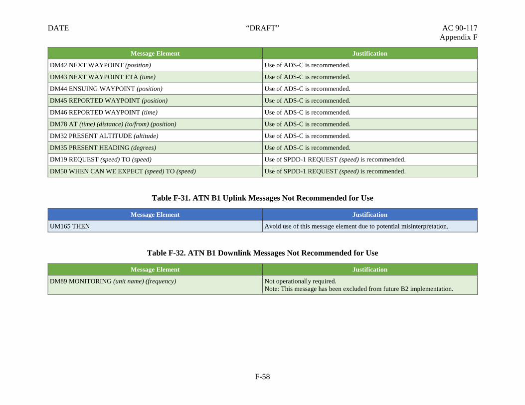
DATE “DRAFT” AC 90-117 Appendix F
Message Element Justification
DM42 NEXT WAYPOINT (position) Use of ADS-C is recommended.
DM43 NEXT WAYPOINT ETA (time) Use of ADS-C is recommended.
DM44 ENSUING WAYPOINT (position) Use of ADS-C is recommended.
DM45 REPORTED WAYPOINT (position) Use of ADS-C is recommended.
DM46 REPORTED WAYPOINT (time) Use of ADS-C is recommended.
DM78 AT (time) (distance) (to/from) (position) Use of ADS-C is recommended.
DM32 PRESENT ALTITUDE (altitude) Use of ADS-C is recommended.
DM35 PRESENT HEADING (degrees) Use of ADS-C is recommended.
DM19 REQUEST (speed) TO (speed) Use of SPDD-1 REQUEST (speed) is recommended.
DM50 WHEN CAN WE EXPECT (speed) TO (speed) Use of SPDD-1 REQUEST (speed) is recommended.
Table F-31. ATN B1 Uplink Messages Not Recommended for Use
Message Element Justification
UM165 THEN Avoid use of this message element due to potential misinterpretation.
Table F-32. ATN B1 Downlink Messages Not Recommended for Use
Message Element Justification
DM89 MONITORING (unit name) (frequency) Not operationally required. Note: This message has been excluded from future B2 implementation.
F-58

DATE “DRAFT” AC 90-117 Appendix G
APPENDIX G. TERMINOLOGY AND ACRONYMS
G.1 Terminology.
1. Aeronautical Telecommunications Network (ATN). A global internetworkarchitecture that allows ground, air-ground, and avionic data subnetworks toexchange digital data for the safety of air navigation and for the regular,efficient, and economic operation of Air Traffic Services (ATS).
2. Air Navigation Services Provider (ANSP). An organization responsible forthe provision of ATS.
3. Air Traffic Data Link Service. A data communication capability comprisingair/ground and ground/ground data network services, specified data linkmessage sets and protocols, aircraft equipment, Air Traffic Service Unit(ATSU) facility equipment, and operational procedures intended to provideprimary or supplemental ATSU communications.
4. Air Traffic Service Unit (ATSU). This domain includes the controller andthe ATSU system which consists of an end system where datacommunications applications reside, a ground to ground router, a ground toground communication network, and human-machine interface (HMI).
5. Aircraft Communications Addressing and Reporting System (ACARS).ACARS is a digital datalink system for transmission of short messagesbetween aircraft and ground stations via airband radio or satellite. ACARS asa term refers to the complete air and ground system, consisting of a serviceprovider and aircraft/ground equipment.
6. Allocations. For approval, design, and monitoring purposes, performancerequirements are provided against allocated human and technical Air TrafficSystem Management (ATM)/Communication, Navigation, and Surveillance(CNS) elements (i.e., the aircraft system, aircraft operator, ANSP, andCommunication Service Provider (CSP)) of the data communicationstransaction.
7. Automatic Dependent Surveillance-Contract (ADS-C). ADS-C is asurveillance information system using automated reports. An agreement isestablished between the ground system and the aircraft via a data link.Without pilot input, the ATSU can establish a “contract” to provide reports ofaircraft position, altitude, speed, elements of navigational intent, andmeteorological data. The system can generate the following types of reports:
• Demand: An ATSU can request an update as needed, and this does not affectan existing contact preset rate.
• Event: A change in vertical rate, lateral deviation, or altitude automaticallytriggers a report.
• Periodic: The ATSU can set or alter the update rate as needed (a higher updaterate is usually required in high traffic areas or with reduced lateral separations).
G-1

DATE “DRAFT” AC 90-117 Appendix G
8. Availability. The probability that an operational communication transactioncan be initiated when needed.
9. Certificate-Holding District Office (CHDO). CHDO is a Flight StandardsService (AFS) office responsible for the administration of 14 CFR part 119certificate authority for operations conducted under 14 CFR parts 121, 125,or 135 for a particular certificate holder.
10. Communication Transaction Time. The maximum time for the completionof the operational communication transaction, after which the initiator shouldrevert to an alternative procedure.
11. Continuity. The probability that an operational communication transactioncan be completed within the communication transaction time.
12. Controller-Pilot Data Link Communications (CPDLC). CPDLC is atwo-way data-link communication system by which controllers can transmitdigital text messages to an aircraft as an alternative to voice communications.Messages from an aircraft to the ATSU may follow a standard format or maybe free text. Messages from a controller normally follow a standard formatand usually require a response from the flightcrew.
13. Current Data Authority (CDA). The designated ground system throughwhich a CPDLC dialogue between a pilot and a controller currentlyresponsible for the flight is permitted to take place.
14. Data Link Communication System. A data link communication system is ameans of transmitting and receiving digital information. “Data link” is ageneric term that encompasses different types of data link communicationsystems and subnetworks. The current systems in use are the ATN Baseline 1(ATN B1), a digital system, and Future Air Navigation System (FANS) 1/A,an analog-based system.
15. Departure Clearance (DCL). DCL (CPDLC-DCL) is the initial phase ofU.S. domestic airspace implementation of data communication and is limitedto tower services. CPDLC-DCL provides automated assistance for requestingand delivering initial and revised DCLs using CPDLC. The DCL includesflight plan route, climb via and/or initial/requested altitude, beacon codeassignment, and departure frequency.
16. Downlink Message (DM). A CPDLC message sent from an aircraft.
17. Flight Standards District Office (FSDO). An FAA field office serving anassigned geographical area and staffed with AFS personnel who serve theaviation industry and the general public on matters relating to the licensing ofaviation personnel, certification of aircraft, operational authorization ofair carriers, and commuter and General Aviation (GA) operations.
18. Future Air Navigation System (FANS). FANS is an avionics system whichprovides direct data link communication between the pilot and the air trafficcontroller. The communications include air traffic control (ATC) clearances,pilot requests and Position Reporting (PR).
G-2

DATE “DRAFT” AC 90-117 Appendix G
19. Integrity. The probability of one or more undetected errors in a completedcommunication transaction.
20. Maximum Accumulated Unplanned Outage Time. A value that defines theacceptable accumulated duration of unplanned outages that exceed theunplanned outage duration limit in a specified time period.
Note: Unplanned outages that are less than the unplanned outage duration limit are considered against the criterion for continuity.
21. Maximum Number of Unplanned Outages. A value that defines theacceptable number of unplanned outages that exceed the unplanned outageduration limit in a specified time period.
Note: Unplanned outages that are less than the unplanned outage duration limit are considered against the criterion for continuity.
22. Minimum Equipment List (MEL). A list which provides for the operationof aircraft, subject to specified conditions, with particular equipmentinoperative, prepared by an operator in conformity with, or more restrictivethan, the Master Minimum Equipment List (MMEL) established for theaircraft type.
23. Next Data Authority (NDA). The ground system so designated by the CDAthrough which an onward transfer of communications and control cantake place.
24. Performance-Based Communication and Surveillance (PBCS). PBCS is aconcept that applies required communication performance (RCP) and requiredsurveillance performance (RSP) specifications to ensure appropriateperformance levels for relevant ATM operations (e.g., application of areduced separation minimum).
25. Pre-Departure Clearance (PDC). A PDC is a clearance that is issued in atext format rather than being issued audibly over a clearance deliveryfrequency. This text clearance is issued through the use of a data linkcommunication computer system and is relayed from a dispatch system to theflightcrew via an ACARS message or a terminal gate printer.
26. Required Communication Performance (RCP). A set of requirements forATS provision, aircraft capability, and operations needed to supportperformance-based communication within a defined airspace.
• RCP Availability - Aircraft (AAIR). An RCP allocation that specifies therequired probability that the aircraft system is serviceable for the relevantcommunication capability.
• RCP Availability – CSP (ACSP). An RCP allocation that specifies the requiredprobability that the CSP systems are available to provide the required level ofcommunication service, given the ATSU’s system is available.
G-3

DATE “DRAFT” AC 90-117 Appendix G
27. Required Surveillance Performance (RSP). A statement of the performancerequirements for operational surveillance in support of specific ATMfunctions.
28. Satellite Voice (SATVOICE). SATVOICE is a long-range communicationsystem (LRCS) that uses a satellite relay, data link communication, highfrequency (HF), or another approved communication systems which extendsbeyond line of sight.
29. Secondary Surveillance Radar (SSR). A type of radar used by ATSU totransmit and receive data on transponder equipped aircraft. This data includesbarometric altitude and identification codes.
30. Supplemental Type Certificate (STC). An STC is a type certificate (TC)issued when an applicant has received FAA approval to modify anaeronautical product from its original design.
31. Surveillance Transaction Time. The surveillance transaction time specifiesthe maximum time for the completion of the operational surveillance process.This parameter is an indication of time criticality.
32. Type Certificate (TC). A TC is issued by the FAA when the airworthinessof an aircraft manufacturing design has been determined to be acceptable.Once issued, the design cannot be changed without approval from the FAA.
33. Uplink Message (UM). A CPDLC message sent from a ground system.
G-4

DATE “DRAFT” AC 90-117 Appendix G
G.2 Acronyms.
Acronym Meaning
4-D Four-Dimensional
4DTRAD Four-Dimensional Trajectory Data Link
14 CFR Title 14 of The Code of Federal Regulations
AC Advisory Circular
ACARS Aircraft Communications Addressing and Reporting System
ACL Air Traffic Control Clearance
ACM Air Traffic Control Communication Management
ACP Actual Communications Performance
ACTP Actual Communication Technical Performance
AD Airworthiness Directive
ADS Automatic Dependent Surveillance
ADS-C Automatic Dependent Surveillance-Contract
AEG Aircraft Evaluation Group
AFM Airplane Flight Manual
AFN Air Traffic Service Facilities Notification
AFS Flight Standards Service
AIP Aeronautical Information Publication
AIS Aeronautical Information Service
AMC Air Traffic Control Microphone Check
ANSP Air Navigation Service Provider
AOC Aeronautical Operational Control
ASP Actual Surveillance Performance
ASTP Actual Surveillance Technical Performance
ATC Air Traffic Control
ATIS Automatic Terminal Information Service
ATM Air Traffic System Management
ATN Aeronautical Telecommunications Network
ATN B1 Aeronautical Telecommunications Network Baseline 1
G-5

DATE “DRAFT” AC 90-117 Appendix G
Acronym Meaning
ATS Air Traffic Service
ATSU Air Traffic Service Unit
B2 Baseline 2
CADS Centralized ADS-C System
CDA Current Data Authority
CDU Control Display Unit
CFR Code of Federal Regulations
CHDO Certificate-Holding District Office
CM Context Management
CNS Communication, Navigation, and Surveillance
CPDLC Controller-Pilot Data Link Communication
CRA Central Reporting Agency
CRD Clearance Request and Delivery
CRM Crew Resource Management
CSP Communication Service Provider
CVR Cockpit Voice Recorder
CWA Central Weather Advisory
D-ATIS Digital Automatic Terminal Information Service
D-TAXI Data Link Taxi
DCL Departure Clearance
DCNS Data Communications Network Service
DLIC Data Link Initiation Capability
DLMA Data Link Monitoring Agency
DM Downlink Message
DRNP Dynamic Required Navigation Performance
DSC Downstream Clearance
DT RSP Data Delivery Time (associated with nominal continuity – 95 percent)
EFB Electronic Flight Bag
EPP Extended Projected Profile
ERAM En Route Automation Modernization
G-6

DATE “DRAFT” AC 90-117 Appendix G
Acronym Meaning
ET Expiration Time
EUROCAE European Organization for Civil Aviation Equipment
FAA Federal Aviation Administration
FANS Future Air Navigation System
FBO Fixed-Base Operator
FDR Flight Data Recorder
FIR Flight Information Region
FLIPCY Flight Plan Consistency
FMS Flight Management System
FOC Flight Operations Center
FSDO Flight Standards District Office
GA General Aviation
GOLD Global Operational Data Link (GOLD) Manual (Doc 10037)
GPS Global Positioning System
HF High Frequency (radio)
HFDL High Frequency Data Link
HMI Human-Machine Interface
ICAO International Civil Aviation Organization
IER Information Exchange and Reporting
IFO International Field Office
IM Interval Management
INMARSAT International Maritime Satellite Organization
INTEROP Interoperability Requirements Standards
ISPACG Informal South Pacific Air Traffic Services Coordinating Group
ITP In-Trail Procedures
LOA Letter of Authorization
LRCS Long-Range Communication System
MEL Minimum Equipment List
METI Meteorological Information
MMEL Master Minimum Equipment List
G-7

DATE “DRAFT” AC 90-117 Appendix G
Acronym Meaning
M/M/S Make, Model, and Series
MOPS Minimum Operational Performance Standard
MSpec Management Specification
MTBO Mean Time Between Outages
MU Management Unit
NAS National Airspace System
NAT North Atlantic
NDA Next Data Authority
NM Nautical Mile
NSDA National Single Data Authority
OCD Oceanic Clearance Delivery
OCL Oceanic Clearance
OEM Original Equipment Manufacturer
OPR Operational Problem Report
OpSpec Operations Specification
OT RSP data overdue time (associated with operational continuity)
PANS Procedures for Air Navigation Service
Part 91K Part 91 Subpart K
PBCS Performance-Based Communication and Surveillance
PBN Performance-Based Navigation
PDC Pre-Departure Clearance
PI Principal Inspector
PIREP Pilot Weather Report
POI Principal Operations Inspector
PORT Pilot Operational Response Time
PR Position Reporting
RA Radar Associate
RCP Required Communication Performance
RCP AAIR RCP Availability – Aircraft
RCP ACSP RCP Availability – CSP
G-8

DATE “DRAFT” AC 90-117 Appendix G
Acronym Meaning
RCP C RCP Continuity
RCP I RCP Integrity
RCTP Required Communication Technical Performance
RF Radio Frequency
RMA Reliability, Maintainability, and Availability
RNAV Area Navigation
RNP Required Navigation Performance
RSMP Required Surveillance Monitored Performance
RSP Required Surveillance Performance
RSP AAIR RSP Availability – Aircraft
RSP ACSP RSP Availability – CSP
RSP C RSP Continuity
RSP I RSP Integrity
RSTP Required Surveillance Technical Performance
RTF Radio Telephone
SARP Standards and Recommended Practices
SATCOM Satellite Communication
SATVOICE Satellite Voice
SBB Swift Broadband
SBD Short Burst Data
SDP Service Delivery Point
SELCAL Selective-Calling Radio System
SID Standard Instrument Departure
SIGMET Significant Meteorological Information
SITA Societe International de Télécommunications Aeronautiques
SOC Statement of Compliance
SPR Safety and Performance Requirements
SSR Secondary Surveillance Radar
STC Supplemental Type Certificate
TC Type Certificate
G-9

DATE “DRAFT” AC 90-117 Appendix G
Acronym Meaning
TDLS Tower Data Link Services
TSO Technical Standard Order
TWIP Terminal Weather Information for Pilots
UM Uplink Message
VDL Very High Frequency Data Link
VHF Very High Frequency (radio)
G-10