Adventure Fortress Playset Instructions - Swing-N-Slide
84
IMPORTANT! THIS MANUAL SUPERSEDES ANY OTHER MANUAL YOU HAVE IN THIS KIT. This Wood Base Kit is used for several other playsets. You may have unused parts after completion of your set.
Transcript of Adventure Fortress Playset Instructions - Swing-N-Slide

IMPORTANT!THIS MANUAL SUPERSEDES ANY
OTHER MANUAL YOU HAVE IN THIS KIT.
This Wood Base Kit is used for several other playsets.
You may have unused parts after completion of your set.

2491-NS
Call Us First!DO NOT RETURN TO STORE.
For immediate help with assembly or product informationcall our toll-free number:
1-866-890-2211April through October M - F 8:00 AM to 6:00 PM EST
Saturday 8:30 AM to 4:30 PM ESTNovember through March M - F 8:00 AM to 5:00 PM EST
or email: [email protected]
Our staff is ready to provide assistance.
STOP!STOP!
- NOTICE -This playset product is not intended for public use. It is intended for
residential application and is not warranted for public or commercial use.
2659-18

(This page intentionally left blank.)

First... Check with your homeowner’s association before assembling. Read instructions thoroughly before you begin. If you
have purchased accessories to accompany this playset, please read all installation instructions beforebeginning assembly of this structure.
Check All Parts If a part is missing, circle the part in question and call.
Important In a drawing, a dotted line represents a part hidden from view (like a part under a panel).
Adult Assistance required Assistance is necessary to handle, fit, and secure some components.Squareness is very Important!Start with a level surface and keep 90° corners and 90° perpendiculars throughout the assembly to ensure all components fit together.
Safety! Check for protruding screws and bolts, verify all screw
and bolt lengths during assembly.
Always wear OSHA-APPROVED safety glasses throughout assembly process.
Tools Required
7/16" Socket1/2" Socket9/16" Socket
Ratchet
Socket Extension
Hammer
9/16" Combination Wrench
#2 Square Drive Bit (included)
Phillips Bit
Combo Drive Bit
Cordless Drill w/Charger
1/8" Drill Bit
7/16" Drill Bit
1/4" Drill Bit
Tape Measure
Level
C - Clamps
8’ Step Ladder
Customer Service1-866-890-22111000 TernesMonroe, MI 4816 Playset
Model:4024, 6013 Backyard Play Systems
Recommended for Ages 3 to 11
- NOTICE -This playset product is not intended for public use. It is intended for
residential application and is not warranted for public or commercial use.
- BEFORE YOU BEGIN -
Your premium playset is manufactured from wood which has many natural characteristics and blemishes that may be present in some of the pieces in your playset. These natural characteristics may include knots or minor cracks/splits. All individual parts have been cut to provide a smooth and safe surface. All parts have been inspected to assure we pack only the safest, most durable wood product. Any minor blemishes in
your playset will not affect the strength, durability, or structural integrity of the finished product. Our limited warranty does not cover the imperfections not resulting in structural failure.
05/10/20182659-18

2
(This page intentionally left blank.)

3
ASSEMBLY SAFETY and HELPFUL HINTS
Wear safety glasses during drilling, assembly of your playset.
Children should not be allowed in the playset assembly and build area.
Note the hole orientation on parts to avoid having to take parts apart later.
Some steps require the assistance of two people to ensure proper assembly, safety during assembly, as well as preventing any damage to the playset.
All hex bolts and lag bolts require a lock washer or lock nut.
To properly install lock nuts, two to three threads must protrude past the lock nut and be exposed once tightened.
Due to wood characteristics and the manufacturing process hex bolts may protrude past a surface. If this condition occurs add additional supplied washers to eliminate bolt protrusion.
To aid in proper assembly pound T-nuts into their respective hole prior to assembly
Pound in T-nuts while the part is on the ground to ensure proper seating.
Use a soft material under parts when pounding in T-nuts to ensure no scratching or de-facing of parts.
Make sure all fasteners used are as specified. Using a fastener not specified in a particular application may result in too much thread exposure or not enough thread engagement.
ASSEMBLY SAFETY and HELPFUL HINTS
STOP!!! Check all parts and hardware before beginning. If any parts aremissing or damaged please circle and call the phone number listed.
DO NOT CONTACT THE STORE OR RETURN YOUR PLAYSET !
KEEP THIS INSTALLATION MANUAL FOR FUTURE CAREAND MAINTENANCE REFERENCE.
To aid in making your playset assembly easier, here is a listing of some helpful hints.
*IMPORTANT HARDWARE INFORMATION*

4
SAFETY WARNINGS
This playset has been designed for use by a maximum of ten occupants at one time having a combined weight of 1,500 pounds. (This weight does not include occupants on the optional monkey bars, glider, or tire swing). This playset is recommended for children (3) through (11) years of age.
On-site adult supervision for children of all ages is recommended.
Instruct children not to walk close to, in front of, behind, or between moving items.
Instruct children not to twist swing chains or ropes or loop them over the top support bar since this may reduce the strength of the chain or rope.
Instruct children to avoid swinging empty seats.
Teach children to sit in the center of the swings with their full weight on the seats.
Instruct children not to use the equipment in a manner other than intended.
Instruct children not to get off equipment while it is in motion.
Parents should dress children appropriately (examples would include the use of well-fitting shoes and the avoidance of ponchos, scarves, and other loose-fitting clothing that is potentially hazardous while using equipment).
Instruct children not to climb when the equipment is wet. Slippery surfaces may cause a hazard.
Verify that suspended climbing ropes, chain, or cable are secured at both ends.
Verify that suspended climbing ropes, chain, or cable cannot be looped back on itself.
Instruct children not to attach items to the playground equipment that are not specifically designed for use with the equipment, such as, but not limited to, jump ropes, clothesline, pet leashes, cables and chain as they may cause a strangulation hazard.
Instruct children to remove their bike or other sports helmet before playing on the playground equipment.
Instruct children to not walk or run up slides.
Instruct children to not pick up slides or ramps as this may cause damage or breakage.
Place the equipment on level ground not less than six (6) feet from any obstructions. Be sure to look overhead for any obstructions above the playset.
Do not use the equipment until fully erected per this playset instruction manual, bolts tightened and the playset is anchored to the ground.
Please read carefully. Observing the following statements and warningsreduces the likelihood of serious or fatal injury.
NOTICE:This playset product is not intended for public use. It is intended for residential application
and is not warranted for public or commercial use.
5
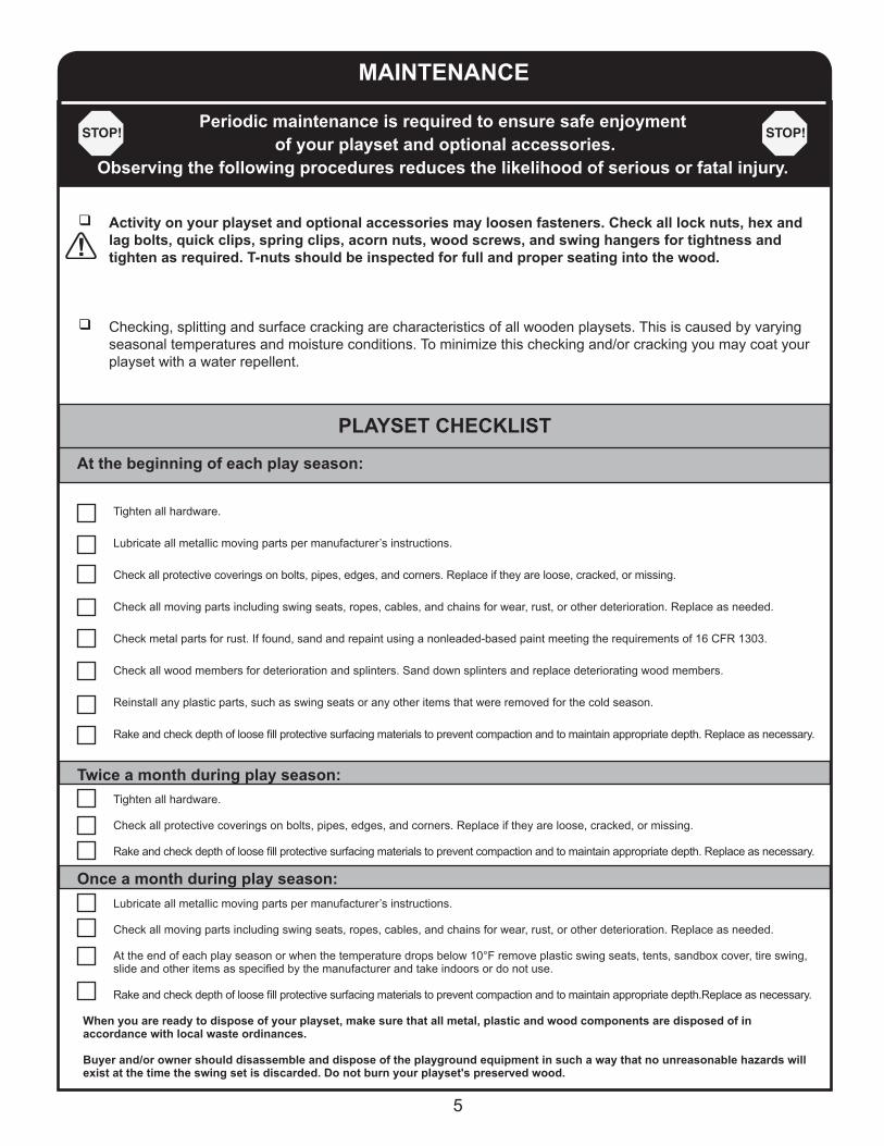
MAINTENANCE
Activity on your playset and optional accessories may loosen fasteners. Check all lock nuts, hex and lag bolts, quick clips, spring clips, acorn nuts, wood screws, and swing hangers for tightness and tighten as required. T-nuts should be inspected for full and proper seating into the wood.
Checking, splitting and surface cracking are characteristics of all wooden playsets. This is caused by varying seasonal temperatures and moisture conditions. To minimize this checking and/or cracking you may coat your playset with a water repellent.
Tighten all hardware.
Lubricate all metallic moving parts per manufacturer’s instructions.
Check all protective coverings on bolts, pipes, edges, and corners. Replace if they are loose, cracked, or missing. Check all moving parts including swing seats, ropes, cables, and chains for wear, rust, or other deterioration. Replace as needed.
Check metal parts for rust. If found, sand and repaint using a nonleaded-based paint meeting the requirements of 16 CFR 1303.
Check all wood members for deterioration and splinters. Sand down splinters and replace deteriorating wood members.
Reinstall any plastic parts, such as swing seats or any other items that were removed for the cold season.
Rake and check depth of loose fill protective surfacing materials to prevent compaction and to maintain appropriate depth. Replace as necessary. Tighten all hardware. Check all protective coverings on bolts, pipes, edges, and corners. Replace if they are loose, cracked, or missing. Rake and check depth of loose fill protective surfacing materials to prevent compaction and to maintain appropriate depth. Replace as necessary. Lubricate all metallic moving parts per manufacturer’s instructions. Check all moving parts including swing seats, ropes, cables, and chains for wear, rust, or other deterioration. Replace as needed. At the end of each play season or when the temperature drops below 10°F remove plastic swing seats, tents, sandbox cover, tire swing, slide and other items as specified by the manufacturer and take indoors or do not use. Rake and check depth of loose fill protective surfacing materials to prevent compaction and to maintain appropriate depth.Replace as necessary. When you are ready to dispose of your playset, make sure that all metal, plastic and wood components are disposed of in accordance with local waste ordinances. Buyer and/or owner should disassemble and dispose of the playground equipment in such a way that no unreasonable hazards will exist at the time the swing set is discarded. Do not burn your playset's preserved wood.
Periodic maintenance is required to ensure safe enjoyment of your playset and optional accessories.
Observing the following procedures reduces the likelihood of serious or fatal injury.
PLAYSET CHECKLIST
At the beginning of each play season:
Twice a month during play season:
Once a month during play season:

6
PLAYGROUND SURFACING MATERIALSSECTION 4 OF THE CONSUMER PRODUCT SAFETY COMMISSION’S OUTDOOR HOME PLAYGROUND SAFETY HANDBOOK9
Select Protective SurfacingOne of the most important things you can do to reduce the likelihood of serious head injuries is to install shock-absorbing protective surfacing under and around your play equipment. The protective surfacing should be applied to a depth that is suitable for the equipment height in accordance with ASTM Specification F 1292. There are different types of surfacing to choose from; whichever product you select, follow these guidelines: NOTE: Do not install home playground equipment over concrete, asphalt, or any other hard surface. A fall onto a hard surface can result in serious injury to the equipment user. Grass and dirt are not considered protective surfacing because wear and environmental factors can reduce their shock absorbing effectiveness. Carpeting and thin mats are generally not adequate protective surfacing. Ground level equipment – such as a sandbox, activity wall, playhouse or other equipment that has no elevated play surface – does not need any protective surfacing.
Maximum fall height for this playset is 82”. Loose-Fill Materials: Maintain a minimum depth of 9 inches of loose- fill materials such as wood mulch/chips, engineered wood fiber (EWF), or shredded/recycled rubber mulch for equipment up to 8 feet high; and 9 inches of sand or pea gravel for equipment up to 5 feet high. NOTE: An initial fill level of 12 inches will compress to about a 9- inch depth of surfacing over time. The surfacing will also compact, displace, and settle, and should be periodically refilled to maintain at least a 9- inch depth. Use a minimum of 6 inches of protective surfacing for play equipment less than 4 feet in height. If maintained properly, this should be adequate. (At depths less than 6 inches, the protective material is too easily displaced or compacted.) Use containment, such as digging out around the perimeter and/or lining the perimeter with landscape edging. Don’t forget to account for water drainage. U.S Consumer Product Safety Commission, Washington, D.C., 20207 or call the toll-free hotline :1-800-638-2772 Check and maintain the depth of the loose-fill surfacing material. To maintain the right amount of loose-fill materials, mark the correct level on play equipment support posts. That way you can easily see when to replenish and/or redistribute the surfacing. Do not install loose fill surfacing over hard surfaces such as concrete or asphalt.
Poured-In-Place Surfaces or Pre-Manufactured Rubber Tiles:You may be interested in using surfacing other than loose-fill materials – like rubber tiles or poured-in-place surfaces. Installations of these surfaces generally require a professional and are not “do-it-yourself” projects. Review surface specifications before purchasing this type of surfacing. Ask the installer/manufacturer for a report showing that the product has been tested to the following safety standard: ASTM F 1292 Standard Specification for Impact Attenuation of Surfacing Materials within the Use Zone of Playground Equipment. This report should show the specific height for which the surface is intended to protect against serious head injury. This height should be equal to or greater than the fall height – vertical distance between a designated play surface (elevated surface for standing, sitting, or climbing) and the protective surfacing below – of your play equipment. Check the protective surfacing frequently for wear.
PlacementProper placement and maintenance of protective surfacing is essential. Be sure to Extend surfacing at least 6 feet from the equipment in all directions. For to-fro swings, extend protective surfacing in front of and behind the swing to a distance equal to twice the height of the top bar from which the swing is suspended. For tire swings, extend surfacing in a circle whose radius is equal to the height of the suspending chain or rope, plus 6 feet in all directions.
2H 2H
H
L
6 ft.6 ft.
6 ft. 6 ft.
L+6 ft.
6 ft.6 ft.
Use Zone for Single-Axis Swings Use Zone for Multi-Axis Swings
Denotes Use Zone with Protective Surfacing
Denotes Use Zone with Protective Surfacing
9 This information has been extracted from the CPSC publications “Playground Surfacing—Technical Information Guide” and “Handbook for Public Playground Safety.” Copies of these reports can be obtained by sending a postcard to the: Office of Public Affairs, U.S. Consumer Product Safety Commission, Washington, D.C., 20207 or call the toll-free hotline: 1-800-638-2772
7
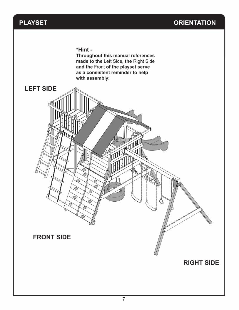
PLAYSET ORIENTATION
*Hint -Throughout this manual references made to the Left Side, the Right Side and the Front of the playset serve as a consistent reminder to help with assembly:
RIGHT SIDE
FRONT SIDE
LEFT SIDE
8
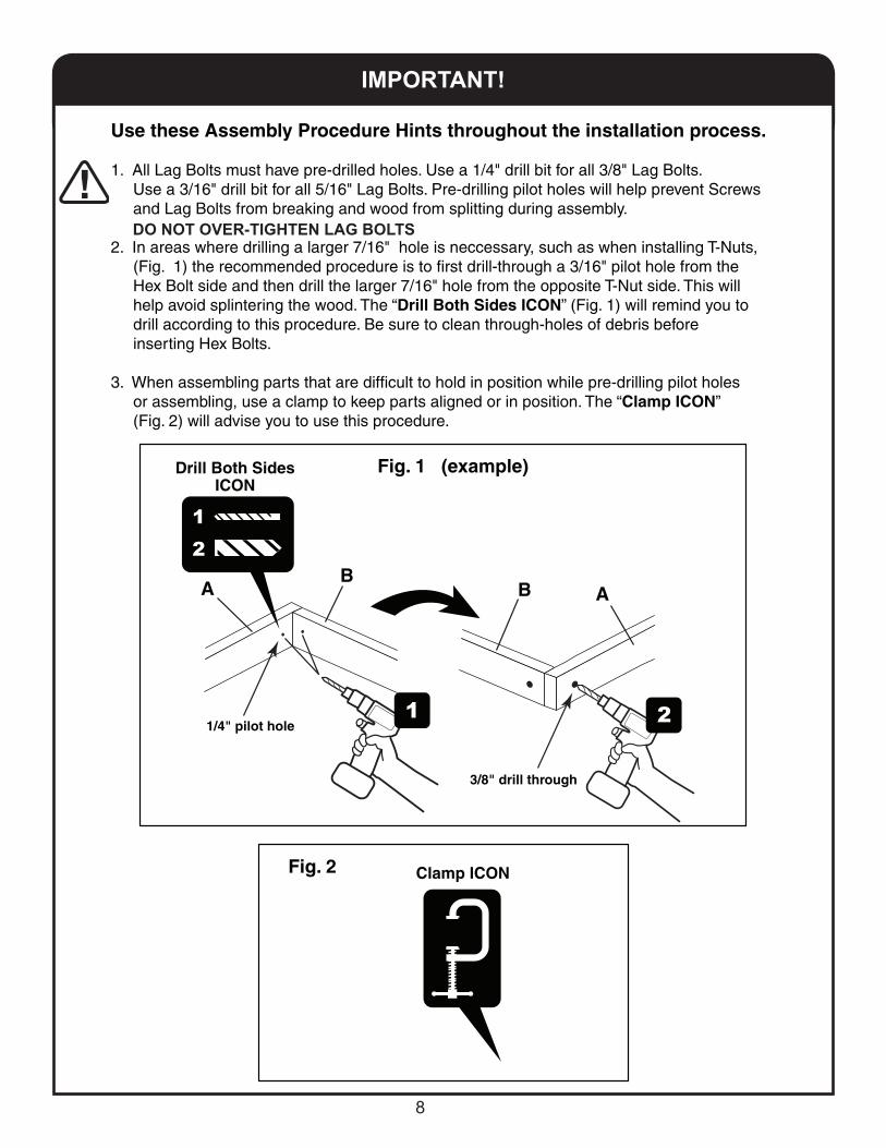
IMPORTANT!
A A B B
Use these Assembly Procedure Hints throughout the installation process.
1. All Lag Bolts must have pre-drilled holes. Use a 1/4" drill bit for all 3/8" Lag Bolts. Use a 3/16" drill bit for all 5/16" Lag Bolts. Pre-drilling pilot holes will help prevent Screws and Lag Bolts from breaking and wood from splitting during assembly.
2. In areas where drilling a larger 7/16" hole is neccessary, such as when installing T-Nuts, (Fig. 1) the recommended procedure is to first drill-through a 3/16" pilot hole from the Hex Bolt side and then drill the larger 7/16" hole from the opposite T-Nut side. This will help avoid splintering the wood. The “Drill Both Sides ICON” (Fig. 1) will remind you to drill according to this procedure. Be sure to clean through-holes of debris before inserting Hex Bolts.
3. When assembling parts that are difficult to hold in position while pre-drilling pilot holes or assembling, use a clamp to keep parts aligned or in position. The “Clamp ICON” (Fig. 2) will advise you to use this procedure.
Fig. 1 (example)
Fig. 2
Drill Both Sides ICON
Clamp ICON
1/4" pilot hole
3/8" drill through
DO NOT OVER-TIGHTEN LAG BOLTS
9
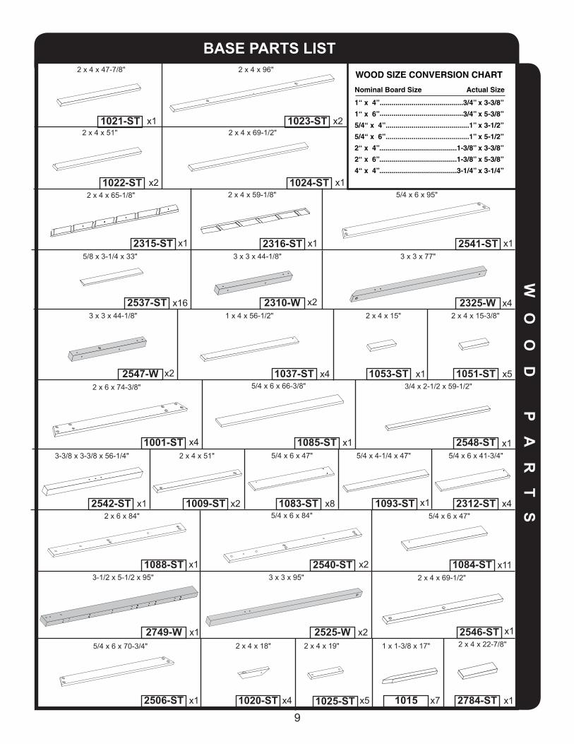
BASE PARTS LISTW
OO
D
PA
RT
S
x4
x2x1
x1
x1
5/4 x 6 x 66-3/8"
1001-ST
1083-ST
1088-ST
2749-W
2506-ST 1020-ST
2312-ST
2548-ST
2546-ST
1084-ST
10151025-ST
1009-ST2542-ST 1093-ST
1085-ST
1024-ST
1023-ST
1022-ST
1021-ST
1051-ST
2784-ST
1053-ST
x5 x7
WOOD SIZE CONVERSION CHART
Nominal Board Size Actual Size
1“ x 4”..........................................3/4” x 3-3/8”
1“ x 6” 3/4” x 5-3/8”
5/4“ x 4”..........................................1” x 3-1/2”
5/4“ x 6”..........................................1” x 5-1/2”
2“ x 4”.......................................1-3/8” x 3-3/8”
2“ x 6”.......................................1-3/8” x 5-3/8”
4“ x 4”.......................................3-1/4” x 3-1/4”
..........................................
x1
2 x 6 x 74-3/8"
2315-ST x1
x5
x1
x1
2 x 4 x 59-1/8" 5/4 x 6 x 95"
2 x 4 x 15" 2 x 4 x 15-3/8"
2 x 4 x 22-7/8"
2 x 4 x 51"3-3/8 x 3-3/8 x 56-1/4"
3/4 x 2-1/2 x 59-1/2"
2 x 4 x 69-1/2"3 x 3 x 95"
5/4 x 6 x 70-3/4"
x4
2 x 4 x 19"2 x 4 x 18"
x41037-ST
1 x 4 x 56-1/2"2537-ST x16
3 x 3 x 77"
x42325-W
3 x 3 x 44-1/8"
x22310-W
x8
5/4 x 6 x 47"
5/8 x 3-1/4 x 33"
x1
x1 x4
x1
x1
5/4 x 4-1/4 x 47" 5/4 x 6 x 41-3/4"
x11
5/4 x 6 x 47"
x1
1 x 1-3/8 x 17"
3-1/2 x 5-1/2 x 95"
2 x 4 x 65-1/8"
2 x 6 x 84"
2 x 4 x 69-1/2"2 x 4 x 51"x2
2 x 4 x 47-7/8"
x1
x2
2 x 4 x 96"
2525-W x2
x22547-W
3 x 3 x 44-1/8"
x1 x12316-ST 2541-ST
5/4 x 6 x 84"
x22540-ST

10
BA
SE
A
CC
ES
SO
RI
ES
x1
x1
x1
x1 x1
90o Angle Bracket Plate
BA
SE
H
AR
DW
AR
E
Swing Beam Flat Plate
Quick ClipSwing Hanger
Plaque
x6
x1
x6Safety Handle
x3
x6
x6
Rope Slide Slide
Tent Tarp Climbing Rocks - Green
Climbing Rocks - Yellow
Swing Beam Angled Plate Left
Swing Beam Angled Plate Right
Swing Beam 90o Plate
x4
Plastic Hole-PlugAngled
x4
Angle plug
2167 WS4542
WS4541
2411
2448
2447
2485 2449
WS4889
Sling Swing
x2WS4885SA3098
x2WS4410Trapeze Bar
x1WS1501
x12641
x1
Telescope
Steering Wheel
x1
WS4610
WS4412
x1Green
SP3029 x1Yellow
SP3030

11
SWING BEAM A - FRAME
T-Nut x2
x23 x 3 x 95"
2525-W
Rotate 2525-W 180o after installing T-Nuts.
HARDWARE BAGS NEEDED:17044
IMPORTANT!
Please arrange HARDWARE BAGSin numerical order.
Arranging the hardware bags will be helpful during assembly.
The numbered hardware bags will be referenced throughout this
instruction manual.
EXAMPLE:

12
3"
x8
1" 1"
3/8" T - NUT
3/8" FLAT WASHER
1/4" x 1" FENDER WASHER 3/16" x 1” FENDER WASHER
3/8" LOCK WASHER
TRUSS HEAD SCREW
3/4"
3/8” LAG BOLT WOODSCREWS
3/8" LOCK NUT
4"
3/8"
2-1/2"
3"
1-1/4"2"
2-1/2"PAN HEAD SCREW
2-1/2"
1-5/8" 1-3/4"
x26
x13
x6 x13
x67
x45
x4
x70 x58 x8 x50x150x5
x6
x6
x89
x12
1/4” ROCK WALL HARDWARE
T - Nut
LockWasher
Hex Bolt
2452 (2) BAGS
FlatWasher1-1/2"
1/4" SAFETY HANDLE HDW.
LagScrew
FlatWasher
1-1/2"
A C T U A L S I Z E S H O W N
STAR DRIVE BIT
x1

13
5-1/4"4-1/2"
3/8"
4"
3/8"
3-3/4”
3/8"
3/8"
2"
3/8"
1-1/2"
3/8"
1-1/4"
3/8"
2-1/2"
3/8"
5-1/2"
3/8"
x4x16
x1
x1x14
x2
x2 x1 x1
A C T U A L S I Z E S H O W N

14
3/8"
3/8"
3/8"
3/8"
3/8"
3/8"
3/8"
3/8" TORQUEWASHER
3/8"
3-1/2"
3-3/4" 4-1/2" 6-1/2"6"
7"
9"
x2
x6 x2 x2x2 x12 x1
A C T U A L S I Z E S H O W N
x16

15
WO
OD
P
A
R
T S
TOWER & BRIDGE PARTS LIST
x2x7
x4
x1
x4
WOOD SIZE CONVERSION CHART
Nominal Board Size Actual Size
1“ x 4”..........................................3/4” x 3-3/8”
1“ x 6” 3/4” x 5-3/8”
5/4“ x 4”..........................................1” x 3-1/2”
5/4“ x 6”..........................................1” x 5-1/2”
2“ x 4”.......................................1-3/8” x 3-3/8”
2“ x 6”.......................................1-3/8” x 5-3/8”
4“ x 4”.......................................3-1/4” x 3-1/4”
..........................................
x1
x5
x6
2 x 4 x 34-7/8"
2 x 4 x 15-3/8"
x25
5/4 x 6 x 46-3/8"
5/8 x 3-1/4 x 33"
2 x 4 x 25-1/4"
x1 x1 x2
5/4 x 6 x 23-1/2" 5/4 x 4-1/2 x 39"
5/4 x 6 x 47"
x1
x4
x2
2 x 4 x 46-3/4"
2 x 4 x 43-1/2"
x1
2 x 4 x 46-3/4"
x2
x4
5/4 x 5-3/8 x 22-1/2"
2 x 4 x 18"
x5
Metal Handrail
x1
x1
9" Hand Grip
2 x 4 x 38-5/8"
x12 x 4 x 85-3/8"
x1
5/4 x 5 x 47"
x2
2327-ST
1096-ST
2329-W
2336-ST
1113-ST
2334-ST
1116-ST
1120-ST
2084
1020-ST
WS4410 2083
1124-ST
1114-ST
x4
1 x 1-3/8 x 17"
1015
1094-ST
1051-ST
2330-ST
2331-ST
1115-ST
1117-ST
1119-W
1121-ST
2326-ST
2537-ST
2 x 4 x 45-3/8" 2 x 4 x 45-3/8"
3 x 3 x 95" 2 x 4 x 64"
2 x 4 x 64"2 x 4 x 84"
2 x 4 x 37-1/4"
x11118-ST
5/4 x 4 x 25-5/8"
2222-ST x1
5/4 x 4 x 17"
x12313-ST
Round-Hole
90o Angle Bracket
x12335-ST
HD
W.
16
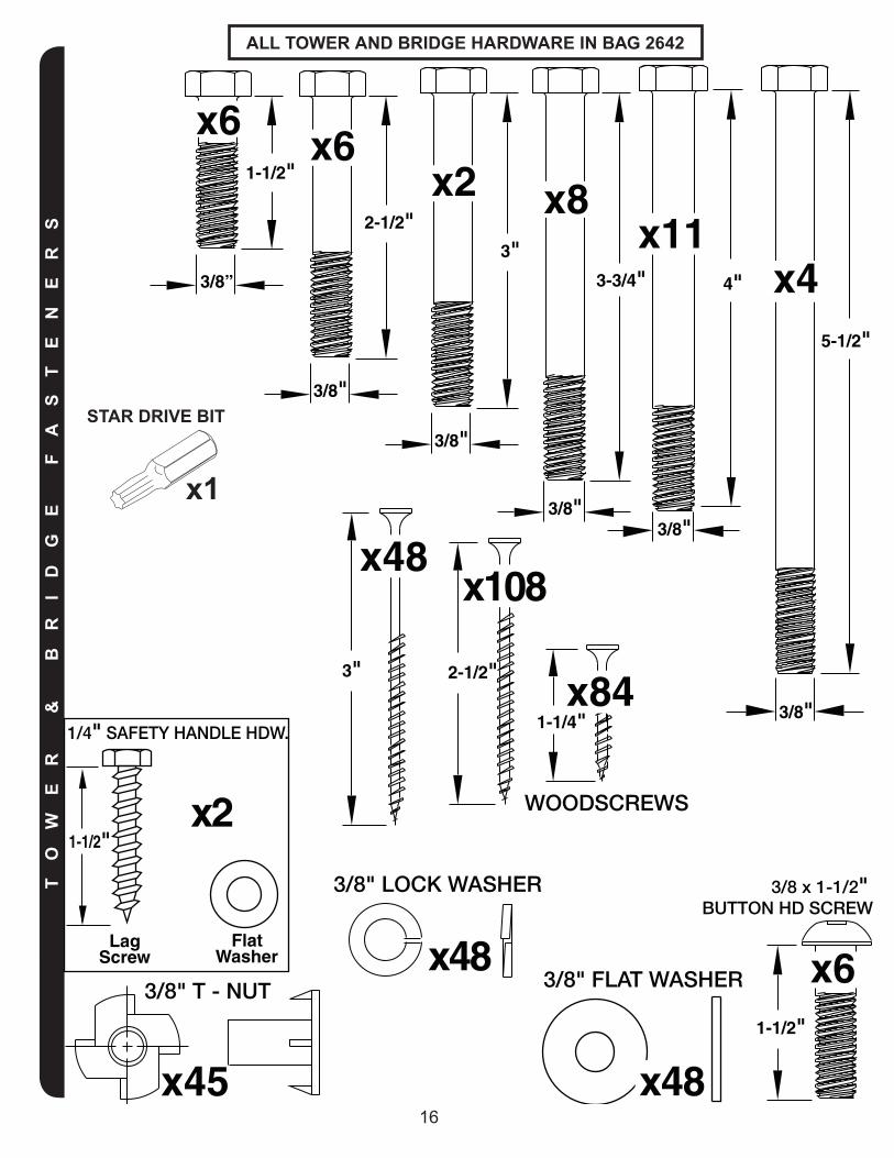
1-1/2"
x6
3/8 x 1-1/2" BUTTON HD SCREW
3/8" T - NUT 3/8" FLAT WASHER
3/8" LOCK WASHER
1/4" SAFETY HANDLE HDW.
Lag Screw
Flat Washer
1-1/2"
3/8" HEX HEAD BOLTS
4"
3/8"
2-1/2"
3/8"
3"
3/8"
5-1/2"
3/8"
x4
x61-1/2"
3/8”
x6
x2
3-3/4"
3/8"
x8x11
#2 SQUARE DRIVE BIT
x1
x48
x45
x2
x48
WOODSCREWS
2-1/2"3"
1-1/4"x84
x48x108
TO
WE
R
&
BR
ID
GE
F
AS
TE
NE
RS
ALL TOWER AND BRIDGE HARDWARE IN BAG 2642
STAR DRIVE BIT
x1

17
29'-5"17'-5"
6' SAFETY AREA
6' SAFETY AREA
19'-10"
31'-10"
11'-1"HEIGHT
SET-UP
SWING
ROCK WALL
TOWER
LEFT SIDE RIGHT SIDE
FRONT SIDE
BACK SIDE
SLIDES
ORIENTATION
This space intentionally left blank.
18
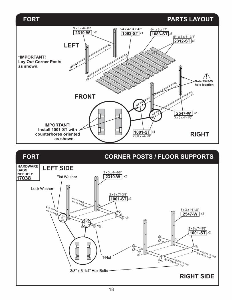
FORT PARTS LAYOUT
RIGHT
FRONT
*IMPORTANT! Lay Out Corner Postsas shown.
IMPORTANT! Install 1001-ST with
counterbores oriented as shown.
FORT CORNER POSTS / FLOOR SUPPORTS
3/8” x 5-1/4” Hex Bolts
T-Nut
Flat Washer
Lock Washer
LEFT SIDE
RIGHT SIDE
LEFT
x85/4 x 6 x 47"1083-ST
x45/4 x 6 x 41-3/4"2312-ST
x15/4 x 4-1/4 x 47"1093-ST x2
3 x 3 x 44-1/8"2310-W
x23 x 3 x 44-1/8"2547-W
x42 x 6 x 74-3/8"1001-ST
x22 x 6 x 74-3/8"1001-ST
x22 x 6 x 74-3/8"1001-ST
x23 x 3 x 44-1/8"2310-W
x23 x 3 x 44-1/8"2547-W
Note 2547-W hole location.
HARDWARE BAGS NEEDED:17038

19
FORT CORNER POSTS / FLOOR
2-1/2" Wood Screws x52
Board will ovehang.
Flush
48"Outside of Posts
Outside of Posts 48"
56-1/2" 56-1/2"
x85/4 x 6 x 47"1083-ST
x41 x 6 x 41-3/4"2312-ST
x15/4 x 4-1/4 x 47"1093-ST
FORT CORNER POSTS / FLOOR
T-Nut x14
Pre-fit deck boards so they are evenly spaced
before installing screws.
Center boards between48" and corner posts.
Make sure corner posts are squared to measurements shown.
HARDWARE BAGS NEEDED:17034
HARDWARE BAGS NEEDED:17039

20
FORT SIDE WALLS
LEFT SIDE
RIGHT SIDE
Flush at ends.
Sets on 1001-ST
3" Wood Screwsx 16
Keep 56-1/2" measurement when installing 1037-ST
x21 x 4 x 56-1/2"1037-ST
x21 x 4 x 56-1/2"1037-ST
35-1/4"
35-1/4"
35-1/4"
35-1/4"
56-1/2"
4” Hex Bolt
Lock Washer
Flat Washer
4” Hex Bolt
Lock Washer
Flat Washer
FORT TENT SIDE RAILS
LEFT SIDE
RIGHT SIDE
x22 x 4 x 96"1023-ST
Install bolts firmly, but do not fully tighten. Re-adjustment will be neccessary.
HARDWARE BAGS NEEDED:17039
HARDWARE BAGS NEEDED:17035
21
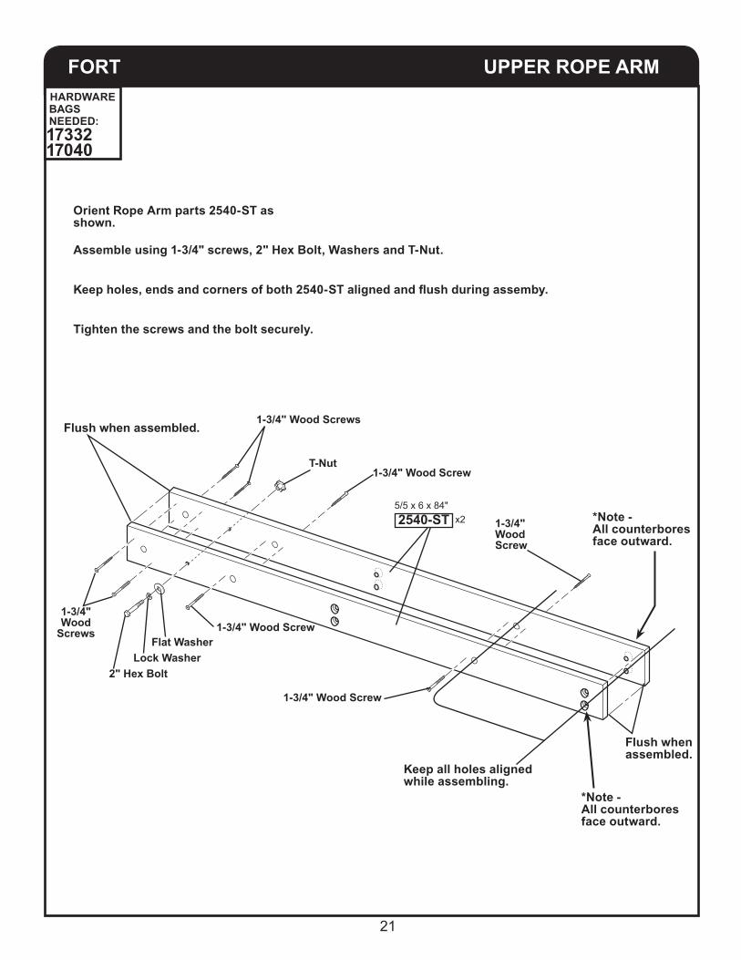
FORT UPPER ROPE ARM
Flush when assembled.
Flush whenassembled.
Orient Rope Arm parts 2540-ST as shown.
Assemble using 1-3/4" screws, 2" Hex Bolt, Washers and T-Nut.
Keep holes, ends and corners of both 2540-ST aligned and flush during assemby.
Keep all holes aligned while assembling.
*Note -All counterbores face outward.
*Note -All counterbores face outward.
Tighten the screws and the bolt securely.
1-3/4" Wood Screws
1-3/4"Wood
Screws
1-3/4" Wood Screw
1-3/4" Wood Screw
1-3/4" Wood Screw
1-3/4" Wood Screw
T-Nut
Flat Washer Lock Washer2" Hex Bolt
x25/5 x 6 x 84"2540-ST
HARDWARE BAGS NEEDED:1733217040

22
48"
56-1/2"
56-1/2"
48"
FORT TENT END RAILS
RIGHT SIDE
LEFT SIDE
Check and keep all measurements while tightening all bolts securely.
5” Hex Bolt
Lock Washer
3-1/2” Lag Bolt
3-1/2” Lag Bolt
Flat Washer
4” Hex Bolt
Lock Washer
Flat Washer
Lock Washer
Flat Washer
FORT UPPER ARMS
x12 x 4 x 51"1009-ST
x1 Pre-Assembled5/4 x 6 x 84"2540-ST
Install bolts firmly, but do not fully tighten. Re-adjustment will be neccessary.
DO NOT OVER-TIGHTEN LAG BOLTS
PRE-DRILL 1/4" x 1-1/2" DEEP before installing lag bolts.
HARDWARE BAGS NEEDED:17040
RIGHT SIDE
LEFT SIDE
3" Lag Bolt
3" Lag Bolt
23
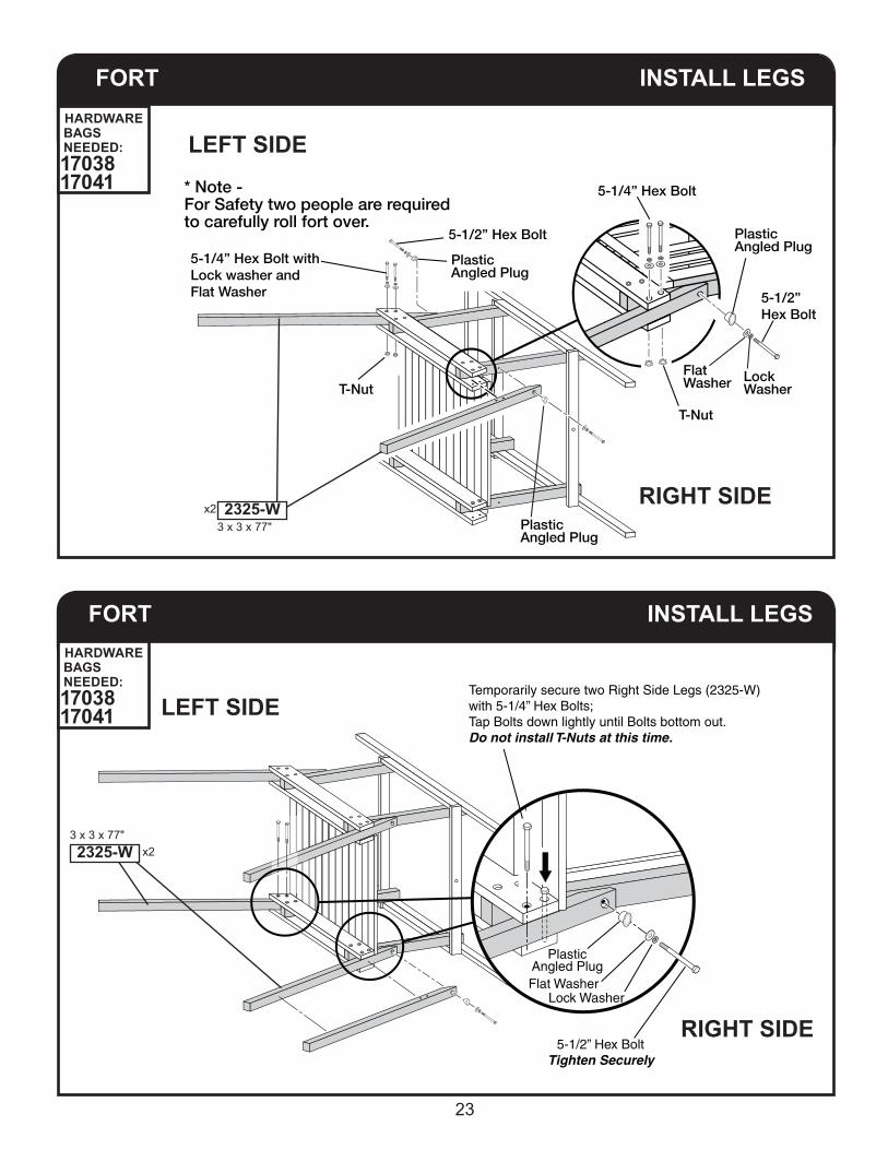
Temporarily secure two Right Side Legs (2325-W)with 5-1/4” Hex Bolts;Tap Bolts down lightly until Bolts bottom out.Do not install T-Nuts at this time.
Lock Washer Flat Washer
Plastic Angled Plug
5-1/2” Hex Bolt Tighten Securely
FORT INSTALL LEGS
FORT INSTALL LEGS
LEFT SIDE
LEFT SIDE
5-1/4” Hex Bolt withLock washer andFlat Washer
T-Nut
5-1/2” Hex Bolt
T-Nut
5-1/4” Hex Bolt
5-1/2” Hex Bolt
Flat Washer Lock
Washer
Plastic Angled Plug
Plastic Angled Plug
Plastic Angled Plug
* Note - For Safety two people are required to carefully roll fort over.
x23 x 3 x 77"2325-W
x23 x 3 x 77"2325-W
RIGHT SIDE
RIGHT SIDE
HARDWARE BAGS NEEDED:1703817041
HARDWARE BAGS NEEDED:1703817041
24
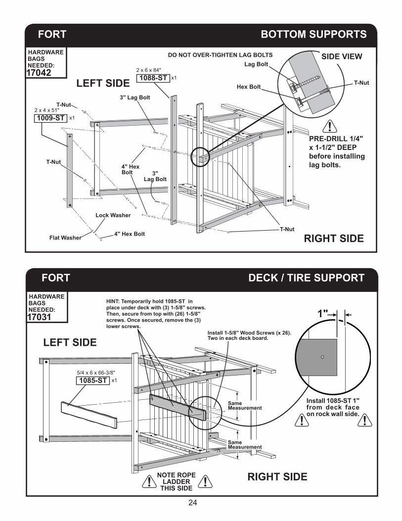
FORT DECK / TIRE SUPPORT
LEFT SIDE
RIGHT SIDE
1"Install 1-5/8" Wood Screws (x 26). Two in each deck board.
Same Measurement
Install 1085-ST 1" from deck face on rock wall side.
NOTE ROPE LADDER
THIS SIDE
Same Measurement
x15/4 x 6 x 66-3/8"1085-ST
HINT: Temporarily hold 1085-ST in place under deck with (3) 1-5/8" screws.Then, secure from top with (26) 1-5/8" screws. Once secured, remove the (3) lower screws.
4" Hex Bolt
T-Nut
T-Nut
T-Nut
Lock Washer
4" HexBolt
Flat Washer
3" Lag Bolt
3"Lag Bolt
FORT BOTTOM SUPPORTS
LEFT SIDE
RIGHT SIDE
SIDE VIEWLag Bolt
Hex Bolt T-Nut x1
2 x 6 x 84"1088-ST
x12 x 4 x 51"1009-ST
DO NOT OVER-TIGHTEN LAG BOLTS
PRE-DRILL 1/4" x 1-1/2" DEEP before installing lag bolts.
HARDWARE BAGS NEEDED:17042
HARDWARE BAGS NEEDED:17031

25
FORT INSTALL LEGS
After tightening all bolts Gently return Playset to it’s upright position. Move partially assembled Playset into it’s permanent location at this time, making sure ground has been leveled and prepared.
Lock Washer
T-Nut
1st position
2nd position
Flat Washer
Remove and re-insert each 5-1/4" Hex Bolt (one at a time) through the holes from the opposite direction - this time using a Lock Washer, Flat Washer and T-Nut Install And Tighten Into T-Nuts At This Time.
* Note - For Safety two people are required to carefully roll fort over.
RIGHT SIDELEFT SIDE
26
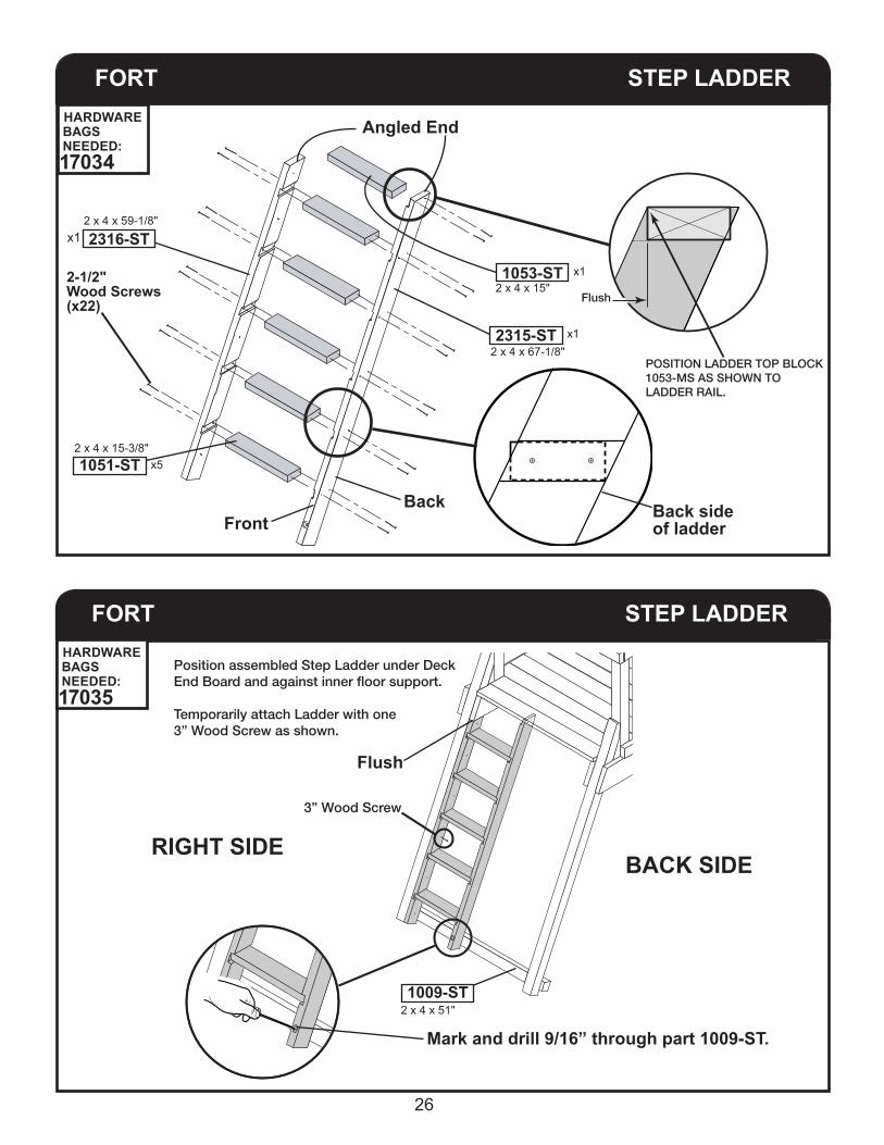
FORT STEP LADDER
Position assembled Step Ladder under DeckEnd Board and against inner floor support.
Temporarily attach Ladder with one3” Wood Screw as shown.
3” Wood Screw
RIGHT SIDEBACK SIDE
Flush
FORT STEP LADDER
Back side of ladder
Mark and drill 9/16” through part 1009-ST.
Angled End
2-1/2" Wood Screws (x22)
BackFront
Flush
POSITION LADDER TOP BLOCK1053-MS AS SHOWN TOLADDER RAIL.
HARDWARE BAGS NEEDED:17035
x52 x 4 x 15-3/8"1051-ST
x12 x 4 x 59-1/8"
2316-ST
x12 x 4 x 15"1053-ST
x12 x 4 x 67-1/8"2315-ST
2 x 4 x 51"1009-ST
HARDWARE BAGS NEEDED:17034

27
FORT STEP LADDER
4-1/2” Hex Bolt
3” WoodScrews
x5
LockWasher
FlatWasher
T-Nut
Flush
Position Ladder Top Blockbeneath Deck End Board.
Attach with three 1-5/8” Wood Screws.
When installed, front edge of LadderTop Block (1053-ST) should be flush with
top of Step Ladder.
1-5/8” Screws (x3)
x12 x 4 x 15"1053-ST
x12 x 4 x 15"
1053-ST
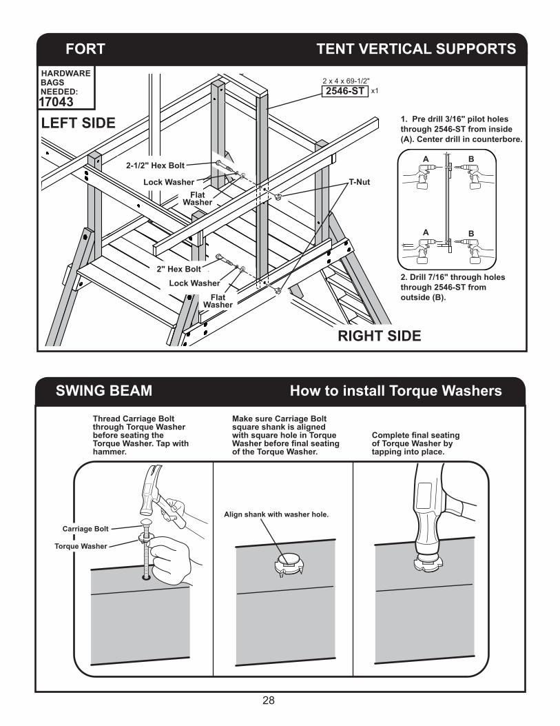
FORT TENT VERTICAL SUPPORTS
*Note: Bottom end of 1024-ST rests on Deck Floor.
*Note: Align 1024-STCentered with Pre-Drilledholes in Tent Side Rail (1023-ST).
RIGHT SIDE
RIGHT SIDE
LEFT SIDE
LEFT SIDE
x12 x 4 x 69-1/2"1024-ST x1
2 x 4 x 69-1/2"2546-ST
IMPORTANT! Install 2546-ST with
counterbores toward inside of fort.
2-1/2" Wood Screwsx2
1-5/8" Wood Screws
x6
1-5/8" Wood Screws
HARDWARE BAGS NEEDED:1704317031 17035
HARDWARE BAGS NEEDED:17031 17034
28
SWING BEAM How to install Torque Washers
Thread Carriage Bolt through Torque Washer before seating the Torque Washer. Tap with hammer.
Complete final seating of Torque Washer by tapping into place.
Make sure Carriage Bolt square shank is aligned with square hole in Torque Washer before final seating of the Torque Washer.
Carriage Bolt
Align shank with washer hole.
Torque Washer
FORT TENT VERTICAL SUPPORTS
RIGHT SIDE
LEFT SIDE
x12 x 4 x 69-1/2"2546-ST
T-Nut
A
A B
B2-1/2" Hex Bolt
Lock Washer
Lock Washer
Flat Washer
Flat Washer
2" Hex Bolt
1. Pre drill 3/16" pilot holes through 2546-ST from inside (A). Center drill in counterbore.
2. Drill 7/16" through holes through 2546-ST from outside (B).
HARDWARE BAGS NEEDED:17043

29
SWING BEAM SWING HANGERS
7" Carriage Boltsx12
Lock Nutx12
Flat Washerx12
Torque Washerx12
7" Carriage Bolt
x12
Lock Nut
Flat Washer
Torque Washer
SWING BEAM SUPPORTSWING BEAM
RIGHT SIDE
LEFT SIDE
x13-3/8 x 3-3/8 x 56-1/4"2542-ST
Lock Nut
Lock Nut
Flat Washer
Tap Carriage Bolt and Torque Washer into place.
Torque Washer
Torque Washer
6" Carriage Bolt
6" Carriage Bolt
Flat Washer
Smaller holes at TOP
3-1/2 x 5-1/2 x 95" x12749-W
x6WS4889NOTE: Ensure two to three threads are exposed past Lock Nut.
NOTE: You may need to tap bolts with hammer to get through holes. Clean all debris from bolt threads before installing lock nuts.
HARDWARE BAGS NEEDED:17044
HARDWARE SUPPLIED WITH HANGER

30
SWING BEAM A - FRAME
T-Nut x2
x23 x 3 x 95"
2525-W
Rotate 2525-W 180o after installing T-Nuts.
SWING BEAM ASSEMBLE
x1
x23-3/4” Hex BoltLock WasherFlat Washer
5/4 x 6 x 70-3/4”2506-STPre-installed T-Nuts
are underneath.
HARDWARE BAGS NEEDED:17044
HARDWARE BAGS NEEDED:17044

31
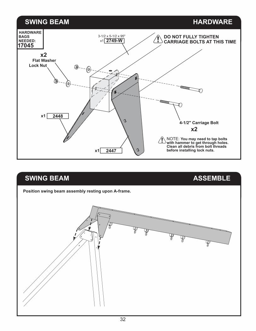
SWING BEAM HARDWARE
Lock NutFlat Washer
x1
3-3/4" Carriage Boltx2
2525-W
2499
DO NOT FULLY TIGHTEN CARRIAGE BOLTS AT THIS TIME
SWING BEAM HARDWARE
Flat Washer Lock Nut
3-1/2" Carriage Bolt x2
x2
2411x1
RIGHT SIDE
BACK SIDE
NOTE: Ensure two to three threads are exposed past Lock Nut.
NOTE: You may need to tap bolts with hammer to get through holes. Clean all debris from bolt threads before installing lock nuts.
HARDWARE BAGS NEEDED:17045
HARDWARE BAGS NEEDED:17045
32
SWING BEAM HARDWARE
x1
x1
x2 Flat WasherLock Nut
2448
2447
4-1/2" Carriage Bolt x2
DO NOT FULLY TIGHTEN CARRIAGE BOLTS AT THIS TIME
3-1/2 x 5-1/2 x 95" x1 2749-W
SWING BEAM ASSEMBLE
Position swing beam assembly resting upon A-frame.
NOTE: You may need to tap bolts with hammer to get through holes. Clean all debris from bolt threads before installing lock nuts.
HARDWARE BAGS NEEDED:17045

33
SWING BEAM ASSEMBLE
DO NOT FULLY TIGHTEN CARRIAGE BOLTS AT THIS TIME
Align holes and insert carriage bolt.Repeat where arrows are shown.
Flat Washer x4Lock Nut
x43-3/4" Carriage Bolt
SWING BEAM ASSEMBLE
6-1/2" Carriage Bolt
Torque Washer
Flat WasherLock Nut
NOTE: You may need to tap bolts with hammer to get through holes. Clean all debris from bolt threads before installing lock nuts.
HARDWARE BAGS NEEDED:17045
HARDWARE BAGS NEEDED:17045

34
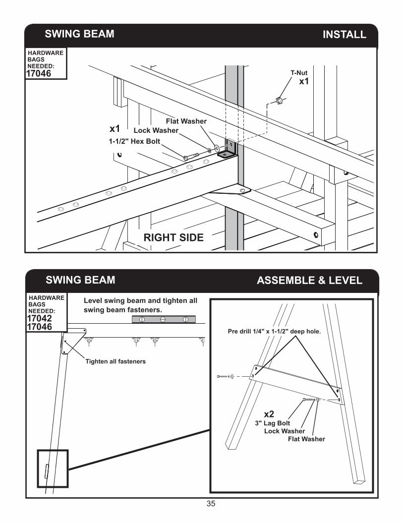
SWING BEAM INSTALL
2. Re-drill from opposite side using 7/16" bit.
1. Pre-drill using 3/16" bit.
SEE PAGE 8
SWING BEAM INSTALL
Flat Washer Lock Nut
6-1/2" Carriage Bolt
x1
x2
Torque Washer
9" Carriage Boltx1
x1
x12485RIGHT SIDE
NOTE: You may need to tap bolts with hammer to get through holes. Clean all debris from bolt threads before installing lock nuts.
Position swing beam assembly resting upon plate and align with holes.
RIGHT SIDE
HARDWARE BAGS NEEDED:17046
35
SWING BEAM INSTALL
x1T-Nut
Flat Washer
1-1/2" Hex BoltLock Washerx1
SWING BEAM ASSEMBLE & LEVEL
Level swing beam and tighten all swing beam fasteners.
Tighten all fasteners
Pre drill 1/4" x 1-1/2" deep hole.
x23" Lag Bolt Lock Washer Flat Washer
RIGHT SIDE
HARDWARE BAGS NEEDED:17046
HARDWARE BAGS NEEDED:17042 17046
36
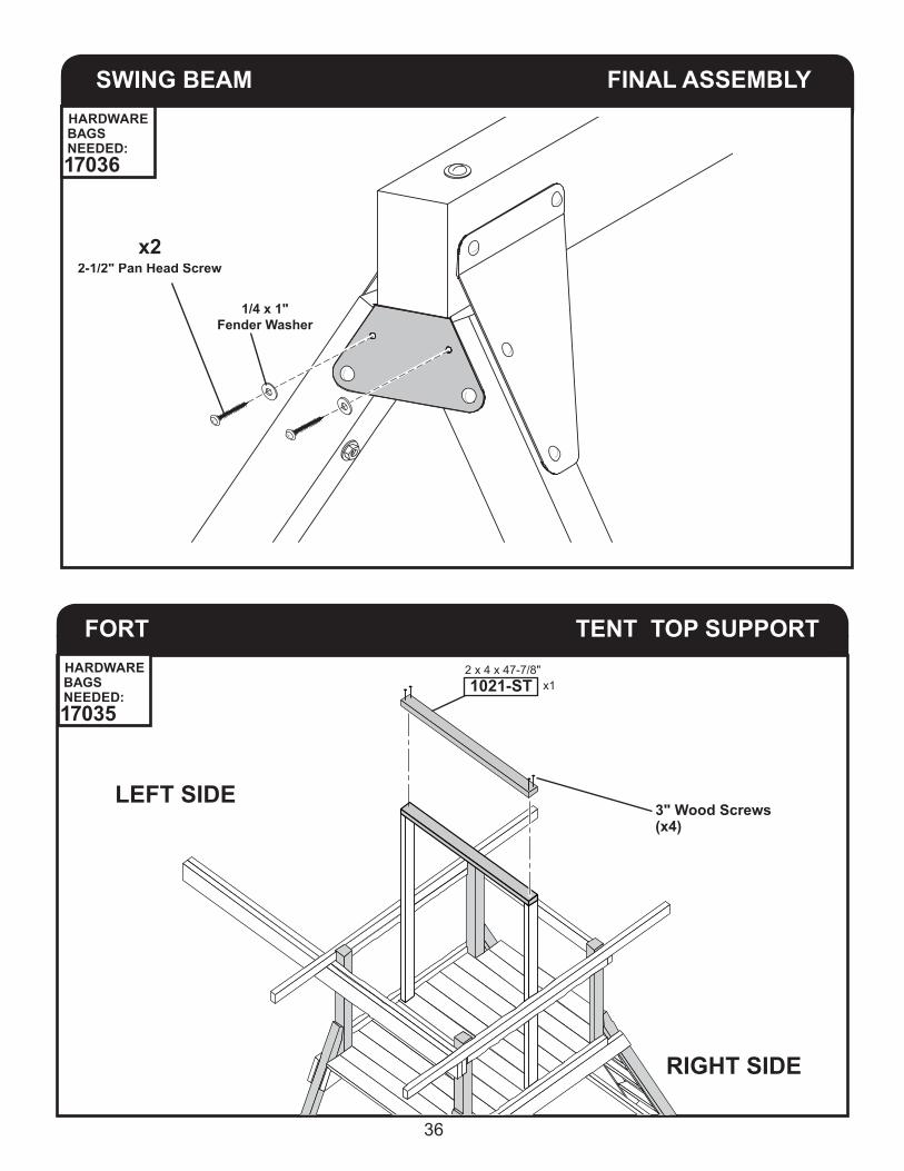
SWING BEAM FINAL ASSEMBLY
x22-1/2" Pan Head Screw
1/4 x 1"Fender Washer
FORT TENT TOP SUPPORT
RIGHT SIDE
LEFT SIDE3" Wood Screws (x4)
x12 x 4 x 47-7/8"1021-ST
HARDWARE BAGS NEEDED:17036
HARDWARE BAGS NEEDED:17035
37
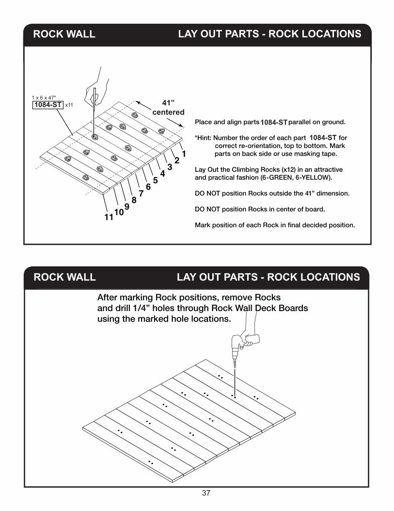
ROCK WALL
Place and align parts 1026-ST parallel on ground.
*Hint: Number the order of each part (1026-ST) for correct re-orientation, top to bottom. Mark parts on back side or use masking tape.
Lay Out the Climbing Rocks (x12) in an attractiveand practical fashion (6-GREEN, 6-YELLOW).
DO NOT position Rocks outside the 41” dimension.
DO NOT position Rocks in center of board.
Mark position of each Rock in final decided position.
1 2
3 4
5 6
7 8
9 10 11
1 x 6 x 47" x111084-ST
After marking Rock positions, remove Rocks and drill 1/4” holes through Rock Wall Deck Boards using the marked hole locations.
LAY OUT PARTS - ROCK LOCATIONS
LAY OUT PARTS - ROCK LOCATIONS
ROCK WALL
1084-ST
1084-ST
41”centered
38
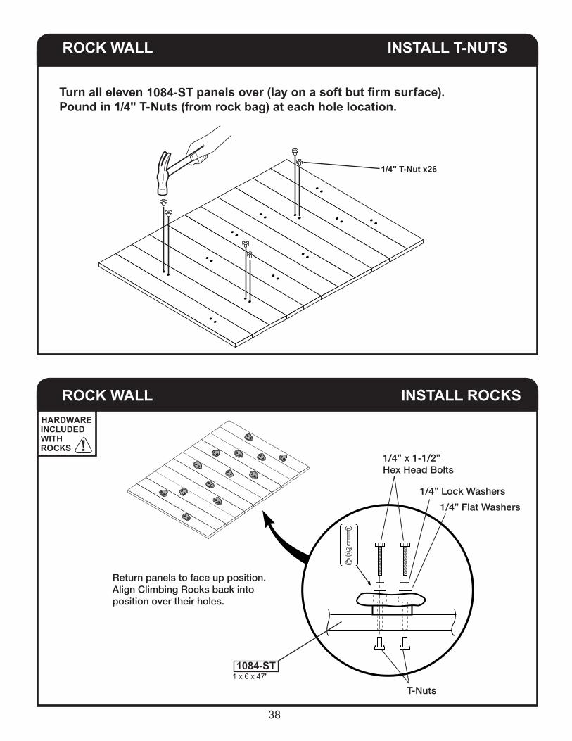
ROCK WALL INSTALL T-NUTS
Turn all eleven 1026-ST panels over (lay on a soft but firm surface).Pound in 1/4" T-Nuts (in separate bag 2452) at each hole location.
1/4" T-Nut x26
Return panels to face up position.Align Climbing Rocks back intoposition over their holes.
1/4” x 1-1/2”Hex Head Bolts
1/4” Lock Washers
T-Nuts
1/4” Flat Washers
ROCK WALL INSTALL ROCKS
1 x 6 x 47"1084-ST
Turn all eleven 1026-ST panels over (lay on a soft but firm surface).Pound in 1/4" T-Nuts (from rock bag) at each hole location.
1084-ST
HARDWARE INCLUDED WITH ROCKS

39
ROCK WALL
ROCK WALL
INSTALL
INSTALL 2-1/2"
Screwsx4
2-1/2" Screws(x40)
Secure rock wall cleat (2548-ST) with two 1-5/8" screws through two middle holes of lowest board. Make sure rock wall cleat (2548-ST) is centered and pulled tightly against back of lowest board.
Install top rock wall board (1084-ST) flush to edge of fort floor using four 2-1/2" screws as shown.Secure rock wall cleat (2548-ST) with two 1-5/8" screws centered through middle holes of (1084-ST) top board.
Upper end of rock wall cleat (2548-ST) should be 1/2" below top of (1084-ST) top board.Make sure rock wall cleat (2548-ST) is pulled tightly against back of (1084-ST) top board.
1/2"
1 x 6 x 47"1084-ST x1
3/4 x 2-1/2 x 59-1/2"2548-ST x1
2548-ST
1 x 6 x 47"1084-ST x10
Flush
Center
Center
1-5/8" Screws
x2
1-5/8" Screws
x2
RIGHT SIDE
RIGHT SIDE
LEFT SIDE
LEFT SIDE
HARDWARE BAGS NEEDED:17031 17034
HARDWARE BAGS NEEDED:17031 17034

40
ROCK WALL INSTALL
1-5/8" Screws
(x18)
Continue securing rock wall cleat (2548-ST) with eighteen 1-5/8" screws through middle holes of rock wall boards. Make sure rock wall cleat (2548-ST) is pulled tightly against back rock wall boards.
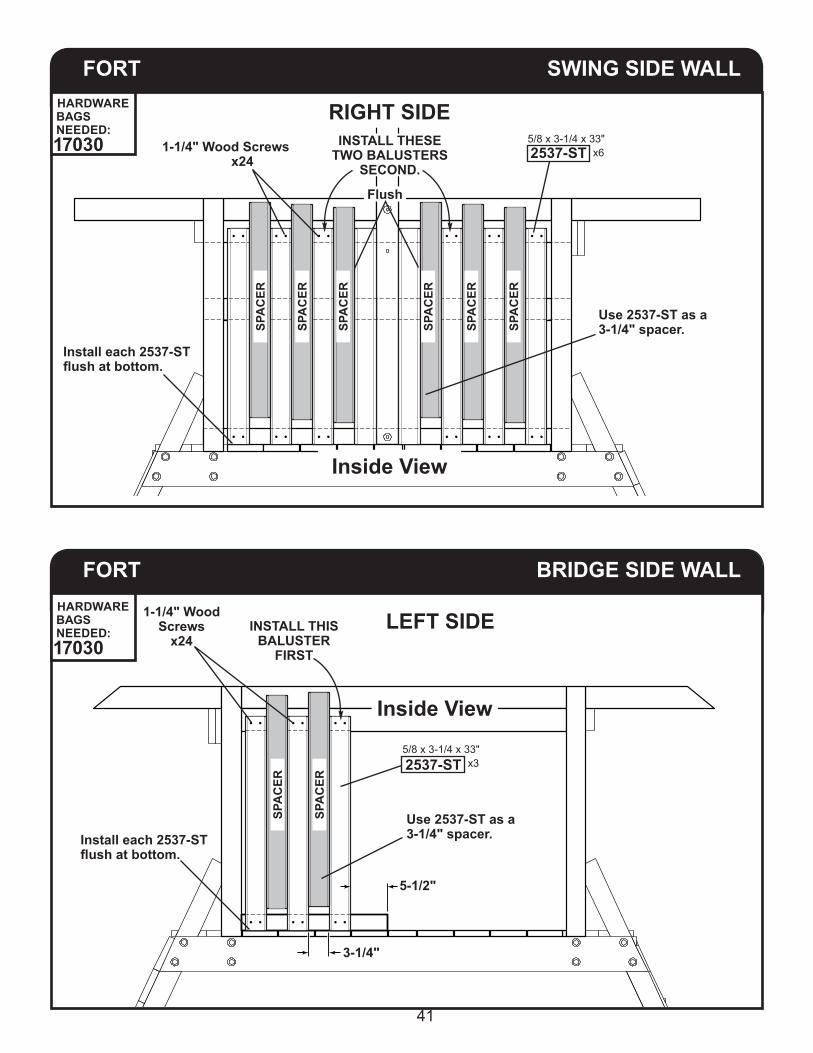
FORT SWING SIDE WALL
1-1/4" Wood Screws x8
Install 2537-ST flush at bottom.
Install 2537-ST flush against
board.
INSTALL THESE TWO BALUSTERS FIRST.
x25/8 x 3-1/4 x 33"
2537-ST
RIGHT SIDE
1 x 6 x 47"1084-ST x10
RIGHT SIDE
LEFT SIDE
LEFT SIDE
HARDWARE BAGS NEEDED:17031
HARDWARE BAGS NEEDED:17030
41
FORT SWING SIDE WALL
FORT BRIDGE SIDE WALL
SPA
CER
SPA
CER
SPA
CER
SPA
CER
SPA
CER
SPA
CER
SPA
CER
SPA
CER
1-1/4" Wood Screws x24
Use 2537-ST as a 3-1/4" spacer.
Install each 2537-ST flush at bottom.
Flush
x65/8 x 3-1/4 x 33"2537-ST
RIGHT SIDE
Inside View
INSTALL THESE TWO BALUSTERS
SECOND.
1-1/4" Wood Screws
x24
Use 2537-ST as a 3-1/4" spacer.
3-1/4"
5-1/2"
Install each 2537-ST flush at bottom.
LEFT SIDE
Inside View
INSTALL THIS BALUSTER
FIRST
x35/8 x 3-1/4 x 33"2537-ST
HARDWARE BAGS NEEDED:17030
HARDWARE BAGS NEEDED:17030
42
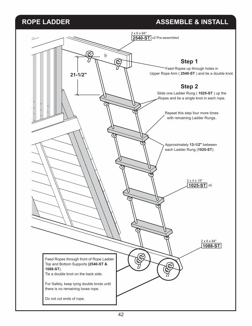
ASSEMBLE & INSTALLROPE LADDER
Feed Ropes up through holes in Upper Rope Arm ( 2540-ST ) and tie a double knot.
Slide one Ladder Rung ( 1025-ST ) up the Ropes and tie a single knot in each rope.
Repeat this step four more times with remaining Ladder Rungs.
21-1/2"
Approximately 13-1/2" betweeneach Ladder Rung (1025-ST).
Step 1
Step 2
Feed Ropes through front of Rope Ladder Top and Bottom Supports (2540-ST & 1088-ST).Tie a double knot on the back side. For Safety, keep tying double knots until there is no remaining loose rope.
Do not cut ends of rope.
2 x 4 x 19" x51025-ST
2 x 6 x 84" 1088-ST
2 x 6 x 84" 2540-ST x2 Pre-assembled

43
SWINGS INSTALL
53"Adjust chains at Top
Attach a Quick-Clip at the end of each swing and trapeze chain.Then, using the Quick-Clips, attach the swings and trapeze to the swing brackets on the swing beam, as shown below.
x12167
Attach Playset Plaqueusing One 1" Philips Head Screw(provided) at each corner of Plaque.
WS4885SWING
WS4885SWING
x1 WS1501TRAPEZE
All Spring Clips must not be removable unless using tools.
8" Minimum when occupied.Adjust chains at Top.
Quick Clip x6
Tighten all Quick Clips using hand tools.
Always use Quick Clip between chain and swing hanger for all chain connections and adjustments.
44
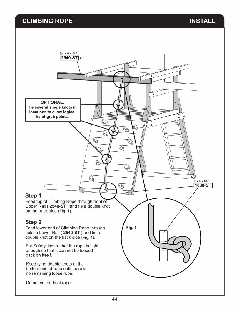
CLIMBING ROPE INSTALL
Fig. 1
Feed top of Climbing Rope through front of Upper Rail ( 2540-ST ) and tie a double knot on the back side (Fig. 1).
For Safety, insure that the rope is tight enough so that it can not be looped back on itself.
Feed lower end of Climbing Rope through hole in Lower Rail ( 2540-ST ) and tie a double knot on the back side (Fig. 1).
Keep tying double knots at the bottom end of rope until there is no remaining loose rope.
Do not cut ends of rope.
OPTIONAL:Tie several single knots in locations to allow logical
hand-grab points.
Step 1
Step 2
5/4 x 6 x 84" 2540-ST x2
2 x 6 x 84"1088-ST
45
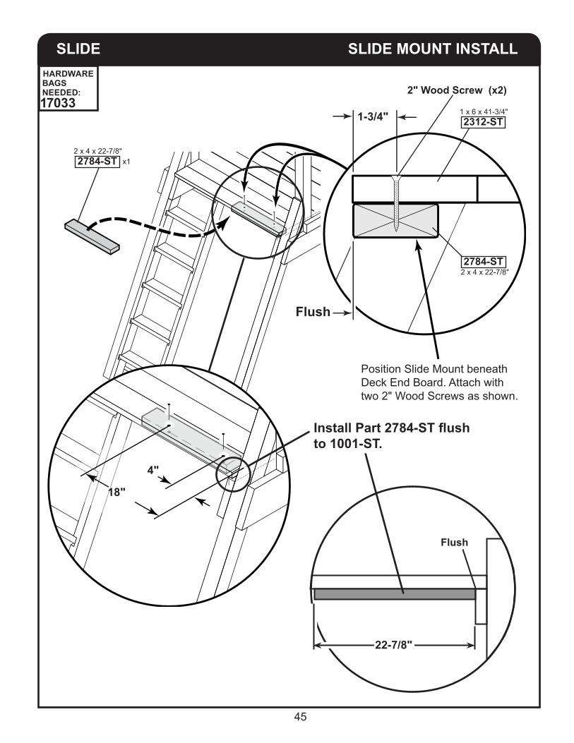
SLIDE SLIDE MOUNT INSTALL
4"
18"
2" Wood Screw (x2)
Flush
1-3/4"
Position Slide Mount beneathDeck End Board. Attach withtwo 2" Wood Screws as shown.
Install Part 2784-ST flush to 1001-ST.
Flush
22-7/8"
2 x 4 x 22-7/8"2784-ST
2 x 4 x 22-7/8" x12784-ST
1 x 6 x 41-3/4" 2312-ST
HARDWARE BAGS NEEDED:17033

46
SLIDE
SLIDE
MEASURE
MEASURE
Slide
Slide
Flush
Flush
4"
2"
1 x 6 x 41-3/4"2312-ST
1 x 6 x 41-3/4"2312-ST
5/4 x 6 x 66-3/8"1085-ST
5/4 x 6 x 66-3/8"1085-ST
2 x 4 x 22-7/8" 2784-ST
2 x 4 x 22-7/8" 2784-ST
NOTE: IF SLIDE HAS THREE HOLES, INSTALL 4" FROM FRONT OF DECK.
NOTE: IF SLIDE HAS FOUR HOLES, INSTALL 2" FROM FRONT OF DECK.

47
SLIDE DRILL
Slide
Drill 1/8” holes at dimples through Slide and 2312-ST into 2784-ST (1 inch deep).
5/4 x 6 x 41-3/4"2312-ST
NOTE: DEPENDING ON YOUR SLIDE, INSTALL WITH THREE OR FOUR SCREWS.
SLIDE MOUNTING SCREWS2-1/2" Pan Head Wood Screw (x3 or x4)
1/4" x 1" Fender Washer (x3 or x4)
5/4 x 6 x 41-3/4"2312-ST
HARDWARE BAGS NEEDED:17036

48
SLIDE SURFACING MATERIAL (not supplied)
Apply Surfacing Material at recommended depth, or deeper.
Hammer 1015 Ground Stake into ground on either side of slide and attach to slide wall using (2) 1-1/4" Screws.
1 x 1-3/8 x 17"
1015
SAFETY HANDLES INSTALLAttach Left and Right Safety Handles to the Step Ladder Rails with two 1/4" x 1-1/2" Lag Bolts through 1/4" Flat Washers. Attach third Safety Handle as shown.
The height of the handles is to be determined by the customer - depending on the age of the child, etc.
Flat Washer
1/8" Pre-Drill (Do not drill
through.)1-1/2" Lag Bolts
DO NOT OVER-TIGHTEN LAG BOLTS
x3WS 4410
HARDWARE BAGS NEEDED:17030

49
STAKES
STAKE STAKE
STAKESTAKE
STAKE
STAKE
Pound in Stakes (1015) at 45 degree angle.
Make sure all base pieces, uprights and slideare resting flat on the ground.
It may be necessary to loosen the soil beneath Playset to make everything level.
2-1/2" Wood Screws (x4)
2-1/2" Wood Screws (x4)
2-1/2" Wood Screws (x4)
Stakes Flush with TOP.
Stakes Flush with SIDES.
Stakes Flush with TOP.
1 x 1-3/8 x 17" x21015
1 x 1-3/8 x 17" x21015
1 x 1-3/8 x 17" x21015
HARDWARE BAGS NEEDED:17034

50
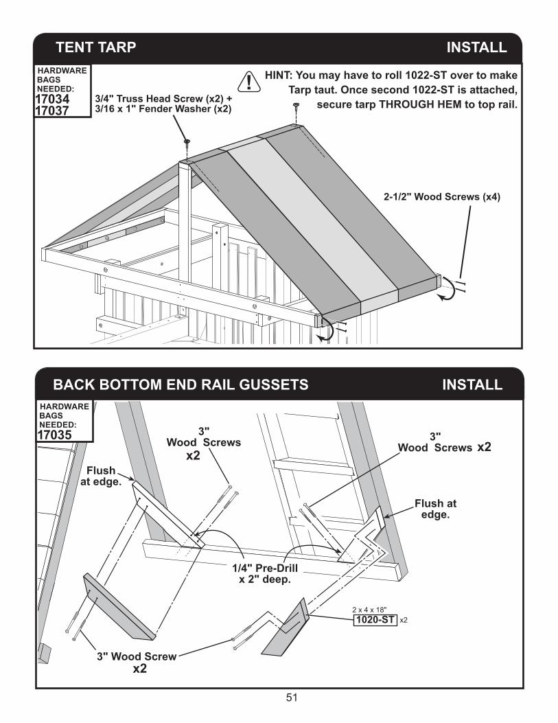
TENT TARP INSTALL
2-1/2" Wood Screws (x4)
Secure 1022-ST to end rail and drape tarp over top rail .
TENT TARP INSTALLSecure Tent Tarp at Five Areas as shown, equal distance apart on Tent Frame End Rail (1022-ST).
Install screwsthrough hemfor strength.
3/4" Truss Head Screw (x10)
3/16" x 1" Fender Washer (x10)
End Rail
2 x 6 x 51"1022-ST
BEGIN HERE
1-1/2"
1-1/2"
x1
Repeat step on other side of Tarp to install second 1022-ST.
HARDWARE BAGS NEEDED:17034
HARDWARE BAGS NEEDED:17037
51
TENT TARP INSTALL
HINT: You may have to roll 1022-ST over to make Tarp taut. Once second 1022-ST is attached,
secure tarp THROUGH HEM to top rail.
2-1/2" Wood Screws (x4)
3/4" Truss Head Screw (x2) + 3/16 x 1" Fender Washer (x2)
INSTALLBACK BOTTOM END RAIL GUSSETS
3"Wood Screws 3"
Wood Screws
Flush at edge.
Flushat edge.
3" Wood Screw
x2 x2
x2
1/4" Pre-Drillx 2" deep.
2 x 4 x 18" x21020-ST
HARDWARE BAGS NEEDED:17034 17037
HARDWARE BAGS NEEDED:17035

52
INSTALLSWING SAFETY BARRIER
INSTALLROPE LADDER BOTTOM SUPPORT GUSSETS
1/4" Pre-Drillx 2" deep.
2 x 4 x 18" x21020-ST
3"Wood Screws
3"Wood Screws
Flush at edge.
Flushat edge.
3" Wood Screw
x2 x2
x2
RIGHT SIDE
3" Lag Bolt x4
Lock Washer
Pre drill 1/4" x 1-1/2" deep at both sides.
Do not drill through.
Flat Washer
LEVEL
Flushwith leg.
5/4 x 6 x 95" x12541-ST
HARDWARE BAGS NEEDED:17035
HARDWARE BAGS NEEDED:17047

53
THE TIRE SWING KIT MAY BE INSTALLED NOW.REFER TO THE TIRE SWING INSTALLATION MANUAL.
STOP
BEGIN TOWER & BRIDGE ASSEMBLY
LEFT SIDE
RIGHT SIDE
FRONT SIDE
BACK SIDE
USE HARDWARE BAG 2642packed in your TOWER WOOD KIT for assembly.

54
TOWER FRAME 1
TOP
After installing all T-nuts,flip each 2329-W end-over-end
lengthwise, as shown.
Eventual parts shown for positioning only(don’t install yet!).
IMPORTANT!Orient both parts 2329-W as shownfor T-nut installation. Pay close attention to hole locations!
T-Nut x10Install T-Nuts BEFORE assembling Tower.
T-Nuts should be installed toward the INSIDE of tower legs (2329-W).
56-1/2"
57-3/8"
3-3/4"
1-3/4"
96"
TOWER FRAME 1
TOP
3-3/4" Hex Bolt x2
Lock Washer
Flat Washer
T-NutPre-Installed T-Nuts downward!
3" Wood Screw x2T-Nut
Flush
Flush
5-1/2" Hex Bolt x2
Lock Washer
Flat Washer
56-1/2"
2 x 4 x 84"2336-ST
5/4 x 6 x 46-3/8"1124-ST
2 x 4 x 45-3/8"1117-ST
1-3/4"
Board 1124-ST will overhang 1-3/8" this side.
2329-W x23 x 3 x 95"
2329-W x23 x 3 x 95"
55
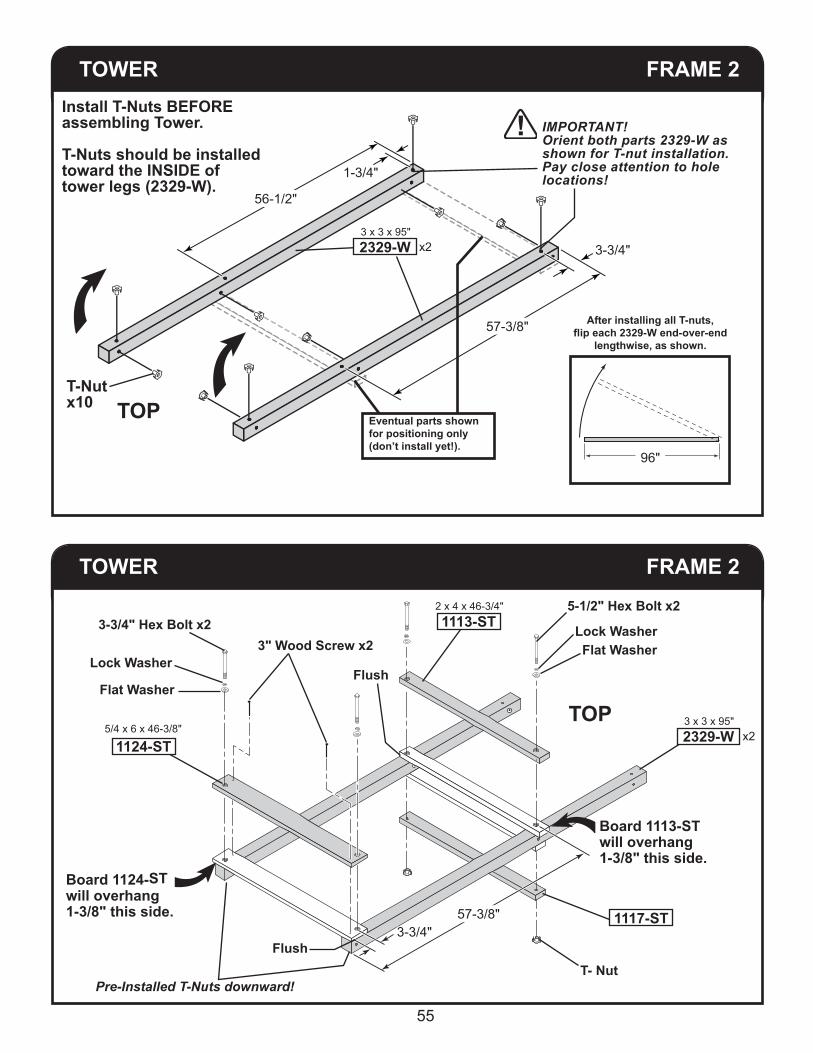
TOWER FRAME 2
TOP
IMPORTANT!Orient both parts 2329-W as shown for T-nut installation. Pay close attention to hole locations!
T-Nut x10
Install T-Nuts BEFORE assembling Tower.
T-Nuts should be installed toward the INSIDE of tower legs (2329-W).
56-1/2"
57-3/8"
3-3/4"
1-3/4"
Eventual parts shown for positioning only(don’t install yet!).
After installing all T-nuts,flip each 2329-W end-over-end
lengthwise, as shown.
96"
TOWER FRAME 2
TOP
5-1/2" Hex Bolt x2
Lock WasherFlat Washer
Pre-Installed T-Nuts downward!T- Nut
3" Wood Screw x23-3/4" Hex Bolt x2
Lock Washer
Flat Washer
1124-ST
1117-ST
2 x 4 x 46-3/4"1113-ST
Flush
Flush
57-3/8"3-3/4"
2329-W
Board 1113-ST will overhang 1-3/8" this side.
Board 1124-ST will overhang 1-3/8" this side.
5/4 x 6 x 46-3/8" x23 x 3 x 95"
2329-W x23 x 3 x 95"

56
TOWER ASSEMBLE
Get a helper to steadythe Tower Frame duringthis step.
4" Hex BoltLock Washer
Flat Washer
LEFT SIDE
FRONT SIDE
TOWER ASSEMBLE
4" Hex Bolt
Lock WasherFlat Washer
TOP
1113-ST
Will be flush with top of
board.
2 x 4 x 46-3/4"

57
TOWER ASSEMBLE
TOWER ASSEMBLE
3-3/4" Hex Bolt x4
Lock Washer
Flat Washer
3" Wood Screw x4
4" Hex Bolt
Lock WasherFlat Washer
FRONT SIDE
LEFT SIDE
FRONT SIDE
1115-ST
1124-ST
1124-ST
Flush
5/4 x 6 x 46-3/8"
5/4 x 6 x 46-3/8"
2 x 4 x 46-3/4"

58
TOWER DECK
TOWER FRAME
3" Wood Screws x4
17-3/8"
17-3/8"
Flush
Flush
BACK SIDE
FRONT SIDE
Center between 2329-W and 2329-W.BACK SIDE
FRONT SIDE
2-1/4"4-1/2"
Install this panel first.
2-1/2" Wood Screws x6
2 x4 x 45-3/8" x11116-ST
5/4 x 5 x 47" x11096-ST
2329-W2329-W
2329-W2329-W

59
BRIDGE FRAME
Pre-Installed T-Nut
TOWER DECK
2-1/2" Wood Screws x48
(spaced evenly)
BACK SIDE
FRONT SIDE
(pre-installed)
Lock Washer
Flat Washer
1-1/2" Hex Bolt
FRONT SIDE
2327-ST
5/4 x 6 x 47" x61094-ST
1096-ST
5/4 x 4-1/2 x 39" x22327-ST
2336-ST
x12084

60
BRIDGE
BRIDGE
FRAME
FRAME
27-5/8"
27-5/8"
1-11/16" From edge of corner post.
1-11/16"From edge of corner post.
7/16" Pre-Drill through.
1-3/4"
1-13/16" Measure and mark four locations.
LEFT SIDE

61
BRIDGE
FlushFlush
1-1/2" Hex Bolt
Lock Washer
Flat Washer
TG
JOIST
T-Nut
2 x 4 x37-1/4"x11118-ST
x22084
BRIDGE FRAME
19"Mark both locations.
From inside of Corner Post. 6"
3-11/16"

62
7/16” Drill Through
TA
1-1/2” Hex BoltLock Washer
T-NutFlush
BRIDGE
7/16" Drill Through
JOIST
1-1/2" Hex BoltLock Washer
Flat Washer
T-NutFlush
2336-ST
Flat Washer
BRIDGE
1-1/2" Hex BoltLock Washer
Flat Washer
T-Nut
T-Nut
JOIST
Flush1118-ST
PLAYSET DECK

63
BRIDGE JOIST
2-1/2" Wood Screwsx28
Install First
Flush to uprights
1 x 6 x 23-1/2" x71121-ST
FRONT SIDE
BRIDGE DECK
1121-ST
Flush all panels.
2-1/2" Hex Boltx4
Flat Washer
Lock WasherT-Nut
T-Nut
T-Nut
2334-ST1-3/8 x 3-3/8 x 43-1/2"
x2

64
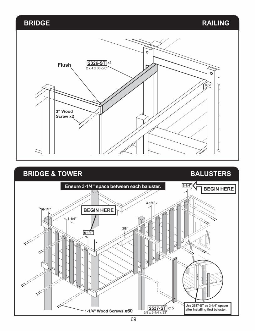
RAILING
4" Hex BoltLock Washer
x6
Flat Washer
ORIENT BOARDS SO TOPS ARE FLUSH AT
CORNERS.
2 x 4 x 85-3/8"2313-ST
FRONT SIDE
Flush
Flush
x1
1113-ST x22 x 4 x 46-3/4"
1113-STx22 x 4 x 46-3/4"
BRIDGE
BRIDGE
RAILING
8-3/16"
1-1/4"
2 x 4 x 85-3/8"
2313-ST
65
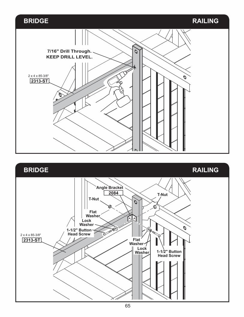
BRIDGE
BRIDGE
RAILING
RAILING
2 x 4 x 85-3/8"
2313-ST
7/16" Drill Through.KEEP DRILL LEVEL.
2 x 4 x 85-3/8"
2313-ST Flat Washer
Lock Washer 1-1/2" Button
Head Screw
T-Nut
Angle Bracket2084
Flat Washer
Lock Washer
1-1/2" Button Head Screw
T-Nut

66
BRIDGE RAILING SUPPORT
2-1/2" Hex BoltLock Washer
Flat WasherT-Nut BACK SIDE
1-3/8 x 3-3/8 x 34-7/8"1119-ST x1
BRIDGE RAILING
4" Hex BoltLock Washer
Flat Washer
2-1/2" Hex BoltLock Washer
Flat Washer
FRONT SIDE 2 x 4 x 25-1/4"1114-ST
Flush
counterbore on underside.

67
BRIDGE RAILING
4"
1-1/2" Button Head Screw
Lock Washer
T-Nut
Angle BracketFlat Washer2084
x11-3/8 x 3-3/8 x 38-5/8"
2326-ST
BRIDGE RAILING SUPPORT
8-3/16"
1-1/4"

68
BRIDGE RAILING
x12 x 4 x 38-5/8"
2326-ST Flat
Washer Lock Washer
1-1/2" Button Head Screw
T-Nut
BRIDGE RAILING SUPPORT
7/16" Drill Through
69
RAILING BRIDGE
Flush
3" WoodScrew x2
x12 x 4 x 38-5/8"2326-ST
BALUSTERS
3-1/4"
6-1/4"
3/8"
3-1/4"
Use 2537-ST as 3-1/4" spacerafter installing first baluster.
BEGIN HERE
BEGIN HERE
6-1/4"
2-1/4"Ensure 3-1/4" space between each baluster.
1-1/4" Wood Screws x60
SPAC
ER
x15 5/8 x 3-1/4 x 33"
2537-ST
BRIDGE & TOWER

70
1-1/4" Wood Screwsx20
6-1/4"
7-1/2"
3/8"
3/8"
BACK SIDE
3-1/4"
2537-ST
2537-ST
3-1/4"
BALUSTERSTOWER
3-1/4"2-1/4"
BRIDGE BALUSTERS
3/8"
Ensure 3-1/4" space between each baluster.
x5 2537-ST
1-1/4" Wood Screws
x20
SPA
CER
BEGIN HERE
Ensure 3-1/4" space between each baluster.
71
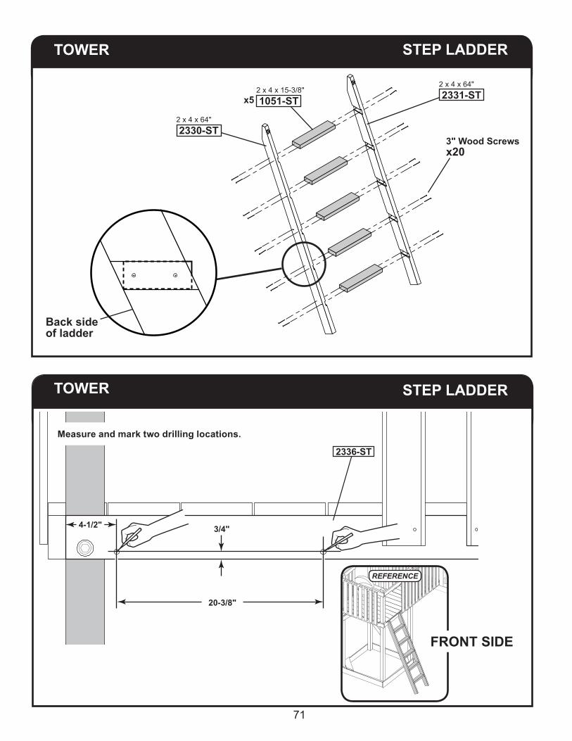
STEP LADDER
3" Wood Screwsx20
2 x 4 x 64"2331-ST
2 x 4 x 64"2330-ST
x52 x 4 x 15-3/8"1051-ST
Back side of ladder
STEP LADDER
20-3/8"
FRONT SIDE
REFERENCE
2336-ST
4-1/2" 3/4"
Measure and mark two drilling locations.
TOWER
TOWER

72
TOWER STEP LADDER
Pre-drill two 1/4" pilot holes at marked locations. Re-drill holes from opposite side using 3/8" bit. Pre-drill two 1/4" pilot holes at marked locations on 2336-ST. Re-drill holes from opposite side using 3/8" bit.
FRONT SIDE
TOWER STEP LADDER
5/16" x 1-1/2"Button Head
Bolt
5/16" Lock Washer
5/16" Flat Washer
5/16" T-Nut
x2
x2
Install from behind.
Flush at bottom
Flush at bottom
FRONT SIDE
x22412Install (2) 2412 brackets with 5/16" fasteners. Adjust brackets so they are flush with bottom of 2336-ST tower deck support.

73
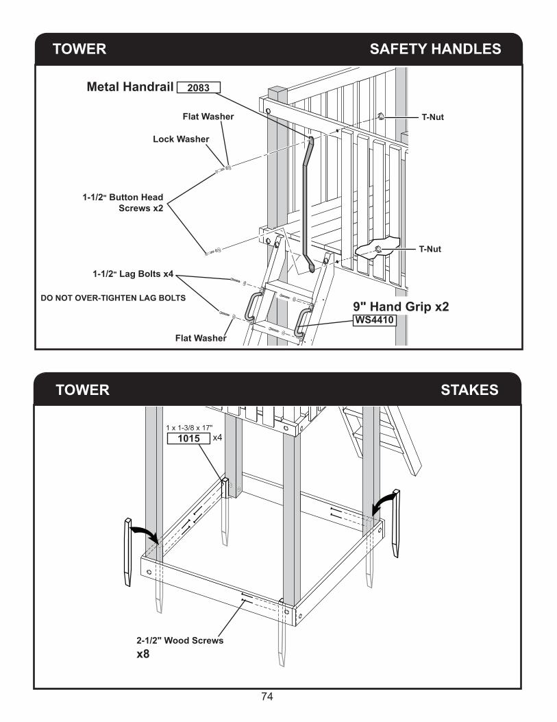
TOWER SAFETY HANDLES
Measure, Mark and 7/16" Pre-Drill Through.
24-1/2"
24-1/2"
1-11/16"
1-11/16"
TOWER STEP LADDER
Place ladder flush at top of 2336-ST. Install 5/16" fasteners through brackets and holes in ladder. Keep ladder flush with top of 2336-ST.
FRONT SIDE
5/16" x 1-1/2"Button Head
Bolt
5/16" Lock Washer
5/16" Flat Washer
5/16" T-Nut x2
x2
Flush at TOP
74
TOWER SAFETY HANDLES
Lock Washer
Flat Washer
1-1/2" Lag Bolts x4
Flat Washer
Metal Handrail
9" Hand Grip x2
1-1/2" Button Head Screws x2
2083
WS4410
DO NOT OVER-TIGHTEN LAG BOLTS
T-Nut
T-Nut
TOWER STAKES
2-1/2" Wood Screwsx8
x41 x 1-3/8 x 17"
1015

75
TOWER SAND BOX SEATS
3" Wood Screwsx8
Flush
Flush
5/4 x 6 x 22-1/2"1120-ST
TOWER GUSSETS
2329-ST
x42 x 4 x 18"1020-ST
1/4" Pre-Drill2" deep.
x2
2-1/2"Wood Screws
Flush atoutside edges.
3" Wood Screws
x2
x2

76
STEP LADDER LADDER BLOCK
BACK SIDE
2-1/2" Screwsx4 Flush
1 x 4 x 17"x12222-ST
2222-ST
CENTER IN OPENING.
INSTALLSLIDE
2-1/4"
5"
TOPVIEW
Dimples2 x 4 x 45-3/8"1117-ST
2 x 4 x 46-3/4"1113-ST
Slide
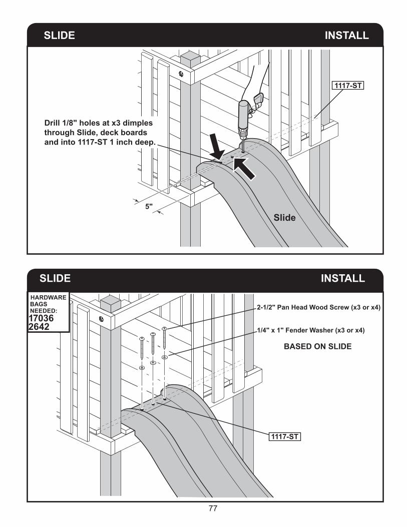
77
SLIDE INSTALL
5"
Drill 1/8" holes at x3 dimples through Slide, deck boards and into 1117-ST 1 inch deep.
Slide
1117-ST
INSTALLSLIDE
BASED ON SLIDE
1117-ST
2-1/2" Pan Head Wood Screw (x3 or x4)
1/4" x 1" Fender Washer (x3 or x4)
HARDWARE BAGS NEEDED:17036 2642
78
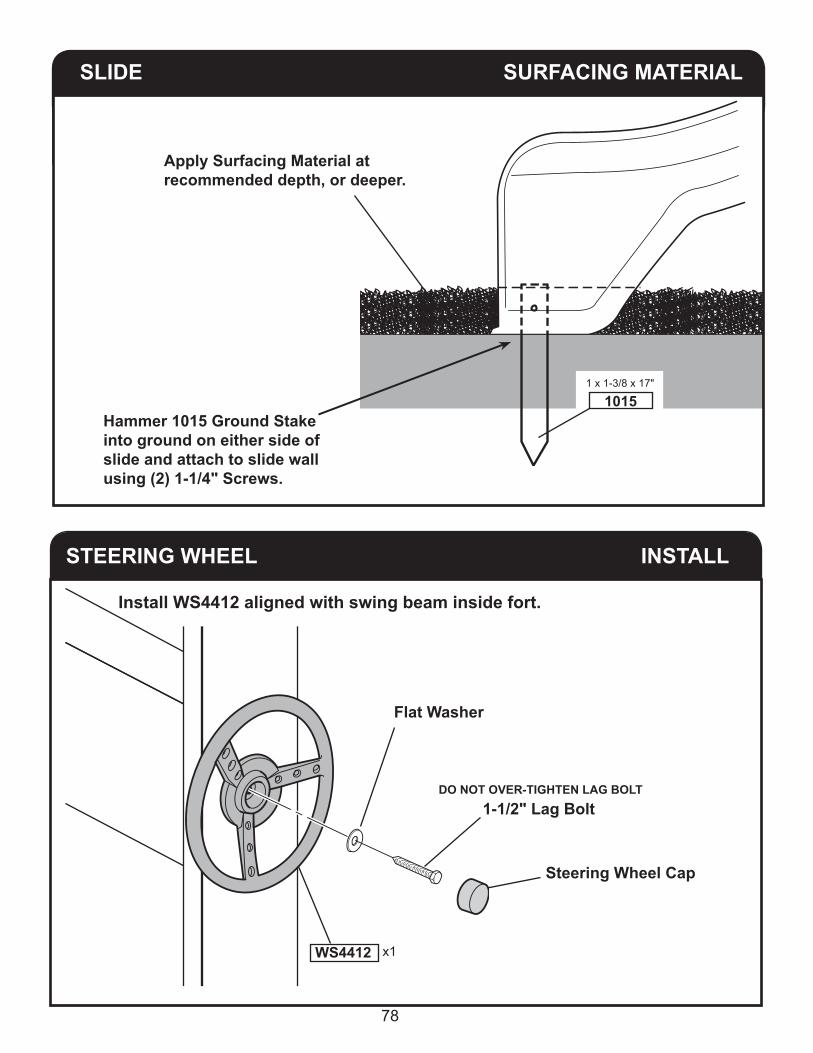
STEERING WHEEL INSTALL
1-1/2" Lag Bolt
Flat Washer
Steering Wheel Cap
x1WS4412
Install WS4412 aligned with swing beam inside fort.
DO NOT OVER-TIGHTEN LAG BOLT
HARDWARE BAGS NEEDED:17048
SLIDE SURFACING MATERIAL
Apply Surfacing Material at recommended depth, or deeper.
1 x 1-3/8 x 17"
1015Hammer 1015 Ground Stake into ground on either side of slide and attach to slide wall using (2) 1-1/4" Screws.

79
TELESCOPE INSTALL
Telescope
TelescopeBracket
Any Top Rail
1-1/4" Screws
x1 WS 4610
(This space intentionally left blank.)

80
WARRANTY
Backyard Play Systems warrants the following:1. All wood and plastic (polymer) coated wood components have a Limited Lifetime Warranty.
• Treated Wood - Backyard Play Systems will replace treated wood which becomes structurally unfit due solely to damage caused by fungal decay or termites. • Plastic (Polymer) Coated Woodguard TM –
Backyard Play Systems will replace Woodguard TM components which become structurally unfit due solely to damage caused by fungal decay or termites. The plastic coating color can fade naturally over time. This warranty excludes color fading.
2. All non-wood components* have a three year Limited Warranty. *Ropes carry a one year Limited Warranty.3. Installation labor has a three year Limited Warranty applicable on playsets installed by Backyard Play Systems. Labor warranty does NOT apply to Do-It-Yourself playset kits or kits installed by a third party.
Backyard Play Systems will repair, replace or pay for the affected part at our discretion. In no event shallBackyard Play Systems pay the cost of labor or installation or any other costs related thereto.
Non-residential use of the system is prohibited and will void this warranty as the system is designedfor residential use only.
ConditionsThe warranty is effective only when:1. The unit has been erected in accordance with the assembly instructions. • Plastic end caps and hole plugs have been properly installed on plastic coated wood.2. The unit has been regularly and properly maintained and inspected.3. The failure occurs when the unit is owned by the original purchaser.4. This warranty is non-transferable5. Backyard Play Systems has received a copy of your original proof of purchase with any claims in writing.6. Backyard Play Systems has had reasonable opportunity during the sixty (60) days following the receipt of notification to inspect and verify the failure prior to commencement of any repair work.7. “Significant color changes” to wood components is at the discretion of Backyard Products and require proof in the form of photographs or inspection by Backyard Play Systems.
Wooden components may have imperfections such as checks and knots. These are naturalblemishes and imperfections which are inherent to wood. The imperfections not resulting in structuralfailure are not covered under this warranty.
RequirementsTo validate your warranty it is necessary to go online and register your product. And also to maintain and inspect your playset regularly. Regularly is defined as once per start and end of season.
Claim ProcedureTo make a claim under this warranty, you can either call 1-866-890-2211 or prepare a letter. Please have ready the information below when you call or include the information in writing:
1. The model and size of the product.2. A list of the part(s) for which the claim is made.3. Proof of purchase of the Backyard Play Systems item, as shown on the original invoice.4. Run Code, as listed on the instructions.
Mail the above information to:Backyard Play Systems
Attn: Customer Service 1000 Ternes Dr. Monroe, MI 48162
WARRANTY REGISTRATION:Please complete your warranty registration to properly validate your product warranty registration.Register your product online at: www.OnlineWarranty.net
81
Please feel free to call our Consumer Help Line Toll Free
1-866-890-2211April through October M - F 8:00 AM to 6:00 PM EST
Saturday 8:30 AM to 4:30 PM ESTNovember through March M - F 8:00 AM to 5:00 PM EST
No warranty is offered on the following: (1) equipment subject to abuse, negligence, improper installation, vandalism, acts of God, unauthorized alteration or attachment to equipment other than our own: or (2) equipment subjected to improper use, service or repair by customer or any third party.
To the maximum extent permitted by law, this warranty and the remedies set forth herein are exclusive and expressly in lieu of all other warranties, expressed or implied, including warranties of merchantability or fitness for a particular purpose. If Backyard Play Systems cannot disclaim or exclude implied warranties under applicable law, then to the extent possible any claims under any such implied warranties shall expire on expiration of the applicable warranty period. Some states do not allow limitations on how long an implied warranty lasts, so the above limitation may or may not apply to you. Backyard Play Systems does not assume, or authorize any person to assume for us, any other liability in connection with the sale of our products.
To the maximum extent of the law, Backyard Play Systems assumes no responsibility for incidental or consequential damages which may arise from the purchase or use of our playset or equipment. Some states do not allow the exclusion or limitation of incidental or consequential damages, so the above limitation or exclusion may not apply to you.
If any provision of this limited warranty is invalid, void or unenforceable in any instance or respect, the unenforceable provision will be severed and reformed to effect the intent of this limited warranty to the maximum extent possible, and the remaining provisions shall continue in full force and effect and shall be enforced to the full extent permitted by law.
This warranty gives you specific legal rights, and you may also have other rights which vary from state to state.
WARRANTY TERMS MAY VARY OUTSIDE THE U.S.A.
This manual is your warranty certificate. Please retain your original proof of purchase and this manual for any warranty claims.
WARRANTY


![Index [] · 2018-02-22 · • Female Casual Moves • CC Fantasy Playset: Assassins • CC Fantasy Playset: Assassins Bonus. 3 ... use in business presentations, training projects,](https://static.fdocuments.us/doc/165x107/5ed998e41b54311e7967dc30/index-2018-02-22-a-female-casual-moves-a-cc-fantasy-playset-assassins.jpg)

![Christmas Village Playset Printable 1109[1]](https://static.fdocuments.us/doc/165x107/55235c094a7959575e8b4c6c/christmas-village-playset-printable-11091.jpg)