AdvanTag 9100 · Figure 5 AdvanTag 9100 Gateway ... Special tags are used in this document to alert...
52
Rev. A Date: 06/05/2003 Printed on Standard Paper P/N: 2000-3160-02 Copyright ©2003 Asyst Technologies, Incorporated All rights reserved. AdvanTag 9100 AdvanTag Gateway Technical Manual
Transcript of AdvanTag 9100 · Figure 5 AdvanTag 9100 Gateway ... Special tags are used in this document to alert...

Rev. A Date: 06/05/2003Printed on Standard PaperP/N: 2000-3160-02
Copyright ©2003Asyst Technologies, Incorporated All rights reserved.
AdvanTag 9100AdvanTag GatewayTechnical Manual
AdvanTag 9100/Gateway Technical ManualDisclaimersa
DisclaimersThis manual may not be reproduced, either wholly or in part, for any reason whatsoever, without prior written permission from Asyst Technologies, Inc. (“Asyst”). Material contained in this manual is provided for informational purposes and is subject to change without notice.
If this manual is marked “Preliminary” or “Draft,” then Asyst has not yet released a final version of the manual and the manual is likely to be incomplete and will be revised. Contact Asyst at the address below to obtain a final copy of the manual.
Manual InformationPCN: E12464Part Number: 2000-3160-02Date: 06/05/2003Release: xPrinting Description: Printed on Standard Paper.
Asyst Technologies, Inc.48761 Kato RoadFremont, California 94538Telephone: (510) 661-5000FAX: (510) 661-5166Technical Support: 1-800-342-SMIF
TrademarksAsyst, the Asyst logo(s), FLOUROTRAC, KPOD, ADU and MANUAFACTURING CONNECTIVITY are registered trademarks ® of Asyst Technologies, Inc.
VERSAPORT, PLUS, INX, ADVAN-TAG, LINK MANAGER, SMART-TAG, SMART-STATION, SMART-STORAGE, SMART-TRAVELER, SMART-COMM, AXYS, FASTRACK, FASTMOVE, FASTLOAD, FASTORE are trademarksTM of Asyst Technologies, Inc.
All other product and company names mentioned herein may be trademarks and/or service marks of their respective owners.
Equipment ModificationAny change, alteration, or modification to this equipment, as well as use of this equipment in a manner inconsistent with its intended use will void this equipment’s warranty and may render this equipment unsafe for use or unfit for its intended purposes.
Training and LanguagesUser training for equipment operation and maintenance is conducted in English. Translators are available on an as needed basis. English versions of the manuals and other technical materials are provided and reviewed during the training. Please contact the Asyst Training department or http://www.asyst.com for the training schedule and signup requirements.
WarrantyFor warranty information, see Asyst’s Standard Terms and Conditions.
Rev. A Released Page i

AdvanTag 9100/Gateway Technical ManualReader Comments a
Reader CommentsWe welcome your comments regarding this manual. Your comments and suggestions help us to improve our publications.
Please send comments and suggestions to:
Asyst Technologies, Inc.Technical Publications Manager48761 Kato Rd.Fremont CA 94538
Or fax: Attention—Tech Pubs Manager at 1-510-661-5185
Or email: [email protected]
Include the following:
Name:
Company:
Contact Phone # (in case we have questions):
Email:
Document Information (Name of document, Part Number, Revision):
Location of comment (page number or other reference):
Comments: (The more specific the comments, the more useful they are to us.)
Thank you for helping to improve the manuals and to maintain accuracy.
Page ii Released Rev. A

a
Acronym ListAMHS Automated Material Handling System
ASCII American Standard Coding for Information Interchange
ATR AdvanTag Reader
CAN Control Area Network
CIM Computer-Integrated Manufacturing
EMF Electromagnetic Field
EMI Electromagnetic Interference
EMO Emergency (Machine) Off
ESD Electrostatic Discharge
MID Material IDentification
OEM Original Equipment Manufacturer
PN or P/N Part Number
RFID Radio Frequency IDentification
SECS Semiconductor Equipment Communication Standard
SEMI Semiconductor Equipment and Materials International
SMIF Standard Mechanical Interface
Rev. A Released Page iii

AdvanTag 9100/Gateway Technical Manual
a
Page iv Released Rev. A

Rev. A Released Page v
aRevision History
Date Author Version Revision Information
06/05/2003 Royden Tonomura A Original version - release ECN E12464

Page vi Released Rev. A
AdvanTag 9100/Gateway Technical Manual
a

AdvanTag 9100/Gateway Technical ManualTable of Contentsa
Table of ContentsDisclaimers . . . . . . . . . . . . . . . . . . . . . . . . . . . . . . . . . . . . . . . . . . . . . . . . . . . . . . .iManual Information . . . . . . . . . . . . . . . . . . . . . . . . . . . . . . . . . . . . . . . . . . . . . . . . .iTrademarks . . . . . . . . . . . . . . . . . . . . . . . . . . . . . . . . . . . . . . . . . . . . . . . . . . . . . . .iEquipment Modification. . . . . . . . . . . . . . . . . . . . . . . . . . . . . . . . . . . . . . . . . . . . . .iTraining and Languages . . . . . . . . . . . . . . . . . . . . . . . . . . . . . . . . . . . . . . . . . . . . .iWarranty . . . . . . . . . . . . . . . . . . . . . . . . . . . . . . . . . . . . . . . . . . . . . . . . . . . . . . . . .iReader Comments . . . . . . . . . . . . . . . . . . . . . . . . . . . . . . . . . . . . . . . . . . . . . . . . ii
Acronym List. . . . . . . . . . . . . . . . . . . . . . . . . . . . . . . . . . . . . . . . . . . . . . iii
Revision History . . . . . . . . . . . . . . . . . . . . . . . . . . . . . . . . . . . . . . . . . . . .v
Preface . . . . . . . . . . . . . . . . . . . . . . . . . . . . . . . . . . . . . . . . . . . . . . . . . . 1Purpose and Audience . . . . . . . . . . . . . . . . . . . . . . . . . . . . . . . . . . . . . . . . . . . . . 1About this Manual . . . . . . . . . . . . . . . . . . . . . . . . . . . . . . . . . . . . . . . . . . . . . . . . . 1References . . . . . . . . . . . . . . . . . . . . . . . . . . . . . . . . . . . . . . . . . . . . . . . . . . . . . . 1Conventions . . . . . . . . . . . . . . . . . . . . . . . . . . . . . . . . . . . . . . . . . . . . . . . . . . . . . 1Safety Tags. . . . . . . . . . . . . . . . . . . . . . . . . . . . . . . . . . . . . . . . . . . . . . . . . . . . . . 2
Chapter 1: General Information. . . . . . . . . . . . . . . . . . . . . . . . . . . . . . . 5Technical Data (Specifications and Outline Drawing) . . . . . . . . . . . . . . . . . . . . . . 5Safety . . . . . . . . . . . . . . . . . . . . . . . . . . . . . . . . . . . . . . . . . . . . . . . . . . . . . . . . . . 7
General Requirements . . . . . . . . . . . . . . . . . . . . . . . . . . . . . . . . . . . . . . . . 7Servicing. . . . . . . . . . . . . . . . . . . . . . . . . . . . . . . . . . . . . . . . . . . . . . . . . . . 7
ESD / EMI Precautions . . . . . . . . . . . . . . . . . . . . . . . . . . . . . . . . . . . . . . . . . . 7Electrical Power/Input Power Requirements . . . . . . . . . . . . . . . . . . . . . . . . . . 7Environmental . . . . . . . . . . . . . . . . . . . . . . . . . . . . . . . . . . . . . . . . . . . . . . . . . 8Warranty and Liability . . . . . . . . . . . . . . . . . . . . . . . . . . . . . . . . . . . . . . . . . . . 8FCC Compliance . . . . . . . . . . . . . . . . . . . . . . . . . . . . . . . . . . . . . . . . . . . . . . . 8
Definition . . . . . . . . . . . . . . . . . . . . . . . . . . . . . . . . . . . . . . . . . . . . . . . . . . 8Compliance . . . . . . . . . . . . . . . . . . . . . . . . . . . . . . . . . . . . . . . . . . . . . . . . 8Antenna Requirements. . . . . . . . . . . . . . . . . . . . . . . . . . . . . . . . . . . . . . . . 8Labeling Requirements . . . . . . . . . . . . . . . . . . . . . . . . . . . . . . . . . . . . . . . 8
Location of Labels used on the AdvanTag . . . . . . . . . . . . . . . . . . . . . . . . . . 10
Chapter 2: Theory of Operation. . . . . . . . . . . . . . . . . . . . . . . . . . . . . . 11AdvanTag Reader . . . . . . . . . . . . . . . . . . . . . . . . . . . . . . . . . . . . . . . . . . . . . . . . 11
Rev. A Released Page vii

AdvanTag 9100/Gateway Technical ManualTable of Contents a
AdvanTag Gateway. . . . . . . . . . . . . . . . . . . . . . . . . . . . . . . . . . . . . . . . . . . . . . . 12Multiplexing . . . . . . . . . . . . . . . . . . . . . . . . . . . . . . . . . . . . . . . . . . . . . . . . . . 13
Protocols and Connections . . . . . . . . . . . . . . . . . . . . . . . . . . . . . . . . . . . 13Message Format and Translation. . . . . . . . . . . . . . . . . . . . . . . . . . . . . . . 14
Messages Supported. . . . . . . . . . . . . . . . . . . . . . . . . . . . . . . . . . . . . . . . . . . 15Specifications. . . . . . . . . . . . . . . . . . . . . . . . . . . . . . . . . . . . . . . . . . . . . . . . . 15
Features . . . . . . . . . . . . . . . . . . . . . . . . . . . . . . . . . . . . . . . . . . . . . . . . . . . . . . . 16LEDs. . . . . . . . . . . . . . . . . . . . . . . . . . . . . . . . . . . . . . . . . . . . . . . . . . . . . 16Baud rates . . . . . . . . . . . . . . . . . . . . . . . . . . . . . . . . . . . . . . . . . . . . . . . . 16
Integration of Parts . . . . . . . . . . . . . . . . . . . . . . . . . . . . . . . . . . . . . . . . . . . . . . . 17Mounting . . . . . . . . . . . . . . . . . . . . . . . . . . . . . . . . . . . . . . . . . . . . . . . . . . . . 17Ports . . . . . . . . . . . . . . . . . . . . . . . . . . . . . . . . . . . . . . . . . . . . . . . . . . . . . . . 17
Data Storage—AdvanTag Reader . . . . . . . . . . . . . . . . . . . . . . . . . . . . . . . . . . . 18Memory . . . . . . . . . . . . . . . . . . . . . . . . . . . . . . . . . . . . . . . . . . . . . . . . . . . . . 18MicroTags . . . . . . . . . . . . . . . . . . . . . . . . . . . . . . . . . . . . . . . . . . . . . . . . . . . 18
AdvanTag Gateway. . . . . . . . . . . . . . . . . . . . . . . . . . . . . . . . . . . . . . . . . . . . . . . 24Commands Supported by the Gateway . . . . . . . . . . . . . . . . . . . . . . . . . . 24Commands Routed to Heads (ATR 9100s connected on CAN bus):. . . . 24Code Upgrade Functionality in ATR Gateway . . . . . . . . . . . . . . . . . . . . . 25
Interfaces . . . . . . . . . . . . . . . . . . . . . . . . . . . . . . . . . . . . . . . . . . . . . . . . . . . . . . 25LEDs . . . . . . . . . . . . . . . . . . . . . . . . . . . . . . . . . . . . . . . . . . . . . . . . . . . . . . . 25
Power Indicator . . . . . . . . . . . . . . . . . . . . . . . . . . . . . . . . . . . . . . . . . . . . 25Host Comm . . . . . . . . . . . . . . . . . . . . . . . . . . . . . . . . . . . . . . . . . . . . . . . 25Read/Write (9100 Reader only) . . . . . . . . . . . . . . . . . . . . . . . . . . . . . . . . 26
Connectors . . . . . . . . . . . . . . . . . . . . . . . . . . . . . . . . . . . . . . . . . . . . . . . . . . 26Power . . . . . . . . . . . . . . . . . . . . . . . . . . . . . . . . . . . . . . . . . . . . . . . . . . . . 26Communication . . . . . . . . . . . . . . . . . . . . . . . . . . . . . . . . . . . . . . . . . . . . 27Antenna . . . . . . . . . . . . . . . . . . . . . . . . . . . . . . . . . . . . . . . . . . . . . . . . . . 27External Presence (9100 Reader only) . . . . . . . . . . . . . . . . . . . . . . . . . . 28Ethernet (in development) . . . . . . . . . . . . . . . . . . . . . . . . . . . . . . . . . . . . 28
Buttons/Switches . . . . . . . . . . . . . . . . . . . . . . . . . . . . . . . . . . . . . . . . . . . . . . 28Reset . . . . . . . . . . . . . . . . . . . . . . . . . . . . . . . . . . . . . . . . . . . . . . . . . . . . 28Code Upgrade . . . . . . . . . . . . . . . . . . . . . . . . . . . . . . . . . . . . . . . . . . . . . 28Long Range (9100 Reader only) . . . . . . . . . . . . . . . . . . . . . . . . . . . . . . . 29Node Address (9100 Reader only). . . . . . . . . . . . . . . . . . . . . . . . . . . . . . 29
Communications . . . . . . . . . . . . . . . . . . . . . . . . . . . . . . . . . . . . . . . . . . . . . . 30To Host. . . . . . . . . . . . . . . . . . . . . . . . . . . . . . . . . . . . . . . . . . . . . . . . . . . 30Read Range . . . . . . . . . . . . . . . . . . . . . . . . . . . . . . . . . . . . . . . . . . . . . . . 30SECS/ASCII . . . . . . . . . . . . . . . . . . . . . . . . . . . . . . . . . . . . . . . . . . . . . . . 30
Page viii Released Rev. A

AdvanTag 9100/Gateway Technical ManualTable of Contentsa
Serial Communications Interface . . . . . . . . . . . . . . . . . . . . . . . . . . . . . . . 31CAN Communications . . . . . . . . . . . . . . . . . . . . . . . . . . . . . . . . . . . . . . . 31Ethernet Communications . . . . . . . . . . . . . . . . . . . . . . . . . . . . . . . . . . . . 31
Software. . . . . . . . . . . . . . . . . . . . . . . . . . . . . . . . . . . . . . . . . . . . . . . . . . . . . 31Antenna Performance . . . . . . . . . . . . . . . . . . . . . . . . . . . . . . . . . . . . . . . . . . 32
Read/Write Performance Factors. . . . . . . . . . . . . . . . . . . . . . . . . . . . . . . 32RF Field Diagrams (9100 Reader only) . . . . . . . . . . . . . . . . . . . . . . . . . . 32Stick Antennas . . . . . . . . . . . . . . . . . . . . . . . . . . . . . . . . . . . . . . . . . . . . . 32
Chapter 3: Troubleshooting. . . . . . . . . . . . . . . . . . . . . . . . . . . . . . . . . 35Troubleshooting Chart. . . . . . . . . . . . . . . . . . . . . . . . . . . . . . . . . . . . . . . . . . . . . 35
Rev. A Released Page ix

AdvanTag 9100/Gateway Technical ManualTable of Contents a
Page x Released Rev. A

AdvanTag 9100/Gateway Technical ManualList of Figuresa
List of FiguresFigure 1 Outline Drawing, AdvanTag 9100 Reader . . . . . . . . . . . . . . . . . . . . . . . 6Figure 2 Label Locations, AdvanTag 9100 Reader . . . . . . . . . . . . . . . . . . . . . . 10Figure 3 Label Locations, AdvanTag . . . . . . . . . . . . . . . . . . . . . . . . . . . . . . . . . 10Figure 4 AdvanTag Top View . . . . . . . . . . . . . . . . . . . . . . . . . . . . . . . . . . . . . . . .11Figure 5 AdvanTag 9100 Gateway . . . . . . . . . . . . . . . . . . . . . . . . . . . . . . . . . . . 12Figure 6 ATR Gateway Connectivity with Host and Slave ATRs . . . . . . . . . . . . 13Figure 7 AdvanTag 9100 Reader LEDs . . . . . . . . . . . . . . . . . . . . . . . . . . . . . . . 25Figure 8 Long Range Switch, AdvanTag 9100 Reader, Side View . . . . . . . . . . 29Figure 9 Node Address Switches (9100 Reader only) . . . . . . . . . . . . . . . . . . . . 30Figure 10 Stick Antenna 9700-9097-01 (Standard Range only). . . . . . . . . . . . . . 33
Rev. A Released Page xi

AdvanTag 9100/Gateway Technical ManualList of Figures a
Page xii Released Rev. A

AdvanTag 9100/Gateway Technical ManualList of Tablesa
List of TablesTable 1 AdvanTag 9100 Specifications . . . . . . . . . . . . . . . . . . . . . . . . . . . . . . . . 5Table 2 Labels. . . . . . . . . . . . . . . . . . . . . . . . . . . . . . . . . . . . . . . . . . . . . . . . . . . 9Table 3 Attribute Values (ECID and SVID) . . . . . . . . . . . . . . . . . . . . . . . . . . . . 19Table 4 Power Cable Pin Outs . . . . . . . . . . . . . . . . . . . . . . . . . . . . . . . . . . . . . 26Table 5 Serial Port Pin Usage. . . . . . . . . . . . . . . . . . . . . . . . . . . . . . . . . . . . . . 31Table 6 ATR Errors and Solutions. . . . . . . . . . . . . . . . . . . . . . . . . . . . . . . . . . . 35
Rev. A Released Page xiii

AdvanTag 9100/Gateway Technical ManualList of Tables a
Page xiv Released Rev. A

a
PrefacePurpose and AudienceThis manual describes the Asyst AdvanTag 9100 Reader, also referred to as the ATR 9100, which is part of Asyst’s radio-frequency auto ID system, AdvanTag. The AdvanTag Reader is an Asyst OEM, SEMI-standard device that reads and writes to tags embedded in wafer cassettes, pods, FOUPs, reticle boxes, and so on.
This document is intended for user of the AdvanTag system and the ATR 9100. Service is not applicable to the ATR 9100; see “Servicing” on page 7.
About this ManualThe AdvanTag Reader Manual is organized as follows:
Chapter 1, General Information, provides specifications and describes safety considerations and labeling for the AdvanTag 9100 Reader and the AdvanTag Gateway.
Chapter 2, Theory of Operation, provides an operational overview of the AdvanTag 9100 Reader and the AdvanTag Gateway.
Chapter 3 provides troubleshooting.
An Index is also provided in the back of the manual.
ReferencesThis manual uses information from several sources, including application notes and other internal documentation.
ConventionsThe following keyboard conventions and terminology are used.
Example Meaning
Bold User action on keyboard keys or other objects are bold.
Choose The word choose is used for menu choices. Submenus are separated by a >.For example: Choose File > Import > File...
Rev. A Released Page 1

AdvanTag 9100/Gateway Technical ManualSafety Tags a
Safety TagsSpecial tags are used in this document to alert technicians to personal and equipment safety hazards.
Before using this document, a thorough understanding of AdvanTag safety issues detailed in the AdvanTag Reader ATR 9100 Manual must be understood.
The following types of safety tags appear in this document. Note that the following are only examples; they do not indicate a specific hazard associated with the AdvanTag.
DANGER
CORROSION HAZARDDANGERS ALERT PERSONNEL TO POTENTIALLY HAZARDOUS SITUATIONS WHICH, IF NOT AVOIDED, WILL RESULT IN SERIOUS INJURY OR DEATH.
Click Refers to mouse actions.For example: Click the hand icon.
Courier New Font Text displayed on the screen uses Courier New.DOS and windows path names are displayed in Courier New.For example: Use the C:\Folder\SubFolder\SubFolder2 to access this file.Source code or DOS commands use courier new.Hexidecimal streams and examples.
Double quotes Used when discussing or describing an action, functional word, or definition.
Folder Used instead of Directory, unless discussing DOS movement commands.
Italic Italics are used to show computer entry from the users keyboard or Teach Pendant.
Press Shows action by a user on a key or physical button.For example: Press PF1, then type the file name.
Select Used if the user is to pick from several choices.For example: Select the lot number from the list supplies.
Type Shows entry.For example: Type the Product Name and Model Number at the top of the page. Press Enter.
Example Meaning
Page 2 Released Rev. A

AdvanTag 9100/Gateway Technical ManualSafety Tagsa
WARNING
CORROSION HAZARDWARNINGS ALERT PERSONNEL TO POTENTIALLY HAZARDOUS SITUATIONS WHICH, IF NOT AVOIDED, MAY RESULT IN SERIOUS INJURY OR DEATH.
GENERAL HAZARD
CAUTION
STANDARD CAUTIONS—AS OPPOSED TO EQUIPMENT-DAMAGE CAUTIONS SHOWN BELOW—ALERT PERSONNEL TO POTENTIALLY HAZARDOUS SITUATIONS WHICH, IF NOT AVOIDED, MAY RESULT IN INJURY.
CAUTIONTHESE CAUTIONS ALERT PERSONNEL TO SITUATIONS THAT MAY LEAD TO EQUIPMENT DAMAGE. FAILURE TO FOLLOW DIRECTIONS WILL RESULT IN DAMAGE TO THE EQUIPMENT AND/OR DAMAGE TO RELATED PRODUCTS (E.G., WAFERS) AND VOIDING OF WARRANTY.
NOTE . . .
NOTES EMPHASIZE, OR EXPAND UPON, THE PRESENTED INFORMATION.
Rev. A Released Page 3

AdvanTag 9100/Gateway Technical ManualSafety Tags a
Page 4 Released Rev. A

a
Chapter 1: General InformationTechnical Data (Specifications and Outline Drawing)TABLE 1 AdvanTag 9100 Specifications
Width 115.06 mm (4.53 inches)Depth 41.15 mm (1.62 inches)Height 40.39 mm (1.59 inches)Weight TBDCommunications Serial RS-232, Ethernet, CANbus
• Protocols: ASCII, CIDRW SECS, HSMS, CAN OpenHost Protocols supported: ASCII, CIDRW SECS, HSMS
Power Reader: 24 VDC (± 10%); 70mA (current draw in normal condition—no read or write)225mA maximum (short range, write mode), 125mA maximum (short range, read mode)350mA maximum (long range, write mode), 250mA maximum (long range, read mode)Gateway: Reader: 24 VDC (± 10%); 300mA
Environmental Operating Temperature 0°to 30° C (non-condensing)Operating Humidity 30%- 95% (non-condensing)Storage Temperature 0° to +55° CStorage Humidity 5%- 90%
Mounting Mounting hardware and mounting pattern provided
Rev. A Released Page 5

AdvanTag 9100/Gateway Technical ManualTechnical Data (Specifications and Outline Drawing) a
FIGURE 1 Outline Drawing, AdvanTag 9100 Reader
Page 6 Released Rev. A

AdvanTag 9100/Gateway Technical ManualSafetya
SafetyBefore attempting any operation or service, it is essential that the information presented in this section be read and thoroughly understood. Important information is provided regarding safety hazards that may be encountered while working with these systems.
General RequirementsWarnings and cautions are used throughout this manual to identify potential hazards to personnel and equipment, respectively.
All warnings and cautions immediately precede the step or operation in which the hazardous condition may be encountered. All personnel operating or performing service on Asyst equipment must fully understand warnings, cautions, and all general safety regulations associated with electromechanical equipment.
Personnel should become thoroughly familiar with all aspects of safety for individuals and equipment prior to operating or performing service on this equipment.
ServicingRefer all service to qualified personnel. There are no user-serviceable parts located inside the chassis. Return defective units to Asyst Technologies.
ESD / EMI PrecautionsThe AdvanTag is a certified Radiated EMI Class A product. Radiated susceptibility is 10kV.
GENERAL HAZARD
CAUTION
FOR ESD AND EMI CONSIDERATIONS AND POWER SUPPLY PROTECTION, THE GROUND CABLE MUST BE PROPERLY INSTALLED.
Electrical Power/Input Power RequirementsElectrical power for the AdvanTag is 24V DC (±10%). In the event of an emergency, all power can be removed from the AdvanTag by turning off the power to the Host equipment chassis if the AdvanTag is connected to the EMO of the Host equipment.
SHOCK HAZARD
CAUTION
DO NOT REMOVE COVERS. THERE IS A RISK OF SHOCK.
Rev. A Released Page 7

AdvanTag 9100/Gateway Technical ManualSafety a
EnvironmentalThe AdvanTag uses no chemicals or combustibles, and creates no hazardous waste.
Warranty and LiabilitySee “Warranty” on page i.
NOTE . . .
CHANGES OR MODIFICATIONS TO THE ADVANTAG 9100 NOT EXPRESSLY APPROVED BY ASYST COULD VOID THE USER'S AUTHORITY TO OPERATE THE EQUIPMENT.
FCC ComplianceDefinition
Class A digital device. A digital device that is marketed for use in a commercial, industrial or business environment, exclusive of a device which is marketed for use by the general public or is intended to be used in the home.
ComplianceThis equipment has been tested and found to comply with the limits for a Class A digital device, pursuant to Part 15 of the FCC Rules. These limits are designed to provide reasonable protection against harmful interference when the equipment is operated in a commercial environment. This equipment generates, uses, and can radiate radio frequency energy and, if not installed and used in accordance with the instruction manual, may cause harmful interference to radio communications. Operation of this equipment in a residential area is likely to cause harmful interference in which case the user will be required to correct the interference at his/her own expense.
Antenna RequirementsThe antenna is removable and does not employ a unique connector; however, the device is professionally installed and maintained. Therefore, the AdvanTag 9100 complies with FCC15.203.
Labeling RequirementsThe AdvanTag 9100 is not large enough to accommodate a label with the standard FCC compliance statement. It is therefore provided here as follows:
This device complies with Part 15 of the FCC Rules. Operation is subject to the following two conditions: (1) this device may not cause harmful interference, and (2) this device must accept any interference received, including interference that may cause undesired operation.
Page 8 Released Rev. A

AdvanTag 9100/Gateway Technical ManualSafetya
LabelingTABLE 2 Labels
No. Label Description/Location
1 AdvanTag 9100 Reader label The AdvanTag 9100 Reader Label identifies the various components of the unit. It is located on the top of the reader. See Figure 3 on page 10.
2 AdvanTag Gateway label The AdvanTag Gateway Label identifies the various components of the unit. It is located on the top of the reader. See Figure 3 on page 10.
3 Serial Number Label (9100 Reader and Gateway)
The model and serial number labels for the AdvanTag 9100 Reader and AdvanTag Gateway are located on the bottom of the respective units. See Figure 3 on page 10.
These numbers are required when contacting Asyst Technologies for any matter concerning the equipment.
Rev. A Released Page 9

AdvanTag 9100/Gateway Technical ManualSafety a
Location of Labels used on the AdvanTag
FIGURE 2 Label Locations, AdvanTag 9100 Reader
FIGURE 3 Label Locations, AdvanTag
Serial Number labelAdvanTag 9100 Reader label
AdvanTag Gateway label Serial Number label
Page 10 Released Rev. A

a
Chapter 2: Theory of OperationAdvanTag ReaderThe AdvanTag Reader, designed to meet SEMI and Carrier ID standards, reads and writes to the MicroTag embedded in wafer cassettes, pods, FOUPs, reticle boxes, etc. The AdvanTag stores and automatically communicates detailed lot information to a process tool and fab CIM upon arrival at a load port or during transport in the AMHS.
The main component of this unit is a transmitter that generates radio waves through an antenna. This Tiris compatible, low-frequency (134.2 kHz), low-power RF energy is used to read from or write to a transponder near the antenna. The RFID Reader/Writer provides serial communication with a host through an RS-232 port, using either SECS or ASCII. It also supports HSMS protocol on its LAN Port and CAN open protocol on its CAN port. Power is supplied by an external source.
Operating program is field upgradeable via download over the serial host connection.
This unit is designed for versatile installation in many different situations. It can be installed within OEM tools, within load ports, inside stockers, and on tabletops. Once a power source, an external antenna, and a communication cable have been connected and the reader's address (TargetID and DeviceID as described in “Communications” on page 30) has been set, it is possible to communicate using Stream 18 SECS messages or ASCII messages (depending on the host protocol being used).
The software and hardware provide integrated self-test and diagnostics. A watchdog timer and non-volatile memory provide power-failure recovery.
The AdvanTag operates on 24V DC (±10%) supplied by an external power source. Communication is through a RS232 port, CAN Bus port (only for communicating with the Gateway), or the LAN port.
FIGURE 4 AdvanTag Top View
LEDs
Ports
Rev. A Released Page 11

AdvanTag 9100/Gateway Technical ManualChapter 2: Theory of OperationAdvanTag Gateway a
AdvanTag GatewayThe newest Multiplexer available in the Asyst Smart Traveler System (STS) product family, the ATR Gateway (see Figure 5) enables multiplexing of up to 31 ATR 9000s or 9100s via a single host. The Host system can address each of the ATRs via the Gateway, which makes the Gateway a transparent system. The communication between the host and the ATR Gateway is possible via CIDRW_SECS—on RS-232 (or soon-to-be-available HSMS over ethernet)—or CIDRW_ASCII messages. The communication between the ATR Gateway and the multiplexed ATRs occurs on the CAN bus (see Figure 6 on page 13).
FIGURE 5 AdvanTag 9100 Gateway
Page 12 Released Rev. A

AdvanTag 9100/Gateway Technical ManualChapter 2: Theory of Operation
AdvanTag Gatewaya
FIGURE 6 ATR Gateway Connectivity with Host and Slave ATRs
MultiplexingThe ATR Gateway 9100 can multiplex any SECS message received on the Host port (RS-232 or HSMS) to CAN bus, and vice versa. It can also multiplex any CIDRW ASCII message received on the RS-232 Host port to CAN bus. The multiplexing is limited to Asyst Technologies, Inc. specific CIDRW message standard.
Messages would be routed by Target ID mechanism. Target ID is the ID of each ATR box which can be set using the DIP Switches on the box. Target ID is always present in any CIDRW SECS / ASCII message. The ATR Gateway parses the incoming message from the Host and based on the Target ID value, routes the message to the targeted node connected on the CAN bus.
The Target ID of the ATR Gateway itself is always 0. Target Ids 1 through 8 would be dedicated for each of the connected ATRs.
Protocols and ConnectionsThe ATR Gateway can communicate with the host on the SECS or HSMS ports. Please note that at a time only one of the two channels can be used as a host port.
USING SECS PROTOCOL AS HOST. The ATR gateway can receive a SECSI/II message on its RS-232 port. In this mode normal SECS 1 handshake takes place between the Host and the ATR Gateway. Once the entire SECS message is received by the ATR, its sent over to the desired node as described in next section. Please note that only CIDRW SECS messages are supported by the ATR Gateway for multiplexing.
Rev. A Released Page 13

AdvanTag 9100/Gateway Technical ManualChapter 2: Theory of OperationAdvanTag Gateway a
USING HSMS PROTOCOL AS HOST. The HSMS protocol can be used in two modes ACTIVE mode and PASSIVE mode. The ATR gateway would be used as a PASSIVE device. In this mode of operation, the ATR Gateway opens up a socket which would listen for an incoming connection request from an ACTIVE HSMS host. After the initial handshake, a connection between the Host and the ATR gateway is established. Once a connection had been established, the host and ATR Gateway can exchange messages between each other.
To establish a connection with an ATR Gateway, the following gateway specific information must be present with the host:
• ATR Gateway IP Address: The IP address of the ATR Gateway must be known to the host so that a connection request could be made on that address. Please note that HSMS is an IP address associated protocol thus for HSMS communication IP address of the Passive entity must be known to the Active entity.
• ATR Gateway Port Number: The ATR gateway opens a listening socket as mentioned earlier but the connection is opened on an ETHERNET PORT. This number also must be used by the Active entity (the host) to establish a connection.
NOTE . . .
IT MIGHT BE NOTED THAT THE IP ADDRESS ASSIGNED TO THE ATR GATEWAY WOULD BE A STATIC IP ADDRESS AND NOT ONE OBTAINED VIA DHCP SERVER. THE REASON FOR THIS IS THAT HSMS IS AN IP ADDRESS BASED PROTOCOL.
Message Format and TranslationThe messages as described in Section 1.1 have to be of the CIDRW SECS and ASCII standard. The host could communicate with the ATR Gateway on either the RS-232 port or the ethernet port. On the RS-232 port, the host could communicate over SECS or ASCII version. When the host communicates over the ethernet, the communication would happen over the HSMS protocol.
Each CIDRW SECS message (either on the SECS or HSMS port) would have a target ID in its message body as an item. For example, the command Read MID (S18F9) has the format
S18F9: 'S18F9' W
<A '##'>. * Target ID.
The item ## represents the Target ID of the node which the host wants to access. Assuming the host needs to read the MID from node '09', following is the sequence of operations that would take place.
1. Host sends S18F9 command to the ATR Gateway.
2. ATR Gateway parses the message for validity of data and format and extracts the Target ID out of the data stream.
Page 14 Released Rev. A

AdvanTag 9100/Gateway Technical ManualChapter 2: Theory of Operation
AdvanTag Gatewaya
3. ATR Gateway converts the command to CIDRW ASCII format. (09 HCS RMID)4. ATR Gateway sends this command on the CAN Bus via the CAN-Open Master protocol.
5. The ATR connected on the node address 09 (Target ID 09) receives the message and since this command has to read the MID written in the Micro Tag, issues the command to read the MID.
6. If the radio communication was successful, the MID data would be returned by the ATR to the ATR Gateway on ASCII command RMIDA.
7. The ATR Gateway receives this command from the ATR, converts the same in to CIDRW SECS protocol and sends the SECS message to the host.Message Received on the host
S18F10
<L[4]
<A '09'> *Target ID
<A'NO'> *SSACK
<A'ABCDE'> *MID (Assuming ABCDE was the MID in MicroTag)
<L[4]
<A''>
<A''>
<A''>
<A''>
>
>.
Messages SupportedThe ATR Gateway supports only CIDRW ASCII And CIDRW SECS messages as described in the message set documents CIDRW_ASCII_R.DOC and CIDRW_SECS_R.Doc
For any other message which is not described on the above said message sets, the ATR sends back an error message saying that the command is not supported.
At a time only one message can be sent to one of the nodes on the ATR Gateway. The host has to wait for receiving the reply of a previous message before sending another message to the same node.
Specifications• Firmware of the gateway can be upgraded using Software command over the
RS-232 port.
• Can connect to a host on serial port at baud rates of 9600 and 19200.
Rev. A Released Page 15

AdvanTag 9100/Gateway Technical ManualChapter 2: Theory of OperationFeatures a
• Supports a 10/100 Base-T ethernet connection for HSMS communication.
• Runs CAN - Open Master protocol for CAN communication and message routing.
FeaturesLEDsSee “Interfaces” on page 25 for details.
Baud ratesThe AdvanTag supports 9600 and 19200 baud rates for communication through the serial port. Default is 9600.
TCP/IP data rate is 10/100 base T.
Page 16 Released Rev. A

AdvanTag 9100/Gateway Technical ManualChapter 2: Theory of Operation
Integration of Partsa
Integration of PartsMounting
GENERAL HAZARD
CAUTION
ALL MOUNTING OPERATIONS SHOULD BE PERFORMED WITH THE POWER CORD TO THE ADVANTAG DISCONNECTED. ALSO, BE SURE THE 24 VDC POWER CONNECTOR IS DISCONNECTED. FAILURE TO DISCONNECT BOTH COULD RESULT IN DAMAGE TO THE ADVANTAG AND PERSONAL INJURY FROM MECHANICAL AND/OR ELECTRICAL HAZARDS WITHIN THE FRONT-LOAD ENCLOSURE.
IF REMOVAL OF THE LOAD PORT FROM THE HOST TOOL IS REQUIRED, ENSURE THAT THE POWER TO THE HOST TOOL IS REMOVED AND THE POWER DISCONNECT DEVICE IS LOCKED OUT IN THE OFF POSITION.
On the back of the AdvanTag reader, there are four M3 X .5 holes that can be used for mounting. An installation kit for mounting the unit to an Asyst 300mm Front-Load is available; contact Asyst for details.
Other details:
• Install the AdvanTag reader in a dry and clean environment.
• The AdvanTag reader should be mounted to a grounded panel.
• The AdvanTag reader should be mounted where there is easy access to the front and rear panels and where the air vents on the top and front panel are unblocked.
• The AdvanTag reader should be located as close as possible to the physical cen-ter of the devices that will be connected to it (the maximum recommended serial cable length is 10 meters).
For more details, consult instructions for the appropriate installation kit.
PortsFor details on the AdvanTag reader’s ports, see “Connectors” on page 26.
Rev. A Released Page 17

AdvanTag 9100/Gateway Technical ManualChapter 2: Theory of OperationData Storage—AdvanTag Reader a
Data Storage—AdvanTag ReaderMemoryThe ATR9100 can read/write up to 136 bytes of data from/to the transponder (MicroTag). This memory is divided into two sections. The first is for Material Identification (MID), which is configurable using the attribute set and can be up to 136 bytes long (range: 8-136, standard: 16). The second (Notepad) is for the balance of the memory. The amount of available MID and Notepad memory is dependent upon the MicroTag used. Two types of MicroTags are available, single page and seventeen page versions. Each page contains 64 bits, resulting in eight bytes of memory per page. MicroTags are available as read/write or read only.
MicroTagsThe AdvanTag reader can interact with MicroTags with regard to the following information:
SECS communication:
• Are You There - This message is used to perform the heartbeat between the host and the connected device.
• Read Attribute Request - This message requests the current values of ECID or SVID of the subsystem component indicated in TargetID.
• Write Attribute Request - This message requests the subsystem to set the value of ECID of the component specified in TargetID to configure desired behavior. Only applicable write-able attributes (like ECID) may be used in this message.
• Read Data Request - This message reads the “NOTEPAD” (Linear Memory) sec-tion of the subsystem component indicated in TargetID.
• Write Data Request - This message writes data to the NOTEPAD section of the subsystem component indicted in TargetID.
• Read Material ID Request - This message is used to request the subsystem indi-cated by TargetID to read an MID.
• Write Material ID Request - This message is used to request the subsystem indi-cated by TargetID to write a Material identifier.
• Subsystem Command Request - This message is used to request the subsystem indicated in TargetID to perform a specific action. Included in this set are the fol-lowing commands: SSCMD 04 - LED BLINK/ON/OFF on Node Device; SSCMD 07 - Perform Diagnostics; SSCMD 13 - Reset; SSCMD 15 - Change State; SSCMD GetStatus.
• Event Report Send - This message is used to send events to the host. Included in this set are the following commands: CEID 01 - Material (Pod/Cassette) Arrival Event; CEID 02 Material (pod/Cassette) Removal Event; CEID 03 - Operator Arrival Event; CEID 04 - Operator Leaving Event; CEID 08 - AdvanTag/LinkMan-ager Power up; CEID 09 - Code Upgrade Event.
Page 18 Released Rev. A

AdvanTag 9100/Gateway Technical ManualChapter 2: Theory of Operation
Data Storage—AdvanTag Readera
• Read STATE Request - This message will query the CIDRW state of the transitionmodel.
ASCII communication:
• Are You There - This message is used to perform the heartbeat between the host and the connected device.
• Read Attribute Request - This message requests the current values of ECID or SVID of the subsystem component indicated in TargetID.
• Read Data Request - This message reads the “NOTEPAD” (Linear Memory) sec-tion of the subsystem component indicated in TargetID.
• Write Data Request - This message writes data to the NOTEPAD section of the subsystem component indicted in TargetID.
• Read Material ID Request - This message is used to request the subsystem indi-cated by TargetID to read an MID.
• Write Material ID Request -This message is used to request the subsystem indi-cated by TargerID to write Material identifier
• Subsystem Command Request - This message is used to request the subsystem indicated in TargetID to perform a specific action. Included in this set are the fol-lowing commands: SSCMD 04 - Blink LED on Node/Device; SSCMD 07 - Perform Diagnostics; SSCMD 13 - Reset; SSCMD 15 - Change State; SSCMD GetStatus.
• Event Report Send - This message is used to send events to the host. Included in this set are the following commands: CEID 01 - Material (Pod/Cassette) Arrival Event; CEID 02 Material (pod/Cassette) Removal Event; CEID 03 - Operator Arrival Event; CEID 04 - Operator Leaving Event; CEID 08 - AdvanTag/LinkMan-ager Power up.
• Read STATE Request - This message will query the CIDRW state of the transition model.
Attribute Values:
TABLE 3 Attribute Values (ECID and SVID)
Attribute Description and Limits or Values
AlarmStatus The Alarm StatusValue = 0 or 1
CarrierIDOffset 0 to CID_MAX_LENGTH-1CarrierIDOffset + CarrierIDLength <= CID_MAX_LENGTH
CarrierIDLength 1 to CID_MAX_LENGTHCarrierIDOffset + CarrierIDLength <= CID_MAX_LENGTH
CID_MAX_LENGTH (8*N) N = Page1 to 17
Rev. A Released Page 19

AdvanTag 9100/Gateway Technical ManualChapter 2: Theory of OperationData Storage—AdvanTag Reader a
CID_DISPLAY ON = EnableOFF= Disable
CID_NP_ASCII ON = EnableOFF= Disable
CID_ERROR ON = EnableOFF= Disable
CID_JUSTIFY R = RightL= Left
CID_PAD NUL = 0x00ZERO = 0x30
Configuration(Applicable only to version 21A and later)
01 through 31
ENABLE_EVENTS Enable Events (Pod or Operator arrival/removal, and powerup.ON = Event will be generated.OFF = Events will not be generated.Default = ON
EXTENDEDSSACK(Applicable only to version 20C and later)
Enables the extended error codes in SSACK. The SEMI standard specifies only five codes (NO, EE, CE, HE, and TE). When this option is ON, up to 100 error codes might be generated. Please see SSACK for all error code.ON = All error codes generated.OFF= Only SEMI standard error codes generated
HardwareRevisionLevelApplicable only to version 21A and later
Subsystem Hardware Rev. of Upstream Controller OR Head (as applicable)Up to 8 bytes
HeadID(Applicable only to version 21A and later)
Returns the HeadID or TargetIDTwo digits
HeadStatus(Applicable only to version 21A and later)
IDLE or MANT
HSMS_IP(SECS only)
HSMS IP address (Passive Connection)
HSMS_PORT(SECS only)
HSMS Port address (Passive Connection)
HWREV Same as HardwareRevisionLevel
TABLE 3 Attribute Values (ECID and SVID)
Attribute Description and Limits or Values
Page 20 Released Rev. A

AdvanTag 9100/Gateway Technical ManualChapter 2: Theory of Operation
Data Storage—AdvanTag Readera
Manufacturer(Applicable only to version 21A and later)
Returns “Asyst”
MANTWRITEONLY If this attribute is enabled, then MID (CID) and Data is read and written according to the E99 standardEN = EnableDI = DisableDefault = DI
MDLN Asyst Model designation of Upstream Controller OR Head (as applicable)Up to 8 bytes
ModelNumber(Applicable only to version 21A and later)
Same as MDLN
OIP Operator Arrival Status
OIP_AUTOREAD Auto read On or OFFON = OnOFF = OffDefault = OFF
OIP_AUTOREAD_DATA The memory type to read upon Pod-In-Place Event:(Offset, or MIDNote: Offset applies only to NOTEPAD.This attribute should be modified with respect to OIP_AUTOREAD_LENGTHDefault = MID
OIP_AUTOREAD_LENGTH Length of NOTPAD data to read upon Operator arrival.Applies only to NOTEPADNote: This attribute should be modified with respect to OIP_AUTOREAD_DATADefault = 16
OIP_SENSOR_POLARITY OIP Sensor Polarity. HI = Active-High. When Sensor goes high, Operator Arrival event is generated
LO = Active-Low. When Sensor goes low, Operator Arrival event is generatedDefault = LO
OperationalStatus(Applicable only to version 21A and later)
IDLE or MANTNote: Set through only Subsystem commands
TABLE 3 Attribute Values (ECID and SVID)
Attribute Description and Limits or Values
Rev. A Released Page 21

AdvanTag 9100/Gateway Technical ManualChapter 2: Theory of OperationData Storage—AdvanTag Reader a
PIP Pod In Place status
PIP_AUTOREAD_DATA The memory type to read upon Pod-In-Place Event: (Offset, or MID)Note: Offset applies only to NOTEPAD.Note: This attribute should be modified with respect to PIP_AUTOREAD_LENGTHDefault = MID
PIP_AUTOREAD_LENGTH Length of NOTEPAD data to read upon Pod arrival.Note: Applicable only if data type is NOTEPADNote: This attribute should be modified with respect to PIP_AUTOREAD_DATADefault = 16
PIP_SENSOR_POLARITY PIP Sensor Polarity. HI = Active-High. When Sensor goes high, Pod Arrival event is generated
LO = Active-Low. When Sensor goes low, Pod Arrival event is generatedDefault = LO
RDA(Applicable only to version 21A and later)
AdvanTag returns either RD or RDA in response to the ASCII RD command.EN = Enabled, returns RDADI = Disabled, returns RDDefault = EN
SECS_T1 (SECS only) SECS T1 timeoutDefault = 5
SECS_T2 (SECS only)(Host port on LM)
SECS T2 timeoutDefault = 50
SECS_T3 (SECS only)(Host port on LM)
SECS T3 timeoutDefault = 45
SECS_T4 (SECS only)(Host port on LM)
SECS T4 timeoutDefault = 45
SECS_RETRY (SECS only)(Host port on LM)
SECS-1 Protocol Retry limitDefault = 3
SERIALNUM The SerialNumber
SerialNumber(Applicable only to version 21A and later)
Same as SerialNumber
TABLE 3 Attribute Values (ECID and SVID)
Attribute Description and Limits or Values
Page 22 Released Rev. A

AdvanTag 9100/Gateway Technical ManualChapter 2: Theory of Operation
Data Storage—AdvanTag Readera
Please refer to the Asyst CIDRW Messages SECS protocol manual (Asyst part number 2000-1442-01) and Asyst CIDRW Messages ASCII protocol manual (Asyst part number 2000-1455-01) for more detailed information on communication with the AdvanTag.
SOFTREV Subsystem Software Rev. of Upstream Controller OR Head (as applicable)8 bytes
SoftwareRevisionLevel(Applicable only to version 21A and later)
Same as SOFTREV
SELF_TEST_RESULT Last self test resultP = PassF = Fail
TARGETID The TargetID of the device, set-able through the DIP switches
TABLE 3 Attribute Values (ECID and SVID)
Attribute Description and Limits or Values
Rev. A Released Page 23

AdvanTag 9100/Gateway Technical ManualChapter 2: Theory of OperationAdvanTag Gateway a
AdvanTag GatewayCommands Supported by the Gateway
S1F1. This command is supported on the Gateway only. The Gateway would respond with a reply of S1F2 with the model number of “AG9100” and Soft Rev of “G10AB1”.
S18F1. This command is intended for reading the attributes of the Gateway itself. The attributes supported by the Gateway are “Configuration”, “AlarmStatus”, “Operational Status”, “SoftwareRevisionLevel”, “ModelNumber”, “DeviceType”, “Manufacturer”, “BAUDRATE”, “SECS_T1”, “SECS_T2”, “SECS_T3”, “SECS_T4”, “SECS_RETRY”. S18F2 is returned with the values of each of the attributes requested.
S18F3. This command is intended for writing the attributes to the Gateway. The attributes supported are described in the previous section B. S18F4 is returned with the appropriate SSACK response.
Sub System Commands. The Gateway supports the following sub system commands:
• Sub system command 7 (Perform Diagnostics): The Gateway performs diagnostics on itself and returns a S18F14.
• Sub system command 13 (Reset): The Gateway accepts the Reset command and resets itself. No event is sent on reset of the Gateway.
NOTE . . .
THE HOST SOFTWARE MUST WAIT FOR AT LEAST 10 SECONDS BEFORE ISSUING ANY COMMAND TO THE GATEWAY OR ONE OF THE HEADS.
• Sub system command GetStatus: The Gateway returns the status to be either IDLE or MANT depending upon its current status.
Commands Routed to Heads (ATR 9100s connected on CAN bus):The commands supported by the ATR Gateway to be routed to the nodes on the CAN bus are in the E99 standard. The commands with a target ID of 1 through 31 are routed on the CAN bus. The commands supported are:
S18F1 (Read Attribute)S18F3 (Write Attribute)S18F5 (Read Data)S18F7 (Write Data)S18F9 (ReadID)S18F11 (Write ID)S18F13 (Subsystem commands)S18F79 (Read Status)
Page 24 Released Rev. A

AdvanTag 9100/Gateway Technical ManualChapter 2: Theory of Operation
Interfacesa
Code Upgrade Functionality in ATR GatewayCode Upgrade functionality would be provided by the processor’s On Chip boot loader. To achieve the Code Upgrade functionality, the ATR needs to be switched to the Code Upgrade mode. See “Code Upgrade” on page 28 for further details.InterfacesThere are three LEDs to signify activity, a RESET button, and a switch panel for specifying the unit's address (TargetID). See below for more details.
LEDsThe LEDs located on the top of the reader (see Figure 7) indicate the operational status of the AdvanTag.
FIGURE 7 AdvanTag 9100 Reader LEDs
Power IndicatorThe POWER indicator, when lit, indicates that power is applied to the AdvanTag.
Host CommGreen/Red/Amber, controllable by host command (on/off/blinking).
Light Status Power
Off No power
Green Power on
Read/Write LED
Host Comm LED
Power LED
Rev. A Released Page 25
AdvanTag 9100/Gateway Technical ManualChapter 2: Theory of OperationInterfaces a
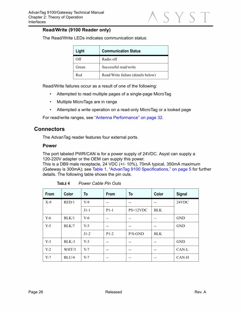
Read/Write (9100 Reader only)The Read/Write LEDs indicates communication status:
Read/Write failures occur as a result of one of the following:
• Attempted to read multiple pages of a single-page MicroTag
• Multiple MicroTags are in range
• Attempted a write operation on a read-only MicroTag or a looked page
For read/write ranges, see “Antenna Performance” on page 32.
ConnectorsThe AdvanTag reader features four external ports.
PowerThe port labeled PWR/CAN is for a power supply of 24VDC. Asyst can supply a 120-220V adapter or the OEM can supply this power.This is a DB9 male receptacle, 24 VDC (+/- 10%), 70mA typical, 350mA maximum (Gateway is 300mA); see Table 1, “AdvanTag 9100 Specifications,” on page 5 for further details. The following table shows the pin outs.
Light Communication Status
Off Radio off
Green Successful read/write
Red Read/Write failure (details below)
TABLE 4 Power Cable Pin Outs
From Color To From To Color Signal
X-9 RED/1 Y-9 -- -- -- 24VDC
J1-1 P1-1 PS+12VDC BLK
Y-6 BLK/1 V-6 -- -- -- GND
Y-5 BLK/7 Y-5 -- -- -- GND
J1-2 P1-2 P/S-GND BLK
Y-3 BLK-3 Y-3 -- -- -- GND
Y-2 WHT/3 Y-7 -- -- -- CAN-L
Y-7 BLU/4 Y-7 -- -- -- CAN-H
Page 26 Released Rev. A

AdvanTag 9100/Gateway Technical ManualChapter 2: Theory of Operation
Interfacesa
CommunicationThe port labeled RS232 COMM is for RS232 communication.This is a shielded RJ45 socket. A cable which connects the Reader to a PC is available from Asyst.SHOCK HAZARD
CAUTION
DO NOT TOUCH THE INSIDE OF THE ANTENNA CONNECTOR. FAILURE TO COMPLY MAY RESULT IN INJURY.
Antenna
CAUTIONANTENNAS SHOULD ONLY BE INSTALLED BY QUALIFIED PERSONNEL. FAILURE TO COMPLY MAY RESULT IN MALFUNCTION OR DAMAGE TO THE UNIT AND/OR ANTENNA.
The port labeled REMOTE ANTENNA is for an external antenna. Contact Asyst for available antennas.This is a BNC socket; use with Asyst antennas is required.
GENERAL HAZARD
CAUTION
NEVER USE A NON-ASYST ANTENNA WITH THE ADVANTAG 9100. FAILURE TO COMPLY WILL VOID FCC AND CE CERTIFICATION.
Pin Signal
4 Ground
5 Tx Data
6 Rx Data
Rev. A Released Page 27

AdvanTag 9100/Gateway Technical ManualChapter 2: Theory of OperationInterfaces a
External Presence (9100 Reader only)The port labeled REMOTE I/O is for an external presence sensor that detects events such as pod arrival and pod removal.The REMOTE I/O port is a shielded RJ45 socket used for the external presence sensor.
Ethernet (in development)The Ethernet port is a shielded RJ45 socket used for communication to a host using HSMS.
NOTE . . .
FOR INFORMATION ON COMMUNICATION THROUGH ALL PORTS, PLEASE REFER TO THE SOFTWARE MANUAL.
Buttons/SwitchesResetPress this button to reset the unit. This will set the baud rate to 9600 and the SECS DeviceID to match the TargetID (default is 0003).
Code UpgradeIt will be necessary to put the AdvanTag in Upgrade mode in order to download new software through the serial port.
To set the AdvanTag 9100 in Upgrade mode, press the Reset and Code Upgrade buttons simultaneously, then release the Reset button, then wait approximately 2-3 seconds, then release the Code Upgrade button.
To exit Upgrade mode, press the Reset button.
Pin Signal
1 24 VDC
2 Presence
4 Ground
Pin Signal
1 TX+
2 TX-
3 RX+
6 RX-
Page 28 Released Rev. A

AdvanTag 9100/Gateway Technical ManualChapter 2: Theory of Operation
Interfacesa
Long Range (9100 Reader only)Located on the side of the unit (see Figure 8 on page 29), this dip switch controls the read/write range of the antenna. When the switch is in the On position, the unit is in Standard Range mode. When the switch is in the Off Position, the unit is in Long Range mode (see “Antenna Performance” on page 32).FIGURE 8 Long Range Switch, AdvanTag 9100 Reader, Side View
Node Address (9100 Reader only)
CAUTIONTHE NODE ADDRESS PANEL (SEE Figure 9 on page 30) SHOULD ONLY BE ACCESSED BY QUALIFIED PERSONNEL. FAILURE TO COMPLY MAY RESULT IN MALFUNCTION OR DAMAGE TO THE UNIT.
Used to specify the unit's address or TargetID. The switches represent powers of binary digits:
The ON setting represents 1 and the OFF setting represents 0. For example, to set the address to “15,” set switches 1, 2, 3, 4 ON and 5, 6 OFF. See Figure 9 on page 30.
Switch # Binary Digit
1 1
2 2
3 4
4 8
5 16
6 32
Antenna Connector
CAN PWR Connector
Long Range Switch
Rev. A Released Page 29

AdvanTag 9100/Gateway Technical ManualChapter 2: Theory of OperationInterfaces a
FIGURE 9 Node Address Switches (9100 Reader only)
CommunicationsTo HostThe AdvanTag reader communicates to the host via RS-232, CAN, or LAN ports.
Read RangeTypical read range of the AdvanTag reader is 1 to 4 inches (1 to 7 inches in Long Range mode). Read range is dependent on the antenna design and the operational environment in which the antenna is installed. See “Antenna Performance” on page 32 for further details.
SECS/ASCIIRefer to the specific protocol documentation concerning either Stream 18 SECS messages or Asyst ASCII messages for details. The basic functions available are to read and write attributes, read and write material IDs (MIDs), read and write data, and various subsystem commands such as turning an LED on or off. Note that the single-page transponders hold an 8 byte MID only and the multi-page transponders hold a 16-byte MID and 120 bytes of data.
The TargetID (as described in the SEMI E99 and E5 standards) can be set with the NODE ADDRESS switches; default value is 3. The SECS I DeviceID can be set through an attribute or the Reset button. When Reset, the DeviceID is automatically changed to match the TargetID; the baud rate will be changed to the default 9600 as well. The baud rate can also be set through an attribute setting. Byte format is 8 data bits, 1 stop bit and no parity. The SECS I timeouts and retries can be set through attribute settings; defaults are T1 = 0.5 secs, T2 = 10 secs, T3 = 45 secs, T4 = 45 secs, Retries = 3.
When connected on CANbus, no two AdvanTag 9100s should have the same Target ID.
Page 30 Released Rev. A
AdvanTag 9100/Gateway Technical ManualChapter 2: Theory of Operation
Interfacesa
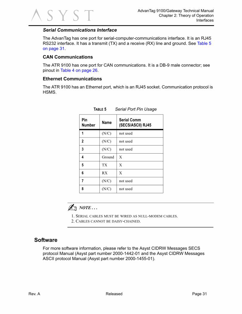
Serial Communications InterfaceThe AdvanTag has one port for serial-computer-communications interface. It is an RJ45 RS232 interface. It has a transmit (TX) and a receive (RX) line and ground. See Table 5 on page 31.CAN CommunicationsThe ATR 9100 has one port for CAN communications. It is a DB-9 male connector; see pinout in Table 4 on page 26.
Ethernet CommunicationsThe ATR 9100 has an Ethernet port, which is an RJ45 socket. Communication protocol is HSMS.
NOTE . . .
1. SERIAL CABLES MUST BE WIRED AS NULL-MODEM CABLES.2. CABLES CANNOT BE DAISY-CHAINED.
SoftwareFor more software information, please refer to the Asyst CIDRW Messages SECS protocol Manual (Asyst part number 2000-1442-01 and the Asyst CIDRW Messages ASCII protocol Manual (Asyst part number 2000-1455-01).
TABLE 5 Serial Port Pin Usage
PinNumber Name Serial Comm
(SECS/ASCII) RJ45
1 (N/C) not used
2 (N/C) not used
3 (N/C) not used
4 Ground X
5 TX X
6 RX X
7 (N/C) not used
8 (N/C) not used
Rev. A Released Page 31

AdvanTag 9100/Gateway Technical ManualChapter 2: Theory of OperationInterfaces a
Antenna PerformanceThe AdvanTag antennas work in conjunction with the AdvanTag Reader ATR9100 to read and write the MicroTag. Communications occur between the antenna and the MicroTag using very low radio frequency (134.2khz). Performance of these antennas (read and write distance as well as speed) is affected by the presence of metal and RF generators, such as color monitors in the antenna communication field.
Read/Write Performance FactorsFactors that influence tag read and write performance:
• Proximity of the tag and antenna
• Length of cable between the AdvanTag Reader and the antenna (including exten-sion cables)
• Orientation of the tag to the antenna
• Amount of metal adjacent to either the tag or the antenna
• Amount of background EMF in the environment
NOTE . . .
IF AN ANTENNA IS POSITIONED AGAINST A MICROTAG, THE ANTENNA WILL NOT READ IN MOST CASES. ALL OF THE RESULTS LISTED WERE TESTED IN AN OFFICE ENVIRONMENT.
RF Field Diagrams (9100 Reader only)The diagrams accompanying the types of antenna for reference only. Note the following conditions for each diagram:
• The coil of micro-tag must be completely contained in write area.
• The shaded area in center is a non-write area (null).
• Write ranges are approximately 50% of read ranges.
• The read and write distances cited are for reference only. Ranges are dependent upon actual installed environment.
• It may not be possible to replicate the same results outside of lab environments due to a variety of environmental conditions.
Stick AntennasThe stick antenna 9700-9097-01 is designed to be attached to the external antenna connector of the ATR 9100 and optimized for use in metallic environments such as a 300mm Front-Load (PN 9700-6224-02). The average read range is 2.0" (50.8mm). These stick antenna diagrams refer to a stick antenna as being flat on the YZ axis, centered at 0,0,0.
Page 32 Released Rev. A

AdvanTag 9100/Gateway Technical ManualChapter 2: Theory of Operation
Interfacesa
FIGURE 10 Stick Antenna 9700-9097-01 (Standard Range only)
Rev. A Released Page 33

AdvanTag 9100/Gateway Technical ManualChapter 2: Theory of OperationInterfaces a
Page 34 Released Rev. A

a
Chapter 3: TroubleshootingThis chapter presents the common problems that may occur when using the AdvanTag unit.
Troubleshooting ChartIf there are any other problems, or if none of the above corrective actions clears the problem, replace the AdvanTag.
If there are any other problems, or if none of the above corrective actions clears the problem, replace the AdvanTag. Other considerations to assure proper ATR functioning:
• The baud rate is to be the same between Host and ATR.
• The target ID is to be correct in the SECS and ASCII message that gets sent to the ATR.
• The MicroTag is to be in the proper range and relative location to the antenna.
TABLE 6 ATR Errors and Solutions
Error or Symptom Likely Cause(s) Corrective Action
Unit not functioning properly.
Power failure. Check connection for power cables.Is the power LED on? It must be green.Note: Host Comm, Read/Write LEDs—each to blink for approximately 2 seconds total at green, orange, then red before they turn off.
Communication cables loose or disconnected.
Check serial cables for loose connector.Check connector for bent pin(s).
During read and write programs, the READ/WRITE LED turns red.
MicroTag or antenna is not installed correctly.
Install MicroTag correctly. The READ/WRITE LED should turn green only.Refer to ATR magnetic field pattern diagram.
During read and write programs, the READ/WRITE LED turns orange instead of green.
MicroTag is not present or out of range.The antenna cable is loose.The antenna is bad.
Install MicroTag or antenna properly. The READ/WRITE LED should turn green.Tighten the antenna cable.Replace the antenna.Adjust the location of the antenna.
During read and write programs, the READ/WRITE LED does not blink.
The RS232 cable is loose.The RS232 cable is bad.The ATR is bad.Host command is wrong.
Tighten the RS232 cable.Replace the RS232 cable.Replace the ATR.Check Host command and target ID.
Rev. A Released Page 35

AdvanTag 9100/Gateway Technical ManualTroubleshooting Chart a
Page 36 Released Rev. A

Rev. A Released Page 37
AdvanTag 9100/Gateway Technical Manual
aAantennas
stick 32tubular 32
audience 1
Bbaud rates 16binary digits 29
Ccomments, reader iiconventions 1
Ddefault settings 16, 28deviceID 30disclaimers i
Eequipment modification i
HHost Comm LED 25
Iinstallation kit, 300mm Front-Load 17
Llanguages i
MMicroTag 32
Nnode address 29
Ooperating program 11outline drawing 5
Ppower indicator 25
Rranges
readtypical 30
read/write performance factors 32references 1reset 28
SSEMI safety standards 11specifications 5
TtargetID 30theory of operation 11trademarks itraining i


![Dion[1] 9100](https://static.fdocuments.us/doc/165x107/5549052eb4c90565458b4d76/dion1-9100.jpg)