Advances in Portable Ultrasonic Test Equipment - AREMA · ABSTRACT Portable ultrasonic equipment is...
30
Advances in Portable Ultrasonic Test Equipment Markus Nottelmann Sperry Rail Service 46 Shelter Rock Road, Danbury, CT 06810 Office: +1 (203) 791-4526 Fax: +1 (203) 791-4512 MS-Word Word Count: 2,551 Number of Pictures: 10 @ 250 words per picture = 2,500 words Total Word Count: 5,051 © 2011 AREMA ®
Transcript of Advances in Portable Ultrasonic Test Equipment - AREMA · ABSTRACT Portable ultrasonic equipment is...
Advances in Portable Ultrasonic Test Equipment
Markus Nottelmann
Sperry Rail Service
46 Shelter Rock Road, Danbury, CT 06810
Office: +1 (203) 791-4526
Fax: +1 (203) 791-4512
MS-Word Word Count: 2,551
Number of Pictures: 10 @ 250 words per picture = 2,500 words
Total Word Count: 5,051
© 2011 AREMA ®

Contents
Abstract
Historical context
Basic Walking Stick Technology
Introduction of B-Scan Technology
Integrated GPS
B-Scan Display
Comprehensive Roller Search Units
Standard Probe Configuration
Alternative RSUs: VSH and X-Fire
Built-In Reporting System
Built-in Connectivity
The Final Product
Dual Rail Inspection Systems
Motorized portable Equipment
Optimising the Deployment of rail Testing Technology
Conclusion
Listing of Figure Captions
© 2011 AREMA ®

ABSTRACT
Portable ultrasonic equipment is being used extensively today for a variety of important rail
testing applications. While hi-rail and rail-bound test vehicles are often the most efficient tool for
mainline rail flaw detection needs, some applications, including the testing of yards, switches,
crossings, replacement rail and verification behind regular test vehicles benefit from the
efficiency of pedestrian or manually operated testing equipment. Traditionally, this has been in
the form of A-scan based equipment such as walking sticks. Proficient ultrasonic operators have
been conducting effective real-time inspections for years with this type of equipment. However,
this process has some significant shortcomings including the absence of an auditable
permanent record of test, the lack of a ‘breadcrumb’ trail to document tested track, and
cumbersome activity and defect reporting.
New portable B-Scan solutions overcome these shortcomings by offering the same or improved
ultrasonic and ergonomic benefits, and by allowing offline analysis and full scale audit programs
customary with vehicle-based rail flaw detection programs improve the overall quality of rail flaw
detection programs. Built-in GPS systems allow accurate location and tested segment reporting.
User-friendly, built-in reporting systems, coupled with built-in connectivity systems including 3G
SIM cards and Wi-Fi connections, allow tying data to track maps and integrating reporting into
asset management tools. As a result, B-Scan Flaw Detector-based walking sticks and Dual Rail
Inspection Systems are quickly gaining acceptance by railroads.
© 2011 AREMA ®

HISTORICAL CONTEXT
Ultrasonic test systems used in hi-rail and railbound vehicles have seen significant
advancement over the last 10 years.
Development effort has focused on:
Increasing the speed of testing up to 80kph to reduce track occupancy
Improved auditability of the test system and the data collected
Improved location, with defects being uniquely tagged by accurate GPS
Improved analysis with the use of B-Scan views which present a GUI to the analyst
showing an intuitive representation of the defect within the rail
Improved run-on-run comparison of test data based on a the accurate location and B-
Scan presentation
As these developments have matured it has been natural for customers and test engineers to
seek similar capabilities in portable ultrasonic equipment.
This paper discusses the recent advances which have been made in portable ultrasonic
equipment and the benefits to be gained.
© 2011 AREMA ®
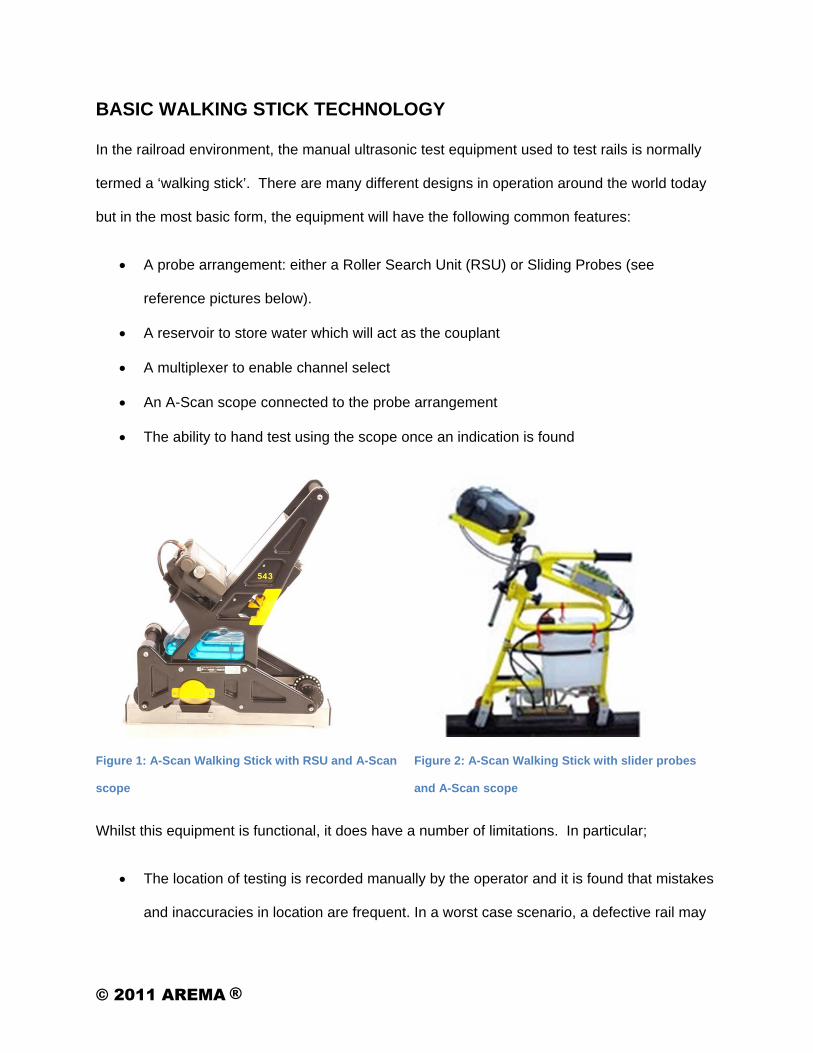
BASIC WALKING STICK TECHNOLOGY
In the railroad environment, the manual ultrasonic test equipment used to test rails is normally
termed a ‘walking stick’. There are many different designs in operation around the world today
but in the most basic form, the equipment will have the following common features:
A probe arrangement: either a Roller Search Unit (RSU) or Sliding Probes (see
reference pictures below).
A reservoir to store water which will act as the couplant
A multiplexer to enable channel select
An A-Scan scope connected to the probe arrangement
The ability to hand test using the scope once an indication is found
Figure 1: A-Scan Walking Stick with RSU and A-Scan
scope
Figure 2: A-Scan Walking Stick with slider probes
and A-Scan scope
Whilst this equipment is functional, it does have a number of limitations. In particular;
The location of testing is recorded manually by the operator and it is found that mistakes
and inaccuracies in location are frequent. In a worst case scenario, a defective rail may
© 2011 AREMA ®
be mistakenly left in service after having been incorrectly identified as tested, leading to
a service failure or derailment.
Rail managers have no independent means of checking that the rail has been tested by
the operator. In extreme circumstance fabrication of test records by operators has been
documented.
Some equipment is only uni-directional, so bi-directional track often requires two tests.
There is no permanent record of what the operator finds, i.e. the A-Scan is not normally
recorded.
Information required at a defect (such as location, defect classification, rail type and age)
is normally written on to paper which has to be then separately entered into computer
systems by clerks. This two-stage data entry leads to a significant number of
transcription errors, reducing the usefulness of the information collected.
Because of the poor location information, data is very difficult to accurately cross-
correlate with other information, such as track curvature, track geometry defects etc.
The walking stick requires an operator with a high level of ultrasonic competence to
interpret the A –Scans.
INTRODUCTION OF B-SCAN TECHNOLOGY
Continuing developments in the computer industry, specifically the reduction in size of computer
hardware, the decrease in power requirements, and the increase in processing power have
allowed the creation of small yet powerful computers for rail flaw detection purposes.
Components carefully selected to provide continuous and reliable service in railroads’ harsh
environments have provided the basis for testing equipment to be used for a variety of
purposes. In the following sections each of the developments recently built in to the new
© 2011 AREMA ®

generation of Portable Ultrasonic Test Equipment will be explained along with their resulting
benefits.
Integrated GPS
The integration of GPS into the walking stick brings multiple benefits. First, it enables a
‘breadcrumb’ trail to be produced showing the exact starting and ending mile points of rail
tested. This is an auditable record that the Rail Manager can use to assure himself that the rail
has been correctly tested by the operator.
Figure 3: Example of GPS Plot from of two rails in a curve tested with a B-Scan walking stick.
Second it defines the location of a defect in a way that traditional railway location (i.e.
Miles/Yardage or Kilometres/Metres) cannot match, permitting subsequent querying of the
captured datasets by GIS databases and cross-correlation with other sources.
B-Scan Display
The addition of the B-Scan display is a significant advancement in walking stick technology.
The walking stick is now no longer limited to displaying only a single ultrasonic channel as the
operator tests. Instead, the multiplexor gathers the data from all the ultrasonic probes as the
walking stick is pushed along the rail and the signals are automatically analysed by the test
system software. The test system synthesizes the complex signals and displays an intuitive
© 2011 AREMA ®

presentation to the operator. Once an indication of interest is displayed on the screen the
operator can stop, and, if necessary, re-run an area with the walking stick or investigate the rail
further using the A-scan mode to comprehensively size the defect.
Comprehensive Roller Search Units
The addition of a range of powerful RSU configurations gives increasing power to the walking
stick. Common RSU configurations include the UX-9, VSH and angled probe RSUs. A variety
of plug-and-play RSUs allows for the deployment of RSUs appropriate for specific tasks or
requirements.
Standard Probe Configuration
For example, a standard RSU may contain nine probes in the following configuration:
One 0° probe to inspect the head and web
Two 45° degree probes in the forward and reverse directions for web and bolt hole
inspection
Six 70° degree probes covering the entire head in the forward and reverse directions
This arrangement, for example, gives not only full head coverage but also bi-directional
operation which significantly improves productivity.
Alternative RSUs: VSH and X-Fire
Special applications sometimes call for task-specific probe arrangements. Two such probe
arrangements are Vertical Split Head RSUs and obliquely-angled transducer arrays designed to
detect defects obscured by surface conditions such as head checking or shelling.
Built-In Reporting System
Activity and Defect Reporting Systems are customary in hi-rail and railbound rail flaw detection
vehicles, where the activity and defect reporting system is often tightly integrated with the actual
© 2011 AREMA ®

test system to reduce the requirement for operator entry and to ensure data integrity. In A-scan-
based pedestrian equipment activity and defect reporting is often completed after a test which
can lead to incomplete or inaccurate reporting.
As B-Scan-based pedestrian equipment is built on standard computer hardware running
standard operating systems such as Windows or Windows CE, the integration of user-friendly,
touchscreen-based activity reporting systems considered standard in vehicle operations can be
effectively integrated into the pedestrian equipment. Relevant data generated by the test system
is automatically transferred to activity and defect reports. This results in complete and more
accurate information. The Rail Manager is then enabled to report on walking stick activity in the
same manner as he is used to in vehicle operations, and by extension, plan walking stick testing
more effectively.
Figure 4: Example of B-Scan display and a
touchscreen-based data entry system
Figure 5: Example of an integrated activity and
defect reporting system
© 2011 AREMA ®

Built-in Connectivity
In order to provide direct connectivity to rail defect data management systems, for example the
Sperry Data Management System (SDMS), SIM-card based cellular access capability has been
provided. While most B-Scan walking sticks provide USB ports to connect standard USB sticks
to transfer data, the availability of cellular access reduces the workload on the operator after the
end of a work shift to transfer data. Cellular access also allows for the real-time transmission of
data for immediate remote evaluation, or instantaneous peer review. The significance of this
development in terms of improved data quality cannot be overstated. By providing the ability to
upload the B-Scan display the auditability of the test is once again improved and can be
compared directly to the results of either hi-rail or rail-bound testing.
© 2011 AREMA ®

THE FINAL PRODUCT
A comparison of an A-scan walking stick described earlier in this paper and a B-Scan walking
stick shown below clearly demonstrates the ability to integrate all of the B-Scan features into a
small enough package to still meet the same weight and ergonomic requirements of an A-Scan
walking stick package. Couplant capacity and battery life remain consistent with those of A-
Scan walking sticks, allowing the completion of a normal workday on a single battery charge
and one filled couplant tank, while providing all the additional benefits of B-Scan technology, i.e.
an auditable permanent record of test, user-friendly B-Scan presentation, integrated GPS,
wireless connectivity, and an integrated activity and defect reporting system.
Figure 6: B-Scan Walking Stick with integrated GPS and activity and defect reporting system
© 2011 AREMA ®

DUAL RAIL INSPECTION SYSTEMS
While walking sticks, whether B-Scan or A-Scan, play clearly defined roles in the world of rail
testing, such as cross-over and plug rail inspections, there are other applications in which the
inspections of both rails in a track concurrently is more efficient. While some railroads
accomplish this by running two walking sticks side-by-side under watchman/lookout protection,
for longer stretches of track, for example yard tracks, a dual rail inspection system is more
efficient.
This application was taken into account during the development of B-Scan computer
technology. Linked B-Scan units enable the running of Dual Rail Inspection Systems (DRIS) that
operate, in effect, as a small test vehicle. DRIS units offer all the benefits of a single rail walking
stick while maintaining battery and couplant capacity for a full shift, but also provide additional
benefits such as easy adjustment for a variety of gauges, and basic track geometry
measurements. DRIS units are sufficiently portable to allow testing of both rails simultaneously
by one operator.
Figure 7: B-Scan Dual Rail Inspection System with
integrated GPS, wireless connectivity and activity
and defect reporting system
Figure 8: A-Scan Dual Rail Inspection System with
slider probes
© 2011 AREMA ®

MOTORIZED PORTABLE EQUIPMENT
Certain railroad environments, for example captive or remote railroads that are too large for
pedestrian operations but too small or inaccessible to warrant hi-rail or railbound equipment,
have a demonstrated need for a form of motorized rail flaw detection equipment. DRIS units,
coupled with electric trolleys, enable rail testing at up to 10mph, providing a significant increase
in productivity over pedestrian-operated equipment. To maintain portability, the various
components of the motorized trolley can usually be assembled or disassembled by two people
in five minutes or less, allowing for easy transportation, setup and storage.
Figure 9: Motorized B-Scan trolleys are adapted to
meet all specific local safety requirements
Figure 10: Motorized B-Scan Trolley in operation on
a captive narrow gauge system
© 2011 AREMA ®

OPTIMISING THE DEPLOYMENT OF RAIL TESTING TECHNOLOGY
Whilst there is no doubt that hi-rail and rail-bound platforms are the most efficient for testing
mainline rail, pedestrian equipment is the optimum technology for many other situations.
For short sections of rail, cross-overs and replacement rail walking sticks are generally
most efficient.
For yard tracks and industrial spurs, the deployment of a DRIS unit is often more
economic than the deployment of a hi-rail vehicle.
Captive systems that are too small to warrant the deployment of a hi-rail or railbound
vehicle but too large to be covered effectively with pedestrian-operated equipment can
benefit from motorized B-Scan Trolley applications.
As with all rail testing services, each railroad needs to carefully consider a cost-benefit analysis
for each of these applications. To provide the highest return on investment these solutions need
to fit into the track operator’s overall rail testing program, including required testing frequencies.
Many rail operators have found that the best way to take advantage of all the features offered by
new B-Scan-based pedestrian equipment is to utilize the services of traditional rail flaw
detection service providers that have a pool of trained and certified staff to respond to needs
and requirements on an as-needed basis. This ensures integration and consistency with
existing rail testing programs, including audit schedules, quality reviews, and reporting solutions
that are generally in place.
© 2011 AREMA ®

CONCLUSION
Pedestrian rail flaw detection equipment has been effectively used for many years in specialized
testing applications where the deployment of traditional hi-rail or railbound equipment would be
inappropriate or not cost effective. The introduction of B-Scan technology in the pedestrian
testing equipment world brings the traditional benefits of vehicular rail testing, including an
auditable permanent record of test, integrated GPS breadcrumb trail, and integrated activity and
defect reporting to these special applications. This provides significantly improved quality in
special testing applications allows the track operator to fully integrate pedestrian equipment-
based special testing applications with the full rail testing program.
© 2011 AREMA ®

LISTING OF FIGURE CAPTIONS
Figure 1: A-Scan Walking Stick with RSU and A-Scan scope
Figure 2: A-Scan Walking Stick with slider probes and A-Scan scope
Figure 3: Example of GPS Plot from of two rails in a curve tested with a B-Scan walking stick.
Figure 4: Example of B-Scan display and a touchscreen-based data entry system
Figure 5: Example of an integrated activity and defect reporting system
Figure 6: B-Scan Walking Stick with integrated GPS and activity and defect reporting system
Figure 7: B-Scan Dual Rail Inspection System with integrated GPS, wireless connectivity and
activity and defect reporting system
Figure 8: A-Scan Dual Rail Inspection System with slider probes
Figure 9: Motorized B-Scan trolleys are adapted to meet all specific local safety requirements
Figure 10: Motorized B-Scan Trolley in operation on a captive narrow gauge system
© 2011 AREMA ®

2011 ANNUAL CONFERENCESeptember 18-21, 2011 | Minneapolis, MN
Markus NottelmannCommercial DirectorSperry Rail Service

2011 ANNUAL CONFERENCESeptember 18-21, 2011 | Minneapolis, MN
• Inspection of railroad track for internal flaws
• Goal is to maximize productivity and safety, and help eliminate risk of service failures and derailments
• Technique first developed by Sperry in 1928

2011 ANNUAL CONFERENCESeptember 18-21, 2011 | Minneapolis, MN
Rail is inspected using specialized test vehicles and equipment
• Railbound vehicles

2011 ANNUAL CONFERENCESeptember 18-21, 2011 | Minneapolis, MN
Rail is inspected using specialized test vehicles and equipment• Hi-rail vehicles

2011 ANNUAL CONFERENCESeptember 18-21, 2011 | Minneapolis, MN
Rail is inspected using specialized test vehicles and equipment• Portable testing equipment

2011 ANNUAL CONFERENCESeptember 18-21, 2011 | Minneapolis, MN
Rail is inspected using specialized test vehicles and equipment• Hand test equipment

2011 ANNUAL CONFERENCESeptember 18-21, 2011 | Minneapolis, MN
• Single-operator walking sticks use Roller Search Units (RSUs) to conduct ultrasonic testing of the rail
• Special Applications• Mainline track, where
appropriate• Yards• Crossings• Points/switches• Replacement rail• Verification work after vehicle
testing
2011 ANNUAL CONFERENCESeptember 18-21, 2011 | Minneapolis, MN
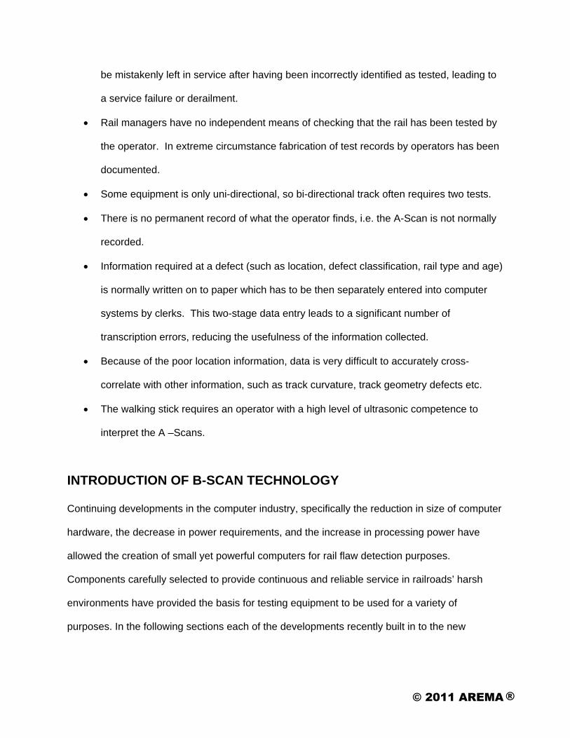
A-Scan Equipment• Requires a high degree of
operator proficiency• Often slider probe-based
resulting in high water usage
• No auditable permanent record of test
• Were the right settings used?• What rail/track was tested?
• Lack of a breadcrumb trail to document tested track
• Cumbersome activity and defect reporting
Krautkramer SPG 3

2011 ANNUAL CONFERENCESeptember 18-21, 2011 | Minneapolis, MN
Overcomes limitations of traditional portable RFD equipment:• Roller Search Unit (RSU) based
• Lower water usage• RSU conforms to rail maintaining the
UT signal for higher defect-detection ratios
• More compact and light weight• Fully auditable record of test
• Stores miles and miles of test data and settings
• GPS breadcrumb trail• Accurate location and tested segment
reporting
• Multiple Languages

2011 ANNUAL CONFERENCESeptember 18-21, 2011 | Minneapolis, MN
Overcomes limitations of traditional portable RFD equipment (cont.):
• Built-in connectivity • Ties data to track maps• Integrates reporting into asset
management tools
• Compatible with 3G Sim cards and WiFi connections
• Instantaneous uploads possible
• USB interface• Ethernet connection• Provides offline analysis/auditing
anywhere
2011 ANNUAL CONFERENCESeptember 18-21, 2011 | Minneapolis, MN
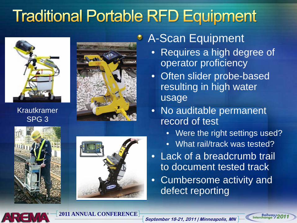
B-Scan Single Rail Walking Stick
• Single-operator portable device
• Provides fully auditable test record
• Comprehensive position tracking via built-in GPS
• Multi-channel display

2011 ANNUAL CONFERENCESeptember 18-21, 2011 | Minneapolis, MN
B-Scan Dual Rail Inspection System• Same benefits as single rail B-Scan Walking
Stick, but tests two rails at once with a single operator

2011 ANNUAL CONFERENCESeptember 18-21, 2011 | Minneapolis, MN
• B-Scan Dual Rail Inspection System can be attached to a powered track trolley
• Increases the amount of track tested per shift
2011 ANNUAL CONFERENCESeptember 18-21, 2011 | Minneapolis, MN
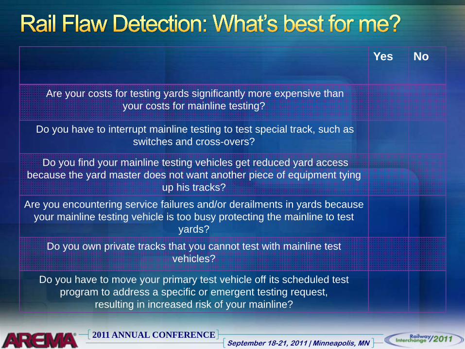
Yes No
Are your costs for testing yards significantly more expensive than your costs for mainline testing?
Do you have to interrupt mainline testing to test special track, such as switches and cross-overs?
Do you find your mainline testing vehicles get reduced yard access because the yard master does not want another piece of equipment tying
up his tracks?
Are you encountering service failures and/or derailments in yards because your mainline testing vehicle is too busy protecting the mainline to test
yards?
Do you own private tracks that you cannot test with mainline test vehicles?
Do you have to move your primary test vehicle off its scheduled test program to address a specific or emergent testing request,
resulting in increased risk of your mainline?