ADVANCES IN INORGANIC FIBRE TECHNOLOGY - dtic. · PDF fileADVANCES IN INORGANIC FIBRE...
103
AD-A260 79- ~ ~ 37/.- INTERNATIONAL WORKSHOP ON ADVANCES IN INORGANIC FIBRE TECHNOLOGY 13-14 August 1992 Clunies Ross House, 191 Royal Parade, Parkville Melbourne, Australia EXTENDED ABSTRACTS DTIC S FEB 18 1993 U E Jointly Organised by Sydney University Centre for Advanced Materials Technology CSIRO Division of Materials Science and Technology DSTO Materials Research Laboratory N - Australian Ceramic Society 0- Supported by ' US Army Research Office (LABCOM) - Far East Defence Advanced Research Projects Agency/DSO Department of Industry, Technology and Commerce (DITAC) ASTRIBlJ,.N STATEM-' S , .. • Approved f r pulc M 2. 1elOS
Transcript of ADVANCES IN INORGANIC FIBRE TECHNOLOGY - dtic. · PDF fileADVANCES IN INORGANIC FIBRE...

AD-A260 79- ~ ~ 37/.-
INTERNATIONAL WORKSHOP
ON
ADVANCES IN INORGANIC FIBRE TECHNOLOGY
13-14 August 1992Clunies Ross House, 191 Royal Parade, Parkville
Melbourne, Australia
EXTENDED ABSTRACTS
DTICSELECTE
FEB 18 1993
U EJointly Organised by
Sydney University Centre for Advanced Materials TechnologyCSIRO Division of Materials Science and Technology
DSTO Materials Research Laboratory N -
Australian Ceramic Society
0-Supported by '
US Army Research Office (LABCOM) - Far EastDefence Advanced Research Projects Agency/DSO
Department of Industry, Technology and Commerce (DITAC)
ASTRIBlJ,.N STATEM-' S , ..•
Approved f r pulc M 2. 1elOS

DISCLAIMEI NOTICE
THIS DOCUMENT IS BESTQUALITY AVAILABLE. THE COPY
FURNISHED TO DTIC CONTAINED
A SIGNIFICANT NUMBER OF
PAGES WHICH DO NOTREPRODUCE LEGIBLY.

MASTER COPY KEEP THIS COPY FOR REPRODUCTION PURPoSES
REPOT D CUM NTATON AGEForm Approved
REPORT~~~ DOU ETTINPG MB No 0704-0188P~bit,c 'eoc"-riq o~der ior t, Collecton of n~Cfolatori is estimated to a~erage i our per rewOrse ncRdrnq ithe it-r~ for ev-ew nq t~cO serc'"~ exst~nq cata souree
Jiuin 92i prinipa investigator)l 9
4. PITERRMNG ORU AIBAIONE NAESSN ORS(S. PEFORMING OUBRGAIATO
7. SPONSORMING MORGNIZTIORNGANY NAME(S) AND ADDRESS ES 10. SPONSORMING MORGNIZTIORNGAGNYREPORT NUMBER
U. S. Army Research Office AEC EOTNME
P. 0. Box 12211
Research Triangle Park, NC 27709-2211 ARC 30744.1-MS-CF
11. SUPPLEMENTARY NOTES
The view, opinions and/or findings contained in this report are those of theauthor(s) and should not be construed as an official Department of the Armyposition, policy, or decision, unless so designated by other documentation.
12a DISTRIBUTION A VAILABILITY STATEMENT 12.DISTRIBUTION CODE
Approved for public release; distribution unlimited.
13. ABSTRACT (Maximum 200 words)
The workshop was held as scheduled and extended abstrdcts of the presentationshave been published.
14. SUBJECT TERMS Glass Fibers, 15. NUMBER OF PAGES
workshop, Inorganic Fiber Technology, 95Fiber Technology, Silicon Carbide Fibers, 16. PRICE CODECeramic Matrix Composites Carbon Fibers,
17. SECURITY CLASSIFICATION 18. SECURITY CLASSIFICATION 19. SECURITY CLASSIFICATION 20. LIMITATION OF ABSTRACTOF REPORT OF THIS PAGE OF ABSTRACT
UNCLASSIFIED I UNCLASSIFIED I UNCLASSIFIED ULNS 7540-01-280-5500 Starndar Form 298 ýRev 2 89.
P'i h, b~AN%i iird 119.'8
EXTENDED ABSTRACTS OF THE INTERNATIONAL WORKSHOP
ON
ADVANCES IN INORGANIC FIBRE TECHNOLOGY
Edited by
Yiu-Wing MaiCentre for Advanced Materials Technology
University of SydneyAcct:sio;', 'or
July 1992 f Th'v
By
Di tA, ,;. ,i C-"e
Organising Committee 1 ,
DT1,- QUA,11 •-1 . -77 :Professor Yiu-Wing Mai, Sydney University - ChairmanDr John Bannister, CSIRO Division of Materials Science & Technology, ClaytonDr Janis Cocking, DSTO Materials Research Laboratory, Maribyrnong

PROGRAM
Page
Thursday, 13 August 1992
0800- 0845 Registration
0845 - 0900 Opening AddressDr. Iqbal Ahmad, Associate Director, ARO - Far East
Session 1 Advances in Inorganic Fibres Technology I- Silicon Carbide Fibres
Chairpersons: Dr. Janis Cocking (DSTO MaterialsResearch Laboratory); Dr. Bill Sinclair (BHPMaterials Research Laboratory)
0900- 0940 Recent development of SiC fibres 'NICALON'and their composites including properties of SiCfibres 'HI-NICALON' for ultrahigh temperature(T. Ishikawa, Japan)
0940- 1020 Fine diameter polycrystalline SiC fibres 5(J. Lipowitz, T. Barnard, D. Bujalski, J. Rabe, G. Zank,A. Zangvil and Y. Xu, USA)
1020- 1100 Pyrolytic behaviour of polymer-derived SiC fibres 11(K. Okamura, J. Nishida, T. Shimoo, T. Seguchi andH. Ichikawa, Japan)
1100- 1130 Coffee and Tea Break
1130- 1210 Polymer-derived SiC fibres with improved 17thermomechanical stability(Wm. Toreki, G.J. Choi, C.D. Batich, M.D. Sacksand M. Saleem, USA)

Thursday, 13 August (Conid.)
1210 - 1250 New curing method for polycarbosilane with 22unsaturated hydrocarbons and application tothermally stable SiC fibre(Y. Hasegawa, Japan)
1250- 1400 Lunch
Session 2 Fibre-Matrix Interface Micromechanicsand Ceramic Matrix Composites
Chairpersons: Professor Yiu-Wing Mai (University of Sydney);Dr. Sri Lathabai (CSIRO Division of Materials Science& Technology)
1400- 1440 Interfacial control and macroscopic failure in 30inorganic composites(T.W. Clyne and A.J. Phillipps, UK)
1440- 1510 The role of fibre/matrix interface in the first matrix 37cracking of fibre-reinforced brittle matrix composites(T. Suzuki and M. Sakai, Japan)
1510- 1550 Issues in the control of fibre-matrix interface 42properties in ceramic composites(R.I. Kerans, USA)
1550- 1620 Coffee and Tea Break
1620- 1700 Recent progress in the design of advanced high 44temperature composites(J. Economy, USA)
1700- 1740 Pressureless sintering of silicon nitride composites 46(T. Yonezawa, S. Saitoh, M. Minamizawaand T. Matsuda, Japan)
WORKSHOP DINNER

Friday, 14 August 1992
Session 3 Advances in Inorganic Fibres Technology II
Chairpersons: Dr. Alan Baker (DSTO AeronauticalResearch Laboratory); Dr. Besim Ben-Nissan (Universityof Technology, Sydney)
0830 - 0910 Inorganic fibres for composite materials 52(A.R. Bunsell, France)
0910- 0950 Inorganic fibres directly from the vapour phase 55(F.T. Wallenberger and P.C. Nordine, USA)
0950- 1030 High performance boron nitride fibres from 61poly(borazine) preceramics(Y. Kimura, Y. Kubo and N. Hayashi, Japan)
1030- 1100 Coffee and Tea Break
1100- 1140 Simplified dynamic finite element processing model 66for the CVD of TiB2 fibres(R.J. Diefendorf and L. Mazlout, USA)
1140- 1220 Creep-related limitations of current polycrystalline 67ceramic fibres(J.A. DiCarlo, USA)
1220- 1330 Lunch

Friday, 14 August (Contd.)
Session 4 Advances in Inorganic Fibres Technology III- Carbon and Glass Fibres
Chairpersons: Dr. Caroline Baillie (University of Sydney);Dr. S. Bandyopadhyay (University of New South Wales)
1330- 1410 Advances in the development of high performance 73carbon fibres from PAN fibres(O.P. Bahl, India)
1410- 1450 Siliconizing reaction of carbon fibres 80(S. Yamada, E. Yasuda, Y. Tanabe, T. Akatsuand M. Shibuya, Japan)
1450- 1520 Coffee and Tea Break
1520- 1600 The dual nature of vapour grown carbon fibres 84(H. Jaeger and T. Behrsir.g, Australia)
1600 - 1640 Glass fibres from high and low viscosity oxide melts 90(F.T. Wallenberger and S.D. Brown, USA)
1640 - 1740 PANEL DISCUSSION
(Professor Yiu-Wing Mai, ChairmanWorkshop Organising Committee)

"Recent Development on SiC fibers 'W,'CALON' and Their Composites - Including
Properties of SiC Fibers 'HI-NICALON' for Ultrahigh Temperature"
Toshikatsu Ishikawa
NIPPON CARBON CO., LTD.
2 - 6 - 1, Hatcho-bori, Chuo-ku, Tokyo, 104, Japan.
SiC fibers NICALON, produced by NIPPON CARBON CO., LTD., has been placed a high
value on excellent properties as a heat resistant material and reinforcements for polymer matrix
composites, metal matrix composites and ceramic matrix composites. NICALON has growting
uses as an advanced material.
NICALON has materialized one of my fundamental ideologies for .Alog', that is. "from
Organic to Inorganic".
Fig.1 shows the fabrication process on NICALON.
NICALON has been made from dimethyldichlorosilane of a raw material for silicone resin.
Dimethyldichlorosilane has been changed to polydimethylsilane and then synthesized
polycarbosilane having basic Si-C skeleton of an organic silicone compound. Polycarbosilane has
been spun, cured and py'Tolized. SiC fibers "NICALON" has ben fabricated by processing above.
The fundamental technology has been invented by Prof. S. Yajima et al. in 1975. We, NIPPON
CARBON, have made the contract on the patent license immediately and started to
industrialization based on my decision making, because the SiC fibers have fitted to my ideology.
In case of industrialization, the most difficulty was in spinning and curing for polycarbosilane
of ,he precursor. Polycarbosilane is belonged to oligomer having 1,000 ~ 2,000 in mean molecular
weight, against raw materials of synthetic fibers such as polymers of Nylon and polyester etc.
having 40,000 - 50,000 in mean moiecular weight. Consequently, spun fiber had very low tensile
strength of 5 MPa and broke easily at a touch with the hand. Long fiber could not obtain by the
heat treatment system of carbon fiber and Prof. S. Yajima also obtained only single filament
having less than I m in length.
NIPPON CARBON has developed the new method without a touch on spinning, drawing out,
curing and pyTolizing for the oligomer.
In addition, we have established the know-how for below-mentioned and developed the
industrial technology on mass-production for high-performance continuous fibers having more
than 1,000m in length.
(1) Designs on optimum quality for polycarbosilane and fabrication condition;
t!) Technologies on spinning, drawing out, handling for the brittle green fiber;
2 Technologies on heat-treatment and surface treatment for the brittle green fiber.

Thus, the fibers made from the oligomer, have been commercialized first in the world. At
present, NICALON has been fabricated by the facility having capabi!ity of I ton per month.
Table I shows the properties of commercialized NICALON now.
We have researched and developed also on various composites using NICALON in parallel
with improving on NICALON.
Polymer matrix composite(PMC) has been developed on the micro wave absorber and the
transmitter having light weight and high tensile strength(NICALON/epoxy resin composite).
Metal matrix composite(MMC) has been developed on the composite wire using NICALON as
the reinforcement and aluminum as the matrix(N1CALON/Al composite wire).
Ceramic matrix composite(CMC) has been developed on the composite, called"NICALOCERAMmI', using NICALON and SIC made from polycarbosilane by polymer
impregnation pyrolysis method(N1CALON/SiC composite). N1CALOCERAMTM has been put topractical use on rollers working in molten zinc for galvanized sheet iron. Ceramic matrix
composite reinforced with NICALON has higher fracture toughness as compared to monolithic
ceramics. The higher facture toughness has been verified on both NICALON/glass ceramic
composite and NICALON/SiC(CVI) composite which are expected the practical use for light
weight and heat resistant structural material at more than 1,100°C, because even super heat
resistant alloy is useless at that temperature.
In addition, we have developed and commercialized NICALON fiber coated with carbon (NL-
607) for CMC. NL-607 has been placed a high value on excellent effectiveness as a reinforcement.
NICALON has excellent properties, especially heat resistance of maximum working
temperature at 1,200°C, however the heat resistance has not satisfied still the demands frommaterials for an advanced airframe, an advanced engine and an advanced gas turbine.
NICALON has been consisted of Si-C-O ternary compound and contained 12c-\\t. of oxygen.
Oxygen in the fibers decompose and remove with form of CO gas at more than 1,300°Cand tensile
strength of the fibers decrease.
We have developed the new curing process using an electron beam irradiation in an oxygen-
free atmosphere, jointly with Japan Atomic Energy Research Institute, for improving the heat
resistance. Consequently, we have developed the SiC fibers "HI-NICALON" containing 0.5%-wt.
of reduced oxygen content (refer to Fig. I for the fabrication proces of SiC fibers).
Table 2 shows typical properties of HI-NICALON having low oxygen content. HI-NICALON
has same tesile strength and higher tensile modulus as compared to customary NICALON.1tI-NICALON keeps more than 2 GPa in tensile strength after 10 hours exposure at 1,500,C inargon atmosphere, however customary NICALON decreases sharply tensile strength after same
heat treatment. HI-NICALON keeps still more fibrous form and flexibility after 1 hour exposure at
2,000°C in argon atmosphere. Thus, HI-NICALON has excellent heat resistance highly which
customary NICALON could not realize. HI-NICALON/SiC composite (NICAROCERAM.-v') has
excellent heat resistance highly, because the composite has 300MPa in flexural strength after I

hour heat treatment at _)00'C in air. This also shows HI-NICALON has excellent compatibility
%kith ceramic matrix.At present, industrialization for HI-NICALON has been promoted and we plan to make
mass-production and place on sale starting 1995.We expect that HI-NICALON will contribute to early developing for space plane, high
temperature gas turbine and nuclear fusion reactor etc., based on increased heat resistance ofmaterials using HI-NICALON for high temperature.
MeIDimethyldichlorosilane cl-si-cl
I- MeDechlorination Me
Dimethylpolysilane si \Me ,n
Rearrangement Me, (Me
Polycarbosilane 3 s,-CH2
Spinning
Green Fiber
Electron BeamIrradiation Oxidation
Cured. Fiber
Pyrolysis Pyrolysis
Si-C Fiber Si-C-O Fiber
(Hi-NICALON) (NICALON)
Fig. 1 FABRICATION PROCESS OF SiC FIBERS

Table 1 Typical properties and applications of NICALONCeramic Grade HVR Grace LVR Grace Carbor Coatec'
NL-200 NL-400 NL-500 NL-6C7
Diameter GUm) 14/12 14 14 14
Numbers of filaments (fl/yarn) 250/500 250/500 500 50C
(g/1000m) 105/210 110/220 210 210
s le ste-gth (MPa) 3000 2800 3000 300C
Tens -: :-odulus (GPa! 200 180 220 220
Elongation (%; 14 1 6 1.4 1.4
Density (kg iM3
) 2550 2300 2500 2550
Specific resistrvit, (ohm-cm) 1o3-104 106-107 0,5-50 C 8
Co-effc~ent of thermal expansion
00 06Ký 31 - -
Soeo'f,0 neat iJi'kg.K), 1140 1142
Tnerea' co ýV c ,t,•t. i K ýmK 12 --
D0elect,.c coýsta'•t ia: 10 GHz, 9 6 5 20-30
AzoIhcatons Heat resistant materials PMC PMC CIMC
PMC MMC, CMC
(Preliminary Data)
Table 2 Typical Properties of the Low Oxygen SiC Fiber "HI-NICALON"
'NICAL©,!Ceramic Gradej
F>:. diameter W m) 14 (14)
Numbers of filaments (fil/yarn) 500 (500)
Tex (g/1000mi 200 (210)
Tensile strength (GPa) 2.8 (3.0)
Tensile modulus (GPa) 270 (2201
Elongation (OC) 1.0 (1.4)
Density (kg/m2) 2,740 (2,550)
Specific resistivity (ohm-cm) 1.4 (103-104)
Chemical composition
(wt. /) Si 63.7 (58)
C 35.8 (30)
0 0.5 (12)

5
FINE DIAMETER POLYCRYSTALLINE SIC FIBERS
J. Lipowitz, T. Barnard, D. Bu-alski, J. Rabe, G. ZankDow Corning Corporation
Midland, MI 48686U.S.A.
A. Zangvil, Y. XuMaterials Research Laboratory
University of IllinoisUrbana, IL 61301
U.S.A.
Introduction
Small diameter ceramic fibers, which are sufficiently flexible to permit veavingand knitting, provide many desirable properties for use in contlnucus-fibercerLmic matrix corrpoeites (CMC) intended for high temperature performanc- inoxidative and inert atmospheres (1). Such fibers are also useful in plastic anometal matrix composites. The fine diameter, non-oxide ceramic fibers havegenerally been prepared by polymer precurso: routes. Products which have reachedcommercial status include NICALONT ceramic fiber (2) a Si-C-O composition fromNippon Carbon Company, Japan; Tyranno cerami, fiber (3), a Si-C-O-Ti compositionfrom Ube Industries, Ltd., Japan; and HPL - ramic fiber (4), a Si-N-C-Ocomposition from Dow Corning Corporation, USA. Typical properties for thesefibers are shown in Table 1. The continuous phase in these fibers, whichcontrols mechanical properties, is amorphous (5). NICALON and Tyranno fibercontains 2-SiC crystal!ites dispersed in the amorphous phase. The elastic moduliare considerably lower 'han the fully dense polycrystalline values of 315 GPa forSi 3 N1 and 460 GPa for SiC. The fibers are thermochemically metastable and undergogas loss (CO, some SiO, and N2, if present) and crystallization at -1300"C(NICALON and Tyranno ceramic fiber) or -1450"C (HPZ fiber) in inert atmospheres.These fibers are useful up to 1200"C in oxidative atmospheres.
A crystalline SiC fiber is desired for high temperature CMC use because modulus,oxidation resistance and thermal stebility would be improved compared to theprimarily amorphous fibers. Furthermore, a SiC fiber would display desirablecreep resistance and high thermal conductivity as found for SiC in bulk form.
Process
Polymer-derived ceramic fibers which contain sufficient excess carbon willconvert to polycrystalline SiC on heating at -1400"'2 or above in an inertatmosphere. Oxygen in these fibers is lost mainly as CO (some SiO may be lost)and nitrogen (if present) is lost as N2, shown schematically in Equations 1and 2.
SICýot ----------- > FiC + CO (+SiO) (1)heat
SICaOb - - > SiC + CO (+SiO)+N2 (2)heat

On loss of these gases (thermal decomposition), a coarsp granular SiC containi-Iglarge voids between the grains is formed and no tensile strength is retained.Figure la shows a high temperature, thermally decomposed SiC fiber which hadcontained 4 wt% oxygen after pyrolysis to 1200"C. A similar fiber, whichcontained several wt% boron distributed throughout the fiber, undergoes loss ofpyrolysis gases and crystallization to a dense, polycrystalline, smooth skinnedfiber as shown in Figure lb. These fibers retain their tensile strength afterconversion from a Si-C-O composition to a polycrystalline SiC composition.
Polycrystalline SiC fibers have been prepared from polycarbosilane (6), poly-siloxane (7) and polysilazane (8) polymer precursors. Polymers were synthesizedto contain sufficient carbon to react with the silicon after high temperature.oss of oxygen (as CO) and nitrogen (if present). Pyrolysis was generallyperformed in argon to a temperature above 160U'C.
The best fiber properties have been obtained using the polycarbosilane precursor.Polycarbosilane was melt-spun, oxidatively cured with NO2 (9), dopeo with BCl 3gas, and pyrolyzed to >1600"C in argon. Stoichiometric SiC fibers or fiberscontaining an excess of carbon (up to -15 wt%) can be prepared from poly-carbosilane by control of the level of oxygen introduced during the cure process.Polycarbosilane without oxygen pyrolyzes to SiC containing -15 wt% excess carbon.
Properties and Structure
The microstructure of the SiC ceramic fiber formed from all of the polymericprecursors is very similar. X-ray diffraction shows a typical 2-SiC patternhaving an average crystallite size of 30-40 nm by line broadening measurementsof the (111) diffraction peak. Up to several Z of a-SiC structure is present andin some cases graphitic-like carbon was detected by a weak (0002) diffractionpeak.
A SEM image of a high strength SiC fiber prepared from polycarbosilane is shownin Figure 2. Froperties of SiC fibers prepared from polycarbosilane are listedin Table 2 and are as expected for a polycrystalline SiC fiber. The elasticmcdulus is approximately twice that obtained for the polymer-derived fibers shownin Table 1. Elastic modulus is reduced markedly by the presence of excesscarbon, from -450 GPa for stoichiometric SiC to -300 GPa for fiber containing -10wt% excess carbon. Density is >97% theoretical for the stoichiometric SiC fiber.Fractography shows that weaker fibers generally fracture in tension at internalflaws or at kink sites.
Fiber retained 87% of the initial room temperature strength after exposure toargon at 1800"C for 12 hours. Strength retention after 1370"C exposure to airfor 12 hours depends on the excess carbon content. Fiber which contained excesscarbon retained only 35% of initial strength. Final strength after exposure was0.6 GPa. SEM examination showed a ring of voids formed at the silica-fiberinterface after oxidation. These -1 am diameter voids at the boundary of the -1urm thick silica layer appear to be the critical flaws which reduced strength.The stoichiometric SiC fiber retained 66% of initial strength after the same airexposure; final strength was 1.6 GPa. SEM imaging showed a -1 am thick silicalayer with no voids present. Fractography showed tensile failure at regions ofthIck, bulbous silica growth.

7
Structure of the SiC fibers is described in Table 3. A thin (-50 nm) carbon-richsurface layer is seen on all fibers by scanning Auger depth profiling. Thecarbon-rich layer is believed to be formed by evaporation of silicon from thesurface region during the pyrolysis process. By TEM techniques, the fiberinterior contains B-SiC crystallites with numerous stacking faults. Small areaelectron diffraction (SAD) analysis shows twinning and stacking faults as isoften found in e-SiC crystallites. Beneath the carbon-rich surface, fibercontaining excess carbon has a 1-2 urm layer of equiaxed B-SiC crystallites of-0.5 nm size. The interior consists of -0.1 gm and smaller B-SiC crystallitesin a graphitic-like continuous phase.
We are currently working to obtain continuous fiber in multifilament tow form.
Acknowledzement
We gratefully acknowledge the support and encouragement of the NASA-LewisResearch Center.
References
1. Fiber-Reinforced Ceramic Composites; Materials, Processing, andTechnology. Edited by K. S. Mazdiyasni, Noyes Publications, Park Ridge,N.J., 1990.
2. A. R. Bunsell, G. Simon, Y. Abe and M. Akiyama, "Ceramic Fibers". Compos.Mater. Ser. (Fiber Reinf. Compos. Mater.), I [Chapt. 91, 446-78 (1988).
3. T. Yamamura, T. Ishikawa, M. Shibuya, T. Hisayuki and K. Okamura,"Development of a New Continuous Silicon-Titanium-Carbon-Oxygen FiberUsing an Organometallic Polymer Precursor", J. Mater. Sci., 232, 2589-94(1988).
4. G. E. LeGrow, T. F. Lim, J. Lipowitz and R. S. Reaoch, "Ceramics fromHydridopolysilazane", Am. Ceram. Soc. Bull., U6, 363-67 (1987).
5. L. C. Sawyer, M. Jamieson, D. Brikowski, M. I. Haider and R. T. Chen,"Strength, Structure, and Fracture Properties of Ceramic Fibers Producedfrom Polymeric Precursors: I, Base-Line Studies", J. Am. Ceram. Soc., 70,798-810 (1987).
6. D. C. DeLeeuw, J. Lipowitz and P. P. Lu, "Preparation of SubstantiallyPolycrystalline Silicon Carbide Fibers form Polycarbosilane", U.S. Patent5,071,600 (1991).
7. W. H. Atwell, D. R. Bujalski, E. J. Joffre, G. E. LeGrow, J. Lipowitz andJ. A. Rabe, "Preparation of Substantially Polycrystalline Silicon CarbideFibers from Polyorganoslioxanes", European Patent Appl. 0435065AI (1991).
8. Unpublished data.9. J. A. Rabe, J. Lipowitz and P. P. Lu, "Curing Preceramic Polymers by
Exposure to Nitrogen Dioxide", U.S. Patent 5,051,215 (1991).

Table 2. Properties of SiC Fiber Prepared from Polycarbosilane
Average tensile strength up to 2.6 GPa at 25 mm gauge length.
Elastic modulus up to 450 GPa.
Fiber diameter 8-9 kim.
Density to >3100 kg/mi3 (>97% theoretical).
Critical stress concentration factor (Klc) -3 MPa mI/ 2 , based onstrength/flaw size relationship.
Coefficient of thermal expansion 5.1 ppm/K (300-1600 K).
Fiber length 100 mm.
87% strength retention after 1800"C/12 hours aging in argon; nomicrostructural change after aging.
66% strength retention after 1370"C/12 hour aging in air.
Table 3. Structure of SiC Fiber Prepared from Polycarbosilane
Composition is controllable from near-stoichiometric B-SiC to >10 wt%excess carbon.
Oxygen and nitrogen content <0.1 wt%.
B-SiC crystallite size by x-ray line broadening is 30-40 rmm.
All fibers have carbon-rich outer layer, -50 nm thickness.
Carbon-rich fiber has 3 layers:- outer -50 nm is carbon-rich- next 1 to 2 am is stoichiometric 6-SiC (-0.5 am crystallite size)- interior is carbon rich B-SiC (up to 0.1 ým crystallite size)
O-SiC crystallites contain numerous twinning and stacking faults.
Excess carbon between SiC grains is graphitic-like.

9
a.
b.
Figure 1. SEM images of silicon carbide fibers after final pyrolysis to high
temperature in argon. Both fibers were prepared from the same
polymer precursor, similarly cured with NO2 and contained 4 wt%
oxygen after pyrolysis to 1200"C in argon. Fiber (a) retained no
tensile strength. Fiber (b) was doped with boron after cure.
Tensile strength after pyrolysis was 1.7 GPa (250 ksi).

'ib
Figure 2. High strength (2.3 GPa), high modulus (400 GPa) SiC fiber derivedfrom PCS.

Ii
"PYROLYTIC BEHAVIOR of POLYMER-DERIVED SiC FIBER"
Kiyohito Okamura, Junichi Nishida, and Toshio Shimoo,Department of Metallurgical Engineering, College of Engineering,University of Osaka Prefecture,1-1 Gakuencho, Sakai, Osaka 593, Japan,
Tadao SeguchiTakasaki Radiation Chemistry Research Establishment,Japan Atomic Energy Research Institute,Takasaki, Gunma 370-12, Japan,
Hiroshi IchikawaNIPPON CARBON CO., LTD., R & D Laboratory,Yokohama, Kanagawa 221, Japan
1. Introduction
Polymer-derived SiC fibersI) such as Nicalon 2 ) are applied to
the reinforcements of glass matrix composite 3 ) or SiC matrix
composite 4 ,5), and these composites have excellent mechanical
properties. However, there is a problem that the tensile
strength of the fibers decreases rapidly at high temperature.
The fibers are amorphous and contain oxygen atoms invariably in-
troduced during the fabrication process. The chemical composi-
tion of Nicalon is SiCI.2100.37. The fiber pyrolyzes by the heat
treatment above 1573K in an inert gas atmosphere 6 , 7 ), where the
evolution of SiO and CO gas occurs. And the morphology of the
fiber changes extremely, and the tensile strengtn rapidly
decreases. However, the mechanisms in its pyrolysis are not
fully understood at present. We have systematically studied the
pyrolytic process of several kinds of polymer-derived SiC fibers
at high temperatures in Ar gas atmosphere 8 ' 9 ) or in ceramic
matrix. Further, we have tried to decrease the oxygen in SiC
fibers by applying radiation curing process instead of thermal
oxidation in the process of NicalonI 0 ' 1 1 ' 1 2 )
In this work, the pyrolytic behavior of Nicalon was studied at
1673-1973K in Ar in the fiber form, and in the form of fiber
reinforced Si 3 N4 matrix in N2 at 1873-1973K. It becomes clear
that it is necessary to reduce the oxygen content for the promis-

12
ing fiber of ceramic matrix composites. On the basis of these
researches, low-oxygen contained SiC fiber was produced using
radiation curing process, and the tensile strength at high tem-
perature was extremely improved.
2. Pyrolytic Mechanism of SiC Fibers in Ar
The mechanism of pyrolysis of amorphous SiC fiber (Nicalon
NL200) was investigated. The rate of pyrolysis was measured with
a thermobalance in Ar atmosphere at temperature of 1673-1973K.
The formation of the pyrolytic product was examined by the chemi-
cal analysis, X-ray diffraction and TEM observation.
The fiber was pyrolyzed to form SiO and CO simultaneously by
following reaction,
SiC1 +xOy -- dý SiC(s) + (SiO(g) + CCO(g) (1)
where, 9{ , (3 and r are constants determined by the fiber type
and pyrolytic temperature. The mass loss (Fig.1) measured was
attributable to both
SiO and CO gas evolved 1.0 a 1
by t he p y r o 1 y s i s . 2
X=Wt/wf, X stands for 0.8
the thermal-decomposed
fraction, and Wt is the 0.6 b 923K
mass loss at time t, K c 1873K
and Wf is the final 0.4 1673K
weight loss. During
pyrolysis, the three- 0.2 /dimensional growth of
the crystallite of SiC 0 2 4 6 8 10
was observed in the f/ks
fiber by TEM. The Fig.1 Thermal decomposition curves
amorphous fiber changed for SiC fiber(NL200).
to the /3-SiC crystal-
lite. The rate of pyrolysis depended on temperature, and was
described by the Avrami-Erofeev equation,
- In (1-X) = k. tm (2)
where k and m are constants. The latter is strongly related to
the grain growth mode, and ranges from 0.5 to 4, depending on the
growth mechanism, on the nucleus formation rate, and also orn tne
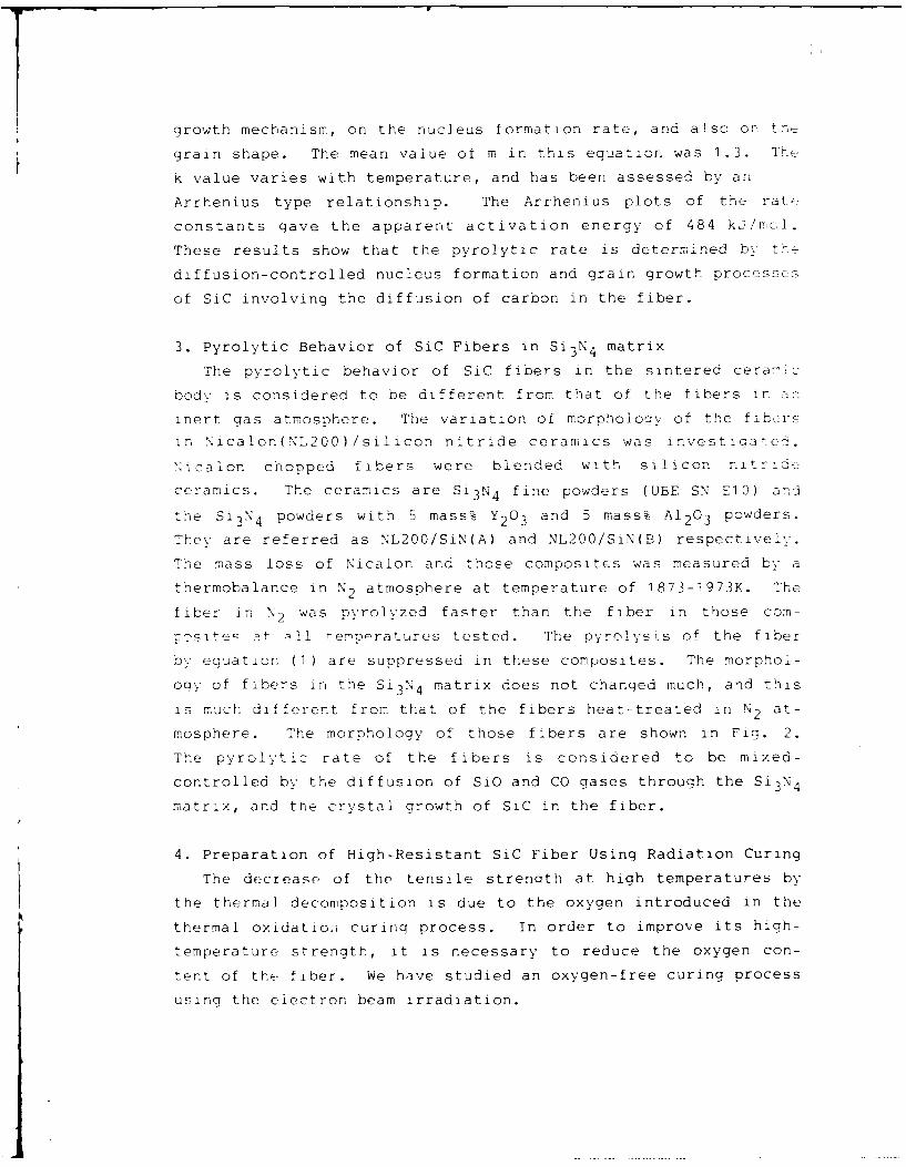
grain shape. The mean value of m in this equation was 1.3. T
k value varies with temperature, and has been assessed by an
Arrhenius type relationship. The Arrhenius plots of the rate
constants gave the apparent activation energy of 484 kj/mol.
These results show that the pyrolytic rate is determined by the
diffusion-controlled nucleus formation and grain growth processes
of SiC involving the diffusion of carbon in the fiber.
3. Pyrolytic Behavior of SiC Fibers in Si 3 N4 matrix
The pyrolytic behavior of SiC fibers in the sintered ceramic
body is considered to be different from that of the fibers inr
inert gas atmosphere. The variation of morphology of the fibers
in Nicalon(NL200)/silicon nitride ceramics was investicated.
Nicalon chopped fibers were blended with silicon nitride
ceramics. The ceramics are Si 3 N4 fine powders (UBE SN El0) and
the Si 3 N4 powders with 5 mass% Y2 0 3 and 5 mass% A12 0 3 powders.
They are referred as NL200/SiN(A) and NL200/SiN(B) respectively.
The mass loss of Nicalon and those composites was measured by a
thermobalance in N2 atmosphere at temperature of 1873-1973K. The
fiber in N2 was pyrolyzed faster than the fiber in those com-
-L-slte- 1 ternprratures tested. The pyrolysis of the fiber
by equation (1) are suppressed in these composites. The morphol-
ogy of fibers in the Si 3 N4 matrix does not changed much, and this
is much different from that of the fibers heat-treated in N2 at-
mosphere. The morphology of those fibers are shown in Fig. 2.
The pyrolytic rate of the fibers is considered to be mixed-
controlled by the diffusion of SiO and CO gases through the Si 3 N4
matrix, and the crystal growth of SiC in the fiber.
4. Preparation of High-Resistant SiC Fiber Using Radiation Curing
The decrease of the tensile strenoth at high temperatures by
the thermal decomposition is due to the oxygen introduced in the
thermal oxidation curing process. In order to improve its high-
temperature strength, it is necessary to reduce the oxygen con-
tent of the fiber. We have studied an oxygen-free curing process
using the electron beam irradiation.

A 14
Fig.2 SEM micrographs of heat-treated SiC fiber(NL200).(a):as received NL200,(b):NL200 heat-treated at 1973K in N2,(c):NL200 heat-treated at 1973K in Si 3 N4 powder,(d):NL200 heat-treated at 1973K in sintered Si 3 N4 matrix.
The synthesis process of SiC fiber with its curing is shown in
Fig. 3. Polycarbosilane(PCS) fiber was irradiated by 2 MeV
electrons under vacuum or in inert gas atmosphere, then the PCS
fiber is crosslinked, and its curing is accomplished above about
10 MGy. The SiC fiber obtained by heating up to 1473K in Ar gas
flow contained the oxygen less than 0.5%. As the original PCS
fiber contains 0.3% or more, it means that there is no oxidation
during the radiation curing. After 1773K heat treatment for 1h,
the tensile strength kept 2.5 GPa at 1473K, and Young's modulus
increased from 220 to 260 GPa. The tensile strength decreased
gradually above 1993K, the morphology of the SiC fiber shows ap-
parently no change after heat treatment at 2273K for 1 h by SEM
observation.

]5
The radiation
curing of PCS fiber
is found to be very Polycarbosilane(P(3S) (-Si - CH2-),useful for develop- CH3
ment of high-heat Melt spinning at 300-320'Cr e s i s t a nt S i C PCS Fiber 15 -20gm ¢fiber. This re- L
search has been Radiation curingElectron beam irradiation
carried out by the IO-l5NGy in He gas flow
fundamental a nd Cured PCS Fiber Hold on fiber abovesmall scale ex- I melting temperatureperimental equip-ments. etuis Change to ceramic by heat-ments . It is treatment at 1800K in Ar gasnecessary to
prepare a con- Silicon Carbide(SiC) 1 2 -- 1 5 ,*mFlexible ceramic
siderable amount of fiberSiC fibers in order
to apply to rein- Fig.3 Process of SiC fiber synthesis by
forcement fibers of radiation curing of PCS fiber.
composites. We
designed and constructed the electron beam curing apparatus,
which is composed of irradiation chamber, sample transfer, and
heat-treatment vessel for the PCS fiber 1 3 ). Using the apparatus,
the PCS fibers of long strand (2km length and about 300g) com-
posed of 500 filaments were cured, and the SiC fibers containing
0.4% oxygen were obtained.
5. Conclusion
(a) The pyrolytic rate of Nicalon type SiC fiber in an inert gas
atmosphere is determined by the diffusion-controlled nucleus
formation and grain growth processes.
(b) The pyrolytic rate of the SiC fiber in Si 3 N4 matrix is mixed-
controlled by the diffusion of SiO and CO gases through the
Si 3 N4 matrix, and the crystal growth of SiC in the fiber.
(c) Heat-resistant SiC fiber is synthesized by the heat treatment
of polycarbosilane fiber with electron beam irradiation
curing. Applying this radiation curing technique, a consid-

erable amount of SiC fiber (about 200q) is svnthes~zed.
References
1) S.Yajima, Am. Ceram. Soc. Bull., 62(1 983)pp.893-98.
2) T.Ishikawa and T.Nagaoki, Recent Carbon Technology Including
Carbon and SiC Fibers(1983), JEC Press Inc., p.348.
3) X.M.Prewo, J.J.Brennan and G.K.Layden, Am. Ceram. Soc. Bull.,
65(1 9 8 6 )pp.305-l 3,322.
4) P.J.Lamicq, G.A.Bernhart, M.M.Dauchier, and J.G.Mace, ibid.,
65(1986 )pp. 347-50.
5) D.P.Stinton, A.J.Caputo and R.A.Lowden, ibid.,65(1986)
pp. 336-38 .
6) X.Qkamura, M.Sato, T.Matsuzawa and Y.Hasegawa, Polyrr. Prepr.,
25(1984 )pp. 6-7.
7) D.J.Pysher, K.C.Goretta, R.S.Hodder,Jr. and R.E.Tressler, J.
Am. Ceram. Soc., 72(1989)pp.284-88.
8) T.Shimoo, M.Sugimoto and K.Okamura, J. Japan Inst. Metals,
54(1990) pp. 802-08.
9) T.Shimoo, Y.Kakehi, M.Sugimoto and K.Okamura, J. Ceram. Soc.
Japan, 99(1991 )pp.4O1 -O6 .
10) K.Okamura, M.Sato, T.Seguchi and S.Kawanishi, Proceedings of
the 4th International Symposium on Science and Technology of
Sintering held in Tokyo on 4-6 November, 1987, pp.102-7.
11) M.Takeda, Y.Imai, 1-Llchikawa, T.Ishikawa, T.Seguchi and
K.Okamura, Ceram. Eng. Sci. Proc., 12(1 9 9 1)pp.lOO 7-1 8 .
12) K.Okamura and T.Seguchi, J. Inorganic and Organometallic
Polymers, 2(1992 )pp. 171-179.
13) T.Seguchi, N.Yasai, and K.Okamura, Proceedings of the Inter-
natinal Conference on Evolution in Beam Applications held in
Takasaki, Japan, on November 5-8, 1991, pp.702-7 0 6 .

17
POLYMER-DERIVED SILICON CARBIDE FIBERS WITH IMPROVED THERMOMECHANICAL STABILITYWm. Toreki, G.J. Choi, C.D. Batich, M.D. Sacks, and M. SaleemDept. of Materials Science and Engineering, University of Florida
Gainesville, FL 32611 U.S.A.
Introduction
Fiber-reinforced composites are of increasing importance in high temperature structuralapplications due to their excellent mechanical properties, such as high strength and highfracture toughness. However, the use of these composites is generally limited to tempera-tures below - 1 200°C due to degradation of fiber mechanical properties at high temperatures.For example, NicalonTh SiC fibers (which have been used to reinforce glass, glass-ceramic,and crystalline ceramic matrices 1"2 ) may show significant decreases in tensile strength andelastic modulus after heat treatment at temperatures as low as 1000,C.1.4 The poorthermomechanical stability is attributed to the presence of oxygen (- 8-15 wt%) and excesscarbon in the fibers which results in the formation of volatile reaction products (primarily COand SiO) at relatively low temperatures." Significant improvements in the high temperaturemechanical properties of SiC fibers might be expected if the oxygen content can be reduced.
Nicalon• fibers are prepared by melt spinning of a low-molecular-weight organosiliconpolymer (i.e., polycarbosilane). As-spun fibers are then heated at low temperature (- 150-200°C) in air in order to cure (cross-link) the polymer and to prevent fibers from melting duringthe subsequent pyrolysis step (in which the polymer is decomposed to a SiC-rich ceramic).In the present study, polycarbosilane-derived SiC fibers were prepared using processingconditions that allowed the oxidative cross-linking step to be eliminated. Therefore, the fibersproduced after polymer pyrolysis and SiC crystallization had very low oxygen content (< 2wt%) compared to Nicalon.'
Experimental
The processing steps used to prepare SiC fibers with low oxygen content are summarized inFig. 1. Polycarbosilane (PC) was synthesized by pressure pyrolysis of polydimethylsilane.Fibers were spun using intermediate-molecular-weight PC's (- 5,000-10,000) which remainedhighly soluble in appropriate solvents, but did not melt during subsequent heat treatment.Polymer solutions were extruded through stainless steel spinnerets (- 70 or - 120 pmdiameter orifices) under nitrogen pressure. Continuous "green" fibers were collected bywinding on a rotating drum and pyrolysis was subsequently carried out at temperatures in therange of 750-1000°C (1 h hold) under flowing nitrogen. Fibers with diameters in the range-10-50 pm were produced.
Thermal gravimetric analysis (TGA), X-ray diffraction (XRD), scanning and transmissionelectron microscopy (SEM and TEM), and elemental analysis were used to characterize thefibers. Fiber tensile strengths were determined at room temperature according to ASTMprocedure D-3379. Fibers were tested after pyrolysis at 10000C and after additional heattreatments in argon at temperatures in the range 1200-17000C.

CONTINUOUS SILICON CARBIDE FIBERS
Polydimethylsilane
I Heat Treatment
Polycarbosilane
Solution/FiltrationPrecipitation/Filtration60 0C/Vacuum
Polycarbosilane (Mp = 5,000-10,000)
l Addition of Spinning AidsAmbient Spinning Conditions
Solution Spun Fibers
1 000 °C/N2
"SiC" Fibers (<2 wt% Oxygen)
FIG. 1. Procpssing steps for preparation of SiC fibers with low oxygen content.
Results
TGA results on as-spun fibers show that pyrolysis reactions are mostly completed below- 9000C. The total weight loss is relatively low (- 20 wt%), especially compared to losses(- 40 wt%) reported for low-molecular-weight PC's (such as used in melt spinning of Nicalonfibers).' In fact, the ceramic yield is comparable to yields reported for oxygen-cured PCfibers.'-
Pyrolyzed fibers (750-1 000°C) had a visual appearance similar to Nicalon'T (i.e., black color).SEM observations showed that outer surfaces and fracture surfaces were smooth. XRDanalysis indicated that 1 000°C-pyrolyzed fibers were substantially amorphous, although verybroad peaks associated with SiC were evident. These peaks progressively narrowed andincreased in intensity for samples subjected to further heat treatment (to 1 600°C in nitrogenor argon atmospheres), indicating that growth of SiC crystallites occurs with increasingtemperature. The same trends were revealed by TEM.

Figure 2 shows a comparison of TGA data for NicalonT' fibers and pyrolyzed (7500C, lh)fibers prepared in this study ("LhF fibers"). Weight loss was monitored as the fibers wereheated in argon at 10°C!r.iin to 16500C and then held for 1 hour at temperature. The UF fiberlost only -3 wt% during this treatment, while the NicalonTM fiber lost -25 wt% Therelatively low weight loss observed for the UF fibers can be attributed to the low oxygencontent. Neutron activation analysis (NAA) of three different UF fiber batches (pyrolyzed at1 000°C) revealed oxygen contents in the range - 1.5-1.8 wt%, while NicalonT fibers showed15 wt% oxygen by NAA.
UF Fibers
Argon 10°C/mln 1 h at 1550 °C
100
95
90I.-
C 85
80
75
70 I, I I0 200 400 600 800 1000 1200 1400 1600 1800
TEMPERATURE ('C)
Nicalon Fibers
Argon 10C1min 1 h at 1550 °C
100
95
~90
w 85
80
75
70 I , I0 200 400 600 800 1000 1200 1400 1600 1800
TEMPERATURE (°C)
FIG. 2. Weight loss behavior for UF fibers (top) and NicalonTM fibers (bottom) heated inargon to 15500C at 1O°C/min and then held for 1 hour at temperature.

2 0
Figure 3 shows average tensile strengths for UF and NicalonTh fibers after heat treatment atvarious temperatures in cn argon atmosphere. It is evident that UF fibers show much greaterretention of strength after heat treatment. The strengths reported in Fig. 3 were obtained froma single batch of UF fibers. Although the data is considered iepresentative, it should be notedthat higher strengths have been observed in some other batches. For example, averagestrengths as high as -3 GPa have been observed for as-pyrolyzed batches (10-15 pm fiberdiameters) and - 1.9 GPa in some batches heat treated at 1400°C (for 1 h). Thus, it may bepossible to produce fibers with consistently higher strength levels than reported in Fig. 3 ifprocessing conditions are more rigorously controlled.
UF - 80 Nicalon3.0-nL V 0.5 h 0D 0.5 h2.5 1.0 h 0 .0h
S2.5zI.UF 2.0I--
-J
, 1.5zwI-LU 1.0
" 0.50
-4
900 1000 1100 1200 1300 1400 1500 1600 1700 1800
AGING TEMPERATURE (-C)
FIG. 3. Plots of average tensile strength vs. heat treatment temperature for UF fibers andNicalonTM fibers.
Conclusion
Continuous silicon carbide fibers with low oxygen content (< 2 wt%) were prepared in a rangeof diameters (- 10-50 p;m) by dry spinning of polycarbosilane solutions and subsequentpyrolysis of the polymer fibers. Average tensile strengths approaching 3 GPa were obtainedfor some batches with fiber diameters in the range - 10-15 pm. These fibers showedexcellent thermomechanical stability compared to commercially-available NicalonTM fibers, i.e.,significantly lower weight loss and higher tensile strength were observed after heat treatmentin argon at elevated temperatures (1200-1 7000C).
Acknowledoement
This work was supported by the Defense Advanced Research Projects Agency under ContractNos. MDA 972-88-J-1006 and N00014-91-J-4075.
References
1. K.M. Prewo, J.J. Brennan, and G.K. Layden, Am. Ceram. Soc. Bull., 05 [21 305-313,322(1986).
2. P.J. Lamicq, G.A. Bernhart, M.M. Dauchier, and J.G. Mace, Am. Ceram. Soc. Bull., 5[2) 336-338 (1986).
3. M.H. Jaskowiak and J.A. DiCarlo, J. Am. Ceram. Soc., 22 [21 192-197 (1989).
4. D.J. Pysher, K.C. Goretta, R.S. Hodder, Jr., and R.E. Tressler, J. Am. Ceram. Soc., _72[21 284-288 (1989).
5. S.M. Johnson, R.D. Brittain, R.H. Lamoreaux, and D.J. Rowcliffe, Comm. Am. Ceram.Soc., 71 (3] C-132 -C-135 (1988).
6. Y. Hasegawa, J. Mater. Sci., 24 1177-1190 (1989).
7. S. Yajima, Y. Hasegawa, and M. limura, J. Mater. Sci., I5 720-728 (1980).

22
`ew Curing Method for Polycarbosilane with Unsaturated
Hy-_ý_drcarbons and the AT;ýlication to Thermally Stable
Si-C Fibre
YOSHIO HASEGAWA
The Research Institute for Special Inorganic Materials,
Asahi-mura, Kashima-gun, Ibarai 3ll-4, JAPAN
introduotion
Continuous SIC fibres synthesized from polvcarbosilane
(PJ precursor are already in industrial production as
NIALOX fiber and TYFANNO fibre, which are used as reinforce-
ments for composites. However, for the purpose of utilizing
SiC fibre as reinforcement in many ceramic matrix composites,
development of oxygen-free Si-C fibre, having high thermal
stability and oxidation resistance, is necessary.
Recently, Si-C-O fibre with a small amount of oxygen
was orepared from PC fibre cured by electron beam irradiatoion
[]. It was shown that this fibre had improved thermal statility.
And then, the auther found that PC was cured by heating in
halogenated hydrocarbon or unsaturated hydrocarbon vapor [2].
--is method, hereafter, is referred to as chemical vapor
curing (CV.) method. In comparison with the electron beam method.
this new method is assumed to be more ecomomical. In the
previous report [2], by CVC method, the fibre heat-treated at
15K•C in a nitrogen gas flow had tensile strengths more than
2G37a. Or. the other hand, in an argon gas flow, the strength

23
decreased racidly above C. was assumed
nitrogen atoms introduced into the fibre depressed cristal- -
tion of s-SiC.
In the present research, the fibre with high thermal
stability has been synthesized ty CVC method and heat-treatment
in an argon gas flow.
Fibre Synthesis
The number average molecular weight of PC is 20%D. PC was
melt-spun at about 3700'. The resultino fibre bundle was cured
c.' heating n a tutular furnace up to a specific temperature
an. argon gas flow containing unsaturated hydrocarbon vapor.
Cyclohexene, 1-hexyne or 1-octyne was used as unsaturated
hydrocarbon. A schematic diagram of the curing apparatus is
shown in Fig.l.
The cured fibre was then heat-treated in a tubular
L.Pnace up to a specific temperature at a rate cf l00 0C-h-
in an arzcn gas flow.
Argcn mas was dried by passing through columns pack;ed
with sutcessive, silica gel, magnesium perchicrate and phosph.-rus
pentoxide.
Mechanical prcperties of fibres were measured at room
temrerature with a 25-mm. gauge length for 30 filaments, the
avera-e values being taken.
R.esults and discussion
Tesile strength and Young's modulus of Cl-C fibres are

24
shown in Fi.2 as a function of the heat-treatment temperature,
in comparison with those of Si-C-O fibres obtained by' thera-
oxidation curing. It appears that the properties of the fitres
obtained by CVC method are higher than tose of Si-C-C fibres.
The IR spectra of Si-C fibres showed no absorption at
1000 % 1100cm- due to Si-O stretching. If oxygen atoms are
present in the fibres, carbothermal reduction or thermal
degradation take place above 1300 0 C with weight loss and
6-Si0 crystal growth. Consequently, the strength of the fitre
decreases. in the fibre obtained by CVC, these hizh-temperazure
reaction should not occur.
In Fig.3, s-SiC crystalline size (LI 1 ) are shown as a
function of the heat-treatment temperature. It is clear that
rapid crystal growth did not take place, while L2,1 gradually
increased with increasing heat-treatment temperature. This
increse of Li'1 may decrease the strength of Si-C fitre as
shown ir, Fig.2. The relation between the tensile strength and
Liii is shown in Fig.4 which supports the decrease of the
strength due to the crystal growth.
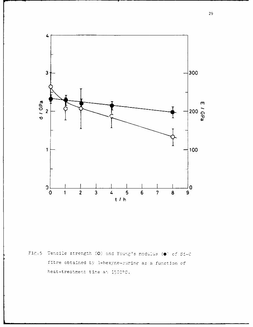
The thermal statility of Si-C fibre obtained by CVC method
with 1-hexyne is shown in Fig.5. The fibre was heated at l5lC
for 0 u 8h. These results show that the thermal stability of
Si-C fibre by CVC method is superior to Si-C-C fibre in non-
oxidizing atmosphere.
The following subject to be studied will be improving the
oxidation resistance of the fibre.

25
ne fe•en:3es
i. u, .to, T .Se and S.Kawanishi, J. Jaran
Scciet$v :f Powder and Powder Metallurgy, 35 (1956) 172.
2. Y.Hasegawa, J. Inorganic and Organometallic Polymers,
2 (1992) 161.
Fibre
A r
Ar -.
00 ei dUnsaturated hydrocarbon
Fig.1 A schematic diagram of thie curing apparatus.

26
4400
(a) (b)
3 300
2 200-2IIIj
0 w
O Air-cured 100
A Cyclohexene -cured
1 :-ctyne-cured - T
1-Hexyne-cured0 i I .0 , I I 1900 1300 1400 1500 1600 1700 900 1300 1400 1500 1600 1700
T I C T I T
Fig.2 ?Te relatir1. tetween heat-treatment temperature anr
(a, te-le -renrth and ()V Yun s C odulus, of s i-f
S. I" C- - i ref

27
5
14
3
10
00 5 10 15
L11Inm
'1rerel,4'i:,. teter r.e7-t-treaent tempperature anl-
crvstalire s ze (L in Si-C and Si-C-Cl
fitres.

28
15
o Air -cured
0 1-Octyne-cured,/
S1-Hexyne I
-cured 1
10-
EC
5
011
0 L I I I
1200 1300 1400 1500 1600 1700
T I'C
i-.~.4 Tensile strer.j.t... c i-' fibre as a function of 6-Sic
crIstLa>-_r4e size TL-K
29
3 -300
-200 c10
1 -100
0 1 2 3 4 5 6 7 8 9t I/h
Ti-~~ensziie strength (0) andý Youn7r's mcd,,1ius (0ý of SI-C
fitre obtained t-, I-hexvne-curinc- as a function of'
heat-treatmernt tire alý lrOOOC.

30
INTERFACIAL CONTROL AND MACROSCOPIC FAILURE ININORGANIC COMPOSITES
T.W".Clvne and A.J.Phillipps
Department of Materials Science and MetallurgyPembroke Street, Cambridge CB2 3QZ, U.K.
tel 44-223-334332 fax 44-223-334567
Interfacial Processes
The nature of the interface has profound effects on the performance of all types ofcomposite material. The central problem concerns inelastic processes at the interfacewhich might be stimulated by the operative stress field. Some such processes (whichmignt operate in metal- or ceramic-based composites) are shown schematically inFig.l, together with a possible set of stresses in the vicinity of the interface. Forceramic matrix composites. there is a clear requirement that the interface besufficiently "weak" to allow debonding. and the associated energy-absorbing processes.to be stimulated by the local stresses set up when the material is loaded'. Interfacialfracture is therefore the key process in such composites. There have been significantadvances over recent years concerning interfacial fracture mechanics, particularly forbimaterial interfaces 2 6
For metal matrix composites, the situation is somewhat less clear. Although thematrix has an enormous potential for energy absorption via dislocation motion, thiswill in general be much more difficult to promote than in a monolithic metal becauseof the constraint to matrix plasticity offered by the reinforcement. Under thesecircumstances, there could in principle be scope for significant toughness enhancementin MMCs as a consequence of inelastic processes occurring at the interface. Inpractice, a strong bond is probably beneficial in most cases since it will delay the onsetof failure. However, the interplay between microstructure, stress state and the natureof the inelastic processes can be highly complex and is further complicated in manyMMCs by the scope for progressive interfacial chemical reaction7 , which cansubstantially alter the mechanical response characteristics of the interface.

31
I Cavitationt a S sIn e as Interfacial P rocse
( fa ( a SdFrictional SlidingInterfacial Crack• ii:i~:•ii•l | ' >"
Propagation R Rates f Propagation)
e I stefinI Interfacial
i ~ ~ ~ ~ ~ ~ Nr nterfaceicopstmarials.Teeivlestain agn 8 1 rmsn1firepulotan pshuttst t itefcil rakngd urn ing nghfeamiats
prpet oteInterfacia tesIsb measurd Aneimoranti ponttrfaistat diffeentsest
(Differential Thermal Contraction and (Critical Stresses for Onset and Critical StrainElastic Stresses from Applied Load) Energy Release Rates for Propagation)
Fig. I Schematic depictire of possible stress state variations In the vicinisi of a fibreembedded in a tnatri.v atnd soine qf the inelasti.c' processes wvhich can be stimulated
at tile I'lterjc('ie t•i .uh1 stresses.
Interfacial Testing
A variety of tests have been developed to measure mechanical characteristics of theinterae om ite rials. These involve situations rangingrl from singlefibre pullout and pushout tests to interfacial cracking during bending of laminates.There are, however, often difficulties in identifying precisely what mechanicalproperty of the interface is beimng measured. An important point is that different testscover a range of' proportions of' opening and shearing mode stress intensities at thecrack tip. Parameters being measured, such as a critical shear stress for the onset ofdebonding or a critical -value of the interfacial strain energy release rate, will varywith this proportion. An increasingly popular approach12-14 to the characterisation ofthis mode mixity is to identify the so-called phase angle, W, (=tan-l(Kil/Ki)), althoughthere are some difficulties wi~th this approach -particularly when compressive

stresses are present. It can be seen from Fig.2 that measured values of interfacialparameters can vary quite sharply with mode mixity, which can range from pureopening (y=O) to pure shear (y=90'): in general, resistance to crack propagationrises with predominance of shearing over opening mode, as frictional work in thewake of the crack tip increases.
DoubleCantilever
Beam
r t4-point bendI I from frictional ,.., u -35' -60ý .,II work, p~astic + - "
from work of adhesion
0o 45* 945W
Tensioned -."''-"•," / Push-out
CompositeCylinder
(FibrePull-out)
ratO-90' 70' - 90O
Fig.2 Schematic illustration oft/he dependence of the interfacial critical strainenergy release rate, Gi(. on the phase angle of loading mode mixity, V. Different
tests involve a wide range of y values.
Interfacial Modification
There are several ways in which useful modifications to interfacial features can beeffected in inorganic composites. For example, careful control over the structure ofgraphitic interfaces in SiC laminates can ensure that the value of Gic is sufficiently low,

33
relative to G,. for the bulk SIC'. to en.sure that transverse cracks are consistentl\deflected15. For MMCs, the concern is often more likely to be prevention of theformation of brittle intefacial reaction layer•. For example, duplex C/TiB2 coatingsl•'
have been deposited by CVD during fabrication of SiC fibres to be used in titaniumcomposites. Studies have also been carried out on duplex yttrium/yttria coatingsdeposited onto SiC by sputtering•7. This system is thermodynamically stable in Ti at
high temperature and, sixlce there is scope during the sputtering process for inducinghigh compressive stresses1•' in the coating by' atomic peening see Fig.3, the
problems of deposit cracking as a result of differential thermal contraction stresses can
be overcome.
In-plane S're•,.,, inQuen•.hcd m L)tlierenlnalCoating tit ROOlI1 / Va,..•,Jc-, •'t•
]cn•pc r;atur c • / .. thermal. " " " •()l]irglCl.ld )Wl
T,.'n:.;tn '"'•. ... -"" / Resultant
.,- -'%•
,• Te m pcrat ureRoL•I•
Compression •'nper atu r v.
"ato/lllc|2Pt-Clullg '
Fiz.3 Sc]letla[l•. illu.st, a:i<m of •.tlFlg)lt3 { ,)*ztri/•z•tion., t¢: the sires:, state at roomtemperature in a sputtered 3ttria la• c'p on a SiC mon(qilament, as a function of the
coating;/•d•ri{ation temperat, ,e.
Macroscopic Deformation and Failure
One of the major challenges in the development of advanced composites is toestablish quantitative correlation.,, betaeen mechanical characteristics of the interfaceand composite properties - particularl', those concerning plastic deformation andfailure. The current situation varies shtrply depending on the type of compositeconcerned. At one extreme, it is no'• possible to develop models completelydescribing the fracture behaviour under 3-point bending of laminates made up ofbrittle sheets joined b,, interfaces of specified toughness. For example, a comparisonis shown in Fig.4 bet'aeen measured and predicted load-displacement plots for such alaminate, with the series of peaks representing the onset of fracture of successivelayers and sub.,,equent crack deflection b v the interfaces. It is acceptable to take a

34
constant value for Gi,: since the variation of y as the crack propagates along such alaminate is small. Agreement can be improved by the use of an appropriate Weibullmodulus, m, in the modelling, although obviously the actual distribution of peakheights can only be predicted on a statistical basis.
I c= 28Jm2
Gic= 8Jm 2
80 6=300 ýimn = 14
' 60 -notch = 5 layersam,= 630 MPa
0- 40- m-o6 L 38 mm-0 20- Measured Predicted
0
-
0 1 2 0 1 2
Roller displacement (mm)
Fig.4 Experimental and predicted load-displacement plots for notched SiClaminates in 3-point bending.
The above situation is highly amenable to modelling because the matrix is brittleand the crack geometry is simple. Fibre composites are inevitably much morecomplex geometrically, with the mode mixity at an interfacial crack usually varyingwith position both around the fibre circumference and along its length. In addition,for metal matrix composites there is substantial scope for energy absorption andplastic deformation within the matrix and predictive modelling of this is difficult, evenwith recourse to numerical methods' 9. Nevertheless, some predictive capabilityrelating interface characteristics to composite performance can be established. Forexample, it has been shown 20 that continuous monitoring of the Poisson's ratios duringtensile loading of long fibre reinforced Ti can reveal whether matrix plasticity orinterfacial debonding and damage are responsible for observed inelastic behaviour andthis can be correlated with measured interfacial properties. There is also some scopefor predicting whether interficial energy absorption could be significant in differentsituations, in general, it would appear that this is only possible if very pronounced

35
fibre pull-out can be stimulated and even then the contribution is only likely to bereally important in relatively brittle metals, such as zinc21 22
References1. A.G. Evans, F.W. Zok and J. Davis. The Role of Interfaces in Fiber-Reinforced
Brittle Matrix Composites, Comp. Sci & Tech., vol.42, (1991) p. 3 -2 4 .
2. J.R. Rice, Elastic Fracture Mechanics Concepts for Interfacial Cracks, J.App.Mech. (Trans. ASME), vol.55, (1988) p. 9 8 -10 3 .
3. M.S. Hu, M.D. Thouless and A.G. Evans, The Decohesion of Thin Films fromBrittle Substrates, Acta Metall., vol.36, (1988) p. 13 0 1- 13 0 7 .
4. M. Hu, The Cracking and Decohesion of Thin Brittle Films, Materials ResearchSociety Symposium, vol.130, (1989) p. 2 13-218.
5. A.G. Evans, N1. R.ihle, B.J. Dalgleish and P.G. Charalambides, The FractureEnergy ofBi'material lnte'jace,, Mater. Sci. En-._ vol.A126. (1990) p. 5 3 -6 4 .
6. Z. Suo and J.W. Hutchinson, Inter]ace Crack Between Two Elastic Layers, Int. J.Fract., vol.43, (1990) p. 1 -1 8 .
7. T.W. Clyne and M.C. Watson, Interfacial Mechanics in Fibre-reinforced Metals,Comp. Sci. Tech., vol.42, (1991) p. 2 5 -5 5 .
8. P.S. Chua and M.R. Piggott, The Glass Fibre-polymer Inteiface: I TheoreticalConsiderations for Single Fibre Pullout Tests, Comp. Sci. Tech., vol.22, (1985)p.33-42.
9. P.G. Charalambides, H.C. Cao, J. Lund and A.G. Evans, Development of a Testfor Measuring the Mixed Mode Fracture Resistance of Bimaterial Interfaces.Mech. Mater., vol.8, (1990) p. 2 6 9 -2 8 3 .
10. M.C. Watson and T.W. Clvne, The Use of Single Fibre Pushout Testing toExplore Interfacial Mechanics in SiC Monofilament-reinforced Ti. Part I : APhotoelastic Study ofjthe Test, Acta Metal et Mater, vol.40. (1992) p.135-140.
11. M.C. Watson and T.W. Clyne. The Tensioned Push-Out Test for Measurement ofFibre/Matrix Interfacial Touglhness unler Mixed Mode Loading, to be publishedin Scripta Met,(1992)
12. B. Budiansky and J.W. Hutchinson, Matrix Fracture in Fiber ReinforcedCeramics, J. Mech. & Physics of Solids, vol.34, (1986) p.167-189.
13. J.W. Hutchinson and Z. Suo, Mixed Mode Cracking in Layered Materials, Adv.Appl. Mechs., vol.28, (1991 )
14. J.W. Hutchinson. Mixed Mode Fracture Mechanics of Interfaces, Report, HarvardTechnical Report, Mech-139. (1989), Division of Applied Sciences, HarvardUniversity, Cambridge, MassachusettS, USA.

36
15. A.J. Phillipps, W.J. Clegg and T.W. Clyne, The Effect oJ Processing Variahles onthe Intera~cial and Ma roscoph Touaihnese.. of SiC Laminates, to be published inComposites, (1992).
16. N.A. James, D.J. Lovett and C.M. Warwick, Mechanical Behaviour of aContinuous Fibre Reinforced Titanium Matrix Composite, in "Composites:Design, Manufacture and Application (ICCM8)", S.W. Tsai and G.S. Springer(eds.), Hawaii, USA, SAMPE, (1991) p.19I/1-191/10.
17. R.R. Kieschke, R.E. Somehk and T.W. Clyne, Sputter Deposited Barrier Coatingson SiC Monofilaments for Use in Reactive Metallic Matrices - Part /Optimization of Barrier Structure, Acta Metall.et Mater., vol.39, (1991) p.427-436.
18. C.M. Warwick, R.R. Kieschke and T.W. Clyne, Sputter Deposited BarrierCoatings on SiC Monofilaments for Use in Reactive Metallic Matrices - Part 1ISystem Stress State, Acta Metall. Mater, vol.39, (1991) p. 4 3 7 -4 4 4 .
19. J.R. Brockenbrough, S. Suresh and H.A. Wienecke. Deformation of MMCs withcontinuous fibers: geometrical effects of /iber distribution and shape, Acta Metall.Mater, vol.39, (1991) p.735-752.
20. M.C. Watson and T.W. Clvne, Reaction-induced changes in Interfacial andMacroscopic Mechanical Propertie.s ol SiC Monofilament reinforced Titanium, tobe published in Composites, (1992)
21. F. Vescera, J.P. Keustermans, M.A. Dellis, B. Lips and F. Delannay, Processingand Properties of Zn-Al Alloy Matrix Composites Reinforced by BidirectionalCarbon Tissues, in "Metal Matrix Composites - Processing, Microstructure andProperties, 12h Riso Int. Symp. on Materials Sci.", N.Hansen, D.J. Jensen, T.Leffers, H. Lilholt, T. Lorentzen. A.S. Pedersen, O.B. Pedersen and B. Ralph(eds.), Roskilde, Denmark, (1991) p. 7 19 -7 2 4 .
22. W. Chengfu. Y. Meifang and W. Zhangbao, Analysis of Fracture Features ofCarbon Fibre Reinfrrced Zinc base alloy Composite. in "6th InternationalConference on Composite Materials", F.L. Matthews, N.C.R.Buskell, J.M.Hodgkinson and J. Morton (eds.), London, Elsevier, (1987) p. 2 .4 7 6 -2 .4 8 0 .

37
The Role of Fiber/Matrix Interface
in The First Matrix Cracking of
Fiber-Reinforced Brittle Matrix Composites
Takayuki Suzuki and Mototsugu Sakai
Department of Materials Science
Toyohashi University of Technology
Tempaku-cho, Toyohashi 441, JAPAN
INTRODUCTION
In a brittle/brittle composite system, such as ceramic-fiber/ceramic-matrix system
composed of reinforcing fibers and matrix with very similar values of the elastic moduli
and the fracture toughness values, a propagating matrix crack is unlikely to "recognize"
the fiber at the interface, if the interface bonding is perfect. The matrix crack will extend
into and through the fiber without interface debonding, crack face bridging and subse-
quent fiber pullout along the fracture path. The composite failure is thus very brittle andcatastrophic. Little or no property enhancement will be expected in this form of compos-
ite failure. In order to attain increased toughening in brittle/brittle composite systems,it is required for the interface to have a certain optimum bonding force which is strong
enough for stress transfer, yet weak enough for considerable interface debonding, being arequisite for toughening brittle matrix composites through fiber bridging and subsequent
fiber pullout processes. The stress-induced interface debonding may also be expected tohave an important role in the first matrix cracking of brittle matrix composites. In this
paper, the fracture toughness for first matrix cracking of unidirectionally reinforced carbon-
fiber/carbon-matrix and carbon-fiber/SisN 4-matrix composites is studied in relation to the
ratio of elastic moduli E 1/E, between the fiber and the matrix as well as to the difference
in the interface bonding nature.
EXPERIMENTAL
Test Samples
A carbon-matrix composite (C/C) (Nippon Steel Co., Ltd.) and an Si 3N4-matrix
composite (C/S) (Noritake Co., Ltd.), both of which are unidirectionally reinforced with
carbon fibers, were used. In the C/C-composite, PAN-based carbon fibers (7 pm in diam-
eter, tensile strength of 3 GPa for the gage length of 25 mm, Young's modulus of 230 GPa)
with phenolic resin were heat-treated at 1000 *C, followed by impregnation/carbonization

38
processes for four times and finally baked at 2000 °C. The fiber content, bulk density, andthe Young's modulus of the resultant composite were 56 vol%, 1.63 g/cm', and 200 GPa,
respectively.
Mesophase pitch-based carbon fibers were used for the C/S-composite. The fiberstrength (gage length of 25 mm) and the Young's modulus are 2 GPa and 500 GPa,respectively. The fibers were shaped with SisN 4-slurry by a filament winding methodto make green bodies, and then heat-treated at temperatures from 400 to 700 °C to
eliminate the organic binder, followed by hot-pressing at 1500 *C. The fiber content ofthe resultant composite was 35 vol%. Some characteristic material properties include thebulk density of 2.55 g/cms, porosity of 5.70 %, and the thermal expansion coefficient andthe Young's modulus along the direction of reinforcing fibers are 5.4 x 10- 7/deg and 310
GPa, respectively.
Fracture Toughness Test for First Matrix CrackingThree-point flexural test specimens with different dimensions, the thickness B = 5.7,
12 rmm, and the width W = 1.6, 1.2 mm, were machined. The tensile (or compressive) axisof the flexural specimen coincides with the reinforcing fiber axis. In order to introduce a
controlled semi-elliptical surface flaw on the surface at a right angle to the tensile stress,a thin steel blade (0 5mm) with the tip radius less than 5 jim was used. Since the con-ventional fracture mechanics test specimen geometry with a straight-through notch, suchas the compact tension or the single edge-notched bend specimen, yields a plane-stress orplane-strain at the notch-tip, the crack does not extend across the unidirectionally rein-forcing fibers, but instead propagates along the fiber direction by delamination cracking.
However, because of the triaxial stress-strain state of the semi-elliptical surface flaw, the
present flexural test specimen avoids such undesirable delamination cracking at the crack-tip, and results in an ideal matrix cracking, the crack plane passing through the composites
at a right angle to the reinforcing fibers. The fracture toughness K, for matrix cracking ofthese composite materials was examined by changing the size of the surface flaw ranging
from 10 to 400 ym in the depth.
A special type of displacement-controlled test apparatus was designed for the presentstudy for first matrix cracking. A precise determination of the onset critical load for firstmatrix cracking, which occurs at the bottom of the semi-elliptical surface flaw, was easilyconducted through the in-situ optical observation of cracking at the bottom of the surfaceflaw during the flexural loading over the test span, S = 40 mm. The details of the flexuraltest apparatus have been reported in the literature.

39
RESULTS AND DISCUSSION
The interrelationships of the fracture toughness K, for first matrix cracking and thedepth b of the surface flaw are plotted in Fig. 1 for the C/C- and the C/S-composites.The K,-values are nealy constant (7.0 ± 0.6 MPav/' for the C/C- and 5.2 ± 0.5 MPav'¶-for the C/S-composites) over a wide range of the surface notch depth. The normalizedtoughness improvement by fiber reinforcement (Kc/K,) (the composite toughness K,divided by the fracture toughness K, of the unreinforced monolithic carbon or Si3 N4
used for the matrix) is illustrated in Figs. 2(a) and 2(b). It is worthy of note that the
toughness improvement of the C/C-composite (Kc/Km, 7.0) is considerably higher thanthat of the C/S-composite (Ke/Km - 1.3). Miyajima and Sakai have demonstrated thatthe toughness improvement can be expressed by
K,K,_ = (SSC)db " (SSC)d (1)
where (SSC)db and (SSC),I stand for, respectively, the contributions of stress shieldingby the fiber/matrix interface debonding processes in the frontal process zone and by theinternal elastic stress partition between fiber and matrix due to the difference in their
elastic modulus. The latter contribution ((SSC),z) of the elastic shielding is given by
(SSC')' V/ E(2)EmV
where E,, E,, and v,, are the elastic moduli of the composite and the matrix, and thevolume fraction of the reinforcing fibers, respectively. The numerical relations of (SSC).,
versus the volume fraction of matrix are shown in Fig. 2 by solid lines. The elastic stressshielding effect of the C/C-composite [(SSC),1 _ 3] actually exceeds that of the C/S-composite [(SSC),1 ; 0.8]. This difference in the elastic stress shielding effect mainly
arises from the significant difference in the ratios of the elastic moduli Ec/Em of theC/C-composite (L 20) and the C/S-composite (;- 1.1), as easily expected from Eq. (2).
The finite discrepancies between the experimental results (circles with a vertical barshowing experimental variations) and the theoretical predictions ((SSC),z-curves) in Figs.2(a) and 2(b) can be accommodated to the stress shielding coefficient (SSC)db by sub-stituting (SSC)db = 2.5 for the C/C-composite, and _ 1.5 for the C/S-composite. Thedifferences in the E,/E,-values as well as in the interface bonding nature between the
C/C- and the C/S-composites may yield this important difference in the interface debond-ing stress shielding.

10
COa-
& 0
00,C 5
"- 000
(V 0: C/C
- 0: C/S
CU,
2-
0• I I I
0 100 200 300 400 500Surface flaw depth, b(gm)
Fig. 1 Fracture toughness values for first matrix cracking of a carbon-fiber/carbor.-
matrix composite (C/C) and a carbon-fiber/SisN 4-matrix composite (C/S).

41
10 2(a)C/C-composite (b)C/S-composite
CJM
0 0
-C 1
0 0.5 1.0 0 0.5 1.0
Volume fraction of matrix, V,
Fig. 2 Normalized fracture toughness values of the C/C- and the C/S-composites.Solid lines represent the theoretical predictions (Eq. (2)) for elastic stress shielding.

42
ISSUES IN THE CONTROL OF FIBER-MATRIX INTERFACE
PROPERTIES IN CERAMIC COMPOSITES
Ronald J. Kerans
Wright Laboratory / Materials Directorate
Wright-Patterson AF1, Ohio 45433-6533, USA
ABSTRACT
The current interest in ceramic composites is a consequence of their
potential for dramatically improved damage tolerance as compared to
monolithic ceramics while delivering similar high temperature properties. This
damage tolerance is accomplished through local accommodation of
overstresses by microcracking. The existence of microcracks in a damaged
composite has clear implications regarding environmental resistance. There
has been much discussion about either using composites at stresses below
matrix cracking or developing oxidation resistant interface treatments.
However, careful consideration leads to the conclusion that the former is not
viable and that oxidation resistant interface control is a necessity. Damage
tolerance is not an occasional requirement, but a pervasive consequence of the
lack of knowledge and control of the stress state in an actual part. This means
that all parts will be at least locally microcracked. The consequence of this is
that the most productive uses of ceramic composites in heat engines are
dependant upon the development of oxidation resistant interface treatments; an
area in which there has been relatively little progress.
It is evident that the fiber debonding and sliding that accompany the
inception and propagation 01 cracks are important factors in determining the
mechanical behavior of ceramic composites. They are also complicated
processes dependant upon several variables. Numerous issues exist
regarding measurement and interpretation of interface properties and
elucidation of the roles of these variables. The development of viable
approaches to interface control will be greatly aided by comprehensive
understanding of these factors.
If a composite is to be toughened by the presence of the fibers, It Is
necessary that the fibers are bypassed by the matrix crack. If the toughness of
the irnterface is too high, or if the frictional resistance to sliding of an unbonded

43
interface is too high, the fibers will fracture. Therefore, we expect both the
interfacial toughness and friction to be important in determining if crack bridging
can occur.The magnitude of the frictional resistance to the sliding of the fiber
determines how far the debonding crack propagates and the energy expended
during pull-out after the fiber breaks. Since the friction will depend upon
residual stresses, coefficient of friction, roughness of the fiber, and abrasion of
the interface; these are all important factors. Furthermore, they are not all
constants. Abrasion and roughness effects are functions of sliding distance.The effective coefficient of friction might also be expected to change with the
accumulation of abrasion debris in the interface. It is expected then, that to fully
understand and control interface behavior, it is necessary to measure and
understand the roles and contributors to the interfacial toughness and interfacial
friction, and the changes in these quantilies with time and environmental
exposure.
All of these factors will affect the design of interface control treatments. Inaddition, time dependent factors will further constrain the designs. Required
coating thicknesses will depend in part on the fiber roughness and on the rate
of microstructural evolution of both fiber and matrix. Composite lifetimes may
depend strnngly on the rate at which fiber or coating oxidation changes
interface properties. A stable, oxidation resistant fiber is essential to the most
dramatic impact of ceramic composites, but the fiber - matrx interface Is a no
less important link in composite performance. Without equally sophisticated
interface control, the best composites will turn into expensive monoliths.

44
Recent Progress in the Design of AdvancedHigh Temperature Composites
byJ. Economy
University of IllinoisUrbana, IL
In this paper recent progress in our group on new types ofreinforcing agents and matrices is described with particular emphasis onsystems with enhanced performance, ease of processing and potentiallylower costs. Continuous multi-filament yarns under study include boronnitride (BN) and boron carbide (B4 C). Work on high aspect ratio, singlecrystal flakes of aluminum diboride (AIB 2 ) as a reinforcement foraluminum is summarized. In addition, recent studies on developing novelorganic oligomers for use in a one step process for fabrication ofcarbon/carbon composites is described. A precursor to a BN matrix hasbeen designed and successfully demonstrated.
Boron Nitride Fibers
BN fibers were successfully prepared in the 1960's by reacting boricoxide filament with ammonia in a batch process over the temperaturerange of 3500 to 850'C. Stretching of the fibers at 2000'C (-17%) resultedin orientation of the layered structure to produce a high W/E fiber similarin properties to carbon fibers. This earlier work is now being revisitedwith the goal of designing a continuous process for drawing, nitriding andstretching the filament yam. If successful such a process could yield a lowcost route to BN fibers since the fiber is formed in 70% yield from thereaction of relatively cheap starting materials; namely, B20 3 + NH 3 . BNfibers display far better thermooxidative stability than carbon fibers i.e.9000 C vs 450'C and are resistant to many molten metals. In this paperrecent progress on achieving the goal of a low cost continuous process isdescribed along with a brief comparison of properties between BN andcarbon fibers.
Boron Carbide Fibers
B4C continuous filament yarn has been successfully prepared byreaction of a precursor carbon yarn with BCI3 + H2 at temperatures of1800'C followed by tensioning at 2150°C. Such fibers display averagetensile strengths of 350,000 p.s.i. and a modulus of 50,000,000 p.s.i.(carbon fiber is converted to - 70% B 4 C). Since B4 C is known to retain mostof its mechanical properties up to 1600-1700TC, it would be an excellent

45
candidate for design of ceramic composites for use at 1000-1300°C. Toaddress the problem of limited oxidation resistance of B4C above 10000C, aprogram is being initiated to further convert the B4C fibers to B4 Si fiberswhich hopefully will display oxidative resistance similar to SiC.
Aluminum Diboride Single Crystal Flakes
AIB 2 flakes have been prepared with high aspect ratio (200/1) andshown to provide outstanding planar reinforcement in epoxy composites(flexural/tensile/compressive moduli values range from 40-45,000,000ps.i. at 65% loading). The flakes which are crystallized from moltenaluminum are unfortunately isolated in the presence of a number of othercubic crystals such as A1B 12 , C2A13B48,MgcABI4 and C4 AIB2 4 . This of coursenecessitates an extensive separation procedure which negates their directuse as a reinforcement of aluminum. The program currently underway isdesigned to eliminate formation of the undesirable crystals permittingconcentration and processing of the flakes in molten aluminum to yield thedesired composite shape in one step.
Design of One Step Precursors to Carbon and Boron Nitride Matrices
Carbon/carbon composites have been available for over 25 years as acommercial product. Typically, the manufacturing process requiresmultiple reimpregnations with phenolic, pitch or furfural oligomers tobuild up the carbon yield, and this is usually followed by a CVDimpregnation of carbon from methane. Total time of manufacture can runup to 5-6 months making for a rather unwieldy process. In our programwe have designed a diacetylenic oligomer which carbonize in 95% yield at800'C. This system has been used to fabricate carbon/carbon compositesin one step in an overall reaction time of 30 minutes.
Similarly, borazene has been found to convert to BN in - 90% yield onheating from 70'C to 1000°C. In our program we have prepared carbonfiber (PAN based) reinforced BN matrix which displays outstanding"mechanical properties e.g. - 15,000,000 flexural modulus and 130,000 p.s.i.flexural strength. The composite was annealed at 1200C for 30 minutes.Further work is being carried out to better characterize the nature of theBN at the carbon fiber interface and also to improve the degree of order inthe BN structure (i.e. reduce the interlayer spacing to 3.40A).

46
PRESSURELESS SINTERING OF SILICON NITRIDE COMPOSITE
T.Yonezawa, S.Saitoh, M.Minamizawa, T.MatsudaJapan Metals & Chemicals Co., Ltd.No.8-4, Koami-cho, Nihonbashi, Chuo-ku, Tokyo 103, Japan
ABSTRACT
Silicon nitride composites containing up to 20 wt% siliconcarbide whiskers were slip casted to orient the whiskers twodimensionally, parallel to the plaster mold surfaces. Thesintered body with 20 wt% whiskers showed 98% relative density,950 MPa flexural strength and 7.0 MPa.m'/ 2 fracture toughness.Also the thermal shock resistance was found to be as high as950 oC.
INTRODUCTION
Silicon nitride ceramics have a good balance of various proper-ties such as strength, toughness, thermal shock resistance,oxidation resistance and the like. Wide applications of siliconnitride ceramics such as use for automobile parts are now beingdeveloped. Parallel with the development of such applications,further improvement of the properties of silicon nitride ceramicsthemselves is being promoted steadily.
Current studies of the composite ceramic materials are also nowactive in order to obtain remarkably improved properties. Inparticular, whisker reinforced ceramics (denoted as WRC) areattracting a great deal of attention.'0 However, there are veryfew reports describing the mechanical properties of pressurelesssintered WRC 2
-4)and the reported data are still unsatisfactory,because of the network of whiskers in the green body. The whiskerdoes not shrink during pressurless sintering, and the whiskernetworks prevents the material movement. Then, the sinteredcomposite has a lot of pores and low strength (shown as Fig.1-a).
Hot pressing method has been used conventionally for the pro-duction of a high dense WRC.5-7) During hot pressing, the pressuredestroys the whisker networks and rearranges whiskers orientedtwo dimensionally (shown as Fig.l-b). WRC can be densified per-fectly using the hot pressing method, but the shapes of hotpressed products are limited to the simple ones, and thefabrication cost of the products are also expensive. In order toextend practical application of WRC, the densification bypressureless sintering (up to I MPa) must be performed.
If we would make a green compact in which the whiskers wereoriented one or two dimensionally, the shrinkage toward theoriented direction could be hindered significantly, but thesufficient shrinkage could be possible toward the directionperpendicular to the oriented direction (shown as Fig.1-c).
From these points of view, we had compared and examined variouscompaction methods, and as a result, we believe that the slipcasting method is the highest possible method in terms oforienting whiskers one or two dimensionally and also in terms of

47
industrial application. We had succeeded in densifying a WRC by
pressureless sintering and manufactured some practical wares.E-1:"
EXPERIMENTAL PROCEDURE
The silicon nitride powder (grade: SNP-8S, Japan Metals &Chemicals Co., Japan), the silicon carbide whiskers (grade: TWS-100 and TWS-400, Tokai carbon Co., Japan), the sintering aids andthe deionized water were mixed in an alumina ball mill for 46hours with addition of the deflocculant. The average diameter andlength of TWS-100 and TWS-400 are 0.4 pm and 30 pm, 1.3 Mým and 50tm, respectively. The amount of whisker was 0, 10, 15 and 20 wt%.The mixtures of yttria (99.99% pure, Shin-etsu Chemical Co.,Japan), alumina (grade: AKP-30, Sumitomo Chemical Co., Japan) andCordierite (grade: SS600, Marusu Yuyaku Co., Japan) were used asthe sintering additives and those amount was 12 and 15 wt%. Afteradjusting the viscosity to about under 50 mPa-s b, adding water,the slips were casted in molds of plaster of P..ris. The solidcontent of the slips were about 70 wt%. The green compacts (50 by50 by 6-10 mm) were dried and then sintered in the range of 1600to 1750cC for 5 hours at 0.1 MPa of nitrogen ur 18250C for 2 to 6hours at 1 MPa of nitrogen. The bulk density i as measured by theArchimedean displacement method using toluen. The relativedensity was determined by dividing the bulk density by the truedensity calculated from the composition of the startingmaterials. The flexural strength was determined by three-pointsflexure on bars having the dimension of 3.0 by 4.0 by 40.0 mm,with polished tensile surface (JIS-R-1601). The fracuturetoughness was obtained by Single Edge Precracked Beam method(JIS-R-1607). The thermal shock resistance was determined asfollows. Inserting theflexure bars into a resistance heated tubefurnace, soaking 10 tol5 min at given temperature and thenquenching into a water-bath (25 OC). The test bars were thenbroken in three-point flexure at room temperature and theflexural strengths were measured. The microstructure of the greenand sintered bodies were studied by an optical and a scanningelectron microscopy.
RESULT AND DISCUSSION
By controlling the properties of the slips, we got the greencompact in which the whiskers were oriented two dimensionally.Seeing from the direction parallel to the mold surface with theoptical microscope, the whiskers were alignment in the samedirection, but seeing from the direction perpendicular to themold surface, the whiskers were randomly distributed.
Figure 2 shows the anisotropic shrinkage and the relativedensity of the composite. As the whisker content increases, theanisotropic shrinkage increases and the relative densitydecreases. The shrinkage toward perpendicular direction is 1.5to 2.3 times larger than the one toward parallel direction. Therelative density increases as the sintering temperatureincreases. And the relative density of composite containingTWP-400 is higher than the one containing TWS-100. As thesintering time increases from 2 to 4 hours, the relative densityof the composite with 20 wt% TWS-400 goes up to 98%.

48
Figure 3 shows the flexural strength and the fracture toughnessof the composite with TWS-400 sintered at 1825 0 C. As the whiskercontent increases, the fracture toughness increases but theflexural strength reduced at 20 wt%, and it occurred from lowrelative density. The sintered body with 20 wt% TWS-400 sintered4 hours showed 950 MPa flexural strength and 7.0 MPa.ml, 2 fracturetoughness,
The composite has a excellent thermal shock resistance. Mono-lithic silicon nitride sintered at 1750 0C exhibited 800 0C of acritical thermal shock temperature difference, on the other hand,the composite sintered at 1750 0C with 10 wt% of TWS-100 gets950 CC of a critical thermal shock temperature difference whichis 20% improvement.
APPLICATIONS
These new composite materials for which we named "KRYPTONITE"have superior thermal shock resistance to the conventionalsilicon nitride. So, the various applications in severe workingconditions, where rapid or local heating is necessary, will bedeveloped. For example, the heatertube, stokes, ladles, etc. usedin an aluminum casting factories are expected as the specifidapplication. The ladles for 0.3 to 1.5 kg molten aluminum andthe crucibles for 3 kg molten aluminum are manufactured
CONCLUSIONS
By orientating whiskers for two dimensionally in the siliconnitride matrix using the slip casting method, the high dense WRCare produced by pressureless sintering. The sintered compositeshave good mechanical properties especially excellent thermalshock resistance and been applied as ceramic parts for moltenaluminum casting.
REFERENCES
(1)S.Yamada, ONRFE Scd. Bull. 12141,17-44, (1987)(2)N.Tamari, I.Kondoh, S.Kamioka, K.Ueno and Y.Toibana, Yogyo-kyokai-shi,94[ll],l177-79, (1986)
(3)T.Kandori, S.Kobayashi, S.Wada and O.Kamigaito, J. Mater.Sci.Lett.,6[11],1356-58, (1987)
(4)M.J.Hoffman, A.Nagel, P.Greil and G.Petzow, J.Am. Ceram. Soc.,72151,765-69,(1989)
(5)K.Ueno and Y.Toibana, Yogyokyokai-shi,91[111],491-97, (1983)(6)R.Lundberg, L.Kahlman, R.Pompe, R.Carlsson and R.Warren, Am.Ceram.Soc.Bull.,66121,330-33, (1987)
(7)S.T.Buljan, J.G.Baldoni and M.L.Huckabee, ibid.,66[21,342-52,(1987)
(8)S.Saitoh, M.Minamizawa, T.Yonezawa, T.Matsuda and C.Sakai,Synopsis of "The 27th Basic Foram of the Ceram. Soc. Japan",p.208, (1989)
(9)S.Saitoh, M.Minamizawa, T.Yonezawa, T.Matsuda, Synopsis of"The 2nd Autumn Symposium of the Ceram. Soc. Japan",508-09, (1989)
(10)T.Yonezawa, S.Saitoh, M.Minamizawa, T.Matsuda, Proceed. ofthe First International SAMPE Symposium & Exhibition, 1131-36,(1989)

F-9
On
o ~ ~ ~ ~ .00c 00o4)- 0
" " 0 0 N
0 0 000 OC
0 0
0I- 0
00
0 00 0
CCc ,
c ) I C

50
2.5-
2.0-
- 1.5 A.-.•
1.0 -
'_ 95 -
9050 5 10 15 20
Whisker Content (%)
Fig.2 Effect of the whisker content on theanisotropic shrinkage and the relative den-sity of the composite
L TWS-100 --- 1750°C, 5h
o TWS-400 1825°C, 2h
0 TWS-400, 1825 °C, 4h
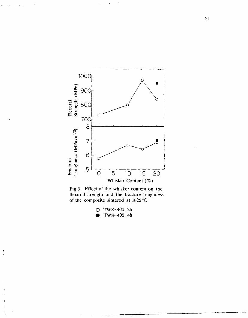
51
1000
S900
00= •800- 0
7008 1 1
S70~0
S6-
"0 5 10 15 20Whisker Content (%)
Fig.3 Effect of the whisker content on theflexural strength and the fracture toughnessof the composite sintered at 1825 °C
o TWS-400, 2h* TWS-400, 4h

52
INORGANIC FIBRES FOR CDMPOSITE MATERIALS
A.R. BUNSELL
Ecole Nationale Sup6rieure des Mines de Paris
Centre des Mat6riaux P.M. Fourt
B.P. 8791003 EVRY CEDEX FRANCE
Ceramic fibres of potential interest for reinforcement may be divided into fourvery 'different types. Those made by chemical vapour deposition onto a
substrate, those made by the conversion of a fine precursor fibre into a ceramic
fibre, continuous mono crystalline filaments and ceramic whiskers. The first
type of fibre has its origin in the early 1960's and is characterised by a large
diameter, usually between 100 and 140 tim, good mechanical properties but
inherent high cost. The boron and silicon carbide fibres made by the CVD
process have been produced on both tungsten and pitch based carbon fibre
cores and can be used to reinforce metals. Small diameter ceramic fibres beganto appear in the later 1970's with the development of the a-alumina fibre FP
from Du Pont. These fibres have diameters of around 20 Vm. It was the
development of fine diameter silicon silicon carbide based fibres by the
pyrolysis of polycarbosilane precursor fibres however which stimulated
research into reinforcing ceramics. These fibres have diameters generally
between 10 and 20 iim and result from research begun in the 1970's . The
Nicalon fibre produced by Nippon Carbon and which resulted from this
research first became commercially available around 1982. There now exists
several types of small diameter ceramic fibre which are candidates for
reinforcing ceramic matrices and their number is likely to increase. The Tyranno
fibre, produced several years after the launch of the Nicalon fibre by another
Japanese company, Ube Chemicals, is produced by a similar route but a small
amount of titanium in the structure gives it a slight temperature advantage as
well as inhibiting crystallisation.
The Nicalon and Tyranno fibres represent the first generation of small
diameter ceramic reinforcements which offered the possibility of reinforcing
ceramics and glasses. Both Nippon Carbon and Ube Chemicals have retained
the names of their fibres so that more recent fibres which represent a second

53
generation of reinforcements have the same names despite substantial changes
to their compositions, notably a reduction in oxygen. The presence of oxygenin the fibres is due to a crosslinking stage in the production of the precursorfilament which is usually achieved by heating in air. The latest versions of thesefibres which are not yet available outside Japan, are made from precursors
crosslinked by radiation.An alternative route for the production of ceramic fibres has been
adopted by a number of companies in Japan, U.S.A. and Europe. These fibresare made from polycarbosilazane precursors and produce fibres containing C, Siand N. The U.S. effort which was Federally funded brought together DowComing and Celanese which produced several fibres. The one which seems tobe being produced commercially is the HPZ fibre made by Dow Corning. Asimilar fibre was to be made by Rhone Poulenc in France but this work has beendiscontinued. Hoechst has developed such a fibre but is at a laboratory stage.
The only fibre which is said to possess an almost completely stochiometricstructure however is made by Tonen.. It should be noted that the Tonen fibre is
just becoming commercially available and it is claimed by the manufacturer thatthis silicon nitride fibre is stable in air up to 1400°C.
Some of the most stable materials when heated in air are oxides and sincethe production of the Fiber FP in the late seventies other fibres based onalumina have appeared. Du Pont produced PRD 166 which was an a -alumina
fibre partially stabilised with 20% wt zirconia. This fibre, like its predecessor,had an average grain size of 0.5 Vm, possessed a high Young's modulus and a
small strain to failure (0.5 %). Alumina based fibres have also been producedby Sumimoto Chemicals but in this case the fibres were microcrystalline andcontained 15 % of silica. The result was a drop in Young's modulus of nearly 50
% (200 GPa). The American company 3-M has produced a range of fibresbased on mullite called Nextel. The latest a-alumina fibre to appear is theA]max 10 pxn diameter fibre from Mitsui Mining.
All of the above mentioned alumina fibres are polycrystalline and arepromoted as being potential reinforcements for light alloys. All seem to berestricted to temperatures below 1200°C. This is because all phases of aluminaare converted to a-alumina at around this temperature or, in the presence of
silica, mullite is produced. Grain growth due to grain boundary diffusion occursat around 1200°C. and the fibres are seen to creep above 1000°C. None ofthese fibres retain sufficient strength above 1200'C to allow them to be used as

54,
a reinforcement however the fibres may be able to be used as refractoryinsulation to higher temperatures (1600 0 C).
Most of the problems with the small diameter oxide fibres and for thatmatter to some extent with the other small diameter ceramic fibres are linked tograin boundaries. The production of single crystal filaments is clearly one wayaround the difficulty and this philosophy has a parallel in the development ofmonocrystal superalloys. Such alumina fibres have been produced in the U.S.A.for nearly twenty years under the name of Saphikon and renewed interest isbeing shown for them. The fibre retains its properties at high temperature in away that the polycrystalline fibre do not however strength loss occurs at
discreet temperatures due to the cleavage of the crystal structure.Single crystal filaments are also found at the other extreme of fibre
diameters in the form of whiskers. These filaments generally possess diameters ofbetween 0.5 and 1.5 vrm with lengths from 20 IArm to 250 [.Lm however greater
lengths of several centimeters have been made in the USA and there are reportsthat whiskers having lengths of more than ten centimeters are available in the
former USSR.

55
INORGANIC FIBERS DIRECTLY FROM THE VAPOR PHASE.
FREDERICK T. WALLENBERGER*Du Pont Fibers, Experimental Station, P. 0. Box 80302, Wilmington, Delaware 19880-0302
PAUL C. NORDINEContainerless Processing Incorporated, 3453 Commercial Avenue, Northbrook, Illinois 60062
1. Introduction
We wish to report (1) a new generic process capable of making small diameter, strong
substrate-free inorganic fibers including carbon, boron, silicon, silicon carbide and silicon nitride
directly from the vapor phase (2) the effect of variables in this laser assisted chemical vapor
deposition, or for short LCVD, process on the properties of the resulting fibers using boron fibers
as the example of choice, and (3) early results with this LCVD process regarding other fibers.
2. Background
Several fiber-forming CVD processes a:e known. The best documented of these involves
the deposition of refractory compounds onto a heated metal or carbon filament. A commercial
bicomponent, boron/tungsten sheath/core fiber, for example, is made by this method for structural
composites applications by reducing boron trichloride in the presence of hydrogen to form a
deposit of boron on the heated tungsten wire. The fibers are continuous, but have large diameters.
Another fiber-forming CVD process, the metal catalyzed vapor-liquid-solid (VLS) process,
affords single crystal silicon carbide fibers. A hot liquid droplet of a metal alloy is the site for vapor
deposition and subsequent fiber growth. Fiber growth stops when the catalyst is exhausted. The
process is very slow and discontinuous and only very short fibers (often erroneously called
w%'hiskers) result. These fibers are among the strongest materials known.
* Present Address: University of Illinois at Urbana-Champaign, Department of Materials Scienceand Engineering, 204 Ceramics Building, 105 South Goodwin Avenue, Urbana, Illinois 61801

56
Laser assisted fiber processes are also known. The best documented is the laser heated
pedestal growth (LHPG) method. It uses a very large diameter, crystalline source rod and an annu-
arly symmetric laser beam. A molten float zone is created in the in the source rod. A seed rod is
introduced and slowly withdrawn to initiate the growth of sir.gle crystal fibers including sapphire
and other optical non-silica oxide fibers. Growth is slow; very small diameters are not attainable.
3. LCVD Fiber Process
Growth of strong, substrate-free, small diameter, fibers including carbon, boron, silicon,
silicon carbide and silicon nitride fibers, has now become possible by laser assisted chemical vapor
deposition (LCVD) at substantially higher rates than any other fiber forming laser assisted and/or
chemical vapor deposition process The LCVD process uses the focal point of a laser beam, rather
than the surface of a hot tungsten wire, or a hot molten catalyst droplet as the heat source to
decompose the gaseous reactants at above atmospheric pressures. The hot focal point of the laser
(Figure 1) is continually adjusted to coincide with the tip of the continuously growing fiber.
The boron deposition process and the resulting boron fiber were selected as the example of
chtcice to illustrate the new technology. The apparatus for growing the fibers consisted of an optical
bench with a continuous 5-watt Nd-YAG laser, a small reaction chamber in an enclosed laboratory
hood, a system for delivering the feed gases, a microscope attached to the reaction chamber to
observe and/or record the growth of individual fibers, and a computer to drive the gas supply,
deposition reaction, and fiber growth. A small reaction chamber was used as a research tool
suitable for producing, side-by-side, up to ten individual 1.4 cm long, <10 to >30 gim diameter
boron fiber specimens along the edge of a common substrate, e.g., a carbonized cardboard.
The small reaction chamber was found to facilitate an investigation where one process
variable (e.g., pressure, feed rate, pulling rate) was being changed in a given set of experiments,
while keeping all the others constant. An adaptation of this process made it possible to grow up to

57
2 meter long boron fiber specimens. In principle the process is capable of yielding endless fibers.
Specifically, pure boron fibers were grown from a gaseous mixture of 40% diborane and
60% hydrogen at temperatures ranging from 1000 to 1500K. The resultant fiber diameters ranged
from 9 to 100 gtm, but much smaller diameters are possible. The fiber diameters achieved in this
process are approximately equal to the diffraction limited laser focal spot size. The size of laser
focal spot is in turn dependent on the wavelength that the laser used.
4. LCVD Fiber Properties
The reactor pressure ranged from <100 to >1000 kPa, fiber growth rates from 0.1 to 1.0
mm/sec, and tensile strengths from < 3.0 to > 7.0 Gpa.. Tensile strength increased with increasing
reactor pressure. Strong fibers (>2.5 GPa) were readily obtained with high growth rates (>0.6
mm/sec) over a wide range of pressures. Ultra-strong (7.6 GPa), small diameter boron fibers were
obtained with growth rates of 0.5 to 0.6 mm/sec at the upper end of pressures used (1020 kPa).
The new boron fibers which were obtained by the LCVD process were x-ray amorphous
and had a smooth, uniform fiber surface. According to their absolute and specific tensile properties
(Table 1) they are stronger and stiffer than the other major composite reinforcing fibers which can
be made in the form of continuous fibers, i.e., boron/tungsten, IM carbon, and Nicalon* silicon
carbide fibers. Reinforcing fibers and composite parts are often used in weight sensitive appli-
cations. To reflect their value in this regard, tensile strength and modulus are expressed in terms of
specific strength and specific modulus (strength and modulus divided by weight density).
The LCVD boron fibers had >0.7x the average strength and modulus of single crystal VLS
SiC whiskers and >96% of the specific properties, but no continuous process is available for the
latter. As a result, they are among the strongest and stiffest inorganic fibers known. Early results
show that other materials which can be formed into small diameter fibers by laser assisted chemical

58
vapor deposition include carbon, silicon, silicon nitride, silicon carbide, germanium, and others.
The technology is expected to open up major new opportunities both in the non-silica optical fibers
market and the specialty structural fibers market.

59
TABLE I.Advanced Inorganic Fibers
Fiber Forming Processes Pure Boron Boron/W IM Carbon Nicalon*/SiC S. Cryst. SiCand Fiber Tensile Properties ibe Fibers Fibers Fibers Whiskers
Fiber Forming Process LCVD CVD PAN CARBOSILANE VLSProcess Capability continuous continuous continuous continuous discontinuousFiber Length, Demonstrated long (>2 m) endless endless endless short (4-2P -m)Fiber Diameter, rnii, Average 10 100 10 17 6
Tensile Strength, GPa 5.2 3.5 3.5 2.6 7.5 (28 mm,Strength, GPa (Best Sample) 7.6 5.1 4.1 3. 1 15.9 [4 mm)Tensile Modulus, GPa 400.0 400.0 280.0 190.0 578.0
Density, 3cm3 2.3 2.6 1.8 2.4 3.2Specific Strength, km 228.3 135.9 196.4 109.4 236.7Specific Modulus, 103 x km 17.6 15.5 15.7 8.0 18.2

60
Lens Focus-Substrate
F LFiber(h
Figure 1. Laser Fiber Grov, th (Schematically)

61
HIGH-PERFORMANCE BORON NITRIDE FIBERS FROMPOLY(BORAZINE) PRECERAMICS
Y. Kimura, Y. Kubo, and N. Hayashi
Department of Polymer Science and EngineeringKyoto Institute of Technology, Matsugasaki, Kyoto 606, Japan
Abstract
Boron nitride (BN) fiber was fabricated by utilizing an organic preceramics which wasobtained by thermal condensation of B,B,B-tri(methylamino)borazine (MAB) and 10 wt%of laurylamine (LA). The condensate, poly(aminoborazine), was melt-spun into thin fibersby an ordinary screw extruder. Its spinnability was excellent in spite of its low molecularweight (ca. 500), because the condensate consisted of planar borazine rings as the melt-spinnable carbon pitch is composed of fused aromatic rings. On spinning the fibersurface was hydrolyzed, and the fiber became infusible. The fiber was then pyrolyzed upto 10000 C in a flow of ammonia gas and was further sintered up to 18000 C in a nitrogenflow. The strength of the fiber was found to increase above 14000 C and to reach 1 GPa at18000 C. It was therefore suggested that the BN fiber is free from the degradation above14000 C where most ceramic fibers are known to lose their original strength.
1. INTRODUCTION
Much attention has recently been paid to hexagonal boron nitride (h-BN) becauseof its excellent thermal, mechanical and lubricating properties. One of the most strikingcharacteristics of h-BN may be small specific gravity (2.26) and low reactivity with metalsand ceramics relative to common ceramic materials. Therefore, h-BN can be utilized as areinforcing fiber and a coating for other ceramic fibers in fabricating fiber-metal and fiber-ceramic composites.
For the processing of h-BN fiber, however, the conventional thermal processescannot be utilized, because of its difficulty of melting and sintering. In early 1970s,Economy et al. invented a chemical conversion method to fabricate BN fiber in whichboron oxide fiber was converted to BN by solid phase nitridation in an ammoniaatmosphereI. In this process, however, the quality control of the precursor fiber ana theprocess control of the nitridation were not easy. Therefore, a new process calledpreceramic method has been developed, in which processable polymer precursors madeof the same elements with the desired ceramics are utilized. In this method the structureand properties of the precursor have close relation with the performance of the ceramicsobtained. Paciorek 2 , Paine 3 , and Sneddon 4 designed various derivatives ofpoly(aminoborazines) as the BN precursors, although these precursors could not beutilized for fiber spinning. In this paper we describe a new derivative of poly(borazine)which can be used as the precursor for fabricating BN fiber. It was readily prepared bythermal condensation of B,B,B-tri(methylamino)borazine (MAB). Since it wasthermoplastic, it was melt-spun into thin fiber by the conventional method. The fiber wasthen subjected to pyrolysis to obtain a high-performance BN fiber.

62
2. EXPERIMENTAL
2.1 MaterialsMethylamine (MA) and laurylamine (LA) were purified by distillation. B-
trichicroborazine (TCB) was prepared as reported previously 5 . TCB was reacted with anexcess of MA in toluene at room temperature. MAB was isolated as white waxy material(90% yield): IR (nujol) 3460 (NH), 1410 cm- 1 (B3N3 ring), etc.; 1 1 B NMR (C6D6)8 26ppm.
C1 NHCH 3NH3 I r.t. I
rt. II0*C N'BNH NH2 CH3 N BN"HBCI3 +NH 4 C1 - - 0 1\ I I-H~lC1 C 'l C1 -HC1 c B ,-N-B-c -BH B. NHCH3
C1 Ci1, N Ci NHCH3 N CHH H2.2 Condensation of MAB
About 20g of MAB and 10wt% of LA were placed in a 140ml tubular reactor fittedwith a three-way stopcock. The reactor was heated to 200-260'C for lh with the mixturevigorously stirred on a magnetic stirrer and with nitrogen gas introduced from one inlet of"•he three way cock. During the reaction MA gas evolved out of the system, and thecondensation product became gradually viscous. After the reaction, the product wasthoroughly dried in vacuo and analyzed by spectroscopies. 1H NMR (C6D6) 8 1.1 (t,CH3-C), 1.45 (s, C-CH2-C), 2.5 (m, CH3-N), 2.2-3.0 (broad, NH); 1 1 B NMR (C6D6) 8 26ppm.
2.3 Melt-spinningUsing a micro screw extruder with a nozzle of 500pm in diameter, the condensate
was melt-spun at 160-170 0 C. The extrudate from the spinneret was taken up by a winderto give a continuous filament of about 50pm in diameter.
2.4 PyrolysisSeveral pieces of the above filament (or powders) were placed on an alumina boat
and were immediately transferred to an electric tube furnace. The temperature of thefurnace was then raised to 600-1000"C at a rate of 100"C/hr in a flow of ammonia gas(30ml/min), held at the predetermined temperature for an hour, and cooled down to roomtemperature. The pyrolysates obtained were transferred to an alumina crucible and werefurther sintered at 1400 and 1800'C in a nitrogen flow. Their chemical and physicalproperties were characterized by diffuse-reflectance IR, WAXS, and densitymeasurements.
3. RESULTS AND DISCUSSION
3.1 Condensation of MABTable I shows some results of the thermal condensation of MAB in the presence of
10wt% LA. We had found before that the thermal condensation of MAB without additivesgave infusible products with poor spinnability because of the easy formation ofcrosslinks 6 . In the presence of LA the degree of condensation was successfullycontrolled, and colorless thermoplastic products were formed after weight losses of 10-20wt% due to the elimination of MA.

63
Table I Thermal condensation of MAB
Run No. LA Content Temp. Time Total Weight Loss Mn* Spinnability(wt%) ('C) (hr) (%)
1 10 200 1 10.1 -
2 10 220 1 13.4 - ZS3 10 240 1 17.1 470 04 10 260 1 18.6 - X
• Mw/Mn=1.75
The average molecular weight of thesoluble condensates were in the range of 500-800 as determined by GPC, which corresponds to NCH 3 NH
that of the pentamer or the hexamer of MAB. The . .
11B NMR spectrum of the condensates exhibited N NH HN NI I I L
a single peak at 5 26 ppm, which was identical H I. B.I I
with that of MAB. It suggested that the borazine N N N N NHR
rings of MAB were preserved in the condensates. B.N. B B, BTherefore, their structure is postulated as 1, in CH3 HN NH \ / NH NHR
which LA units are introduced as alkylimino H2 N NHCH3
chains or pendant alkylamino groups, by which 1the intermolecular crosslink can be controlled tomaintain the thermoplasticity of the product.
3.2 Thermal analyses of the MAB condensatesFig. 1 shows the
typical DTA and TG A 100
curves. The broadendothermic peak around so85 0C is due to the melting. ,The exothermic peakranging from 200 to 4300C060is ascribed to the furtherdecomposition of the 40condensate because it isaccompanied by the Iweight loss in TGA. At9000C, the weight lossbecame 38%, and a black . 0'
residue was obtained by W0 200 300 400 500 60 700 800 900
carbon ization of the Tcempcratur ('C)
organic groups. Fig. 1 DTA and TGA curves of MAB in nitrogen
3.3 Pyrolysis of the MAB condensateThe MAB condensate obtained at 240'C was directly pyrolyzed up to 600, 1000,
1400 and 1800'C. Some characteristics of the pyrolysates are shown in Table II. The
density increased with increasing the sintering temperature and reached 2.05g/cm 3 at
1800'C , which is slightly lower than the theoretical density of 2.26g/cm 3 for h-BN. Their
WAXS are shown in Fig. 2. As noted in the sharpening of the peak of (002) planes and its
shift toward the value 3.33A, the crystal lattice of h-BN grew gradually with increasing
temperature.

3.4 Melt spinning Table I1 Thermal conversion to ceramicsThe spinnability of the LA-
containing condensates was excellent in Temp. Time density d(002) colorspite of their low molecular weight. The ('C) (hr) (g/cm') (A)best melt-flow of the extrudate wasobtained for the condensate obtained at 600 1 1.73 3.72 yellow240'C (Run No.3). The good spinnability 1000 1 1.78 3.64 pale yellowis attributed to the planar structure of the 1400 1 1.91 3.50 greyoligomeric condensate, in which several 1800 1 2.05 3.39 whiteborazine rings are connected with eachother. This structure is comparable tothat of amorphous carbon pitch 7 which isutilized as the precursor of carbon fiber.The latter, having molecular weight of800-1000, consists of aromatic fusedrings in place of borazine networks.In these structures intermolecularaggregation force is so large that thespinnability is much improved. Fig.3shows a typical SEM micrograph of theprecursor fiber. The cross-section of thefiber was circular, and the inner phasewas homogeneous.
3.5 Sintering of fiberDuring the spinning the fiber
surface was slightly hydrolyzed to_ _ _ _.
become infusible. Therefore, the fiberwas directly sintered up to 10000C in anammonia gas flow without annealing of Fig. 2 WAXS of the MAB pyrolysatesthe fiber. In this stage the sintered fiberwas black due to the carbonization of theorganic residue. The fiber was furthersintered up to 18000C in a nitrogen flow.The color of the fiber turned brownish at Precursor12000C and became while above P '' :i'I
14000C. When the sintering up to
10000C had been done in a nitrogenflow, the color of the fiber remained blackeven though it was pyrolyzed up to18000C. This finding suggests that thepyrolysis in ammonia flow is effective forremoving organic residue and carboncontaminants. The fibers sintered at1000 and 14000C comprisedhomogeneous phases, while the one X450 1 00lmsintered at 18000C exhibited a slightgrain growth in its cross-section. Fig.3 SEM of precursor

65
3.6 Mechanical propertiesFig. 4 shows the changes in
tensile strength and modulus of the
fibers as a function of sintering .temperature. The modulus was * oincreased with increasing temperature, • __while the tensile strength decreased at 0/0
1400'C and increased again at the 0°
higher temperature. The highest tensile 2 _ _
strength and modulus were 0.98 GPa • "..and 78 GPa, respectively, which areeven higher than those of BN fiberreported before'. Most ceramic fibersprepared thus far are known to occurserious deterioration above 14000Cbecause of the abrupt crystallizationand coarse grain growth. The presentBN fiber is characterized by theexceptional increase in strength at 1, 1 X I,temperature higher than 1400"C. Ter:ature"C)
Fig.4 Changes in mechanical properties
References with sintering temperature
(1) J. Economy and R. V. Anderson, J. Polym. Sci., C19, 283 (1967)(2) K. J. L. Paciorek, D. H. Harris, and R. H. Kratzer, J. Polym. Sci., Polym. Chem. Ed. 24,173 (1986)(3) C. K. Narula, R. Schaeffer, and R. T. Pain, J. Am. Chem. Soc., 109, 55, 56 (1987)(4) P. J. Fazen, J. S. Beck, A. T. Lynch, E. E. Remsen, and L. G. Sneddon, Chem. Meter. 2,96 (1990)(5) Inorg. Synth., 13, 41 (1972)(6) Y.Kimura, N.Hayashi, H.Yamane and T.Kitao Proc. 1st Japan International SAMPESymposium, Nov. 28-Dec., p906, 1 (1989)(7) L. S. Singer, Carbon 16, 408 (1978)

66
SIMPLIFIED DYNAMIC FINITE ELEMENT PROCESSING MODEL FOR THECVD OF TiB, FIBERS
R. J. DiefendorfCeramic Engineering Department
Clemson UniversityClemson, SC 29634-0907, USA
and
L. MazloutAdvanced Innovative Technologies, Inc.
Troy, NY 12180, USA
Abstract
Titanium diboride appears to be an attractive candidate for ahigh temperature reinforcing fiber for intermetallic matrixcomposites. Titanium diboride has high modulus, reasonably lowdensity, a moderate thermal expansion coefficient and is thermo-dynamically compatible with a number of potential intermetallicmatrices. However, there is considerable disagreement in theliterature about its high temperature creep behavior. This workwas performed to prepare TiB2 fibers for evaluation of mechanicalbehavior using chemical vapor deposition. A simplified finiteelement, dynamic analysis model is used to describe the chemicalvapor deposition of titanium diboride fibers in a cold wall reactorat atmospheric pressure. The gas mixture considered is titaniumtetrachloride, boron trichloride, hydrogen, and hydrochloride. Adescription of the model and the computer program algcrithm andsubroutines are described. The application of this model to studythe effect of deposition parameters on TiB2 growth and the mecha-nism of rate limiting processes is discussed. For the mass trans-port rate limited process, the rate limiting mechanism changes fromexhaustion of BC1 3 and TiC] 4 at high dilution, t2 slow BC1 3 and TiCl 4diffusion at moderate concentrations, to slow HCI diffusion awayfrom the fiber surface at high reaction concentrations.

CREEP-RELATED LIMITATIONS OF CURRENT
POLYCRYSTALLINE CERAMIC FIBERS
JAMES A. DiCARLO
NASA LEWIS RESEARCH CENTER
CLEVELAND, OH 44135
ABSTRACT
For a thermostructural composite, it is desirable that the reinforcing
fibers display high stiffness (modulus) and high strength relative to the
matrix, and maintain these properties to as high a temperature as possible.
Among other benefits, this allows the composite to operate in the elastic
range to high stresses over a wide temperature range. For polymer and metal
matrix composites reinforced by currently available ceramic fibers, this
condition is genprally achieved up to the maximum use temperatures of these
composites. This is the case because use-limiting effects are typically
related to the mctrix (e.g., oxidation, plasticity) and occur at temperatures
lower than -800. where current ceramic fibers first begin to show significant
creep-related st ffness and strength degradation(I). For ceramic matrix
composites (CMC), however, this loss in fiber structural properties can occur
in the use temperature ranges projected for a variety of high performance
structural applications. Indeed, in some cases, current ceramic fibers show
stiffness and strength losses at temperatures well below those where similar
effects occur in potential ceramic matrices. At the present time, the
structural implications for these effects have not been fully comprehended,
either experimentally or theoretically. Clearly, critical questions arise as
to whether for any application above -800 0C, the creep-related change in

structural properties displayed by current ceramic fibers can be tolerated
and, if not, what minimum properties should be displayed.
The purpose of this paper is to present a status overview of the creep
properties, current limitations, and possible improvement approaches for those
polycrystalline ceramic fibers with current potential as reinforcement in high
temperature structural composites. This is accomplished first by a discussion
of how fiber creep influences the thermostructural service lives of composites
through such important engineering properties as dimensional stability,
strength stability, and failure behavior. Special emphasis is placed on CMC
and the key fiber properties that affect their high temperature reliability
(2,3). Because service life requirements vary widely from application to
application, generic property limitations are assumed for purposes of fiber
comparison. For example, for a dimensional stability requirement, a fiber
tensile creep strain of less than 1% is assumed for a constant service stress
of 100 Mpa. For a typical fiber Young's modulus of 200 Gpa, this imposes an
upper limit of 50 for NCS - cc/Ce = normalized creep strain. Here c, and Ce
are fiber tensile creep and elastic strains, respectively. However, arguments
are presented that suggest that when composite lives are limited by
maintenance of specific strength levels or avoidance of catastrophic failure,
NCS values much less than 50 will probably be required.
With this background in property requirements, the status and
performance issues for currently available fibers are then reviewed in terms
of their creep-related properties, such as creep, stress relaxation, and
stress rupture. Because of the general technical need for long-term
performance in oxidizing environments, focus is placed on two general
compositional classes: Si-based (e.g., SiC and Si 3N4) and A10 3 -based fibers.
In order to better elucidate creep issues and underlying mechanisms for these

69
fiber classes, they are further subdivided into generic types based on the
fiber fabrication approach, for example, chemical vapor deposition, polymer
pyrolysis, sintering, sol gel, etc.
To evaluate and compare the creep performance of each fiber type, some
recent advances in creep testing and modeling of polycrystalline ceramic
fibers are discussed (4,5,6). These advances center on a simple bend stress
relaxation (BSR) test (Fig.1). This test was developed at NASA because
literature data on fiber creep are scarce and because NCS values below 50
require accurate data in the primary creep stage, a region best evaluated by
stress relaxation measurements. It is shown that BSR data on both commercial
and developmental fibers can be used not only to indicate the time-temperature
conditions for the onset of strength degradation effects in each fiber type,
but also to compare and rank fibers in terms of their resistance to stress
relaxation (Figs. 2, 3). Also, using some simple basic assumptions, it is
shown that the BSR data can be converted to accurate predictions of tensile
creep strain as a function of time, temperature, and stress when the fibers
are subjected to constant stress and constant temperature conditions. This
tensile creep modeling in turn permits estimates to be made of upper use
temperatures for each fiber type for a givep service stress and life
requirement. Assuming a service life of 300 hours and an optimistic
requirement of NCS - 50, it is shown that currently available commercial Si-
based and A1203-based fibers can only attain upper use temperatures of about
1200 and 10000C, respectively (cf. Fig. 4). On the other hand, some
developmental fibers are shown to be approaching temperatures more desirable
for use in advanced CMC applications (Fig. 3).
Using basic materials engineering theory, suggestions are then offered
regarding microstructural alteration approaches that might be taken by each

70
fabrication method in order to produce polycrystalline fibers with optimum
creep resistance. These approaches are based on eliminating or minimizing the
underlying creep mechanisms operating in the various types of currently
available commercial fibers. Insight into these mechanisms is gained by
examining such factors as the creep activation energy which is directly
measured in the BSR test. The fact that some of the developmental fibers are
already taking microstructural steps in the right direction is discussed.
Finally, the paper is concluded with a brief discussion of the potential
temperature benefits to be gained if these improvements can be fully
implemented in polycrystalline ceramic fibers or if processing methods can be
developed for fabrication of more creep-resistant single crystal fibers (cf.
Fig. 4).
REFERENCES
I. DiCarlo, J. A.; "High Temperature Structural Fibers-Status and Needs,"presented at Fiber Producer Conference, Greenville, SC, May 6-9, 1991,NASA TM 105174.
2. DiCarlo, J. A.; "Fibers for Structurally Reliable Metal and CeramicComposites," J. of Metals, Vol. 37, No. 6, 1985, pp. 44-49.
3. DiCarlo, J. A.; "CMC's for the Long Run," Advanced Materials andProcesses, No. 6, 1989, pp. 41-44.
4. Morscher, G. N. and DiCarlo, J. A.; "A Simple Test for ThermomechanicalEvaluation of Ceramic Fibers," J. Am. Ceram. Soc., Vol. 75, No. 1, 1992,pp. 136-140.
5. Morscher, G. N. DiCarlo, J. A., and Wagner, T.; "Fiber Creep Evaluationby Stress Relaxation Measurements," Ceram. Eng. Sci. Proc., Vol. 12, No.7-8, 1991, pp. 1032-1038.
6. DiCarlo, J. A. and Morscher, G. N.; "Creep and Stress RelaxationModeling of Polycrystalline Ceramic Fibers," in Failure Mechanisms inHigh Temperature Composite Materials, ASME, AD-Vol. 22, AMD-Vol. 122,1991, pp. 15-22.

71
Initial Loop Unrestrained,
At Room Temp. Relaxed Fiber
HEAT /
TREAT aR a
(T,t)
m- 0/0 1 Ro/Ra
Graphite Graphite rodBlock _/
SRa
Ro • 4 or 8 mm
FIGURE 1. BEND STRESS RELAXATION TEST
TEMPERATURE, 0 C1700C 1500C 1400C 1300C 1200C 11ooC 1000C
1 HOURHEAT
S0.8 - TREATMENTSE IN ARGONs/s CARB.., DOW- 1 SCS-6- 66 NICALONR 0.6 -& MER CORNING /
E /L/A
A
R
T 042
04 4 5 5 5.5 6 6.5 7 7.5 8 8.5 9
I/TEMPERATURE(K) (-10-4)
FIGURE 2. TEMPERATURE -DEPENDENCE OF STRESS RELAXATION RATIO FOR SOME Si-BASED FIBERS

72
TYRANNO'-
NICALON 202-
SCS-6 -
LO-Ox NICALON _
HPZ-
TONEN_
DOW CORNING _-__
MERý-
CARBORUNDUM-
SiC WHISKER-
0 0.2 0.4 0.6 0.8
m
FIGURE 3. COMPARISON AND RANKING OF SOME Si-BASED FIBERS IN TERMS OFRESISTANCE TO CREEP-CONTROLLED STRESS RELAXATION
SIC-basedA120 3 -based
Current
Polycrystalline
Optimized
Current o
Single crystal
Optimized
500 1000 1500 2000
Use temperature, °C
FIGURE 4. ESTIMATES OF CREEP-LIMITED USE TEMPERATURES OF CURRENT FIBERS ANDNEW FIBERS WITH OPTIMIZED MICROSTRUCTURES. A DIMENSIONALSTABILITY LIMIT IS ASSUMED OF LESS THAN 1% CREEP STRAIN FOR 300HOURS AT 100 MPa.
73
-"AT 1-
L.1DMýI 113012 (IJL'!A)
1. Introd~uction
Advanice I co:npositas have acquirei the position of 'Tri:nieM"aterials" for miost of the critical al)?licatio-is in aero-spac3,Defence as well a3 Inlustrial sectors. The reinforcement fibrazfor such atrancej comf?osites m-aindlý are:
a) '"lass- fibres'b) ?3lyar~i4i4e frsan.1c) Car',on ?ib-r--s
,,.t of c:o fibres, bo-in'; light airost rafractorar,io.n?.'ete scaenario -;3cnailj Jieih th3 ;;ro~lct ap ýllca-.,io:n is at
`-is-oricalljf, first )a-tz~n on carbon fibres Jevelo?nent -...as,Lijf'act' ,il, o .aoo'-er 1 st,9 13 7. These car .bon' fibres of 7Z--isonwjere )rea3rai 'by pyrolysis of Celliose ani. were structurali1fweak
-ar eiawll as filaý.ients in electric 1iZh ubsutl nseffila~aaata cama into vojue. The carbon fibre was usB-I in electr----i c al
--,z late as 1)60 in :3 "?.v, :3ii.j~s bacaus e thed, wfmth stoal sh'iivibraýtibns b_-tttar thani t.;n~staa. T:le (3tructarallyr stro,16 ca-rb;onfibres '.!ere infact renetd urin ~ lae 0'Jo 1050. 'i a- tha~nt'iore h-avzo cieen aeruzefforts to =%ak carbon fibro3 wit.-h betteraund better meclianical properties.
2 .1a;.' Matria!s £'or Carb~on Fibres
Pro-- out of th3 lon, list of cunlilat aw materials, toiayr.~ i ~ ne f te ostpular and pr.z' recursor f'or t*:e variet7
of ..:e-ll. jua-lfiel reasý?ns likec hija carbon yiel-1, e."'ibitiona of?lasti~citj at- aro-xnd 130 09 a very stronj carbon bac-,-bone3 etc. etc.
7ia first brea': thro-i.]-i in the developaent of carrboni fibras.-:aZ troujit Out 'i~lanosyby Sin6in Ja-)n anI at et al.4in 7ro0yai Aircraft 7stalblishm~ent in U.K. It was soon estab.li sheia-t1at .uazlit; of ?M precursor ani o temperatUra ther.:-A3_
stubilisation con iition3 are - tw..o controlling'. fac tor3 for develooin,.Uhl Le:,'for.3iaice carbonl fibr3s from ? _ )raci.rsor.
'Ey all stanidardsl, Ja;)eanesa ?MPCl fibre iniustry has excelled1 in,ZM13ýn far su1;arior -acre'zors requirai for carboni fibr ez. Thdo
e;:Jinstia -:o -,:ination of japaaase carbon fib:re proluction the rlov~r(:Ko-- tot+l.~o d ,rol.uctio:i of ca:'bon- fibrao co.nes fro. 1 Ja,.2z±1

74
3.Develo,.ia.,jt of Carbon Fibres:
Followia~ - lo' dlia0 -ram su:,nar-isoas via ..aai. steps involvel inthe :anuiu.Cacture of carbon fibres, from PA 1.i:
0 A 9C D
PAN SAF OXIDATION PYROLYSI NEA TREATMENT_H ~ ~1400*C250
STABLIZED C.F C.F C.FPAN TYPE A TYPE 11 TYPE I
MAIN STEPS IN THE MANUFACTURE OF CARBON FIBER FROM PAN
T-s zeo~ most critical staep, after special precursor# 1;3 t~i-lo.i te..jarature sta-bilisastioniw-e~i tne Q)ea chain structarez of
io convertLel into la'Aer .) lym~ar which is associated wizh a lar,;a:te as sh~nin followin, reactions:
CH2 CH2 CM2 CH2CH CM
C ISO t C C~N 0 0 N N
I 11LII +AH
0ý0OC-:jD-k- NH
CYCLIZATION REACTION OF POLYACRYLONITRILE.
If this 3 ote. is not controllel it 16 liable to cauase Ida--e tOthe oni; .~i a 1 A stractu'e ani hence will resu.l-t in daeteriorationof carbon fibre properties. AiJlitionallj the qua-litj of thestabilised A fibre lepends on atleaast follourin.ý factors:
1. 'Lemparature of oxida-.,on.2. 'penzion -Avaa to th-3 fior).a towr
3. Tiija of oxilation4~. Aiabiant used
?. ate of heal'in--ý

2~'.J t~iJj.tj)A hal to t ~ j~i L,~oz r
of u-,, -=4to a.n ric~t!Dnz- -,i~ic' t*:, l~. T.
JiX2at ti,,uc~c': bo.i-o of t'i-- caai.-i. ~'o'ixzra:,z :i1 i:. to hava l010 cjclization, if' po~ssiýlet =- 11 o--Jdy 5 1iei-Aoeai~ of V~ic back. bono foc propor croz-- liný:4.1 reacti:oto 3czarL dunna.; pffjlysi-s a0 depictel balow*:
I'll IN I-"c 'o c %%
INTERMOLECULAR CROSS- LINKING OF OXIDIZED FIBERS THROUGH DEHYDROGENATION[FROM MANOCHA. L.M. AND BAHL.O0. P (1980). FIB. SCI. TECHNOL. 13,19 9)
_3. ;.jo.-j-i j_-u:onstura-ts howqc-.iae h slab' ist izit is o~lpo)r - -- e-., of tai_ ste., t'a
o .,i t.r.on j iro.t cane be
A,;ar2ý 1 siio.;.j neat flo., bei.viou~r of 1011. aŽian neatýe-' in a-rV_~e h C7Clisatio~i reactdoll is xtr1. in niature. Thie e:to
atartz ' aCýu 203 a ar~~. itzr'Y. 255 C. 4otof t.13 aat.i3.rz~ t:~e:~fore cun:1 01'. o~ci'llatio-' at t.~e~i~ oo .30
02 E A
U.
100 200 300 400
TEMPERATURE C-'
FIG. I. DSC CURVES OF PAN FIBERSA. IN PRESENCE OF AIR6. TN PRESENCE OF NITROGEN HEATING
RATE AtMIN

76
'.1Ž noAcc fro... thLz fi J~ t;'tit t'ier2 in a smaill o-icrc.~~'i1 120 owAi.oIyr~n ha.j redort3'.1y b3. iv~:~W 2.A~i.r i~~3t!.atoA~ ~e a-13 fo3r tho 0 !.r~j +~n~etv.A
o' ? * ~~lo.:.v~tvo reiction-. tn.'%, -A!-cn -.-'-vi ~ t~t.o
Hp OH OH H2 OH OHH HI H I H2
I I cH
+1/202- + H, 0
N N N N N N
REACTION-I
CHCKýHCH CH
I I I -2HCN 2Ný-CH-'4'N I N'L~JL.J CN
CNREACTION -2
ia in1tenzoioceiaar cro33li~n reactiox; introducB3 rIi mozss11 4_-i3 Str..ctura -13s~. th . -Ij:ra dation reactions introi =33s
a.~.it~on2.ra..:icitjin -asic Z., turo
fizorc s~ai2iiza Iu.) a secon!. naz-ia ~3o:eatiral. zAiffarantstructure ~ai a *-iolal h~as bean ?r3,.)aed to ex:,laiai the structurzdev.el0?.ns-nt. It is pertinenit to imantion here that suci stabilisalfibra3 can .be carbon!saei in a n~tter of' 1-2 :i&nat-n onily.,s com1?araf'
to5C~3miuts lpojal for nor..ial stabilissi PAI' filbre3. '.. hav--es4:-blfiShel tnat the libre stabilisatio rj ad1o~n b a roach6ives carbo~n fibris with ijaproved inechanica1 properties.
4. Post-sopirnnin .-ioliffication of PPA,' precursor
T'ie superior *yaies of ?ATI precursor davelopei by Japa xrnot.avi1&.eto othiers 1110 Wish to I3v10,) carboa fibrc..
*.r3,-.=3:). avail i3. 3I to oŽ.%er -'Ero,)oa~i c'rtiscoail~rlai couli l9--0 to c-ir:)- ,ilarer. with c3rt+w.'J.- Yoh0-1
D..- r' x3it not~ )033Oi*)!A to i,.r0V:o thaif~util; ofthe *;*racu=sor oullit;. kliitionS1.lj, UIreot 1
Ispealknca of Carboa fibra ztif.'n-3.3 (77' 10O) Cf) oni t-e ,)recurzo*r

77
28-.24-j20O
400 16-X 12-
4-
0-2 0-6 1.0 1-4Yp X1O PSi-a.
FIG. 2 RELATIONSHIP BETWEEN THE PRIMARY YOUNG'S
MODULUS OF THE RESULTING CARBON FIBRE ,Yc
~tu~~: -v;- tVier~for3 baeti to-o~ crj out thi i5ot-)LUv.D'.i-cations of suc', availa'jb33L~rt I~orv t'i car3- 1
in'77L -vie have- carrial out extensiv3 at.uliea on tho pracarzor
I) Ztratcc'aln i~ i prase 'ica of 0-411 13-nozic acid, D:., Ac tulc Aei
ItL n-a.j bý.-en posziý)le to io.iar taa -activatioa eaerj, ofcjrclizatbiol fro..2 nornial 130 *J/'Iole to about 100 K J/.,jolo. This
s:A.~3~et.;affacts t-ioj:intc o1' s a)ization sabsta-.itia1:.--
"0.7: fo 11 1d.rovC.e.1at. '.i is trn.iosi.3 ýr3vaaen-t i.1 4, 11~ .. Jit.~. :),.,Bvr ur-1.nlation of'ti procuuzor i..rva.t
an~v ca:*JO-1 fi.ýio jrooe-rties is quiita illtitel. D~etails '.;ill .)a
ii) T'eat-mant with aqcjuoua solution of ' 2n0D
KL-D 'ias been fo-mi to be verj exciting; piasticizer/catalyst.04= : conjugation has been confirmel throu:1i 17TIP~ analysis.
Thi-' tjoe of conj4u-tion hal?s are eas.! flog of the fibre -.Iitho-tre;isterin.; boni bra':,a~e etc-. Th3 activption eneri; of' cyclizc-tioa
coos loý.. to ?5 ~Jmole. . 0-100'. imýorove~iont in the t3n.Sile strn-th.-of carbon fibres has beaxi achievel as comoarel to the stranft', o--:
l~h~3:ifii. ~r~czsr. Str14 to) .7ail-ar of the carbnf.rs:ouT~o 1.7 to 12. Thi.s ti;cie.&Lj ie:onst-ýataz tvizt not 3.,'1y

78
vital Z-013 i-1 aet. i. e'foac '~; 'ITr.~
i~i) A-' na-.: t-,c~iLi-Au2 of' ;-3o3liiciti~oa u3in. *;o dif'fer-3.1t Ci2
catal;tic cju-liz-atio.1 has Wa~n eni)1oý'e1. The -.=-Dif'ici as e2as bi oiifl~-i '?r-cursors have beun characterizoi f'or thi~r:nschanicalt pij.ýicai and thermal behaviour .iuriný va-rious t 7of' ?rocessin,, to carbin fibres. Details will, be presantel.
3,roail; s,)ea~cin. tViera are thrae main obj ectivas to be 'liie.t:'.-roui~ procurso)r molif'ication. Those are3:
a) Thiririin.; of' the PA.1 fibres ani
6ia.3 t~ia ralat"ivqz vali,ez of' thi' car.~on f'ixaz
T.S Ga
Y. M
25 2 10 220G P 1-2%
UNMODIFED r7EMODIFIED
IMPROVEMENT IN THE CARBON FIBRE PROPERTIES OBTAINED THROUGHMODIFICATION OF THE PRECURSOR.
Yil 2e~riba iarxrou
for '3 coa~oi 4 .10 D e3cria -.. " b~ia 12.33.t-A vro. .

-79
C:) - :s - 2 ife s -n t 3-
0-
1-- PAN (C).
w
I'4
Lj.J .PAN (G)
LJ -MESOPHASE (C)mo I -PITCH (C)
u- PITCH (G)
I0 100 200 300 400 500 600 700 800 900 1000
FIBRE MODULUS, GPa
FIG. 3
1987 1996
29 MILLION LB 107 MILLION LB
AEROSPACE AEROSPACE 66
0THER
TRANS.~ ji~''22 .
RECREATIONAL OTHER231 TRANS 2 INDUSTRIAL 14
FORCAST CONSUMPTION OF ADVANCED
POLYMER COMPOSITES BY APPLICATION.
FIG. 4

80
SILICONIZING REACTION OF CARBON FIBRES
S.YAMADA,Dept.Mater.,Fac.Sci.& Engg..,Tne Nishi Tokyo Lniv.,Lenonara.Yamanashi 409-01 Japan.
E.YASLDA* ,Y.TANAB*, T.AKATSU* and M.SHIBLYA**.* Res.lnst.Engg.Mater.,Tokyo Inst.Tech.** Dept.Ind.Chem.,Fac.Engg..Tokai Univ.
I.Introduction
Recently it has been made clear that high performance carbonfibres(long length) are able to improve the fracture toughness cfceramic matrices basicallythrough a process of FW(filamentwinding)b / 2 using organic Si compounds.providing as high as over25 MPa.m of apparent KIC to Si 3 N4 . However, the poorresistivity vs. oxidation of carbon fibres limits the range ofits application obviously. In order to develop the ceramIccomposite for higher temperature uses such as ceramic eng:nebeing endurable at over 1300 0 C, the fibres also have to stand thesituation. For this purpose, sil iconizing reaction of carbonf bres to obtain SiC partia lly or tctal ly, was investigated.
II. Precursor
Both precu:rsors, a high modulus graphitized fibre(M-40 deliveredby Toray,a PAN-derivative) and an air-oxidized PAN, so-calledOXYPAN (del ivered by Toho Rayon), were employed;whi ie SiO and Siwere used as Si-sources.The fibres were put on the SiO or on Si1n a graphite crucible and heat-treated in a Tamman-typedgraphite oven at 1700 0 C under reduced pressures of -76,-50 and -
20 cmHg (gauge) , as well as normal pressure (0 cmHg gauge).-SiC formed was semi-quantitatively determined by XRD by using
ca i orat Io. curves.corresponding to both precursors. It also
means that the siliconized fibres are not amorphous as well-known SiC fibres such as Nicalon and Tirano-fibre bitpolycrystalline SiC.The reason why such reduced pressures werestudied, lay in the fact that the SiC whisker formation wasremarkably retarded by pressure, where the thicker whiskerformation by a siower crystallization could be realized.in. thiscase, SiC formation should be accelerated on the contrary. Theresult is as Illustrated in Figure 1.
A var ety of SEM observations showed that all of the OXYPAN-derivatives resulted in cracks in every filament:whereas Siprovided no smooth surface of the specimens derived from the bothprecursors.
III. Condition of the siliconizing reaction
Arrording to above mentioned result,M-40 and SiO were selected astne starting materials. Reaction temperatures were 1500,1600 and1700 0 C and pressures were the same as above.Figure 2 shows an
81
overview of carbon fibre(M-40) reacted with SiO under thesecondit ons.
Here it can be seen that only the product of reaction under -76c'Hg at every temperature shows very soft fibrous appearance.ThIs fact corresponds with the SEM observations as shown inFigure 3 for example, where only the specimens obtained under -76cmHg.not only in Fig.3(1600 0 C x Ih) but also in all the otherones obtained at 1500 and i700 0 C,showed " an incl necstructure".being obviously different from the others having adefinite boundary just like a sword and its sheath.
The formation mechanism of such an inclined structure should bemade clear, together with the mechanical strength of thus formeclong fibres, as well as the oxidation resistivity of them. it isnow being carried on.

Degree of vacuum vs. SiC content (SiO series)100
eoI[ CF(M40) +
S60S OSiD
g 4 Eoxypan +o Si0
S20
0
0 -20 -50 -76
Degree of vacuum (c.Hg)
Degree of vacuum vs. SiC content (Si0 series)
• ue 0 C MHg 2 0cmHg - 0 cmHg" .7 6 c mtIfg
h•, i v j rv iý4 of carbon fibers (•40) reacted with SiO
at various conditions,

83
EEC-)
~NJ L 2
S. 3A
Cd
u CD

THE DUAL NATURE OF VAPOUR GROWN CARBON FIBRES
Hans Jaeger and Tom BehrsingCSIRO Division of Materials Science and Technology
Locked Bag 33, CLAYTON, VIC 3168.
INTRODUCTION
Carbon fibres can be readily grown by exposing finely divided metals such asFe, Co or Ni on a support to hydrogen/ hydrocarbon mixtures at temperatures >=800*C. This causes a fraction of the metal particles to lift off the support producingbehind them, anchored to the substrate, cylindrical, hollow-core filaments withdiameters similar to those of the metal particles. These so called primary filamentsare progressively thickened to secondary fibres by deposition of carbon resultingfrom the pyrolysis of the hydrocarbon. Lengthening of the fibres ceases when themetal particle becomes covered with pyrolytic carbon 1,2
Previously little has been reported about the two stages of growth becauseunder conditions where visible fibres are produced the stages are concomitant thoughsuccessive for a given part of a fibre. However, it has been observed that near thehollow core of primary filaments 001 type planes are straight and parallel to thefilament axis3.
Here we show that the differences between primary filaments and secondaryfibres can be studied with electron microscopy when secondary fibres are fracturedor when the deposition of pyrolytic carbon is largely prevented. A theoreticalanalysis of diffraction patterns of primary filaments studied in this work has beenreported elsewhere4.
EXPERIMENTAL
The fibres were grown using A.R. grade ferric nitrate on alumina substratesattached to the end of a ceramic thermocouple sheath located in the centre of anexternally heated vertical alumina tube ( 19 mm i.d.). The reaction mixtures (natural gas, pure methane or A.R. Grade benzene and high purity hydrogen ) wereintroduced at the top of the tube. Benzene/hydrogen mixtures were produced bybubbling the latter through benzene (A.R. grade) at 6 - 25 *C. Other mixtures wereestablished using flow meters.
The substrates were wetted with 0.1 M ferric nitrate solution, dried in air atroom temperature and introduced into the reactor, which was purged with argonand heated to the reaction temperature (750 - 1150 °C) over a period of about 30min. For making fibres, which could be detected visually, selectedhydrocarbon/hydrogen mixtures were passed through the system for about 1 hour.The hydrogen was turned off and the hydrocarbon feed continued for another 5

85
minutes (thickening). Finally the system was purged with argon and the heatingturned off. For primary filaments the thickening was omitted. At the end of a runthe thermocouple and substrate were removed and the overall distribution, lengthand appearance of fibres examined with optical microscopy.
The samples were examined in a HITACHI S450-LB scanning electronmicroscope (SEM) fitted with a Traycor Northern energy dispersive X-rayspectrometer. The fibres were either left on the substrate or they were removed andattached to graphite supports.
Transmission electron microscopy (TEM) examination was carried out using aJEOL JEM 100-CX microscope operated at 100 kV. Samples of thickened fibres wereground lightly in ethanol and drops of the suspension placed on holey carbon filmssupported on Cu-grids.
Primary filaments were not visible with optical microscopy but they could bedetected by observing pieces of grit or soot which appeared to be suspended in midair. The filaments were collected by moving plain copper grids through the spacebetween the thermocouple sheath and the substrate or through gaps in the latter.
RESULTS
The growth and nature of fibres did not depend on the hydrocarbon used(methane, natural gas or benzene). However, the iron particles varied widely in sizeand became activated throughout an experiment. Therefore fibres varied widely inlength, and diameter, for the same temperature regime.
When the metal particles were small ( -10 nm across ) and the temperaturewas in the range 1000 - 1150 0C the morphology of the fibres was similar to thatreported generally in the literature. Observations on fibres broken in tension revealedthat the fibres had a dual nature. The bulk of a fibre was usually made up ofconcentric layers and occasionally the primary filament protruded like a "pig'stail" from the fracture face if the primary filament itself was ruptured; but extendedas a taut cord if it was still held by some obstacle outside the field of view. Oftenadjoining filaments appeared to have become fused during thickening.
When the diameter of a fibre exceeded -1 Ipm only the outer layers weretransparent to the electron beam in the TEM. Diffraction patterns taken from theseareas or from fibres which were thin enough to be transparent to the electron beamconsisted mainly of two broadened 001 type arcs normal to the fibre axis togetherwith very weak diffuse continuous hOO and hkO type rings ( Fig.la ). The appearanceof the patterns did not change if a fibre was rotated about its axis.
In TEM images primary filaments could also be seen to extend from fracturefaces of thick fibres. Usually only one but occasionally several primary filamentsextended from what appeared to be a circular single thick fibre. When the primaryfilament itself was fractured, it could be seen curled back, similar to the appearanceof broken primary filaments observed in the SEM. This is illustrated in Figure lb

86
which also shows that thin fragments of pyrolytic carbon were sometimes left aroundthe primary filament. These observations indicate that, at this point, the strength ofvapour-deposited fibres resides entirely in the primary filaments.
The primary filaments had hollow cores ( Fig. 2a ) and in diffraction patternsFig. 2b ) the 001 type reflections were very sharp and between them and the origin
was fine detail which varied with the inner diameters and tube walls of the filaments.In addition the hOO and hk0 type rings were broken into segments of spots with six-fold symmetry. These spots had distinct equatorial tails ( cf. Figs. la and 2b ). Thearrangement of segments around the rings show that in these primary fibres the 001type planes are parallel to the filament axis and that the carbon arrays in successivelayers are rotated with respect to each other.
Primary filaments which were not thickened were usually of uniform thicknessacross an entire TEM grid, 2.3 mm. These filaments were very flexible and wereoccasionally arranged in bundles which readily separated on bending ( Fig. 3a ).Diffraction patterns from individual filaments were the same as shown in Figure 2b.Patterns from a bundle ( Fig. 3b ) revealed that the 001, hOO and hkO type reflectionswere as expected from aligned individual fibres, but the fine detail between the 001type reflections and the origin was usually not resolved.
When the metal particles were large (>= 50 nm), intact fibres wereindistinguishable in the SEM from those having small leading iron particles.However, orientation of the 001 type planes relative to the fibre axis depended on thesize as well as on the shape of the leading particle. For spherical particles, diffractionrevealed that the 001 type planes in primary filaments were inclined to the filamentaxis. As a result these filaments broke readily. When the iron particles wereacicular the 001 type planes were aligned parallel to the filament axis. Irrespective ofthe orientation of 001 type planes in primary filaments, the pyrolytic outer material inthickened fibres was mainly aligned parallel to the fibre axis.
REFERENCES
G.G. Tibbetts, Vapour-grown carbon fibers, in J.L. Figueiredo et al. (eds.) CarbonFibers Filaments and Composites, Kluwer Acadiemic Publishers. Printed in theNetherlands, 1990. pp. 73-94.
2. R.T.K. Baker, Catalytic growth of carbon filaments, Carbon, 27, (1989) pp. 315-323.
. A. Oberlin, M. Endo, and T. Koyama, Filamentous growth of carbon throughbenzene decomposition, J. Cryst. Growth., 32 (1976) pp. 335-349.
"4. H. Jaeger, V.W. Maslen and A. McL. Mathieson, An analysis of electron diffractionpatterns of thin vapour-grown carbon filaments, Carbon, 30, (1992) pp. 269-284.

Figure 1:
a) TEM diffraction pattern of a thickened fibre (beam normal to fibre axis);b) TEM image of a broken thickened fibre; the primary filament, encircled by apiece of pyrolytic carbon, extends from the fracture face.
a)
b)

88
Fi2ure 2:
a) TEM image of a primary filament extending from the fracture face of athickened fibre; b) TEM diffraction pattern of the primary filament shown ina)(beamn normal to fibre axis).
a)
b50 nm
b)

Fi2ure 3:
a) TEN! image of a bundle of primary fibres; b) TEM diffraction pattern ofthe filament bundle; the arrow in a) points to the part of the bundle whichcontributes to the pattern (beam normal to fibre axis).
S 0.5 •
a)
b)
L0
90
GLASS FIBERS FROM HIGH AND LOW VISCOSITY OXIDE MELTS
FREDERICK T. WALLENBERGER*Du Pont Fibers, Experimental Station, P. 0. Box 80302, Wilmington, Delaware 19880-0302
SHERMAN D. BROWN
University of Illinois, Department of Materials Science and Engineering, Urbana, Illinois 61801
1. Introduction
We wish to report (1) an overview of four generic methods which were known in the
literature or de-veloped by us concerning the fabrication on non-silica or low-silica oxide glass fibers
from melts having viscosities at the liquidus ranging from <1 to >103 poise, (2) a mechanism we
recently proposed with regard to melt spinning of strong, oxide glass fibers from melts having low
viscosities at the liquidus, comparable to those of motor oil at room temperature, and (3) the potential
of aluminate and te~lurite fibers made by one of these fiber-forming methods as new infrared optical
fibers, especially for the infrared range above 3 Iim.
2. Background
In the field of alumina-based optical fibers attention has only been paid to single crystal
sapphire fibers for special premium applications, but none to optical non- or low-silica glass fibers.
Fabrication of sapphire fibers is based on a very slow process, and the cost of the product is very
high. However, calcium aluminate bulk glasses are known to have sapphire-like infrared
transmission spectra, and if the correspon-ding fibers were made by a modem melt processing
method, they might be less costly and still effective.
* Present Address: University of Illinois at Urbana-Champaign, Department of Materials Scienceand Engineering, 204 Ceramics Building, 105 South Goodwin Avenue, Urbana, Illinois 61801

91
Surprisingly, many calcium aluminate glass fibers with 30-80% alumina were experimentally
made and evaluated by several groups before 1970 for structural, but not optical, uses. Research was
aimed at identifying compositions of alumina-based fibers having a higher modulus than S-glass, the
highest modulus of any silica-based fiber then on record, excluding HM-glass containing toxic
beryllia. New high modulus aluminate fibers were identified but none was commercialized.
The excellent work that was done between 1950 and 1970 is accessible, but not readily. It is
recorded in a series of unclassified reports to several government agencies. Only one publication
appeared in a refereed journal, and deals with fiber formation and glass fiber properties. It is an
authoritative source but it is not readily accessible for a different reason; it does not use the word
"fibers" in its title or abstract. No theoretical analysis was provided relating composition to viscosity
and glass formation, or composition and glass fiber modulus. Interpretations were given for various
phenomena, but our analysis shows they are not predictive.
3. Generic Fiber Processes
Onoda and Brown [1970] showed that there is a region -45% alumina and <5% alumina in
the calcia-alumina-silica phase diagram with very high melt viscosities (>103 poise), while the
remaining compositions have very low melt viscosities (<5 poise). Wallenberger, Brown, et al.
[19921 proposed that (1) calcium alu-minate glass fibers are better suited for IR optical. than for
structural uses, and can be made by one of four generic melt processes as shown in Figure 1, and (2)
selection of a preferred process for a given composition depends only on its viscosity at the operating
temperature, where it should be -103 poise as for silicate fibers.
Machlan [1955] was able to identify one out of thousand experimental, quaternary. low
silica compositions as having a sufficiently high viscosity above the liquidus to obtain glass fibers by
spinning them through an orifice. The melt viscosity was not reported but the melt must have been

92
102 -103 poise above the liquidus like a silicate melt. In summary, even the highest viscosities in the
alumina system are lower than those in the silica system and it is not likely that this fabrication
method will be useful in the alumina system.
Onoda and Brown [1970] were able to identify about sixty out of three hundred
experimental, quaternary and ternary, low-silica compositions with 40-50% alumina and .c5%
alumina having fiber forming viscosities (102 -103 poise) below the liquidus. The authors did
measure the viscosity as a function of tempe-rature. Glass fibers were only obtained from selected
compositions by up-drawing from the surface of super-cooled melts, and a continuous process was
developed for structural, single component fibers, but not com-mercialized. In summary, a process
is available but it is difficult to fabricate clad optical fibers by this route.
Wallenberger, Weston and Brown [19911 reevaluated up-drawing from supercooled melts,
and made glass fibers from a quaternary non-silica composition with 46% alumina and a quaternary
low silica compo-sition with 42% alumina. They also succeeded in down-drawing both composition
from the preforms evident-ly have fiber-forming viscosities (102 -103 poise) at, but not above, the
liquidus. In summary, silica is not required as a viscosity builder (network former) and down-
drawing of fibers from a preform might become the method of choice for fibers previously up drawn
from supercooled melts. Also, clad optical fibers are more readily made by down-drawing from a
preform than by up-drawing process frm a supercooled melt.
The vast majority of glass fibers, especially those with 50-80% alumina have low melt
viscosities (<5 poise) and can only be made by inviscid melt spinning, a process whereby a low
viscosity jet is ejected into propane, a chemically reactive medium. The pyrolytic decomposition of
propane stabilizes thý. molten jet. The consolidated fiber has a carbon-rich skin. Wallenberger et al
[1992] reported that the operative mechanism is rheology-dominated. Incorporation of particulate
carbon into the skin of the jet increases its surface viscosity, prevents break-up into Rayleigh waves

93
and droplets, and facilitates melt spinning of continuous filaments. Carbon may ultimately not be a
suitable surface stabilizer for optical fibers; others are being explored.
4. Infrared Optical Fibers
Wallenberger et al. [1991] reported the infrared transmission of calcium aluminate glass
fibers to be identical with those of comparable commercial bulk glasses. The new glass fibers, like
similar bulk glasses, have sapphire-like infrared transmission (Figure 2), thus potential for becoming
a high volume commodity product. Wallenberger, Weston and Brown [1992] also reported the
successful fabrication of tellunte (telluria-alumina) glass fibers by up-drawing from supercooled
melts. In summary, the exploration of optical non-silica oxide glass fibers by an appropriate generic
process is now open to exploration.

94
Pretorm
RingHeater
Fiber
W~ndLp
0 Wmrdup
WVindup nert Gas
P opane Propane
Fber -- 4-
Fiber
0 W,ndup
Figure 1. Generic Fiber Processes:Melt Spinning through an Orifice (top, left), Up-drawking from a Supercooled Melt (bottom, !ct!,.Down-drawing from,, Preform (top, right),& Melt Spinning from an Inviscid Melt (bottom r -t

95
100-90-
00 70-- "
0 60-
-50-
40-"•-30-
20-10 0
00
0 1 2 3 4 5 6 7
Wavelength, lum
- Ca Aluminate - Sapphire .. . Quartz
Figure 2. Sapphire and Saphire-like Infrared Transmission