Advances in Alkaline water electrolyzers: A revie · 2 production, electrolysis high-light because...
54
Advances in Alkaline water electrolyzers: A review Martin David a,b,c,* , Carlos Ocampo-Martinez c , Ricardo Sanchez-Pe ˜ na a,b a Instituto Tecnol´ ogico Buenos Aires, Ciudad Aut´ onoma de Buenos Aires, Argentina b Consejo Nacional de Investigaciones Cient´ ıficas y T´ ecnicas (CONICET), Ciudad Aut´ onoma de Buenos Aires, Argentina c Automatic Control Department, Universitat Polit` ecnica de Catalunya, Institut de Rob ` otica i Inform` atica Industrial (CSIC-UPC), Barcelona, Espa˜ na Abstract The renewed concern for the care of the environment has led to lower emissions of greenhouse gases without sacrificing modern comforts. Widespread proposal focuses on energy produced from renewable sources and its subsequent storage and transportation based on hydrogen. Currently, this gas applies to the chemical industry and its production is based on fossil fuels. The introduction of this energy vector requires the development of environmental-friendly methods for obtaining it. In this paper, existing techniques are just presented and the main focus is made on electrolysis, a mature procedure. In turn, some developed proposals as previous steps to the hydrogen economy are presented. Finally, some lines of research to improve alkaline electrolysis technology are commented. Keywords: Hydrogen economy, hydrogen production, electrolysis * Corresponding author Email address: [email protected] (Martin David ) Preprint submitted to Renewable and Sustainable Energy Reviews 1st March 2019
Transcript of Advances in Alkaline water electrolyzers: A revie · 2 production, electrolysis high-light because...

Advances in Alkaline water electrolyzers: A review
Martin Davida,b,c,∗, Carlos Ocampo-Martinezc, Ricardo Sanchez-Penaa,b
aInstituto Tecnologico Buenos Aires, Ciudad Autonoma de Buenos Aires, ArgentinabConsejo Nacional de Investigaciones Cientıficas y Tecnicas (CONICET), Ciudad Autonoma de
Buenos Aires, ArgentinacAutomatic Control Department, Universitat Politecnica de Catalunya, Institut de Robotica i
Informatica Industrial (CSIC-UPC), Barcelona, Espana
Abstract
The renewed concern for the care of the environment has led to lower emissions
of greenhouse gases without sacrificing modern comforts. Widespread proposal
focuses on energy produced from renewable sources and its subsequent storage
and transportation based on hydrogen. Currently, this gas applies to the chemical
industry and its production is based on fossil fuels. The introduction of this energy
vector requires the development of environmental-friendly methods for obtaining
it. In this paper, existing techniques are just presented and the main focus is made
on electrolysis, a mature procedure. In turn, some developed proposals as previous
steps to the hydrogen economy are presented. Finally, some lines of research to
improve alkaline electrolysis technology are commented.
Keywords:
Hydrogen economy, hydrogen production, electrolysis
∗Corresponding authorEmail address: [email protected] (Martin David )
Preprint submitted to Renewable and Sustainable Energy Reviews 1st March 2019

1. Introduction
The world economy is constantly expanding. There are two influencing factors
related to that expansion: the population growth and progress in personal comfort.
Both factors affect the current fossil economy by increasing consumption and
generating greater amount of greenhouse gases (GHG). The International Energy
Agency (IEA) indicates a world consumption in 2015 of 9.383 Mtoe (1.1×10⁵
TWh). This amount represents an increase of 18,23% and 99.64% over the past
ten (2005) and fourty (1975) years, respectively. Besides, CO2 emissions in 2015
were 32.294 MTon, compared to 15.484 MTon in 1975 (109% increment) [1].
This situation is widely accepted as critical, hence worldwide environmental im-
pact studies and environmental protection policies are generated. Moreover, the
fact that fossil fuels are neither renewable nor evenly distributed across the globe
leads to geopolitical conflicts and unequal situations.
Around the world, proposed solutions focus on the production of renewable
energy. However, the share of renewable energies has not grown significantly
(from 12.7% in 1975 to 13.5% in 2015). Besides costs issues, the global exper-
ience indicates that advances are needed to solve technical problems related to
energy fluctuations produced in renewable sources. To achieve high integration of
renewable energy, it is necessary to have the ability to accumulate the excess of
energy to be consumed at a time when consumption exceeds production. Figure 1
shows the variety of available technologies for energy storage. While some tech-
nologies such as supercapacitors or flywheels are used to store a reduced amount
of power (up to 10MW) for a short time (up to an hour) and redeliver it quickly,
for the case raised, it is necessary to use other technologies such as Compressed
Air Energy Storage (CAES), Pumped Hydro Energy Storage (PHES) or hydrogen.
2

Figure 1: Current energy storage methods (taken from [2]). 1SMES: Superconducting Magnetic
Energy Storage, 2PHES: Pumped Hydro Energy Storage
So far, the most common way to store large amounts of energy is PHES. The
biggest disadvantage of this technology is related to its requirements on specific
geographical features for installation and political conditions. It is here that among
the methods of energy storage, hydrogen production currently takes relevance for
its energy density, high energy capacity and transportability [2, 3].
Moreover, in the same direction, there is the concern about pollution in the
transportation sector. Along with the development of electric vehicles, the hy-
drogen appears as an interesting energy vector. Both technologies, electric and
H2-based vehicles, share the benefit of eliminating urban pollution and, depend-
ing on the original source, reducing or eliminating pollution in the whole process
[4]. The union of these two sectors, electricity and transport, generates what is
disclosed as hydrogen economy. The hydrogen economy is stated as an integral
solution for the problem of producing, storing and supplying energy including all
3

final uses while succeeding in GHG mitigation.
The industrial use of hydrogen dates from almost a century ago with a wide
consumption in the chemical and oil industries (89% of consumption share) [5].
However, progress must be achieved in various issues in order to accomplish com-
petitiveness of these technologies and develop this economic concept. Issues such
as the efficiency and cost of production, storage and transport, are concepts that
several companies, research centers and governments are developing.
Several reviews can be found that present the different technologies related to
the use of hydrogen. Abdalla et al [6] published a review of hydrogen technologies
making a detailed explanation and comparison of current storage methods. Zhang
et al [7] present a brief and well-organized compendium of production, storage
and electricity generation technologies. Dutta [8] summarizes development mod-
els for the hydrogen economy in various countries along with an explanation of
hydrogen production, storage and utilization. Mazloomi and Gomes [9] discuss
the economic aspects of centralized and distributed production. In addition, they
present the risks inherent in the production, storage and distribution stages, pro-
posing possible risk-reduction techniques.
At the same time, there are studies such as [10] that detail the steps to be
followed in order to reach a mature hydrogen economy. Among those steps there
are the Power-to-Gas [11, 12], the use of fossil hydrogen to power vehicles [13, 14,
15, 16] and the integration of electrolyzers with renewable energies in microgrids
[17, 18]. All these developments bring hydrogen technologies taking into account
the necessary economic issues in order for it to be sustainable over time. To
do this, it will be necessary that companies, governments and research centers
cooperate together in this direction [13].
4

This paper provides an overview of the hydrogen production technologies,
specifically emphasizing production from alkaline electrolysis. Mueller-Langer
et al [19] in their techno-economic assessment assure that natural gas steam re-
forming, coal and biomass gasification and water electrolysis will play a signific-
ant role in the short and medium term. Besides, electrolysis occupies until today
a dominant position as it is the only technology that can use directly the power
surplus from renewable and fluctuating energies like wind mills or solar panels
[7] so it has a concrete perspective on the use of this type of energy as the axis
of the hydrogen economy. Among CO2-neutral H2 production, electrolysis high-
light because it produces high purity hydrogen and it has an infrastructure already
developed being a well-established technology [20, 21]. In the same direction,
alkaline electrolysis is a mature and reliable technology which stands out from
other types of electrolysis based on cost and simplicity [22].
The remainder of this paper is organized as follows. In Section 2, hydrogen
production technologies are compared according to efficiency, costs and envir-
onmental consequences. After that, in Section 3, water electrolysis, as the most
certain solution for ecofriendly hydrogen production, is described. Then, in Sec-
tion 4, necessary developments in alkaline electrolyzers in the short and long term
are displayed. Finally, conclusions in Section 6 reinforce the necessity to advance
research to achieve the reduction of pollution through the hydrogen economy.
Figure 2 shows the different methods of hydrogen production presented in
Section 2. It highlights the approach outlined in this paper, explaining its organ-
ization.
5

Hydrogen production methods
Hydrocarbons Other feedstockBiomass Water
Steam reforming
Partial oxidation
Autothermal reforming
Plasma reforming
Dark fermentation
Microbial electrolysis
Photo fermentation
Biomass gasification
cell
Ammonia reforming
Electrolysis
Thermochemical water
Photolysis
splitting
water splitting
Photoelectrochemical
reforming
Aqueous phase
Alkaline electrolyzer
PEM electrolyzer
SOE electrolyzer
AEM electrolyzer
Figure 2: Taxonomy of hydrogen production with emphasis in this paper’s objective (in boldface)
2. Hydrogen production methods
There are several methods of hydrogen production with different stages of de-
velopment. Currently, its production is mainly based on the reforming of fossil
fuels (78%) and coal gasification (18%). From the pending 4% of alternate re-
sources, the main technology is the electrolysis of water as a byproduct from
chlor-alkali process [23, 24]. Despite the current use of hydrogen produced by the
last process, this technology will not be considered in the analysis because in the
long term and taking into account the amount of hydrogen necessary, it would not
be sustainable due to the chlorine produced at the same time.
In addition to the named technologies, in Table 1 it can be seen the selection
offered by Holladay et al. [25] covering industrial methods and those which are
being developed.
Some of the parameters used to compare different methods of hydrogen pro-
6
duction are efficiency, cost and environmental consequences. Efficiency, overall,
compares the energy provided by the one obtained as the Lower Heating Value
(LHV) of H2 produced, whose ranges are listed in Table 1.
Moreover, the economic cost has the difficulty of analyzing mature technolo-
gies such as the steam methane reforming (SMR) with newly developed methods
on a laboratory scale as photolysis. In turn, the technologies that rely on fossil
fuels have different costs in case carbon capture and storage (CCS) approaches are
considered or not. For instance, Parthasarathy and Narayanan [38] present SMR
and coal gasification as the cheapest options (0.75 U$Skg−1 and 0.92 U$Skg−1 of
H2 produced, both without CO2 capture) while electrolysis, considering the pro-
duction of electricity with nuclear energy, costs between 2.56 U$Skg−1 and 2.97
U$Skg−1.
Besides, Hosseini et al [39] present a cost comparison between some produc-
tion methods as can be seen in Table 2. Production from fossil fuels was shown to
be cheaper, even if CCS were required. Levene et al [40] consider that electricity
costs have a great influence on the price of hydrogen produced by electrolysis, so
it is concluded that the cost of electricity must be four times lower than the current
price to have a competitive solution using solar and wind energy.
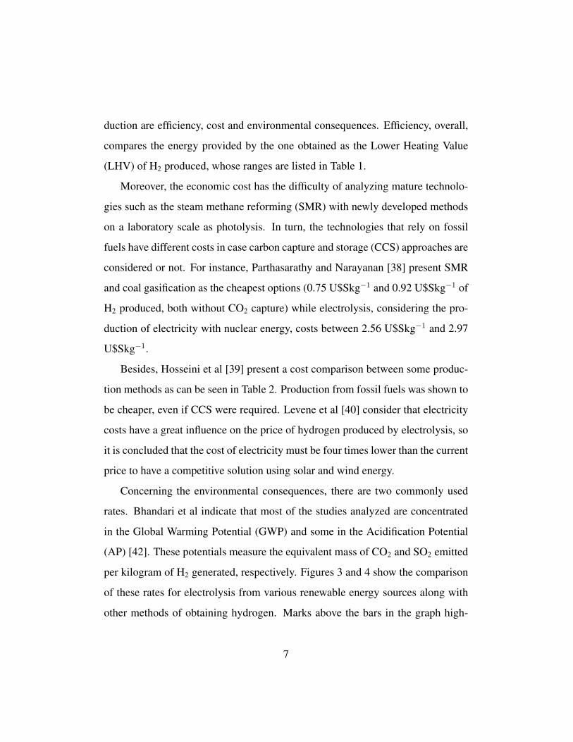
Concerning the environmental consequences, there are two commonly used
rates. Bhandari et al indicate that most of the studies analyzed are concentrated
in the Global Warming Potential (GWP) and some in the Acidification Potential
(AP) [42]. These potentials measure the equivalent mass of CO2 and SO2 emitted
per kilogram of H2 generated, respectively. Figures 3 and 4 show the comparison
of these rates for electrolysis from various renewable energy sources along with
other methods of obtaining hydrogen. Marks above the bars in the graph high-
7

Table 1: Summary of methods for obtaining H2 (adapted from [25])
Technology Energy source Feedstock Efficiency Maturity Reference
Steam reforming Thermal Hydrocarbons 70-85% a Commercial [26]
Partial oxidation Thermal Hydrocarbons 60-75% a Commercial [26]
Autothermal reforming Thermal Hydrocarbons 60-75% a Near term [26]
Plasma reforming Electric Hydrocarbons 9-85% b Long term [27]
Aqueous phase reforming Thermal Carbohydrates 35-55% a Mid term [28]
Ammonia reforming Thermal Ammonia NA c Near term -
Biomass gasification Thermal Biomass 35-50% a Commercial [29, 30, 31]
Photolysis Solar Water 0.5% d Long term [32]
Dark fermentation Biochemical Biomass 60-80% e Long term [29, 33]
Photo fermentation Solar Biomass 0.1% f Long term [29, 30]
Microbial electrolysis cell Electric Biomass 78% g Long term [34]
Alkaline electrolyzer Electric Water 50-60% h Commercial [30, 35]
PEM electrolyzer Electric Water 55-70% h Commercial [30, 35, 36]
Solid oxide electrolysis cell Electric+Thermal Water 40-60% i Mid term [31]
Thermochemical water splitting Thermal Water NA c Long term -
Photoelectrochemical water splitting Solar Water 12.4% d Long term [35, 37]
aThermal efficiency, based on the Higher Heating Values (HHV)bBased on efficiency equation from [27]cNot availabledSolar to hydrogen via water splitting and does not include hydrogen purificationePercent of 4 mol H2 per mole glucose theoretical maximumfSolar to hydrogen via organic materials and does not include hydrogen purificationgOverall energy efficiency including the applied voltage and energy in the substrate. It does
not include hydrogen purificationhLower heating value of hydrogen produced divided by the electrical energy to the electrolysis
celliHigh-temperature electrolysis efficiency is dependent on the temperature the electrolyzer op-
erates at and the efficiency of the thermal energy source. If thermal energy input is ignored,
efficiencies up to 90% have been reported [31].
8

Table 2: Cost of hydrogen production methods (from [39])
Process Cost of H2 (USDkg−1)
Natural gas reforming 1.03
Natural gas reforming + CCS 1.22
Natural gas reforming + PSA + CCS a 1.56
Coal gasification 0.96
Coal gasification + CCS 1.03
Wind electrolysis b 6.64
Biomass gasification 4.63
Biomass pyrolisis 3.80
Nuclear thermal splitting of water 1.63
Gasoline (for comparison purposes) 0.93
aCurrent central H2 production from Natural Gas with Pressure Swing Adsortion (PSA) used
for H2 purification up to 99.6% [41]bElectrolysis using electricity generated by wind turbines
9

lights the different GWP values extracted by Bhandari et al from their sources
[42]. It must be emphasized that these studies are based on Life Cycle Assessment
(LCA), which comprises the construction, operation and end of cycle of each tech-
nology. It can be seen that electrolysis together with renewable sources produces
less pollution than widely used technologies, even in cases of considering CCS.
Although thermal decomposition has better results, it still needs to be developed.
Besides, biomass gasification is slightly more polluting than electrolysis but it is
a technology that also receives interest today.
Based on the previous study, Dincer and Acar [43] present an analysis com-
paring various technologies based on sustainability and costs. It is necessary to
clarify that for the calculation of the environmental impact of electrolysis, these
authors took the average value of all sources of electricity, including the grid.
Therefore, due to the fact that the electricity network has higher polluting emis-
sions, the GWP value of electrolysis appears as a non ecofriendly method. This
is not the case when electrolysis is combined with renewable sources, as will be
considered in this work.
While the electrolysis was the first commercial method of obtaining hydrogen
[42], other methods such as SMR have taken its place and are today the processes
used at industrial level because of their better efficiency and costs. However,
facing the new optical of environment care and GHG emissions mitigation, elec-
trolysis takes back relevance and the research is aimed at improving those two
aspects.
Moreover, there are various methods of producing hydrogen which are eco-
friendly and competitive. Currently, there is a strong research on the use of bio-
mass, which is accepted as the substitute for the use of fossil resources [39]. How-
10
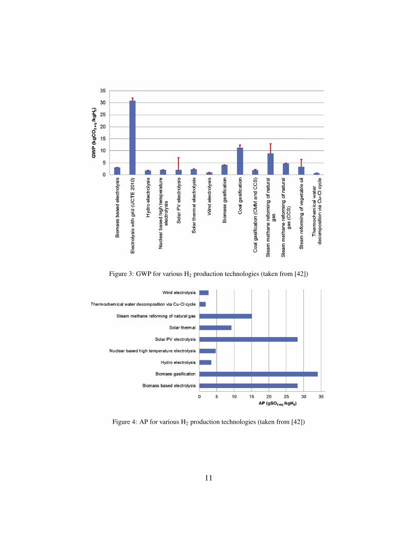
Figure 3: GWP for various H2 production technologies (taken from [42])
Figure 4: AP for various H2 production technologies (taken from [42])
11
ever, these technologies require different levels of development and scalability
testing, but promise to be competitive [20]. Among them, it is worth mentioning
the case of microbial electrolysis, since it can achieve a high efficiency in the pro-
duction of hydrogen and is considered versatile in terms of the various alternatives
of application [44].
As stated in Section 1, electrolysis has the ability to take direct advantage of
the surplus electricity from renewable energy sources that is a fundamental step in
the development of the hydrogen economy. So from now on, this paper will focus
on this technology.
3. Water electrolysis
Electrolysis is the method through which the water molecule is separated into
hydrogen and oxygen by applying an electric current [42]. Although there are dif-
ferent methods, which are introduced below, they share the same global reaction
H2O(l) −−→ H2(g) +1
2O2(g).
3.1. Alkaline electrolysis
Alkaline electrolysis highlights among other technologies since it is the one
with greater maturity and the larger commercial outreach [43]. The system is con-
stituted by a pair of electrodes immersed in an alkaline solution, usually potassium
hydroxide (KOH) at a concentration of 25 to 30%, and separated by a diaphragm.
At the cathode water is split to form H2 and releasing hydroxide anions which
pass through the diaphragm and recombine at the anode to form O2 according to
the following reactions:
12

2 H2O(l) + 2 e− −−→ H2(g) + 2 OH−(aq),
2 OH−(aq) −−→ 1
2O2(g) + 2 e− + H2O.
3.2. Proton Exchange Membrane electrolysis
The electrolyte in this case is a polymeric membrane with acidic nature that
allows exchange of protons (H+), hence its name Proton Exchange Membrane
(PEM). That membrane, along with the electrodes, form what is called Membrane
Electrode Assembly (MEA). At the anode, water is oxidized to O2 and release
protons that flow through the membrane and are reduced at the cathode to form
H2 according to the following reactions [45]:
H2O(l) −−→ 1
2O2(g) + 2 H+(aq) + 2 e−,
2 H+(aq) + 2 e− −−→ H2(g).
3.3. Solid Oxide Electrolysis (SOE)
Both Alkaline and PEM electrolyzers are known as Low Temperature Electro-
lyzers (LTE). On the other hand, a third option, Solid oxide Electrolyzer (SOE),
is known as High Temperature Electrolyzer (HTE). Although LTE is a mature
technology, HTE has the distinction of performing electrolysis of water vapor at
high temperatures, resulting in higher efficiencies compared to previous options.
Moreover, it has the possibility of using waste heat instead of part of the elec-
tricity needed [46, 47]. Despite this, they are not ready to be commercialized
because they have durability problems due to the severe conditions. The reactions
occurring at the cathode and anode are as follows:
13

H2O(g) + 2 e− −−→ H2(g) + O2−,
O2− −−→ 1
2O2(g) + 2 e−.
3.4. Anion Exchange Membrane electrolysis (AEM)
A technology that is being developed is the cell with Anion Exchange Mem-
brane (AEM). Schematically it has the same structure of a PEM cell with the
difference that the membrane transports anions OH– instead of protons H+ . In
that sense, the reactions that occur in the electrodes are the same as for the tradi-
tional alkaline cells [48]. AEM technology brings certain advantages compared
to the latter ones [49, 50]:
1. They do not present precipitation of carbonates due to the lack of metallic
cations.
2. They show lower ohmic losses because the AEM is thinner than traditional
membranes.
3. The membrane is less expensive than the PEM one.
4. It is not necessary to use a concentrated KOH solution, making installation
less critic and easier to operate.
In addition, due to its basic condition, this type of electrolyzers does not re-
quire platinum-group-metal (PGM) catalysts such as PEM cells. Instead, there
are experiences using transition-metal catalysts with suitable performances, which
makes it cheaper [51, 52, 53, 54]. Moreover, a possible advantage over the tradi-
tional alkaline electrolysers that is being studied is to be able to improve the purity
of produced gases at high pressure [55].
14
A mathematical model was made by An et al [50] that was validated with
experimental data found in the literature. In that work, the authors report that the
performance of the cell improves at a higher exchange current density and liquid
saturation and with a lower membrane thickness. However, a matter to be solved
is the durability of the alkaline membrane since it has a low chemical stability
[49, 56, 57, 58].
3.5. Comparison of electrolytic methods
The three main methods of electrolysis have various features and different
stages of development, as can be seen in Table 3.
Because of its long tradition, alkaline electrolyzers are nowadays sold in greater
numbers, although PEM models are competing with them. As can be seen in Table
3, the latter have important advantages over the former in relation to a higher cur-
rent density, a greater operating range and a higher purity [45]. On the other hand,
the biggest disadvantage of PEM electrolysers lies in the durability of the compon-
ents [62] and in the higher costs associated with titanium-based contact elements,
such as bipolar plates and current collectors, and the high iridium charge of the
electrocatalyst for Oxygen Evolution Reaction (OER) in MEA [63]. Because of
this, the greatest efforts in the latter are devoted to the search for new materi-
als. In spite of greater efficiency, SOE electrolyzers are still being developed for
commercialization so this technology will not be deeply analyzed. Its efficiency
close to 100% (in practice it can reach values of 90%) generates interest in the de-
velopments related to the improvement of durability and costs [64]. Despite these
efforts, the SOE electrolysers are far from reaching commercialization status [65].
In the research carried out by Felgenhauer and Hamacher [66] to BMW, differ-
ent companies and models of alkaline and PEM electrolyzers are compared until
15

Table 3: Typical specifications of electrolizers (taken from [43] and updated with information from
[59])
Specification Units Alkaline PEM SOE
Technology maturityWidespread
commercializationCommercialization
Research &
Development
Cell temperature ◦C 60-80 50-80 900-1000
Cell pressure bar <30 <30 <30
Current density A cm−2 <0.45 1.0-2.0 a 0.3-1.0
Cell voltage V 1.8-2.4 1.8-2.2 0.95-1.3
Voltage efficiency % 62-82 67-82 81-86
Specific system energy consumption b kWh Nm−3 4.2-4.8 4.4-5.0 2.5-3.5
Minimum partial load % 10-40 0-10 c -
Cell area m2 3-3.6 <0.13 <0.06
Hydrogen production per stack d Nm3 h−1 <1400 <400 <10
Stack lifetime kh 55-120 60-100 8-20 e
System lifetime year 20-30 10-20 -
Hydrogen purity % >99.8 99.999 -
Cold start-up time min 15 <15 >60
Investment costs e kW−1 800-1500 1400-2100 >2000 e
aTypical commercial values, although laboratory experiments with a current density up to 20
A cm−2 are reported [60].bExcluding rectifier and utilities (0.4-0.8 kWh Nm−3)cVendors do not report a technical limit but it is known that there is gas contamination at high
pressures and low current density that prevent reaching values close to 0 [61]dAccording to a recent market surveyeHigh uncertainity due to pre-commercial status of SOE
16

the first half of 2014. In Table 4, it can be seen some technical data of electro-
lyzers from nine companies: CETH2/Areva H2Gen, Hydrotechnik, Hydrogenics,
ITM Power, McPhy Energy, NEL, Next Hydrogen, PERIC and Siemens.
For large-scale systems, there are configurations commercially available formed
by several stacks allowing greater production than the ones listed in Table 3. An-
other advantage of this type of configuration is the possibility to have a wider
range of operation.
Although it is not explicit in the table, Felgenhauer and Hamacher say that
efficiency is between 52% and 62% for alkaline electrolyzers and 57-64% for
PEM systems, at the beginning of life (BOL) and 10 bar outlet pressure. Taking
into account that the average of the efficiency degradation of the models analyzed
by Felgenhauer and Hamacher is double for the PEM type (1.57%) than for the
alkaline ones (0.78%), the former difference becomes less important, leading to
an even situation throughout the life of the system.
In the study mentioned, an economic evaluation of these systems is performed
and better outcomes for the case of higher alkali production are obtained. In Fig.
5 investment cost and the cost of annual operation and maintenance per produced
power of hydrogen (LHV) are observed. Moreover, the best cases (AEL25+), that
represent Alkaline Electroyzers with a generation capacity over 25 kgH2h−1, are
shadowed.
Being the technologies in commercial state, Schalenbach et al [67] make a
comparison between the alkaline electrolysis cells and the PEM cells together
with a review of the challenges of both.
In Figure 6, it can be seen schemes of both cells with a similar configuration.
The most important difference lies in the nature of the separator that divides the
17

Table 4: Technical data of commercial electrolyzers (taken from [66])
System Generation capacityEfficiency
degradation
Maximum output
pressureStack lifetime
kgH2/hour %/year bar hour
Alkalines
A06 5.9 1.50 10 55000
A10 9.9 1.50 10 55000
A25 25.0 1.00 1 78840
A27A 27.0 0.50 13 87600
A27B 27.0 0.25 10 96000
A31 31.4 0.10 13 50000
A36 36.0 1.00 30 87600
A44 43.7 1.00 1 78840
A45 45.0 0.25 10 96000
A50 50.0 1.00 1 78840
A54 54.0 0.50 13 87600
PEM
P09 9.0 1.17 30 70080
P11 12.0 2.50 14 100000
P21 21.2 0.50 35 80000
P22 21.6 2.50 14 100000
P47 47.0 1.17 30 70080
half-cells of H2 and O2 production: in the case of the alkaline electrolyzers, this
is a porous diaphragm that allows the free circulation of the hydroxyls present in
the alkaline solution, generally potassium hydroxide (KOH), which floods the cell
[68], while in the PEM cells, it is a solid polymeric electrolyte (SPE) that provides
the necessary protons for the process [45].
Behind the separator, there are electrodes whose surface is covered with elec-
18

Figure 5: Investment cost and cost of operation and maintenance by produced power of H2 (taken
from [66]). The best cases (AEL25+), that represent Alkaline Electroyzers with a generation
capacity over 25 kgH2h−1, are highlighted
trocatalysts that allow the reaction. These electrodes must be porous to allow the
circulation of water, produced gases, electrons and ions [69]. In the case of the
PEM cells and due to their acidity, only the platinum-group metals (PGM) have
been tested commercially for being stable and having an acceptable ionic activ-
ity as electrocatalysts. However, the advances that have been made in the use
of electrocatalysts with a transition metal base are promising. Such is the case
of the transition metals of the first row (Mn, Fe, Co, Ni, Cu) as calchogenides,
phosphides, nitrides and carbides [70, 71]. In addition, the electrochemical prop-
erties of transition metal carbides (WC, Mo2C, TaC, NbC) have been tested for
HER at medium temperatures (200-400 oC) obtaining a proper activity although a
demonstration is still needed under realistic conditions [72].
That is why the electrodes are commercially made with an SPE base coated
19

Figure 6: Schematic of an electrolytic cell (taken from [67]).
with platinum at the cathode and iridium at the anode. On the other hand, as the
KOH solution provides the anions, the electrodes can be made as a metallic mesh,
usually Ni. Moreover, stable catalysts made of Ni, Co and Fe are much more
abundant and cheaper than their PGM pairs [67].
Since the Ni electrodes allow a proper electrical conduction and have sufficient
mechanical resistance, it is not necesary to use collectors in the alkaline electro-
lyzers, therefore the electrodes are connected directly to the bipolar plate. On the
contrary, the electrodes of the PEM cell require the support of the collectors to
ensure the conductivity and structural stability.
The problems of durability [73] in the PEM cells lie in the replacement of pro-
tons by other cations losing conductivity [74], the loss of dimensional properties
under temperature and pressure [75], the degradation by the formation of HF [76]
and the ohmic losses by the oxidation of Ti present in the collectors and bipolar
plates [77]. In contrast, alkaline electrolyzers are intrinsically more durable but it
is important to be careful with the Ni disolution when the cell potential falls below
20

1.23V, so it would be necessary to maintain a stand-by power that would hinder
direct and isolated interconnection with renewable energies.
The study concludes that, for large-scale industrial water electrolysis, liquid
alkaline electrolyzers seem to be more suitable because they are not limited to the
use of precious and scarce metals. In turn, due to the different corrosion mechan-
isms in acidic and alkaline media, the latter show greater durability. Finally, the
alkaline electrolyte is chemically stable and interchangeable, while the SPEs are
vulnerable to the loss of conductivity due to impurities, chemical decomposition
and thermomechanical deformation. As presented by the companies in Table 4, a
tie situation can be observed in terms of the stack durability and a minor differ-
ence from the summary presented in Table 3. This is not in accordance with what
was stated before but it could be justified by the efficiency degradation which was
pointed out by Felgenhauer and Hamacher [66].
The main issues of each of the technologies that has to be worked out, are the
outlined next. For the case of PEM cells:
• Designing of SPE membranes more durable thermomechanically and chem-
ically.
• Finding other suitable catalysts than Ir.
• Counteracting the corrosion and low conductivity of passive layers that de-
grade anodic collector bipolar plates.
• Lowering diffusivity in the solid phase of membranes for greater purity.
In contrast, the challenges for alkaline cells, which will then be discussed in
Section 4, are outlined as follows:
21

• Making porous electrodes that allow the effective evacuation of the bubbles
and therefore decrease the ohmic fall.
• Optimizing porous alloys catalysts with Ni, Fe and Co.
• Preventing hydride formation and hydrogen embrittlement in Ni cathode.
• Reducing pores diameters of separators for greater purity.
4. Developments in Alkaline electrolysis
In recent decades, advances have been made in this type of electrolyzers called
as advanced alkaline electrolyzers. The most important points of development are
[21]:
• Zero-gap configuration. It consists of minimizing the distance between elec-
trodes to reduce the ohmic losses.
• New materials for the diaphragm. Previously made of asbestos, the use of
inorganic membranes is investigated. Some are based on antimony poly-
acid impregnated with polymers [78], on porous composite composed of a
polysulfone matrix and ZrO2 (Zirfon) [79], or on polyphenil sulfide (Ryton)
[80].
• Temperature increase. The temperature is increased to promote electrolytic
conductivity and improve reaction kinetics at the electrodes.
• Electrocatalytic materials. Such materials are developed to reduce overpo-
tentials at the electrodes.
22

A computational analysis of the citations made in recent years on electrolysis
was developed by Ogawa et al [81]. The results indicate that the amount of pub-
lications related to this technology is increasing, and that the areas of microbial
electrolysis and catalysts in alkaline and PEM electrolyzers are attracting greater
interest. It is clear that although alkaline electrolysis technology is widely known,
there is still interest in developing improvements in different fields, some of which
are presented below.
4.1. High temperature and pressure electrolysis
The electrolyzers are currently designed for stationary operation. In turn, there
are electrolyzers that produce gases at atmospheric pressure or up to 30 bar. So
compression stages are required for storage at high-pressure levels. Against this,
the opinions are divided between those who propose to design electrolizers that
produce directly the gases with greater pressure [82, 83] and those who assure that
this is a loss of efficiency [84].
In the last group are Roy et al [84] who consider in their analysis the energy
consumption in the auxiliary equipment and the loss of gas during the operation
to conclude that atmospheric electrolyzers are more efficient compared to electro-
lyzers operating at pressures up to 700 bar. The percentage of increase in energy
consumed reaches 16.66% at 700 bar, according to the calculations of the authors.
At the same time, they consider that corrosion, hydrogen embrittlement, opera-
tion complexity, dynamic response and costs, make pressurized electrolyzers less
favorable.
On the contrary, the first group claim that the energy needed to compress the
gases grows more than the theoretical energy of dissociation of water. There are
even projects that try to demonstrate with pilot plants the realizability of such a
23

Table 5: Development perspectives of selected parameters in alkaline electrolysis technology
(taken from [83])
Specification Symbol Unit State of the artShort-term
Development
Middle-term
Development
Temperature ϑ ◦C 70-80 80-90 >90
Pressure p bar 30 >60 >100
Current density i kA/m2 3-4 6-8 >10
Cell voltage U V 1.9-2.3 1.8-2.1 1.7-2.0
Voltage efficiency Φ % 64-78 70-82 74-87
Spec. energy use, sys Ψsys kWh/Nm3 4.6-6.8 4.5-6.4 4.4-5.9
Part load capacity θ % 25 <15 <10
Operating life τ h <90000 >100000 >120000
System durability Π y <25 30 >30
solution, as the case of Brandenburg University of Technology Cottbus [83]. In
the presentation of the project, they define the perspectives on the technology of
alkaline electrolysis, as shown in Table 5.
Allebrod et al [85] assure to have succeeded in improving the efficiency of al-
kaline systems with an operating state of 240 ◦C and 37 bar. In turn, they propose
a new design with electrolyte inside a porous structure allowing current densities
up to 2 Acm−2 and voltages not exceeding 1.75 V (typical value in commercial
equipment). On the other hand, in the cost analysis competitive prices are obtained
by not using precious metals.
Ganley [86] also experimented with electrolytic cells of high pressure and
temperature (up to 87 bar and 400 ◦C). The results were promising given that
the applied voltage is drastically reduced. However, the author raises objections
about these results due to the possible mixture of products and corrosion of the
electrodes that could have distorted the aforementioned values. Having said that,
24

it is necessary to design new experiments that allow to explain the observed phe-
nomena.
In conclusion, it is theoretically possible to increase the efficiency of the sys-
tem by increasing the pressure and temperature but there are still technical issues
to be solved, among which cross-contamination of gases and materials stability
stands out, respectively.
4.2. Overpotentials reduction
The principle of alkaline electrolysis functioning has been widely described
by several authors. In 2003, Ulleberg [87] proposed a model based on concepts of
thermodynamics and heat transfer to obtain the package voltage, the produced gas
flow rate and the thermal equilibrium of the system, as a function of the imposed
current. These results were validated at the PHOEBUS plant in Julich, where tests
of photovoltaic cells, production and storage of hydrogen are carried out [88].
On the other hand, Ursua and Sanchis [89] start from the same thermodynamic
theory to define the ideal tension of water dissociation to construct an electrical
model of the overpotentials. The final model has the same terms proposed by Ul-
leberg as can be seen in equation 1, where ve is the voltage applied in the stack,Ns
is the number of cells in a series configuration, vact is the activation overpotential
and vohm is the ohmic overpotential:
ve = Ns(Vrev + vact + vohm) (1)
The first overpotential, vact, is due to the polarization of the electrodes because
of the approximation of the electrolyte ions to the surface of the electrodes, what
is known as double layer effect. In her doctoral thesis, Roy [90] proposes the
25

calculation of the second overpotential, vohm from the conductivity of the mater-
ials in the path of the current and the presence of gas bubbles. This means that
said overpotential includes both the electrical and the ionic conductivity in the
electrolyte.
On one hand, Zouhri and Lee [91] propose a model to investigate the effects
of properties of different materials on the ohmic overpotential, which influences
the exergetic efficiency of alkaline electrolysis. In their work, it is shown that
parameters such as membrane resistivity, distance between electrodes, bubbles,
KOH concentration and temperature affect such overpotential. It is concluded
that the greatest loss of efficiency is due, in order of priority, to:
1. The presence of hydrogen bubbles on the surface of the electrode
2. The ionic resistivity of the electrolyte
3. The presence of oxygen bubbles
4. Electrodes distance
5. Membrane (or diaphragm) resistivity
Alternatively, a way to reduce ohmic overpotentials is the introduction of an
intermediate electrode so the reduction and oxidation of water occur in successive
processes instead of in simultaneous ones. For example, in Japan, Choi et al [92]
propose a cell of three electrodes submerged in an alkaline medium: metal hydride
(MH), negative; manganese dioxide (MnO2), intermediate; and nickel hydroxide
(Ni(OH)2), positive. This idea was developed taking the experience made in other
studies of the inclusion of a third electrode in the water splitting thermochemical
cycles [93, 94]. The general reactions of each half-cell are
26
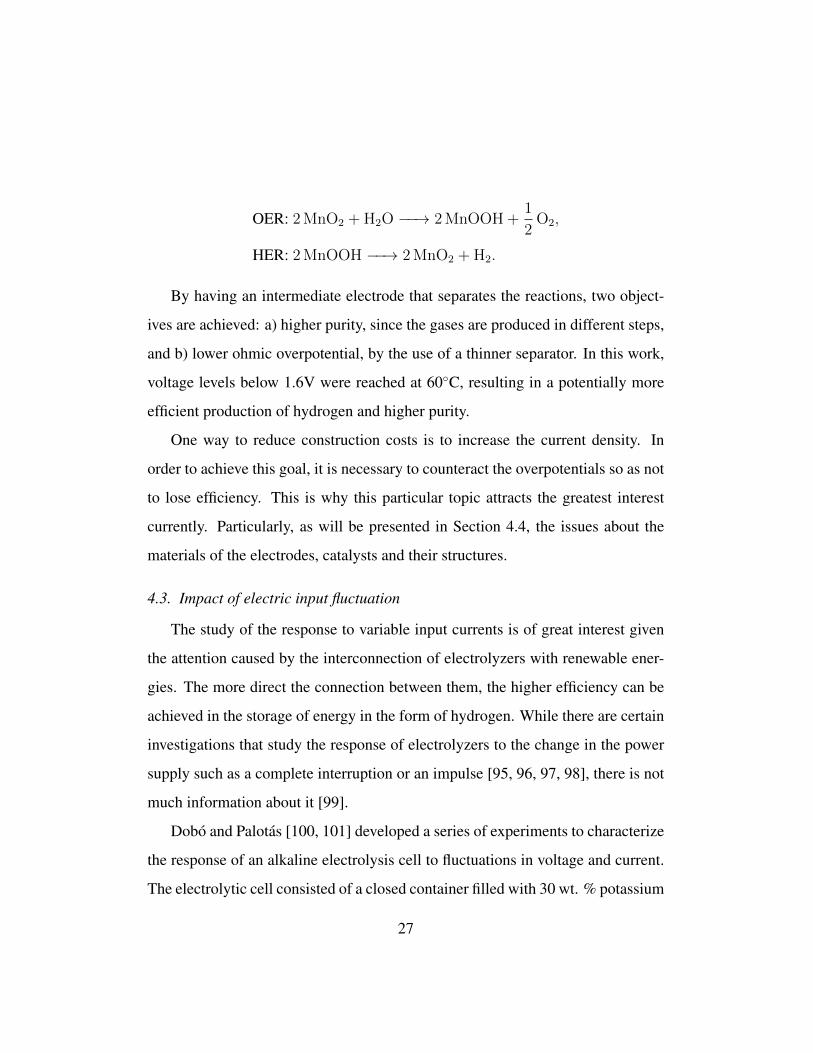
OER: 2 MnO2 + H2O −−→ 2 MnOOH +1
2O2,
HER: 2 MnOOH −−→ 2 MnO2 + H2.
By having an intermediate electrode that separates the reactions, two object-
ives are achieved: a) higher purity, since the gases are produced in different steps,
and b) lower ohmic overpotential, by the use of a thinner separator. In this work,
voltage levels below 1.6V were reached at 60◦C, resulting in a potentially more
efficient production of hydrogen and higher purity.
One way to reduce construction costs is to increase the current density. In
order to achieve this goal, it is necessary to counteract the overpotentials so as not
to lose efficiency. This is why this particular topic attracts the greatest interest
currently. Particularly, as will be presented in Section 4.4, the issues about the
materials of the electrodes, catalysts and their structures.
4.3. Impact of electric input fluctuation
The study of the response to variable input currents is of great interest given
the attention caused by the interconnection of electrolyzers with renewable ener-
gies. The more direct the connection between them, the higher efficiency can be
achieved in the storage of energy in the form of hydrogen. While there are certain
investigations that study the response of electrolyzers to the change in the power
supply such as a complete interruption or an impulse [95, 96, 97, 98], there is not
much information about it [99].
Dobo and Palotas [100, 101] developed a series of experiments to characterize
the response of an alkaline electrolysis cell to fluctuations in voltage and current.
The electrolytic cell consisted of a closed container filled with 30 wt. % potassium
27

hydroxide solution with flat plate stainless steel electrodes. In the former case,
the cell was fed with a sinusoidal voltage signal with amplitude a and frequency
f mounted on a direct voltage UDC . With an amplitude between 0 and 2V, a
frequency between 1Hz and 5000Hz and a direct voltage between 1.4V and 2.8V,
6512 experiments lasting 15s were carried out. In each case, the electric power
delivered and the gases produced were calculated, the second ones as a function of
the pressure change in the cell. The results obtained show that at greater amplitude
a and frequency f , the efficiency of the cell decreases. In turn, UDC values are
found in which the efficiency is maximum (around 2.2V). Efficiency is defined as
η = 100Q
[VmP
U0F
(1
zH2
+1
zO2
)]−1
,
where Q is the measured flow of gases produced, Vm is the molar volume of the
ideal gases for normal conditions, U0 is the theoretical decomposition voltage of
water, F is the Faraday constant and z is the charge number. A degradation of
efficiency is obtained with respect to that corresponding to the DC operation of up
to 20%. However, there are work zones in which the efficiency drops due to the
fluctuation in the input (<2%) can be considered negligible. It is concluded that it
is possible to accept fluctuation in the tension but it is recommended to soften the
ripple to obtain better results.
In the second case, the cell was fed with several current waveforms (sine, tri-
angle, sawtooth and square) characterized by the direct current IDC , the root mean
square (rms) value Irms and the frequency f . In turn, a ripple factor r is defined
as the relationship between the rms value of the Irms alternating component and
the continuous IDC value, thus comparing the different waveforms.
For frequencies between 1Hz and 10kHz, direct current between 1 kA m−2
and 5 kA m−2 and for amplitudes of the alternating component between 0 A m−2
28
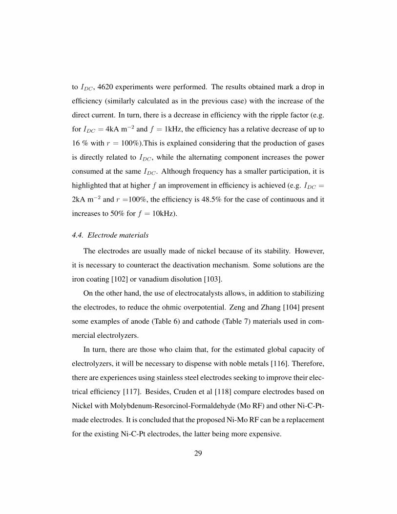
to IDC , 4620 experiments were performed. The results obtained mark a drop in
efficiency (similarly calculated as in the previous case) with the increase of the
direct current. In turn, there is a decrease in efficiency with the ripple factor (e.g.
for IDC = 4kA m−2 and f = 1kHz, the efficiency has a relative decrease of up to
16 % with r = 100%).This is explained considering that the production of gases
is directly related to IDC , while the alternating component increases the power
consumed at the same IDC . Although frequency has a smaller participation, it is
highlighted that at higher f an improvement in efficiency is achieved (e.g. IDC =
2kA m−2 and r =100%, the efficiency is 48.5% for the case of continuous and it
increases to 50% for f = 10kHz).
4.4. Electrode materials
The electrodes are usually made of nickel because of its stability. However,
it is necessary to counteract the deactivation mechanism. Some solutions are the
iron coating [102] or vanadium disolution [103].
On the other hand, the use of electrocatalysts allows, in addition to stabilizing
the electrodes, to reduce the ohmic overpotential. Zeng and Zhang [104] present
some examples of anode (Table 6) and cathode (Table 7) materials used in com-
mercial electrolyzers.
In turn, there are those who claim that, for the estimated global capacity of
electrolyzers, it will be necessary to dispense with noble metals [116]. Therefore,
there are experiences using stainless steel electrodes seeking to improve their elec-
trical efficiency [117]. Besides, Cruden et al [118] compare electrodes based on
Nickel with Molybdenum-Resorcinol-Formaldehyde (Mo RF) and other Ni-C-Pt-
made electrodes. It is concluded that the proposed Ni-Mo RF can be a replacement
for the existing Ni-C-Pt electrodes, the latter being more expensive.
29

Table 6: Oxygen overpotential of different electrode materials [taken from [104]]
Composition formula Method T (oC) Electrolyte C(mol dm−3) j (Am−2) ηoxygen (mV) Ref.
Ni+Spinel type Co3O4 Thermo-decomposition 25 KOH 1 1000 235± 7 [105]
Ni+La doped Co3O4 Thermo-decomposition 25 KOH 1 1000 224± 8 [105]
MnOx modified Au Electro-deposition 25 KOH 0.5 100 300 [106]
Li10% doped Co3O4 Spray pyrolysis RT KOH 1 10 550 [107]
Ni N/A 90 KOH 50 wt% 1000 300 [108]
La0.5Sr0.5CoO3 Spray-stiner 90 KOH 50 wt% 1000 250 [108]
Ni0.2Co0.8LaO3 Plasma jet projection 90 KOH 50 wt% 1000 270 [108]
Table 7: Hydrogen overpotential of different electrode materials [taken from [104]]
Composition formula Method T (oC) Electrolyte C(mol dm−3) j (Am−2) ηhydrogen (mV) Ref.
Ni-Fe-Mo-Zn Co-deposition 80 KOH 6 1350 83 [109]
Ni-S-Co Electro-deposition 80 NaOH 28 wt% 1500 70 [110]
Ni50%-Zn Electro-deposition N/A NaOH 6.25 1000 168 [111]
MnNi3.6Co0.75Mn0.4Al0.27 Arc melting 70 KOH 30 wt% 1000 39 [112]
Ti2Ni Arc melting 70 KOH 30 wt% 1000 16 [113]
Ni50%Al Melting 25 NaOH 1 1000 114 [114]
Ni75%Mo25% Co-deposition 80 KOH 6 3000 185 [115]
Ni80%Fe18% Co-deposition 80 KOH 6 3000 270 [115]
Ni73%W25% Co-deposition 80 KOH 6 3000 280 [115]
Ni60%Zn40% Co-deposition 80 KOH 6 3000 225 [115]
Ni90%Cr10% Co-deposition 80 KOH 6 3000 445 [115]
30

Table 8: Main electrocatalyst materials and their current development [taken from [119]]
Material Activity Stability Status
Raney Ni Sufficient activity Deactivation after intermittent opera-
tion
Commercially used
NiCo, NiFe High activity, which can be further im-
proved upon alloying with rare earths
Better stability than Raney Ni, but still
not optimal
Laboratory applications
NiFe2O4 Very high activity Long term stability Applied in lab-scale electrolysis with
polymeric membrane
NiMo Very high activity Long term stability Pyrophoric material: inappropriate for
commercialization
(Ni,Co)W High activity Unknown Laboratory applications
Co2Si Very high activity Unknown Laboratory applications
Ni3N High activity Unknown Laboratory applications
As stated previously, the study of catalysts is receiving increasing interest. As
stated by Sapountzi et al [119], the worldwide development of hydrogen produc-
tion by electrolysis is limited by the search for stable, active and abundant elec-
trocatalysts that allow intermittent conditions. The authors present in Table 8 the
main electrocatalyst materials and their current development. Another issue that is
being investigated is the use of nanostructures to obtain higher efficiencies or de-
crease the amount of precious metals needed. Some examples are the deposition
of Pd and Ru [120], the incorporation of NiO into a Ni-P matrix [121], the use of
Ni nanoparticles on carbon nanotubes [122] and the development of RuO2-NiO
nanorod arrays on a Ni foam substrate [123]. Table 9 shows the latest develop-
ments in the use of nanostructures showing the variety of forms and materials.
This list is not exhaustive given the large dispersion.
4.5. Gas-purity dependence
Haug et al [131] developed a series of experiments to analyze the variation
of the volumetric concentration of H2 in O2 at the outflow of a zero-gap alkaline
31

Table 9: Comparison of works using nanostructures to obtain higher electrolysis efficciencies
Material Nanostructure HER/OER a Activity Stability Ref
CoP Nanosheet@microwire
array on Nickel foam
OER High activity (296mv
@100mA)
At least 65h [124]
NiWO4 Nanowire on Ti mesh Both Good activity (101mV for HER
and 322mV for OER @20mA)
— [125]
CoTe2 – MnTe2 Hybrid nanowire on Ti mesh OER Sufficient activity (310mV
@50mA)
At least 60h [126]
Fe – NiCr2O4/NF Fe doped nanoparticles film OER Good activity (228mV @20mA
and 318mV @500mA)
At least 60h [127]
CoP3 Nanowire array HER Sufficient activity (76mV
@10mA)
At least 60h [128]
CoP Nanosheet on carbon cloth Both High activity (52mV for HER
and 300mV for OER @10mA)
— [129]
PtCo – Co/TiM Ultrafine alloy decorated
nanowire
HER Superior to Pt-based elec-
trocatalysts (70mV @46.5mA)
At least 50h [130]
aTested in Hydrogen or Oxygen Evolution Reaction
electrolyzer. In this way, states of operation that define the following trends are
achieved:
• The reduction in the electrolyte recirculation flow rate allows less impurit-
ies.
• A rise in the electrolyte concentration decreases the hydrogen content in
oxygen.
• An increase in the temperature of the electrolyte implies less impurities.
It is necessary to clarify that these tendencies are delimited by other relations
of commitment, as ohmic overpotential or properties of materials.
Another idea investigated is to know the change of the impurities with three
configurations of the circuit. The first and traditional one is the mixing of the
32

electrolyte recirculation circuits to the cell and the interconnection of both gas
separators (mixed). The second one is the independence of recirculations and gas
separators, while the third one keeps the recirculation circuits separated but al-
lows the interconnection of the gas separators (partly separated). It is observed
that there is an improvement in the purity when passing to separate recircula-
tion circuits while it is not considerable when the gas separators are independent.
However, the separation of the recirculation circuits does not allow the equaliz-
ation of KOH concentrations necessary for the suitable performance of the cell.
That is why two solutions that improve the purity are proposed:
• Partly separated method at low current densities (when impurities are higher)
and change to mixed method when higher current densities are reached.
• Period cycling of the order of half an hour between the methods partly sep-
arated and mixed to achieve an improvement in the purity with respect to
the traditional method.
5. Discussions
As presented in the current review, there are interesting alternative methods
for the production of hydrogen with virtually zero emissions, among them high-
lighting the production from biomass and electrolysis. Its biggest disadvantage is
the economic cost superior to industrial processes such as the SMR in both con-
struction and operation. It can be seen that these three technologies will coexist in
the medium term, waiting for the proportion of SMR to gradually decrease, gener-
ating two important niches to be filled by the other two methods: mass production
of hydrogen for industry and mobility from biomass, and electrolysis as an energy
buffer for renewable sources.
33

Within the area of electrolysis, a comparative analysis of the various existing
technologies was carried out. Advantages and disadvantages of the two commer-
cially available methods have been pointed out, observing opinions of authors in
favor of one and against another indistinctly. It is our opinion that both techno-
logies have benefits that lead to their use in different situations: in the case of
alkaline electrolyzers, more developed and tested, they are usable as large install-
ations for the stabilization of electrical networks or directly connected to large
wind or solar farms. On the other hand, for PEM electrolyzers, with better dy-
namics and gas quality, it is expected that they can be used as an intermediate
energy buffer in industrial plants or at a residential level. In any case, the need
to continue research lines to increase their efficiency and reduce their costs is
highlighted. Among them is the study of materials for electrodes, electrocatalysts
and separators. The other two technologies in development, the SOE and AEM
electrolyzers, must overcome the durability barriers in order to compete with the
previous ones in the medium to long term.
6. Conclusions
The search for alternative methods of power generation and transport has de-
veloped the concept of hydrogen economy. While today hydrogen is obtained
mainly from hydrocarbons, new technologies to achieve lower GHG emissions are
being developed and consolidated. This paper summarizes the different methods
of hydrogen production with emphasis on the current status of alkaline electro-
lysis. Among hydrogen methods, electrolysis stands out for ease of connection to
renewable energies, obtainable purity and their existing but nascent commercial-
ization.
34

In this paper, current lines of research on alkaline electrolyzers are discussed
as it is the ecofriendly-technology with the highest maturity so far. Nevertheless,
it requires improvements to be competitive against the production of fossil hydro-
gen, which means lowering construction and operating costs. The former depends
mainly on the materials of the electrodes, so simple or coated non-precious metals
are proposed. The later are strongly linked to the efficiency of the system which
implies reducing ohmic overpotentials and gases cross-linking of gases. For this
purpose, there are several proposals that will need to be deeply discused and ana-
lysed to find the optimum point of operation of alkaline electrolyzers.
The public has to be aware of the importance of reducing the GHG emis-
sions. The hydrogen economy and renewable energies are, until today, the best
solution. The development of these technologies needs the coworking between
politics, business and science. The aim of this paper is to give a concise and pre-
cise idea of the latest progress around the world related to hydrogen economy and,
specially, electrolysis in order to encourage the development and investigation in
this important matter.
References
[1] International Energy Agency, 9, rue de la Federation, 75739 Paris Cedex
15, France, Key world energy statistics 2017 (2016).
[2] SBC Energy Institute, Electricity Storage FactBook, White paper,
http://energystorage.org/resources/sbc-energy-institute-electricity-storage-
factbook (2013).
[3] T. Mahlia, T. Saktisahdan, A. Jannifar, M. Hasan, H. Matseelar, A review of
35

available methods and development on energy storage: technology update,
Renewable and Sustainable Energy Reviews 33 (2014) 532–545.
[4] S. Sharma, S. K. Ghoshal, Hydrogen the future transportation fuel: From
production to applications, Renewable and Sustainable Energy Reviews 43
(2015) 1151–1158.
[5] R. Chaubey, S. Sahu, O. James, S. Maity, A review on development of in-
dustrial process and emerging techniques for production of hydrogen from
renewable and sustainable sources, Renewable and Sustainable Energy Re-
views 23 (2015) 443–462.
[6] M. A. Abdalla, S. Hossain, O. B. Nisfindya, A. A. T., M. Dawoodb, A. K.
Azada, Hydrogen production, storage, transportation and key challenges
with applications: A review, Energy Conversion and Management 165
(2018) 602–627.
[7] F. Zhang, P. Zhao, M. Niu, J. Maddy, The survey of key technologies in hy-
drogen energy storage, International Journal of Hydrogen Energy 41 (2016)
14535–14552.
[8] S. Dutta, A review on production, storage of hydrogen and its utilization
as an energy resource, Journal of Industrial and Engineering Chemistry 20
(2014) 1148–1156.
[9] K. Mazloomi, C. Gomes, Hydrogen as an energy carrier: Prospects and
challenges, Renewable and Sustainable Energy Reviews 16 (2012) 3024–
3033.
36

[10] FreedomCAR & Fuel partnership, Hydrogen production: Overview
of technology options, https://www1.eere.energy.gov/
hydrogenandfuelcells/pdfs/h2_tech_roadmap.pdf
(2009).
[11] S. Schiebahn, T. Grube, M. Robinius, V. Tietze, B. Kumar, D. Stolten,
Power to gas: Technological overview, systems analysis and economic as-
sessment for a case study in Germany, International Journal of Hydrogen
Energy 40 (2015) 4285–4294.
[12] G. Gahleitner, Hydrogen from renewable electricity: An international re-
view of power-to-gas pilot plants for stationary applications, International
Journal of Hydrogen Energy 38 (2013) 2039–2061.
[13] M. Ball, M. Weeda, The hydrogen economy - vision or reality?, Interna-
tional Journal of Hydrogen Energy 40 (2015) 7903–7919.
[14] U. Albrecht, M. Altmann, J. Michalski, T. Raksha, W. Weindorf, Analyse
der Kosten Erneuerbarer Gase, Ponte Press, Ottobrunn, Germany, 2013.
[15] Nationale Organisation Wasserstoff, Berlin, Germany, Integration von
Wind-Wasserstoff-Systemen in das Energiesystem (2014).
[16] HyUnder, Assessment of the potential, the actors and relevant business
cases for large scale and long term storage of renewable electricity by H2
underground storage in Europe - executive summary (2014).
[17] M. L. Arlt, G. F. Cardoso, D. Weng, Hydrogen storage applications in in-
dustrial microgrids, in: 2017 IEEE Green Energy and Smart Systems Con-
ference (IGESSC), 2017, pp. 1–6. doi:10.1109/IGESC.2017.8283465.
37

[18] A. Ganeshan, D. G. Holmes, L. Meegahapola, B. P. McGrath, Enhanced
control of a hydrogen energy storage system in a microgrid, in: 2017 Aus-
tralasian Universities Power Engineering Conference (AUPEC), 2017, pp.
1–6. doi:10.1109/AUPEC.2017.8282434.
[19] F. Mueller-Langer, E. Tzimas, M. Kaltschmitt, S. Peteves, Techno-
economic assessment of hydrogen production processes for the hydrogen
economy for the short and medium term, International Journal of Hydrogen
Energy 32 (2007) 3797–3810.
[20] P. Nikolaidis, A. Poullikkas, A comparative overview of hydrogen produc-
tion processes, Renewable and Sustainable Energy Reviews 67 (2017) 597–
611.
[21] A. Ursua, Hydrogen production from water electrolysis: Current status and
future trends, Proceedings of the IEEE 100 (2012) 410–426.
[22] O. Schmidt, A. Gambhir, I. Staffell, A. Hawkes, J. Nelson, S. Few, Future
cost and performance of water electrolysis: An expert elicitation study,
International Journal of Hydrogen Energy 42 (2017) 30470–30492.
[23] D.-Y. Lee, A. Elgowainy, Q. Dai, Life cycle greenhouse gas emissions of
hydrogen fuel production from chlor-alkali processes in the United States,
Applied Energy 217 (2018) 467–479.
[24] S. K. Ngoh, D. Njomo, An overview of hydrogen gas production from solar
energy, Renewable and Sustainable Energy Reviews 16 (2012) 6782–6792.
[25] J. Holladay, J. Hu, D. King, Y. Wang, An overview of hydrogen production
technologies, Catalysis Today 139 (2009) 244–260.
38
[26] K. McHugh, Hydrogen production methods, MPR Associates Inc. (2005)
41.
[27] T. Paulmier, L. Fulcheri, Use of non-thermal plasma for hydrocarbon re-
forming, Chemical Engineering Journal 106 (2005) 59–71.
[28] B. Rozmiarek, Hydrogen generation from biomass-derived carbohydrates
via aqueous phase reforming process, Tech. rep., U.S. Department of En-
ergy, Washington DC (2008).
[29] Fuel cells and infrastructure technologies program, multi-year research, de-
velopment and demonstration plan, Tech. rep., U.S. Department of Energy
(2007).
[30] B. Sørensen, Hydrogen and Fuel Cells Emerging Technologies and Applic-
ations, Elsevier Academic Press, 2005.
[31] N. A. of Science, The Hydrogen Economy: Opportunities, Costs, Barriers,
and R&D needs, Natl. Academies Press, Washington DC, 2004.
[32] T. Laurinavichene, S. Kosourov, M. Ghirardi, M. Seibert, A. Tsy-
gankov, Prolongation of H2 photoproduction by immovilized, sulfur-
limited chlamydomonas reinhardtii cultures, Journal of Biotechnology
(2008) 275–277.
[33] K. Kovacs, G. Maroti, G. Rakhely, A novel approach for biohydrogen pro-
duction, International Journal of Hydrogen Energy 31 (2006) 1460–1468.
[34] D. Call, B. Logan, Hydrogen production in a single chamber microbial
39

electrolysis cell lacking a membrane, Environmental Science and Techno-
logy 42 (2008) 3401–3406.
[35] J. Turner, G. Sverdrup, M. Mann, P.-C. Maness, B. Kroposki, M. Ghirardi,
R. Evans, D. Blake, Renewable hydrogen production, International Journal
of Hydrogen Energy 32 (2008) 379–407.
[36] M.-R. de Valladares, Global trends and outlook for hydrogen, International
Energy Agency, December 2017.
[37] J. Turner, T. Deutsch, J. Head, P. Vallett, Photoelectrochemical wa-
ter systems for H2 production, in: DOE Hydrogen Program An-
nual Merit Review, U.S. Department of Energy, Washington DC,
http://www.hydrogen.energy.gov/pdfs/review07/pd_
10_turner.pdf (2007).
[38] P. Parthasarathy, S. Narayanan, Hydrogen production from steam gasific-
ation of biomass: Influence of process parameters on hydrogen yield - a
review, Renewable Energy 66 (2014) 570–579.
[39] S. E. Hosseini, M. A. Wahid, Hydrogen production from renewable and
sustainable energy resources: Promising green energy carrier for clean de-
velopment, Renewable and Sustainable Energy Reviews 57 (2016) 850–
866.
[40] J. Levene, M. Mann, R. Margolis, A. Milbrandt, An analysis of hydrogen
production from renewable electricity sources, Solar energy 84 (2007) 773–
780.
40

[41] H2A: Hydrogen Analysis Production Case Studies, Current Central Hy-
drogen Production from Natural Gas without CO2 Sequestration version
3.2018, https://www.nrel.gov/hydrogen/h2a-production-case-studies.html
(2018).
[42] R. Bhandari, C. Trundewind, P. Zapp, Life cycle assessment of hydrogen
production via electrolysis - a review, Journal of Cleaner Production 85
(2014) 151–163.
[43] I. Dincer, C. Acar, Review and evaluation of hydrogen production meth-
ods for better sustainability, International Journal of Hydrogen Energy 40
(2014) 11094–11111.
[44] Y. Zhang, I. Angelidaki, Microbial electrolysis cells turning to be versatile
technology: Recent advances and future challenges, Water Research 56
(2014) 11–25.
[45] M. Carmo, D. L. Fritz, J. Mergel, D. Stolten, A comprehensive review
on PEM water electrolysis, International Journal of Hydrogen Energy 38
(2013) 4901–4934.
[46] S. P. Badwal, S. Giddey, C. Munnings, Hydrogen production via solid elec-
trolytic routes, Wiley Interdisciplinary Reviews: Energy and Environment
2 (2013) 473–487.
[47] M. Laguna-Bercero, Recent advances in high temperature electrolysis us-
ing solid oxide fuel cells: A review, Journal of Power Sources 203 (2012)
4–16.
41

[48] L. Xiao, S. Zhang, J. Pan, C. Yang, M. He, L. Zhuang, J. Lu, First imple-
mentation of alkaline polymer electrolyte water electrolysis working only
with pure water, Energy & Environmental Science 5 (2012) 7869–7871.
[49] I. Vincent, D. Bessarabov, Low cost hydrogen production by anion ex-
change membrane electrolysis: A review, Renewable and Sustainable En-
ergy Reviews 81 (2018) 1690–1704.
[50] L. An, T. S. Zhao, Z. H. Chai, P. Tan, L. Zeng, Mathematical modeling of
an anion-exchange membrane water electrolyzer for hydrogen production,
International Journal of Hydrogen Energy 39 (2014) 19869–19876.
[51] C. C. Pavel, F. Cecconi, C. Emiliani, S. Santiccioli, A. Scaffidi, S. Catan-
orchi, M. Comotti, Highly efficient platinum group metal free based
membrane-electrode assembly for anion exchange membrane water elec-
trolysis, Angewandte Chemie International Edition 53 (2014) 1378–1381.
[52] X. Tang, L. Xiao, C. Yang, J. Lu, L. Zhuang, Noble fabrication of Ni-Mo
cathode for alkaline water electrolysis and alkaline polymer electrolyte wa-
ter electrolysis, International Journal of Hydrogen Energy 39 (2014) 3055–
3060.
[53] Y. Leng, G. Chen, A. J. Mendoza, T. B. Tighe, M. A. Hickner, C.-Y. Wang,
Solid-state water electrolysis with an alkaline membrane, Journal of the
American Chemical Society 134 (2012) 9054–9057.
[54] M. Faraj, M. Boccia, H. Miller, F. Martini, S. Borsacchi, M. Geppi,
A. Pucci, New LDPE based anion-exchange membranes for alkaline solid
42

polymeric electrolyte water electrolysis, International Journal of Hydrogen
Energy 37 (2012) 14992–15002.
[55] H. Ito, N. Kawaguchi, S. Someya, T. Munakata, Pressurized operation
of anion exchange membrane water electrolysis, Electrochimica Acta 297
(2019) 188–196.
[56] J. Parrondo, C. G. Arges, M. Niedzwiecki, E. B. Anderson, K. E. Ayersb,
V. Ramani, Degradation of anion exchange membranes used for hydrogen
production by ultrapure water electrolysis, Royal Society of Chemistry Ad-
vances 4 (2014) 9875–9879.
[57] J. R. Varcoe, R. C. T. Slade, Prospects for alkaline anionexchange mem-
branes in low temperature fuel cells, Fuel Cells 5 (2005) 187–200.
[58] B. Bauer, F. Effenberger, H. Strathmann, Anion-exchange with improved
alkaline stability, Desalination 79 (1990) 125–144.
[59] A. Buttler, H. Spliethoff, Current status of water electrolysis for energy
storage, grid balancing and sector coupling via power-to-gas and power-to-
liquids: A review, Renewable and Sustainable Energy Reviews 82 (2018)
2440–2454.
[60] K. A. Lewinski, D. van der Vliet, S. M. Luopa, NSTF advances for PEM
electrolysis - the effect of alloying on activity of NSTF electrolyzer cata-
lysts and performance of NSTF based PEM electrolyzers, ECS Transac-
tions 69 (2015) 893–917.
43

[61] S. Grigoriev, V. Porembskiy, S. Korobtsev, V. Fateev, F. Aupretre, P. Mil-
let, High-pressure PEM water electrolysis and corresponding safety issues,
International Journal of Hydrogen Energy 36 (2011) 2721–2728.
[62] A. S. Gago, J. Burkle, P. Lettenmeier, T. Morawietz, M. Handl, R. Hies-
gen, F. Burggraf, P. A. V. Beltran, K. A. Friedrich, Degradation of Proton
Exchange Membrane (PEM) electrolysis: The influence of current density,
ECS Transactions 86 (2018) 695–700.
[63] A. S. Gago, P. Lettenmeier, S. Stiber, A. S. Ansar, L. Wang, K. A. Friedrich,
Cost-effective PEM electrolysis: The quest to achieve superior efficiencies
with reduced investment, ECS Transactions 85 (2018) 3–13.
[64] S. Y. Gomez, D. Hotza, Current developments in reversible solid oxide fuel
cells, Renewable and Sustainable Energy Reviews 61 (2016) 155–174.
[65] S. P. Badwal, S. Giddey, C. Munnings, Emerging technologies, markets and
commercialization of solid-electrolytic hydrogen production, Wiley Inter-
disciplinary Reviews: Energy and Environment 7 (2018) 286–304.
[66] M. Felgenhauer, T. Hamacher, State-of-the-art of commercial electrolyzers
and on-site hydrogen generation for logistic vehicles in South Carolina,
International Journal of Hydrogen Energy 40 (2015) 2084–2090.
[67] M. Schalenbach, A. R. Zeradjanin, O. Kasian, S. Cherevko, K. J.
Mayrhofer, A perspective on low-temperature water electrolysis challenges
in alkaline and acidic technology, International Journal of Electrochemical
Science 13 (2018) 1173–1226.
44

[68] J. Divisek, P. Malinowski, J. Mergel, H. Schmitz, Improved construction of
an electrolytic cell for advanced alkaline water electrolysis, International
Journal of Hydrogen Energy 10 (1985) 383–388.
[69] M. Schalenbach, W. Lueke, D. Stolten, Hydrogen diffusivity and electro-
lyte permeability of the Zirfon PERL separator for alkaline water electro-
lysis, Journal of Electrochemical Society 163 (2016) 1480–1488.
[70] A. Li, Y. Sun, T. Yao, H. Han, Earth-abundant transition-metal-based elec-
trocatalysts for water electrolysis to produce renewable hydrogen, Chem-
istry European Journal 24 (2018) 18334–18355.
[71] J. Tian, Q. Liu, A. M. Asiri, X. Sun, Self-supported nanoporous cobalt
phosphide nanowire arrays: An efficient 3D hydrogen-evolving cathode
over the wide range of pH 014, Journal of the American Chemical Society
136 (2014) 7857–7950.
[72] S. Meyer, A. V. Nikiforov, I. M. Petrushina, K. Kohler, E. Christensen, J. O.
Jensen, N. J. Bjerrum, Transition metal carbides (WC, Mo2C, TaC, NbC)
as potential electrocatalysts for the hydrogen evolution reaction (HER) at
medium temperatures, International Journal of Hydrogen Energy 40 (2015)
2905–2911.
[73] Q. Feng, G. Liu, B. Wei, Z. Zhang, H. Li, H. Wang, A review of proton ex-
change membrane water electrolysis on degradation mechanisms and mit-
igation strategies, Journal of Power Sources 366 (2017) 33–55.
[74] S. Sun, Z. Shao, H. Yu, G. Li, B. Yi, Investigations on degradation of the
45
long-term proton exchange membrane water electrolysis stack, Journal of
Power Sources 267 (2014) 515–520.
[75] A. Kusoglu, A. M. Karlsson, M. H. Santare, S. Cleghorn, W. B. Johnson,
Mechanical behavior of fuel cell membranes under humidity cycles and ef-
fect of swelling anisotropy on the fatigue stresses, Journal of Power Sources
170 (2007) 345–358.
[76] M. Chandesris, V. Medeau, N. Guillet, S. Chelghoum, D. Thoby, F. Fouda-
Onana, Membrane degradation in PEM water electrolyzer: Numerical
modeling and experimental evidence of the influence of temperature and
current density, International Journal of Hydrogen Energy 40 (2015) 1353–
1366.
[77] C. Rakousky, U. Reimer, K. Wippermann, M. Carmo, W. Lueke, D. Stolten,
An analysis of degradation phenomena in polymer electrolyte membrane
water electrolysis, Journal of Power Sources 326 (2016) 120–128.
[78] H. Vandenborre, R. Leysen, L. H. Baetsle, Alkaline inorganic-membrane-
electrolyte (IME) water electrolysis, International Journal of Hydrogen En-
ergy 5 (1980) 165–171.
[79] P. Vermeiren, W. Adriansens, J. P. Moreels, R. Leysen, Evaluation of the
Zirfon separator for use in alkaline water electrolysis and Ni-H2 batteries,
International Journal of Hydrogen Energy 23 (1998) 321–324.
[80] K. Rajeshwar, R. McConnell, S. Licht, Solar Hydrogen Generation. Toward
a renewable energy future, Springer-Verlag, 2008.
46

[81] T. Ogawa, M. Takeuchi, Y. Kajikawa, Analysis of trends and emer-
ging technologies in water electrolysis research based on a computational
method: A comparison with fuel cell research, Sustainability 10 (2018)
478–501.
[82] K. Onda, T. Kyakuno, K. Hattori, K. Ito, Prediction of production power
for high-pressure hydrogen by high-pressure water electrolysis, Journal of
Power Sources 132 (2004) 64–70.
[83] C. Ziems, D. Tannert, H. J. Krautz, Project presentation: design and install-
ation of advanced high pressure alkaline electrolyzer-prototypes, Energy
Procedia 29 (2012) 744–753.
[84] A. Roy, S. Watson, D. Infield, Comparison of electrical energy efficiency of
atmospheric and high-pressure electrolysers, International Journal of Hy-
drogen Energy 31 (2006) 1964–1979.
[85] F. Allebrod, C. Chatzichristodoulou, M. B. Mogensen, Alkaline electrolysis
cell at high temperature and pressure of 250oC and 42bar, Journal of Power
Sources 229 (2013) 22–31.
[86] J. Ganley, High temperature and pressure alkaline electrolysis, Interna-
tional Journal of Hydrogen Energy 34 (2009) 3604–3611.
[87] O. Ulleberg, Modeling of advanced alkaline electrolyzers: a system simula-
tion approach, International Journal of Hydrogen Energy 28 (2003) 21–33.
[88] H. Barthels, W. Brocke, K. Bonhoff, H. Groehn, G. Heuts, M. Lennartz,
H. Mai, J. Mergel, L. Schmid, P. Ritzenhoff, Phoebus-Julich: an autonom-
47

ous energy supply system comprising photovoltaics, electrolytic hydrogen,
fuel cell, International Journal of Hydrogen Energy 23 (1998) 295–301.
[89] A. Ursua, P. Sanchis, Static-dynamic modelling of the electrical behaviour
of a commercial advanced alkaline water electrolyser, International Journal
of Hydrogen Energy 37 (2012) 18598–18614.
[90] A. Roy, Dynamic and transient modelling of electrolysers powered by re-
newable energy sources and cost analysis of electrolytic hydrogen, Ph.D.
thesis, Loughborough University (2006).
[91] K. Zouhri, S. Lee, Evaluation and optimization of the alkaline water elec-
trolysis ohmic polarization: Exergy study, International Journal of Hydro-
gen Energy 41 (2016) 7253–7263.
[92] B. Choi, D. Panthi, M. Nakoji, T. Kabutomori, K. Tsutsumi, A. Tsutsumi, A
novel water-splitting electrochemical cycle for hydrogen production using
an intermediate electrode, Chemical Engineering Science 157 (2017) 200–
208.
[93] P. Charvin, S. Abanades, G. Flamant, F. Lemort, Two-step water splitting
thermochemical cycle based on iron oxide redox pair for solar hydrogen
production, Energy 32 (2007) 1124–1133.
[94] A. Steinfeld, Solar hydrogen production via a two-step water splitting ther-
mochemical cycle based on zn/zno redox reactions, International Journal
of Hydrogen Energy 27 (2005) 611–619.
48

[95] K. Mazloomi, N. Sulaiman, S. A. Ahmad, N. Yunus, Analysis of the fre-
quency response of a water electrolysis cell, International Journal of Elec-
trochemical Science 8 (2013) 3731–3739.
[96] N. Shimizu, S. Hotta, T. Sekiya, O. Oda, A novel method of hydrogen
generation by water electrolysis using an ultra-short-pulse power supply,
Journal of applied electrochemistry 36 (2006) 419–423.
[97] M. Vanags, J. Kleperis, G. Bajars, Water electrolysis with inductive voltage
pulses, in: Electrolysis, InTech, 2012.
[98] A. H. Shaaban, Pulsed DC and anode depolarization in water electrolysis
for hydrogen generation, Tech. rep., Air Force Civil Engineering Support
Agency (1994).
[99] S. Mazloomi, N. Sulaiman, Influencing factors of water electrolysis elec-
trical efficiency, Renewable and Sustainable Energy Reviews 16 (2012)
4257–4263.
[100] Z. Dobo, A. B. Palotas, Impact of the voltage fluctuation of the power sup-
ply on the efficiency of alkaline water electrolysis, International Journal of
Hydrogen Energy 41 (2016) 11849–11856.
[101] Z. Dobo, A. B. Palotas, Impact of the current fluctuation on the efficiency
of alkaline water electrolysis, International Journal of Hydrogen Energy 42
(2017) 5649–5656.
[102] A. Mauer, D. Kirk, T. Steven, The role of iron in the prevention of
nickel electrode deactivation in alkaline electrolysis, Electrochimica Acta
52 (2007) 3505–3509.
49

[103] R. M. Abouatallah, D. W. Kirk, S. J. Thorpe, J. W. Graydon, Reactivation of
nickel cathodes by dissolved vanadium species during hydrogen evolution
in alkaline media, Electrochimica Acta 47 (2001) 613–621.
[104] K. Zeng, D. Zhang, Recent progress in alkaline water electrolysis for hy-
drogen production and applications, Progress in Energy and Combustion
Science 36 (2010) 307–326.
[105] R. Singh, D. Mishra, Anindita, A. Sinha, A. Singh, Novel electrocatalysts
for generating oxygen from alkaline water electrolysis, Electrochemistry
Communications 9 (2007) 1369–1373.
[106] M. El-Deab, M. Awad, A. Mohammad, T. Ohsaka, Enhanced water elec-
trolysis: electrocatalytic generation of oxygen gas at manganese oxide
nanorods modified electrodes, Electrochemistry Communications 9 (2007)
2082–2087.
[107] M. Hamdani, M. Pereira, J. Douch, A. Addi, Y. Berghoute, M. Mendonca,
Physicochemical and electrocatalytic properties of LiCo3O4 anodes pre-
pared by chemical spray pyrolysis for application in alkaline water electro-
lysis, Electrochimica Acta 49 (2004) 1555–1563.
[108] H. Wendt, H. Hofmann, V. Plzak, Materials research and development of
electrocatalysts for alkaline water electrolysis, Materials Chemistry and
Physics 22 (1989) 27–49.
[109] F. Crnkovic, S. Machado, L. Avaca, Electrochemical and morphological
studies of electrodeposited NiFeMoZn alloys tailored for water electrolysis,
International Journal of Hydrogen Energy 29 (2004) 249–254.
50

[110] Q. Han, K. Liu, J. Chen, X. Wei, Hydrogen evolution reaction on amorph-
ous NiSCo alloy in alkaline medium, International Journal of Hydrogen
Energy 28 (2003) 1345–1352.
[111] G. Sheela, M. Pushpavanam, S. Pushpavanam, Hydrogen evolution reac-
tion on amorphous NiSCo alloy in alkaline medium, International Journal
of Hydrogen Energy 27 (2002) 627–633.
[112] W. Hu, Electrocatalytic properties of new electrocatalysts for hydrogen
evolution in alkaline water electrolysis, International Journal of Hydrogen
Energy 25 (2000) 111–118.
[113] W. Hu, J. Lee, Electrocatalytic properties of Ti2Ni/NiMo composite elec-
trodes for hydrogen evolution reaction, International Journal of Hydrogen
Energy 23 (1998) 253–257.
[114] P. Los, A. Rami, A. Lasia, Hydrogen evolution reaction on NiAl electrodes,
Journal of Applied Electrochemistry 23 (1993) 135–140.
[115] I. Raj, Nickel-based, binary-composite electrocatalysts for the cathodes in
the energy-efficient industrial-production of hydrogen from alkaline-water
electrolytic cells, Journal of Materials Science 28 (1993) 4375–4382.
[116] D. Abbott, Keeping the energy debate clean: How do we supply the world’s
energy needs?, Proceedings of the IEEE 98 (2009) 42–66.
[117] M. J. Lavorante, J. I. Franco, Performance of stainless steel 316L electrodes
with modified surface to be use in alkaline water electrolyzers, International
Journal of Hydrogen Energy 41 (2016) 9731–9737.
51
[118] A. Cruden, D. Infield, M. Kiaee, T. G. Douglas, A. Roy, Development of
new materials for alkaline electrolysers and investigation of the potential
electrolysis impact on the electrical grid, Renewable Energy 49 (2013) 53–
57.
[119] F. M. Sapountzi, J. M. Gracia, C. K.-J. Weststrate, H. O. Fredriksson, J. H.
Niemantsverdriet, Electrocatalysts for the generation of hydrogen, oxygen
and synthesis gas, Progress in Energy and Combustion Science 58 (2017)
1–35.
[120] B. Pierozynski, T. Mikolajczyk, K. IM., Hydrogen evolution at catalytically
modified nickel foam in alkaline solution, Journal of Power Sources 271
(2014) 231–238.
[121] S. Shibli, G. Harikrishnan, V. Anupama, K. Chinchu, M. BN, Development
of nano NiO incorporated nickel-phosphorus coatings for electrocatalytic
applications, Surface and Coatings Technology 262 (2015) 48–55.
[122] M. A. McArthur, S. Jorge, L. Coulombe, S. Omanovic, Synthesis and char-
acterization of 3D Ni nanoparticle/carbon nanotube cathodes for hydrogen
evolution in alkaline electrolyte, Journal of Power Sources 266 (2014) 365–
373.
[123] L. Zhang, K. Xiong, S. Chen, L. Li, Z. D. Deng, Zihua Wei, In situ growth
of ruthenium oxide-nickel oxide nanorod arrays on nickel foam as a binder-
free integrated cathode for hydrogen evolution, Journal of Power Sources
274 (2015) 114–120.
52

[124] X. Ji, R. Zhang, X. Shi, A. M. Asiri, B. Zheng, X. Sun, Fabrication of
hierarchical CoP nanosheet microwire array via space-confined phosphid-
ation toward high-efficiency water oxidation electrocatalysis under alkaline
conditions, Nanoscale 10 (2018) 7941–7945.
[125] Y. Ji, L. Yang, X. Ren, G. Cui, X. Xiong, X. Sun, Full water splitting
electrocatalyzed by NiWO4 nanowire array, ACS Publications 6 (2018)
9555–9559.
[126] Z. Wang, X. Ren, L. Wang, G. Cui, H. Wang, X. Sun, A hierarchical CoTe
2–MnTe 2 hybrid nanowire array enables high activity for oxygen evolution
reactions, Chemical Communications 54 (2018) 10993–10996.
[127] J. Zhao, X. Li, G. Cui, X. Sun, Highly-active oxygen evolution electrocata-
lyzed by an Fe-doped NiCr 2 o 4 nanoparticle film, Chemical Communica-
tions 54 (2018) 5462–5465.
[128] Y. Ji, L. Yang, X. Ren, G. Cui, X. Xiong, X. Sun, Nanoporous CoP3
nanowire array: acid etching preparation and application as a highly act-
ive electrocatalyst for the hydrogen evolution reaction in alkaline solution,
ACS Sustainable Chemistry & Engineering 6 (2018) 11186–11189.
[129] T. Liu, L. Xie, J. Yang, R. Kong, G. Du, A. M. Asiri, X. Sun, L. Chen, Self-
standing CoP nanosheets array: A three-dimensional bifunctional catalyst
electrode for overall water splitting in both neutral and alkaline media,
ChemElectroChem 4 (2017) 1840–1845.
[130] Z. Wang, X. Ren, Y. Luo, L. Wang, G. Cui, F. Xie, H. Wang, Y. Xie, X. Sun,
Ultrafine platinum–cobalt alloy decorated cobalt nanowire array with su-
53

perb activity toward alkaline hydrogen evolution, Nanoscale 10 (2018)
12302–12307.
[131] P. Haug, M. Koj, T. Turek, Influence of process conditions on gas purity
in alkaline water electrolysis, International Journal of Hydrogen Energy
42 (15) (2017) 9406–9418.
54