Advances and Breakthroughs in Diffusers for ... - kdm.p.lodz.pl · Mechanics and Mechanical...
14
Mechanics and Mechanical Engineering Vol. 22, No. 2 (2018) 495–508 c ⃝ Lodz University of Technology Advances and Breakthroughs in Diffusers for Compressors and Pumps: A Short History of Diffusers for Centrifugal Machines David Japikse Concepts NREC, LLC White River Junction, VT, USA [email protected] Received (23 June 2018) Revised (24 July 2018) Accepted (27 August 2018) The diffuser plays an indispensable role in setting the useable flow range and efficiency for centrifugal machinery. Key aspects of the history and design of such diffusers are overviewed followed by a look at current, novel ideas for better systems. Improved machinery can be expected in the coming years due to decades of development work in this field. Keywords : diffusers, flow range, efficiency, centrifugal compressors, centrifugal pumps. 1. Role of diffuser in centrifugal stages In centrifugal stages, at least eight (8) basic functions can be involved in the per- formance of a diffuser; sometimes, certain ones are chosen as design targets for optimization; in other instances, all functions may be involved. The eight are: 1. Kinetic energy recovery (except high-flow choke conditions) always losing total pressure, 2. Flow regulation (good impeller may operate at low flow by matching to a low- flow diffuser), 3. A potentially significant structural element, 4. A possible flow match to next element (set the velocity triangles), 5. Strong possible interaction (coupling) with the impeller flow field, 6. Tendency to ”clean up” the flow field (steadier and more uniform),
Transcript of Advances and Breakthroughs in Diffusers for ... - kdm.p.lodz.pl · Mechanics and Mechanical...

Mechanics and Mechanical Engineering
Vol. 22, No. 2 (2018) 495–508c⃝ Lodz University of Technology
Advances and Breakthroughs in Diffusers for Compressors and Pumps:A Short History of Diffusers for Centrifugal Machines
David Japikse
Concepts NREC, LLCWhite River Junction, VT, USA
Received (23 June 2018)
Revised (24 July 2018)
Accepted (27 August 2018)
The diffuser plays an indispensable role in setting the useable flow range and efficiencyfor centrifugal machinery. Key aspects of the history and design of such diffusers areoverviewed followed by a look at current, novel ideas for better systems. Improvedmachinery can be expected in the coming years due to decades of development work inthis field.
Keywords: diffusers, flow range, efficiency, centrifugal compressors, centrifugal pumps.
1. Role of diffuser in centrifugal stages
In centrifugal stages, at least eight (8) basic functions can be involved in the per-formance of a diffuser; sometimes, certain ones are chosen as design targets foroptimization; in other instances, all functions may be involved. The eight are:
1. Kinetic energy recovery (except high-flow choke conditions) always losing totalpressure,
2. Flow regulation (good impeller may operate at low flow by matching to a low-flow diffuser),
3. A potentially significant structural element,
4. A possible flow match to next element (set the velocity triangles),
5. Strong possible interaction (coupling) with the impeller flow field,
6. Tendency to ”clean up” the flow field (steadier and more uniform),

496 Japikse, D.
7. Reduction of radial side loads, and
8. Potential reduction of noise and vibration (or make it worse).
Just how these attributes are utilized will have enormous impact on the finalstage design and its performance. They are often the key to stability, and surely tostage efficiency. These points, and many more, are background for this review andare detailed in Japikse, 1984 [1] and 1996 [2].
2. History of diffuser research
The fluid device, called a diffuser, has been around since Roman times. Rouse andInce [3], page 28, state: “Each consumer. . . did not pay for the amount of water heactually used, but a flat rate for the lease of a certain discharge. The standardizedsize of the distributing pipe leading from the receptacle was originally taken asthe discharge measure. However, it was soon found by dishonest consumers. . . thatthe lead pipes [the standardized discharge element per the lease] could be easilypounded out to yield a greater cross section.” By Bernoulli’s principle, one cansee how the pressure rise along the device must increase while always matching thedownstream exit pressure, which would be the atmospheric pressure. Hence, thepressure at the inlet to the device would drop, and a greater pressure differencealong the pipe system would exist, giving a higher flow rate.
The first research into the performance of diffusers, evidently, did not occuruntil about 1910 in a study by Gibson [4], and while this may be the first studyto examine the actual fluid dynamics of diffusers, it barely scratched the surfaceof a deep understanding of diffuser performance. The first mapping of a familyof diffusers was achieved by Reid [5] at Stanford University in 1953, as shown inFigure 1.
Figure 1 The first construction of today’s common diffuser performance map
Advances and Breakthroughs in Diffusers for Compressors ... 497
Reid’s map presents the performance (Cp = static pressure rise/inlet dynamic head)of a set of different diffusers constructed at various lengths (L) for given inlet width(W) and an overall exit over inlet area ratio. In subsequent plots, other authorshave used the symbols S or N for L, but the definitions are the same, and L is nowthe common symbol.
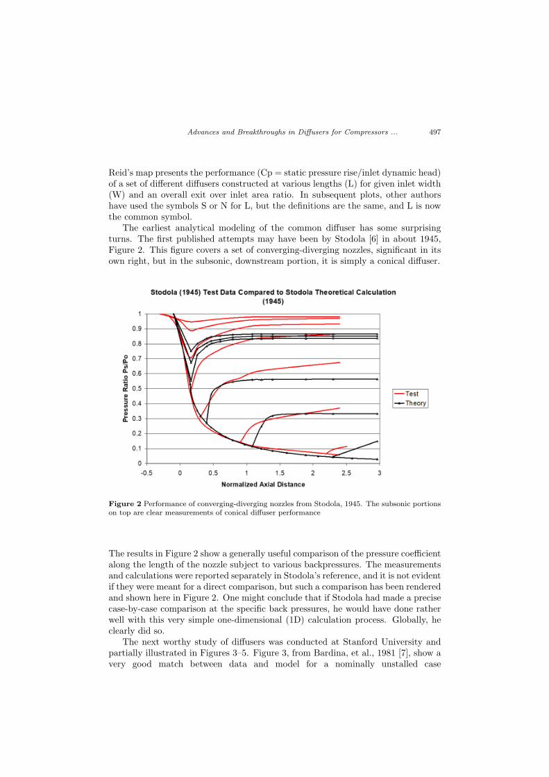
The earliest analytical modeling of the common diffuser has some surprisingturns. The first published attempts may have been by Stodola [6] in about 1945,Figure 2. This figure covers a set of converging-diverging nozzles, significant in itsown right, but in the subsonic, downstream portion, it is simply a conical diffuser.
Figure 2 Performance of converging-diverging nozzles from Stodola, 1945. The subsonic portionson top are clear measurements of conical diffuser performance
The results in Figure 2 show a generally useful comparison of the pressure coefficientalong the length of the nozzle subject to various backpressures. The measurementsand calculations were reported separately in Stodola’s reference, and it is not evidentif they were meant for a direct comparison, but such a comparison has been renderedand shown here in Figure 2. One might conclude that if Stodola had made a precisecase-by-case comparison at the specific back pressures, he would have done ratherwell with this very simple one-dimensional (1D) calculation process. Globally, heclearly did so.
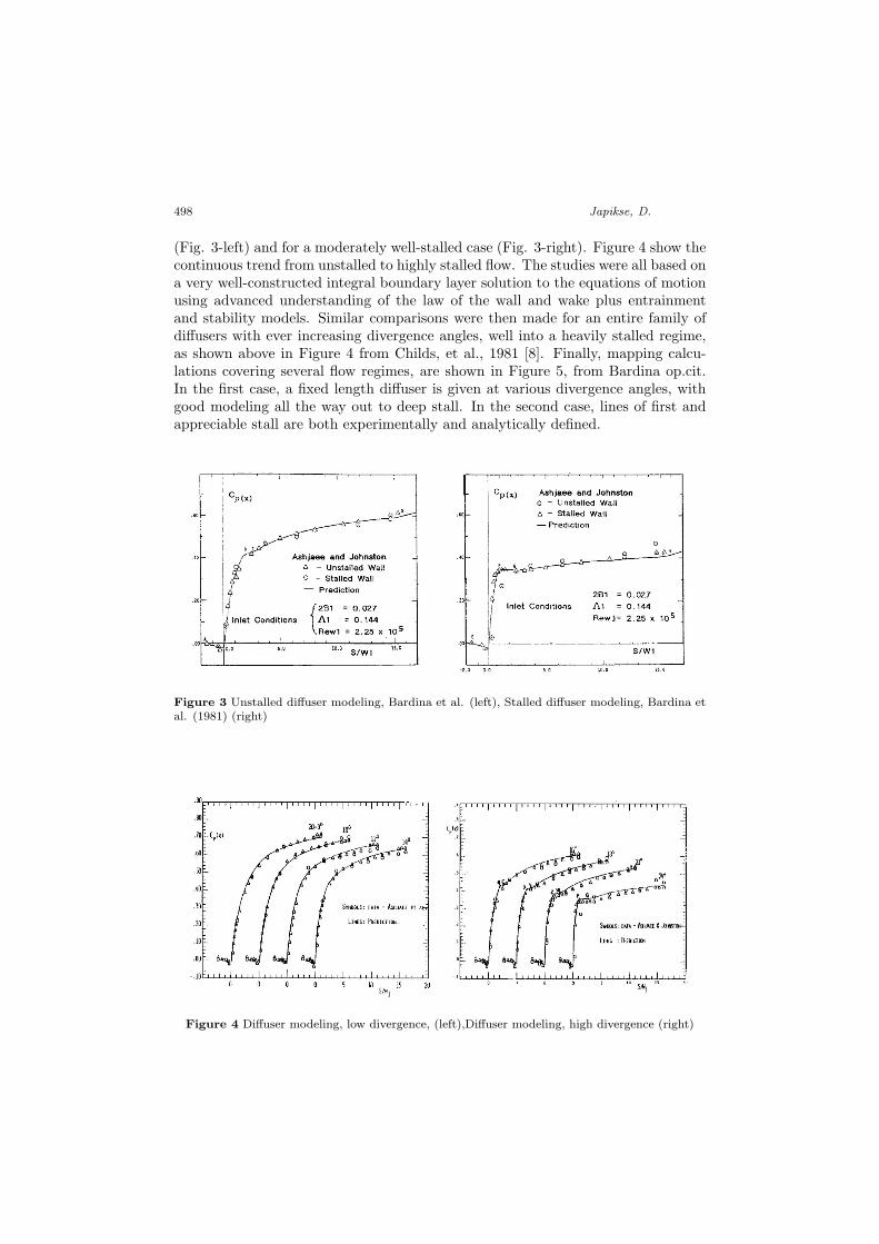
The next worthy study of diffusers was conducted at Stanford University andpartially illustrated in Figures 3–5. Figure 3, from Bardina, et al., 1981 [7], show avery good match between data and model for a nominally unstalled case
498 Japikse, D.
(Fig. 3-left) and for a moderately well-stalled case (Fig. 3-right). Figure 4 show thecontinuous trend from unstalled to highly stalled flow. The studies were all based ona very well-constructed integral boundary layer solution to the equations of motionusing advanced understanding of the law of the wall and wake plus entrainmentand stability models. Similar comparisons were then made for an entire family ofdiffusers with ever increasing divergence angles, well into a heavily stalled regime,as shown above in Figure 4 from Childs, et al., 1981 [8]. Finally, mapping calcu-lations covering several flow regimes, are shown in Figure 5, from Bardina op.cit.In the first case, a fixed length diffuser is given at various divergence angles, withgood modeling all the way out to deep stall. In the second case, lines of first andappreciable stall are both experimentally and analytically defined.
Figure 3 Unstalled diffuser modeling, Bardina et al. (left), Stalled diffuser modeling, Bardina etal. (1981) (right)
Figure 4 Diffuser modeling, low divergence, (left),Diffuser modeling, high divergence (right)

Advances and Breakthroughs in Diffusers for Compressors ... 499
Figure 5 Modeling through multiple flow regimes (left), Modeling stall levels (right)
The next step in modeling is clearly for CFD, which is commonly applied toa full machine problem, in this case the diffusers for radial flow compressors andpumps. Unfortunately, while it should be quite practical with today’s tools and avery diligent investigator, we seem to be lacking any study that has significantlysurpassed the much simpler boundary layer analysis given above when it comes tomodeling a full diffuser map! Nonetheless, recent studies in the laboratory and withCFD have shown great promise for stage design even if not for the simpler diffusersgiven above (which elements are used in complete stage layouts). Ohta et al. (2010)[9] have carefully studied the role of the diffuser leading edge vortex; Robinson etal. (2012) [10] have closely examined the impeller-diffuser interaction with powerfulunsteady CFD calculations and rendered some convincing evidence of the voracityof time accurate modeling; Borm and Kau (2012) [11] tested several CFD codes andturbulence models against impeller-diffuser test data and gave insights to applica-tion, while Everitt et al. (2016) [12] gave a broad study of impeller outlet conditionsand their view of how these conditions impact the diffuser performance.
3. Classes of diffusers
Diffusers of many types have been used in a great variety of pump and compressorstages. Table 1, below, is a matrix summary of the studies conducted within theConcepts NREC (CN) High-Performance Diffuser Consortium. There are sevengeneric types of diffusers, with many variations possible.
Some of these could be combined into a common genre, but the nearly indepen-dent treatment given to each in the technical literature conspires for this listing.Variations around these types are noted by degree of passage pinch (width reduc-tion), use of flow control grooves, and so forth.

500 Japikse, D.
Table 1 A ranking of diffuser types and levels of research conducted at CN through consortium
programs
Impeller Type Di�
user Class Tes�
ng and Type (y = yes; n = no; p = planned; n/a = not applic.) Gr'ved Covers
Vls-f Vls-r Vls-lt Vls-b Vls-pa Ch-t Ch-a Ch-d Con LSA HSA Tnd Flat Vls Vaned
Ns1 = 110, pr = 3.5 y y n y n y n y n y n y y y y
Ns2 = 110, pr = 3.5 n n n n n n n y n y n n y n p
Ns3 = 110, pr = 3.5 n n n n n n n p n p n n p n p
Ns = 85, pr = 4.5 y n n n n y n n y/n y n n/a n n n
Ns = 55, pr = 1.8 y n y n n n/a n/a n/a n/a y n/a n/a n n n
Vls-f = Vaneless-front pinch Ch-t = Channel-tangen�
al divergence LSA = Low Solidity Airfoil
Vls-r = Vaneless-rear pinch Ch-a = Channel-axial divergence HSA = High Solidity Airfoil
Vls-lt = Vaneless-linear taper Ch-d = Channel-double divergence Tnd = Tandem Airfoils
Vls-b = Vaneless-both sides pinched Areas of special interest Flat = Flat Plate LSA Equivalent
Vls-pa = Vaneless-partial height vanesCon = Circular X-sec�
on Ns1: r2=1.35" Im-1; Ns2: r2=1.35" Im-2; Ns3: r2=2.70" Im-3
The seven generic types are:
1. Vaneless (VLS, the most common of all, by far)
2. The low solidity airfoil (LSA)
3. The high solidity airfoil (HSA)
4. The channel diffuser (Ch)
5. The conical diffuser (Con)
6. The tandem diffuser (Tnd)
7. The flat-plate diffuser (Flat)
In developing a design, there are many common considerations, including spaceavailable, performance required, cost of product, operating range needed, and soforth. Specialized research has found that best performance requires care with theimpeller exit /diffuser inlet and may be the most important area for diffuser design,with all other design parameters coming second. There is a strong probability ofusing Flow-wise Grooved Covers1 as part of future designs, whether vaneless orvaned (patents involved). There is always a reasonable chance of a standardizeddesign working well; perhaps a flat-plate variant will meet many needs. It mustbe said, however, that much more work is needed to learn the complete physics ofimpeller exit distortion.
1Japikse, D., “Flow control structures for turbomachines and methods of designing the same”,United States Patent No. 9,970,456 B2, May 15, 2018.
Advances and Breakthroughs in Diffusers for Compressors ... 501
4. Reliability of design
There is no doubt that CFD will play the dominant role in understanding diffuserperformance in general, and specifically for centrifugal stage design. Accumula-tive work leads in one direction: one must be able to model unsteady, transitorybehavior with transitional shear layers, and diverse inlet distortions covering veloc-ity, pressure, and flow angle profiles, as well as turbulence and vorticity variations.Until recently, this was a very tall order to fill, virtually unobtainable as it wouldseem. However, today it is nearly all within one’s reach: commercial CFD offerscompetitive options to cover all the issues listed above, and the use of Cloud com-puting offers essentially unlimited computational resources that readily translateinto speed as well.
Figure 6 Range versus single-stage pressure ratio for centrifugal compressors. Diversity of diffusersis used across the range of compressor applications
However, the issue of turbulence modeling remains significant. Current modelstrace their roots back to studies of flat-plate shear layers with only mild adversepressure gradients, and many turbomachinery flow fields have strong swirl, strongadverse pressure gradients, and complex turbulence and vorticity. While this willtake quite a while to sort out, it is reassuring to note the early 1980s studies citedabove showing remarkable agreement just using boundary layer theory to achievebroad and useful agreement. We await further work and understanding in the nearfuture.
5. Overview of applications, current and future
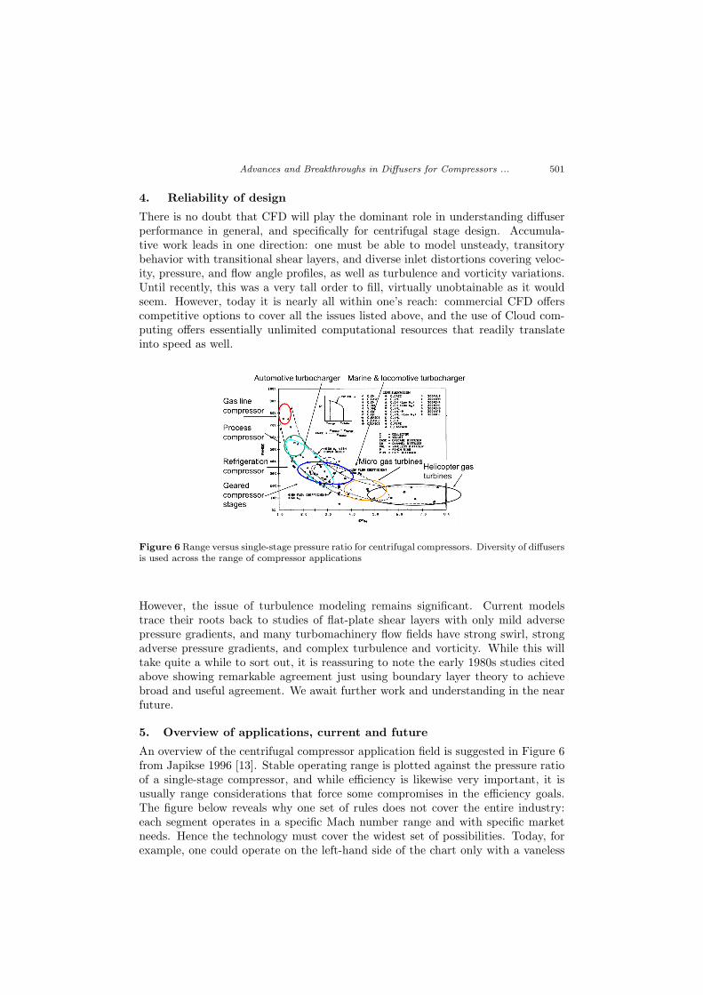
An overview of the centrifugal compressor application field is suggested in Figure 6from Japikse 1996 [13]. Stable operating range is plotted against the pressure ratioof a single-stage compressor, and while efficiency is likewise very important, it isusually range considerations that force some compromises in the efficiency goals.The figure below reveals why one set of rules does not cover the entire industry:each segment operates in a specific Mach number range and with specific marketneeds. Hence the technology must cover the widest set of possibilities. Today, forexample, one could operate on the left-hand side of the chart only with a vaneless

502 Japikse, D.
diffuser and on the right-hand side only with a channel or conical diffuser, andmarket needs would never be met if one tried to reverse these!
The details of diffuser design for all markets are vast and cannot be coveredhere, but a starting point can be found in Chapter 3 of the reference by Japikse(1996), ibid. To open the matter for discussion, the illustrations given below do notrepresent current design, but do point toward future advances that may change thefield considerably.
Figure 7 Comparison of modeling for a vaneless diffuser using a mixing plane method (Stanitzmodel) versus a coupled rotor-stator calculation using progressive mixing of the impeller exit flowentering the diffuser over considerable radial distance
5.1. Lessons from vaneless diffuser data matching
The ubiquitous vaneless diffuser can illustrate important issues. Figure 7 from Du-bitsky and Japikse (2008) [14] shows a detailed modeling study compared to detaileddata, including full flow field traverse data giving mass-averaged total pressure andyaw angle, as well as wall static pressures for a vaneless diffuser. The modeling isa time-cyclic model of the two-zone impeller model, but without sudden impellerexit mixing and rather progressive mixing into the vaneless diffuser. This modelingwas carried out using the one-dimensional differential equations, common to theart, for both radial momentum and tangential momentum and various mixing andmass transport relationships for the flow after it leaves the impeller. Hence, it isa two-dimensional model, with time variation, and with first-order viscous effects.Current mixing plane CFD calculations are inferior, as they suppress all the tan-gential variations into a mixed-out average state. Key observations can be made:two comparisons on total pressure are given, and one of them closely matches themeasured values, while the other fails even the proper trend (while each is forcedto match the measured static pressures). The correct trend could only be achievedby suppressing sudden expansion mixing and using the progressive mixing with theradius. This agreement is also true for the flow angles given in the figures. Thisstudy fundamentally shows that a mixing plane solution for CFD modeling of animpeller and diffuser is highly suspect at best!

Advances and Breakthroughs in Diffusers for Compressors ... 503
5.2. Grooved covers
The most complex part of the impeller exit / diffuser inlet flow problem is causedby the impact of the secondary flow leaving the impeller and entering the diffuserwith a highly distorted set of velocity/pressure profiles. The so-called secondaryflow leaving the impeller is weak in radial momentum, and hence, is tangential indirection when leaving the impeller, in the absolute frame of reference. Nonethe-less, this flow element has considerable velocity and total pressure that currentlyis largely wasted. One test of this issue is to use flow-wise cover grooves near theimpeller exit to re-guide some of this flow in a better direction (this technology isthoroughly patented in many countries). Figure 8 shows an example.
Figure 8 Illustration of a grooved cover
Figure 9 Characteristic improvements in stability using flow-wise cover grooves
Measured results for the grooved cover are given below, in Figure 9, for one in-stance, with many more already reported. The remarkable improvement in rangeis noteworthy.
5.3. Interdigitated vanes
Figure 10 shows the use of partial height vanes on one surface and another set onthe opposite surface, with or without the possible use of a few full height vanes. The

504 Japikse, D.
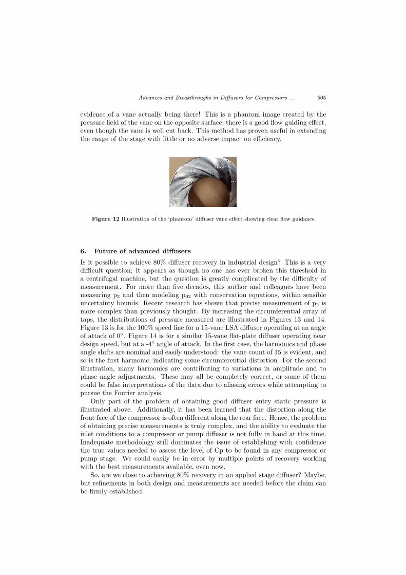
case in point here uses a set of partial height vanes on the shroud side and a differentset of partial height vanes on the opposite surface forming an interdigitated set ofopposing and offset partial height vane groupings. The results were excellent forrange extension on both sides of the map, with little or no compromise in efficiency.Indeed, the new map, in Figure 11 is broader and is an easier map to work within design. Best methods for design optimization are being worked out at this time.The final illustration, Figure 12 is a flow visualization picture showing the ‘phantomeffect’ of the missing vane sections.
Figure 10 Interdigitated partial height vane, notional diagram
1.00
1.20
1.40
1.60
1.80
2.00
2.20
2.40
2.60
2.80
3.00
3.20
3.40
3.60
3.80
4.00
0.10 0.20 0.30 0.40 0.50 0.60
PR
ts (
Pco
ll/P
00
)
Mref
2017 - Build 31 60mm Super Di�
user #4
2017-Build31-Super Di�
user #4 Imp#1
2017-Build28-Super Di�
user #1 Imp#1
80K
100K120K
135K
+45%
+27%
+48%
+41%
Figure 11 Performance of the interdigitated vane set
This is a picture of an interdigitated LSDA diffuser set. Where the word ‘vane’appears in the picture, a partial height vane is actually present and can be seen.Where the words ‘no vane’ appear, there is no vane close to the surface, and thepartial height vane is opposed and attached to the other surface with a considerablegap with respect to the illustrated surface. Nonetheless, there does appear to be
Advances and Breakthroughs in Diffusers for Compressors ... 505
evidence of a vane actually being there! This is a phantom image created by thepressure field of the vane on the opposite surface; there is a good flow-guiding effect,even though the vane is well cut back. This method has proven useful in extendingthe range of the stage with little or no adverse impact on efficiency.
Figure 12 Illustration of the ‘phantom’ diffuser vane effect showing clear flow guidance
6. Future of advanced diffusers
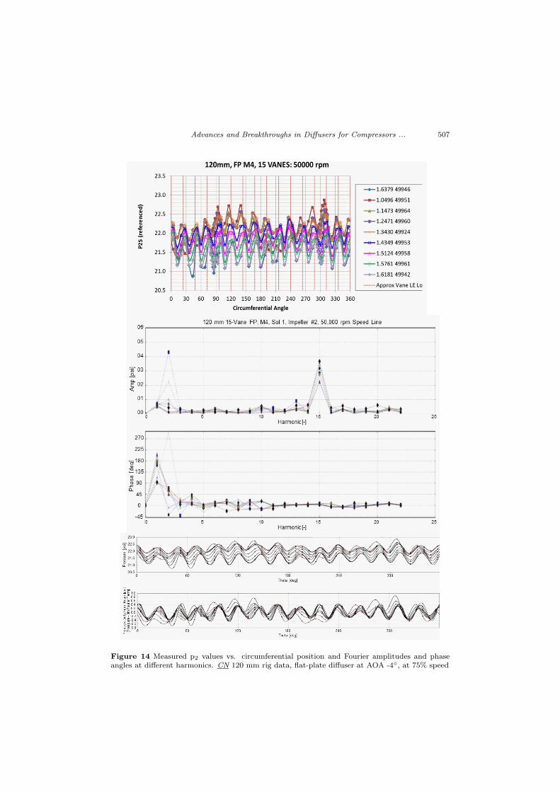
Is it possible to achieve 80% diffuser recovery in industrial design? This is a verydifficult question; it appears as though no one has ever broken this threshold ina centrifugal machine, but the question is greatly complicated by the difficulty ofmeasurement. For more than five decades, this author and colleagues have beenmeasuring p2 and then modeling p02 with conservation equations, within sensibleuncertainty bounds. Recent research has shown that precise measurement of p2 ismore complex than previously thought. By increasing the circumferential array oftaps, the distributions of pressure measured are illustrated in Figures 13 and 14.Figure 13 is for the 100% speed line for a 15-vane LSA diffuser operating at an angleof attack of 0◦. Figure 14 is for a similar 15-vane flat-plate diffuser operating neardesign speed, but at a -4◦ angle of attack. In the first case, the harmonics and phaseangle shifts are nominal and easily understood: the vane count of 15 is evident, andso is the first harmonic, indicating some circumferential distortion. For the secondillustration, many harmonics are contributing to variations in amplitude and tophase angle adjustments. These may all be completely correct, or some of themcould be false interpretations of the data due to aliasing errors while attempting topursue the Fourier analysis.
Only part of the problem of obtaining good diffuser entry static pressure isillustrated above. Additionally, it has been learned that the distortion along thefront face of the compressor is often different along the rear face. Hence, the problemof obtaining precise measurements is truly complex, and the ability to evaluate theinlet conditions to a compressor or pump diffuser is not fully in hand at this time.Inadequate methodology still dominates the issue of establishing with confidencethe true values needed to assess the level of Cp to be found in any compressor orpump stage. We could easily be in error by multiple points of recovery workingwith the best measurements available, even now.
So, are we close to achieving 80% recovery in an applied stage diffuser? Maybe,but refinements in both design and measurements are needed before the claim canbe firmly established.

506 Japikse, D.
Figure 13 Measured p2 values vs. circumferential position and Fourier amplitudes and phaseangles at different harmonics. CN 120 mm rig data, LSA diffuser at AOA 0◦, at 100% speed
Advances and Breakthroughs in Diffusers for Compressors ... 507
Figure 14 Measured p2 values vs. circumferential position and Fourier amplitudes and phaseangles at different harmonics. CN 120 mm rig data, flat-plate diffuser at AOA -4◦, at 75% speed
508 Japikse, D.
7. Conclusion
The diffuser is an important part of all centrifugal compressor stages and manypump stages. It has been employed for a very long time, but significant issues stillexist for its optimum application in truly advanced designs. This paper points toprogress and issues in this process.
8. Acknowledgements
All sponsors of the CN Diffuser Consortium investigation are heartily thanked fortheir sponsorship and critical engagement during the work that has led to the un-derstandings presented herein.
References
[1] Japikse, D.: A new diffuser mapping technique, J. Fluids Eng, 108, 2, 148–156,1984.
[2] Japikse, D.: Centrifugal Compressor Design and Performance, Concepts ETI, Inc.,Wilder, VT, USA, 1996.
[3] Rouse, H., and Ince, S.: History of Hydraulics, Springer-Verlag New York, Inc.,New York, NY, USA, 1959.
[4] Gibson, A.: On the flow of water through pipes and passages having converging ordiverging boundaries, Proc Royal Soc (London), 83, 563, A, 366–378, 1910.
[5] Reid, E. G.: Performance characteristics of plane-wall two-dimensional diffusers,NACA-TN-2888, 1953.
[6] Stodola, A., and Loewenstein, L. C.: Steam and Gas Turbines, 1, Peter Smith,New York, NY, USA, 1945.
[7] Bardina, J. G., et al.: A prediction method for planar diffuser flows, J. Fluids Eng,103, 3, 315–321, 1981.
[8] Childs, R. E., Ferziger, J. H., and Kline, S. J.: A computational method forsubsonic compressible flow in diffusers, Stanford University, Department of Mechani-cal Engineering, PD-24, 1981.
[9] Ohta, Y., Goto, T., and Outa, E.: Unsteady behavior and control of diffuserleading-edge vortex in a centrifugal compressor, Proceedings of ASME Turbo Expo2010, GT2010-22394, Glasgow, UK, 2010.
[10] Robinson, C., Casey, M., Hutchinson, B., and Steed R.: Impeller-diffuser in-teraction in centrifugal compressors, Proceedings of ASME Turbo Expo 2012, GT2012-69151, Copenhagen, DE, 2012.
[11] Borm, O., and Kau, H-P: Unsteady aerodynamics of a centrifugal compressorstage – validation of two different CFD solvers, Proceedings of ASME Turbo Expo2012, GT2012-69636, Copenhagen, DE, 2012.
[12] Everitt, J., Spakovszky, Z., Rusch, D., and Schiffmann, J.: The role of impelleroutflow conditions on the performance of vaned diffusers, Proceedings of ASME TurboExpo 2016, GT2016-56168, Seoul, South Korea, 2016.
[13] Japikse, D..: op. cit., 1996.
[14] Dubitsky, O. B., and Japikse, D.: Vaneless diffuser advanced model (2005D), J.Turbomach., 130, 1, 2008.