Advanced Virtual Private LAN Service - Cisco Virtual Private LAN Service ... VSS MEC is used for...
13
© 2013 Cisco and/or its affiliates. All rights reserved. This document is Cisco Public Information. Page 1 of 13 Deployment Guide Advanced Virtual Private LAN Service Introduction Globalization, business process optimization, and the need for continuous computing operations motivate businesses to seek solutions that can both distribute and unite data centers over geographically dispersed locations. Geographically distributed data centers are desired for mutual backup to reduce interruption from a local disaster and also to facilitate data center maintenance. Ideally, computing operations can switch transparently between sites, maintaining user sessions, application availability, and access to data resources. Virtual machine technology is increasingly used for distributed data center operations. Additionally, certain applications increasingly require the extension of VLANs and subnets across Layer 3 and Multiprotocol Label Switching (MPLS) networks between or within data centers and campus networks. In this challenging environment, a solution that enables fast, reliable, high-capacity, and highly scalable data center interconnection is essential. Such a solution is available with virtual private LAN service (VPLS), a technology that provides Ethernet connectivity over packet-switched WANs. VPLS supports the connection of multiple sites in a single bridged domain over a managed IP or IP and MPLS (IP/MPLS) network. VPLS presents an Ethernet interface, simplifying the LAN and WAN boundary for enterprise customers and helping enable rapid and flexible service provisioning. Data centers, each having their own Ethernet LAN, can be united in a virtual LAN (VLAN) over a WAN by using VPLS. Advanced VPLS The Cisco ® Layer 2 VPN (L2VPN) Advanced VPLS (A-VPLS) feature introduces the following enhancements to VPLS: ● Capability to load-balance traffic across multiple core interfaces using equal-cost multipathing (ECMP) ● Command-line interface (CLI) enhancements to facilitate configuration of the L2VPN A-VPLS feature ● Support for redundant Cisco Data Center Interconnect (DCI) and provider-edge switches (Figure 1)
Transcript of Advanced Virtual Private LAN Service - Cisco Virtual Private LAN Service ... VSS MEC is used for...
© 2013 Cisco and/or its affiliates. All rights reserved. This document is Cisco Public Information. Page 1 of 13
Deployment Guide
Advanced Virtual Private LAN Service
Introduction
Globalization, business process optimization, and the need for continuous computing operations motivate
businesses to seek solutions that can both distribute and unite data centers over geographically dispersed
locations. Geographically distributed data centers are desired for mutual backup to reduce interruption from a local
disaster and also to facilitate data center maintenance. Ideally, computing operations can switch transparently
between sites, maintaining user sessions, application availability, and access to data resources. Virtual machine
technology is increasingly used for distributed data center operations.
Additionally, certain applications increasingly require the extension of VLANs and subnets across Layer 3 and
Multiprotocol Label Switching (MPLS) networks between or within data centers and campus networks.
In this challenging environment, a solution that enables fast, reliable, high-capacity, and highly scalable data
center interconnection is essential. Such a solution is available with virtual private LAN service (VPLS), a
technology that provides Ethernet connectivity over packet-switched WANs. VPLS supports the connection of
multiple sites in a single bridged domain over a managed IP or IP and MPLS (IP/MPLS) network. VPLS presents
an Ethernet interface, simplifying the LAN and WAN boundary for enterprise customers and helping enable rapid
and flexible service provisioning. Data centers, each having their own Ethernet LAN, can be united in a virtual LAN
(VLAN) over a WAN by using VPLS.
Advanced VPLS
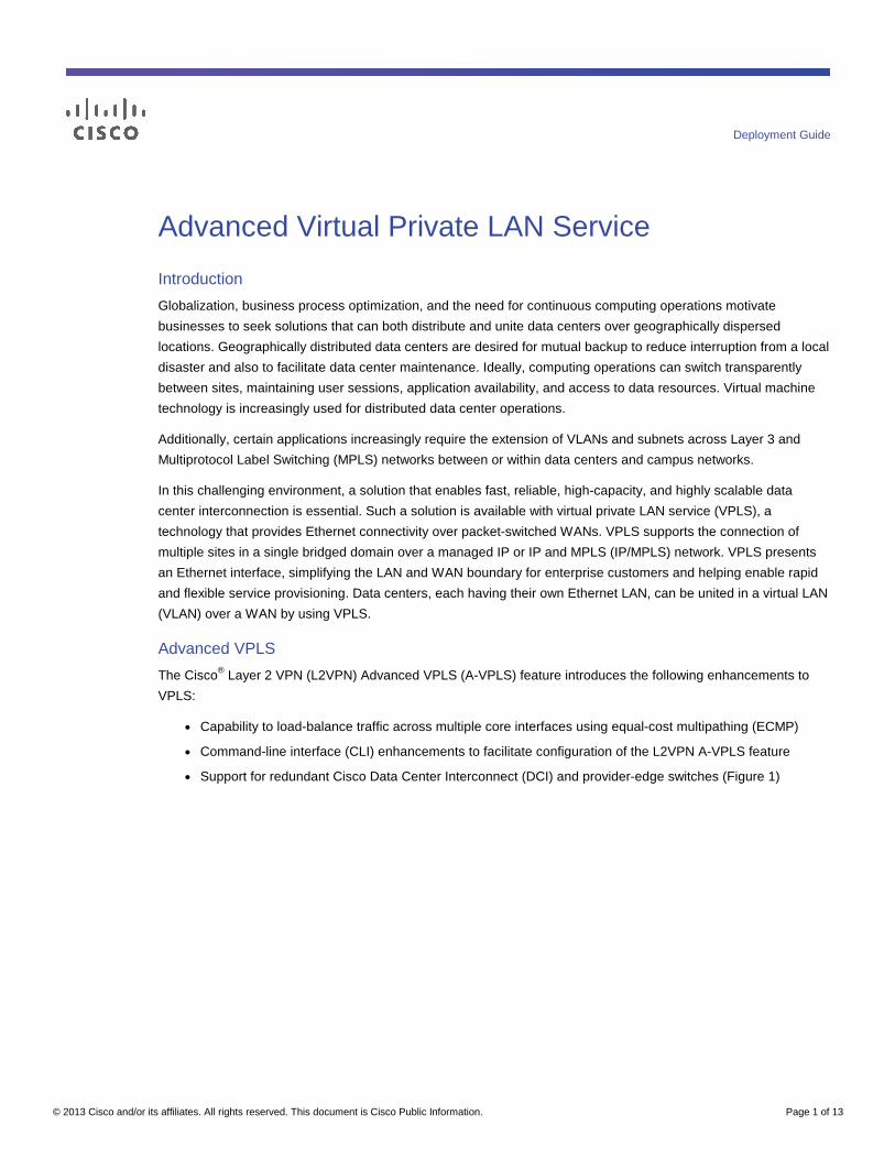
The Cisco® Layer 2 VPN (L2VPN) Advanced VPLS (A-VPLS) feature introduces the following enhancements to
VPLS:
● Capability to load-balance traffic across multiple core interfaces using equal-cost multipathing (ECMP)
● Command-line interface (CLI) enhancements to facilitate configuration of the L2VPN A-VPLS feature
● Support for redundant Cisco Data Center Interconnect (DCI) and provider-edge switches (Figure 1)
© 2013 Cisco and/or its affiliates. All rights reserved. This document is Cisco Public Information. Page 2 of 13
Figure 1. Cisco DCI and A-VPLS
Easy Configuration
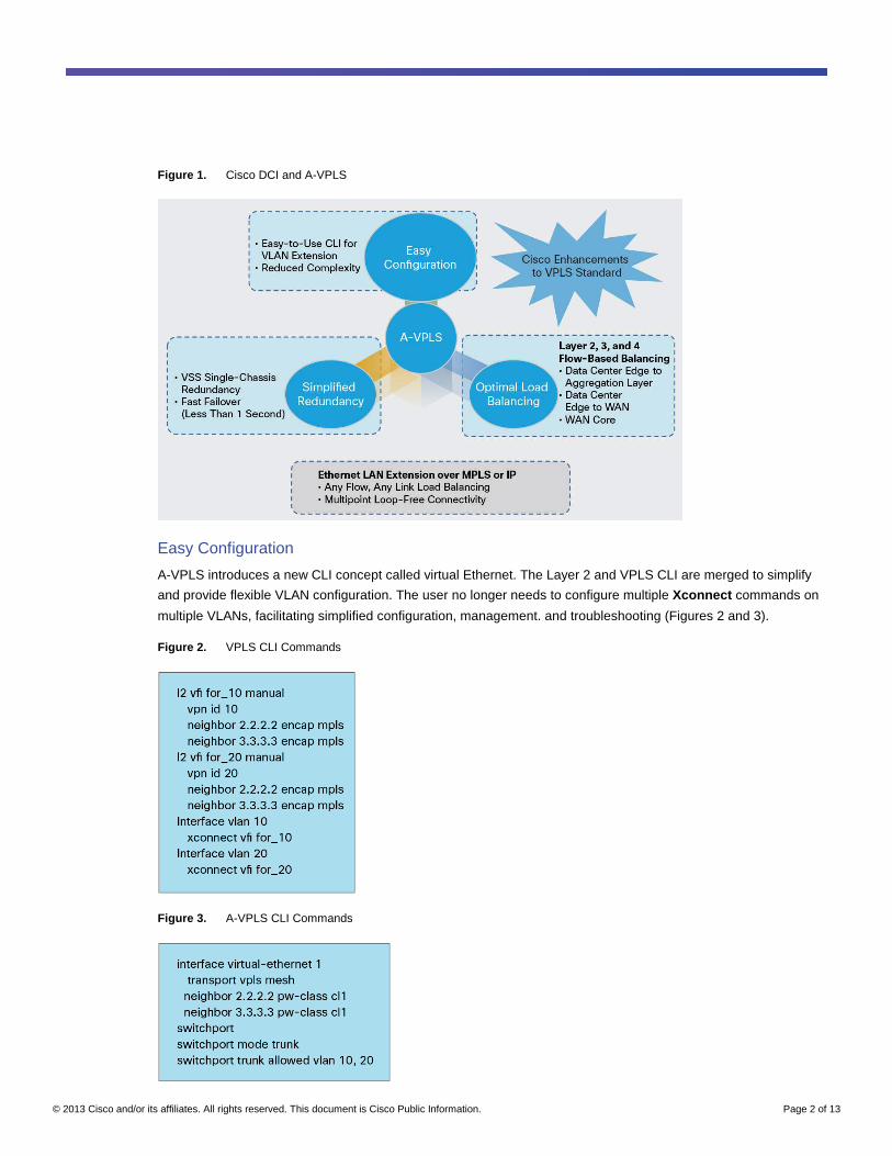
A-VPLS introduces a new CLI concept called virtual Ethernet. The Layer 2 and VPLS CLI are merged to simplify
and provide flexible VLAN configuration. The user no longer needs to configure multiple Xconnect commands on
multiple VLANs, facilitating simplified configuration, management. and troubleshooting (Figures 2 and 3).
Figure 2. VPLS CLI Commands
Figure 3. A-VPLS CLI Commands
© 2013 Cisco and/or its affiliates. All rights reserved. This document is Cisco Public Information. Page 3 of 13
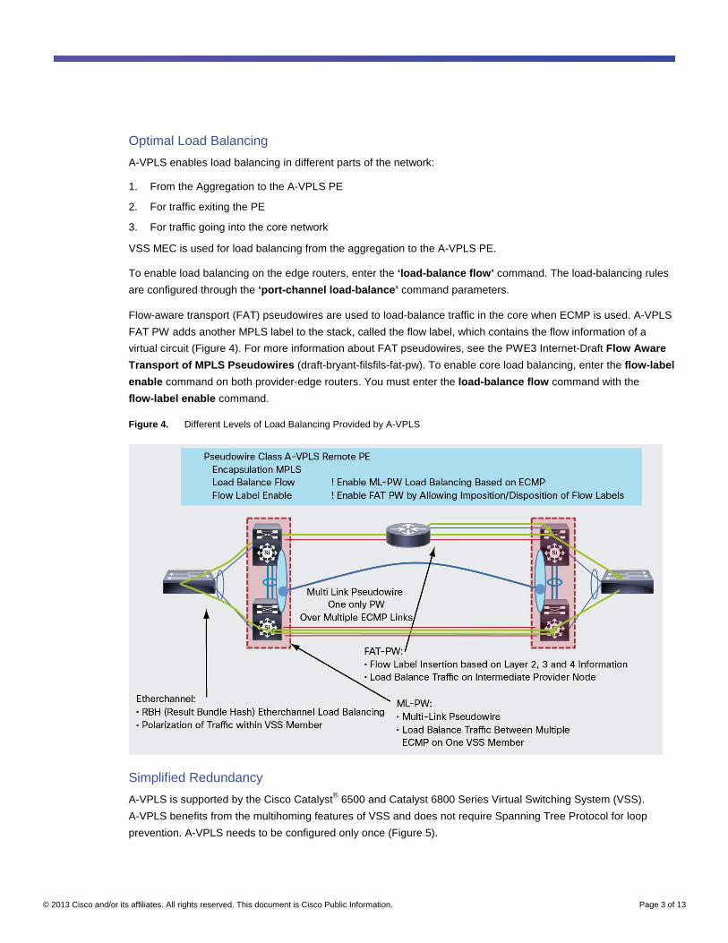
Optimal Load Balancing
A-VPLS enables load balancing in different parts of the network:
1. From the Aggregation to the A-VPLS PE
2. For traffic exiting the PE
3. For traffic going into the core network
VSS MEC is used for load balancing from the aggregation to the A-VPLS PE.
To enable load balancing on the edge routers, enter the ‘load-balance flow’ command. The load-balancing rules
are configured through the ‘port-channel load-balance’ command parameters.
Flow-aware transport (FAT) pseudowires are used to load-balance traffic in the core when ECMP is used. A-VPLS
FAT PW adds another MPLS label to the stack, called the flow label, which contains the flow information of a
virtual circuit (Figure 4). For more information about FAT pseudowires, see the PWE3 Internet-Draft Flow Aware
Transport of MPLS Pseudowires (draft-bryant-filsfils-fat-pw). To enable core load balancing, enter the flow-label
enable command on both provider-edge routers. You must enter the load-balance flow command with the
flow-label enable command.
Figure 4. Different Levels of Load Balancing Provided by A-VPLS
Simplified Redundancy
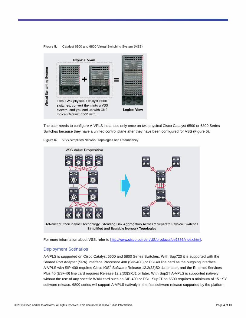
A-VPLS is supported by the Cisco Catalyst® 6500 and Catalyst 6800 Series Virtual Switching System (VSS).
A-VPLS benefits from the multihoming features of VSS and does not require Spanning Tree Protocol for loop
prevention. A-VPLS needs to be configured only once (Figure 5).
© 2013 Cisco and/or its affiliates. All rights reserved. This document is Cisco Public Information. Page 4 of 13
Figure 5. Catalyst 6500 and 6800 Virtual Switching System (VSS)
The user needs to configure A-VPLS instances only once on two physical Cisco Catalyst 6500 or 6800 Series
Switches because they have a unified control plane after they have been configured for VSS (Figure 6).
Figure 6. VSS Simplifies Network Topologies and Redundancy
For more information about VSS, refer to http://www.cisco.com/en/US/products/ps9336/index.html.
Deployment Scenarios
A-VPLS is supported on Cisco Catalyst 6500 and 6800 Series Switches. With Sup720 it is supported with the
Shared Port Adapter (SPA) Interface Processor 400 (SIP-400) or ES+40 line card as the outgoing interface.
A-VPLS with SIP-400 requires Cisco IOS® Software Release 12.2(33)SXI4a or later, and the Ethernet Services
Plus 40 (ES+40) line card requires Release 12.2(33)SXJ1 or later. With Sup2T A-VPLS is supported natively
without the use of any specific WAN card such as SIP-400 or ES+. Sup2T on 6500 requires a minimum of 15.1SY
software release. 6800 series will support A-VPLS natively in the first software release supported by the platform.
© 2013 Cisco and/or its affiliates. All rights reserved. This document is Cisco Public Information. Page 5 of 13
A-VPLS can be deployed in the following layers in the network:
● A-VPLS can be initiated from the core layer.
● Existing aggregation-layer switches can be used to extend the Layer 2 domain with A-VPLS and integrated
routing and bridging (IRB) for A-VPLS (refer to the IRB configuration for additional details about IRB).
● Existing aggregation-layer switches can be used to extend the Layer 2 domain with A-VPLS and IRB for
A-VPLS. A separate Cisco DCI and services Layer can be created to initiate A-VPLS to extend data center
domains.
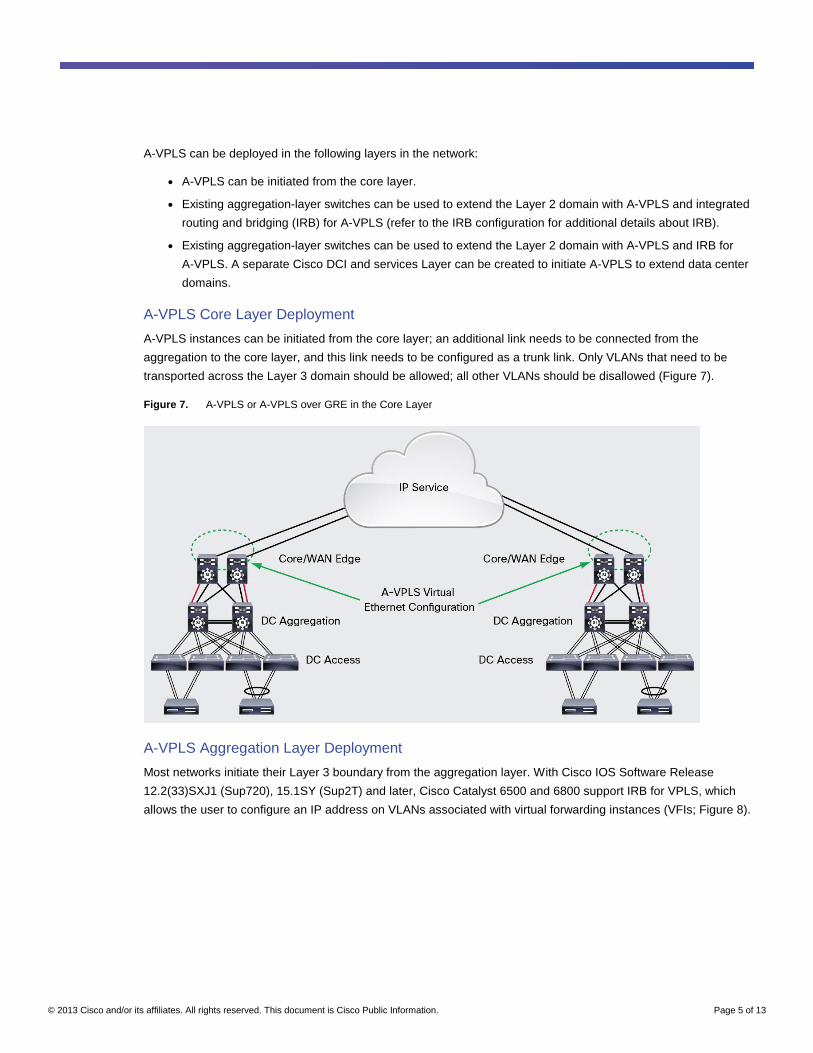
A-VPLS Core Layer Deployment
A-VPLS instances can be initiated from the core layer; an additional link needs to be connected from the
aggregation to the core layer, and this link needs to be configured as a trunk link. Only VLANs that need to be
transported across the Layer 3 domain should be allowed; all other VLANs should be disallowed (Figure 7).
Figure 7. A-VPLS or A-VPLS over GRE in the Core Layer
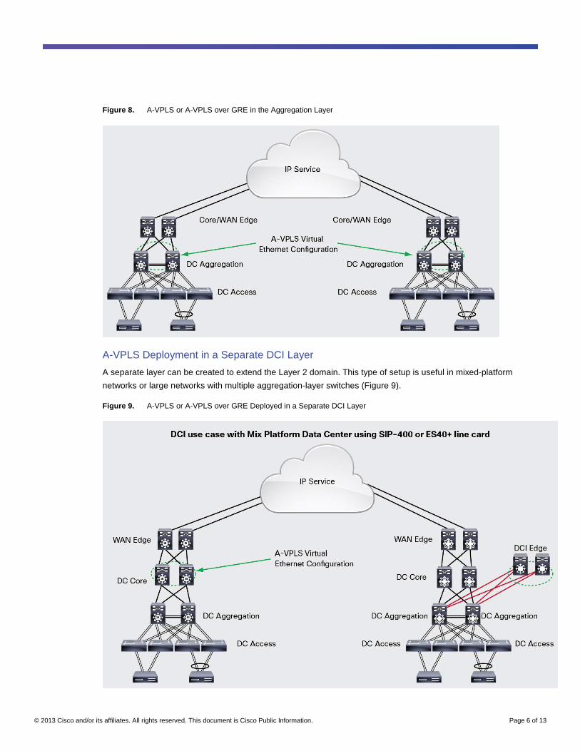
A-VPLS Aggregation Layer Deployment
Most networks initiate their Layer 3 boundary from the aggregation layer. With Cisco IOS Software Release
12.2(33)SXJ1 (Sup720), 15.1SY (Sup2T) and later, Cisco Catalyst 6500 and 6800 support IRB for VPLS, which
allows the user to configure an IP address on VLANs associated with virtual forwarding instances (VFIs; Figure 8).
© 2013 Cisco and/or its affiliates. All rights reserved. This document is Cisco Public Information. Page 6 of 13
Figure 8. A-VPLS or A-VPLS over GRE in the Aggregation Layer
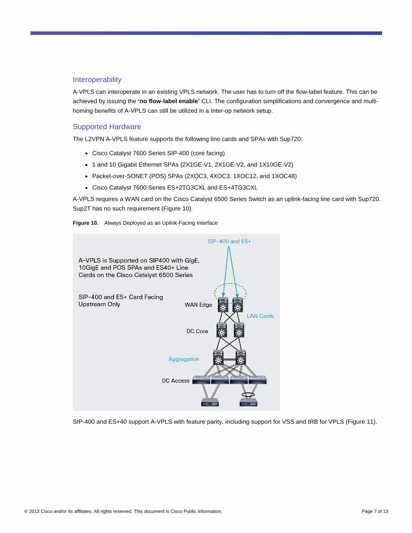
A-VPLS Deployment in a Separate DCI Layer
A separate layer can be created to extend the Layer 2 domain. This type of setup is useful in mixed-platform
networks or large networks with multiple aggregation-layer switches (Figure 9).
Figure 9. A-VPLS or A-VPLS over GRE Deployed in a Separate DCI Layer
© 2013 Cisco and/or its affiliates. All rights reserved. This document is Cisco Public Information. Page 7 of 13
Interoperability
A-VPLS can interoperate in an existing VPLS network. The user has to turn off the flow-label feature. This can be
achieved by issuing the ‘no flow-label enable’ CLI. The configuration simplifications and convergence and multi-
homing benefits of A-VPLS can still be utilized in a Inter-op network setup.
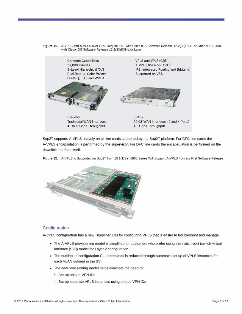
Supported Hardware
The L2VPN A-VPLS feature supports the following line cards and SPAs with Sup720:
● Cisco Catalyst 7600 Series SIP-400 (core facing)
● 1 and 10 Gigabit Ethernet SPAs (2X1GE-V1, 2X1GE-V2, and 1X10GE-V2)
● Packet-over-SONET (POS) SPAs (2XOC3, 4XOC3, 1XOC12, and 1XOC48)
● Cisco Catalyst 7600 Series ES+2TG3CXL and ES+4TG3CXL
A-VPLS requires a WAN card on the Cisco Catalyst 6500 Series Switch as an uplink-facing line card with Sup720.
Sup2T has no such requirement (Figure 10).
Figure 10. Always Deployed as an Uplink-Facing Interface
SIP-400 and ES+40 support A-VPLS with feature parity, including support for VSS and IRB for VPLS (Figure 11).
© 2013 Cisco and/or its affiliates. All rights reserved. This document is Cisco Public Information. Page 8 of 13
Figure 11. A-VPLS and A-VPLS over GRE Require ES+ with Cisco IOS Software Release 12.2(33)SXJ1 or Later or SIP-400 with Cisco IOS Software Release 12.2(33)SXI4a or Later
Sup2T supports A-VPLS natively on all line cards supported by the Sup2T platform. For CFC line cards the
A-VPLS encapsulation is performed by the supervisor. For DFC line cards the encapsulation is performed on the
downlink interface itself.
Figure 12. A-VPLS is Supported on Sup2T from 15.1(1)SY. 6800 Series Will Support A-VPLS from it’s First Software Release
Configuration
A-VPLS configuration has a new, simplified CLI for configuring VPLS that is easier to troubleshoot and manage.
● The A-VPLS provisioning model is simplified for customers who prefer using the switch-port (switch virtual
interface [SVI]) model for Layer 2 configuration.
● The number of configuration CLI commands is reduced through automatic set up of VPLS instances for
each VLAN defined in the SVI.
● The new provisioning model helps eliminate the need to: ◦ Set up unique VPN IDs ◦ Set up separate VPLS instances using unique VPN IDs
© 2013 Cisco and/or its affiliates. All rights reserved. This document is Cisco Public Information. Page 9 of 13
◦ Redefine peering provider-edge devices for each VPLS instance in cases in which the sets of peering
provider edge devices are the same for different VPLS instances ◦ Bind pseudowire to VLAN interfaces (with the Xconnect command on every VLAN interface)
A-VPLS Configuration Global MPLS and Pseudowire Class Configuration
!
mpls ip
mpls label protocol ldp
!
pseudowire-class cl1
encap mpls
load-balance flow (Enables load balancing on ECMPs)
flow-label enable (Enables the imposition and disposition of flow labels for the pseudowire)
!
port-channel load-balance src-mac
!
MPLS Egress Interface Configuration
!
interface TenGigabitEthernet1/1/3/0
ip address 10.1.1.1 255.255.255.0
mpls ip
!
New Virtual Ethernet Configuration interface virtual-ethernet 1 (Creates a virtual Ethernet interface and enters interface configuration mode)
transport vpls mesh (Create a full mesh of pseudowires and enters VPLS transport mode)
neighbor 10.2.2.2 pw-class cl1 (Specifies the PE routers to be used in the pseudowire)
neighbor 10.3.3.3 pw-class cl1
switchport
switchport mode trunk
switchport trunk allowed vlan 10, 20
Integrated Routing and Bridging Configuration A-VPLS and A-VPLS over GRE with Integrated Routing and Bridging provide the flexibility to use a single device
to configure A-VPLS Bridging and regular SVI Routing. This is especially useful for customers who do not wish to
extend any VLANs to the Core or WAN layer and terminate all Layer 2 traffic in the aggregation layer itself. This
type of configuration also allows for Multi-Tenancy deployments with A-VPLS providing Layer 2 and MPLS VPN
(VRF) providing Layer 3 segmentation and virtualization.
!
Interface VLAN 10
© 2013 Cisco and/or its affiliates. All rights reserved. This document is Cisco Public Information. Page 10 of 13
ip vrf forwarding vrf_1
ip address 12.12.12.1 255.255.255.0 (with IRB, user can configure an IP address on an SVI associated with a VPLS PW)
!
Interface VLAN 20
ip vrf forwarding vrf_2
ip address 12.12.11.1 255.255.255.0
end
A-VPLS over GRE Configuration
A-VPLS over GRE is a key requirement for customers who want to encrypt Layer 2 traffic between 2 or more sites.
A-VPLS over GRE is also used for customers who do not wish to move to a MPLS core network or use it as
phased migration step towards an MPLS network.
Global MPLS and Pseudowire Class Configuration !
mpls ip
mpls label protocol ldp
!
pseudowire-class cl1
encap mpls
load-balance flow
flow-label enable
!
port-channel load-balance src-mac
!
Load-Balancing On Sup2T Based Platforms:
The A-VPLS on Earl8 also allows user to configure the number of flow labels and adjacencies to use to setup the
final set of Egress adjacencies that will be programmed for each pseudowire.
The below logic enhances the number of flow-label to be used for each path and thus enhance load-balancing in
the core.
© 2013 Cisco and/or its affiliates. All rights reserved. This document is Cisco Public Information. Page 11 of 13
CLI:
platform vpls pseudowire maximum adjacency <2-16>
platform vpls pseudowire maximum flow-label <2-16>
Egress Physical and GRE Tunnel Configuration
int tunnel 1
tunnel mode gre ip
mpls ip (MPLS enabled only on tunnel interface)
tunnel source 10.1.1.1 (Loopback interfaces with /32 addressing is recommended)
tunnel destination 10.2.2.2
!
int tunnel 2
tunnel mode gre ip
mpls ip
tunnel source 10.1.1.2 (Should use unique source IP for each tunnel to ensure hardware switching for GRE)
tunnel destination 10.3.3.3
!
interface TenGigabitEthernet1/1/3/0
ip address 10.1.1.1 255.255.255.0
!
New Virtual Ethernet Configuration interface virtual-ethernet 1
transport vpls mesh
neighbor 10.2.2.2 pw-class cl1
neighbor 10.3.3.3 pw-class cl1
switchport
switchport mode trunk
switchport trunk allowed vlan 10, 20
ip route 10.2.2.2 255.255.255.255 Tunnel1 (Static routes are used to map the remote LDP neighbor through the tunnel interfaces)
ip route 10.2.2.2 255.255.255.255 Tunnel2
!
© 2013 Cisco and/or its affiliates. All rights reserved. This document is Cisco Public Information. Page 12 of 13
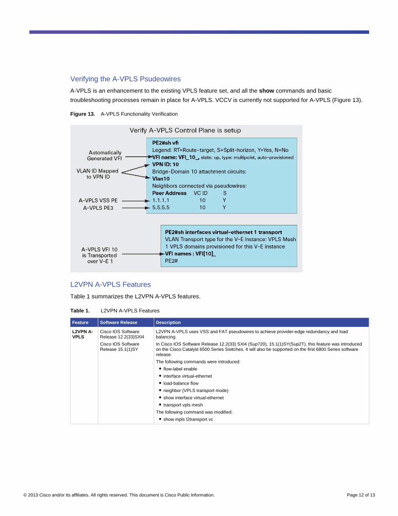
Verifying the A-VPLS Psudeowires
A-VPLS is an enhancement to the existing VPLS feature set, and all the show commands and basic
troubleshooting processes remain in place for A-VPLS. VCCV is currently not supported for A-VPLS (Figure 13).
Figure 13. A-VPLS Functionality Verification
L2VPN A-VPLS Features
Table 1 summarizes the L2VPN A-VPLS features.
Table 1. L2VPN A-VPLS Features
Feature Software Release Description
L2VPN A-VPLS
Cisco IOS Software Release 12.2(33)SXI4
Cisco IOS Software Release 15.1(1)SY
L2VPN A-VPLS uses VSS and FAT pseudowires to achieve provider-edge redundancy and load balancing.
In Cisco IOS Software Release 12.2(33) SXI4 (Sup720), 15.1(1)SY(Sup2T), this feature was introduced on the Cisco Catalyst 6500 Series Switches. It will also be supported on the first 6800 Series software release.
The following commands were introduced:
● flow-label enable
● interface virtual-ethernet
● load-balance flow
● neighbor (VPLS transport mode)
● show interface virtual-ethernet
● transport vpls mesh
The following command was modified:
● show mpls l2transport vc
© 2013 Cisco and/or its affiliates. All rights reserved. This document is Cisco Public Information. Page 13 of 13
Conclusion
The Cisco A-VPLS feature provides simple new commands that deliver powerful traffic flow load-balancing
functions in IP and IP/MPLS networks. Load balancing in the network, integrated with Cisco Catalyst 6500 and
6800 Series Switches, optimizes resource utilization, improving customers' return on investment (ROI). It also
facilitates recovery from service interruptions, increasing the availability of the protected services. A-VPLS benefits
service providers and enterprises by optimizing bandwidth utilization in many deployment scenarios, including
Cisco DCI applications for enterprises and for service provider-managed services.
For More Information
● Cisco DCI: http://www.cisco.com/go/dci.
● Cisco VPLS white papers:
http://www.cisco.com/en/US/products/ps6648/products_ios_protocol_option_home.html.
Printed in USA C07-647422-01 11/13