Advanced video converter 4K MULTI-CAMERA UNIT KMU-100
47
Advanced video converter 4K MULTI-CAMERA UNIT KMU-100 User guide www.datavideo.com www.kmu.hdpmedia.eu
Transcript of Advanced video converter 4K MULTI-CAMERA UNIT KMU-100
Advanced video converter
4K MULTI-CAMERA UNIT
KMU-100
User guide
www.datavideo.com www.kmu.hdpmedia.eu
2
KMU-100 4K MULTI-CAMERA UNIT
� Table of contents:
System description 3
Functions and features of KMU-100 . . . . . . . . . . . . . . . . . . . . . . . . . . . . . . . . 4
How does KMU-100 operate? . . . . . . . . . . . . . . . . . . . . . . . . . . . . . . . . . . . . 4
Capabilities, functionalities and applications 5
Image production and postproduction . . . . . . . . . . . . . . . . . . . . . . . . . . . . . . 5
Creating a video wall . . . . . . . . . . . . . . . . . . . . . . . . . . . . . . . . . . . . . . . . . 6
The highest quality in security systems . . . . . . . . . . . . . . . . . . . . . . . . . . . . . 8
Trigger – connecting a device triggering a specific KMU-100 4K . . . . . . . . . . . . . 9
Joystick – additional possibilities of controlling your virtual camera . . . . . . . . . . 10
DV Link 11
Control application 15
App’s windows description: Connections . . . . . . . . . . . . . . . . . . . . . . . . . . . . 15
App’s windows description: Channel A and Channel B . . . . . . . . . . . . . . . . . . . . 25
Hard reset . . . . . . . . . . . . . . . . . . . . . . . . . . . . . . . . . . . . . . . . . . . . . . . 35
Camera Control Unit RMC 185 with Joystick 36
Technical parameters 43
Service & Support 47
3
KMU-100 4K MULTI-CAMERA UNIT
System description
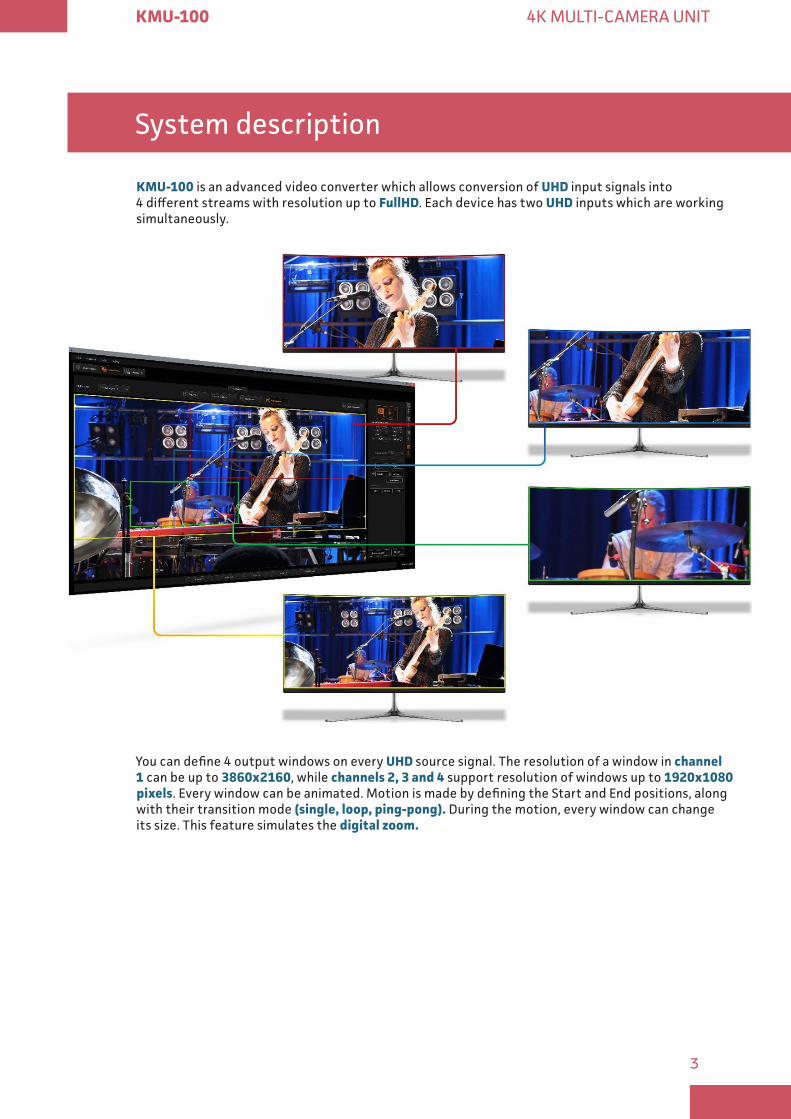
KMU-100 is an advanced video converter which allows conversion of UHD input signals into 4 different streams with resolution up to FullHD. Each device has two UHD inputs which are working simultaneously.
You can define 4 output windows on every UHD source signal. The resolution of a window in channel 1 can be up to 3860x2160, while channels 2, 3 and 4 support resolution of windows up to 1920x1080 pixels. Every window can be animated. Motion is made by defining the Start and End positions, along with their transition mode (single, loop, ping-pong) During the motion, every window can change its size. This feature simulates the digital zoom

4
KMU-100 4K MULTI-CAMERA UNIT
� Functions and features of KMU-100
KMU-100 is an advanced video converter that allows processing and conversion of UHD signals (3840x2160), for example: 12G SDI or HDMI 2 0 into four or eight different high-quality streams, at resolutions up to FullHD. KMU has got two independent conversion channels!
This enables simultaneous and parallel processing of two UHD signal sources – 3840x2160, the input signals are converted into eight 3G SDI outputs, which can be additionally synchronized to a Genlock input.
This solution is ideal for professionals who deal with production and broadcasting of video materials using a variety of sources and signal types. It is perfect to apply both on the set and during the life coverage of events.
In addition, KMU-100 converter is really easy to use. A complete software is provided with the device, and the control over all its functions and parameters is exercised via a LAN connected computer with the application installed. The small size of the device, its user-friendly interface, and the support with DV Link platform also positively influence converter’s usability and user experience.
� How does KMU-100 operate?
KMU-100 is able to simultaneously convert signals from two video inputs with resolutions up to UHD (3840x2160). It supports a variety of video formats and enables the connection of signal sources in the form of SDI and HDMI, including 12G SDI and HDMI 2 0 technologies.
The output signals are as many as 8 channels. They are created for each channel by indicating an active area from the area of the device’s input signals. These areas are defined in the application installed on a computer connected to the KMU-100 device via LAN.
The definition of the area, which will determine the output content, is nothing more than a simple positioning of a rectangle in the MultiViewer preview for a given channel, and that, of course, against the background of the device’s input signal. Each of the rectangles is marked with a different border color. For one of the channels you can scale the signal from full 4K resolution to FullHD, and there is up and down scaling (zoom) possible for all other outputs. The output area (position of each rectangle) may be a function of a variable, which means in constant motion. For each rectangle, there are simple motions available, you just need to select one of the available modes. The scope of all the settings and the end positions are defined in the application in a user friendly interface.
The areas defined by the rectangles create 8 SDI outputs (2 x 4 or 1 x 8). Two multiviewer (HDMI or SDI) outputs are used for preview and for device’s configuration.
KMU-100 means multiple applications and uses, as this device allows for a variety of effects that will satisfy every professional engaged in production, broadcasting and also events’ live coverage with the use of audiovisual materials!
5
KMU-100 4K MULTI-CAMERA UNIT
Capabilities, functionalities and applications
KMU-100 – is a bridge connecting 4K technologies with current video systems solutions. This device has a very wide range of applications in virtually every area where the high quality image preview is required, – like sporting events, industrial automation, visual effects used during all kinds of live events or postproduction.
Below, you can find several applications shown as examples of possible uses of our device:
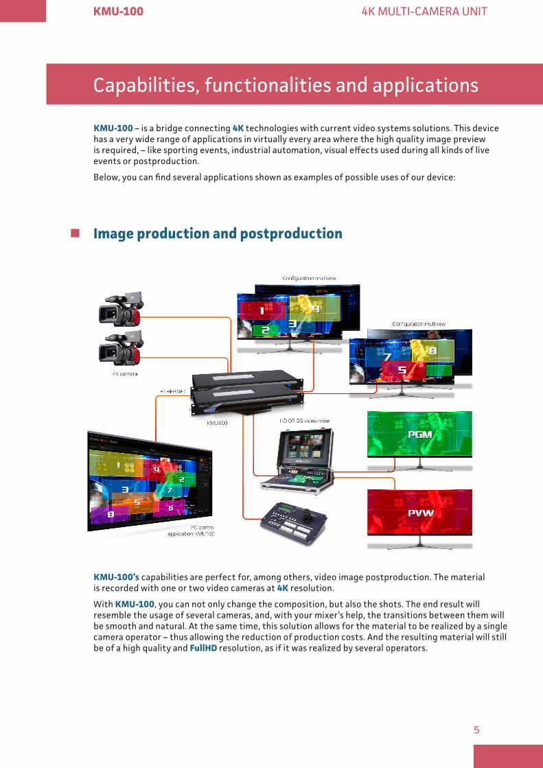
� Image production and postproduction
KMU-100’s capabilities are perfect for, among others, video image postproduction. The material is recorded with one or two video cameras at 4K resolution.
With KMU-100, you can not only change the composition, but also the shots. The end result will resemble the usage of several cameras, and, with your mixer’s help, the transitions between them will be smooth and natural. At the same time, this solution allows for the material to be realized by a single camera operator – thus allowing the reduction of production costs. And the resulting material will still be of a high quality and FullHD resolution, as if it was realized by several operators.
6
KMU-100 4K MULTI-CAMERA UNIT
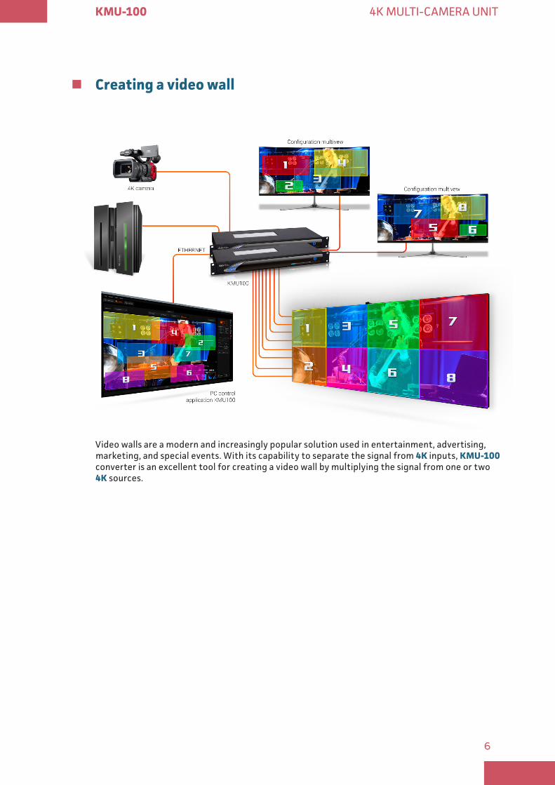
� Creating a video wall
Video walls are a modern and increasingly popular solution used in entertainment, advertising, marketing, and special events. With its capability to separate the signal from 4K inputs, KMU-100 converter is an excellent tool for creating a video wall by multiplying the signal from one or two 4K sources.
7
KMU-100 4K MULTI-CAMERA UNIT
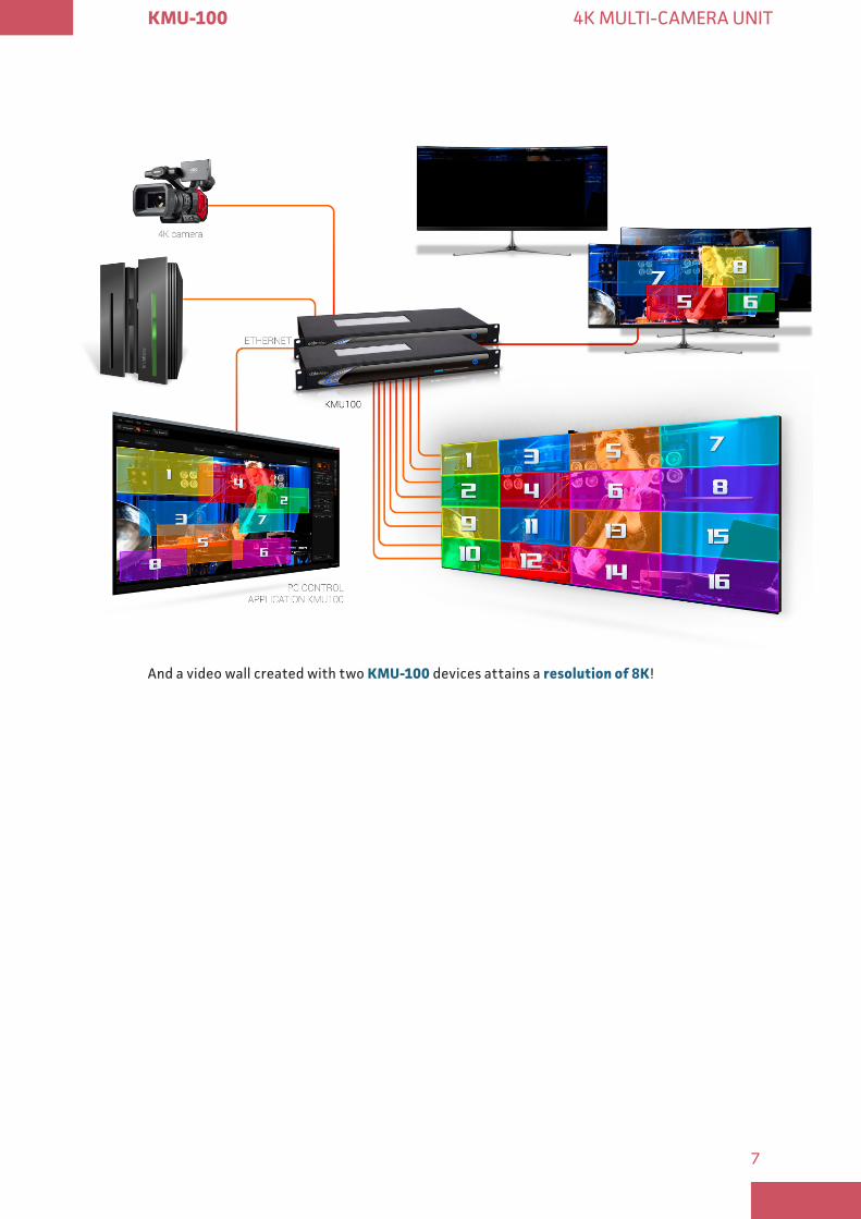
And a video wall created with two KMU-100 devices attains a resolution of 8K!
8
KMU-100 4K MULTI-CAMERA UNIT
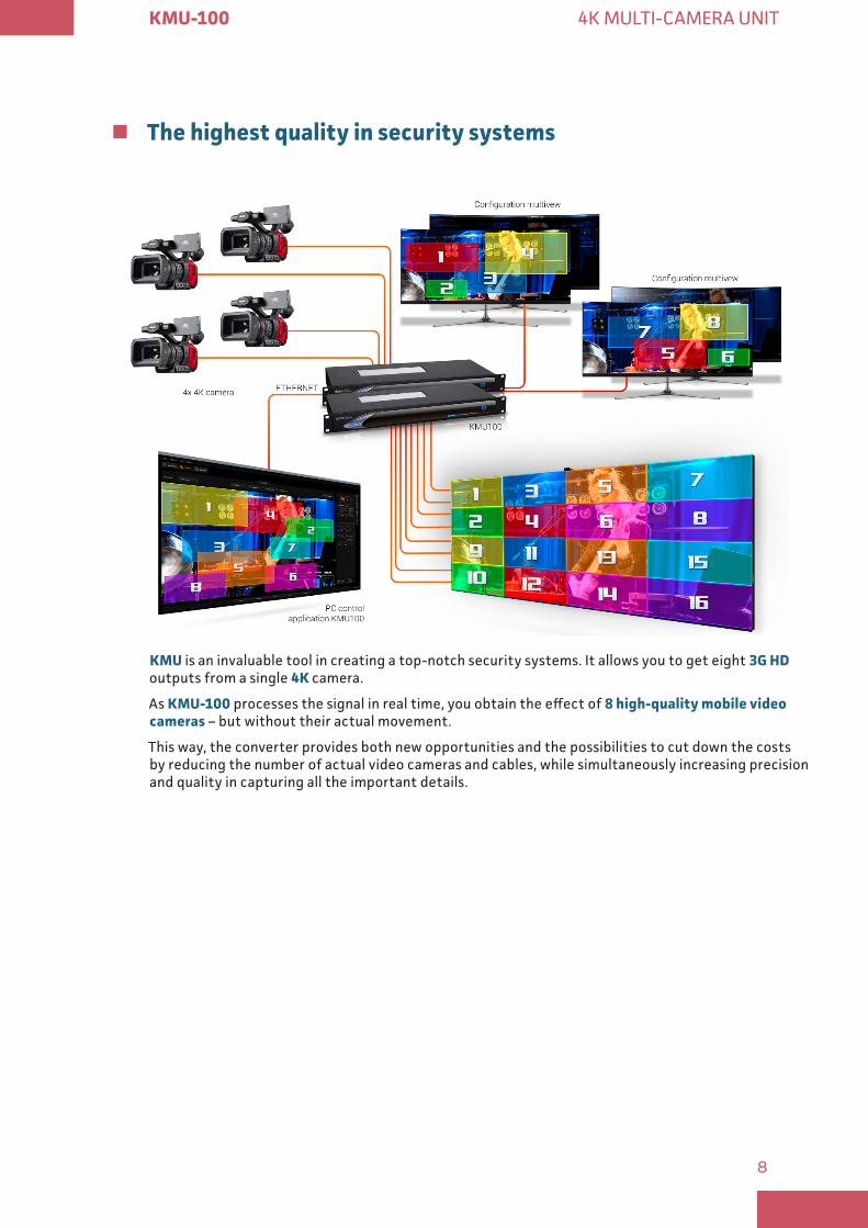
� The highest quality in security systems
KMU is an invaluable tool in creating a top-notch security systems. It allows you to get eight 3G HD outputs from a single 4K camera.
As KMU-100 processes the signal in real time, you obtain the effect of 8 high-quality mobile video cameras – but without their actual movement.
This way, the converter provides both new opportunities and the possibilities to cut down the costs by reducing the number of actual video cameras and cables, while simultaneously increasing precision and quality in capturing all the important details.
9
KMU-100 4K MULTI-CAMERA UNIT
� Trigger – connecting a device triggering a specific KMU-100 4K
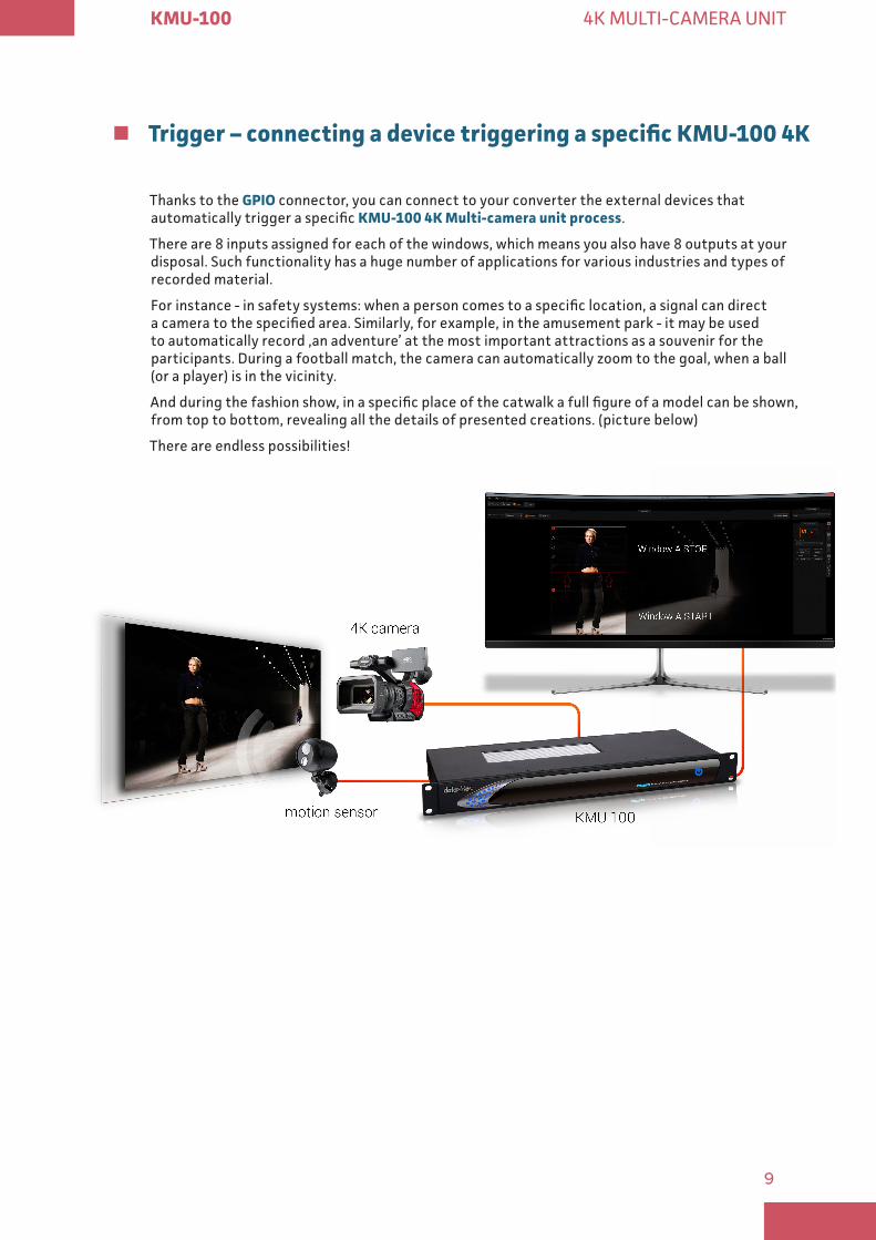
Thanks to the GPIO connector, you can connect to your converter the external devices that automatically trigger a specific KMU-100 4K Multi-camera unit process.
There are 8 inputs assigned for each of the windows, which means you also have 8 outputs at your disposal. Such functionality has a huge number of applications for various industries and types of recorded material.
For instance - in safety systems: when a person comes to a specific location, a signal can direct a camera to the specified area. Similarly, for example, in the amusement park - it may be used to automatically record ‚an adventure’ at the most important attractions as a souvenir for the participants. During a football match, the camera can automatically zoom to the goal, when a ball (or a player) is in the vicinity.
And during the fashion show, in a specific place of the catwalk a full figure of a model can be shown, from top to bottom, revealing all the details of presented creations. (picture below)
There are endless possibilities!
10
KMU-100 4K MULTI-CAMERA UNIT
� Joystick – additional possibilities of controlling your virtual camera
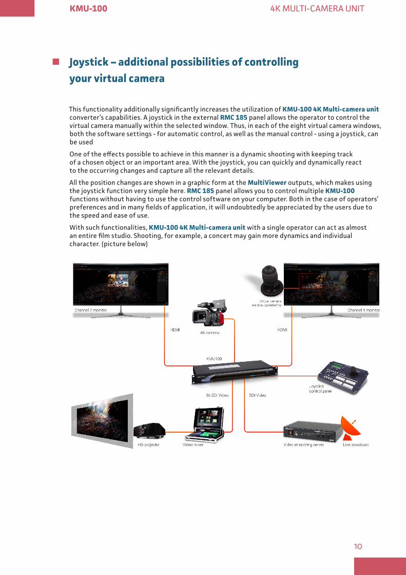
This functionality additionally significantly increases the utilization of KMU-100 4K Multi-camera unit converter’s capabilities. A joystick in the external RMC 185 panel allows the operator to control the virtual camera manually within the selected window. Thus, in each of the eight virtual camera windows, both the software settings - for automatic control, as well as the manual control - using a joystick, can be used
One of the effects possible to achieve in this manner is a dynamic shooting with keeping track of a chosen object or an important area. With the joystick, you can quickly and dynamically react to the occurring changes and capture all the relevant details.
All the position changes are shown in a graphic form at the MultiViewer outputs, which makes using the joystick function very simple here. RMC 185 panel allows you to control multiple KMU-100 functions without having to use the control software on your computer. Both in the case of operators’ preferences and in many fields of application, it will undoubtedly be appreciated by the users due to the speed and ease of use.
With such functionalities, KMU-100 4K Multi-camera unit with a single operator can act as almost an entire film studio. Shooting, for example, a concert may gain more dynamics and individual character. (picture below)
11
KMU-100 4K MULTI-CAMERA UNIT
DV Link
A platform that unites all!
DV Link platform is a very simple and useful software developed for configuration, diagnostics and control of multiple devices (for example four KMU-100 converters) communicating through a common DVIP protocol.
A camera operator or operators can easily change the functions of each of the visible devices or a group by triggering the pre-defined presets, without the need to use the main application for KMU management. This way, DV Link application allows for quick reconfiguration of the equipment, for example for a specific or a following task.
DV Link platform connects multiple devices to control them in a single application.
We invite all the KMU-100 users to download the DV Link application for free.
The technical specifications, manual and the download link can be found on a subpage www.kmu.hdpmedia.eu.
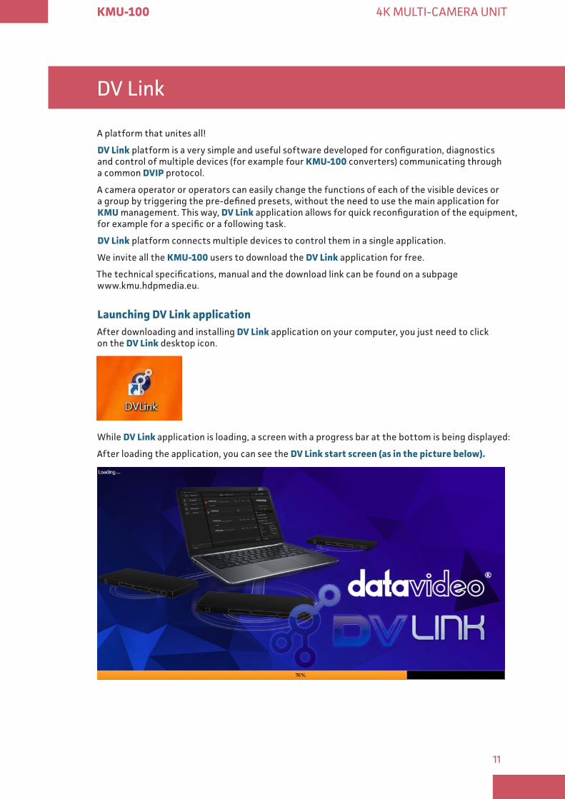
Launching DV Link applicationAfter downloading and installing DV Link application on your computer, you just need to click on the DV Link desktop icon.
While DV Link application is loading, a screen with a progress bar at the bottom is being displayed:
After loading the application, you can see the DV Link start screen (as in the picture below)
12
KMU-100 4K MULTI-CAMERA UNIT
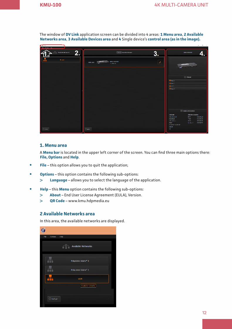
The window of DV Link application screen can be divided into 4 areas: 1 Menu area, 2 Available Networks area, 3 Available Devices area and 4 Single device’s control area (as in the image)
1 Menu areaA Menu bar is located in the upper left corner of the screen. You can find three main options there: File, Options and Help.
y File – this option allows you to quit the application;
y Options – this option contains the following sub-options:
> Language – allows you to select the language of the application.
y Help – this Menu option contains the following sub-options:
> About – End User License Agreement (EULA), Version.
> QR Code – www.kmu.hdpmedia.eu
2 Available Networks areaIn this area, the available networks are displayed.
13
KMU-100 4K MULTI-CAMERA UNIT
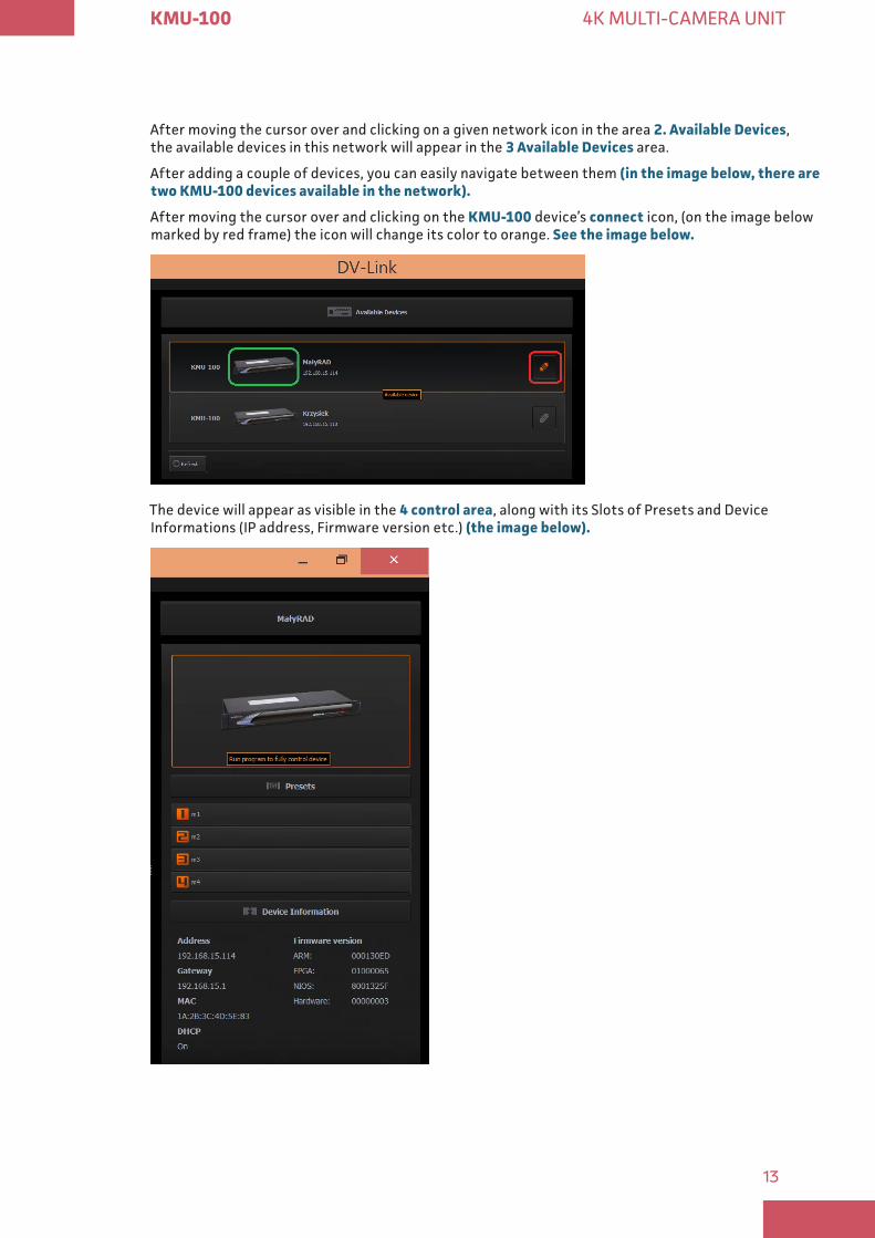
After moving the cursor over and clicking on a given network icon in the area 2 Available Devices, the available devices in this network will appear in the 3 Available Devices area.
After adding a couple of devices, you can easily navigate between them (in the image below, there are two KMU-100 devices available in the network)
After moving the cursor over and clicking on the KMU-100 device’s connect icon, (on the image below marked by red frame) the icon will change its color to orange. See the image below
The device will appear as visible in the 4 control area, along with its Slots of Presets and Device Informations (IP address, Firmware version etc.) (the image below)
14
KMU-100 4K MULTI-CAMERA UNIT
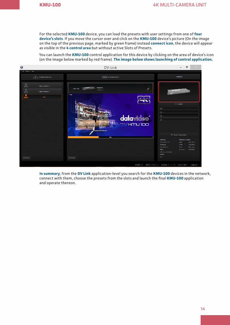
For the selected KMU-100 device, you can load the presets with user settings from one of four device’s slots. If you move the cursor over and click on the KMU-100 device’s picture (On the image on the top of the previous page, marked by green frame) instead connect icon, the device will appear as visible in the 4 control area but without active Slots of Presets.
You can launch the KMU-100 control application for this device by clicking on the area of device’s icon (on the image below marked by red frame). The image below shows launching of control application
In summary, from the DV Link application-level you search for the KMU-100 devices in the network, connect with them, choose the presets from the slots and launch the final KMU-100 application and operate thereon.
15
KMU-100 4K MULTI-CAMERA UNIT
Control application
It allows the device’s configuration and saving presets in the device’s internal memory.
� App’s windows description: Connections
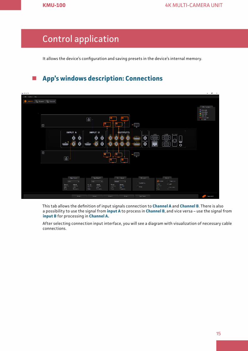
This tab allows the definition of input signals connection to Channel A and Channel B. There is also a possibility to use the signal from input A to process in Channel B, and vice versa – use the signal from input B for processing in Channel A
After selecting connection input interface, you will see a diagram with visualization of necessary cable connections.
16
KMU-100 4K MULTI-CAMERA UNIT
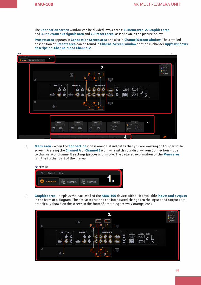
The Connection screen window can be divided into 4 areas: 1 Menu area; 2 Graphics area and 3 Input/output signals area and 4 Presets area, as is shown in the picture below.
Presets area appears in Connection Screen area and also in Channel Screen window. The detailed description of Presets area can be found in Channel Screen window section in chapter App’s windows description: Channel 1 and Channel 2.
1. Menu area – when the Connection icon is orange, it indicates that you are working on this particular screen. Pressing the Channel A or Channel B icon will switch your display from Connection mode to channel A or channel B settings (processing) mode. The detailed explanation of the Menu area is in the further part of the manual.
2. Graphics area – displays the back wall of the KMU-100 device with all its available inputs and outputs in the form of a diagram. The active status and the introduced changes to the inputs and outputs are graphically shown on the screen in the form of emerging arrows / orange icons.
17
KMU-100 4K MULTI-CAMERA UNIT
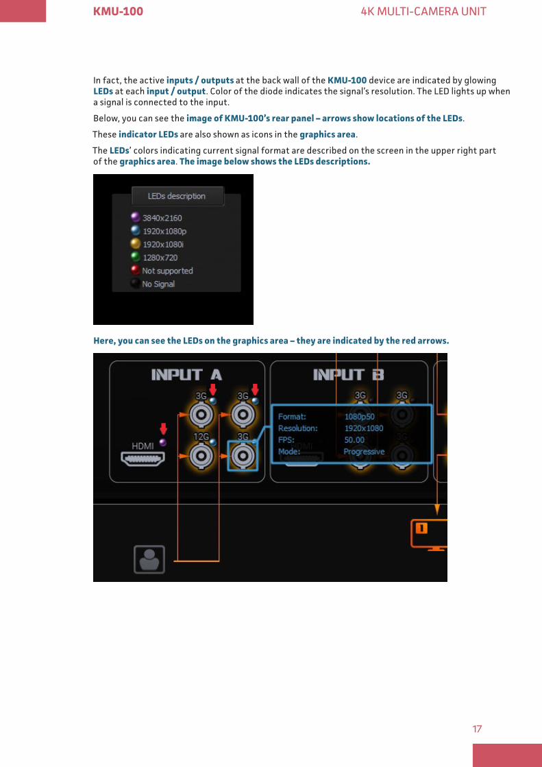
In fact, the active inputs / outputs at the back wall of the KMU-100 device are indicated by glowing LEDs at each input / output. Color of the diode indicates the signal’s resolution. The LED lights up when a signal is connected to the input.
Below, you can see the image of KMU-100’s rear panel – arrows show locations of the LEDs.
These indicator LEDs are also shown as icons in the graphics area.
The LEDs’ colors indicating current signal format are described on the screen in the upper right part of the graphics area. The image below shows the LEDs descriptions
Here, you can see the LEDs on the graphics area – they are indicated by the red arrows
18
KMU-100 4K MULTI-CAMERA UNIT
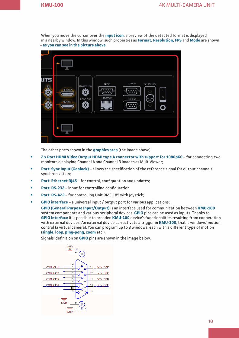
When you move the cursor over the input icon, a preview of the detected format is displayed in a nearby window. In this window, such properties as Format, Resolution, FPS and Mode are shown
– as you can see in the picture above.
The other ports shown in the graphics area (the image above):
y 2 x Port HDMI Video Output HDMI type A connector with support for 1080p60 – for connecting two monitors displaying Channel A and Channel B images as MultiViewer;
y Port: Sync Input (Genlock) – allows the specification of the reference signal for output channels synchronization;
y Port: Ethernet RJ45 – for control, configuration and updates;
y Port: RS-232 – input for controlling configuration;
y Port: RS-422 – for controlling Unit RMC 185 with Joystick;
y GPIO interface – a universal input / output port for various applications;GPIO (General Purpose Input/Output) is an interface used for communication between KMU-100 system components and various peripheral devices. GPIO pins can be used as inputs. Thanks to GPIO Interface it is possible to broaden KMU-100 device’s functionalities resulting from cooperation with external devices. An external device can activate a trigger in KMU-100, that is windows’ motion control (a virtual camera). You can program up to 8 windows, each with a different type of motion (single, loop, ping-pong, zoom etc.).Signals’ definition on GPIO pins are shown in the image below.

19
KMU-100 4K MULTI-CAMERA UNIT
GPI diagram: Connecting a transistor and electrical parameters. See the image below.
y DC power supply socket
3. Input/output signals area – allows you to configure the KMU-100 device: setting the inputs’ signal, setting the output signal, operate channels synchronization (Genlock) and Multiviewer monitors’ settings.
Setting the input’s signalYou can choose the input signal options from the drop-down lists below the Signal Input A and Signal Input B icons, as described below.
The Signal Input A drop-down list is shown in the image below:
There are 4 Signal Input A configuration options to choose from: 4x SDI, 1x SDI, HDMI and Input Signal B
20
KMU-100 4K MULTI-CAMERA UNIT
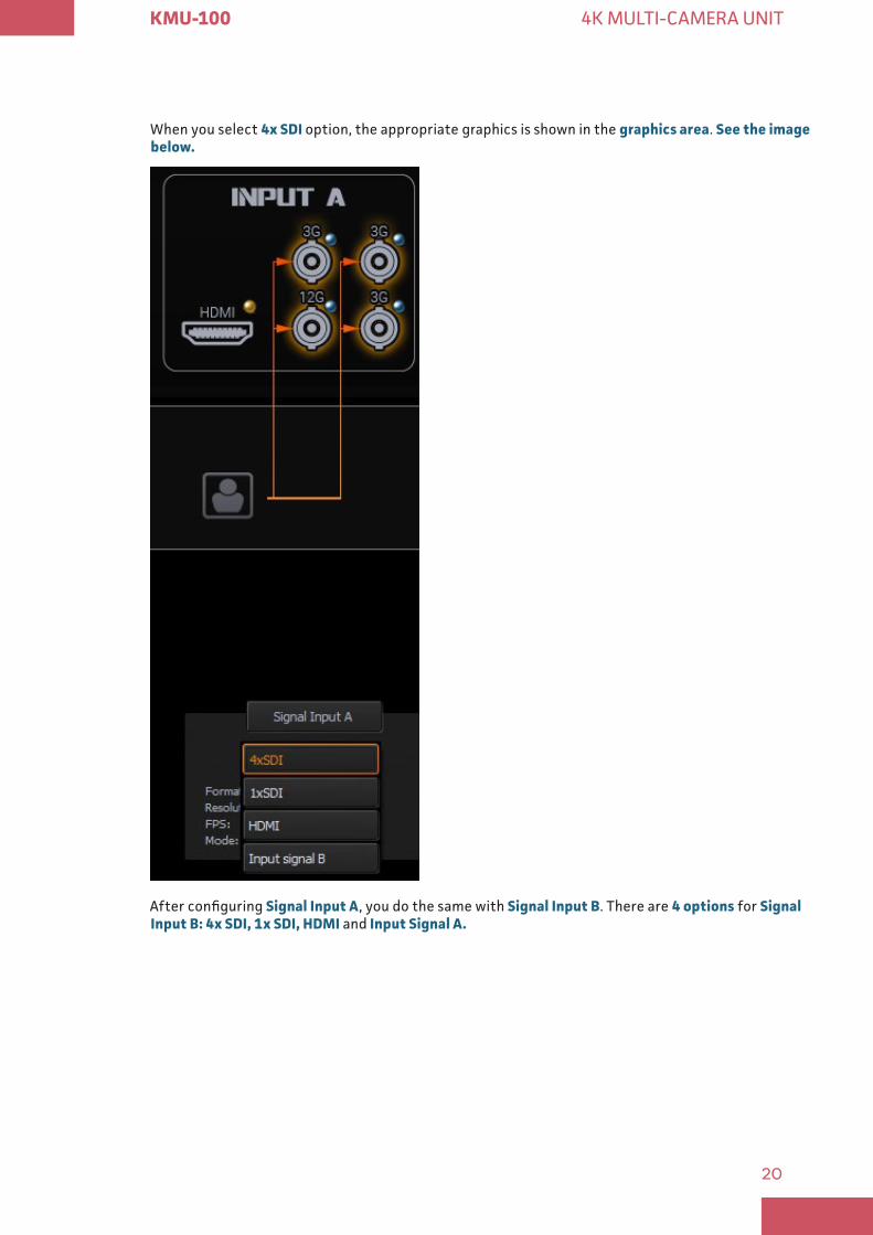
When you select 4x SDI option, the appropriate graphics is shown in the graphics area. See the image below
After configuring Signal Input A, you do the same with Signal Input B. There are 4 options for Signal Input B: 4x SDI, 1x SDI, HDMI and Input Signal A
21
KMU-100 4K MULTI-CAMERA UNIT
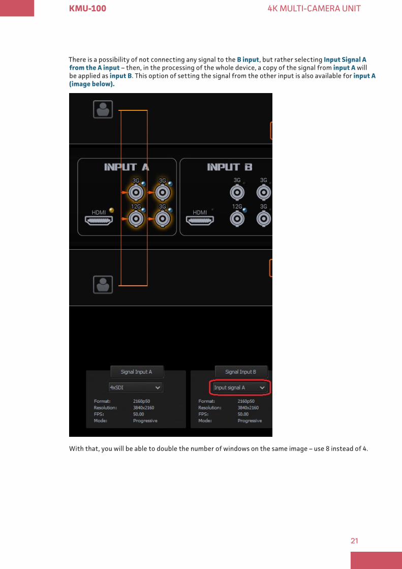
There is a possibility of not connecting any signal to the B input, but rather selecting Input Signal A from the A input – then, in the processing of the whole device, a copy of the signal from input A will be applied as input B. This option of setting the signal from the other input is also available for input A (image below)
With that, you will be able to double the number of windows on the same image – use 8 instead of 4.
22
KMU-100 4K MULTI-CAMERA UNIT
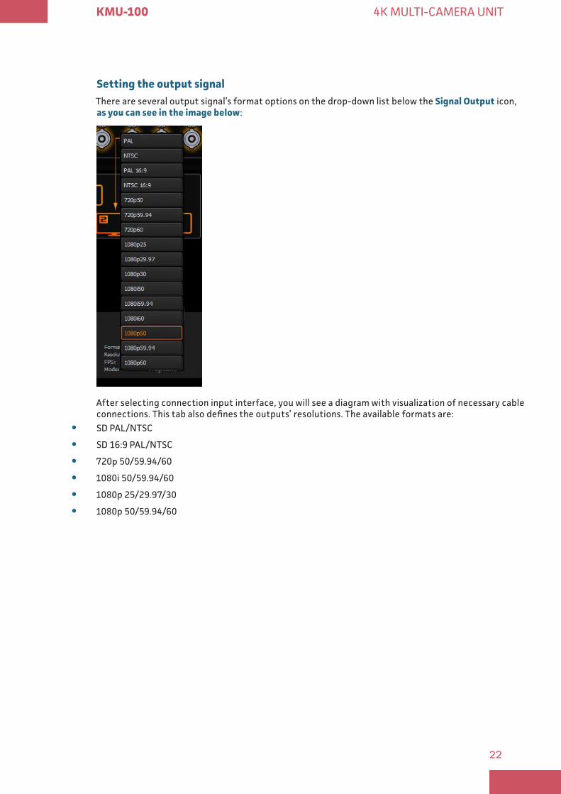
Setting the output signalThere are several output signal’s format options on the drop-down list below the Signal Output icon, as you can see in the image below:
After selecting connection input interface, you will see a diagram with visualization of necessary cable connections. This tab also defines the outputs’ resolutions. The available formats are:
y SD PAL/NTSC
y SD 16:9 PAL/NTSC
y 720p 50/59.94/60
y 1080i 50/59.94/60
y 1080p 25/29.97/30
y 1080p 50/59.94/60
23
KMU-100 4K MULTI-CAMERA UNIT
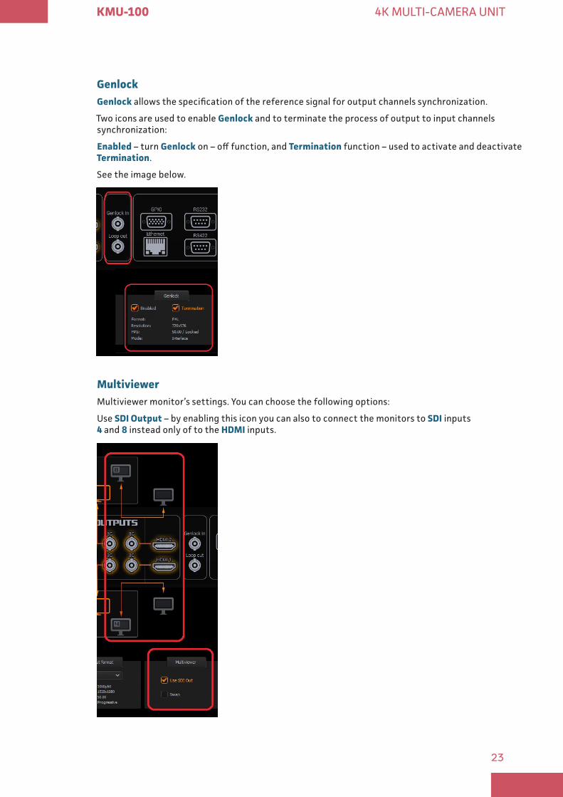
GenlockGenlock allows the specification of the reference signal for output channels synchronization.
Two icons are used to enable Genlock and to terminate the process of output to input channels synchronization:
Enabled – turn Genlock on – off function, and Termination function – used to activate and deactivate Termination.
See the image below.
Multiviewer Multiviewer monitor’s settings. You can choose the following options:
Use SDI Output – by enabling this icon you can also to connect the monitors to SDI inputs 4 and 8 instead only of to the HDMI inputs.
24
KMU-100 4K MULTI-CAMERA UNIT
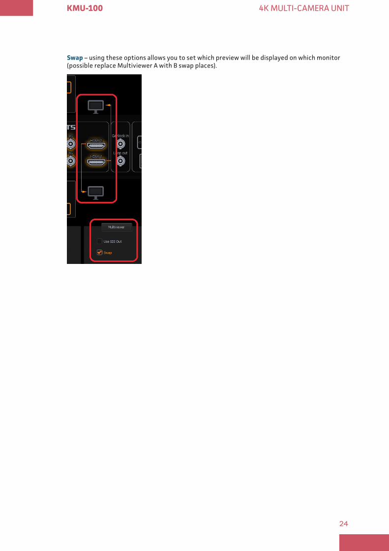
Swap – using these options allows you to set which preview will be displayed on which monitor (possible replace Multiviewer A with B swap places).
25
KMU-100 4K MULTI-CAMERA UNIT
� App’s windows description: Channel A and Channel B
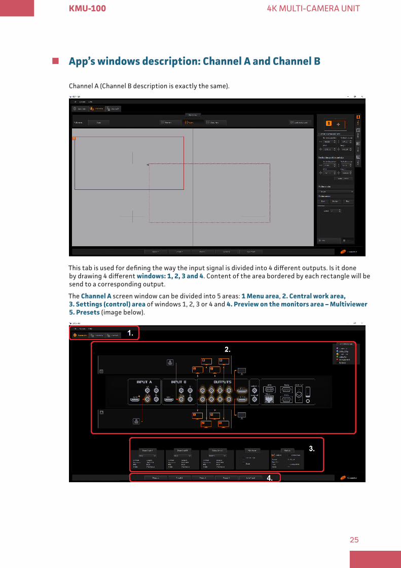
Channel A (Channel B description is exactly the same).
This tab is used for defining the way the input signal is divided into 4 different outputs. Is it done by drawing 4 different windows: 1, 2, 3 and 4. Content of the area bordered by each rectangle will be send to a corresponding output.
The Channel A screen window can be divided into 5 areas: 1 Menu area, 2 Central work area, 3 Settings (control) area of windows 1, 2, 3 or 4 and 4 Preview on the monitors area – Multiviewer 5 Presets (image below).
26
KMU-100 4K MULTI-CAMERA UNIT
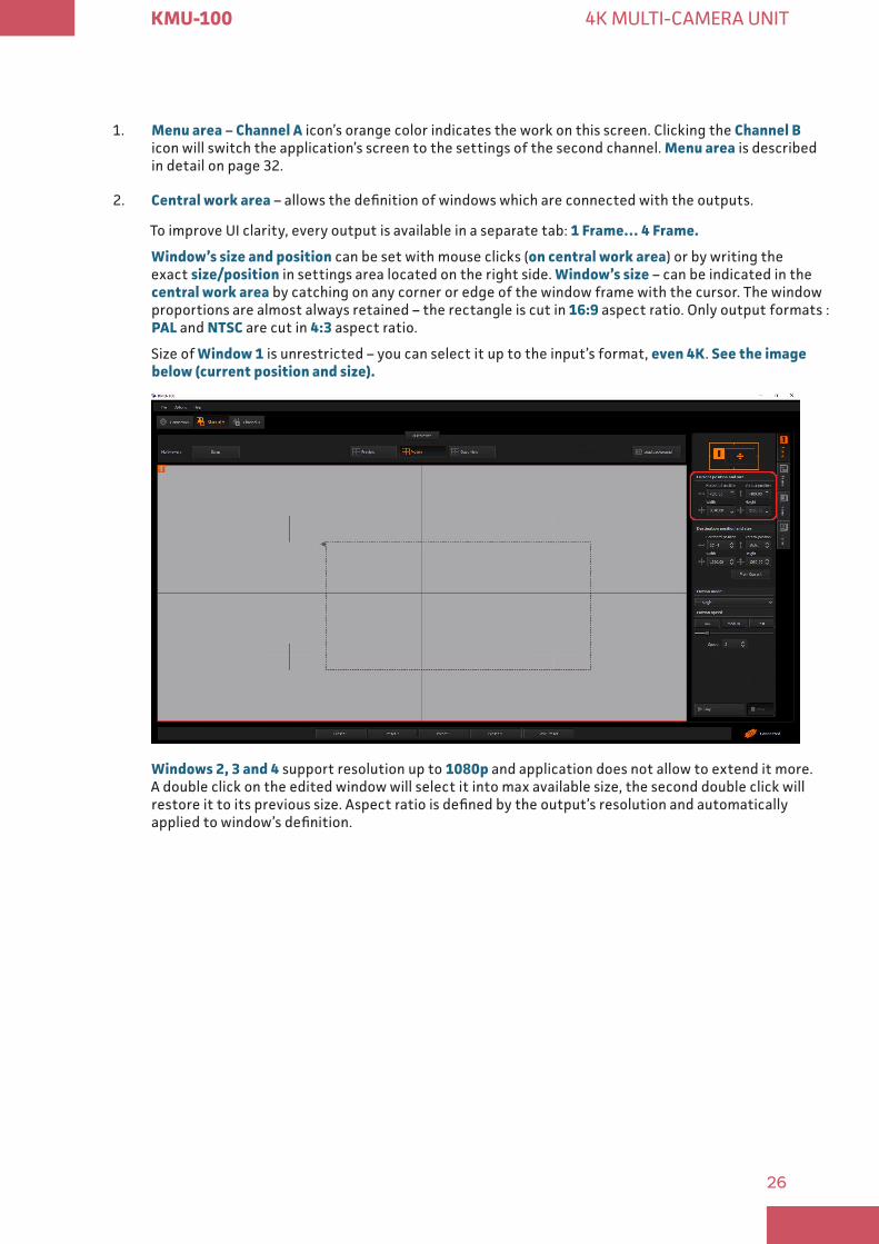
1. Menu area – Channel A icon’s orange color indicates the work on this screen. Clicking the Channel B icon will switch the application’s screen to the settings of the second channel. Menu area is described in detail on page 32.
2. Central work area – allows the definition of windows which are connected with the outputs.
To improve UI clarity, every output is available in a separate tab: 1 Frame… 4 Frame
Window’s size and position can be set with mouse clicks (on central work area) or by writing the exact size/position in settings area located on the right side. Window’s size – can be indicated in the central work area by catching on any corner or edge of the window frame with the cursor. The window proportions are almost always retained – the rectangle is cut in 16:9 aspect ratio. Only output formats : PAL and NTSC are cut in 4:3 aspect ratio.
Size of Window 1 is unrestricted – you can select it up to the input’s format, even 4K. See the image below (current position and size)
Windows 2, 3 and 4 support resolution up to 1080p and application does not allow to extend it more. A double click on the edited window will select it into max available size, the second double click will restore it to its previous size. Aspect ratio is defined by the output’s resolution and automatically applied to window’s definition.
27
KMU-100 4K MULTI-CAMERA UNIT
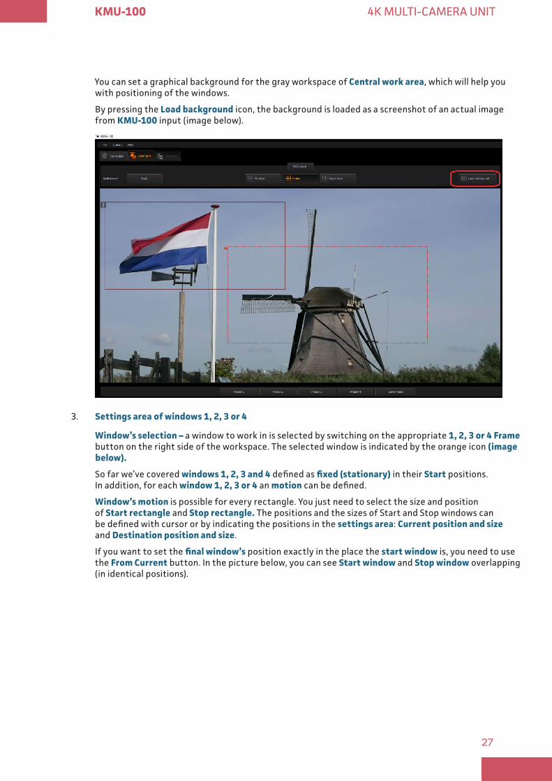
You can set a graphical background for the gray workspace of Central work area, which will help you with positioning of the windows.
By pressing the Load background icon, the background is loaded as a screenshot of an actual image from KMU-100 input (image below).
3. Settings area of windows 1, 2, 3 or 4
Window’s selection – a window to work in is selected by switching on the appropriate 1, 2, 3 or 4 Frame button on the right side of the workspace. The selected window is indicated by the orange icon (image below)
So far we’ve covered windows 1, 2, 3 and 4 defined as fixed (stationary) in their Start positions. In addition, for each window 1, 2, 3 or 4 an motion can be defined.
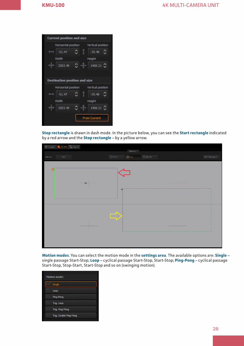
Window’s motion is possible for every rectangle. You just need to select the size and position of Start rectangle and Stop rectangle The positions and the sizes of Start and Stop windows can be defined with cursor or by indicating the positions in the settings area: Current position and size and Destination position and size.
If you want to set the final window’s position exactly in the place the start window is, you need to use the From Current button. In the picture below, you can see Start window and Stop window overlapping (in identical positions).
28
KMU-100 4K MULTI-CAMERA UNIT
Stop rectangle is drawn in dash mode. In the picture below, you can see the Start rectangle indicated by a red arrow and the Stop rectangle – by a yellow arrow.
Motion modes. You can select the motion mode in the settings area. The available options are: Single – single passage Start-Stop; Loop – cyclical passage Start-Stop, Start-Stop; Ping-Pong – cyclical passage Start-Stop, Stop-Start, Start-Stop and so on (swinging motion).

29
KMU-100 4K MULTI-CAMERA UNIT
Trig Loop, Trig Ping-Pong, Trig Double Ping-Pong – single pass: Start-Stop, Stop-Start.
Trig. motion triggered by a signal from outside the KMU-100 device. You will see the motion as a movement of the virtual camera window.
In addition to changing the window’s position, you can define change of its size – effectively realizing a zoom function (as in the picture with arrows: the Stop window has much smaller size than the Start window).
For the selected motion, you can choose from three defined speed modes: slow, medium or fast. You can also set the exact speed with the slider or customize the animation speed by clicking the up-down arrows or enter the desired value using the keyboard. See the image below
After selecting the size and position of start and stop window, motion type and its speed, you can start the motion by clicking Play motion (as in the picture above).
4. Preview on the monitors area – Multiviewer
You can choose from among the following Multiviewer preview on the monitors’ modes: Preview, Motion, Quad view.
Settings preview on the live input is possible only with the Multiviewer out There are three modes of Multiviewer outputs:
30
KMU-100 4K MULTI-CAMERA UNIT
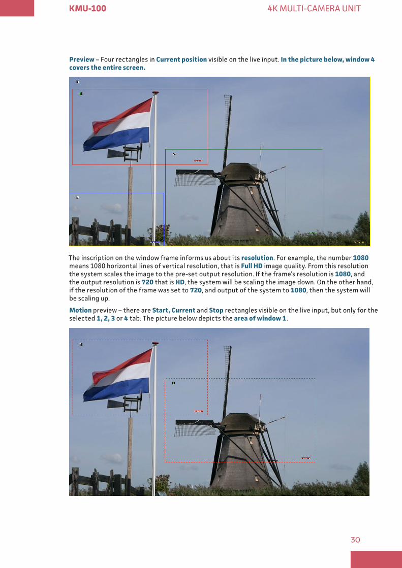
Preview – Four rectangles in Current position visible on the live input. In the picture below, window 4 covers the entire screen
The inscription on the window frame informs us about its resolution. For example, the number 1080 means 1080 horizontal lines of vertical resolution, that is Full HD image quality. From this resolution the system scales the image to the pre-set output resolution. If the frame’s resolution is 1080, and the output resolution is 720 that is HD, the system will be scaling the image down. On the other hand, if the resolution of the frame was set to 720, and output of the system to 1080, then the system will be scaling up.
Motion preview – there are Start, Current and Stop rectangles visible on the live input, but only for the selected 1, 2, 3 or 4 tab. The picture below depicts the area of window 1.
31
KMU-100 4K MULTI-CAMERA UNIT
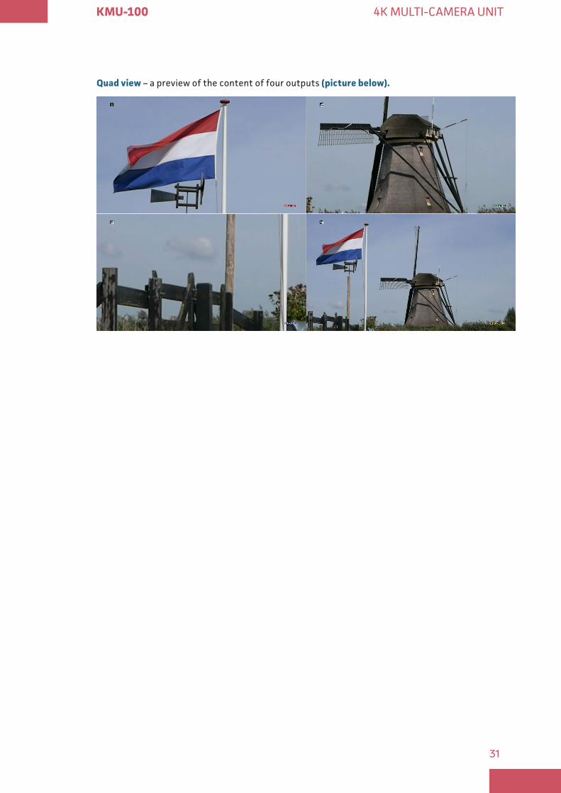
Quad view – a preview of the content of four outputs (picture below)
32
KMU-100 4K MULTI-CAMERA UNIT
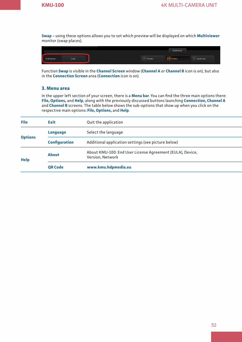
Swap – using these options allows you to set which preview will be displayed on which Multiviewer monitor (swap places).
Function Swap is visible in the Channel Screen window (Channel A or Channel B icon is on), but also in the Connection Screen area (Connection icon is on).
3 Menu areaIn the upper left section of your screen, there is a Menu bar. You can find the three main options there: File, Options, and Help, along with the previously discussed buttons launching Connection, Channel A and Channel B screens. The table below shows the sub-options that show up when you click on the respective main options: File, Options, and Help.
File Exit Quit the application
OptionsLanguage Select the language
Configuration Additional application settings (see picture below)
HelpAbout About KMU-100: End User License Agreement (EULA), Device,
Version, Network
QR Code www kmu hdpmedia eu
33
KMU-100 4K MULTI-CAMERA UNIT
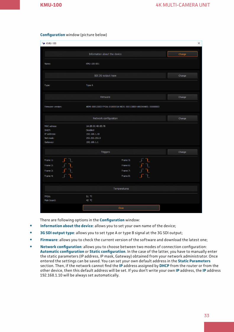
Configuration window (picture below)
There are following options in the Configuration window:
y Information about the device: allows you to set your own name of the device;
y 3G SDI output type: allows you to set type A or type B signal at the 3G SDI output;
y Firmware: allows you to check the current version of the software and download the latest one;
y Network configuration: allows you to choose between two modes of connection configuration: Automatic configuration or Static configuration. In the case of the latter, you have to manually enter the static parameters (IP address, IP mask, Gateway) obtained from your network administrator. Once entered the settings can be saved. You can set your own default address in the Static Parameters section. Then, if the network cannot find the IP address assigned by DHCP from the router or from the other device, then this default address will be set. If you don’t write your own IP address, the IP address 192.168.1.10 will be always set automatically.
34
KMU-100 4K MULTI-CAMERA UNIT
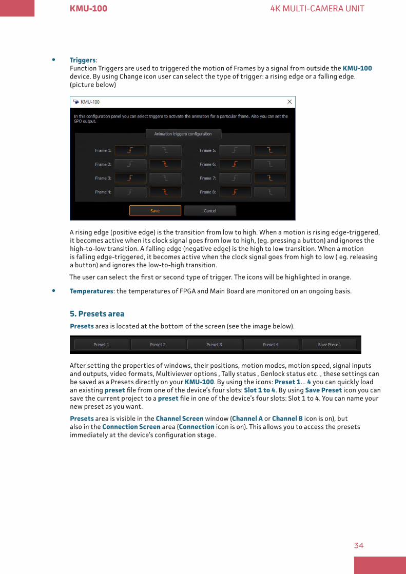
y Triggers: Function Triggers are used to triggered the motion of Frames by a signal from outside the KMU-100 device. By using Change icon user can select the type of trigger: a rising edge or a falling edge. (picture below)
A rising edge (positive edge) is the transition from low to high. When a motion is rising edge-triggered, it becomes active when its clock signal goes from low to high, (eg. pressing a button) and ignores the high-to-low transition. A falling edge (negative edge) is the high to low transition. When a motion is falling edge-triggered, it becomes active when the clock signal goes from high to low ( eg. releasing a button) and ignores the low-to-high transition.
The user can select the first or second type of trigger. The icons will be highlighted in orange.
y Temperatures: the temperatures of FPGA and Main Board are monitored on an ongoing basis.
5 Presets areaPresets area is located at the bottom of the screen (see the image below).
After setting the properties of windows, their positions, motion modes, motion speed, signal inputs and outputs, video formats, Multiviewer options , Tally status , Genlock status etc. , these settings can be saved as a Presets directly on your KMU-100. By using the icons: Preset 1... 4 you can quickly load an existing preset file from one of the device’s four slots: Slot 1 to 4. By using Save Preset icon you can save the current project to a preset file in one of the device’s four slots: Slot 1 to 4. You can name your new preset as you want.
Presets area is visible in the Channel Screen window (Channel A or Channel B icon is on), but also in the Connection Screen area (Connection icon is on). This allows you to access the presets immediately at the device’s configuration stage.
35
KMU-100 4K MULTI-CAMERA UNIT
� Hard reset
There is a small RESET hole in the rear part of the casing with a button to reset the device underneath. If you want to reset the KMU-100, you have to press this button when the device is connected to the power supply. You can do it with a tool that fits into the hole. There are three levels of reset depending on the length of time you hold the reset button:
0 5 to 3 seconds – resets only the FPGA system.
3 to 10 seconds – resets the LAN settings – restoring the default network settings – DHCP enabled, but in the case the address is not assigned automatically then IP will be 192.168.1.10, mask: 255.255.255.0, and gateway: 192.168.1.1.
Above 10 seconds – return to the factory settings: resets the network settings and all the presets to their default values, resets the LAN settings as above, sets the default name of the device: ‚KMU-100’, inputs: 4xSDI, outputs: 1080p50 at the output level type A, quarter of a screen frames, individual animations at the speed of 3, stopped, MultiViewers in Preview mode, swap turned off, MultiViewer’s SDI output turned off and genlock enabled without termination.
36
KMU-100 4K MULTI-CAMERA UNIT
Camera Control Unit RMC 185 with Joystick
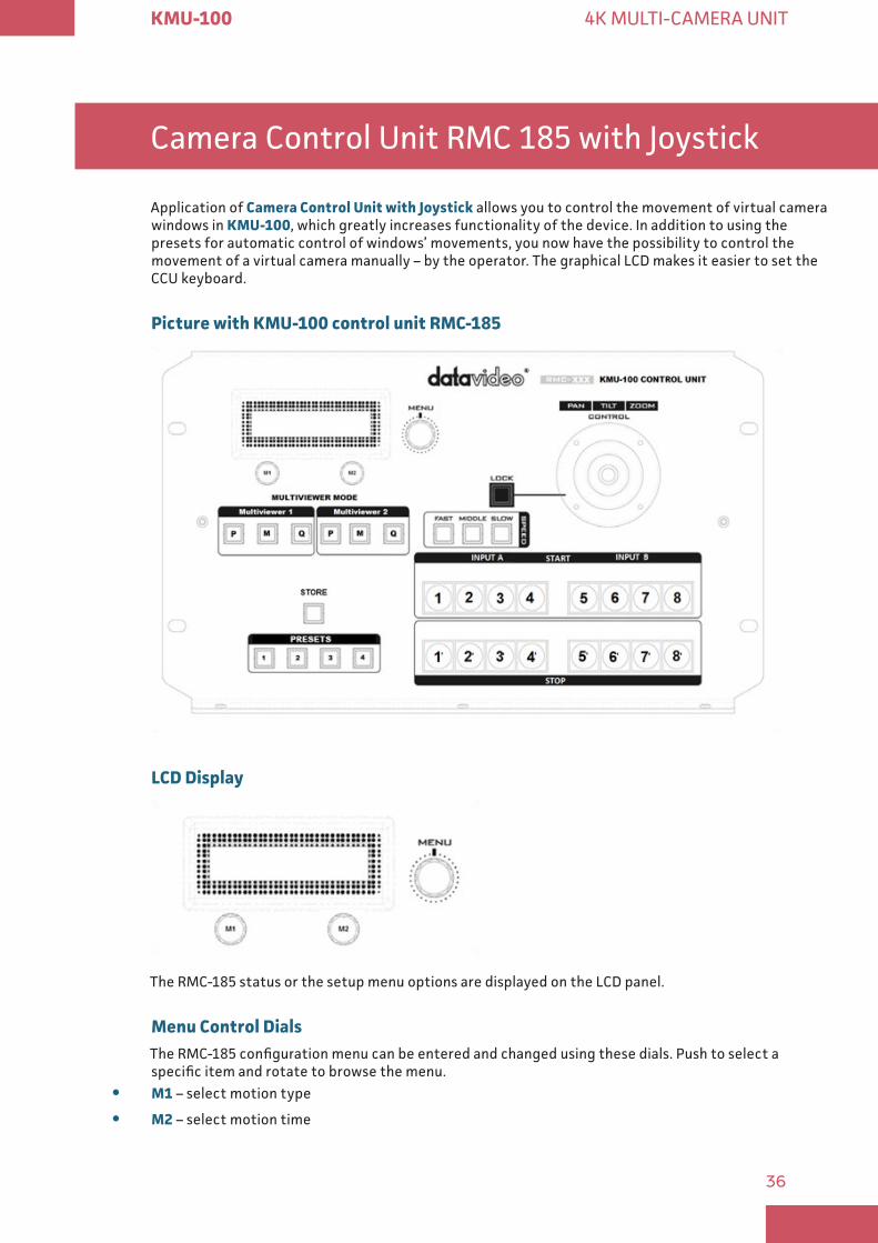
Application of Camera Control Unit with Joystick allows you to control the movement of virtual camera windows in KMU-100, which greatly increases functionality of the device. In addition to using the presets for automatic control of windows’ movements, you now have the possibility to control the movement of a virtual camera manually – by the operator. The graphical LCD makes it easier to set the CCU keyboard.
Picture with KMU-100 control unit RMC-185
LCD Display
The RMC-185 status or the setup menu options are displayed on the LCD panel.
Menu Control Dials The RMC-185 configuration menu can be entered and changed using these dials. Push to select a specific item and rotate to browse the menu.
y M1 – select motion type
y M2 – select motion time
37
KMU-100 4K MULTI-CAMERA UNIT
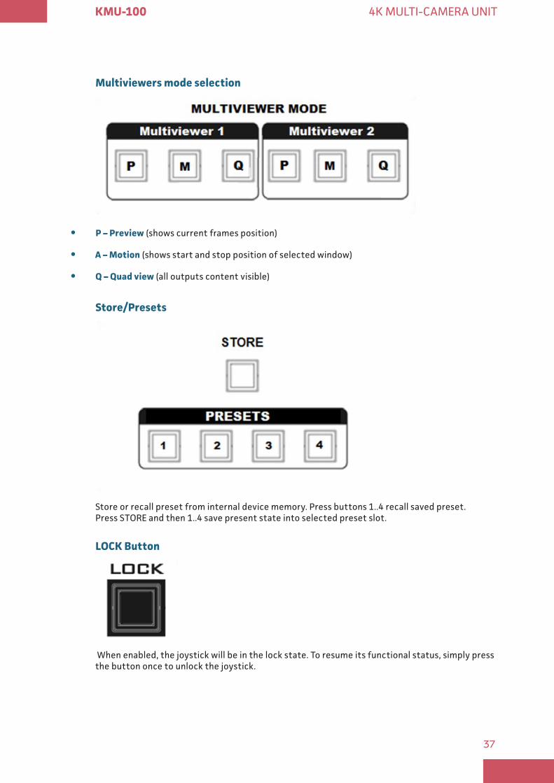
Multiviewers mode selection
y P – Preview (shows current frames position)
y A – Motion (shows start and stop position of selected window)
y Q – Quad view (all outputs content visible)
Store/Presets
Store or recall preset from internal device memory. Press buttons 1..4 recall saved preset. Press STORE and then 1..4 save present state into selected preset slot.
LOCK Button
When enabled, the joystick will be in the lock state. To resume its functional status, simply press the button once to unlock the joystick.
38
KMU-100 4K MULTI-CAMERA UNIT
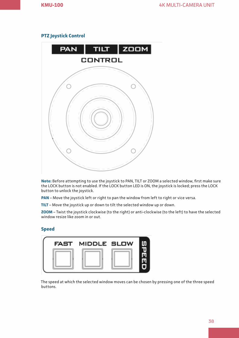
PTZ Joystick Control
Note: Before attempting to use the joystick to PAN, TILT or ZOOM a selected window, first make sure the LOCK button is not enabled. If the LOCK button LED is ON, the joystick is locked; press the LOCK button to unlock the joystick.
PAN – Move the joystick left or right to pan the window from left to right or vice versa.
TILT – Move the joystick up or down to tilt the selected window up or down.
ZOOM – Twist the joystick clockwise (to the right) or anti-clockwise (to the left) to have the selected window resize like zoom in or out.
Speed
The speed at which the selected window moves can be chosen by pressing one of the three speed buttons.
39
KMU-100 4K MULTI-CAMERA UNIT
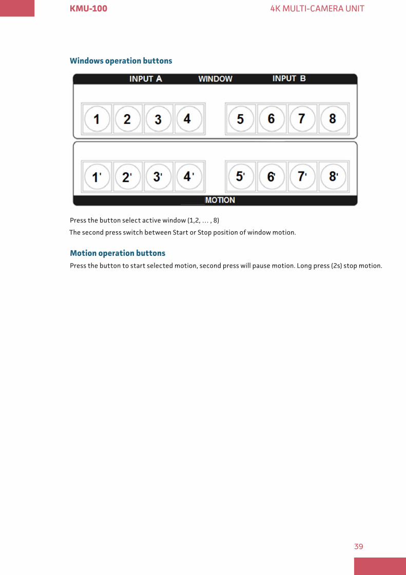
Windows operation buttons
Press the button select active window (1,2, … , 8)
The second press switch between Start or Stop position of window motion.
Motion operation buttonsPress the button to start selected motion, second press will pause motion. Long press (2s) stop motion.
40
KMU-100 4K MULTI-CAMERA UNIT
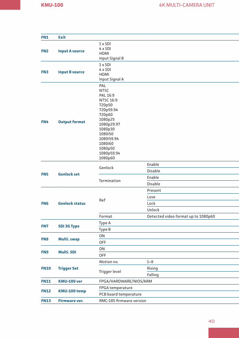
FN1 Exit
FN2 Input A source
1 x SDI 4 x SDI HDMI Input Signal B
FN3 Input B source
1 x SDI 4 x SDI HDMI Input Signal A
FN4 Output format
PAL NTSC PAL 16:9 NTSC 16:9 720p50 720p59.94 720p60 1080p25 1080p29.97 1080p30 1080i50 1080i59.94 1080i60 1080p50 1080p59.94 1080p60
FN5 Genlock set
GenlockEnable
Disable
TerminationEnable
Disable
FN6 Genlock statusRef
Present
Lose
Lock
Unlock
Format Detected video format up to 1080p60
FN7 SDI 3G TypeType A
Type B
FN8 Multi swapON
OFF
FN9 Multi SDION
OFF
FN10 Trigger Set
Motion no. 1–8
Trigger levelRising
Falling
FN11 KMU-100 ver FPGA/HARDWARE/NIOS/ARM
FN12 KMU-100 tempFPGA temperature
PCB board temperature
FN13 Firmware ver RMC-185 firmware version
41
KMU-100 4K MULTI-CAMERA UNIT
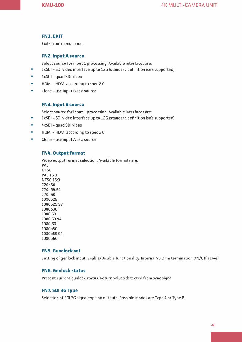
FN1 EXITExits from menu mode.
FN2 Input A source Select source for input 1 processing. Available interfaces are:
y 1xSDI – SDI video interface up to 12G (standard definition isn’s supported)
y 4xSDI – quad SDI video
y HDMI – HDMI according to spec 2.0
y Clone – use input B as a source
FN3 Input B source Select source for input 1 processing. Available interfaces are:
y 1xSDI – SDI video interface up to 12G (standard definition isn’s supported)
y 4xSDI – quad SDI video
y HDMI – HDMI according to spec 2.0
y Clone – use input A as a source
FN4 Output formatVideo output format selection. Available formats are: PAL NTSC PAL 16:9 NTSC 16:9 720p50 720p59.94 720p60 1080p25 1080p29.97 1080p30 1080i50 1080i59.94 1080i60 1080p50 1080p59.94 1080p60
FN5 Genclock setSetting of genlock input. Enable/Disable functionality. Internal 75 Ohm termination ON/Off as well.
FN6 Genlock statusPresent current gunlock status. Return values detected from sync signal
FN7 SDI 3G TypeSelection of SDI 3G signal type on outputs. Possible modes are Type A or Type B.

42
KMU-100 4K MULTI-CAMERA UNIT
FN8 Multi swapMultiviewer outputs swap. If ON content on multiviewer HDMI outputs is swapped.
FN9 Multi SDIMultiviewer out available on 4th SDI output. If ON the 4th SDI output in every channel works as multiviewer output.
FN10 EXITTrigger set. Settings of triggered motion. Triggers are controlled from external device by level. Possible to define active state as Rising or Falling.
FN11 KMU-100 verKMU-100 firmware revision.
FN12 KMU-100 tempKMU-100 FPGA and PCB board actual temperature.
FN13 Firmware ver RMC-185 firmware revision.
43
KMU-100 4K MULTI-CAMERA UNIT
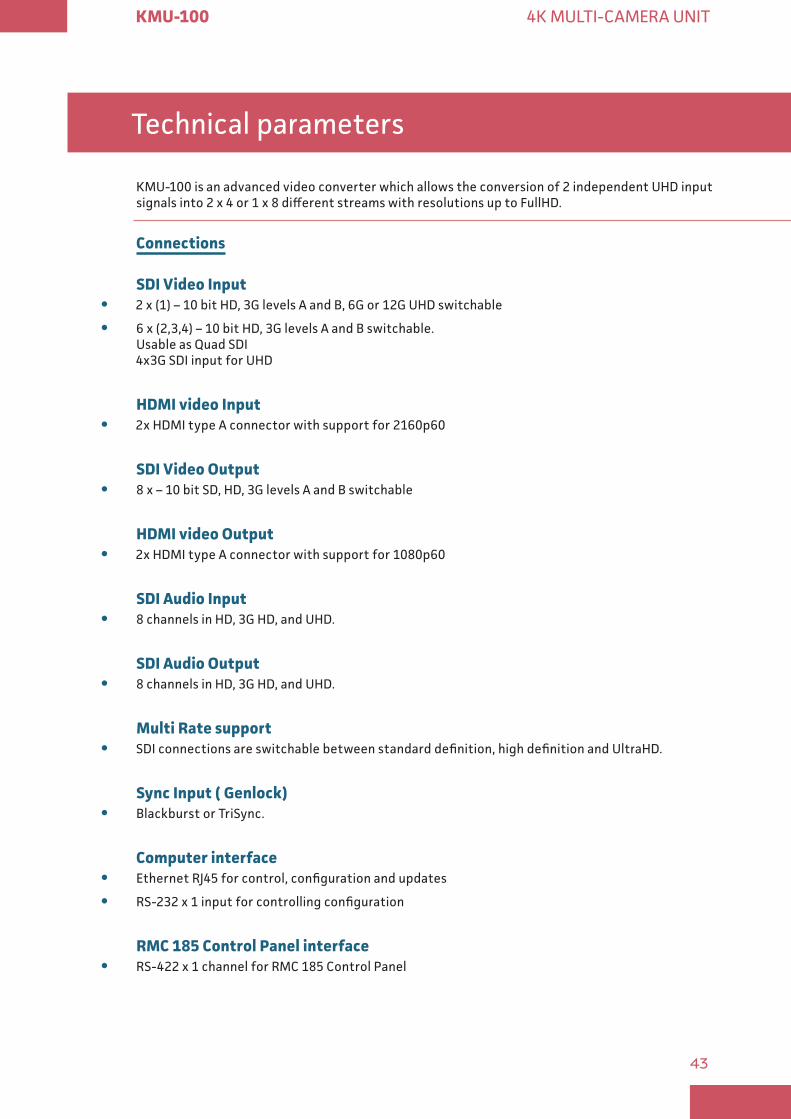
Technical parameters
KMU-100 is an advanced video converter which allows the conversion of 2 independent UHD input signals into 2 x 4 or 1 x 8 different streams with resolutions up to FullHD.
Connections
SDI Video Input y 2 x (1) – 10 bit HD, 3G levels A and B, 6G or 12G UHD switchable
y 6 x (2,3,4) – 10 bit HD, 3G levels A and B switchable. Usable as Quad SDI 4x3G SDI input for UHD
HDMI video Input y 2x HDMI type A connector with support for 2160p60
SDI Video Output y 8 x – 10 bit SD, HD, 3G levels A and B switchable
HDMI video Output y 2x HDMI type A connector with support for 1080p60
SDI Audio Input y 8 channels in HD, 3G HD, and UHD.
SDI Audio Output y 8 channels in HD, 3G HD, and UHD.
Multi Rate support y SDI connections are switchable between standard definition, high definition and UltraHD.
Sync Input ( Genlock) y Blackburst or TriSync.
Computer interface y Ethernet RJ45 for control, configuration and updates
y RS-232 x 1 input for controlling configuration
RMC 185 Control Panel interface y RS-422 x 1 channel for RMC 185 Control Panel
44
KMU-100 4K MULTI-CAMERA UNIT
GPIO interface y 8 General Purpose Inputs
Software
Software Control A dedicated software control utility application for changing settings via Windows 7, Windows 8, and Windows 10 is included free of charge.
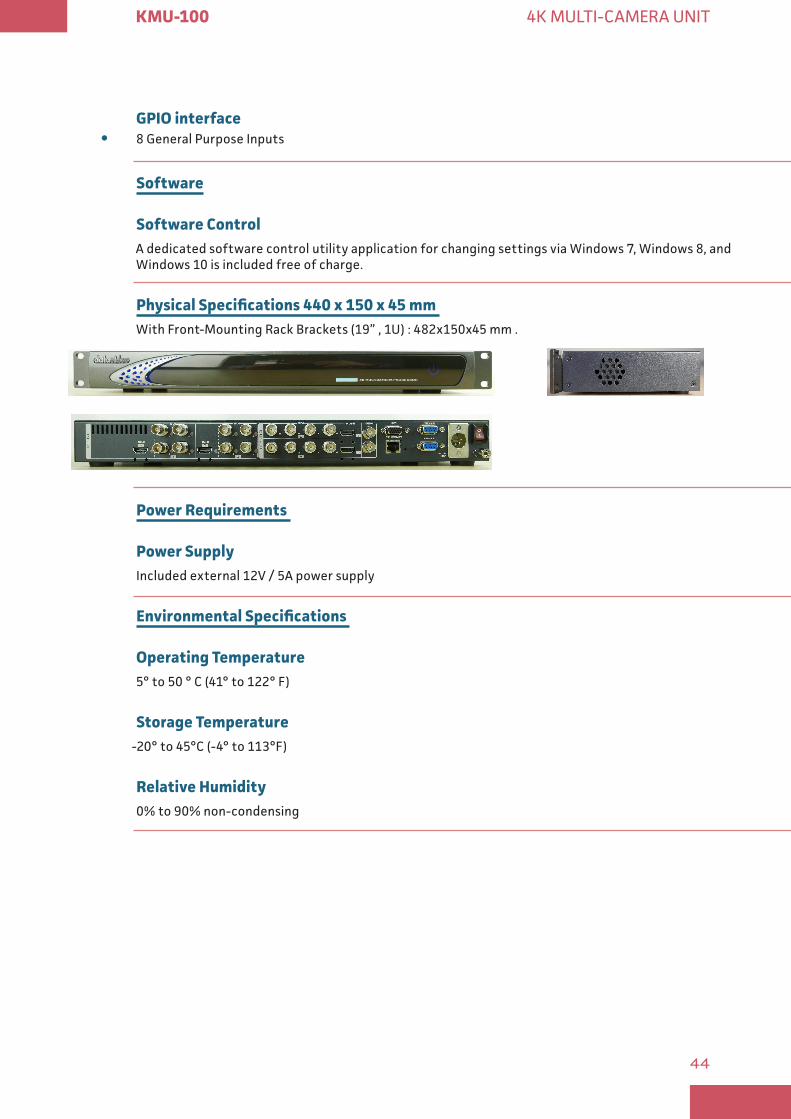
Physical Specifications 440 x 150 x 45 mm With Front-Mounting Rack Brackets (19” , 1U) : 482x150x45 mm .
Power Requirements
Power Supply Included external 12V / 5A power supply
Environmental Specifications
Operating Temperature 5° to 50 ° C (41° to 122° F)
Storage Temperature -20° to 45°C (-4° to 113°F)
Relative Humidity 0% to 90% non-condensing
45
KMU-100 4K MULTI-CAMERA UNIT
Processing
Two independent channels
Outputs definition Each channel has a definition of four rectangles indicating the way the input signal is divided into 4 different outputs. It is done by outlining 4 different windows: 1, 2, 3 and 4 (5, 6, 7 and 8). The content bordered by each window will be sent to a corresponding output.
Windows motionMotion is possible for every rectangle. User selects the size and position of Start and Stop rectangle. Motion modes available: Single-single passage Start-Stop, Loop – cyclic pass Start-Stop, Start-Stop, Ping-Pong – cyclic pass Start-Stop, Stop-Start, Start-Stop, Trig. Loop , Trig. Ping-Pong and Trig. Double Ping-Pong - single pass: Start-Stop, Stop-Start.
Trig. motion triggered by a signal from outside the KMU -100 device.
Multiviewer outputLive preview of the selected outputs:
y Preview – four rectangles in Start position on the live input,
y Motion preview – Start, Current and Stop rectangles visible on the live input, but only for the selected 1, 2, 3 or 4 tab,
y Quad view – preview of the content of four outputs,
Standards
SD Format Support625/25 PAL, 525/29.97 NTSC
1 5 Gb/s HD Format Support720p50, 720p59.94, 1080p25,1080p29.97, 1080i50, 1080i59.94.
3 Gb/s HD Format Support1080p50, 1080p59.94 and 1080p60 levels A and B
Ultra HD Format Support2160p25, 2160p29.97, 2160p50, 2160p59.94.
SDI ComplianceSMPTE 259M, SMPTE 292M, SMPTE 296M, SMPTE 425M, SMPTE2082-1
Audio Sampling Television standard sample rate of 48kHz and 24-bit HD, 20-bit SD.

46
KMU-100 4K MULTI-CAMERA UNIT
Video Sampling4:2:2
Color Precision10-bit
Color SpaceREC 601, REC 709
www kmu hdpmedia eu
47
KMU-100 4K MULTI-CAMERA UNIT
Service & Support