Advanced Vehicle Technology_Heisler_Chapter7_Final Drive Transmissions
44
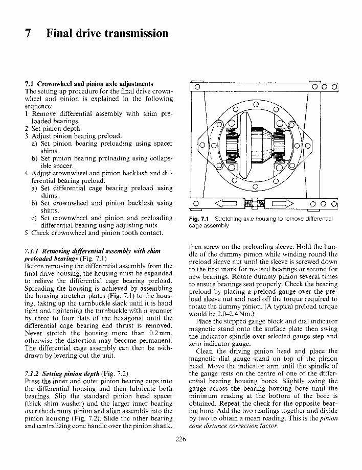
7 Final drive transmission 7.1 Crownwheel and pinion axle adjustments The setting up procedure for the final drive crown- wheel and pinion is explained in the following sequence: 1 Remove differential assembly with shim pre- loaded bearings. 2 Set pinion depth. 3 Adjust pinion bearing preload. a) Set pinion bearing preloading using spacer shims. b) Set pinion bearing preloading using collaps- ible spacer. 4 Adjust crownwheel and pinion backlash and dif- ferential bearing preload. a) Set differential cage bearing preload using shims. b) Set crownwheel and pinion backlash using shims. c) Set crownwheel and pinion and preloading differential bearing using adjusting nuts. 5 Check crownwheel and pinion tooth contact. 7.1.1 Removing differential assembly with shim preloaded bearings (Fig. 7.1) Before removing the differential assembly from the final drive housing, the housing must be expanded to relieve the differential cage bearing preload. Spreading the housing is achieved by assembling the housing stretcher plates (Fig. 7.1) to the hous- ing, taking up the turnbuckle slack until it is hand tight and tightening the turnbuckle with a spanner by three to four fiats of the hexagonal until the differential cage bearing end thrust is removed. Never stretch the housing more than 0.2mm, otherwise the distortion may become permanent. The differential cage assembly can then be with- drawn by levering out the unit. 7.1.2 Setting pinion depth (Fig. 7.2) Press the inner and outer pinion bearing cups into the differential housing and then lubricate both bearings. Slip the standard pinion head spacer (thick shim washer) and the larger inner bearing over the dummy pinion and align assembly into the pinion housing (Fig. 7.2). Slide the other bearing and centralizing cone handle over the pinion shank, 226 1,' i 0 q l ooo t • Fig. 7.1 Stretching axle housing to remove differential cage assembly then screw on the preloading sleeve. Hold the han- dle of the dummy pinion while winding round the preload sleeve nut until the sleeve is screwed down to the first mark for re-used bearings or second for new bearings. Rotate dummy pinion several times to ensure bearings seat properly. Check the bearing preload by placing a preload gauge over the pre- load sleeve nut and read off the torque required to rotate the dummy pinion. (A typical preload torque would be 2.0-2.4 Nm.) Place the stepped gauge block and dial indicator magnetic stand onto the surface plate then swing the indicator spindle over selected gauge step and zero indicator gauge. Clean the driving pinion head and place the magnetic dial gauge stand on top of the pinion head. Move the indicator arm until the spindle of the gauge rests on the centre of one of the differ- ential bearing housing bores. Slightly swing the gauge across the bearing housing bore until the minimum reading at the bottom of the bore is obtained. Repeat the check for the opposite bear- ing bore. Add the two readings together and divide by two to obtain a mean reading. This is the pinion cone distance correction factor.
Transcript of Advanced Vehicle Technology_Heisler_Chapter7_Final Drive Transmissions
7 Final drive transmission
7.1 Crownwheel and pinion axle adjustments The setting up procedure for the final drive crown- wheel and pinion is explained in the following sequence: 1 Remove differential assembly with shim pre-
loaded bearings. 2 Set pinion depth. 3 Adjust pinion bearing preload.
a) Set pinion bearing preloading using spacer shims.
b) Set pinion bearing preloading using collaps- ible spacer.
4 Adjust crownwheel and pinion backlash and dif- ferential bearing preload. a) Set differential cage bearing preload using
shims. b) Set crownwheel and pinion backlash using
shims. c) Set crownwheel and pinion and preloading
differential bearing using adjusting nuts. 5 Check crownwheel and pinion tooth contact.
7.1.1 Removing differential assembly with shim preloaded bearings (Fig. 7.1) Before removing the differential assembly from the final drive housing, the housing must be expanded to relieve the differential cage bearing preload. Spreading the housing is achieved by assembling the housing stretcher plates (Fig. 7.1) to the hous- ing, taking up the turnbuckle slack until it is hand tight and tightening the turnbuckle with a spanner by three to four fiats of the hexagonal until the differential cage bearing end thrust is removed. Never stretch the housing more than 0.2mm, otherwise the distortion may become permanent. The differential cage assembly can then be with- drawn by levering out the unit.
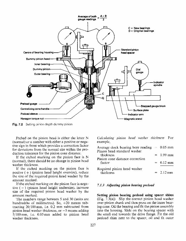
7.1.2 Setting pinion depth (Fig. 7.2) Press the inner and outer pinion bearing cups into the differential housing and then lubricate both bearings. Slip the standard pinion head spacer (thick shim washer) and the larger inner bearing over the dummy pinion and align assembly into the pinion housing (Fig. 7.2). Slide the other bearing and centralizing cone handle over the pinion shank,
226
1, ' i
0 q l
ooo t •
Fig. 7.1 Stretching axle housing to remove differential cage assembly
then screw on the preloading sleeve. Hold the han- dle of the dummy pinion while winding round the preload sleeve nut until the sleeve is screwed down to the first mark for re-used bearings or second for new bearings. Rotate dummy pinion several times to ensure bearings seat properly. Check the bearing preload by placing a preload gauge over the pre- load sleeve nut and read off the torque required to rotate the dummy pinion. (A typical preload torque would be 2.0-2.4 Nm.)
Place the stepped gauge block and dial indicator magnetic stand onto the surface plate then swing the indicator spindle over selected gauge step and zero indicator gauge.
Clean the driving pinion head and place the magnetic dial gauge stand on top of the pinion head. Move the indicator arm until the spindle of the gauge rests on the centre of one of the differ- ential bearing housing bores. Slightly swing the gauge across the bearing housing bore until the minimum reading at the bottom of the bore is obtained. Repeat the check for the opposite bear- ing bore. Add the two readings together and divide by two to obtain a mean reading. This is the pinion cone distance correction factor.
Average of both ~_ _..._.- gauge readings
A + B m
2
/ / C = New bearings D = Original bearings
Centre of bearing h o u s i n g . ~ -
Dummy pinion head
Inner b e a r i n g ~
Dummy pinion--------~
Outer bearing
Preload guage - ~
Centralizing cone handle
Preload sleeve
Hexagon torque nut /
Fig. 7.2 Setting pinion depth dummy pinion
Standard pinion head spacer
Indicator spindle
C
d gauge block
Indicator arm
Magnetic stand
Etched on the pinion head is either the letter N (normal) or a number with either a positive or nega- tive sign in front which provides a correction factor for deviations from the normal size within the pro- duction tolerance for the pinion cone distance.
If the etched marking on the pinion face is N (normal), there should be no change in pinion head washer thickness.
If the etched marking on the pinion face is positve ( + ) (pinion head height oversize), reduce the size of the required pinion head washer by the amount marked.
If the etched marking on the pinion face is nega- tive ( - ) (pinion head height undersize), increase size of the required pinion head washer by the amount marked.
The numbers range between 5 and 30 (units are hundredths of millimetres). So, +20 means sub- tracting 20/100mm, i.e. 0.2 mm subtracted from pinion head washer thickness, or - 5 means adding 5/100mm, i.e. 0.05mm added to pinion head washer thickness.
227
Calculating pinion head washer thickness For example,
Average clock bearing bore reading = 0.05 mm Pinion head standard washer
thickness = 1.99 mm Pinion cone distance correction
factor = 0.12 mm
Required pinion head washer thickness = 2.12 mm
7.1.3 Adjusting pinion bearing preload
Setting pinion bearing preload using spacer shims (Fig. 7.3(a)) Slip the correct pinion head washer over pinion shank and then press on the inner bear- ing cone. Oil the bearing and fit the pinion assembly into the housing. Slide on the bearing spacer with the small end towards the drive flange. Fit the old preload shim next to the spacer, oil and fit outer
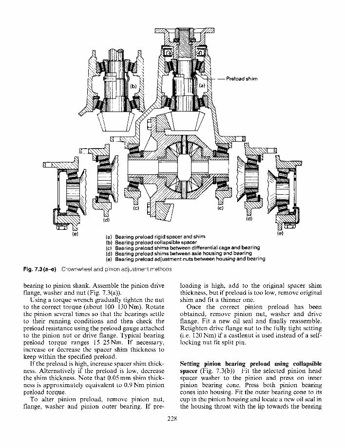
Preload shim
(c) W/~\\\'~' / (c)
(d) ~ (d)
(e) (a) Bearing preload rigid spacer and shim (b) Bearing preload collapsible spacer (c) Bearing preload shims between differential cage and bearing (d) Bearing preload shims between axle housing and bearing (e) Bearing preload adjustment nuts between housing and bearing
Fig. 7.3(a-e) Crownwheel and pinion adjustment methods
(e)
beating to pinion shank. Assemble the pinion drive flange, washer and nut (Fig. 7.3(a)).
Using a torque wrench gradually tighten the nut to the correct torque (about 100-130 Nm). Rotate the pinion several times so that the bearings settle to their running conditions and then check the preload resistance using the preload gauge attached to the pinion nut or drive flange. Typical bearing preload torque ranges 15-25Nm. If necessary, increase or decrease the spacer shim thickness to keep within the specified preload.
If the preload is high, increase spacer shim thick- ness. Alternatively if the preload is low, decrease the shim thickness. Note that 0.05 mm shim thick- ness is approximately equivalent to 0.9 Nm pinion preload torque.
To alter pinion preload, remove pinion nut, flange, washer and pinion outer bearing. If pre-
loading is high, add to the original spacer shim thickness, but if preload is too low, remove original shim and fit a thinner one.
Once the correct pinion preload has been obtained, remove pinion nut, washer and drive flange. Fit a new oil seal and finally reassemble. Retighten drive flange nut to the fully tight setting (i.e. 120 Nm) if a castlenut is used instead of a self- locking nut fit split pin.
Setting pinion bearing preload using collapsible spacer (Fig. 7.3(b)) Fit the selected pinion head spacer washer to the pinion and press on inner pinion bearing cone. Press both pinion bearing cones into housing. Fit the outer bearing cone to its cup in the pinion housing and locate a new oil seal in the housing throat with the lip towards the bearing
228
and press it in until it contacts the inner shoulder. Lightly oil the seal.
Install the pinion into the final drive housing with a new collapsible spacer (Fig. 7.3(b)). Fit the drive flange and a new retainer nut. Tighten the nut until a slight end float can be felt on the pinion.
Attach the pinion preload gauge to the drive flange and measure the oil seal drag (usually around 0.6Nm). To this oil sealed preload drag add the bearing preload torque of 2.2.-3.0 Nm.
i.e. Total p r e l o a d - Oil seal drag+ Bearing drag
= 0.6 + 2.5 - 3.1 Nm
Gradually and carefully tighten the drive flange nut, twisting the pinion to seat the bearings, until the required preload is obtained. Frequent checks must be taken with the preload gauge and if the maximum preload is exceeded the collapsible spacer must be renewed. Note that slackening off the drive flange nut will only remove the estab- lished excessive preload and will not reset the required preload.
7.1.4 Adjust crownwheel and pinion backlash and differential bearing preload
Setting differential cage bearing preload using shims (Figs 7.3(c and d) and 7.4) Differential bearing preload shims may be situated between the differ-
ential cage and bearings (Fig. 7.3(c)) or between axle housing and bearings (Fig. 7.3(d)). The method of setting the differential bearing preload is similar in both arrangements, but only the case of shims between the axle housing and bearing will be described.
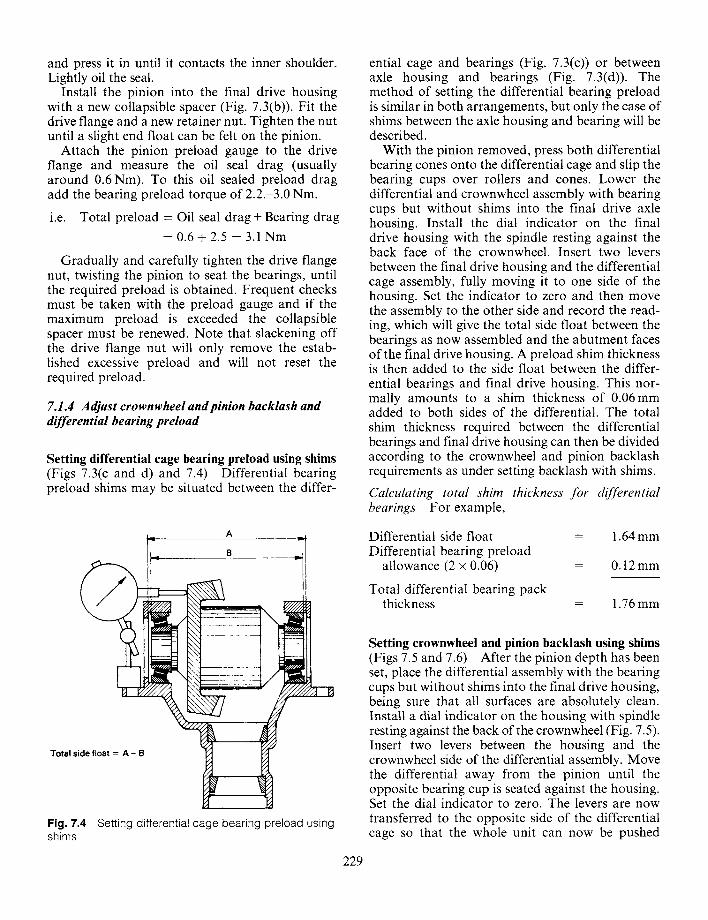
With the pinion removed, press both differential bearing cones onto the differential cage and slip the bearing cups over rollers and cones. Lower the differential and crownwheel assembly with bearing cups but without shims into the final drive axle housing. Install the dial indicator on the final drive housing with the spindle resting against the back face of the crownwheel. Insert two levers between the final drive housing and the differential cage assembly, fully moving it to one side of the housing. Set the indicator to zero and then move the assembly to the other side and record the read- ing, which will give the total side float between the bearings as now assembled and the abutment faces of the final drive housing. A preload shim thickness is then added to the side float between the differ- ential bearings and final drive housing. This nor- mally amounts to a shim thickness of 0.06mm added to both sides of the differential. The total shim thickness required between the differential bearings and final drive housing can then be divided according to the crownwheel and pinion backlash requirements as under setting backlash with shims.
Calculating total shim thickness for differential bearings For example,
i Total side float = A - B
8
,x': m
I
Fig. 7.4 Setting differential cage bearing preload using shims
Differential side float = Differential bearing preload
allowance (2 x 0.06) =
Total differential bearing pack thickness
1.64 mm
0.12mm
1.76mm
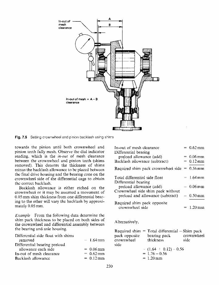
Setting crownwheel and pinion backlash using shims (Figs 7.5 and 7.6) After the pinion depth has been set, place the differential assembly with the bearing cups but without shims into the final drive housing, being sure that all surfaces are absolutely clean. Install a dial indicator on the housing with spindle resting against the back of the crownwheel (Fig. 7.5). Insert two levers between the housing and the crownwheel side of the differential assembly. Move the differential away from the pinion until the opposite bearing cup is seated against the housing. Set the dial indicator to zero. The levers are now transferred to the opposite side of the differential cage so that the whole unit can now be pushed
229
In-out of mesh clearance
A
B =i I
In-out of mesh = A - B clearance
Fig. 7.5 Setting crownwheel and pinion backlash using shims
towards the pinion until both crownwheel and pinion teeth fully mesh. Observe the dial indicator reading, which is the in-out of mesh clearance between the crownwheel and pinion teeth (shims removed). This denotes the thickness of shims minus the backlash allowance to be placed between the final drive housing and the bearing cone on the crownwheel side of the differential cage to obtain the correct backlash.
Backlash allowance is either etched on the crownwheel or it may be assumed a movement of 0.05 mm shim thickness from one differential bear- ing to the other will vary the backlash by approxi- mately 0.05 mm.
Example From the following data determine the shim pack thickness to be placed on both sides of the crownwheel and differential assembly between the bearing and axle housing.
Differential side float with shims removed
Differential bearing preload allowance each side
In-out of mesh clearance Backlash allowance
= 1.64 mm
= 0.06 mm = 0.62 mm = 0.12mm
230
In-out of mesh clearance Differential bearing
preload allowance (add) Backlash allowance (subtract)
= 0.62 mm
= 0.06 mm = 0.12 mm
Required shim pack crownwheel side = 0 .56mm
Total differential side float Differential bearing
preload allowance (add) Crownwheel side shim pack without
preload and allowance (subtract)
Required shim pack opposite crownwheel side
= 1.64 mm
= 0.06 mm
= 0.50 mm
= 1.20mm
Alternatively,
Required shim = Total d i f fe ren t ia l - Shim pack pack opposite bearing pack crownwheel crownwheel thickness side side
= (1.64 + 0 .12 ) -0 .56 = 1 .76 -0 .56 = 1.20 mm
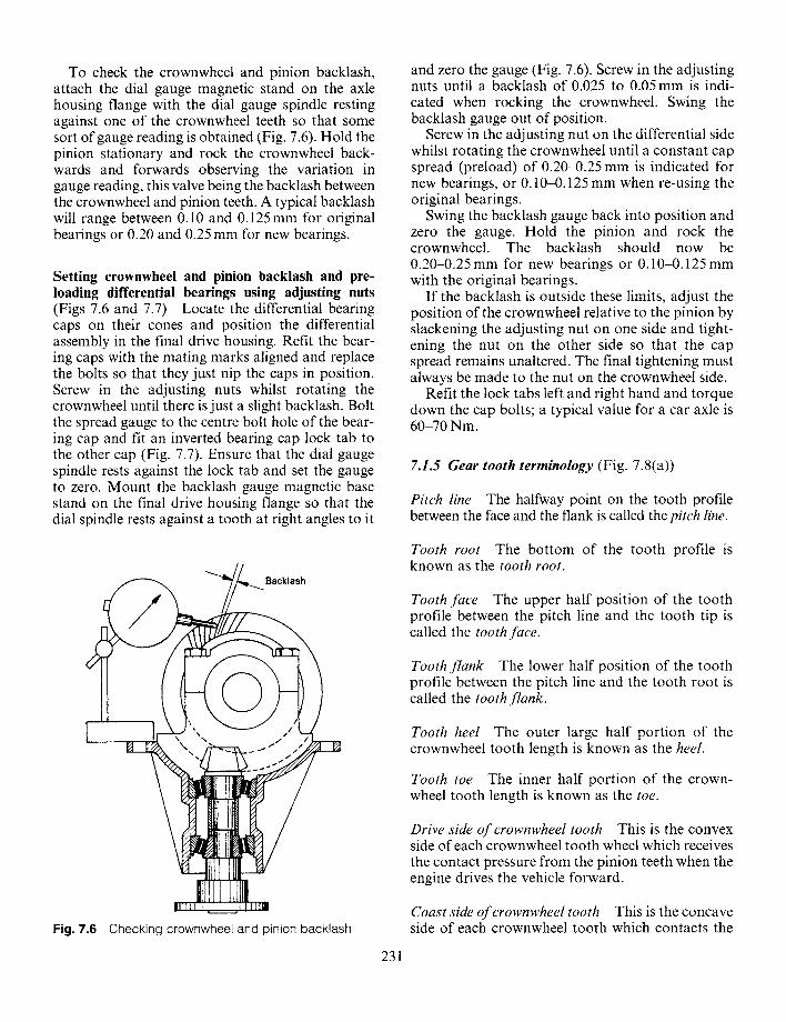
To check the crownwheel and pinion backlash, attach the dial gauge magnetic stand on the axle housing flange with the dial gauge spindle resting against one of the crownwheel teeth so that some sort of gauge reading is obtained (Fig. 7.6). Hold the pinion stationary and rock the crownwheel back- wards and forwards observing the variation in gauge reading, this valve being the backlash between the crownwheel and pinion teeth. A typical backlash will range between 0.10 and 0.125 mm for original bearings or 0.20 and 0.25 mm for new bearings.
Setting crownwheel and pinion backlash and pre- loading differential bearings using adjusting nuts (Figs 7.6 and 7.7) Locate the differential bearing caps on their cones and position the differential assembly in the final drive housing. Refit the bear- ing caps with the mating marks aligned and replace the bolts so that they just nip the caps in position. Screw in the adjusting nuts whilst rotating the crownwheel until there is just a slight backlash. Bolt the spread gauge to the centre bolt hole of the bear- ing cap and fit an inverted bearing cap lock tab to the other cap (Fig. 7.7). Ensure that the dial gauge spindle rests against the lock tab and set the gauge to zero. Mount the backlash gauge magnetic base stand on the final drive housing flange so that the dial spindle rests against a tooth at right angles to it
and zero the gauge (Fig. 7.6). Screw in the adjusting nuts until a backlash of 0.025 to 0.05 mm is indi- cated when rocking the crownwheel. Swing the backlash gauge out of position.
Screw in the adjusting nut on the differential side whilst rotating the crownwheel until a constant cap spread (preload) of 0.20-0.25 mm is indicated for new bearings, or 0.10-0.125 mm when re-using the original bearings.
Swing the backlash gauge back into position and zero the gauge. Hold the pinion and rock the crownwheel. The backlash should now be 0.20-0.25 mm for new bearings or 0.10-0.125 mm with the original bearings.
If the backlash is outside these limits, adjust the position of the crownwheel relative to the pinion by slackening the adjusting nut on one side and tight- ening the nut on the other side so that the cap spread remains unaltered. The final tightening must always be made to the nut on the crownwheel side.
Refit the lock tabs left and right hand and torque down the cap bolts; a typical value for a car axle is 60-70 Nm.
7.1.5 Gear tooth terminology (Fig. 7.8(a))
Pitch line The halfway point on the tooth profile between the face and the flank is called the pitch line.
Backlash
Fig. 7.6 Checking crownwheel and pinion backlash
Tooth root The bottom of the tooth profile is known as the tooth root.
Tooth face The upper half position of the tooth profile between the pitch line and the tooth tip is called the tooth face.
Tooth flank The lower half position of the tooth profile between the pitch line and the tooth root is called the tooth flank.
Tooth heel The outer large half portion of the crownwheel tooth length is known as the heel.
Tooth toe The inner half portion of the crown- wheel tooth length is known as the toe.
Drive side of crownwheel tooth This is the convex side of each crownwheel tooth wheel which receives the contact pressure from the pinion teeth when the engine drives the vehicle forward.
Coast side of crownwheel tooth This is the concave side of each crownwheel tooth which contacts the
231
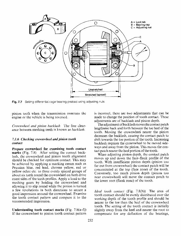
© A = Locktab B = Bearing cap C = Adjusting nut
L m Unstretched
Stretched (spread)
Fig. 7.7 Setting differential cage bearing preload using adjusting nuts
I
pinion teeth when the transmission overruns the engine or the vehicle is being reversed.
Crownwheel and pinion backlash The free clear- ance between meshing teeth is known as backlash.
7.1.6 Checking crownwheel and pinion tooth contact
Prepare crownwheel for examining tooth contact marks (Fig. 7.8) After setting the correct back- lash, the crownwheel and pinion tooth alignment should be checked for optimum contact. This may be achieved by applying a marking cream such as Prussian blue, red lead, chrome yellow, red or yellow ochre etc. to three evenly spaced groups of about six teeth round the crownwheel on both drive coast sides of the teeth profiles. Apply a load to the meshing gears by holding the crownwheel and allowing it to slip round while the pinion is turned a few revolutions in both directions to secure a good impression around the crownwheel. Examine the tooth contact pattern and compare it to the recommended impression.
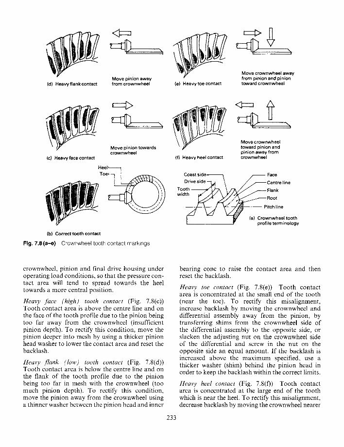
Understanding tooth contact marks (Fig. 7.8(a-f)) If the crownwheel to pinion tooth contact pattern
232
is incorrect, there are two adjustments that can be made to change the position of tooth contact. These adjustments are of backlash and pinion depth.
The adjustment of backlash moves the contact patch lengthwise back and forth between the toe heel of the tooth. Moving the crownwheel nearer the pinion decreases the backlash, causing the contact patch to shift towards the toe portion of the tooth. Increasing backlash requires the crownwheel to be moved side- ways and away from the pinion. This moves the con- tact patch nearer the heel portion of the tooth.
When adjusting pinion depth, the contact patch moves up and down the face-flank profile of the tooth. With insufficient pinion depth (pinion too far out from crownwheel) the contact patch will be concentrated at the top (face zone) of the tooth. Conversely, too much pinion depth (pinion too near crownwheel) will move the contact patch to the lower root (flank zone) of the tooth.
Ideal tooth contact (Fig. 7.8(b)) The area of tooth contact should be evenly distributed over the working depth of the tooth profile and should be nearer to the toe than the heel of the crownwheel tooth. The setting of the tooth contact is initially slightly away from the heel and nearer the root to compensate for any deflection of the bearings,
7 (d) Heavy flank contact
<3=z
!
Move pinion away from crownwheel (e) H e a v y toe contact
i . , ,
Move crownwheel away from pinion and pinion toward crownwheel
(c) Heavy face contact
M o v e crownwheel Move pinion towards toward pinion and crownwheel pinion away from
(f) Heavy heel contact crownwheel
Heel~----- zoeq Coast side ~- - Face
Drive side Cen t re l ine
Tooth ~ 1 ) - , , \ "-= / J F lank
Root
Pitch l ine
wid profile terminology (a) Crownwheel tooth
(b) Correct tooth contact
Fig. 7.8(a-e) Crownwheel tooth contact markings
crownwheel, pinion and final drive housing under operating load conditions, so that the pressure con- tact area will tend to spread towards the heel towards a more central position.
Heavy face (high) tooth contact (Fig. 7.8(c)) Tooth contact area is above the centre line and on the face of the tooth profile due to the pinion being too far away from the crownwheel (insufficient pinion depth). To rectify this condition, move the pinion deeper into mesh by using a thicker pinion head washer to lower the contact area and reset the backlash.
Heavy flank (low) tooth contact (Fig. 7.8(d)) Tooth contact area is below the centre line and on the flank of the tooth profile due to the pinion being too far in mesh with the crownwheel (too much pinion depth). To rectify this condition, move the pinion away from the crownwheel using a thinner washer between the pinion head and inner
233
bearing cone to raise the contact area and then reset the backlash.
Heavy toe contact (Fig. 7.8(e)) Tooth contact area is concentrated at the small end of the tooth (near the toe). To rectify this misalignment, increase backlash by moving the crownwheel and differential assembly away from the pinion, by transferring shims from the crownwheel side of the differential assembly to the opposite side, or slacken the adjusting nut on the crownwheel side of the differential and screw in the nut on the opposite side an equal amount. If the backlash is increased above the maximum specified, use a thicker washer (shim) behind the pinion head in order to keep the backlash within the correct limits.
Heavy heel contact (Fig. 7.8(f)) Tooth contact area is concentrated at the large end of the tooth which is near the heel. To rectify this misalignment, decrease backlash by moving the crownwheel nearer
the pinion (add shims to the crownwheel side of the differential and remove an equal thickness of shims from the opposite side) or slacken the differential side adjusting nut and tighten the crownwheel side nut an equal amount. If the backlash is reduced below the minimum specified, use a thinner washer (shim) behind the pinion head.
7.1.7 Final drive axle noise and defects Noise is produced with all types of meshing gear teeth such as from spur, straight or helical gears and even more so with bevel gears where the output is redirected at right angles to the input drive.
Vehicle noises coming from tyres, transmission, propellor shafts, universal joints and front or rear wheel bearings are often mistaken for axle noise, especially tyre to road surface rumbles which can sound very similar to abnormal axle noise. Listen- ing for the noise at varying speeds and road surfaces, on drive and overrun conditions will assist in locating the source of any abnormal sound.
Once all other causes of noise have been elimin- ated, axle noise may be suspected. The source of axle noise can be divided into gear teeth noises and bearing noise.
Gear noise Gear noise may be divided into two kinds:
1 Broken, bent or forcibly damaged gear teeth which produce an abnormal audible sound which is easily recognised over the whole speed range. a) Broken or damaged teeth may be due to
abnormally high shock loading causing sud- den tooth failure.
b) Extended overloading of both crownwheel and pinion teeth can be responsible for even- tual fatigue failure.
c) Gear teeth scoring may eventually lead to tooth profile damage. The causes of surface scoring can be due to the following:
i) Insufficient lubrication or incorrect grade of oil
ii) Insufficient care whilst running in a new final drive
iii) Insufficient crownwheel and pinion back- lash
iv) Distorted differential housing v) Crownwheel and pinion misalignment
vi) Loose pinion nut removing the pinion bearing preload.
2 Incorrect meshing of crownwheel and pinion teeth. Abnormal noises produced by poorly
234
meshed teeth generate a very pronounced cyclic pitch whine in the speed range at which it occurs whilst the vehicle is operating on either drive or overrun conditions.
Noise on drive If a harsh cyclic pitch noise is heard when the engine is driving the transmission it indicates that the pinion needs to be moved slightly out of mesh.
Noise on overrun If a pronounced humming noise is heard when the vehicle's transmission overruns the engine, this indicates that the pinion needs to be moved further into mesh.
Slackness & the drive A pronounced time lag in taking the drive up accompanied by a knock when either accelerating or decelerating may be traced to end play in the pinion assembly due possibly to defective bearings or incorrectly set up bearing spacer and shim pack.
Bearing noise Bearings which are defective pro- duce a rough growling sound that is approximately constant in volume over a narrow speed range. Driving the vehicle on a smooth road and listening for rough transmission sounds is the best method of identifying bearing failure.
A distinction between defective pinion bearings or differential cage bearings can be made by listen- ing for any constant rough sound. A fast frequency growl indicates a failed pinion bearing, while a much slower repetition growl points to a defective differential bearing. The difference in sound is because the pinion revolves at about four times the speed of the differential assembly.
To distinguish between differential bearing and half shaft bearing defects, drive the vehicle on a smooth road and turn the steering sharply right and left. If the half shaft bearings are at fault, the increased axle load imposed on the bearing will cause a rise in the noise level, conversely if there is no change in the abnormal rough sound the differ- ential bearings should be suspect.
Defective differential planet and sun gears The sun and planet gears of the differential unit very rarely develop faults. When differential failure does occur, it is usually caused by shock loading, extended overloading and seizure of the differential planet gears to the cross-shaft resulting from exces- sive wheel spin and consequently lubrication breakdown.
A roughness in the final drive transmission when the vehicle is cornering may indicate defective planet/sun gears.
7.2 Differential locks A differential lock is desirable, and in some cases essential, if the vehicle is going to operate on low traction surfaces such as sand, mud, wet or water- logged ground, worn slippery roads, ice bound roads etc. at relatively low speeds.
Drive axle differential locks are incorporated on heavy duty on/off highway and cross-country vehi- cles to provide a positive drive between axle half shafts when poor tyre to ground traction on one wheel would produce wheel spin through differen- tial bevel gear action.
The differential lock has to be engaged manually by cable or compressed air, whereas the limited slip or viscous coupling differential automatically operates as conditions demand.
All differential locks are designed to lock together two or more parts of the differential gear cluster by engaging adjacent sets of dog clutch teeth. By this method, all available power trans- mitted to the final drive will be supplied to the wheels. Even if one wheel loses grip, the opposite wheel will still receive power enabling it to produce torque and therefore tractive effect up to the limit of the tyres' ability to grip the road. Axle wind-up will be dissipated by wheel bounce, slippage or scuffing.
These unwanted reactions will occur when travelling over slippery soft or rough ground where true rolling will be difficult. Since the tyre tread cannot exactly follow the contour of the surface it is rolling over, for very brief periodic intervals there will be very little tyre to ground adhesion. As a result, any build up of torsional strain between the half shafts will be continuously released.
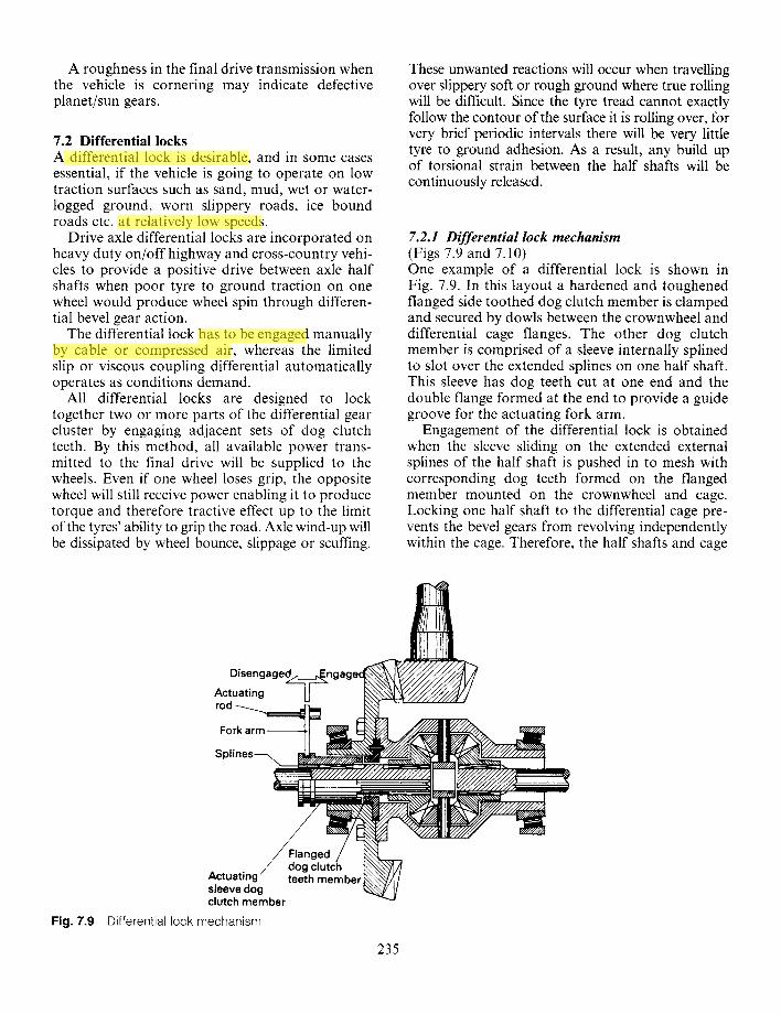
7.2.1 Differential lock mechanism (Figs 7.9 and 7.10) One example of a differential lock is shown in Fig. 7.9. In this layout a hardened and toughened flanged side toothed dog clutch member is clamped and secured by dowls between the crownwheel and differential cage flanges. The other dog clutch member is comprised of a sleeve internally splined to slot over the extended splines on one half shaft. This sleeve has dog teeth cut at one end and the double flange formed at the end to provide a guide groove for the actuating fork arm.
Engagement of the differential lock is obtained when the sleeve sliding on the extended external splines of the half shaft is pushed in to mesh with corresponding dog teeth formed on the flanged member mounted on the crownwheel and cage. Locking one half shaft to the differential cage pre- vents the bevel gears from revolving independently within the cage. Therefore, the half shafts and cage
Disengaged~_
Actuating rod ~ . . . . . ~
Fork arm
S~lines---..
Fig. 7.9
Actuating" sleeve dog clutch member
Differential lock mechanism
Flanged / dog clutch teeth member
235
zhe huang
Highlight
zhe huang
Highlight
zhe huang
Highlight
zhe huang
Highlight
Air inlet pipe
Cylinder
Piston
Retu rn spring
Dog teeth engaged
Half shaft
Hydraulic annulus seal
Support Sliding sleeve dog clutch
member
Dog teeth disengaged
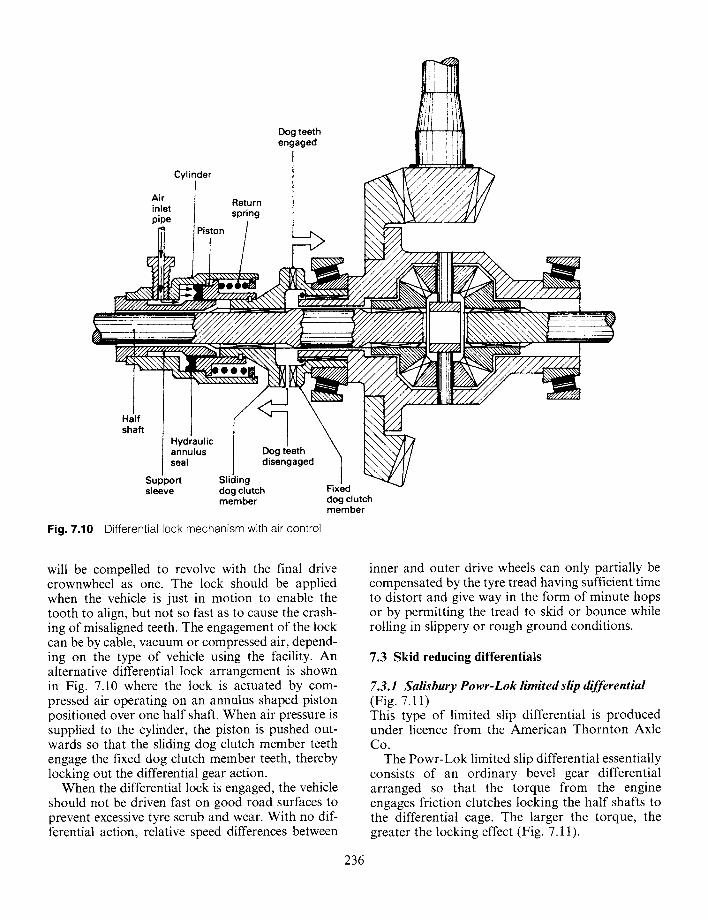
Fig. 7.10 Differential lock mechanism with air control
Fixed dog clutch member
will be compelled to revolve with the final drive crownwheel as one. The lock should be applied when the vehicle is just in motion to enable the tooth to align, but not so fast as to cause the crash- ing of misaligned teeth. The engagement of the lock can be by cable, vacuum or compressed air, depend- ing on the type of vehicle using the facility. An alternative differential lock arrangement is shown in Fig. 7.10 where the lock is actuated by com- pressed air operating on an annulus shaped piston positioned over one half shaft. When air pressure is supplied to the cylinder, the piston is pushed out- wards so that the sliding dog clutch member teeth engage the fixed dog clutch member teeth, thereby locking out the differential gear action.
When the differential lock is engaged, the vehicle should not be driven fast on good road surfaces to prevent excessive tyre scrub and wear. With no dif- ferential action, relative speed differences between
236
inner and outer drive wheels can only partially be compensated by the tyre tread having sufficient time to distort and give way in the form of minute hops or by permitting the tread to skid or bounce while rolling in slippery or rough ground conditions.
7.3 Skid reducing differentials
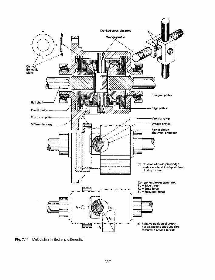
7.3.1 Salisbury Powr-Lok limited slip differential (Fig. 7.11) This type of limited slip differential is produced under licence from the American Thornton Axle Co.
The Powr-Lok limited slip differential essentially consists of an ordinary bevel gear differential arranged so that the torque from the engine engages friction clutches locking the half shafts to the differential cage. The larger the torque, the greater the locking effect (Fig. 7.11).
0
Cranked cross-pin arms
Wedge profile
Dished Belleville plate
Half
Planet pinion
Cup thrust plate
Differential cage-----------
gear plates
Cage plates
Vee slot ramp
Wedge profile
Planet pinion _ _ _ abutment shoulder
= L__ I I I i
!
_ 2 " _ _ - 1
!
/ /
(a) Position of cross-pin wedge and case vee slot ramp without driving torque
F s < ~ \ IFs
Component forces generated Fs = Sidethrust Fo = Drag force Fn = Resultant force
Fig. 7.11 Multiclutch limited slip differential
(b) Relative position of cross- pin wedge and cage vee slot ramp with driving torque
237
There are three stages of friction clutch loading"
1 Belleville spring action, 2 Bevel gear separating force action, 3 Vee slot wedging action.
Belleville spring action (Fig. 7.11) This is achieved by having one of the clutch plates dished to form a Belleville spring so that there is always some spring axial loading in the clutch plates. This then produces a small amount of friction which tends to lock the half shaft to the differential cage when the torque transmitted is very low. The spring thus ensures that when adhesion is so low that hardly any torque can be transmitted, some drive will still be applied to the wheel which is not spinning.
Bevel gear separating force action (Fig. 7.11) This arises from the tendency of the bevel planet pinions in the differential cage to force the bevel sun gears outwards. Each bevel sun gear forms part of a hub which is internally splined to the half shaft so that it is free to move outwards. The sun gear hub is also splined externally to align with one set of clutch plates, the other set being attached by splines to the differential cage. Thus the extra outward force exerted by the bevel pinions when one wheel tends to spin is transmitted via cup thrust plates to the clutches, causing both sets of plates to be camped together and thereby preventing relative movement between the half shaft and cage.
Vee slot wedging action (Fig. 7.11 (a and b)) When the torque is increased still further, a third stage of friction clutch loading comes into being. The bevel pinions are not mounted directly in the differential cage but rotate on two separate arms which cross at right angles and are cranked to avoid each other. The ends of these arms are machined to the shape of a vee wedge and are located in vee-shaped slots in the differential cage. With engine torque applied, the drag reaction of the bevel planet pinion cross-pin arms relative to the cage will force them to slide inwards along the ramps framed by the vee-shaped slots in the direction of the wedge (Fig. 7.1 l(a and b)). The abutment shoulder of the bevel planet pinions press against the cup thrust plates and each set of clutch plates are therefore squeezed further together, increasing the multiclutch locking effect.
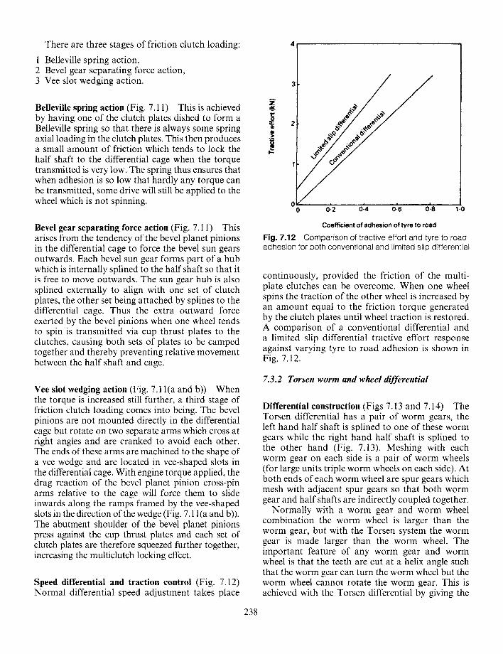
Speed differential and traction control (Fig. 7.12) Normal differential speed adjustment takes place
238
Z
t~
/
0 -- -0:2 :0 :4 0 ;6 0~8 1-0
Coefficient of adhesion of Wre to road
Fig. 7.12 Comparison of tractive effort and tyre to road adhesion for both conventional and limited slip differential
continuously, provided the friction of the multi- plate clutches can be overcome. When one wheel spins the traction of the other wheel is increased by an amount equal to the friction torque generated by the clutch plates until wheel traction is restored. A comparison of a conventional differential and a limited slip differential tractive effort response against varying tyre to road adhesion is shown in Fig. 7.12.
7.3.2 Torsen worm and wheel differential
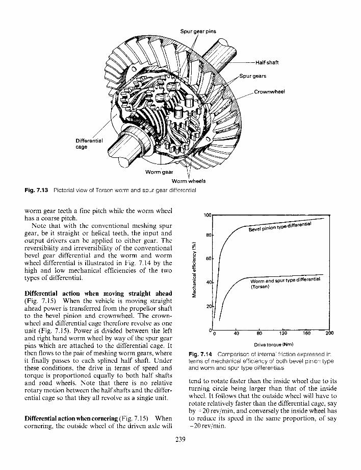
Differential construction (Figs 7.13 and 7.14) The Torsen differential has a pair of worm gears, the left hand half shaft is splined to one of these worm gears while the right hand half shaft is splined to the other hand (Fig. 7.13). Meshing with each worm gear on each side is a pair of worm wheels (for large units triple worm wheels on each side). At both ends of each worm wheel are spur gears which mesh with adjacent spur gears so that both worm gear and half shafts are indirectly coupled together.
Normally with a worm gear and worm wheel combination the worm wheel is larger than the worm gear, but with the Torsen system the worm gear is made larger than the worm wheel. The important feature of any worm gear and worm wheel is that the teeth are cut at a helix angle such that the worm gear can turn the worm wheel but the worm wheel cannot rotate the worm gear. This is achieved with the Torsen differential by giving the
Spur gear pins
/ Differential cage
Worm gear
Half shaft
rownwheel
Worm wheels
Fig. 7.13 Pictorial view of Torsen worm and spur gear differential
worm gear teeth a fine pitch while the worm wheel has a coarse pitch. 100
Note that with the conventional meshing spur gear, be it straight or helical teeth, the input and 80 output drivers can be applied to either gear. The reversibility and irreversibility of the conventional bevel gear differential and the worm and worm °>
~" 6 0
wheel differential is illustrated in Fig. 7.14 by the :~, high and low mechanical efficiencies of the two types of differential.
Differential action when moving straight ahead (Fig. 7.15) When the vehicle is moving straight ahead power is transferred from the propellor shaft to the bevel pinion and crownwheel. The crown- wheel and differential cage therefore revolve as one unit (Fig. 7.15). Power is divided between the left and right hand worm wheel by way of the spur gear pins which are attached to the differential cage. It then flows to the pair of meshing worm gears, where it finally passes to each splined half shaft. Under these conditions, the drive in terms of speed and torque is proportioned equally to both half shafts and road wheels. Note that there is no relative rotary motion between the half shafts and the differ- ential cage so that they all revolve as a single unit.
Differential action when cornering (Fig. 7.15) When cornering, the outside wheel of the driven axle will
239
L ~ f w o r m and spur type differential 40
20
0 0 40 80 120 160 200
Drive torque (Nm)
Fig. 7.14 Comparison of internal friction expressed in terms of mechanical efficiency of both bevel pinion type and worm and spur type differentials
tend to rotate faster than the inside wheel due to its turning circle being larger than that of the inside wheel. It follows that the outside wheel will have to rotate relatively faster than the differential cage, say by +20 rev/min, and conversely the inside wheel has to reduce its speed in the same proportion, of say - 2 0 rev/min.
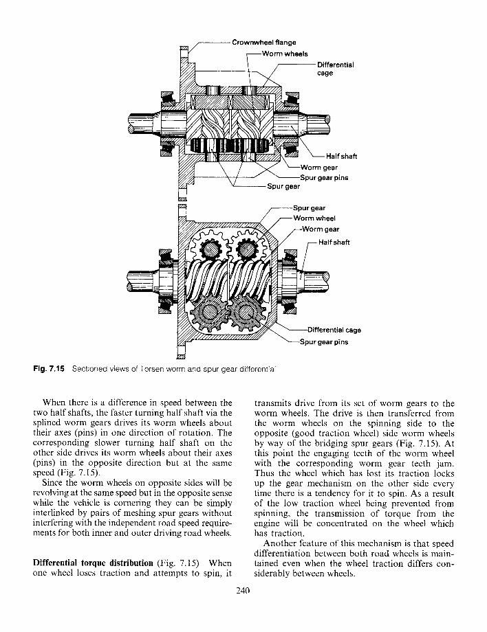
Fig. 7.15
/ - Crownwheel flange ~---Worm wheels
_ _ 1 ..... / ~ Differential
~ ~ \ - - - Half shaft
X / X ~----Worm gear ~ S p u r gear pins
Spur gear
J
~ ~.'//'//./////////2////~
~//////////////7/,7~,
.••Spur gear /----.Worm wheel
f W o r m gear
shaft
. ~ Differential cage
= "----Spur gear pins
Sectioned views of Torsen worm and spur gear differential
When there is a difference in speed between the two half shafts, the faster turning half shaft via the splined worm gears drives its worm wheels about their axes (pins) in one direction of rotation. The corresponding slower turning half shaft on the other side drives its worm wheels about their axes (pins) in the opposite direction but at the same speed (Fig. 7.15).
Since the worm wheels on opposite sides will be revolving at the same speed but in the opposite sense while the vehicle is cornering they can be simply interlinked by pairs of meshing spur gears without interfering with the independent road speed require- ments for both inner and outer driving road wheels.
Differential torque distribution (Fig. 7.15) When one wheel loses traction and attempts to spin, it
240
transmits drive from its set of worm gears to the worm wheels. The drive is then transferred from the worm wheels on the spinning side to the opposite (good traction wheel)side worm wheels by way of the bridging spur gears (Fig. 7.15). At this point the engaging teeth of the worm wheel with the corresponding worm gear teeth jam. Thus the wheel which has lost its traction locks up the gear mechanism on the other side every time there is a tendency for it to spin. As a result of the low traction wheel being prevented from spinning, the transmission of torque from the engine will be concentrated on the wheel which has traction.
Another feature of this mechanism is that speed differentiation between both road wheels is main- tained even when the wheel traction differs con- siderably between wheels.
Thrust block / - - / / - - - -Cross-p in
/ / ~ Planet pinion b,'~///?////Y//,:/A >'4' "[I/A f
1
I . . . . . . !l - -
~i )
Thrust washer
hub ~ / / / / / / , / / / A -Differential cage
Multiplate J
Pc:2kwn ~ - /
mounting flange
Fig. 7.16 Viscous coupling differential
7.3.3 Viscous coupfing differential
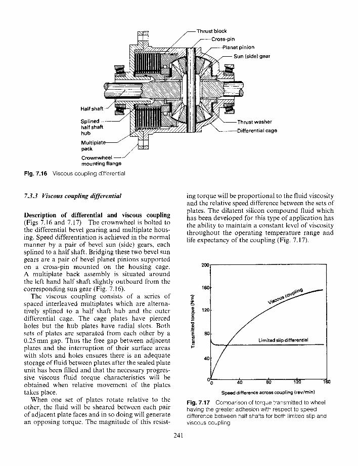
D e s c r i p t i o n o f d i f f e r e n t i a l a n d v i s c o u s c o u p l i n g
(Figs 7.16 and 7.17) The crownwheel is bolted to the differential bevel gearing and multiplate hous- ing. Speed differentiation is achieved in the normal manner by a pair of bevel sun (side) gears, each splined to a half shaft. Bridging these two bevel sun gears are a pair of bevel planet pinions supported on a cross-pin mounted on the housing cage. A multiplate back assembly is situated around the left hand half shaft slightly outboard from the corresponding sun gear (Fig. 7.16).
The viscous coupling consists of a series of spaced interleaved multiplates which are alterna- tively splined to a half shaft hub and the outer differential cage. The cage plates have pierced holes but the hub plates have radial slots. Both sets of plates are separated from each other by a 0.25 mm gap. Thus the free gap between adjacent plates and the interruption of their surface areas with slots and holes ensures there is an adequate storage of fluid between plates after the sealed plate unit has been filled and that the necessary progres- sive viscous fluid torque characteristics will be obtained when relative movement of the plates takes place.
When one set of plates rotate relative to the other, the fluid will be sheared between each pair of adjacent plate faces and in so doing will generate an opposing torque. The magnitude of this resist-
241
ing torque will be proportional to the fluid viscosity and the relative speed difference between the sets of plates. The dilatent silicon compound fluid which has been developed for this type of application has the ability to maintain a constant level of viscosity throughout the operating temperature range and life expectancy of the coupling (Fig. 7.17).
160
I - "
40
! •
0 0 4~0 ' 80 120 160
Speed difference across coupling (rev/rnin)
Fig. 7.17 Comparison of torque transmitted to wheel having the greater adhesion with respect to speed difference between half shafts for both limited slip and viscous coupling
Speed differential action (Fig. 7.16) In the straight ahead driving mode the crownwheel and differen- tial cage driven by the bevel pinion act as the input to the differential gearing and in so doing the power path transfers to the cross-pin and bevel planet gears. One of the functions of these planet gears is to link (bridge) the two sun (side) gears so that the power flow is divided equally between the sun gears and correspondently both half shafts (Fig. 7.16).
When rounding a bend or turning a corner, the outer wheel will have a greater turning circle than the inner one. Therefore the outer wheel tends to increase its speed and the inner wheel decrease its speed relative to the differential cage rotational speed. This speed differential is made possible by the different torque reactions each sun gear con- veys back from the road wheel to the bevel planet pinions. The planet gears 'float' between the sun gears by rotating on their cross-pin, thus the speed lost relative to the cage speed by the inner road wheel and sun gear due to the speed retarding ground reaction will be that gained by the outer road wheel and sun gear.
Viscous coupling action (Figs 7.16 and 7.17) In the situation when one wheel loses traction caused by possibly loose soil, mud, ice or snow, the tyre-road tractive effort reaction is lost. Because of this lost traction there is nothing to prevent the planet pinions revolving on their axes, rolling around the opposite sun gear, which is connected to the road wheel sustaining its traction, with the result that the wheel which has lost its grip will just spin (race) with no power being able to drive the good wheel (Fig. 7.16). Subsequently, a speed difference between the cage plates and half shaft hub plates will be established and in proportion to this relative speed, the two sets of coupling plates will shear the silicon fluid and thereby generate a viscous drag torque between adjacent plate faces (Fig. 7.17). As a result of this viscous drag torque the half shaft hub plates will proportionally resist the rate of fluid shear and so partially lock the differential gear mechanism. A degree of driving torque will be transmitted to the good traction wheel. Fig. 7.17 also compares the viscous coupling differential transmitted torque to the limited slip differential. Here it can be seen that the limited slip differential approximately provides a constant torque to the good traction wheel at all relative speeds, whereas the viscous coupling differential is dependent on speed differences between both half shafts so that
242
the torque transmitted to the wheel supplying trac- tive effort rises with increased relative speed between the half shaft and differential cage.
7.4 Double reduction axles
7.4.1 The need for double reduction final drives The gearbox provides the means to adjust and match the engine's speed and torque so that the vehicle's performance responds to the driver's expectations under the varying operating condi- tions. The gearbox gear reduction ratios are inade- quate to supply the drive axle with sufficient torque multiplication and therefore a further per- manent gear reduction stage is required at the drive axle to produce the necessary road wheel tractive effect. For light vehicles of 0.5-2.0 tonne, a final drive gear reduction between 3.5:1 and 4.5:1 is generally sufficient to meet all normal driving con- ditions, but with commercial vehicles carrying considerably heavier payloads a demand for a much larger final drive gear reduction of 4.5-9.0:1 is essential. This cannot be provided by a single stage final drive crownwheel and pinion without the crownwheel being abnormally large. Double reduction axles partially fulfil the needs for heavy goods vehicles operating under normal conditions by providing two stages of gear reduction at the axle.
In all double reduction final drive arrangements the crownwheel and pinion are used to provide one stage of speed step down. At the same time the bevel gearing redirects the drive perpendicular to the input propellor shaft so that the drive then aligns with the axle half shafts.
7.4.2 Double reduction axles with first stage reduction before the crownwheel and pinion
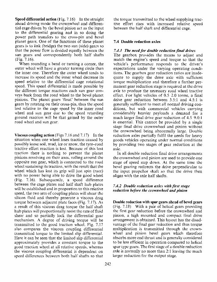
Double reduction with spur gears ahead of bevel gears (Fig. 7.18) With a pair of helical gears providing the first gear reduction before the crownwheel and pinion, a high mounted and compact final drive arrangement is obtained. This layout has the disad- vantage of the final gear reduction and thus torque multiplication is transmitted through the crown- wheel and pinion bevel gears which therefore absorbs more end thrust and is generally considered to be less efficient in operation compared to helical spur type gears. The first stage of a double reduction axle is normally no more than 2:1 leaving the much larger reduction for the output stage.
Input reduc gear
Interme reducti( gear
/ ~ Bevel pinion
Crownwheel
Fig. 7.18 Final drive spur double reduction ahead of bevel pinion
Bevel pinion Crownwheel
Intermediate - pinion gear
" L . ' I Z Z l Z
Final reduction gear
Differential assembly
Fig. 7.19 Final drive spur double reduction between crownwheel and differential
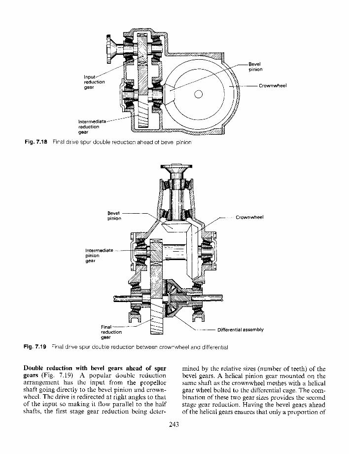
Double reduction with bevel gears ahead of spur gears (Fig. 7.19) A popular double reduction arrangement has the input from the propellor shaft going directly to the bevel pinion and crown- wheel. The drive is redirected at right angles to that of the input so making it flow parallel to the half shafts, the first stage gear reduction being deter-
243
mined by the relative sizes (number of teeth) of the bevel gears. A helical pinion gear mounted on the same shaft as the crownwheel meshes with a helical gear wheel bolted to the differential cage. The com- bination of these two gear sizes provides the second stage gear reduction. Having the bevel gears ahead of the helical gears ensures that only a proportion of
torque multiplication will be constrained by them, while the helical gears will absorb the full torque reaction of the final gear reduction.
7.4.3 Inboard and outboard double reduction axles Where very heavy loads are to be carried by on-off highway vehicles, the load imposed on the crown- wheel and pinion and differential unit can be reduced by locating a further gear reduction on either side of the differential exit. If the second gear reduction is arranged on both sides close to the differential cage, it is referred to as an inboard reduction. They can be situated at the wheel ends of the half shafts, where they are known as outboard second stage gear reduction. By having the reduc- tion directly after the differential, the increased torque multiplication will only be transmitted to the half shafts leaving the crownwheel, pinion and differential with a torque load capacity propor- tional to their gear ratio. The torque at this point may be smaller than with the normal final drive gear ratio since less gear reduction will be needed at the crownwheel and pinion if a second reduction is to be provided. Alternatively, if the second reduc- tion is in the axle hub, less torque will be trans- mitted by the half shafts and final drive differential and the dimensions of these components can be kept to a minimum. Having either an inboard or outboard second stage gear reduction enables lighter crownwheel and pinion combinations and differential assembly to be employed, but it does mean there are two gear reductions for each half
shaft, as opposed to a single double reduction drive if the reduction takes place before the differential.
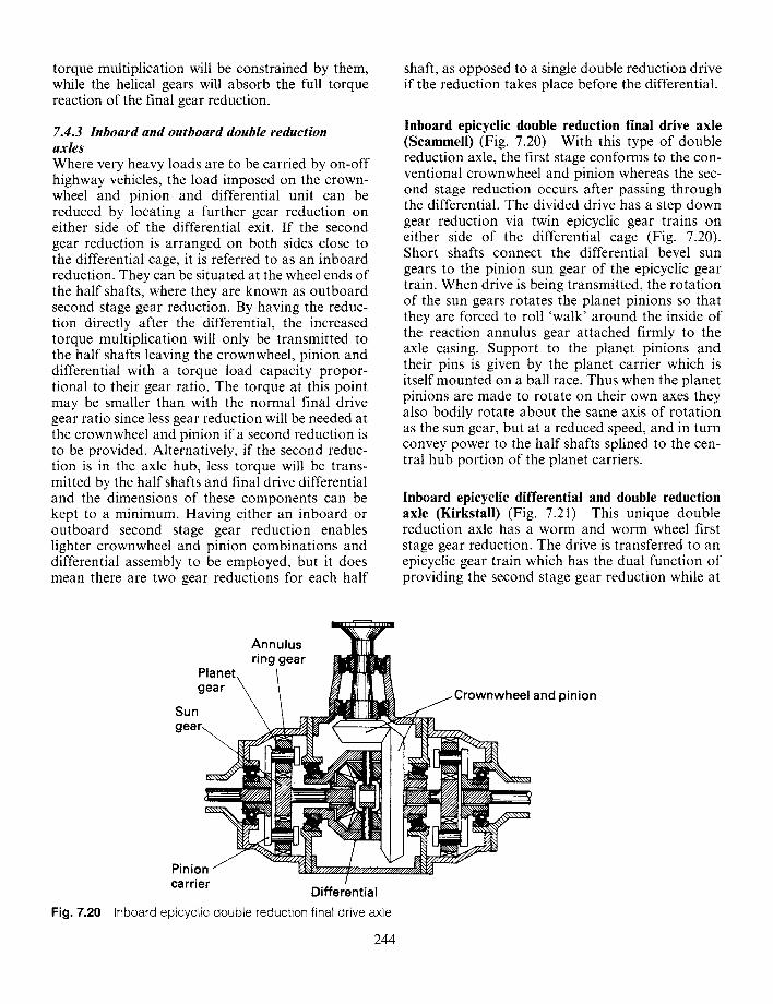
Inboard epicyclic double reduction final drive axle (Scammell) (Fig. 7.20) With this type of double reduction axle, the first stage conforms to the con- ventional crownwheel and pinion whereas the sec- ond stage reduction occurs after passing through the differential. The divided drive has a step down gear reduction via twin epicyclic gear trains on either side of the differential cage (Fig. 7.20). Short shafts connect the differential bevel sun gears to the pinion sun gear of the epicyclic gear train. When drive is being transmitted, the rotation of the sun gears rotates the planet pinions so that they are forced to roll 'walk' around the inside of the reaction annulus gear attached firmly to the axle casing. Support to the planet pinions and their pins is given by the planet carrier which is itself mounted on a ball race. Thus when the planet pinions are made to rotate on their own axes they also bodily rotate about the same axis of rotation as the sun gear, but at a reduced speed, and in turn convey power to the half shafts splined to the cen- tral hub portion of the planet carriers.
Inboard epicyclic differential and double reduction axle (Kirkstall) (Fig. 7.21) This unique double reduction axle has a worm and worm wheel first stage gear reduction. The drive is transferred to an epicyclic gear train which has the dual function of providing the second stage gear reduction while at
Fig. 7.20
Annulus ring gear [llll II]I[IW
Planet. ~ gear ~ \ ~ ~111~ Sun ~ \ ~ C r o w n w h e e l a n d p i n i o n
g e a r ~ ~ ~ ( z ~ ~, f ~
Pinion carrier ! Differential
Inboard epicyclic double reduction final drive axle
244
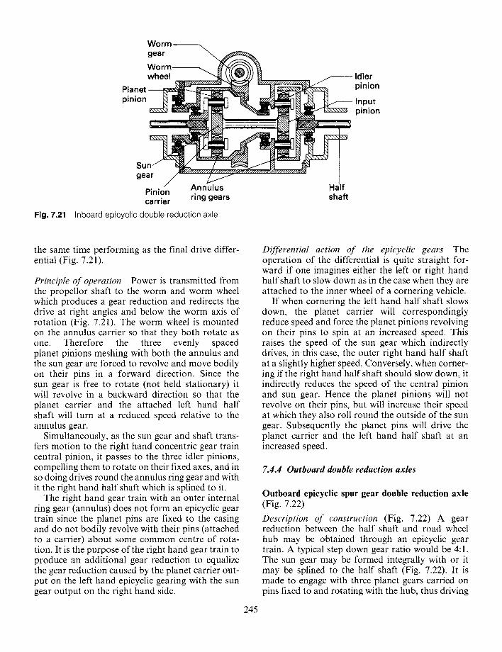
Fig. 7.21
W o r m L _ gear
W o r m. ~ ~ "{.ff~-',~'~'~ '~ wheel ~ k \ \ ~ ) ) / ~ f ~ ~ ' ~ ' ~ / " ~ " ~ ' ¢ ~ r~-z~/////////////~K~v" / I d le r
P I a n et " ~ ~ 7 / 7 A q~J ~,\\.,.,,~,,,gl~k~ . . . . p i n t o n
pinion ~ ~ In.p.ut
- - - - 1
un. r Pinion carrier ring gears shaft
Inboard ep icyc l i c doub le reduct ion axle
the same time performing as the final drive differ- ential (Fig. 7.21).
Principle of operation Power is transmitted from the propellor shaft to the worm and worm wheel which produces a gear reduction and redirects the drive at right angles and below the worm axis of rotation (Fig. 7.21). The worm wheel is mounted on the annulus carrier so that they both rotate as one. Therefore the three evenly spaced planet pinions meshing with both the annulus and the sun gear are forced to revolve and move bodily on their pins in a forward direction. Since the sun gear is free to rotate (not held stationary) it will revolve in a backward direction so that the planet carrier and the attached left hand half shaft will turn at a reduced speed relative to the annulus gear.
Simultaneously, as the sun gear and shaft trans- fers motion to the right hand concentric gear train central pinion, it passes to the three idler pinions, compelling them to rotate on their fixed axes, and in so doing drives round the annulus ring gear and with it the right hand half shaft which is splined to it.
The right hand gear train with an outer internal ring gear (annulus) does not form an epicyclic gear train since the planet pins are fixed to the casing and do not bodily revolve with their pins (attached to a carrier) about some common centre of rota- tion. It is the purpose of the right hand gear train to produce an additional gear reduction to equalize the gear reduction caused by the planet carrier out- put on the left hand epicyclic gearing with the sun gear output on the right hand side.
245
Differential action of the epicyclic gears The operation of the differential is quite straight for- ward if one imagines either the left or right hand half shaft to slow down as in the case when they are attached to the inner wheel of a cornering vehicle.
If when cornering the left hand half shaft slows down, the planet carrier will correspondingly reduce speed and force the planet pinions revolving on their pins to spin at an increased speed. This raises the speed of the sun gear which indirectly drives, in this case, the outer right hand half shaft at a slightly higher speed. Conversely, when corner- ing if the right hand half shaft should slow down, it indirectly reduces the speed of the central pinion and sun gear. Hence the planet pinions will not revolve on their pins, but will increase their speed at which they also roll round the outside of the sun gear. Subsequently the planet pins will drive the planet carrier and the left hand half shaft at an increased speed.
7.4.4 Outboard double reduction axles
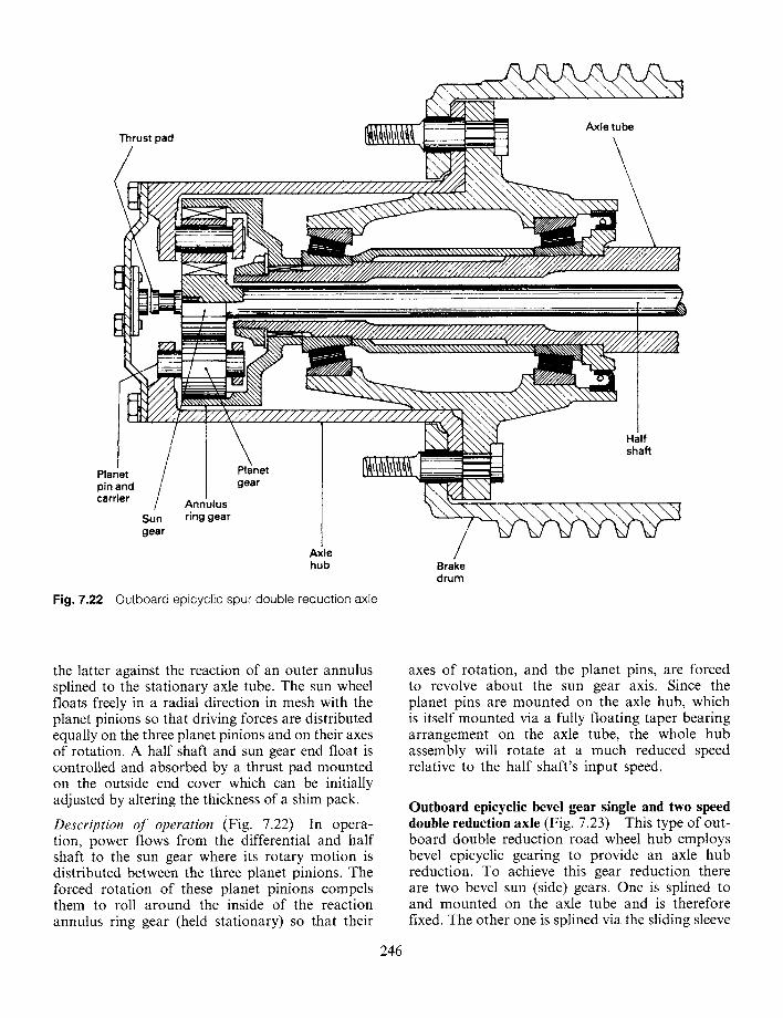
Outboard epicyclic spur gear double reduction axle (Fig. 7.22)
Description of construction (Fig. 7.22) A gear reduction between the half shaft and road wheel hub may be obtained through an epicyclic gear train. A typical step down gear ratio would be 4:1. The sun gear may be formed integrally with or it may be splined to the half shaft (Fig. 7.22). It is made to engage with three planet gears carried on pins fixed to and rotating with the hub, thus driving
Thrust pad Axle tube
Planet pin and carrier
Sun gear
Annulus ring gear
Planet gear
Axle hub
Fig. 7.22 Outboard epicyclic spur double reduction axle
Brake drum
Half shaft
the latter against the reaction of an outer annulus splined to the stationary axle tube. The sun wheel floats freely in a radial direction in mesh with the planet pinions so that driving forces are distributed equally on the three planet pinions and on their axes of rotation. A half shaft and sun gear end float is controlled and absorbed by a thrust pad mounted on the outside end cover which can be initially adjusted by altering the thickness of a shim pack.
Description of operation (Fig. 7.22) In opera- tion, power flows from the differential and half shaft to the sun gear where its rotary motion is distributed between the three planet pinions. The forced rotation of these planet pinions compels them to roll around the inside of the reaction annulus ring gear (held stationary) so that their
246
axes of rotation, and the planet pins, are forced to revolve about the sun gear axis. Since the planet pins are mounted on the axle hub, which is itself mounted via a fully floating taper bearing arrangement on the axle tube, the whole hub assembly will rotate at a much reduced speed relative to the half shaft's input speed.
Outboard epicyclic bevel gear single and two speed double reduction axle (Fig. 7.23) This type of out- board double reduction road wheel hub employs bevel epicyclic gearing to provide an axle hub reduction. To achieve this gear reduction there are two bevel sun (side) gears. One is splined to and mounted on the axle tube and is therefore fixed. The other one is splined via the sliding sleeve
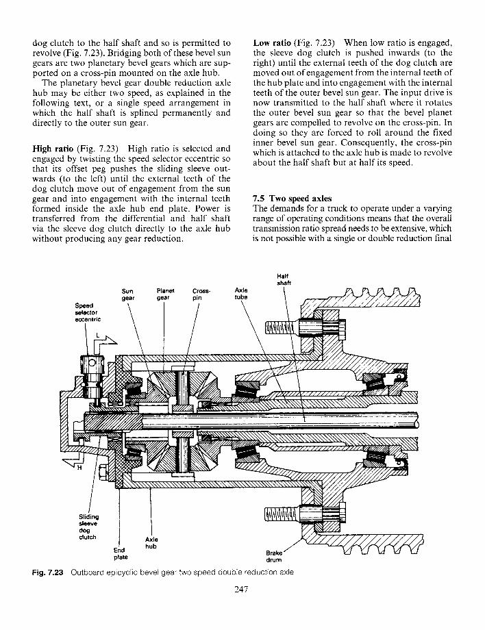
dog clutch to the half shaft and so is permitted to revolve (Fig. 7.23). Bridging both of these bevel sun gears are two planetary bevel gears which are sup- ported on a cross-pin mounted on the axle hub.
The planetary bevel gear double reduction axle hub may be either two speed, as explained in the following text, or a single speed arrangement in which the half shaft is splined permanently and directly to the outer sun gear.
High ratio (Fig. 7.23) High ratio is selected and engaged by twisting the speed selector eccentric so that its offset peg pushes the sliding sleeve out- wards (to the left) until the external teeth of the dog clutch move out of engagement from the sun gear and into engagement with the internal teeth formed inside the axle hub end plate. Power is transferred from the differential and half shaft via the sleeve dog clutch directly to the axle hub without producing any gear reduction.
Low ratio (Fig. 7.23) When low ratio is engaged, the sleeve dog clutch is pushed inwards (to the right) until the external teeth of the dog clutch are moved out of engagement from the internal teeth of the hub plate and into engagement with the internal teeth of the outer bevel sun gear. The input drive is now transmitted to the half shaft where it rotates the outer bevel sun gear so that the bevel planet gears are compelled to revolve on the cross-pin. In doing so they are forced to roll around the fixed inner bevel sun gear. Consequently, the cross-pin which is attached to the axle hub is made to revolve about the half shaft but at half its speed.
7.5 Two speed axles The demands for a truck to operate under a varying range of operating conditions means that the overall transmission ratio spread needs to be extensive, which is not possible with a single or double reduction final
Speed selector eccentric
Half shaft
Sun Planet Cross- Axle gear gear pin tube
\ / \ 1
h, , r , / ~ /
_
Sliding sleeve dog clutch
~\\\\'<,NN\\\\\\",,\\\',~ ~ N U / ~ ; / , ?
Axle hub
End Brake plate drum
Fig. 7.23 Outboard epicyclic bevel gear two speed double reduction axle
247
Input flange coupling
Bevel pinion
,---- Crownwheel
Intermediate pinion gear (low)
Intermediate pinion gear (high)
Intermediate pinion shaft
Constant mesh sliding dog clutch
~ -~ Half shaft
Final reduction j gea r (low)
Fig. 7.24 Two speed double reduction helical gear axle
Planet gear
,Cross-pin
Sun (side) gear
Final reduction gear (high)
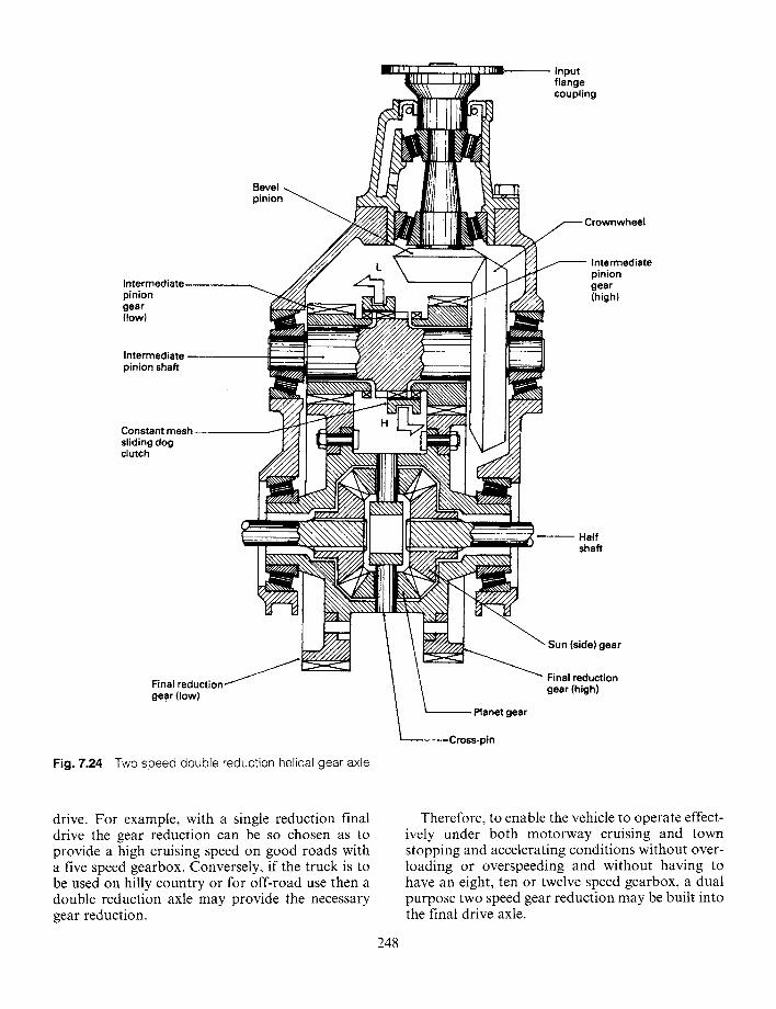
drive. For example, with a single reduction final drive the gear reduction can be so chosen as to provide a high cruising speed on good roads with a five speed gearbox. Conversely, if the truck is to be used on hilly country or for off-road use then a double reduction axle may provide the necessary gear reduction.
248
Therefore, to enable the vehicle to operate effect- ively under both motorway cruising and town stopping and accelerating conditions without over- loading or overspeeding and without having to have an eight, ten or twelve speed gearbox, a dual purpose two speed gear reduction may be built into the final drive axle.
Combining a high and low ratio in the same axle doubles the number of gears available from the standard gearbox. The low range of gears will then provide the maximum pulling power for heavy duty operations on rough roads, whereas the high range of gears allows maximum speed when conditions are favourable. From the wide range of gear ratios the driver can choose the exact combination to suit any conditions of load and road so that the engine will always operate at peak efficiency and near to its maximum torque speed band.
7.5.1 Two speed double reduction helical gear axle (Rockwell-Standard) (Fig. 7.24) This two speed double reduction helical gear axle has a conventional crownwheel and bevel pinion single speed first reduction with a second stage speed reduction consisting of two pairs of adjacent pinion and wheel helical cut gears. These pinions mounted on the crownwheel support shaft act as intermediate gears linking the crownwheel to the differential cage final reduction wheel gears (Fig. 7.24).
Low ratio (Fig. 7.24) Low ratio is engaged when the central sliding dog clutch splined to the crown- wheel shaft slides over the selected (left hand) low speed smaller pinion dog teeth. Power from the propellor shaft now flows to the bevel pinion where it is redirected at right angles to the crown- wheel and shaft. From here it passes from the locked pinion gear and crownwheel to the final reduction wheel gear bolted to the differential cage. The drive is then divided via the differential cross-pin and planet pinions between both sun gears where it is transmitted finally to the half shafts and road wheels.
High ratio (Fig. 7.24) High ratio is engaged in a similar way as for low ratio but the central sliding dog clutch slides in the opposite direction (right hand) over the larger pinion dog teeth. The slightly larger pinion meshing with a correspondently smaller differential wheel gear produces a more direct second stage reduction and hence a higher overall final drive axle gear ratio.
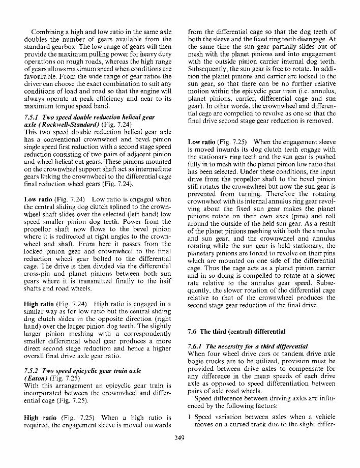
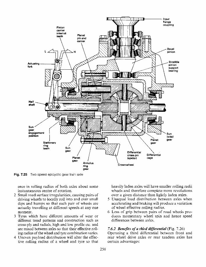
7.5.2 Two speed epicyclic gear train axle (Eaton) (Fig. 7.25) With this arrangement an epicyclic gear train is incorporated between the crownwheel and differ- ential cage (Fig. 7.25).
High ratio (Fig. 7.25) When a high ratio is required, the engagement sleeve is moved outwards
249
from the differential cage so that the dog teeth of both the sleeve and the fixed ring teeth disengage. At the same time the sun gear partially slides out of mesh with the planet pinions and into engagement with the outside pinion cartier internal dog teeth. Subsequently, the sun gear is free to rotate. In addi- tion the planet pinions and carrier are locked to the sun gear, so that there can be no further relative motion within the epicyclic gear train (i.e. annulus, planet pinions, cartier, differential cage and sun gear). In other words, the crownwheel and differen- tial cage are compelled to revolve as one so that the final drive second stage gear reduction is removed.
Low ratio (Fig. 7.25) When the engagement sleeve is moved inwards its dog clutch teeth engage with the stationary ring teeth and the sun gear is pushed fully in to mesh with the planet pinion low ratio that has been selected. Under these conditions, the input drive from the propellor shaft to the bevel pinion still rotates the crownwheel but now the sun gear is prevented from turning. Therefore the rotating crownwheel with its internal annulus ring gear revol- ving about the fixed sun gear makes the planet pinions rotate on their own axes (pins) and roll around the outside of the held sun gear. As a result of the planet pinions meshing with both the annulus and sun gear, and the crownwheel and annulus rotating while the sun gear is held stationary, the planetary pinions are forced to revolve on their pins which are mounted on one side of the differential cage. Thus the cage acts as a planet pinion carrier and in so doing is compelled to rotate at a slower rate relative to the annulus gear speed. Subse- quently, the slower rotation of the differential cage relative to that of the crownwheel produces the second stage gear reduction of the final drive.
7.6 The third (central) differential
7.6.1 The necessity for a third differential When four wheel drive cars or tandem drive axle bogie trucks are to be utilized, provision must be provided between drive axles to compensate for any difference in the mean speeds of each drive axle as opposed to speed differentiation between pairs of axle road wheels.
Speed difference between driving axles are influ- enced by the following factors:
1 Speed variation between axles when a vehicle moves on a curved track due to the slight differ-
Actuating fork
Pinion carrier internal teeth Planet
pin and carrier
Input flange coupling
Bevel pinion
pinion supporl bearing
Half shaft
Sun f gear: engagement position
Stationary ring teeth Sun
gear
Planet gear
/ Annulus ring gear
Fig. 7.25 Two speed epicyclic gear train axle
l Differential cross-pin (spider)
Crownwheel
Planet gear
Differential cage
Sun (side) gear
ence in rolling radius of both axles about some instantaneous centre of rotation.
2 Small road surface irregularities, causing pairs of driving wheels to locally roll into and over small dips and humps so that each pair of wheels are actually travelling at different speeds at any one moment.
3 Tyres which have different amounts of wear or different tread patterns and construction such as cross-ply and radials, high and low profile etc. and are mixed between axles so that their effective roll- ing radius of the wheel and tyre combination varies.
4 Uneven payload distribution will alter the effec- tive rolling radius of a wheel and tyre so t h a t
250
heavily laden axles will have smaller rolling radii wheels and therefore complete more revolutions over a given distance than lightly laden axles.
5 Unequal load distribution between axles when accelerating and braking will produce a variation of wheel effective rolling radius.
6 Loss of grip between pairs of road wheels pro- duces momentary wheel spin and hence speed differences between axles.
7.6.2 Benefits of a third differential (Fig. 7.26) Operating a third differential between front and rear wheel drive axles or rear tandem axles has certain advantages:
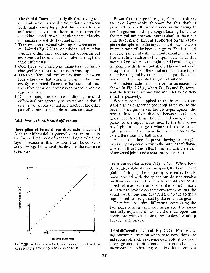
1 The third differential equally divides driving tor- que and provides speed differentiation between both final drive axles so that the relative torque and speed per axle are better able to meet the individual road wheel requirements, thereby minimizing tyre distortion and scrub.
2 Transmission torsional wind-up between axles is minimized (Fig. 7.26) since driving and reaction torques within each axle are not opposing but are permitted to equalize themselves through the third differential.
3 Odd tyres with different diameters are inter- changeable without transmission wind-up.
4 Tractive effect and tyre grip is shared between four wheels so that wheel traction will be more evenly distributed. Therefore the amount of trac- tive effect per wheel necessary to propel a vehicle can be reduced.
5 Under slippery, snow or ice conditions, the third differential can generally be locked-out so that if one pair of wheels should lose traction, the other pair of wheels are still able to transmit traction.
7.6.3 Inter axle with third differential
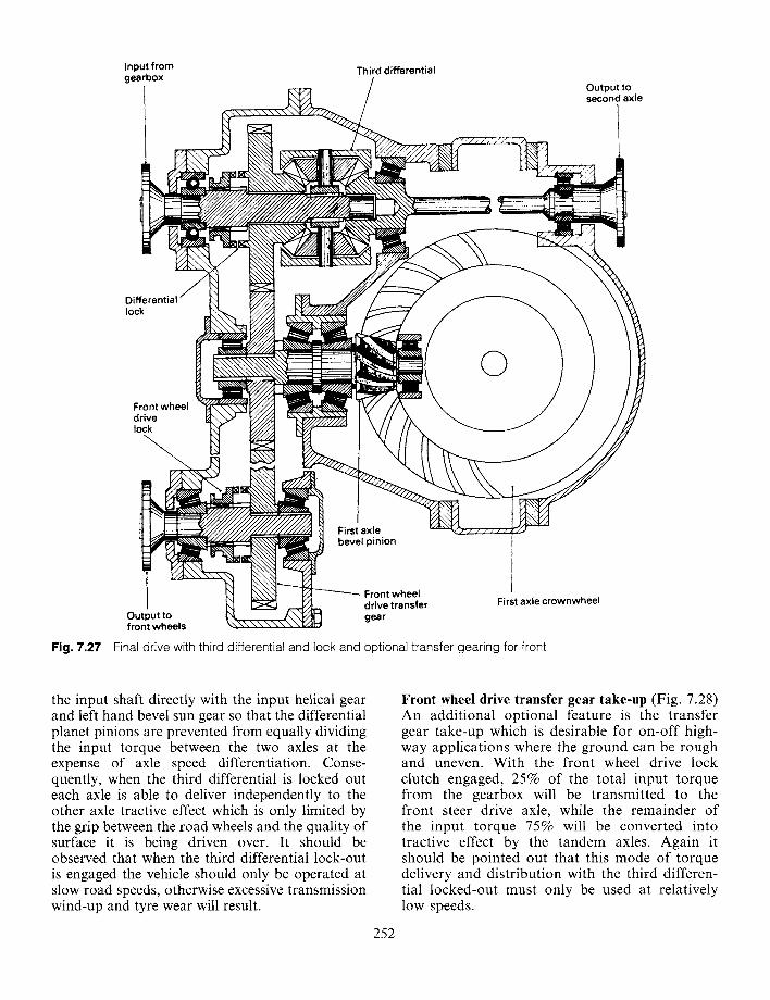
Description of forward rear drive axle (Fig. 7.27) A third differential is generally incorporated in the forward rear axle of a tandem bogie axle drive layout because in this position it can be conveni- ently arranged to extend the drive to the rear axle (Fig. 7.27).
0 0.5 1.0 1-5
A
3
¢D
.> 2 m
¢D t r
2.0
Torsional twist (deg)
Fig. 7.26 Relationship of relative speeds of double drive axles and the amount of transmission twist
251
Power from the gearbox propellor shaft drives the axle input shaft. Support for this shaft is provided by a ball race mounted in the casing at the flanged end and by a spigot bearing built into the integral sun gear and output shaft at the other end. Bevel planet pinions supported on the cross- pin spider splined to the input shaft divide the drive between both of the bevel sun gears. The left hand sun gear is integral with the input helical gear and is free to rotate relative to the input shaft which it is mounted on, whereas the right hand bevel sun gear is integral with the output shaft. This output shaft is supported at the differential end by a large taper roller bearing and by a much smaller parallel roller bearing at the opposite flanged output end.
A tandem axle transmission arrangement is shown in Fig. 7.28(a) where D1, D2 and D3 repre- sent the first axle, second axle and inter axle differ- ential respectively.
When power is supplied to the inter axle (for- ward rear axle) through the input shaft and to the bevel planet pinion via the cross-pin spider, the power flow is then divided between both sun gears. The drive from the left hand sun gear then passes to the input helical gear to the final drive bevel pinion helical gear where it is redirected at right angles by the crownwheel and pinion to the axle differential and half shafts.
At the same time the power flowing to the right hand sun gear goes directly to the output shaft flange where it is then transmitted to the rear axle via a pair of universal joints and a short propellor shaft.
Third differential action (Fig. 7.27) When both drive axles rotate at the same speed, the bevel planet pinions bridging the opposing sun gears bodily move around with the spider but do not revolve on their own axes. If one axle should reduce its speed relative to the other one, the planet pinions will start to revolve on their cross-pins so that the speed lost by one sun gear relative to the spider's input speed will be gained by the other sun gear.
Therefore the third differential connecting the two axles permits each axle mean speed to auto- matically adjust itself to suit the road operating conditions without causing any torsional wind-up between axle drives.
Third differential lock-out (Fig. 7.27) For provid- ing maximum traction when road conditions are unfavourable such as driving over soft, slippery or steep ground, a differential lock-out clutch is incorporated. When engaged this device couples
Input from gearbox
Third differential
Output to second axle
Differential lock
O Front wheel drive lock
z
Output to ~ _
front wheels ~\"
Firs ax!e
~ ' - ' ~ bevel pinion
~ ~ Front wheel \ \ \ \ \ \ \ I Z I H dee e transfer
i 1
First axle crownwheel
Fig. 7.27 Final drive with third differential and lock and optional transfer gearing for front
the input shaft directly with the input helical gear and left hand bevel sun gear so that the differential planet pinions are prevented from equally dividing the input torque between the two axles at the expense of axle speed differentiation. Conse- quently, when the third differential is locked out each axle is able to deliver independently to the other axle tractive effect which is only limited by the grip between the road wheels and the quality of surface it is being driven over. It should be observed that when the third differential lock-out is engaged the vehicle should only be operated at slow road speeds, otherwise excessive transmission wind-up and tyre wear will result.
252
Front wheel drive transfer gear take-up (Fig. 7.28) An additional optional feature is the transfer gear take-up which is desirable for on-off high- way applications where the ground can be rough and uneven. With the front wheel drive lock clutch engaged, 25% of the total input torque from the gearbox will be transmitted to the front steer drive axle, while the remainder of the input torque 75% will be converted into tractive effect by the tandem axles. Again it should be pointed out that this mode of torque delivery and distribution with the third differen- tial locked-out must only be used at relatively low speeds.
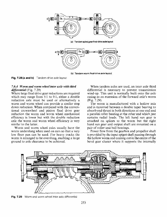
(a) Tandem spiral gear final-drive axle layout
(b) Tandem worm final-drive axle layout
Fig. 7.28(a and b) Tandem drive axle layout
7.6.4 W o r m and worm wheel inter axle with third differential (Fig. 7.29) Where large final drive gear reductions are required which may range from 5:1 to 9:1, either a double reduction axle must be used or alternatively a worm and worm wheel can provide a similar step down reduction. When compared with the conven- tional crownwheel and pinion final drive gear reduction the worm and worm wheel mechanical efficiency is lower but with the double reduction axle the worm and worm wheel efficiency is very similar to the latter.
Worm and worm wheel axles usually have the worm underslung when used on cars so that a very low floor pan can be used. For heavy trucks the worm is arranged to be overslung, enabling a large ground to axle clearance to be achieved.
When tandem axles are used, an inter axle third differential is necessary to prevent transmission wind-up. This unit is normally built onto the axle casing as an extension of the forward axle's worm (Fig. 7.29).
The worm is manufactured with a hollow axis and is mounted between a double taper bearing to absorb end thrust in both directions at one end and a parallel roller bearing at the other end which just sustains radial loads. The left hand sun gear is attached on splines to the worm but the right hand sun gear and output shaft are mounted on a pair of roller and ball bearings.
Power flow from the gearbox and propellor shaft is provided by the input spigot shaft passing through the hollow worm and coming out in the centre of the bevel gear cluster where it supports the internally
/ / /
/
Fig. 7.29 Worm and worm wheel inter axle differential
\ \
253
splined cross-pin spider and their corresponding planet pinions. Power is then split between the front axle (left hand) sun gear and worm and the rear axle (right hand) sun gear and output shaft, thus transmitting drive to the second axle.
Consequently if the two axle speeds should vary, as for example when cornering, the planet pinions will revolve on their axes so that the sun gears are able to rotate at speeds slightly above and below that of the input shaft and spider, but at the same time still equally divide the torque between both axles.
Fig. 7.28(b) shows the general layout of a tan- dem axle worm and worm wheel drive where Dz, D2 and D3 represent the first axle, second axle and inter axle differentials respectively.
7.7 Four wheel drive arrangements
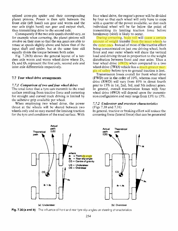
7.7.1 Comparison o f two and four wheel drives The total force that a tyre can transmit to the road surface resulting from tractive force and cornering for straight and curved track driving is limited by the adhesive grip available per wheel.
When employing two wheel drive, the power thrust at the wheels will be shared between two wheels only and so may exceed the limiting traction for the tyre and condition of the road surface. With
four wheel drive, the engine's power will be divided by four so that each wheel will only have to cope with a quarter of the power available, so that each individual wheel will be far below the point of transmitting its limiting traction force before breakaway (skid) is likely to occur.
During cornering, body roll will cause a certain amount of weight transfer from the inner wheels to the outer ones. Instead of most of the tractive effort being concentrated on just one driving wheel, both front and rear outer wheels will share the vertical load and driving thrust in proportion to the weight distribution between front and rear axles. Thus a four wheel drive (4WD) when compared to a two wheel drive (2WD) vehicle has a much greater mar- gin of safety before tyre to ground traction is lost.
Transmission losses overall for front wheel drive (FWD) are in the order of 10%, whereas rear wheel drive (RWD) will vary from 10% in direct fourth gear to 13% in 1st, 2nd, 3rd, and 5th indirect gears. In general, overall transmission losses with four wheel drive (4WD) will depend upon the transmis- sion configuration and may range from 13% to 15%.
7.7.2 Understeer and oversteer characteristics (Figs 7.30 and 7.31) In general, tractive or braking effort will reduce the cornering force (lateral force) that can be generated
Theoretical path ~1~
Actual path (us)
Actual Theoretical path path (OS) ~. . t=
~=>eR
where OF = Front slipangte #R = Rear slip angle CG = Centre of gravity
US = Understeer OS = Oversteer
#R
co /I-- R
(a) Understeer (b) Oversteer
Fig. 7.30 (a and b) The influence of front and rear tyre slip angles on steering characteristics
254
zhe huang
Highlight
zhe huang
Highlight
zhe huang
Highlight
zhe huang
Highlight
zhe huang
Highlight
zhe huang
Highlight
zhe huang
Highlight
zhe huang
Line
zhe huang
Highlight
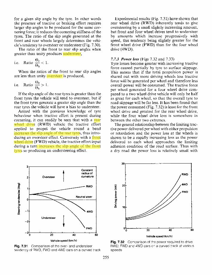
i .e.
i .e.
OF Ratio ~ < 1.
When the ratios of the front to rear slip angles are less than unity oversteer is produced,
8 @
o @
O) ¢ - "¢::
~ -1
~F Ratio ~ > 1.
If the slip angle of the rear tyres is greater than the front tyres the vehicle will tend to oversteer, but if the front tyres generate a greater slip angle than the rear tyres the vehicle will have a bias to understeer.
Armed with the previous knowledge of tyre behaviour when tractive effort is present during cornering, it can readily be seen that with a rear wheel drive (RWD) vehicle the tractive effort applied to propel the vehicle round a bend increases the slip angle of the rear tyres, thus intro- ducing an oversteer effect. Conversely with a front wheel drive (FWD) vehicle, the tractive effort input during a turn increases the slip angle of the front tyres so producing an understeering effect.
Experimental results (Fig. 7.31) have shown that rear wheel drive (RWD) inherently tends to give oversteering by a small slightly increasing amount, but front and four wheel drives tend to understeer by amounts which increase progressively with speed, this tendency being slightly greater for the front wheel drive (FWD) than for the four wheel drive (4WD).
7.7.3 Power loss (Figs 7.32 and 7.33) Tyre losses become greater with increasing tractive force caused partially by tyre to surface slippage. This means that if the total propulsion power is shared out with more driving wheels less tractive force will be generated per wheel and therefore less overall power will be consumed. The tractive force per wheel generated for a four wheel drive com- pared to a two wheel drive vehicle will only be half as great for each wheel, so that the overall tyre to road slippage will be far less. It has been found that the power consumed (Fig. 7.32) is least for the front wheel drive and greatest for the rear wheel drive, while the four wheel drive loss is somewhere in between the other two extremes.
The general relationship between the limiting trac- tive power delivered per wheel with either propulsion or retardation and the power loss at the wheels is shown to be a rapidly increasing loss as the power delivered to each wheel approaches the limiting adhesion condition of the road surface. Thus with a dry road the power loss is relatively small with
-2
Oversteer
-3 I 0
Fig. 7.31
RWD
Constant T radius of
cu rvatu re
30
Neutral steer
Understeer
4WD
~ D I I , I I |
20 4O 60
Vehicle speed (km/h)
Comparison of the over- and understeer tendency of RWD, FWD and 4WD cars on a curved track
255
RWD
4WD
FWD
2O v
j= g ==
10
for a given slip angle by the tyre. In other words the presence of tractive or braking effort requires larger slip angles to be produced for the same cor- nering force; it reduces the cornering stiffness of the tyres. The ratio of the slip angle generated at the front and rear wheels largely determines the vehi- cle's tendency to oversteer or understeer (Fig. 7.30).
The ratio of the front to rear slip angles when greater than unity produces understeer,
' ~0 80 °o ~o ' . . . .
Vehicle speed (kin/h)
Fig. 7.32 Comparison of the power required to drive RWD, FWD and 4WD cars on a curved track at various speeds
zhe huang
Highlight
zhe huang
Highlight
zhe huang
Highlight
zhe huang
Highlight
zhe huang
Highlight
zhe huang
Highlight
zhe huang
Line
zhe huang
Line
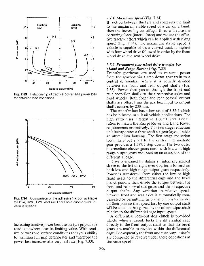
Traction Braking 10 limit limit 10
8 / z= 0.3 8 A
0-3
6 /~ = 0.6 6 _.o
i 0.6 ~" 4 4
0 ~ ~ - ~ - - - 0 40 20 0 20 40
Tractive power (kW)
Fig. 7.33 Relationship of tractive power and power loss for different road conditions
O ! ' I
RWD FWD 4WD
.,.,..
v g
L
8 .g: • o 1
20' '-- 40 60
Vehicle speed (km/h)
Fig. 7.34 Comparison of the adhesive traction available to Drive, RWD, FWD and 4WD cars on a curved track at various speeds
increasing tractive power because the tyre grip on the road is nowhere near its limiting value. With semi- wet or wet road surface conditions the tyre's ability to maintain full grip deteriorates and therefore the power loss increases at a very fast rate (Fig. 7.33).
256
7.7.4 Maximum speed (Fig. 7.34) If friction between the tyre and road sets the limit to the maximum stable speed of a car on a bend, then the increasing centrifugal force will raise the cornering force (lateral force) and reduce the effec- tive tractive effort which can be applied with rising speed (Fig. 7.34). The maximum stable speed a vehicle is capable of on a curved track is highest with four wheel drive followed in order by the front wheel drive and rear wheel drive.
7.7.5 Permanent four wheel drive transfer box (Land and Range Rover) (Fig. 7.35) Transfer gearboxes are used to transmit power from the gearbox via a step down gear train to a central differential, where it is equally divided between the front and rear output shafts (Fig. 7.35). Power then passes through the front and rear propellor shafts to their respective axles and road wheels. Both front and rear coaxial output shafts are offset from the gearbox input to output shafts centres by 230 mm.
The transfer box has a low ratio of 3.32:1 which has been found to suit all vehicle applications. The high ratio uses alternative 1.003:1 and 1.667:1 ratios to match the Range Rover and Land Rover requirements respectively. This two stage reduction unit incorporates a three shaft six gear layout inside an aluminium housing. The first stage reduction from the input shaft to the central intermediate gear provides a 1.577:1 step down. The two outer intermediate cluster gears mesh with low and high range output gears mounted on an extension of the differential cage.
Drive is engaged by sliding an internally splined sleeve to the left or right over dog teeth formed on both low and high range output gears respectively. Power is transferred from either the low or high range gears to the differential cage and the bevel planet pinions then divide the torque between the front and rear bevel sun gears and their respective output shafts. Any variation in relative speeds between front and rear axles is automatically com- pensated by permitting the planet pinions to revolve on their pins so that speed lost by one output shaft will be equal to that gained by the other output shaft relative to the differential cage input speed.
A differential lock-out dog clutch is provided which, when engaged, locks the differential cage directly to the front output shaft so that the bevel gears are unable to revolve within the differential cage. Consequently the front and rear output shafts are compelled to revolve under these conditions at the same speed.
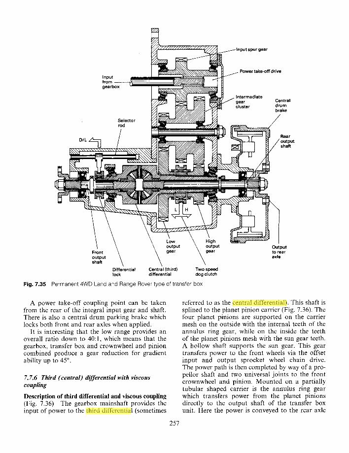
spurgear
Input from - - - - - - - gearbox
Selector rod
Power take-off drive
Intermediate gear cluster
Central drum brake
Rear output shaft
Fig. 7.35
Front output shaft
Low output gear
High output gear
Differential Central (third) Two speed lock differential dog clutch
Permanent 4WD Land and Range Rover type of transfer box
Output to rear axle
A power take-off coupling point can be taken from the rear of the integral input gear and shaft. There is also a central drum parking brake which locks both front and rear axles when applied.
It is interesting that the low range provides an overall ratio down to 40:1, which means that the gearbox, transfer box and crownwheel and pinion combined produce a gear reduction for gradient ability up to 45 ° .
7.7.6 Third (central) differential with viscous coupling
Description of third differential and viscous coupling (Fig. 7.36) The gearbox mainshaft provides the input of power to the third differential (sometimes
257
referred to as the central differential). This shaft is splined to the planet pinion carrier (Fig. 7.36). The four planet pinions are supported on the carrier mesh on the outside with the internal teeth of the annulus ring gear, while on the inside the teeth of the planet pinions mesh with the sun gear teeth. A hollow shaft supports the sun gear. This gear transfers power to the front wheels via the offset input and output sprocket wheel chain drive. The power path is then completed by way of a pro- pellor shaft and two universal joints to the front crownwheel and pinion. Mounted on a partially tubular shaped carrier is the annulus ring gear which transfers power from the planet pinions directly to the output shaft of the transfer box unit. Here the power is conveyed to the rear axle
zhe huang
Highlight
zhe huang
Highlight
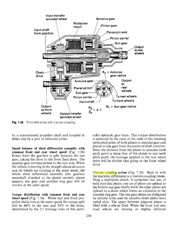
Input transfer sprocket wheel
Input shaft / from gearbox
Multiplate clutch
Annulus gear
on gear
Pinion pin axis
jPinion carrier Sun gear
Output to rear wheels
C h a i n m [ [ ~ ~ ~ ~ ~ Ra = Annulus drive ~ gearradius
Annulus gear ...... / ~ Output
~ ~ Planet p i n i o n ~ tr°ar Sungear , ~ ~ ~ wheels
Pinion carrier - - j ~ \ To rearwheels \ Input shaft / To front wheels
Output \ Ra Rs = Sun gear radius to front \ - 2"1 wheels Output transfer Rs
sprocket wheel Fig. 7.36 Third differential with viscous coupl ing
by a conventional propellor shaft and coupled at either end by a pair of universal joints.
Speed balance of third differential assembly with common front and rear wheel speed (Fig. 7.36) Power from the gearbox is split between the sun gear, taking the drive to the front final drive. The annulus gear conveys power to the rear axle. When the vehicle is moving in the straight ahead direction and all wheels are rotating at the same speed, the whole third differential assembly (the gearbox mainshaft attached to the planet carrier), planet pinions, sun gear and annulus ring gear will all revolve at the same speed.
Torque distribution with common front and rear wheel speed (Fig. 7.36) While rear and front pro- pellor shafts turn at the same speed, the torque split will be 66% to the rear and 34% to the front, determined by the 2:1 leverage ratio of this parti-
258
cular epicyclic gear train. This torque distribution is achieved by the ratio of the radii of the meshing teeth pitch point of both planet to annulus gear and planet to sun gear from the centre of shaft rotation. Since the distance from the planet to annulus teeth pitch point is twice that of the planet to sun teeth pitch point, the leverage applied to the rear wheel drive will be double that going to the front wheel drive.
Viscous coupling action (Fig. 7.36) Built in with the epicyclic differential is a viscous coupling resem- bling a multiplate clutch. It comprises two sets of mild steel disc plates; one set of plates are splined to the hollow sun gear shafts while the other plates are splined to a drum which forms an extension to the annulus ring gear. The sun gear plates are disfigured by circular holes and the annulus drum plates have radial slots. The space between adjacent plates is filled with a silicon fluid. When the front and rear road wheels are moving at slightly different
zhe huang
Highlight
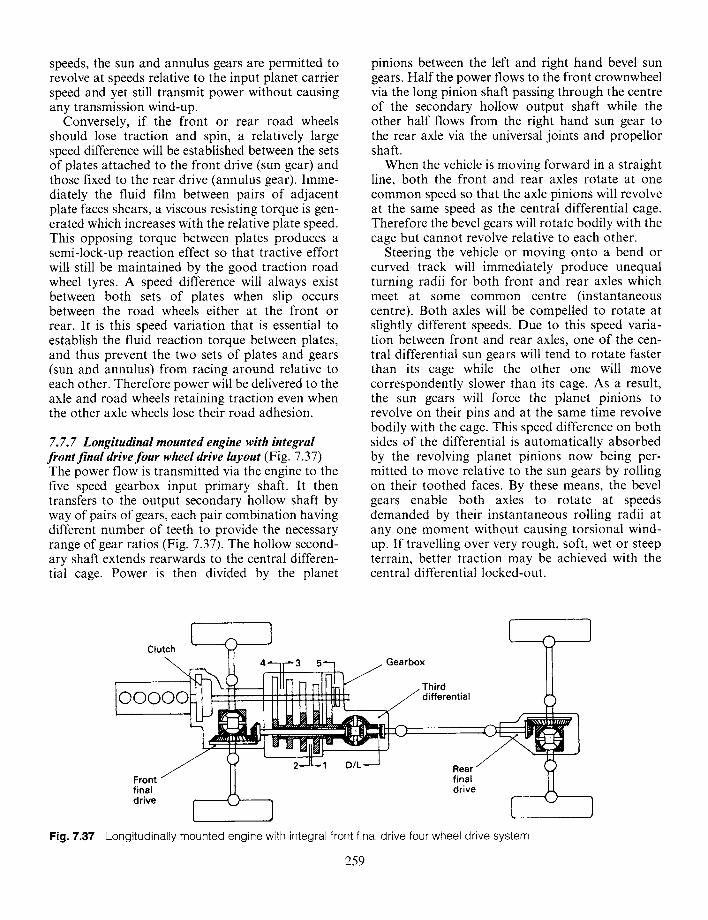
speeds, the sun and annulus gears are permitted to revolve at speeds relative to the input planet cartier speed and yet still transmit power without causing any transmission wind-up.
Conversely, if the front or rear road wheels should lose traction and spin, a relatively large speed difference will be established between the sets of plates attached to the front drive (sun gear) and those fixed to the rear drive (annulus gear). Imme- diately the fluid film between pairs of adjacent plate faces shears, a viscous resisting torque is gen- erated which increases with the relative plate speed. This opposing torque between plates produces a semi-lock-up reaction effect so that tractive effort will still be maintained by the good traction road wheel tyres. A speed difference will always exist between both sets of plates when slip occurs between the road wheels either at the front or rear. It is this speed variation that is essential to establish the fluid reaction torque between plates, and thus prevent the two sets of plates and gears (sun and annulus) from racing around relative to each other. Therefore power will be delivered to the axle and road wheels retaining traction even when the other axle wheels lose their road adhesion.
7. 7. 7 Longitudinal mounted engine with integral front final drive four wheel drive layout (Fig. 7.37) The power flow is transmitted via the engine to the five speed gearbox input primary shaft. It then transfers to the output secondary hollow shaft by way of pairs of gears, each pair combination having different number of teeth to provide the necessary range of gear ratios (Fig. 7.37). The hollow second- ary shaft extends rearwards to the central differen- tial cage. Power is then divided by the planet
pinions between the left and right hand bevel sun gears. Half the power flows to the front crownwheel via the long pinion shaft passing through the centre of the secondary hollow output shaft while the other half flows from the right hand sun gear to the rear axle via the universal joints and propellor shaft.
When the vehicle is moving forward in a straight line, both the front and rear axles rotate at one common speed so that the axle pinions will revolve at the same speed as the central differential cage. Therefore the bevel gears will rotate bodily with the cage but cannot revolve relative to each other.
Steering the vehicle or moving onto a bend or curved track will immediately produce unequal turning radii for both front and rear axles which meet at some common centre (instantaneous centre). Both axles will be compelled to rotate at slightly different speeds. Due to this speed varia- tion between front and rear axles, one of the cen- tral differential sun gears will tend to rotate faster than its cage while the other one will move correspondently slower than its cage. As a result, the sun gears will force the planet pinions to revolve on their pins and at the same time revolve bodily with the cage. This speed difference on both sides of the differential is automatically absorbed by the revolving planet pinions now being per- mitted to move relative to the sun gears by rolling on their toothed faces. By these means, the bevel gears enable both axles to rotate at speeds demanded by their instantaneous rolling radii at any one moment without causing torsional wind- up. If travelling over very rough, soft, wet or steep terrain, better traction may be achieved with the central differential locked-out.
Fig. 7.37
[ Clutch
ooo
. t
Front " final drive [
]
, I [ ~ l [ r ] J-] [- -Irl] ~ / G e a r b ° x Third
.~= J . ~ differential
i __ 2"-IL" 1 D/L"--J Rear
final
___J
{
drive _ _
..] [ ] Longitudinally mounted engine with integral front final drive four wheel drive system
259
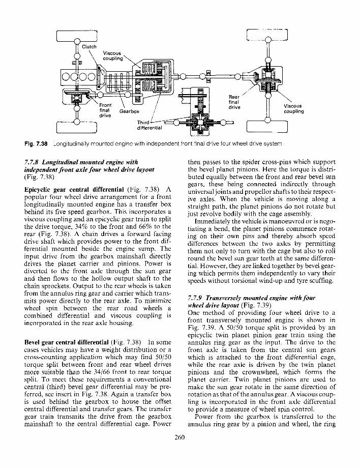
Fig. 7.38
[ ] [ ~) Clutch ~L, \ Viscous
\ coupling~ . ~ -.
lo roo Hn [ - ~ ~ l ~ . . . ~ l =J~J ~ ~ '1 Rear
final Gearbox / drive T h i r d ~ ~ - '
[- ] differential - ~ -- [
t Viscous coupling
Longitudinally mounted engine with independent front final drive four wheel drive system
7. 7.8 Longitudinal mounted engine with independent front axle four wheel drive layout (Fig. 7.38)
Epicyclic gear central differential (Fig. 7.38) A popular four wheel drive arrangement for a front longitudinally mounted engine has a transfer box behind its five speed gearbox. This incorporates a viscous coupling and an epicyclic gear train to split the drive torque, 34% to the front and 66% to the rear (Fig. 7.38). A chain drives a forward facing drive shaft which provides power to the front dif- ferential mounted beside the engine sump. The input drive from the gearbox mainshaft directly drives the planet carrier and pinions. Power is diverted to the front axle through the sun gear and then flows to the hollow output shaft to the chain sprockets. Output to the rear wheels is taken from the annulus ring gear and carrier which trans- mits power directly to the rear axle. To minimize wheel spin between the rear road wheels a combined differential and viscous coupling is incorporated in the rear axle housing.
Bevel gear central differential (Fig. 7.38) In some cases vehicles may have a weight distribution or a cross-counting application which may find 50/50 torque split between front and rear wheel drives more suitable than the 34/66 front to rear torque split. To meet these requirements a conventional central (third) bevel gear differential may be pre- ferred, see insert in Fig. 7.38. Again a transfer box is used behind the gearbox to house the offset central differential and transfer gears. The transfer gear train transmits the drive from the gearbox mainshaft to the central differential cage. Power
260
then passes to the spider cross-pins which support the bevel planet pinions. Here the torque is distri- buted equally between the front and rear bevel sun gears, these being connected indirectly through universal joints and propellor shafts to their respect- ive axles. When the vehicle is moving along a straight path, the planet pinions do not rotate but just revolve bodily with the cage assembly.
Immediately the vehicle is manoeuvred or is nego- tiating a bend, the planet pinions commence rotat- ing on their own pins and thereby absorb speed differences between the two axles by permitting them not only to turn with the cage but also to roll round the bevel sun gear teeth at the same differen- tial. However, they are linked together by bevel gear- ing which permits them independently to vary their speeds without torsional wind-up and tyre scuffing.
7.7.9 Transversely mounted engine with four wheel drive layout (Fig. 7.39) One method of providing four wheel drive to a front transversely mounted engine is shown in Fig. 7.39. A 50/50 torque split is provided by an epicyclic twin planet pinion gear train using the annulus ring gear as the input. The drive to the front axle is taken from the central sun gears which is attached to the front differential cage, while the rear axle is driven by the twin planet pinions and the crownwheel, which forms the planet carrier. Twin planet pinions are used to make the sun gear rotate in the same direction of rotation as that of the annulus gear. A viscous coup- ling is incorporated in the front axle differential to provide a measure of wheel spin control.
Power from the gearbox is transferred to the annulus ring gear by a pinion and wheel, the ring
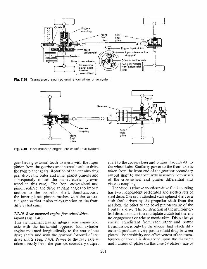
Ii i ] tch _ v,scous
, .'HI , ~ coupling ] ~ ~ j Front R e a r - . . _ ~ ]
final final drive drive
" ~ ' ~ ~ ~ ' ~ - T h l r d ~ ~ Engine input pinion [ ii~ [ O differential ~ - ~ \ .- Input drive annulus
i ]__ Gearbox r / / / . . . /~ "~ ring gear
. U;J | | Drive to rear wheels ~ k ~ ) i s~iV; ~° I rfT:;~t7 sIs ~1~ _ [" Twin pinion ]
r "-" 1 / planet gears / \ ~ / / front differential [ [ • J | fixed to | ~ ~ " L cage t
L crownwheel J Fig. 7.39 Transversely mounted engine four wheel drive system
l l v,scous
coupling t
~'J ] drive
Gearbox__ I ~ Clitc !
._~.._ , ~ JH HHHI~L~ J _ ' K
I-'k~=~[2 ) ~'Lj Rear [ ' J ~ ~ S = [ i]j (~ -]
:a'o J
Fig. 7.40 Rear mounted engine four wheel drive system
gear having external teeth to mesh with the input pinion from the gearbox and internal teeth to drive the twin planet gears. Rotation of the annulus ring gear drives the outer and inner planet pinions and subsequently rotates the planet carrier (crown- wheel in this case). The front crownwheel and pinion redirect the drive at right angles to impart motion to the propellor shaft. Simultaneously the inner planet pinion meshes with the central sun gear so that it also relays motion to the front differential cage.
7. 7.10 Rear mounted engine four wheel drive layout (Fig. 7.40) This arrangement has an integral rear engine and axle with the horizontal opposed four cylinder engine mounted longitudinally to the rear of the drive shafts and with the gearbox forward of the drive shafts (Fig. 7.40). Power to the rear axle is taken directly from the gearbox secondary output
261
shaft to the crownwheel and pinion through 90 ° to the wheel hubs. Similarly power to the front axle is taken from the front end of the gearbox secondary output shaft to the front axle assembly comprised of the crownwheel and pinion differential and viscous coupling.
The viscous relative speed-sensitive fluid coupling has two independent perforated and slotted sets of steel discs. One set is attached via a splined shaft to a stub shaft driven by the propellor shaft from the gearbox, the other to the bevel pinion shank of the front final drive. The construction of the multi-inter- leaf discs is similar to a multiplate clutch but there is no engagement or release mechanism. Discs always remain equidistant from each other and power transmission is only by the silicon fluid which stiff- ens and produces a very positive fluid drag between plates. The sensitivity and effectiveness of the trans- ference of torque is dependent upon the diameter and number of plates (in this case 59 plates), size of
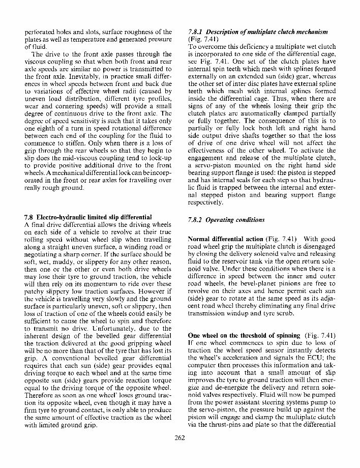
perforated holes and slots, surface roughness of the plates as well as temperature and generated pressure of fluid.
The drive to the front axle passes through the viscous coupling so that when both front and rear axle speeds are similar no power is transmitted to the front axle. Inevitably, in practice small differ- ences in wheel speeds between front and back due to variations of effective wheel radii (caused by uneven load distribution, different tyre profiles, wear and cornering speeds) will provide a small degree of continuous drive to the front axle. The degree of speed sensitivity is such that it takes only one eighth of a turn in speed rotational difference between each end of the coupling for the fluid to commence to stiffen. Only when there is a loss of grip through the rear wheels so that they begin to slip does the mid-viscous coupling tend to lock-up to provide positive additional drive to the front wheels. A mechanical differential lock can be incorp- orated in the front or rear axles for travelling over really rough ground.
7.8.1 Description of multiplate clutch mechanism (Fig. 7.41) To overcome this deficiency a multiplate wet clutch is incorporated to one side of the differential cage, see Fig. 7.41. One set of the clutch plates have internal spin teeth which mesh with splines formed externally on an extended sun (side) gear, whereas the other set of inter disc plates have external spline teeth which mesh with internal splines formed inside the differential cage. Thus, when there are signs of any of the wheels losing their grip the clutch plates are automatically clamped partially or fully together. The consequence of this is to partially or fully lock both left and right hand side output drive shafts together so that the loss of drive of one drive wheel will not affect the effectiveness of the other wheel. To activate the engagement and release of the multiplate clutch, a servo-piston mounted on the right hand side bearing support flange is used: the piston is stepped and has internal seals for each step so that hydrau- lic fluid is trapped between the internal and exter- nal stepped piston and bearing support flange respectively.
7.8 Electro-hydraulic limited slip differential A final drive differential allows the driving wheels on each side of a vehicle to revolve at their true rolling speed without wheel slip when travelling along a straight uneven surface, a winding road or negotiating a sharp corner. If the surface should be soft, wet, muddy, or slippery for any other reason, then one or the other or even both drive wheels may lose their tyre to ground traction, the vehicle will then rely on its momentum to ride over these patchy slippery low traction surfaces. However if the vehicle is travelling very slowly and the ground surface is particularly uneven, soft or slippery, then loss of traction of one of the wheels could easily be sufficient to cause the wheel to spin and therefore to transmit no drive. Unfortunately, due to the inherent design of the bevelled gear differential the traction delivered at the good gripping wheel will be no more than that of the tyre that has lost its grip. A conventional bevelled gear differential requires that each sun (side) gear provides equal driving torque to each wheel and at the same time opposite sun (side) gears provide reaction torque equal to the driving torque of the opposite wheel. Therefore as soon as one wheel' loses ground trac- tion its opposite wheel, even though it may have a firm tyre to ground contact, is only able to produce the same amount of effective traction as the wheel with limited ground grip.
7.8.2 Operating conditions
Normal differential action (Fig. 7.41) With good road wheel grip the multiplate clutch is disengaged by closing the delivery solenoid valve and releasing fluid to the reservoir tank via the open return sole- noid valve. Under these conditions when there is a difference in speed between the inner and outer road wheels, the bevel-planet pinions are free to revolve on their axes and hence permit each sun (side) gear to rotate at the same speed as its adja- cent road wheel thereby eliminating any final drive transmission windup and tyre scrub.
One wheel on the threshold of spinning (Fig. 7.41) If one wheel commences to spin due to loss of traction the wheel speed sensor instantly detects the wheel's acceleration and signals the ECU; the computer then processes this information and tak- ing into account that a small amount of slip improves the tyre to ground traction will then ener- gize and de-energize the delivery and return sole- noid valves respectively. Fluid will now be pumped from the power assistant steering systems pump to the servo-piston, the pressure build up against the piston will engage and clamp the multiplate clutch via the thrust-pins and plate so that the differential
262
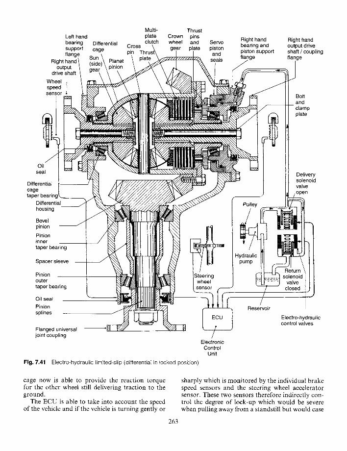
Left hand bearing support flange
Right hand output
drive shaft
Wheel i speed sensor
Differential cage
Sun )~ (side Planet . . . . pinion
oil seal
Differential m cage taper bearing
Differential housing
Bevel pinion
Pinion inner taper bearing
Spacer sleeve
Pinion outer taper bearing
Oil seal Pinion splines
Flanged universal joint coupling
Fig. 7.41
Cross. pin
Multi- plate clutch
Crown wheel
Thrust pins and plate
Servo piston and
seals
Right hand bearing and piston support flange
Right hand output drive shaft / coupling flange
~ I i lllll
Steering wheel ensor { - - - -
/ Electronic
Control Unit
Electro-hydraulic limited-slip (differential in locked position)
Pulley
Hydraulic pump
Bolt and clamp plate
Delivery solenoid valve ooen
Return solenoid
valve closed
Reservoir
Electro-hydraulic control valves
cage now is able to provide the reaction torque for the other wheel still delivering traction to the ground.
The ECU is able to take into account the speed of the vehicle and if the vehicle is turning gently or
263
sharply which is monitored by the individual brake speed sensors and the steering wheel accelerator sensor. These two sensors therefore indirectly con- trol the degree of lock-up which would be severe when pulling away from a standstill but would ease
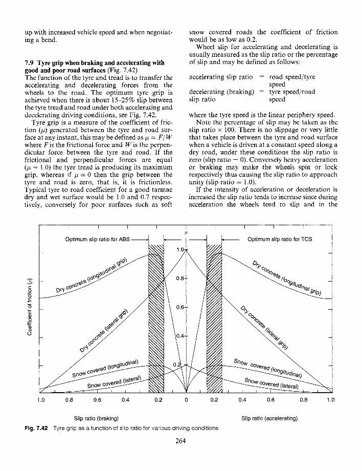
up with increased vehicle speed and when negotiat- ing a bend.
7.9 Tyre grip when braking and accelerating with good and poor road surfaces (Fig. 7.42) The function of the tyre and tread is to transfer the accelerating and decelerating forces from the wheels to the road. The optimum tyre grip is achieved when there is about 15-25% slip between the tyre tread and road under both accelerating and decelerating driving conditions, see Fig. 7.42.
Tyre grip is a measure of the coefficient of fric- tion (#) generated between the tyre and road sur- face at any instant, this may be defined as # - F~ W where F is the frictional force and W is the perpen- dicular force between the tyre and road. If the frictional and perpendicular forces are equal (# = 1.0) the tyre tread is producing its maximum grip, whereas if # = 0 then the grip between the tyre and road is zero, that is, it is frictionless. Typical tyre to road coefficient for a good tarmac dry and wet surface would be 1.0 and 0.7 respec- tively, conversely for poor surfaces such as soft
snow covered roads the coefficient of friction would be as low as 0.2.
Wheel slip for accelerating and decelerating is usually measured as the slip ratio or the percentage of slip and may be defined as follows:
accelerating slip ratio = road speed/tyre speed
decelerating (braking) = tyre speed/road slip ratio speed
where the tyre speed is the linear periphery speed. Note the percentage of slip may be taken as the
slip ratio x 100. There is no slippage or very little that takes place between the tyre and road surface when a vehicle is driven at a constant speed along a dry road, under these conditions the slip ratio is zero (slip ratio = 0). Conversely heavy acceleration or braking may make the wheels spin or lock respectively thus causing the slip ratio to approach unity (slip ratio = 1.0).
If the intensity of acceleration or deceleration is increased the slip ratio tends to increase since during acceleration the wheels tend to slip and in the
¢-
0 . m c.) . m
0 ¢.,. (D
0 : t : :
0 o
T 1 [ T T
Optimum slip ratio for ABS
Sf~°~N - _
Snow
1.0 0.8 0.6 0.4 0.2 0 0.2
f [ I I
Snow
Optimum slip ratio for TCS
0.4 0.6 0.8 1.0
Slip ratio (braking)
Fig. 7.42 Tyre grip as a function of slip ratio for various driving conditions
264
Slip ratio (accelerating)
extreme spin, whereas during deceleration (braking) the wheels tend to move slower than the vehicle speed and under very heavy braking will lock, that is stop rotating and just slide along the surface. When considering the relationship between tyre slip and grip it should be observed that the tyre grip measurements are in two forms, longitudinal (length- ways) forces and lateral (sideways) forces, see Fig. 7.42. In both acceleration and deceleration in the longitudinal direction mode a tyre tends to produce its maximum grip (high #) with a slip ratio of about 0.2 and as the slip ratio decreases towards zero, the tyre grip falls sharply; however, if the slip ratio increases beyond the optimum slip ratio of 0.2 the tyre grip will tend to decrease but at a much slower rate. With lateral direction grip in terms of sideways force coefficient of friction, the value of # (grip) is much lower than for the forward rolling frictional grip and the maximum grip (high #) is now produced with zero tyre slip. Traction control systems (TCS) respond to wheel acceleration caused by a wheel spinning as its tyre loses its grip with the road sur- face, as opposed to antilock braking systems (ABS) which respond to wheel deceleration caused by a wheel braking and preventing the wheel from turn- ing and in the limit making it completely lock.
7.10 Traction control system With a conventional final drive differential the torque output from each driving wheel is always equal. Thus if one wheel is driven over a slippery patch, that wheel will tend to spin and its adjacent sun (side) gear will not now be able to provide the reaction torque for the other (opposite) sun (side) gear and driving road wheel. Accordingly, the out- put torque on the other wheel which still has a good tyre to surface grip will be no more than that of the slipping wheel and it doesn't matter how much the driver accelerates to attempt to regain traction, there still will be insufficient reaction torque on the spinning side of the differential for the good wheel to propel the vehicle forward.
One method which may be used to overcome this loss of traction when one wheel loses its road grip, is to simply apply the wheel brake of the wheel show- ing signs of spinning so that a positive reaction torque is provided in the differential; this counter- acts the delivery to the good wheel of the half share of the driving torque being supplied by the com- bined engine and transmission system in terms of tractive effort between the tyre and ground.
To achieve this traction control an electronic con- trol unit (ECU) is used which receives signals from
265
individual wheel speed sensors, and as soon as one of the driving wheels tends to accelerate (spin due to loss of tyre to ground traction), the sensor's gener- ated voltage change is processed by the ECU com- puter, and subsequently current is directed to the relevant traction solenoid valve unit so that hydrau- lic brake pressure is transmitted to the brake of the wheel about to lose its traction. As soon as the braked wheel's speed has been reduced to a desirable level, then the ECU signals the traction solenoid valve unit to release the relevant wheel brake.
7.10.1 Description of system (Fig. 7.43) This traction control system consists of: an electric motor driven hydraulic pump which is able to gen- erate brake pressure independently to the foot brake master cylinder and a pressure storage accumulator; a traction boost unit which comprises a cylinder housing, piston and poppet valve, the purpose of which is to relay hydraulic pressure to the appropri- ate wheel brake caliper and at the same time main- tain the traction boost unit circuit fluid separate from the foot brake master cylinder fluid system; a pair of traction solenoid valve units each having an outlet and return valve regulates the cut-in and -out of the traction control; an electronic control unit (ECU) is provided and individual wheel speed sen- sors which monitor the acceleration of both driven and non-driving wheels. Should the speed of either of the driven wheels exceed the mean wheel speed of the non-driven wheels by more than about 20%, then the ECU will automatically apply the appro- priate wheel brake via the traction solenoid valves and traction boost device.
7.10.2 Operating conditions
Foot brake applied (Fig. 7.43(a)) With the foot pedal released brake fluid is able to flow freely between the master cylinder and both brake cali- pers via the open traction boost unit. The boost piston will be in its outer-most position thereby holding the poppet valve in its fully open position. When the foot pedal is pushed down, brake fluid pressure will be transmitted though the fluid via the traction boost poppet valve to both of the wheel calipers thus causing the brakes to be applied.
Traction control system applied (off-side slipping wheel braked) (Fig. 7.43(b)) When one of the driving wheels begins to spin (off-side wheel in this example) the adjacent speed sensor voltage change signals the ECU, immediately it computes
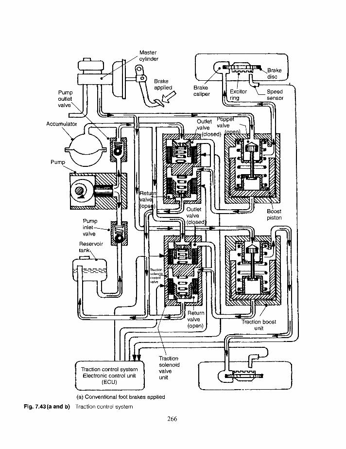
Pump outlet
Master cylinder
Brake applied Brake
caliper Excitor ring
Brake disc
Speed sensor
Accumulator
Pump
Pump inlet ~ - - ~ o valve
Reservoir
I
Outlet valve valve
piston
(open) Traction boost
unit
Traction control system Electronic control unit
(ECU)
Traction solenoid valve unit
(a) Conventional foot brakes applied
Fig. 7.43(a and b) Traction control system
266
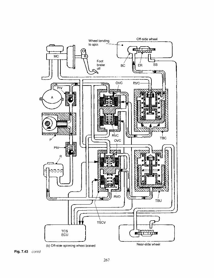
Wheel tending Off-side wheel ~ t o s p i n ~ ~ ~ ._
I I ii .... L I1 \\ broke - ~ ~[ ~-'~ ~,.~" BC [r~ER SS ~
OVC
Ill
I ~
TBU
Fig. 7.43 contd
TCS ECU
(b) Off-side spinning wheel braked
TSCV
Near-side wheel
2 6 7
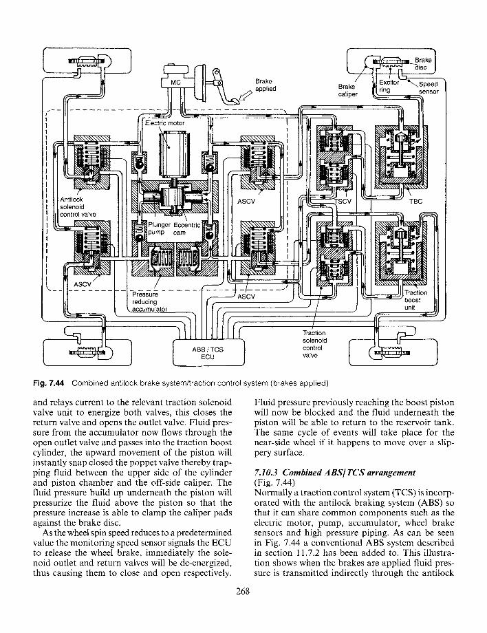
Electric motor
Brake ~ applied Brake
caliper ring
.Speed sensor
Antilock solenoid control valve
Plunger Eccentric pump cam
ASCV TBC
ASCV
Pressure reducing accumulator
ASCV
unit
Traction solenoid control
ECU I valve
Fig. 7.44 Combined antilock brake system/traction control system (brakes applied)
and relays current to the relevant traction solenoid valve unit to energize both valves, this closes the return valve and opens the outlet valve. Fluid pres- sure from the accumulator now flows through the open outlet valve and passes into the traction boost cylinder, the upward movement of the piston will instantly snap closed the poppet valve thereby trap- ping fluid between the upper side of the cylinder and piston chamber and the off-side caliper. The fluid pressure build up underneath the piston will pressurize the fluid above the piston so that the pressure increase is able to clamp the caliper pads against the brake disc.
As the wheel spin speed reduces to a predetermined value the monitoring speed sensor signals the ECU to release the wheel brake, immediately the sole- noid outlet and return valves will be de-energized, thus causing them to close and open respectively.
Fluid pressure previously reaching the boost piston will now be blocked and the fluid underneath the piston will be able to return to the reservoir tank. The same cycle of events will take place for the near-side wheel if it happens to move over a slip- pery surface.
7.10.3 Combined A BS] TCS arrangement (Fig. 7.44) Normally a traction control system (TCS) is incorp- orated with the antilock braking system (ABS) so that it can share common components such as the electric motor, pump, accumulator, wheel brake sensors and high pressure piping. As can be seen in Fig. 7.44 a conventional ABS system described in section 11.7.2 has been added to. This illustra- tion shows when the brakes are applied fluid pres- sure is transmitted indirectly through the antilock
268
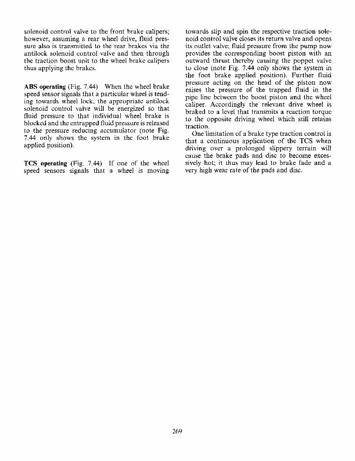
solenoid control valve to the front brake calipers; however, assuming a rear wheel drive, fluid pres- sure also is transmitted to the rear brakes via the antilock solenoid control valve and then through the traction boost unit to the wheel brake calipers thus applying the brakes.
ABS operating (Fig. 7.44) When the wheel brake speed sensor signals that a particular wheel is tend- ing towards wheel lock, the appropriate antilock solenoid control valve will be energized so that fluid pressure to that individual wheel brake is blocked and the entrapped fluid pressure is released to the pressure reducing accumulator (note Fig. 7.44 only shows the system in the foot brake applied position).
TCS operating (Fig. 7.44) If one of the wheel speed sensors signals that a wheel is moving
towards slip and spin the respective traction sole- noid control valve closes its return valve and opens its outlet valve; fluid pressure from the pump now provides the corresponding boost piston with an outward thrust thereby causing the poppet valve to close (note Fig. 7.44 only shows the system in the foot brake applied position). Further fluid pressure acting on the head of the piston now raises the pressure of the trapped fluid in the pipe line between the boost piston and the wheel caliper. Accordingly the relevant drive wheel is braked to a level that transmits a reaction torque to the opposite driving wheel which still retains traction.
One limitation of a brake type traction control is that a continuous application of the TCS when driving over a prolonged slippery terrain will cause the brake pads and disc to become exces- sively hot; it thus may lead to brake fade and a very high wear rate of the pads and disc.
269