
ADVANCED TECHNOLOGY CENTER WING BOX CONCEmUAL …
19
61-136 ADVANCED TECHNOLOGY CENTER WING BOX CONCEmUAL DESPGNICOST STUDY* R.S. Whitehead Northrop Corporation Hawthorne, California C.R. Foreman LTV Advanced Products Group Dallas, Texas Capt. K. Silva Wright Laboratories/FIBAC Dayton, Ohio ABSTRACT A conceptual design was developed by Northrop/LTV for an advanced C-130 Center Wing Box (CWB) which could meet the severe mission requirementsof the SOF C- 130aircraft. The goals for the advanced technology CWB relative to the current C-130H CWB were: (1) the same acquisition cost; (2) lower operating support costs; (3) equal or lower weight; (4) a 30,000 hour service life for the SOF mission; and (5) minimum impact on the current maintenance concept, Initially, the structural arrangement, weight, external and internal loads, fatigue spectrum, flutter envelope and design criteria for the SOF C-130 aircraft CWB were developed. An advanced materials assessment was then conducted to determine the suitability of advanced materials for a 1994 production availability and detailed trade studies were performed on candidate CWB concep- tual designs. Finally, a life-cycle cost analysis was performed on the advanced CWB. The study results demonstrated that a hybrid composite/metallic CWB could meet the severe SOF design requirements, reduce the CWB weight by 14percent, and was cost effective relative to an all metal beefed up C-130H CWB. * This work was performed under USAF Contract No. F33657-90-D-0027 Task Order 0005, September 1990 to April 1991.
Transcript of ADVANCED TECHNOLOGY CENTER WING BOX CONCEmUAL …

61-136 ADVANCED TECHNOLOGY CENTER WING BOX CONCEmUAL DESPGNICOST STUDY*
R.S. Whitehead Northrop Corporation Hawthorne, California
C.R. Foreman LTV Advanced Products Group
Dallas, Texas
Capt. K. Silva Wright Laboratories/FIBAC
Dayton, Ohio
ABSTRACT
A conceptual design was developed by Northrop/LTV for an advanced C-130 Center
Wing Box (CWB) which could meet the severe mission requirements of the SOF C- 130 aircraft. The
goals for the advanced technology CWB relative to the current C-130H CWB were: (1) the same
acquisition cost; (2) lower operating support costs; (3) equal or lower weight; (4) a 30,000 hour
service life for the SOF mission; and (5) minimum impact on the current maintenance concept,
Initially, the structural arrangement, weight, external and internal loads, fatigue spectrum, flutter
envelope and design criteria for the SOF C-130 aircraft CWB were developed. An advanced
materials assessment was then conducted to determine the suitability of advanced materials for a
1994 production availability and detailed trade studies were performed on candidate CWB concep-
tual designs. Finally, a life-cycle cost analysis was performed on the advanced CWB. The study
results demonstrated that a hybrid composite/metallic CWB could meet the severe SOF design
requirements, reduce the CWB weight by 14 percent, and was cost effective relative to an all metal
beefed up C-130H CWB.
* This work was performed under USAF Contract No. F33657-90-D-0027 Task Order 0005, September 1990 to April 1991.

INTRODUCTION The airframes of SOF C - 130 aircraft have approximately one-third the service life of a
C-130H airframe. In addition, the center wing box (CWB) structure, which is common to both the
C- 13013 and SOF CI: - 130, is the life iimiting portion of the airframe. The reduced service life of the
SOF C -130 airframe can be attributed to two primary factors, these are: a severe tactical flight
mission profile and high operational weight. As a consequence, the SOF C -130 CWB structure has
a fierce time compliance technical order (TCTO) maintenance burden, which generates high
operating and support costs. Several life extension alternatives exist for these airframes: (1) revised
mission scenarios; (2) increasedinspection frequency; (3) a beefed-up metal CWB; or (4) application
of advanced structures and materials technologies to a redesigned CWB. The purpose of this study
(Reference 1) was to explore the latter alternative. Specific objectives were to develop an advanced
technology SOF C - 130 CWB conceptual design and to determine its acquisition and operation and
support costs. The goals for the advanced technology CWB relative to the current C-130H CWB
were: (1) the same acquisitibn cost; (2) lower operating and support costs; (3) equal or lower weight;
(4) a 30,000 hour service life for the SOF mission; and (5) minimum impact on the current
maintenance concept.
C-130H CWB STRUCTURAL ARRANGEMENT An isometric view of the C-130H CWB structure is shown in Figure 1. The CWB
structure spans WS 220 left to WS 220 right, minus the leading edge structure forward of the front
beam and trailing edge structure aft of the rear beam. The box consists of upper and lower multi-piece
hat stiffened skins, front and rear beams (spars) and ten ribs. Bladder type fuel tanks are contained
between WS 61 and 178 left and right. The current design is all metal, mainly 7075-T73 aluminum
alloy.
The advanced design CWB has to maintain several structural interfaces. These are (1)
fuselage attachments at WS 20 ribs left and right to BL20 fuselage upper longerons, (2) fuselage
attachments at WS 61 left and right - lower skin to drag angle, front beam to fuselage post, and aft
beam to fuselage post, (3) the inboard engine truss mount left and right, (4) the outer wing attachment
through upper and lower rainbow fittings, corner fittings, and spar web splices at WS 220 left and
right, and (5) the leading edge assembly attachment to the front beam and trailing edge attachment
at the rear beam. System interfaces are: (1) fuel systems that penetrate the front beam and ribs at
WS 178, (2) electrical controls (engine and flight) and ECS along the front beam outside of the box,
and (3) multiple penetrations in the center dry bay area.

Figure 1. C- 130 CWB Structural Arrangement.
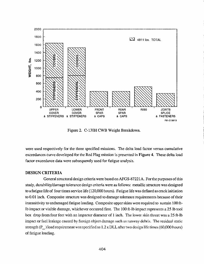
A weight breakdown of the C-130H CWB is presented in Figure 2. Total weight is 48 11
lb, where the upper andlower wing skins represent approximately two-thirds of this weight. Previous
studies have shown that a metal "beef-up" of approximately 1000 lb is required to provide a durable
CWB for the SOF C -130 mission profile.
The primary external loads on the C- 130H CWB were derived from flight maneuver, gust
loads, and groundconditions. Six critical conditions constitute the comer points of the load envelope
for the middle of the CWB at WS 95. These load envelopes are shown in Figure 3. These six load
conditions were selected for internal loads development for the baseline C-130H CWB and included
maximum and minimum bending moments, shears and torsions, and combinations thereof. The
loads in Figure 3 were increased by 20% to account for the more severe SOF C mission. The advanced
CWB was designed to these increased loads.
The SOF C - 130 CWB fatigue load spectrum was not available for this conceptual design
study program. An approximate SOF G -130 CTi;VB fatigue specbvm was developed with Air Force
approval. The mission mix was specified as 20 percent proficiency training, 30 percent short range
logistics, and 50 percent combat training. Exceedance data for tactical training, ferry and Red Flag
UPPER COVER
& STIFFENERS
LOWER COVER
& STIFFENERS
FRONT SPAR
& CAPS
481 1 Ibs. TOTAL
I
REAR SPAR
& CAPS
RIBS JOINTS SPLICE
& FASTENERS F91-C130113
Figure 2. C- 130H CWB Weight Breakdown.
were used respectively for the three specified missions. The delta load factor versus cumulative
exceedances curve developed for the Red Flag mission is presented in Figure 4. These delta load
factor exceedance data were subsequently used for fatigue analysis.
DESIGN CRITERIA General structural design criteria were based on AFGS-87221A. For the purposes of this
study, durabilityldamage tolerance design criteria were as follows: metallic structure was designed
to a fatigue life of four times service life (120,000 hours). Fatigue life was defined as crack initiation
to 0.01 inch. Composite structure was designed to damage tolerance requirements because of their
insensitivity to undamaged fatigue loading. Composite upper skins were required to sustain '100 ft-
lb impact or visible damage, whichever occurred first. The 100 ft-lb impact represents a 25 lb tool
box drop from four feet with an impactor diameter of 1 inch. The lower skin threat was a 25 ft-lb
impact or fuel leakage caused by foreign object damage such as runway debris. The residual static
strength (PXX) load requirement was specified as f .2 x BEE after two design life times (60,000 hours)
of fatigue loading.

Figure 3. C-130H External Loads Envelope - Wing Station Limit Loads.

1 .oo 2.00 DELTA LOAD FACTOR (AN 3
Figure 4. C-130 Red Flag Delta Load Factor Exceedances.
Design allowables for mature metallic alloys were taken from MIL-HDBK-5. Advanced
metallic alloy allowables were derived from in-house data. Two classes of composite materials were
utilized in the study: two first generation epoxies, AS413501-6 and AS413502, and two second
generation toughened thermosets with an intermediate modulus fiber; they were IM7/8552 andIM71
5250-4. These materials were selected after a comprehensive advanced materials assessment which
is documented in Reference 1. Lamina and laminate strength design allowables for unidirectional
tape are given below:
Lamina Allowables
Tension Modulus E, = 18.7 Msi AS413501-6 or 3502
Compression Modulus E, = 17.6 Msi
i Tension Modulus E, = 22.6 Msi IM918552 or 5250-4
Compression Modulus E, = 20.2 Msi

Laminate Allowables
TENSION- COMPRESSION= 5,000 pin/in &ALLOW - &ALLOW
Interlaminar Tension Strength
TENSION = 2400 psi GALLOW
The laminate strength allowables (for all materials) of 5000 pidin are based on a 0.25
inch fastener hole and account for an operating environment of -67OF to 180°F with end-of-lifetime
moisture content. Test data indicate a potential for laminate strain allowables in excess of 5000 pin/
in. However, the laminate strain allowable was limited to 5000 pidin for three reasons: (1) bolted
repair capability; (2) minimization of bolt bearing by-pass effects; and (3) ballistic damage tolerance.
The interlaminar tension strength allowable is derived from test data on low-to-medium toughness
thermoset systems such as ASl3501-6 and AS415250-3.
The durability design allowable is driven by control of hole wear in highly loaded holes.
This is achieved by limiting bearing stresses such that
'IELD = DESIGN LIMIT LOAD = 70 ksi ALLOW
Damage tolerance allowables at design ultimate load ranged from 3 125 pidin to 5000
pidin because of their dependency on impact threat severity, material toughness, and laminate
thickness.
TRADE STUDIES Figure 5 surnrnarizes the overall trade study approach, which was conducted in three
phases. In Phase I, the team is selected, a kick-off meeting is convened, and the study criteria are
established based on customer needs which are translated into product and process design require-
ments. At the end of Phase I, trade study initiation forms are completed for each task.
In Phase 11, team brainstorming sessions generate design concepts from which candidate
concepts are downselected for further evaluation. The brainstorming sessions develop as many
viable concepts as possible in order to increase the chances of identifying and selecting the best
approach. Preliminary downselection of the candidate concepts is based on the Pugh method of
concept evalua~on.

"Brainstorming"
r SELECTTEAM c BRAINSTORMING e PRODUCT DESIGN LAYOUT
e CONDUCT KICK-OFF MEETING e GENERATE CONCEPTS e PROCESS DESIGN LAYOUT
e ESTABLISH CRITERIA e EVALUATE CONCEPTS e PRODUCTJPROCESS REVIEW
e COMPLETE TRADE STUDY e DOWNSELECT CONCEPTS e WEIGHT ANALYSIS INITIATION FORMS FOR DETAILED STUDY
e COST ANALYSIS
e RANKING MATRIX
e SELECTION
e STUDY REPORT F91ClW19
Figure 5. Overal Trade Study Approach.
The Pugh method results in a manageable number of relevant design concepts that can
be evaluated in greater detail. The Phase 111 approach developed to accomplish this evaluation is a
tailored approach which uses traditional trade study measures of merit and weighting factors. Also,
elements and techniques common to the application of Quality Function Deployment and "Forced
Decision Making" have been incorporated into the methodology. Included among these elements
is a strong emphasis on team effort, the physical format, and the "What-How" approach to evaluating
the relationships between the concepts and the selection criteria. Forced Decision Making requires
each concept to be evaluated not only with respect to how well it satisfies the design requirements,
but also how well it satisfies these requirements with respect to the other concepts. To adequately
assess the concepts in Phase 111, a thorough understanding of each of the downselected concepts is
required. It is essential for the Pugh preliminary downselection process to eliminate as many
concepts as possible to reduce the effort required in Phase 111.
Trade studies were conducted on the CWB wing skins, spars, ribs, and rainbow fitting.
The wing skin trade study is discussed because it had the most impact on the final conceptual design.
Wing Skin Trade Studies
The objective of this trade study was to compare design configurations and manufactur-
ing methods for fabricating the stiffened upper and lower wing skins for the center wing box of the

(2- 130. SEn stiffener configurations and potential tmling and fabrication approaches were analyzed
md evduatd to select the prefened concept for full-scale development.
Five candidak skin concepts emerged from the Phase 11 brainstoming for p re l i~nary
concept evaluation using the Pugh method. The first concept was an advanced metallic skin. The
other four were composite wing skin design concepts which featured different stiffener configura-
tions for integrally stiffened, monolithic one-piece composite skins. The stiffener cross-sections
included blades, hats, "I-beams," and "J"s. Figure 6 shows the results of the Pugh analysis of these
five concepts. The advanced metal concept was rated unsatisfactory for weight because it could not
meet the weight target and satisfy the durability requirements. It was concluded that the excellent
Figure 6. Phase DI Pugh Preliminary Concept Evaluation for Wing Skin Trade Studies.

durability characteristics of composite wing skins were necessary to achieve the C m structural
weight goal. Relirzlinary downsel~tion elifninatd the ""I[kam" and ""Jkonfigurations (Concepts
4 and 5), primarily based on the greater manufacturing risk and higher cost of these configurations
compared to the blades and hats (Concepts 2 and 3). Fuel sealing requirements were also considered
in this preliminary evaluation. The assessment of manufacturing risk and cost was based on the
complexity of the stiffener shape, the number of details comprising the stiffener, the tooling
requirements, and the manufacturing experience of Northrop and LTV. The Pugh evaluation in
Figure 6 shows that blade and hat stiffeners were preferred to "I-beam" and "J" stiffeners, because
they had major advantages in the areas of fuel sealing, cost, risk and repairability. Therefore, the
hat and blade stiffened composite wing skin concepts were selected as the candidates for the more
detailed Phase III evaluation prior to downselecting to a preferred approach. OML and IML tooling
concepts were considered for both stiffening configurations; Figure 7 shows the four candidate
concepts. The detailed downselection focused on manufacturing risk issues - tooling, fabrication,
and assembly - and on achieving an integral fuel tank.
A key issue in the selection of the wing skin stiffening concept was continuous versus
discontinuous stiffening elements. Fuel sealing at the fuel closeout riblwing skin-stiffener intersec-
tion was acritical requirement in the integral fuel tank design. Successful, reliable fuel sealing at this
intersection is dependent on many factors, including the rib and stiffener configurations.
The continuous stiffening approach uses wing skin stiffeners uninterrupted at the fuel
closeout rib intersections. The ribcaps are joggled around the stiffeners or are relieved at the stiffener
intersections and separate fittings are used to achieve the fuel seal. In the discontinuous stiffener
approach, the stiffeners are interrupted at the rib intersections and a flat rib cap assembles to a flat
land areaon the wing skin, creating the fuel seal. It is clear from a structural load carrying perspective,
that the continuous stiffener approach is preferred. The severe loading conditions and the proximity
of the outboard fuel closeout ribs to the wing attach fitting do not favor the discontinuous stiffener
concept. The ability to transition loads from the wing skin stiffeners around (into the skin) or through
(using a separate fitting) the fuel closeout rib was a critical factor in the wing skin stiffening concept
decision making process. A discontinuous wing skin stiffening approach is preferred when
considering the fuel sealing requirements at the rib caplwing skin stiffener intersections. In this
approach, the fuel seal can be accomplished without the need for a complex rib cap configuration or
subsequent assembly operations.
Continuous stiffening was determined to be the preferred approach for satisfying the
wing skin and the integral fuel tank requirements. Using concurrent engineering in the development

HATS
Concept A1
Concept A2
BLADES
I BLADE STIFFENERS - IML TOOL
Concept B1
Composite Strongback
Silicone rubber facesheet
Concept: B2 FQi Clrn3A
Figure 7. Phase III Candidate Wing Skin Concepts.
prmess, and applying the trade study methodology, it was determind that the design and manufac-
t u h g complexity resulting from stiffener discontinuity would outweigh the potential fuel sealing
benefits. As a result, the wing skin stiffener configuration candidates shown in Figure 7 assumed
continuous stiffeners in the design.
Recent successful IR&D activities for developing integral fuel tank designs using
cocured hat stiffened skins and the IML tooling approach (Concept A1 in Figure 7) have identified
and addressed many of the manufacturing risk issues. As a result of the IRBrD development,
Northrop/LTV have a high degree of confidence in this approach. IML tooling is preferred as a means
of controlling the assembly surfaces to support the incorporation of an integral fuel tank into the wing
box design. Concept A2 which has OML tooled hat stiffened skins (while extensively used, and
highly successful on the YF-23) does not support the incorporation of an integral fuel tank into the
center wing box design.
The blade stiffened skins concepts (B1 and B2) reflect the approaches currently used on
bomber wing skins. Northrop uses the IML tooling concept, while LTV uses the OML tooling
approach. The fabrication and tooling risks associated with an IML tooled, blade stiffened wing skin
are high (relative to the other concepts) due to the size requirements for a C-130 CWB. The IML tooled blade stiffened wing skin concept (B 1) is comparable to the IML tooled hat stiffened skin
(Concept Al ) with respect to manufacturing risk and cost, but is less preferable for the incorporation
of the integral fuel tank into the CWB design. The evaluation of the candidate concepts using the
downselection methodology indicated that the IML tooled, hat stiffened approach (Concept Al ) was
the preferred concept. The downselection matrix is shown in Figure 8.
Structural trade studies were conducted to determine the relative weights of hat and blade
stiffened composite wing skins. The results are presented in Figure 9. Substantial weight savings
(22%-45%) were achieved for both hat and blade stiffener configurations. For the same skin lay-up,
the intermediate modulus toughened thermoset (IM718552 or 5250-4) provided approximately 10%
additional weight savings over the fust generation (AS413501-6 or 3502) systems. Composite wing
skins are, therefore, extremely attractive from the product design viewpoint.
ADVANCED CWB CONCEPTUAL DESIGN The selected advanced CWB design is shown in Figures 10 and 11. The C W is a
hybrid connpositelmekal smcture. The upper and Lower skins, fsont 'nd rear spz s and rib webs are
composite. The rainbow fittings are titanium, and the remaining structure, except fasteners, are
aluminum, The upper and lower skins are one piece with cocured hat stiffeners. All stiffeners are

Figure 8. Phase III Wing Skin Concepts Downselection Methodology.

CBMEilTU'ED UPPER AND LOWER SKINS HAT 3500
METAL BASELINE 1 0 BLADE 1
CASE 1 CASE 2 CASE 3 CASE 4
CASE STUDIES F91 -C 130/3/A
Figure 9. Combined Upper and Lower Wing Skin Weight Reults.
continuous from tip to tip except at access holes. Integral front and rear spar caps are also built into
the upper and lower skins. Spar webs are flat with cocured stiffeners. The ribs are discontinuous
multi-piece structure with full-depth webs and caps. Key features of the design are: assembly
simplicity, 60 percent fewer fasteners than the C-130H metal CWB, two integral fuel tanks and
product design robustness.
Figure 12 presents a summary of the advanced CWB weight breakdown and material
distribution. The CWB weight using first generation epoxies (such as AS413501-6 or 3502) is 4150
lb, which represents a 14 percent weight savings over the baseline C-130H CWB. If an intermediate
modulus fiber and tough resin are used for the advanced CWB composite parts (e.g., IM718552 or
IM715250-4) a 24 percent weight savings can be achieved in the advanced CWB. Figure 12 also
shows the advanced CWB material distribution, which is 72 percent composite, 19 percent
aluminum, and 9 percent titanium.
COST ANALYSIS A summary of the advanced CWB costs are presented in Figure 13. The costs assume

RIBS - FUEL CLOSEOUT
RIBS - WET INTERIOR
Figure 10. Selected Concepts for the Advanced CWB.
F91-ClWM
Figure 11. Selected Assembly Concepts for the Advanced CWB.

SUPPORT 1 COST 1 RECURRING
COST DISTRIBUTION COST DISTRIBUTION CUMULATIVE AVERAGE 22-210 UNITS
MATERIAL 3% ,
* $IWhour Assumed Wrap Rate
Figure 13. Advanced CWB Cost Summasy. *

a $1OO/hour wrap rate. N o m x ~ n g FSD costs are approximately $70 million. The cumulative
average recurring cost for a 22-210 unit buy is $1.6 million.
arizes the life-cycle cost cempaison approach f ~ r the advanced C W
and the C- 130H CWB flown to an SOF mission profile. Baseline operation and support (O&S) costs
are common costs for d l CWBs. TCTO inspection and part repair or changeout axe incurred on
aircraft. Thus, in the break-even life-cycle cost scenario, it is the latter two which determine the
break-even point, if the advanced CWB has a higher acquisition cost than the C-130H CWB.
Figure 15 applies this methodology directly to the advanced CWB and a C-130H CWB
operating under durability limits. The advanced CWB cost of $1.6 million is approximately 84
percent higher than a standard C- 130H CWB at $87 1,000. However, since the current C-130HCWB
costs $475/hour in maintenance costs, it consumes the price of its acquisition cost in 1833 flight
hours. In addition, after 1540 flight hours, the current wing box has a life-cycle cost of $1.6 million,
equal to the advanced CWB acquisition cost, which requires no TCTO action. Therefore, the
breakeven point of the advanced CWB in total life-cycle costs is 1540 flight hours or less than two
calendar years. It should be noted that if nonrecurring FSD costs are amortized over 210 units, the
break-even point will be reached in the third year.
BREAK EVEN POINT
BAS'ELINE ACOUlSlTlON
COSTS
Figure 14. Life Cycle Cost Comparison Approach for the Advanced C W versus 6- 1 30H CWB .

I I I I 1 I I I I I I I 1 I I 0 1 2 3
YEARS F91-C130/45
Figure 15. Break Even Life Cost for Advanced CWB versus Current C-130H CWB.
SUMMARY The selected hybrid composite/metallic advanced C-130 CWB concept met the severe
SOF design requirements, reduced CWB weight by 14%-24%, and was cost effective relative to the
current metal C- 130H CWB. A significant composite weight fraction was needed to meet the severe
SOF mission profile and the 481 1 lb target. Lessons learned from prior NorthropILTV programs
were significant drivers in design concept selection, FSD approach and cost analysis.
ACKNOWLEDGMENTS More than fifty Northrop personnel contributed to this program; their many and varied
contributions are gratefully acknowledged. Special thanks are due to Govind Chanani, J.A. Hangen,
John Luzar, Mike Jankowski, Daniel Acevedo, Tod Palm, EclmundUnteneiner 111, Monica Rommel,
Rick Kane, Alan Hiken, Scott Harris, and Douglas Sylvers, each of whom made invaluable
contributions to the program. The team members from L W played a crucial role in the progam.
Their pmicipation and expedence significantly influenced and improved the end prduct of this
effort. Special thanks are due to Charles Foreman, Digger O'Dell, John Pimm, and Steven Rice.

Special acknowledgment and thanks go to Captain Kevin Silva and Lt. David Marcontell
for their tireless efforts in supplying suppodng information for the program. Without their interest
and dedication, the execution of this program would have been extremely difficult.
REFERENCES
1. Whitehead, R.S ., et al, "C- 130 Advanced Technology Center Wing Box Conceptual Design1
Cost Study", Report No. WL-TR-91-3059, August 1991.
2. Jacobson, M.J., et al., "Battle Damage Tolerant Composite Wing Structure," Northrop
Subcontract P.O. 600037 to Boeing Military Airplanes, NADC Contract Number N62269-
89-C-025 1.
3. Horton, R.E., et al., "Damage Tolerance of Composites," Volume I1 - Investigation of
Thermoplastics (AS4lAPC-2), Configuration Effects andBattle Damage Tolerance, AFWAL- TR-87-3030, July 1988.


![Airport2030 M Family Concepts of Box Wing 12-08-10€¦ · Intern at Aero – Aircraft Design and Aero ... [Raymer 1992] however the ... With the box wing aircraft, ...](https://static.fdocuments.us/doc/165x107/5b87c7657f8b9aa0218d82b2/airport2030-m-family-concepts-of-box-wing-12-08-10-intern-at-aero-aircraft.jpg)


