Advanced Structural Health Monitoring based on Multi-Agent Technology
41
1/41 Advanced Structural Health Monitoring based on Multi-Agent Technology Kay Smarsly and Kincho H. Law Stanford University, Stanford, CA, USA 1 Introduction Civil structures such as bridges, buildings, dams, or wind turbines are complex systems that are vital to the well-being of our society. Safety and durability of civil structures play a very important role to ensure society’s economic and industrial prosperity. Unfortunately, many of our ageing civil structures are deteriorating because of continuous loading, harsh environmental conditions, and, often, inadequate maintenance. For example, in the United States more than 150,000 bridges—about 25% of the U.S. bridges—are considered structurally deficient [1]. In Germany, as another example, more than 80% of the Federal highway bridges show signs of deteriorations, with required repair and maintenance costs estimated at more than €6.8 billion [2]. Generally, all structures deteriorate over time. Therefore, an important task is to reliably assess the structural conditions and to ensure that safety standards are met throughout the operational live of a structure. It is also beneficial for the owners and facility operators of a structure to know the extent of deteriorations and to estimate the remaining life of a structure. The conventional approach to assess the condition of a structure is to periodically perform visual inspections. Visual inspections, however, are limited to identify damages that are
Transcript of Advanced Structural Health Monitoring based on Multi-Agent Technology

1/41
Advanced Structural Health Monitoring based on Multi-Agent Technology
Kay Smarsly and Kincho H. Law
Stanford University, Stanford, CA, USA
1 Introduction
Civil structures such as bridges, buildings, dams, or wind turbines are complex systems that
are vital to the well-being of our society. Safety and durability of civil structures play a
very important role to ensure society’s economic and industrial prosperity. Unfortunately,
many of our ageing civil structures are deteriorating because of continuous loading, harsh
environmental conditions, and, often, inadequate maintenance. For example, in the United
States more than 150,000 bridges—about 25% of the U.S. bridges—are considered
structurally deficient [1]. In Germany, as another example, more than 80% of the Federal
highway bridges show signs of deteriorations, with required repair and maintenance costs
estimated at more than €6.8 billion [2]. Generally, all structures deteriorate over time.
Therefore, an important task is to reliably assess the structural conditions and to ensure that
safety standards are met throughout the operational live of a structure. It is also beneficial
for the owners and facility operators of a structure to know the extent of deteriorations and
to estimate the remaining life of a structure.
The conventional approach to assess the condition of a structure is to periodically perform
visual inspections. Visual inspections, however, are limited to identify damages that are

2/41
visible on the surface of a structure. Moreover, visual inspections are labor-intensive and
highly subjective since the results depend on the experience and the judgment of the
inspector [3]. Besides visual inspections, non-destructive evaluation (NDE) technologies,
such as ultrasonic, radiographic, magnetic particle, or eddy current testing techniques, have
been used to detect structural damage, but they must be applied to localized areas. Thus,
NDE technologies require a priori knowledge of probable damage locations.
There has been a technological push in developing structural health monitoring (SHM)
systems, as a supplement to visual inspections and NDE, to assess the safety and durability
of civil structures [4]. As opposed to time-based inspections with visual and NDE
techniques, a SHM system is installed permanently on a structure to monitor its conditions
on a continuous basis. SHM systems, in principle, consist of sensors (e.g., accelerometers,
temperature sensors, displacement transducers) that are installed in the structure to collect
response measurements caused by some external or internal stimuli. The measurements are
then transmitted to a centralized computer, which holds the responsibility for storing and
processing the data collected from the sensors. Once being stored in the centralized
computer, the data can be analyzed automatically by software programs or manually by
human experts.
SHM systems can be greatly enhanced by taking advantage of the advances in computing
and communication technologies. For instance, instead of bundling all monitoring activities
and functions in a centralized computer, software modules can be developed in a
distributive fashion such that the modules reside on different machines remotely connected

3/41
to the centralized computer [5]. This decentralized software paradigm allows geo-spatially
distributed users and software modules to participate in the monitoring activities, to access
and manage the sensor data, and to work collaboratively in assessing the conditions of the
monitored structure. Moreover, with the advancements in wireless communication and
embedded computing technologies, wireless sensor nodes, incorporated with powerful
microcontrollers, are now available. It has been shown that wireless sensor nodes are
capable of not only collecting but also analyzing and condensing the sensor data using
embedded software at the sensor node, as well as communicating and collaborating with
other sensor nodes in a wireless SHM network [6,7].
As SHM systems evolve from a spoke-hub architecture, where all data is centrally stored
and processed, to a decentralized configuration with software modules spatially distributed
on different machines or sensor nodes, multi-agent technology can be beneficially deployed
in the implementation of SHM systems to enhance their modularity, robustness, accuracy,
and reliability. A multi-agent system is composed of self-contained cooperating software
entities, referred to as “software agents”, that can be adopted to perform the monitoring
tasks in an autonomous and flexible manner—without any direct intervention by humans.
As will be illustrated in this chapter, software agents are implemented for SHM
applications both in a decentralized software framework and in the form of “mobile
software agents” in a wireless sensor network. After a brief introduction to multi-agent
technology, an agent-oriented system development process is presented using a simple data
monitoring scenario as an example. Thereupon, the implementation and validation of multi-
agent systems for two different SHM applications are described. In the first application, the

4/41
deployment of a decentralized agent-based software system for long-term monitoring of a
wind turbine is presented. The multi-agent system is designed to ensure the robustness of
wind turbine monitoring in that any system (such as network) malfunctions as well as
component (such as sensor) malfunctions are detected. In the second demonstrative
application, mobile software agents are introduced in a wireless sensor network to facilitate
the timely detection of changes of a structural specimen in a laboratory setting.
2 Multi-agent technology
Multi-agent systems are an active research area of increasing practical relevance. Multi-
agent technology has been successfully applied to a broad range of applications, including
transportation and logistics [8,9], traffic management [10], vehicle control [11], military
applications [12], power engineering applications [13,14], water resource management
[15], manufacturing systems [16,17], and building control systems [18,19], as well as
process control, air traffic control, electronic commerce, business process management,
health care, etc. [20]; the experiences gained in several decades of research in multi-agent
systems are summarized and discussed in [21]. As multi-agent technology evolves, the term
“software agent” has been overused both as a technical concept and as a metaphor [22].
Many efforts have been attempted to define the properties and characteristics that constitute
a “software agent” [23-25]. Following the definition by Wooldridge and Jennings, for
example, who echo the definitions proposed in the seminal work of Maes [26] and Russell
and Norvig [27], a software agent is referred to as a piece of software or device “situated in
some environment that is capable of [performing] flexible autonomous action in order to

5/41
meet its design objectives” [23]. A software agent can act autonomously without any direct
intervention of humans or other software agents and has full control over its internal state.
Unlike a software object which, upon being invoked by another object, has no control over
the execution of its methods, a software agent decides for itself whether or not to perform
an action upon request from another agent or human user. Additionally, a software agent
possesses the flexible features of reactivity, pro-activeness, and social ability [28]:
• Reactivity: Software agents perceive their environment and trigger in a timely
manner appropriate actions in response to external events and changes that occur in
the environment.
• Pro-activeness: Instead of solely acting in response to their environment, software
agents are capable of taking initiatives and apply self-contained, goal-directed
actions.
• Social ability: Software agents are capable of interacting via cooperation,
coordination, and negotiation with other agents (and possibly with humans) to
perform specific tasks in order to achieve their design objectives.
A multi-agent system comprises of a collection of software agents working collaboratively
in an environment, which, in the broadest sense, can be anything external to the agents that
the agents can sense and interact with [29].
3 Development of multi-agent systems for structural health monitoring applications
6/41
The development of a multi-agent system for SHM applications presented in this chapter
follows the design methodology as described by Smarsly and Hartmann [30]. The design
methodology adopts well-established agent-oriented design approaches and specifications,
such as Gaia [31], ASEME [32,33], SPEM [34], Prometheus [35], and Tropos [36]. The
development of an agent-oriented system consists of five basic phases:
i. Requirements analysis
ii. Agent-based system analysis
iii. Agent-based system design
iv. Object-oriented implementation
v. System validation
Using a simple scenario, the first three phases of the development process will be illustrated
in this section. The implementation and validation phase will be discussed in subsequent
sections where a distributed SHM software system for a wind turbine and a mobile multi-
agent SHM system for a wireless sensing network are presented.
3.1 Requirements analysis
The purpose of the requirement analysis phase is to define the functionalities needed in the
multi-agent system. First, a scenario model, which defines distinctive sets of functions for
scenario activities, is constructed. Actors participating in the scenario model are then
7/41
identified and categorized in an actor category model. The requirements are expressed in a
computer independent model using actor diagrams which show the identified actors and
their individual goals.
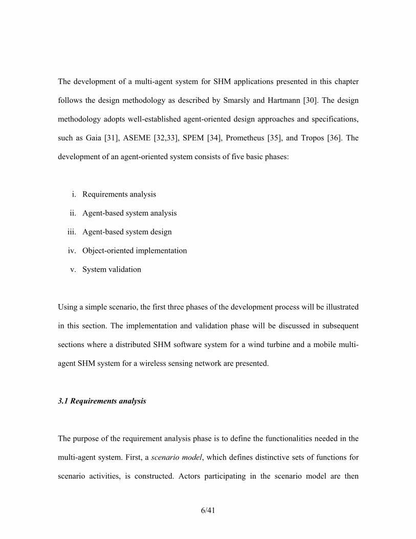
Fig. 1 shows an example of an actor diagram illustrating a scenario of a user’s request for
sensor measurement data. A (human) actor, labeled “user”, interested in analyzing the
condition of the observed structure requests measurement values from a database system.
Through the artificial (computational) actor “personal assistant”, the request is constructed
and forwarded to a “database wrapper” actor responsible for providing database access,
which handles the request and extracts the requested measurement data from the database
system.
Fig. 1. An actor diagram showing a scenario of a user’s request for measurement data.
3.2 Agent-based system analysis
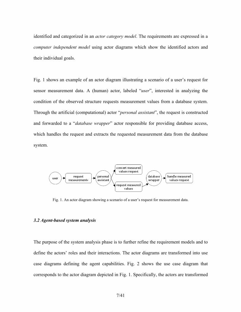
The purpose of the system analysis phase is to further refine the requirement models and to
define the actors’ roles and their interactions. The actor diagrams are transformed into use
case diagrams defining the agent capabilities. Fig. 2 shows the use case diagram that
corresponds to the actor diagram depicted in Fig. 1. Specifically, the actors are transformed
8/41
into roles, and the goals of the actors are transformed into use cases. Derived from the
“personal assistant” actor, a specific “technician assistant” role is identified and designed
to proactively support its counterpart (a human technician)—in this case requesting
measurement data. The use case diagram also shows the “technician” role derived from the
actor “user”, the “database wrapper” role, and the interdependencies between the roles
necessary to obtain the measurement data.
Fig. 2. Use case diagram for obtaining measurement data.
Following the Gaia methodology for agent-oriented analysis and design, a roles model and
an interaction model are generated [31]. Represented as roles schemata, the roles model
defines the functions to be carried out by a role. The interaction model, represented as a set
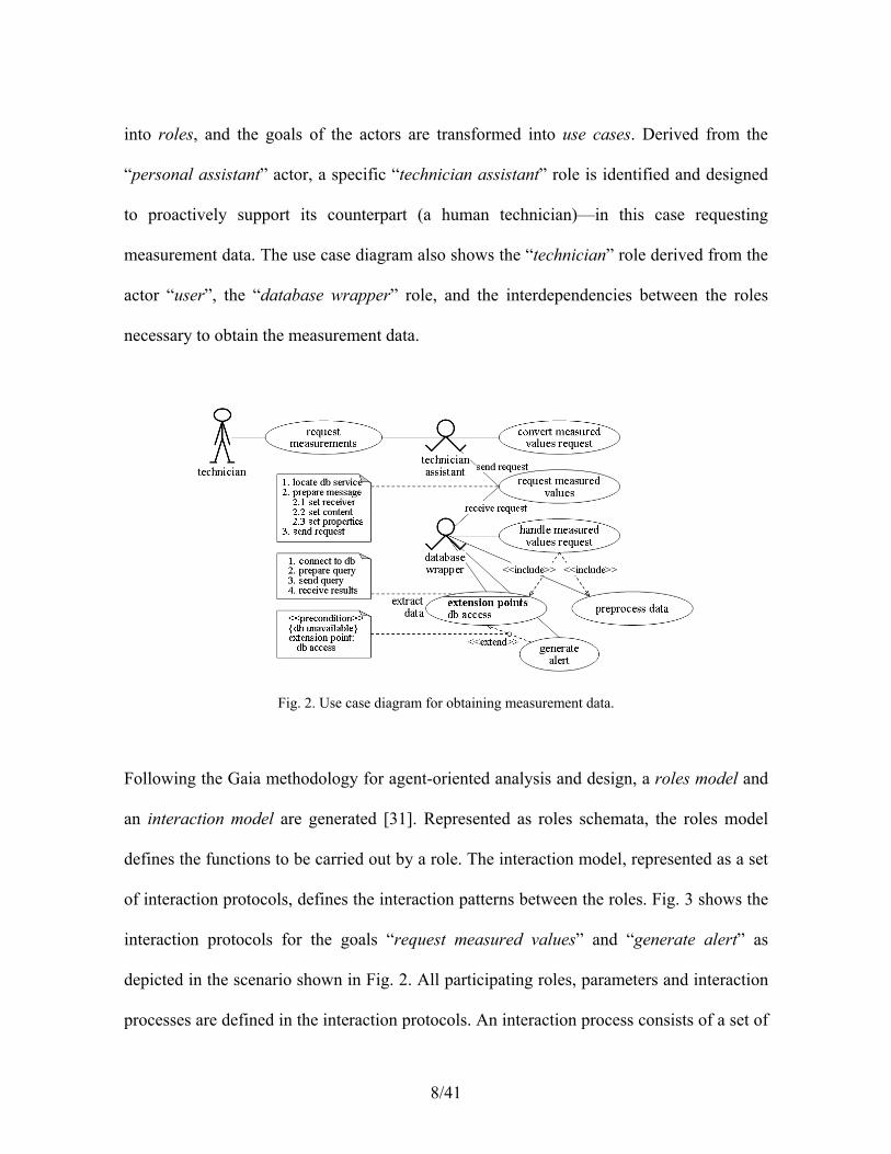
of interaction protocols, defines the interaction patterns between the roles. Fig. 3 shows the
interaction protocols for the goals “request measured values” and “generate alert” as
depicted in the scenario shown in Fig. 2. All participating roles, parameters and interaction
processes are defined in the interaction protocols. An interaction process consists of a set of
9/41
activities (shown underlined in Fig. 3), to be performed by an agent without involving
interactions with other agents, and protocols, which are activities that require interaction
between two or more agents.
Fig. 3. Interaction protocols associated with the “database wrapper” role.
Fig. 4 shows the roles schema of the “database wrapper” where the protocols and activities
that the role participates in are included. It should be pointed out that the roles model and
the interaction model, because of their strong interdependencies, are necessarily developed
together (and often iteratively) to ensure accuracy. Once all the roles and protocols are
developed, a functionality table is defined, which associates each activity of the roles
schemata with a technology or tool (e.g., a database or an engineering application) that is to
be employed to efficiently implement the roles.

10/41
Fig. 4. “Database wrapper” roles schema.
3.3 Agent-based system design
The design phase aims to develop low level details required to implement the multi-agent
systems using traditional object-oriented techniques. Inter-agent control and intra-agent
control are the main aspects to be considered in the design phase. The objective is to define
modular, reusable, and platform-independent models.
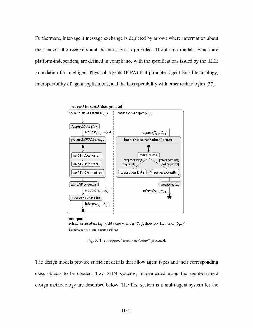
As an example, Fig. 5 shows a state diagram for the “requestMeasuredValues” protocol
depicted in Fig. 3. In the figure, activities are represented as monitoring states. The
activities that require agent interaction, such as “sendResults”, are shown in italics.
11/41
Furthermore, inter-agent message exchange is depicted by arrows where information about
the senders, the receivers and the messages is provided. The design models, which are
platform-independent, are defined in compliance with the specifications issued by the IEEE
Foundation for Intelligent Physical Agents (FIPA) that promotes agent-based technology,
interoperability of agent applications, and the interoperability with other technologies [37].
Fig. 5. The „requestMeasuredValues“ protocol.
The design models provide sufficient details that allow agent types and their corresponding
class objects to be created. Two SHM systems, implemented using the agent-oriented
design methodology are described below. The first system is a multi-agent system for the

12/41
monitoring of a wind turbine structure; the second system is a mobile multi-agent system
employed in a wireless sensor network. The implementation of specific agents in each
system will be described and their functions validated.
4 Agent-based structural health monitoring of a wind turbine
A structural health monitoring system has been implemented to monitor a 500 kW wind
turbine in Germany. The purpose of the SHM system is to systematically collect sensor
data for monitoring the structural condition of the wind turbine, to detect damages and
deteriorations, and to estimate its service lifespan. During the operation of the SHM system,
malfunctions of sensing units have been observed, interrupting the continuous data
acquisition and resulting in the loss of valuable sensor data. A multi-agent system is
designed and implemented to automatically detect system and component malfunctions and
to notify responsible human individuals in a timely manner. This section first provides an
overview of the SHM system installed on the wind turbine, and then presents the
implementation and validation of the multi-agent system for automated data monitoring and
malfunction detection.
4.1 Architecture of the SHM system
Fig. 6 shows the basic architecture of the SHM system which is composed of a sensor
network and a decentralized software system. Installed in the observed wind turbine, the
sensors are connected to data acquisition units controlled by an on-site local computer (on-

13/41
site server). Remotely connected to the sensor network, a decentralized software system
with software modules distributively residing on different computer systems is designed to
automatically execute crucial monitoring tasks, such as storing, converting, and analyzing
the collected data sets.
Fig. 6. Architecture of the SHM system.
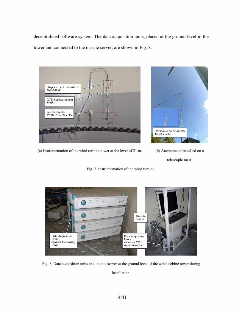
The wind turbine is instrumented with accelerometers, temperature sensors, and
displacement transducers to collect structural and environmental data necessary for
assessing the condition of the wind turbine. In addition, an ultrasonic anemometer is
mounted on a telescopic mast near the wind turbine for acquiring wind information. Fig. 7
depicts the sensor instrumentation in the interior of the wind turbine tower at the level of
about 21 m as well as the anemometer installed next to the wind turbine. The sampled and
digitized data sets are temporarily stored in the local computer and, using a permanently
installed digital subscriber line (DSL) connection, periodically forwarded to the
14/41
decentralized software system. The data acquisition units, placed at the ground level in the
tower and connected to the on-site server, are shown in Fig. 8.
(a) Instrumentation of the wind turbine tower at the level of 21 m.
(b) Anemometer installed on a
telescopic mast.
Fig. 7. Instrumentation of the wind turbine.
Fig. 8. Data acquisition units and on-site server at the ground level of the wind turbine tower during
installation.

15/41
The decentralized software system is designed to persistently store the data sets collected
by the sensor network; it also provides remote access to the SHM system for human users
as well as software programs. The software modules of the decentralized software system
are installed on different computers at the Institute for Computational Engineering (ICE) in
Bochum (Germany). They include (i) server systems for on-line data synchronization,
conversion, and transmission, (ii) a redundant array of independent disks (RAID) based
storage systems for periodic backups, (iii) a structured query language (MySQL) database
system for persistent data storage, and (iv) a web interface for remote access to the data.
Fig. 9a illustrates the web interface used to visualize the measurement data taken from the
wind turbine. Specifically, the figure shows the data recorded on April 24, 2011, including
wind speed as well as the radial and tangential horizontal accelerations of the tower at 63 m
height. Database connections are implemented utilizing Java Database Connectivity
(JDBC), an industry standard for database-independent connectivity between Java
applications and database systems. As shown in Fig. 9b, a direct database connection
allows authorized users to download the data from the database and supports remote access
to the data from external software programs, for example, to automatically execute damage
detection algorithms.

16/41
(a) Web interface connection. (b) Direct database connection.
Fig. 9. Acceleration and wind speed data measured on April 24, 2011 visualized through remote access.
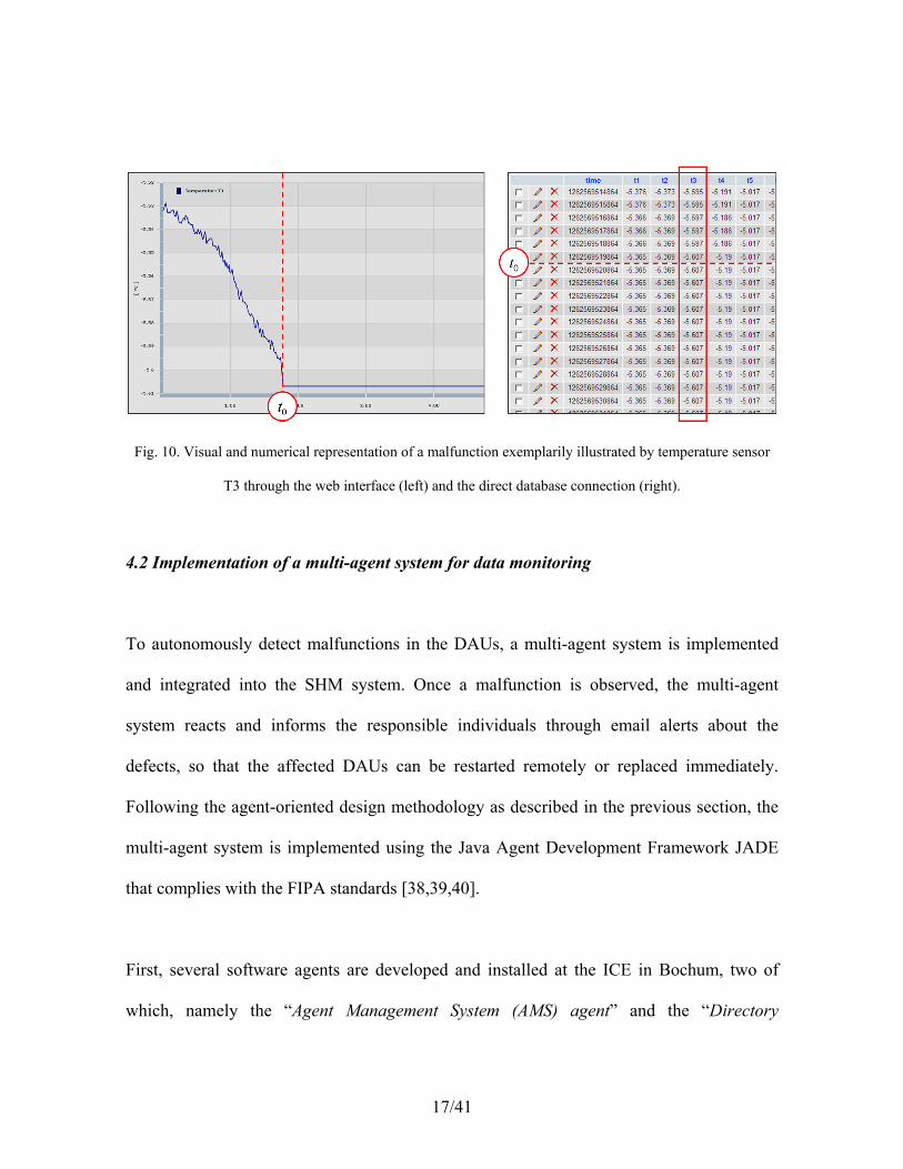
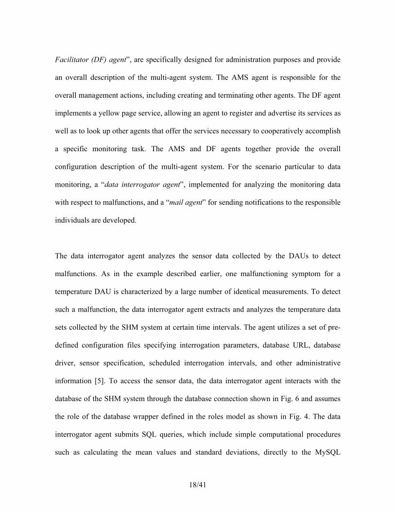
To illustrate a typical malfunction of a temperature data acquisition unit (DAU), Fig. 10
shows anomalies within the data sets collected by the DAUs. The malfunction is
characterized by a large number of identical measurements because of an internal system
problem in the DAU at time t0. The DAU, instead of recording and storing the actual
temperature measurements, repeatedly stores the last normal value (sensed right before the
occurrence of the malfunction).
17/41
Fig. 10. Visual and numerical representation of a malfunction exemplarily illustrated by temperature sensor
T3 through the web interface (left) and the direct database connection (right).
4.2 Implementation of a multi-agent system for data monitoring
To autonomously detect malfunctions in the DAUs, a multi-agent system is implemented
and integrated into the SHM system. Once a malfunction is observed, the multi-agent
system reacts and informs the responsible individuals through email alerts about the
defects, so that the affected DAUs can be restarted remotely or replaced immediately.
Following the agent-oriented design methodology as described in the previous section, the
multi-agent system is implemented using the Java Agent Development Framework JADE
that complies with the FIPA standards [38,39,40].
First, several software agents are developed and installed at the ICE in Bochum, two of
which, namely the “Agent Management System (AMS) agent” and the “Directory
18/41
Facilitator (DF) agent”, are specifically designed for administration purposes and provide
an overall description of the multi-agent system. The AMS agent is responsible for the
overall management actions, including creating and terminating other agents. The DF agent
implements a yellow page service, allowing an agent to register and advertise its services as
well as to look up other agents that offer the services necessary to cooperatively accomplish
a specific monitoring task. The AMS and DF agents together provide the overall
configuration description of the multi-agent system. For the scenario particular to data
monitoring, a “data interrogator agent”, implemented for analyzing the monitoring data
with respect to malfunctions, and a “mail agent” for sending notifications to the responsible
individuals are developed.
The data interrogator agent analyzes the sensor data collected by the DAUs to detect
malfunctions. As in the example described earlier, one malfunctioning symptom for a
temperature DAU is characterized by a large number of identical measurements. To detect
such a malfunction, the data interrogator agent extracts and analyzes the temperature data
sets collected by the SHM system at certain time intervals. The agent utilizes a set of pre-
defined configuration files specifying interrogation parameters, database URL, database
driver, sensor specification, scheduled interrogation intervals, and other administrative
information [5]. To access the sensor data, the data interrogator agent interacts with the
database of the SHM system through the database connection shown in Fig. 6 and assumes
the role of the database wrapper defined in the roles model as shown in Fig. 4. The data
interrogator agent submits SQL queries, which include simple computational procedures
such as calculating the mean values and standard deviations, directly to the MySQL

19/41
database, retrieves and analyzes the data. The security of database requests and data
transmissions is provided by the database system, which requires password and username
as well as secure drivers to be specified by an agent trying to access the database.
Upon detecting a malfunction, responsible individuals are immediately notified. On behalf
of the data interrogator agent, notifications are issued by the mail agent via an agent-based
email messaging service. First, the mail agent collects all relevant data necessary for
composing the emails. The email header is automatically created based on the metadata
obtained by the mail agent from the configuration files; the email content is created based
on the anomaly information received from the data interrogator agent. Once the emails are
composed, they are sent by the mail agent to the email clients (the individuals responsible
for the malfunctioning devices) using the Simple Mail Transfer Protocol (SMTP)—an
Internet standard for email transmission. Secure email messages are ensured by username-
and password-based authentications that the mail agent, similar to a human user, must
specify when trying to access the SMTP server.
The actions undertaken by an agent to fulfill a monitoring task require interactions with
other agents and the execution of local agent behaviors, which define how the agents
perceive, analyze and, in particular, react to various external events (e.g., sensor
malfunctions, detected anomalies or unavailable monitoring data). A local agent behavior
includes all relevant information about interaction protocols, communication details, and
specifications of languages required to carry out the agent’s design objectives. Agent
behaviors can be executed either sequentially or concurrently.

20/41
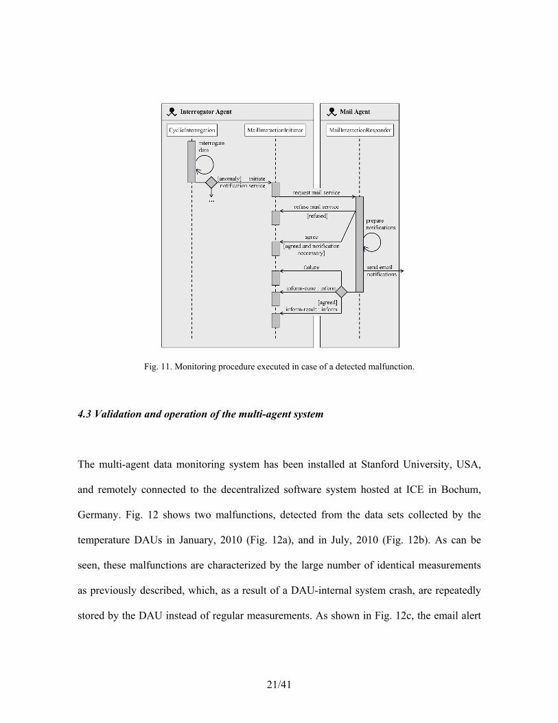
To illustrate the interactions between the agents for data monitoring, Fig. 11 shows three
agent behaviors, CyclicInterrogation, MailInteractionInitiator and
MailInteractionResponder, that are necessary to execute the “malfunction
detection” task. The behaviors CyclicInterrogation and MailInteraction-
Initiator belong to the data interrogator agent. The third agent behavior Mail-
InteractionResponder is an integral part of the mail agent. As shown in Fig. 11, the
malfunction detection executed by the data interrogator agent is initiated by its Cyclic-
Interrogation behavior, which periodically requests and analyzes the monitoring
data with respect to anomalies. Upon detecting an anomaly, that is, a possible malfunction,
the data interrogator agent requests the email notification service to notify the responsible
human individuals. To carry out the request, the data interrogator agent uses its Mail-
InteractionInitiator behavior for contacting the mail agent. The notification of
the human users through email is accomplished by the mail agent’s MailInteraction-
Responder behavior. As illustrated in Fig. 11, upon receiving and accepting a
notification request, the mail agent informs the data interrogator agent about its decision on
agreeing or refusing to handle the request. Once agreed, the mail agent processes the
request by preparing and sending the email notifications to the users responsible for
handling the detected anomaly. If the emails are sent successfully, the mail agent informs
the data interrogator agent, and the monitoring procedure is finalized. Otherwise, a failure
message is sent from the mail agent to the data interrogator agent, which may require
further action.
21/41
Fig. 11. Monitoring procedure executed in case of a detected malfunction.
4.3 Validation and operation of the multi-agent system
The multi-agent data monitoring system has been installed at Stanford University, USA,
and remotely connected to the decentralized software system hosted at ICE in Bochum,
Germany. Fig. 12 shows two malfunctions, detected from the data sets collected by the
temperature DAUs in January, 2010 (Fig. 12a), and in July, 2010 (Fig. 12b). As can be
seen, these malfunctions are characterized by the large number of identical measurements
as previously described, which, as a result of a DAU-internal system crash, are repeatedly
stored by the DAU instead of regular measurements. As shown in Fig. 12c, the email alert

22/41
sent in direct consequence of the malfunction includes detailed information on the detected
malfunction and is generated automatically by the mail agent using the analysis results
provided by the data interrogator agent.
(a) Malfunction occurred on January 3, 2010 (affected sensors: T1, …, T8).
(b) Malfunction occurred on July 19, 2010 (affected sensors: T5, T6, T7, T8).
(c) Extract of the email notification generated and sent in consequence of malfunction (b).
Fig. 12. Visual representation of two detected malfunctions and email notification generated and sent by the
software agents.
In this application example, a multi-agent system has been presented for the autonomous
detection of system malfunctions within an existing wind turbine SHM system. Since its

23/41
initial deployment various anomalies in the collected data have been automatically
detected. The affected data acquisition units have been remotely restarted by the
technicians in a timely fashion. Consequently, considerable amounts of valuable sensor
data were saved and are available for assessing the structural condition of the wind turbine.
The long-term deployment of the multi-agent system has demonstrated the performance,
the reliability and the robustness of the multi-agent approach for autonomous structural
health monitoring.
5 An agent-based wireless sensor network for structural health monitoring
Eliminating the need for installing communication cables, wireless sensor networks have
been proposed as a viable alternative for structural health monitoring systems; they reduce
material as well as labor costs and allow flexible network configurations. However, because
of the limited internal resources of wireless sensor nodes, new and innovative concepts are
necessary to implement resource-efficient operation for reliable monitoring. Multi-agent
technology, supporting dynamic code migration and automated, cooperative information
processing, is explored as a means to achieve resource efficiency and system reliability.
Code migration—agents physically migrating from one wireless sensor node to another—
enables a SHM system to dynamically adapt to changes and to altered conditions of its
environment, and to reduce network load and latency. Software agents are installed on the
wireless sensor nodes continuously executing simple resource-efficient routines to locally
process the measurement data. When a sensor or the sensor network detects potential
structural anomalies, specialized agents are physically migrating to the relevant sensor

24/41
nodes; the migrating agents perform more complex—and resource-consuming—algorithms
to further analyze the sensor data locally within the sensor nodes. In essence, multi-agent
technology is incorporated into a wireless sensor network
1. to allow the sensor nodes to collaboratively self-assess the condition of the observed
structure and
2. to enhance the resource efficiency of the sensor nodes with respect to data
communication and on-board memory usage.
5.1 Implementation of an agent-based wireless sensor network
As depicted in Fig. 13, the wireless sensor network consists of a base node and clusters of
sensor network systems. Each cluster is composed of a head node, that manages the cluster,
and a number of sensor nodes that collect and locally analyze the data. The base node is
connected to a local computer that, in the prototype implementation presented herein,
includes a MySQL database system for persistent storage of selective sensor data and an
information pool that stores properties of the observed structure (such as modal properties),
sensor information, and a catalog of available data analysis algorithms.
25/41
Fig. 13. Hierarchical architecture of the wireless sensor network.
For rapid prototype purposes, Oracle SunSPOT devices are deployed for the wireless
sensor network. The sensor nodes, built upon the IEEE 802.15.4 standard for wireless
networks, comprise a fully capable, CLDC 1.1-compatible Java Platform, Micro Edition
(Java ME). The computational core is a 32-bit Atmel AT91RM9200 executing at 180 MHz
maximum internal clock speed. Each wireless sensor node includes a 3-axis linear
accelerometer that measures a bandwidth of 4.0 kHz over a scale of ± 6 g as well as an
integrated temperature sensor, a number of analog inputs, momentary switches, general
purpose I/O pins and high current output pins [41,42]. For the software implementation, a
Squawk Java virtual machine, running without an underlying operating system, ensures a
light-weight execution of multiple embedded applications on the sensor nodes [43,44].
Two basic types of software agents are implemented, namely the “on-board agents”
permanently residing at the head and sensor nodes, and the “migrating agents” located at
the head nodes to be sent to the sensor nodes upon request. The on-board agents installed
on the sensor nodes are capable of making their own decisions and acting in the wireless
sensor network with a high degree of autonomy. They continuously take measurements
from the observed structure, perform simple routines for detecting suspected abnormalities
and aggregate the measurement data (e.g., to extract representative features and values from
the collected data sets). The aggregated data is then transmitted to the database system
installed on the local computer for persistent storage.

26/41
As opposed to on-board agents that are permanently residing at the nodes, migrating agents
are capable of physically migrating from one node to another in real-time. While the on-
board agents at the sensor nodes are continuously executing relatively simple yet resource-
efficient routines, the migrating agents are designed to carry out more comprehensive data
analysis algorithms directly on a sensor node. Acting upon a request by an on-board agent
in case of detected or suspected abnormal changes of the monitored structure, a migrating
agent is dynamically composed with the most appropriate diagnostic algorithm selected
from the information pool for analyzing the detected anomaly. Fig. 14 shows an abridged
UML class diagram illustrating the main classes of the mobile multi-agent system. The
discussion below focuses on the design and implementation of the on-board and migrating
agents.
Fig. 14. Abridged UML class diagram of the mobile multi-agent system.

27/41
On the sensor nodes, two categories of on-board agents, “administrator agents” and
“temperature analysis agents”, are prototypically implemented. An administrator agent is
designed to manage the local resources of a sensor node. For example, an administrator
agent is responsible for battery level monitoring and for memory management of the sensor
node. The temperature analysis agent continuously collects and aggregates the temperature
data, and detects significant temperature changes in the structure that may signify
abnormality. The agent then communicates the aggregated data and the analysis results
periodically to the head node, which in turn forwards the data through the base node to the
local computer for persistent storage and further processing.
On-board agents are also installed on the head nodes although they play a very different
role than those at the sensor nodes. Unlike on-board agents situated on the sensor nodes, the
on-board agents operating on head nodes are primarily administrative agents, which serve
as local coordinators for their cluster without being responsible for sensing or analyzing the
measurement data. Furthermore, the on-board agents on the head nodes are responsible for
performing cluster-internal management and administration tasks, including
communication with other clusters and the base node.
Migrating agents implement the different analysis algorithms to be utilized for diagnostic
purposes. Technically, the bytecodes of the migrating agents and algorithms are stored on
the head nodes. Depending on the symptoms received from the sensor nodes, different
types of migrating agents, comprising different analysis algorithms, are assembled during

28/41
runtime. The corresponding agent objects, together with all relevant agent capabilities and
algorithms, are composed on the head node, and transmitted to the sensor nodes to carry out
the diagnostic functions.
For implementing the wireless agent migration, the characteristics of the Squawk Java
virtual machine, as described earlier, are advantageously utilized. Squawk employs an
application isolation mechanism that represents each application as an object. Being
completely isolated from other objects, objects running on a node, such as migrating agents,
can be paused, serialized, and physically transferred (together with agent behaviors, agent
states, and required algorithms), all while Squawk instances are running on other nodes.
The mobile multi-agent system is implemented based on the “MAPS” agent architecture as
proposed by Aiello et al. [45].
5.2 Validation of the agent-based wireless sensor network
For the proof of concept using multi-agent technology for wireless structural health
monitoring, validation tests are conducted in the laboratory. As shown in Fig. 15 and Fig.
16, the wireless sensor nodes are mounted on an aluminum plate that serves as a test
structure. Heat is introduced to the test structure simulating an anomaly to be detected and
handled by the wireless SHM system. The test structure, a 900 mm × 540 mm aluminum
plate (t = 0.635 mm) with one edge being clamped, is instrumented with an array of 9
precision temperature sensors, type LM335A manufactured by National Semiconductor.
For this experimental test, the wireless monitoring system installed is composed of one

29/41
cluster – comprising one head node and three sensor nodes—as well as one base node that
connects the wireless monitoring system to the local computer. As shown in Fig. 15, the
test structure is divided into three monitoring sections A, B, and C. Each of the three sensor
nodes (SA, SB, and SC) is responsible for monitoring one section and is connected to three
temperature sensors that are located within its monitoring section. In addition, each sensor
node includes an integrated STMicroelectronics LIS3L02AQ accelerometer. Fig. 16 shows
the fully instrumented test structure. The main objectives of the validation tests are (i) to
verify the condition monitoring capabilities of the wireless monitoring system and (ii) to
obtain system performance data for evaluating the resource efficiency achieved by the
newly proposed concepts.
Fig. 15. Overview of the prototype wireless sensor network.

30/41
Fig. 16. Laboratory setup: wireless sensor network installed on an aluminum test structure.
In the laboratory tests, the on-board agents operating on the sensor nodes are continuously
sensing temperature measurements using the temperature sensors attached. The collected
temperature measurements are locally checked with a very simple and resource-efficient
procedure whether they exceed a certain threshold, then forwarded to the local computer
and stored in the database. To simulate structural changes in the test structure, heat is
introduced underneath the aluminum plate near monitoring section B. A critical plate
temperature Tcrit = 60 °C is pre-defined as a threshold value indicating that a potential
anomaly of the structure may occur and attention by the monitoring system may be
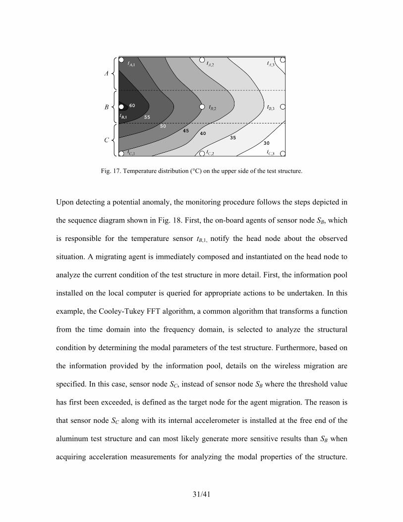
required. Fig. 17 illustrates the temperature distribution calculated from the temperature
measurements collected by the on-board agents when Tcrit is reached at the temperature
sensor tB,1.
31/41
Fig. 17. Temperature distribution (°C) on the upper side of the test structure.
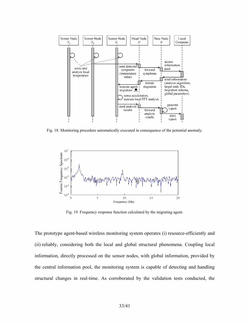
Upon detecting a potential anomaly, the monitoring procedure follows the steps depicted in
the sequence diagram shown in Fig. 18. First, the on-board agents of sensor node SB, which
is responsible for the temperature sensor tB,1, notify the head node about the observed
situation. A migrating agent is immediately composed and instantiated on the head node to
analyze the current condition of the test structure in more detail. First, the information pool
installed on the local computer is queried for appropriate actions to be undertaken. In this
example, the Cooley-Tukey FFT algorithm, a common algorithm that transforms a function
from the time domain into the frequency domain, is selected to analyze the structural
condition by determining the modal parameters of the test structure. Furthermore, based on
the information provided by the information pool, details on the wireless migration are
specified. In this case, sensor node SC, instead of sensor node SB where the threshold value
has first been exceeded, is defined as the target node for the agent migration. The reason is
that sensor node SC along with its internal accelerometer is installed at the free end of the
aluminum test structure and can most likely generate more sensitive results than SB when
acquiring acceleration measurements for analyzing the modal properties of the structure.

32/41
Together with the selected algorithm and migration path, modal parameters for the original
state of the test structure are also passed onto the head node for composing the migrating
agent.
Subsequently, the migrating agent composed and initialized on the head node is equipped
with a Cooley-Tukey FFT algorithm and global system information, such as first modal
frequency of the test structure in its original state. Once migrated to sensor node SC, the
migrating agent accesses the sensor node’s internal accelerometer, collects the acceleration
measurements, and calculates the current first modal frequency of the test structure. Fig. 19
shows the frequency response function computed by the migrating agent based on the
vertical accelerations at SC. The current first modal frequency is calculated to be 1.6 Hz
(which is not much different from the first modal frequency of the structure in its original
state). The results are sent by the migrated agent to the local computer, where they are
stored in the form of a safety report accessible by any responsible individuals.
33/41
Fig. 18. Monitoring procedure automatically executed in consequence of the potential anomaly.
Fig. 19. Frequency response function calculated by the migrating agent.
The prototype agent-based wireless monitoring system operates (i) resource-efficiently and
(ii) reliably, considering both the local and global structural phenomena. Coupling local
information, directly processed on the sensor nodes, with global information, provided by
the central information pool, the monitoring system is capable of detecting and handling
structural changes in real-time. As corroborated by the validation tests conducted, the

34/41
resource consumption of the prototype system, compared to conventional systems, could
significantly be reduced. Owing to the migration-based approach, a reduction of more than
90% of wirelessly communicated data could be achieved as compared with traditional
approaches that communicate all collected raw sensor data to a central server. In addition,
the memory consumption, as measured in the laboratory experiments, has been reduced by
approximately 70 kB per sensor node in comparison with those conventional approaches
that perform embedded analyses directly on the sensor nodes without applying dynamic
code migration.
6 Summary
This chapter describes the deployment of multi-agent techniques in the development of
structural health monitoring systems. A methodology, from requirements analysis to system
design, for developing agent-based monitoring systems has been presented, followed by
two application examples elucidating the implementation and validation of the agent-based
approach. In the first example, an agent-based decentralized software system for the
autonomous detection of SHM system malfunctions has been presented. The agent-based
software system has been integrated into an existing decentralized SHM system for real-
time monitoring of a wind turbine to detect system and component malfunctions. In the
second example, multi-agent technology has been deployed in a wireless sensor network
for accurate monitoring and a reliable, timely detection of changes in the structural
conditions based on mobile code migration. Specifically, the design, the implementation,
and the validation of an agent-based wireless monitoring system, able to autonomously

35/41
detect structural changes, has been demonstrated. Because of its modularity and
extendibility, multi-agent technology is a promising paradigm for the implementation of
robust and accurate SHM systems, allowing continuing upgrades and new advancements to
be incorporated in an autonomous and distributed manner.
7 Acknowledgments
This research is partially funded by the German Research Foundation (DFG) under grant
SM 281/1-1, awarded to Dr. Kay Smarsly, and by the U.S. National Science Foundation
(NSF) under grant CMMI-0824977, awarded to Professor Kincho H. Law. The authors
would like to express their gratitude to Professor Dietrich Hartmann of the Ruhr University
Bochum, Germany, for his generous support and for his leadership in the development of
the SHM system for the wind turbine, which has been instrumented within the DFG-funded
research project HA 1463/20-1.
References
1. HSNW, 150,000 U.S. bridges are rated 'deficient', Homeland Security News Wire,
Locust Valley, NY, USA, 2010.
2. Smarsly, K., Law, K.H. and König, M., Resource-efficient wireless monitoring
based on mobile agent migration, in Proc. SPIE (Vol. 7984): Health Monitoring
of Structural and Biological Systems 2011, Kundu, T., Ed., 2011, digital library.

36/41
3. Moore, M. et al., Reliability of visual inspection for highway bridges, volume I:
Final report, FHWA-RD-01-020, U.S. Federal Highway Administration,
McLean, VA, USA, 2001.
4. Wang, Y., Wireless sensing and decentralized control for civil structures: Theory
and implementation, Doctoral Thesis, Stanford University, Stanford, CA, USA,
2007.
5. Smarsly, K., Law, K.H. and Hartmann, D., A multiagent-based collaborative
framework for a self-managing structural health monitoring System, ASCE
Journal of Computing in Civil Engineering, 26, 76, 2012.
6. Lynch, J.P., Overview of wireless sensors for real-time health monitoring of civil
structures, in Proc. 4th International Workshop on Structural Control and
Monitoring, New York City, NY, USA, June 10-11, 2004.
7. Smarsly, K., Law, K.H. and König, M., Autonomous structural condition
monitoring based on dynamic code migration and cooperative information
processing in wireless sensor networks, in Proc. of the 8th International
Workshop on Structural Health Monitoring 2011, Chang, F.-K., Ed., DEStech
Publications, Inc., Lancaster, PA, USA, 2011, 1996.
8. Perugini, D., et al., Agents in logistics planning – Experiences with the coalition
agents experiment project, in Proc. Second International Joint Conference on
Autonomous Agents and Multiagent Systems (AAMAS 2003), Melbourne,
Australia, July 14-18, 2003.
9. Graudina, V. and Grundspenkis, J., Technologies and multi-agent system
architectures for transportation and logistics support: An overview, in Proc.

37/41
International Conference on Computer Systems and Technologies –
CompSysTech’ 2005, Varna, Bulgaria, June 16-17, 2005.
10. Burmeister, B., Haddadi, A. and Matylis, G., Application of multi-agent systems
in traffic and transportation, IEE Proceedings Software Engineering, 144, 51,
1997.
11. Bazzan, A.L.C. and Klügl, F., Multi-Agent Systems For Traffic And
Transportation Engineering, 1st ed., Information Science Reference, Hershey,
PA, USA, 2009.
12. Don Perugini, et al., Agents for military logistic planning, in Proc. of the 15th
European Conference on Artificial Intelligence (ECAI-2002), Lyon, France, July
21-26, 2002.
13. McArthur, S.D.J. et al., Multi-agent systems for power engineering applications –
part I: concepts, approaches and technical challenges, IEEE Transactions on
Power Systems, 22, 1743, 2007.
14. McArthur, S.D.J. et al., Multi-agent systems for power engineering applications –
part II: concepts, approaches and technical challenges, IEEE Transactions on
Power Systems, 22, 1753, 2007.
15. Gunkel, A., The application of multi-agent systems for water resources research –
Possibilities and limits, Diploma Thesis, Institut für Hydrologie der Albert-
Ludwigs-Universität Freiburg i.Br., Freiburg, Germany, November 2005
16. Shen, W. et al., Applications of agent-based systems in intelligent manufacturing:
An updated review, Advanced Engineering Informatics, 20, 415, 2006.

38/41
17. Maturana, F. et al., MetaMorph: An adaptive agent-based architecture for
intelligent manufacturing, International Journal of Production Research, 37,
2159, 1999.
18. Fuhrmann, T. and Neuhofer, B., Multi-agent systems for environmental control
and intelligent buildings, Report, Department of Computer Science, University of
Salzburg, Austria, 2006.
19. Qiao, B., Liu, K. and Guy, C., A multi-agent system for building control, in Proc.
IEEE/WIC/ACM International Conference on Intelligent Agent Technology
(IAT'06), Hong Kong, China, December 18-22, 2006.
20. Jennings, N.R. and Wooldridge, M.J., Applications of Intelligent Agents, in Agent
Technology: Foundations, Applications and Markets, Jennings, N.R. and
Wooldridge, M.J., Eds., Springer, Berlin, Germany, 1998, 3.
21. Uhrmacher, A.M., Weyns, D. and Mosterman, P.J. (eds.), Multi-Agent Systems.
Simulation and Applications (Computational Analysis, Synthesis, and Design of
Dynamic Models Series), CRC Press Inc, Taylor & Francis Group: Boca Raton
London, UK, 2009.
22. Nwana, H.S. and Ndumu, D.T., An introduction to agent technology, in Proc.
Software Agents and Soft Computing: Towards Enhancing Machine Intelligence,
Concepts and Applications, Nwana, H.S. and Azarmi, N., Eds., Springer, London,
UK, 1997, 3.
23. Wooldridge, M.J. and Jennings, N.R., Intelligent agents: Theory and practice, The
Knowledge Engineering Review, 10, 115, 1995.

39/41
24. Nwana, H.S., Software agents: an overview, The Knowledge Engineering Review,
11, 205, 1996.
25. Moraitakis, N., Intelligent software agents application and classification, in
Surveys and Presentations in Information Systems Engineering, Imperial College
London, UK, 1997.
26. Maes, P., Artificial life meets entertainment: life-like autonomous agents,
Communications of the ACM, 38, 108, 1995.
27. Russell, S. and Norvig, P., Artificial Intelligence: A Modern Approach, 1st ed.,
Prentice-Hall Inc., Upper Saddle River, NJ, USA, 1995.
28. Wooldridge, M.J., An Introduction To MultiAgent Systems, John Wiley & Sons,
Ltd., West Sussex, UK, 2002.
29. Wooldridge, M.J., Lomuscio, A. (2000). Multi-Agent VSK Logic. Proceedings of
the Seventh European Workshop on Logics in Artificial Intelligence (JELIAI-
2000), Springer.
30. Smarsly, K. and Hartmann, D., Agent-oriented development of hybrid wind
turbine monitoring systems, in Proc. International Conference on Computing in
Civil and Building Engineering, Tizani, W., Ed., Nottingham University Press,
Nottingham, UK, 2010, 427.
31. Wooldridge, M.J., Jennings, N.R. and Kinny, D., The Gaia methodology for
agent-oriented analysis and design, Journal of Autonomous Agents and Multi-
Agent Systems, 3, 285, 2000.

40/41
32. Moraitis, P. and Spanoudakis, N.I., The Agent Systems Methodology (ASEME):
A preliminary report, in Proc. 5th European Workshop on Multi-Agent Systems
EUMAS 07, Hammamet, Tunisia, December 13-14, 2007.
33. Moraitis, P. and Spanoudakis, N.I., The Gaia2Jade process for MAS development,
Applied AI, 20, 251, 2006.
34. Object Management Group (OMG), Software and systems process engineering
meta-model specification, Version 2, OMG document number: formal/2008-04-
01, online: http://www.omg.org/spec/SPEM/2.0/PDF (accessed January 17, 2012),
Object Management Group, 2008.
35. Padgham, L. and Winikoff, M., Prometheus: A methodology for developing
intelligent agents, in Proc. 17th Conf. on Object-Oriented Progr., Systems,
Languages, and Appl., Seattle, WA, USA, November 4-8, 2002.
36. Susi, A. et al., The Tropos metamodel and its use, Informatica, 29, 401, 2005.
37. FIPA – Foundation for Intelligent Physical Agents, http://www.fipa.org.
38. Bellifemine, F., et al., JADE – A White Paper, EXP in search of innovation, 3, 6,
2003.
39. Bellifemine, F., Caire, G. and Greenwood, D., Developing Multi-Agent Systems
with JADE, 1st ed., John Wiley & Sons, Ltd., West Sussex, UK, 2007
40. Bellifemine, F., et al., Jade Programmer's Guide, online:
http://jade.tilab.com/doc/programmersguide.pdf (accessed January 17, 2012)
Telecom Italia S.p.A., Milan, Italy, 2010.
41. Oracle Corporation, SunSPOT Programmer's Manual – Release v6.0, Oracle
Corporation, Redwood Shores, CA, USA, 2010.

41/41
42. Oracle Corporation, Main Board Technical Datasheet Rev 8.0, Oracle
Corporation, Redwood Shores, CA, USA, 2010.
43. Smith, R.B., Cifuentes, C. and Simon, D., Enabling Java TM for small wireless
devices with Squawk and SpotWorld, in Proc. Second Workshop on Building
Software for Pervasive Computing, San Diego, CA, USA, 16 October, 2005.
44. Simon, D. et al., Java on the bare metal of wireless sensor devices: the squawk
Java Virtual Machine, in Proc. Second International Conference on Virtual
Execution Environments, Ottawa, Canada, June 14-16, 2006.
45. Aiello, F. et al., A Java-based agent platform for programming wireless sensor
networks, The Computer Journal, 54, 439, 2011.