ADVANCED SPACE MECHANISMS DESIGN USING ADDITIVE …
7
ADVANCED SPACE MECHANISMS DESIGN USING ADDITIVE LAYER MANUFACTURING Antje Deckert (1) , Jörg Eckler (1) , Heiko Jahn (1) , Sebastian Scheiding (1) (1) Astro- und Feinwerktechnik Adlershof GmbH, Albert-Einstein-Str. 12 12489 Berlin (Germany), Email: [email protected] ABSTRACT Astro- und Feinwerktechnik Adlershof GmbH (Astrofein) together with its partner Robo-Technology GmbH is currently developing a Flexible Orbital Manipulator (FOM) for various On-Orbit Servicing (OOS) tasks feasible for small satellite platforms. Within the development, Astrofein is responsible for the electromechanical manipulator arm design. One of the major design challenges was to find a lightweight arm design feasible for small satellites by providing enough stiffness for bearing the launch loads and ensuring good dynamical behaviour during operation. This could only be achieved by optimised structural design of the link and joint structures using Additive Layer Manufacturing (ALM). The paper provides an overview on the system design approach that has been chosen to meet the requirements for a lightweight manipulator arm. The major achievements when using ALM technology for the structural elements are presented. Breadboard test results are discussed for different design aspects incl. lessons- learnt and critical design aspects. SPACE MANIPULATORS FOR ON-ORBIT SERVICING When reviewing literature on space manipulators, it turns out that most of the flown manipulators have been or are used on ISS/Space Shuttle missions, e.g. (SS)RMS ((Space Shuttle) Remote Manipulator System, also known as CANADARM 1 and 2) and JEMRMS (Japanese Experiment Module Robotics Systems), refer to [1]. Some missions using manipulators for satellite servicing have already been completed successfully, e.g. ETS-VII and Orbital Express, refer to [2] and [3]. Currently, DARPA (Defense Advanced Research Projects Agency) is preparing an OOS mission called “Robotic Servicing of Geosynchronous Satellites (RSGS)” using the “Front-End Robotics Enabling Near- Term Demonstration (FREND)” robotic arm [4]. Figure 1. FREND arm [5] With increasing number of launched satellites, also the demand for OOS and active space debris removal missions increases. Therefore, using technologies and designs that allow for scalability and design flexibility in terms of mission tasks has been found to be best suited for the variety of systems to be serviced. Combining this design approach with the advantages of small satellite platforms, such as increased number of launch opportunities, shorter lead times and use of automotive/industrial standards, a sustainable solution for future space flight challenges is provided by FOM. Figure 2.Artit’s impression of FOM in space MANIPULATOR ARM DESIGN AND DRIVING REQUIREMENTS FOM is designed to fulfil one (or more) of the following tasks: - Monitoring and diagnostics as a basic functionality, - Grappling of small client spacecraft, - Replacing ORU’s (Orbital Replaceable Units) or other prepared components, - Deployment and assembly assistance for small/ medium structures. Since the required servicing platform has been defined to be at the range of a small satellite, i.e. below 300 kg, resources were a main driver for the robotic arm design. The main parameters of the designed manipulator arm are provided in Tab. 1. Table 1.FOM main parameters Parameter Value Degrees of Freedom (DoF) Arm: 6 Tool: 2* Max. workspace radius 1,500 mm Min. workspace radius 450 mm Mass (excl. margin) 37 kg (Arm incl. tool: 22.7 kg) Load capacity Grappling: 4 N / 3 Nm Handling: 8 N / 8 Nm Connector
Transcript of ADVANCED SPACE MECHANISMS DESIGN USING ADDITIVE …
ADVANCED SPACE MECHANISMS DESIGN USING ADDITIVE LAYER
MANUFACTURING
Antje Deckert (1), Jörg Eckler (1), Heiko Jahn (1), Sebastian Scheiding (1)
(1) Astro- und Feinwerktechnik Adlershof GmbH, Albert-Einstein-Str. 12 12489 Berlin (Germany),
Email: [email protected]
ABSTRACT
Astro- und Feinwerktechnik Adlershof GmbH
(Astrofein) together with its partner Robo-Technology
GmbH is currently developing a Flexible Orbital
Manipulator (FOM) for various On-Orbit Servicing
(OOS) tasks feasible for small satellite platforms. Within
the development, Astrofein is responsible for the
electromechanical manipulator arm design.
One of the major design challenges was to find a
lightweight arm design feasible for small satellites by
providing enough stiffness for bearing the launch loads
and ensuring good dynamical behaviour during
operation. This could only be achieved by optimised
structural design of the link and joint structures using
Additive Layer Manufacturing (ALM).
The paper provides an overview on the system design
approach that has been chosen to meet the requirements
for a lightweight manipulator arm. The major
achievements when using ALM technology for the
structural elements are presented. Breadboard test results
are discussed for different design aspects incl. lessons-
learnt and critical design aspects.
SPACE MANIPULATORS FOR ON-ORBIT
SERVICING
When reviewing literature on space manipulators, it turns
out that most of the flown manipulators have been or are
used on ISS/Space Shuttle missions, e.g. (SS)RMS
((Space Shuttle) Remote Manipulator System, also
known as CANADARM 1 and 2) and JEMRMS
(Japanese Experiment Module Robotics Systems), refer
to [1]. Some missions using manipulators for satellite
servicing have already been completed successfully, e.g.
ETS-VII and Orbital Express, refer to [2] and [3].
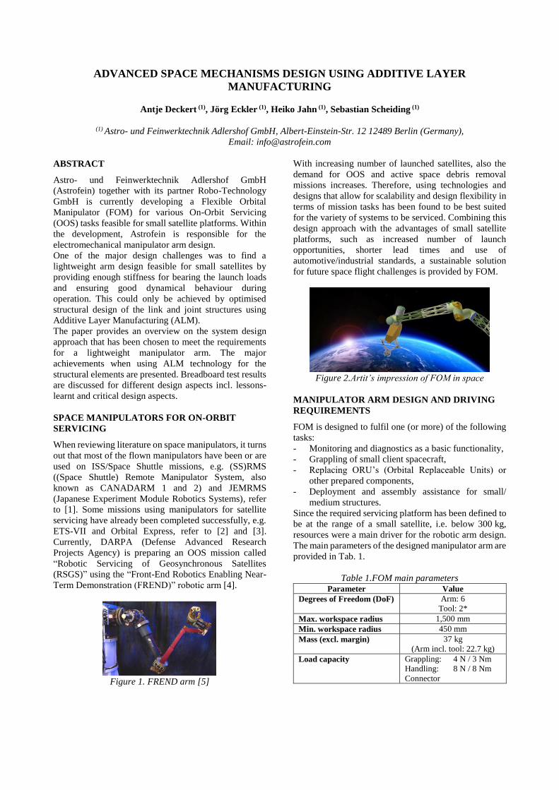
Currently, DARPA (Defense Advanced Research
Projects Agency) is preparing an OOS mission called
“Robotic Servicing of Geosynchronous Satellites
(RSGS)” using the “Front-End Robotics Enabling Near-
Term Demonstration (FREND)” robotic arm [4].
Figure 1. FREND arm [5]
With increasing number of launched satellites, also the
demand for OOS and active space debris removal
missions increases. Therefore, using technologies and
designs that allow for scalability and design flexibility in
terms of mission tasks has been found to be best suited
for the variety of systems to be serviced. Combining this
design approach with the advantages of small satellite
platforms, such as increased number of launch
opportunities, shorter lead times and use of
automotive/industrial standards, a sustainable solution
for future space flight challenges is provided by FOM.
Figure 2.Artit’s impression of FOM in space
MANIPULATOR ARM DESIGN AND DRIVING
REQUIREMENTS
FOM is designed to fulfil one (or more) of the following
tasks:
- Monitoring and diagnostics as a basic functionality,
- Grappling of small client spacecraft,
- Replacing ORU’s (Orbital Replaceable Units) or
other prepared components,
- Deployment and assembly assistance for small/
medium structures.
Since the required servicing platform has been defined to
be at the range of a small satellite, i.e. below 300 kg,
resources were a main driver for the robotic arm design.
The main parameters of the designed manipulator arm are
provided in Tab. 1.
Table 1.FOM main parameters Parameter Value
Degrees of Freedom (DoF) Arm: 6
Tool: 2*
Max. workspace radius 1,500 mm
Min. workspace radius 450 mm
Mass (excl. margin) 37 kg
(Arm incl. tool: 22.7 kg)
Load capacity Grappling: 4 N / 3 Nm
Handling: 8 N / 8 Nm
Connector
Parameter Value
plugging: 90 N / 2 Nm
Max. end effector speed 50 mm/s
Max. power consumption 300 W
* Task/mission specific.
When compared to similar systems, e.g. the ETS-VII arm
with six DoF, a reach of 2 m and a weight of 150 kg, the
required lightweight design becomes even more visible.
The FOM manipulator arm is depicted in Fig. 3. The
complete structural design is mainly driven by the free-
shaping opportunities of Additive Layer Manufacturing.
Its elements are described more detailed in the following
section.
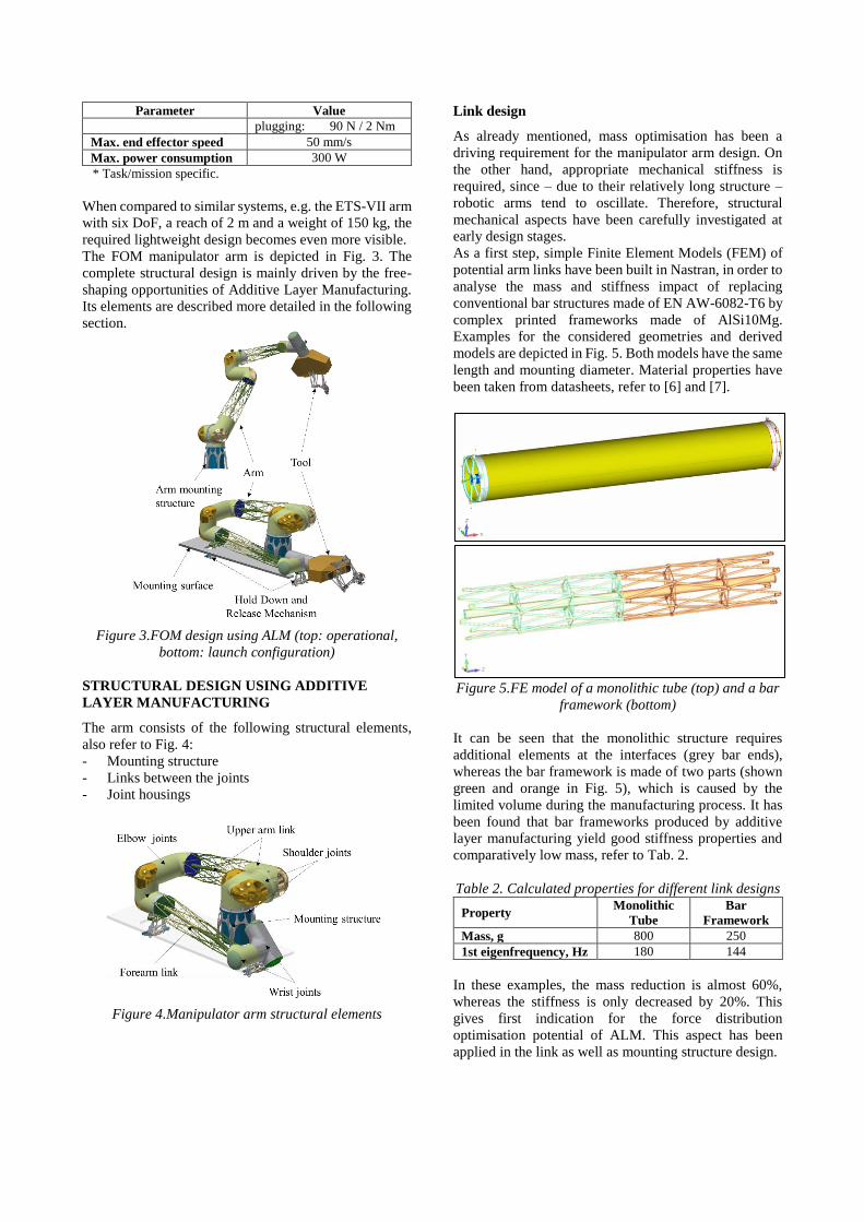
Figure 3.FOM design using ALM (top: operational,
bottom: launch configuration)
STRUCTURAL DESIGN USING ADDITIVE
LAYER MANUFACTURING
The arm consists of the following structural elements,
also refer to Fig. 4:
- Mounting structure
- Links between the joints
- Joint housings
Figure 4.Manipulator arm structural elements
Link design
As already mentioned, mass optimisation has been a
driving requirement for the manipulator arm design. On
the other hand, appropriate mechanical stiffness is
required, since – due to their relatively long structure –
robotic arms tend to oscillate. Therefore, structural
mechanical aspects have been carefully investigated at
early design stages.
As a first step, simple Finite Element Models (FEM) of
potential arm links have been built in Nastran, in order to
analyse the mass and stiffness impact of replacing
conventional bar structures made of EN AW-6082-T6 by
complex printed frameworks made of AlSi10Mg.
Examples for the considered geometries and derived
models are depicted in Fig. 5. Both models have the same
length and mounting diameter. Material properties have
been taken from datasheets, refer to [6] and [7].
Figure 5.FE model of a monolithic tube (top) and a bar
framework (bottom)
It can be seen that the monolithic structure requires
additional elements at the interfaces (grey bar ends),
whereas the bar framework is made of two parts (shown
green and orange in Fig. 5), which is caused by the
limited volume during the manufacturing process. It has
been found that bar frameworks produced by additive
layer manufacturing yield good stiffness properties and
comparatively low mass, refer to Tab. 2.
Table 2. Calculated properties for different link designs
Property Monolithic
Tube
Bar
Framework
Mass, g 800 250
1st eigenfrequency, Hz 180 144
In these examples, the mass reduction is almost 60%,
whereas the stiffness is only decreased by 20%. This
gives first indication for the force distribution
optimisation potential of ALM. This aspect has been
applied in the link as well as mounting structure design.

In addition to the structural mechanical aspects, ALM
also provides huge free-forming capability for
geometrical optimisation. Harness routing through the
arm is a main design driver for FOM. For secure harness
routing, not only the required boreholes need to be
foreseen in the joints and links, but also harness bending
aspects as well as required harness motion during
manipulation tasks had to be considered. This could be
“elegantly” solved by including harness routing tubes in
the links, refer to Fig. 6. The curved tube in the link
together with the curved protection tube allow for
optimal harness routing at the interface between link and
joint, in order to avoid cable buckling. Furthermore,
along the whole link tube, the harness can freely twist, in
order to compensate for the joints’ rotation (motion
range: +/- 270°).
Figure 6.Free-form harness routing elements
Joint housing design
Using ALM, the joint housings could be optimised
considering the following aspects:
- Harness routing and fixation,
- Joint drive and electronics accommodation,
- Assembly, integration and maintenance.
Fig. 7 and Fig. 8 show some design elements in the joint
housing that account for the above-mentioned aspects.
Figure 7.Joint housing incl. harness routing
Figure 8.Joint electronics accommodation
All mentioned design measures led to a very compact,
highly integrated and lightweight design of the
manipulator arm. The structural elements of the arm, i.e.
mounting structure, two links and six joint housings/
structures, weigh only 5.6 kg for an arm reach of 1.5 m.
MECHANICAL PROPERTIES TESTS OF ALM
STRUCTURES
To better understand the material quality and processing
reliability, some structural elements have been
manufactured and investigated considering:
- Post processing,
- Dimension accuracy,
- Mechanical properties (namely strength and
stiffness/eigenfrequency).
The manufactured parts are depicted in Fig. 9.
Figure 9.Manufactured ALM structures (left: link;
right: joint housing)
The parts are manufactured via Selective Laser Melting
(SLM) using AlSi10Mg.
Post Processing
For mass-optimised design, the single bars of the link
framework have been designed as tubes .These tubes had
to be carefully cleaned, in order to remove remaining
metal powder. For that purpose, dedicated openings have
been foreseen in the link structure, refer to Fig. 10.
Figure 10.Cleaning boreholes in the link structure
It turned out that very thin boreholes (< 2 mmm) are
hardly cleanable. When compared to the mass advantage,
the post-processing effort has been rated to be too high
and therewith in a next design iteration, the thin hollow
tubes at the middle of the link will be replaced by rigid
bars.
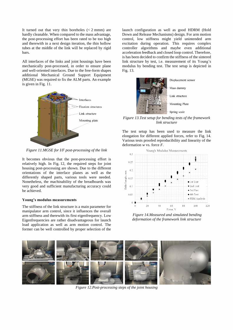
All interfaces of the links and joint housings have been
mechanically post-processed, in order to ensure plane
and well-oriented interfaces. Due to the free-form shapes
additional Mechanical Ground Support Equipment
(MGSE) was required to fix the ALM parts. An example
is given in Fig. 11.
Figure 11.MGSE for I/F post-processing of the link
It becomes obvious that the post-processing effort is
relatively high. In Fig. 12, the required steps for joint
housing post-processing are shown. Due to the different
orientations of the interface planes as well as the
differently shaped parts, various tools were needed.
Nonetheless, the machinability of the breadboards was
very good and sufficient manufacturing accuracy could
be achieved.
Young’s modulus measurements
The stiffness of the link structure is a main parameter for
manipulator arm control, since it influences the overall
arm stiffness and therewith its first eigenfrequency. Low
Eigenfrequencies are rather disadvantageous for launch
load application as well as arm motion control. The
former can be well controlled by proper selection of the
launch configuration as well as good HDRM (Hold
Down and Release Mechanisms) design. For arm motion
control, low stiffness might yield unintended arm
excitation during operation. This requires complex
controller algorithms and maybe even additional
acceleration feedback and closed loop control. Therefore,
is has been decided to confirm the stiffness of the sintered
link structure by test, i.e. measurement of its Young’s
modulus by bending test. The test setup is depicted in
Fig. 13.
Figure 13.Test setup for bending tests of the framework
link structure
The test setup has been used to measure the link
elongation for different applied forces, refer to Fig. 14.
Various tests proofed reproducibility and linearity of the
deformation w vs. force F.
Figure 14.Measured and simulated bending
deformation of the framework link structure
Figure 12.Post-processing steps of the joint housing
Using the above shown data, the Young`s modulus E
could be determined applying the bending line equation:
𝐸 =𝐹/2∙𝑙2−𝐹 6⁄ ∙𝑙3
𝐼𝐴∙𝑤(𝑙) (1)
For the required geometric properties, namely length l
and second moment of area IA, mean values have been
extracted from the CAD (Computer Aided Design)
model of the link. Therewith, a mean Young’s modulus
of 57.6 GPa has been determined. This is approximately
20% less than the given minimum value of 70 GPa from
[6].
For FE model evaluation, the measured Young’s
modulus has been used to simulate the deformation of the
link structure when applying a bending force. The results
are depicted in Fig 14 (indicated by black crosses). It can
be seen that the simulation slightly overestimates the link
stiffness, which is a systematic failure in finite element
modelling. The calculated deformation is approximately
25% lower than the simulated one. Main reason for the
deviation is the complex geometry of the link, which has
only be considered via mean geometric properties in
Eq. 1. Therefore, the simulation results are considered
reasonable for further structure mechanical analysis of
the system.
Since the measured Young’s modulus is lower than the
value given in the data sheet, the FE model of the link
shown in Fig. 5 (bottom) has been updated and the
eigenfrequency was recalculated to be 132 Hz (144 Hz it
was with the value from the data sheet). This slightly
reduces the benefit of the framework structure when
compared to conventional solid bars, but still provides
good justification for the chosen design.
Sine Vibration testing
To further justify the framework design of the links, sine
vibration tests have been carried out to do a resonance
survey. The test set-up is depicted in Fig 15.
Figure 15.Test setup for sine vibration tests of the
framework link structure
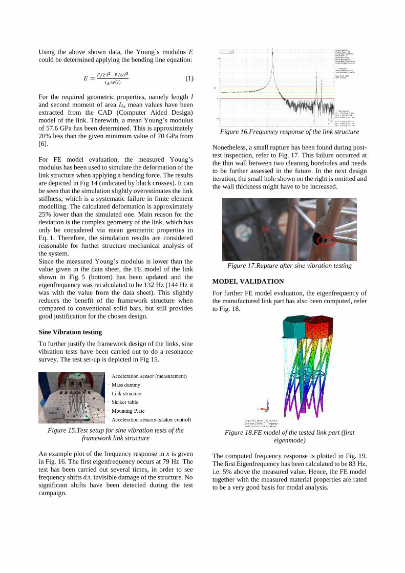
An example plot of the frequency response in x is given
in Fig. 16. The first eigenfrequency occurs at 79 Hz. The
test has been carried out several times, in order to see
frequency shifts d.t. invisible damage of the structure. No
significant shifts have been detected during the test
campaign.
Figure 16.Frequency response of the link structure
Nonetheless, a small rupture has been found during post-
test inspection, refer to Fig. 17. This failure occurred at
the thin wall between two cleaning boreholes and needs
to be further assessed in the future. In the next design
iteration, the small hole shown on the right is omitted and
the wall thickness might have to be increased.
Figure 17.Rupture after sine vibration testing
MODEL VALIDATION
For further FE model evaluation, the eigenfrequency of
the manufactured link part has also been computed, refer
to Fig. 18.
Figure 18.FE model of the tested link part (first
eigenmode)
The computed frequency response is plotted in Fig. 19.
The first Eigenfrequency has been calculated to be 83 Hz,
i.e. 5% above the measured value. Hence, the FE model
together with the measured material properties are rated
to be a very good basis for modal analysis.
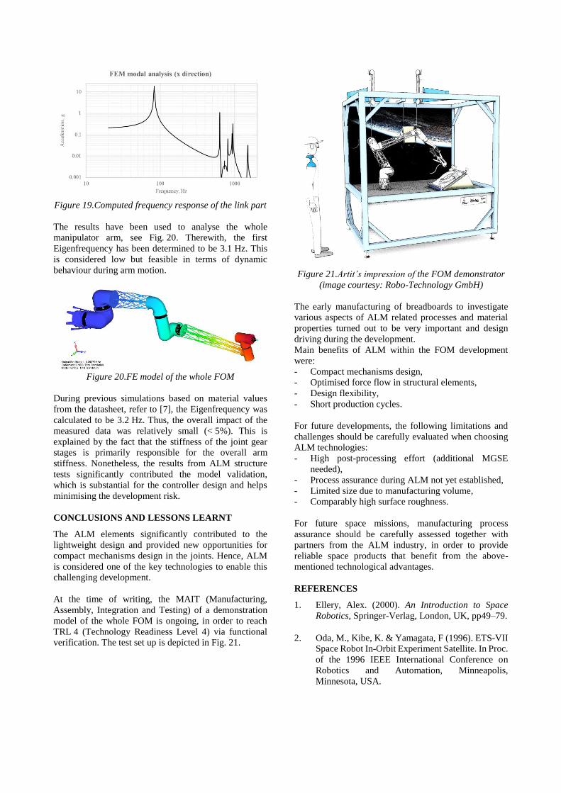
Figure 19.Computed frequency response of the link part
The results have been used to analyse the whole
manipulator arm, see Fig. 20. Therewith, the first
Eigenfrequency has been determined to be 3.1 Hz. This
is considered low but feasible in terms of dynamic
behaviour during arm motion.
Figure 20.FE model of the whole FOM
During previous simulations based on material values
from the datasheet, refer to [7], the Eigenfrequency was
calculated to be 3.2 Hz. Thus, the overall impact of the
measured data was relatively small (< 5%). This is
explained by the fact that the stiffness of the joint gear
stages is primarily responsible for the overall arm
stiffness. Nonetheless, the results from ALM structure
tests significantly contributed the model validation,
which is substantial for the controller design and helps
minimising the development risk.
CONCLUSIONS AND LESSONS LEARNT
The ALM elements significantly contributed to the
lightweight design and provided new opportunities for
compact mechanisms design in the joints. Hence, ALM
is considered one of the key technologies to enable this
challenging development.
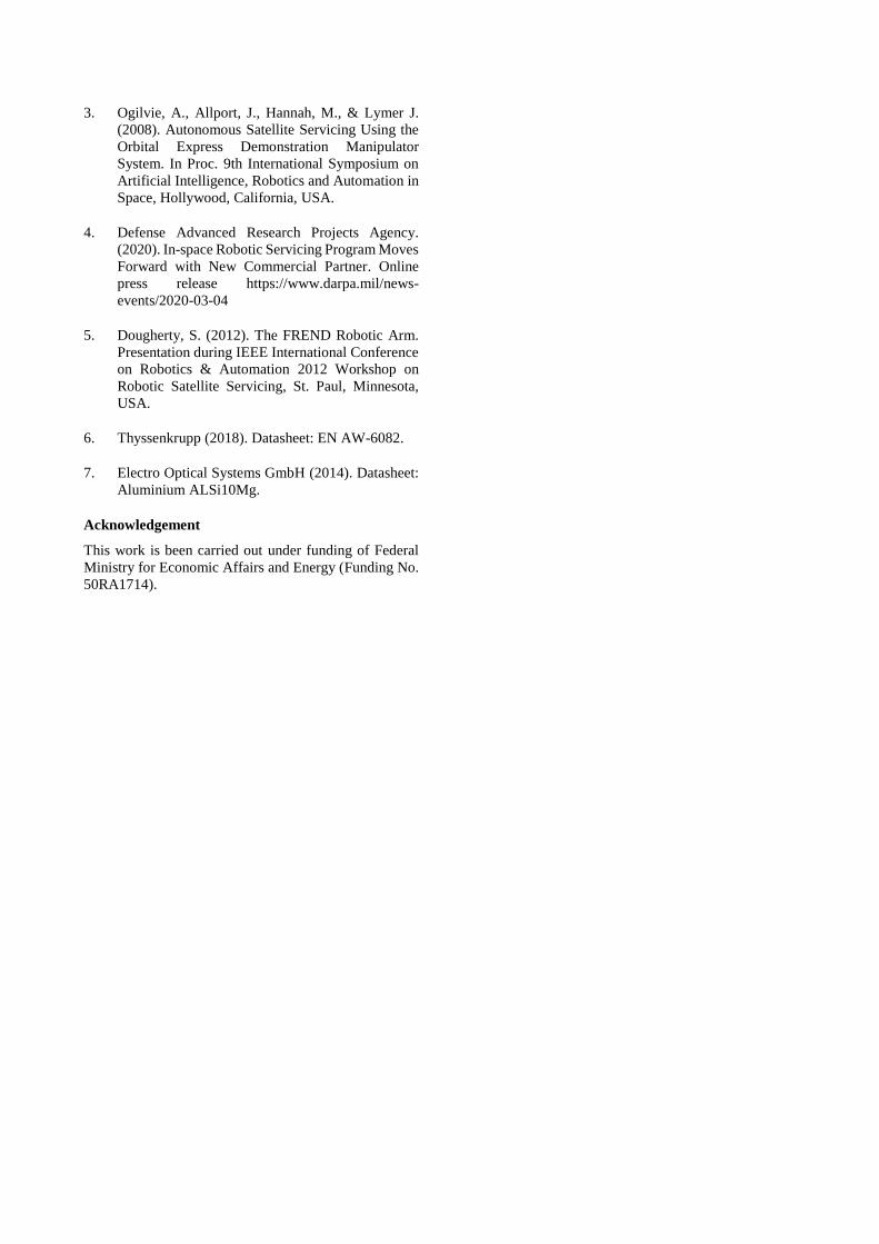
At the time of writing, the MAIT (Manufacturing,
Assembly, Integration and Testing) of a demonstration
model of the whole FOM is ongoing, in order to reach
TRL 4 (Technology Readiness Level 4) via functional
verification. The test set up is depicted in Fig. 21.
Figure 21.Artit’s impression of the FOM demonstrator
(image courtesy: Robo-Technology GmbH)
The early manufacturing of breadboards to investigate
various aspects of ALM related processes and material
properties turned out to be very important and design
driving during the development.
Main benefits of ALM within the FOM development
were:
- Compact mechanisms design,
- Optimised force flow in structural elements,
- Design flexibility,
- Short production cycles.
For future developments, the following limitations and
challenges should be carefully evaluated when choosing
ALM technologies:
- High post-processing effort (additional MGSE
needed),
- Process assurance during ALM not yet established,
- Limited size due to manufacturing volume,
- Comparably high surface roughness.
For future space missions, manufacturing process
assurance should be carefully assessed together with
partners from the ALM industry, in order to provide
reliable space products that benefit from the above-
mentioned technological advantages.
REFERENCES
1. Ellery, Alex. (2000). An Introduction to Space
Robotics, Springer-Verlag, London, UK, pp49–79.
2. Oda, M., Kibe, K. & Yamagata, F (1996). ETS-VII
Space Robot In-Orbit Experiment Satellite. In Proc.
of the 1996 IEEE International Conference on
Robotics and Automation, Minneapolis,
Minnesota, USA.
3. Ogilvie, A., Allport, J., Hannah, M., & Lymer J.
(2008). Autonomous Satellite Servicing Using the
Orbital Express Demonstration Manipulator
System. In Proc. 9th International Symposium on
Artificial Intelligence, Robotics and Automation in
Space, Hollywood, California, USA.
4. Defense Advanced Research Projects Agency.
(2020). In-space Robotic Servicing Program Moves
Forward with New Commercial Partner. Online
press release https://www.darpa.mil/news-
events/2020-03-04
5. Dougherty, S. (2012). The FREND Robotic Arm.
Presentation during IEEE International Conference
on Robotics & Automation 2012 Workshop on
Robotic Satellite Servicing, St. Paul, Minnesota,
USA.
6. Thyssenkrupp (2018). Datasheet: EN AW-6082.
7. Electro Optical Systems GmbH (2014). Datasheet:
Aluminium ALSi10Mg.
Acknowledgement
This work is been carried out under funding of Federal
Ministry for Economic Affairs and Energy (Funding No.
50RA1714).