Advanced Simulation for Additive Manufacturing: Meeting ...
27
ORNL/TM-2015/324 Approved for public release. John A. Turner Sudarsanam Suresh Babu Craig Blue July 2015 Advanced Simulation for Additive Manufacturing: Meeting Challenges Through Collaboration Workshop Report for the Advanced Manufacturing Office U.S. DOE Office of Energy Efficiency & Renewable Energy
Transcript of Advanced Simulation for Additive Manufacturing: Meeting ...

ORNL/TM-2015/324
Approved for public release.
John A. Turner
Sudarsanam Suresh Babu
Craig Blue
July 2015
Advanced Simulation for Additive Manufacturing: Meeting Challenges Through Collaboration Workshop Report for the Advanced Manufacturing Office U.S. DOE Office of Energy Efficiency & Renewable Energy

DOCUMENT AVAILABILITY
Reports produced after January 1, 1996, are generally available free via US Department of Energy (DOE) SciTech Connect.
Website http://www.osti.gov/scitech/
Reports produced before January 1, 1996, may be purchased by members of the public from the following source:
National Technical Information Service
5285 Port Royal Road
Springfield, VA 22161
Telephone 703-605-6000 (1-800-553-6847)
TDD 703-487-4639
Fax 703-605-6900
E-mail [email protected]
Website http://www.ntis.gov/help/ordermethods.aspx
Reports are available to DOE employees, DOE contractors, Energy Technology Data Exchange representatives, and International Nuclear Information System representatives from the following source:
Office of Scientific and Technical Information
PO Box 62
Oak Ridge, TN 37831
Telephone 865-576-8401
Fax 865-576-5728
E-mail [email protected]
Website http://www.osti.gov/contact.html

ORNL/TM-2015/324
Computer Science and Mathematics Division (CSMD)
Manufacturing Demonstration Facility (MDF)
Advanced Simulation for Additive Manufacturing: Meeting Challenges Through Collaboration
Workshop Report for the
U.S. Department of Energy’s Advanced Manufacturing Office (AMO)
in the Office of Energy Efficiency & Renewable Energy
John A. Turner (ORNL)
Sudarsanam Suresh Babu (UTK, ORNL)
Craig Blue (ORNL)
Date Published:
July 2015

Prepared by
OAK RIDGE NATIONAL LABORATORY
Oak Ridge, TN 37831-6283
managed by
UT-BATTELLE, LLC
for the
US DEPARTMENT OF ENERGY
under contract DE-AC05-00OR22725

iii
CONTENTS
CONTENTS ........................................................................................................................................................................................ iii
1. Plenary Session ..................................................................................................................................................................... 2
2. Breakout report summaries ........................................................................................................................................... 4
2.1 Heat Transfer and Particle Properties .......................................................................................................... 4
2.1.1 Predictive Simulation of Melt Pools ............................................................................................... 5
2.1.2 Powder properties .................................................................................................................................. 6
2.1.3 Thermophysical properties, including non-equilibrium effects ...................................... 6
2.1.4 Surface Finish Prediction .................................................................................................................... 7
2.2 Residual Stress and Mesoscale Simulations (RSMS) .............................................................................. 7
2.2.1 Predicting Complex Microstructure Evolution in AM Processes ..................................... 8
2.2.2 Predicting Residual Stress and Distortion .................................................................................. 9
2.2.3 Uncertainty Quantification and Optimization ........................................................................ 10
2.3 Topology Optimization and Crosscutting Computational Issues (TOCC) ................................. 11
2.3.1 Technology Enhancement of Topology Optimization ........................................................ 12
2.3.2 Including AM Process in Design .................................................................................................... 12
2.3.3 Improve Usability of Topology Optimization Tools ............................................................ 13
2.3.4 Access and Interoperability of Research .................................................................................. 13
2.3.5 Market Development for Commercial Software Vendors................................................. 14
3. Integration Discussion and Next Steps ................................................................................................................... 15
Appendix A. Predictive Capability Roadmap for Additive Manufacturing ...................................................... 17
Appendix B. Workshop agenda ............................................................................................................................................ 18
Appendix C. Attendees .............................................................................................................................................................. 20
1
A D VA NC ED S I M UL A TI O N F O R A D D I TI V E M A N U FA C T UR I N G:
M E E T I N G C H A L L E N G E S T H R O U G H C O L L A B O R A T I O N
WORKSHOP REPORT FOR THE U.S. DOE ADVANCED MANUFACTURING OFFICE OFFICE OF ENERGY EFFICIENCY & RENEWABLE ENERGY On November 4-5, 2014, a workshop was organized at the Manufacturing Demonstration Facility (MDF) at Oak Ridge National Laboratory to discuss challenges and opportunities for advanced modeling and simulation to augment and accelerate progress in the rapidly developing field of additive manufacturing (AM). It is widely-acknowledged that the rapid advances in AM have the potential to dramatically transform the manufacturing industry. However, improvements in performance and consistency of material properties, optimized process control, reduced tolerances, and new materials and processes are required in order for AM to meet performance, quality and cost targets, along with increased manufacturing speed.
There were 61 attendees, representing private industry, academia, DOE national laboratories, and other U.S. government agencies. Approximately one-third of the participants were from industry, and represented both practitioners using (or planning to use) AM in production and independent software vendors (ISVs) developing and deploying tools for modeling and simulation of AM processes.
This workshop followed previous meetings such as the workshop in December of 2012 at NIST in Gaithersburg, MD. While that workshop was focused on measurement science for AM, few of the barriers identified were a lack of validated physics- and properties-based predictive models for AM, with a recommendation to aggressively address that gap. The present workshop at MDF focused on this unresolved issue. The topics including topology optimization, heat and mass transfer, solidification, solid-state transformations, residual stress and distortion were discussed. This report provides the summary of the workshop topics, discussions and future directions with reference to advanced simulations for additive manufacturing.

2
1. PLENARY SESSION
This workshop was co-organized by John Turner, Group Leader for the Computational Engineering and Energy Sciences Group in the Computer Science and Mathematics Division at ORNL and Chief Computational Scientist for the Consortium for Advanced Simulation of Light-Water Reactors (CASL), Sudarsanam Suresh Babu, University of Tennessee Governor’s Chair for Advanced Manufacturing in the Department of Mechanical, Aerospace, and Biomedical Engineering, and Craig Blue, Director of the Manufacturing Demonstration Facility at ORNL. The workshop opened with a welcome by Dr. Martin Keller, Associate Laboratory Director for the Energy and Environmental Sciences Directorate at ORNL.
Blake Marshall, lead for Additive Manufacturing Technologies in the DOE/EERE Advanced Manufacturing Office (AMO), then provided an overview of AMO activities, priorities, and the charge for the workshop. The overarching question for the workshop was as following.
How do we best utilize advanced modeling and high-performance computing (HPC) to address key challenges and opportunities in order to realize the full potential of additive manufacturing?
The charge was followed by presentations discussing the potential for AM and current activities and priorities from three perspectives: • Wayne King, Director of the Accelerated Certification of Additively Manufactured Metals
Initiative at LLNL, presented “Science-based Additive Manufacturing for NNSA Missions”, summarizing on-going activities in the DOE National Nuclear Security Administration (NNSA).
• John Wilczynski, Deputy Director of Technology Development for the national Center for Defense Manufacturing and Machining (NCDMM) provided an overview of “America Makes”, one of the National Network for Manufacturing Innovation (NNMI) institutes, a public/private partnership also known as the National Additive Manufacturing Innovation Institute (NAMII).
• David Dietrich, Additive Metals Technology Lead for Boeing Research and Technology discussed design and simulation needs from the industry perspective.
• Ryan Dehoff, member of the Materials Processing & Manufacturing Group at ORNL concluded the plenary session by showing recent results demonstrating the ability to locally control the grain structure and hence, properties of additively-manufactured metal parts using the ARCAM electron beam melting (EBM) system.
The plenary session concluded with a discussion of the logistics for the remainder of the workshop, which was organized as three breakout groups, each encompassing two related areas.
1. Heat Transfer and Particle Properties (HTPP), led by T. DebRoy (Penn. State Univ.) and
Marianne Francois (LANL). Sreekanth Pannala of ORNL facilitated discussions on the following areas:
a. heat transfer, melting, and solidification b. particle-resolved simulations for effective properties
2. Residual Stress and Mesoscale Simulations (RSMS), led by Robert Ferencz (LLNL) and Paul Mason (Thermo-Calc). B. Radhakrishnan (Rad) of ORNL facilitated discussions on the following topics:
a. thermomechanics and residual stress b. mesoscale simulations for microstructure

3
3. Topology Optimization and Crosscutting Computational Issues (TOCC), led by Ted Blacker (SNL) and Suzy Tichenor (ORNL). David Dietrich of Boeing facilitated discussions on the following areas:
a. topology optimization b. crosscutting computational science (multiscale methods, adaptive mesh refinement,
code integration, workflow, uncertainty quantification, etc.)
Workshop participants were free to choose whichever group most closely matched interests and expertise.
The overarching question posed to the breakout groups was as follows:
What are the key challenges of additive manufacturing to which modeling and simulation can contribute solutions, and what will it take to meet these challenges?
For each challenge identified: • Is this challenge specific to one process, a subset of processes, or is it common across all additive
manufacturing processes? • What are current approaches, tools, and methods being used? • What are the shortcomings of current approaches, tools, and methods? What research and/or
development, whether physics or computational / numerical (including an estimate of investment required), is needed?
• What is the importance / priority compared to other challenges? • What computational resources are required, both for current approaches and to fully address? • Can a test problem (or set of test problems) be defined to gauge community progress toward
meeting this challenge? If yes, then a problem (or set of problems) should be proposed.

4
2. BREAKOUT REPORT SUMMARIES
Following breakout discussions, each group summarized their findings for the group through brief presentations to, and follow-up Q&A with, all the workshop participants.
2.1 HEAT TRANSFER AND PARTICLE PROPERTIES
This section primarily focused on metal additive manufacturing processes. It is well known that the internal microstructure, properties and performance of a material is determined during its processing. Therefore it is important to understand the thermal history, cooling rates, phase transformation, and resulting residual stress associated to a given process.
Additive manufacturing processes for metals could be grouped into two broad categories: (1) powder bed or (2) powder or wire-directed energy deposition. Regardless, there are overarching key challenges that have been identified for metal additive manufacturing processes. They are listed below.
Key Challenges • Feedstock properties - effect of powder characteristics (size, morphology, packing coordination,
chemical composition, oxidation, internal porosity, etc.) on effective properties (thermal conductivity, specific heat, emissivity, absorptivity, friction, etc.)
• Thermophysical properties (surface tension, conductivity, absorption, viscosity, specific heat, etc.) from melting point to boiling point. Also non-equilibrium effects (free energy, solidification, and phase transformation).
• Processing: ○ Evaporation (recoil pressure, defect formation, key-hole formation) ○ Selective vaporization of volatile alloying elements ○ Effect of melt pool topology on solidification mode ○ Heat source characteristics (or type – laser vs. E-beam) and parameters
Primary Modeling and Simulation Goals • Prediction of melt pool geometry, temperature distribution, and interfacial dynamics. • Viscoplastic behavior near melting. • Determine and quantify relationship between process irregularities and macroscopic defects.
Current Approaches • For continuum-level simulation of heat transfer, melting and solidification, free surface flow, and
thermal stress, multiple finite volume (FV), finite element (FE), and finite difference (FD) codes are in use, including: ○ Commercial - COMSOL, Abaqus ○ Lab - Truchas (developed at LANL, used by LANL, ORNL, and GE), Sierra (SNL), Diablo
(LLNL) ○ University and Small business - SAMP (OSU and Applied Optimization), Pan Computing, LLC
• Particle-resolved simulations: ○ ALE3D (LLNL) ○ MFIX (ORNL)
• Microstructure (see also Section 2.2) ○ phase field (MICRESS and other codes)
• Process mapping/ models (developed by equipment makers and universities) ○ Carnegie Mellon University (Tolemaic Systems)

5
Shortcomings/ Gaps / Research Needs • Coupling across length scales, from microstructure to part-scale • Coupling across time scales • Need to couple free surface fluid flow and model melt pool dynamics (current models are highly
focused on heat transfer, phase change, and residual stress, fluid flow is often times not considered)
• Nucleation and growth models • Uncertainties in data properties and sensitivities of results to those uncertainties • Validation with in-situ monitoring • Fast tools/models derived from simulations and experimental data: reduced order models
and/or process models. These models will run fast (less than a second). They are derived through machine learning algorithms/statistical methods based on a set of data obtained from simulations and experiments).
Detailed analysis of four specific challenges follows.
2.1.1 Predictive Simulation of Melt Pools
Challenge Predict heat and mass transfer and fluid flow efficiently, in order to predict melt pool characteristics for AM and multiple layers (continuum scale) for spatiotemporal variations of temperature, solidification parameters and geometry
Current Approach (availability)
Welding capability available but not adaptable to AM yet
Gap(s) Heat conduction model only, leading to overestimation of cooling rate; inadequate treatment of relevant AM phenomena; time-consuming simulations
Goal Efficient calculation of heat and mass transfer and fluid flow for specific AM condition
Near-term (1-3 yrs) Heat transfer, melting and solidification, and maybe fluid flow (applying existing tools – COTS, Truchas, Sierra, Aria, ALE3D); Improve free surface predictions (identify key parameters); Scale-specific model (micro, meso, and macro); Uncertainty quantification and sensitivity;
Mid-term (2-5 yrs) Mushy zone, surface tension effects, multilayer effects; User friendly; Better material properties/database; Coupling across some of the scales;
Long-term (10 yrs) High fidelity models coupled with particle scale features (coupling all the scales – efficient upscaling); Fast reduced models; Fast; User-friendly for different process (EBM, SLM, etc.)
Benchmark / Test problem(s)
Standard material and make prototype problems over parameter space (DOE); Predict properties (incl. surface finish) within certain error bars with certain confidence limits; Evaluation of different models;
Expected impact Mapping out processing space and specify bounds and property-processing relationships for various materials and machine uncertainties; Impact process optimization for various propulsion devices;
6
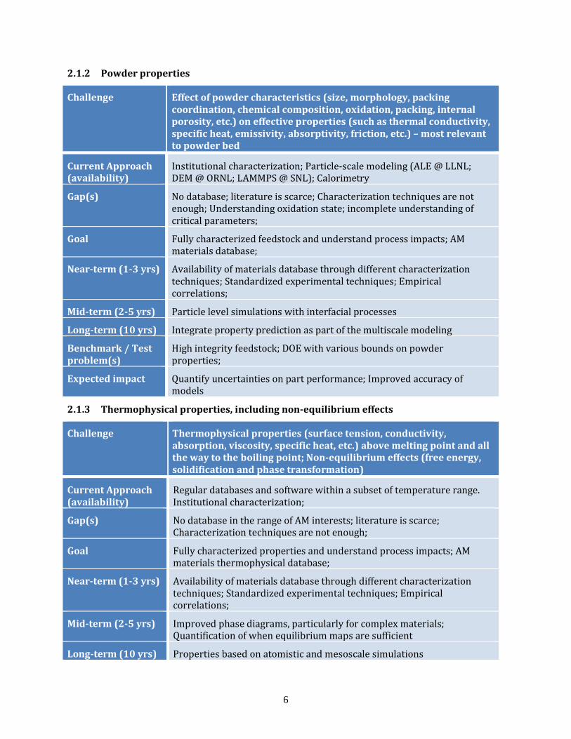
2.1.2 Powder properties
Challenge Effect of powder characteristics (size, morphology, packing coordination, chemical composition, oxidation, packing, internal porosity, etc.) on effective properties (such as thermal conductivity, specific heat, emissivity, absorptivity, friction, etc.) – most relevant to powder bed
Current Approach (availability)
Institutional characterization; Particle-scale modeling (ALE @ LLNL; DEM @ ORNL; LAMMPS @ SNL); Calorimetry
Gap(s) No database; literature is scarce; Characterization techniques are not enough; Understanding oxidation state; incomplete understanding of critical parameters;
Goal Fully characterized feedstock and understand process impacts; AM materials database;
Near-term (1-3 yrs) Availability of materials database through different characterization techniques; Standardized experimental techniques; Empirical correlations;
Mid-term (2-5 yrs) Particle level simulations with interfacial processes
Long-term (10 yrs) Integrate property prediction as part of the multiscale modeling
Benchmark / Test problem(s)
High integrity feedstock; DOE with various bounds on powder properties;
Expected impact Quantify uncertainties on part performance; Improved accuracy of models
2.1.3 Thermophysical properties, including non-equilibrium effects
Challenge Thermophysical properties (surface tension, conductivity, absorption, viscosity, specific heat, etc.) above melting point and all the way to the boiling point; Non-equilibrium effects (free energy, solidification and phase transformation)
Current Approach (availability)
Regular databases and software within a subset of temperature range. Institutional characterization;
Gap(s) No database in the range of AM interests; literature is scarce; Characterization techniques are not enough;
Goal Fully characterized properties and understand process impacts; AM materials thermophysical database;
Near-term (1-3 yrs) Availability of materials database through different characterization techniques; Standardized experimental techniques; Empirical correlations;
Mid-term (2-5 yrs) Improved phase diagrams, particularly for complex materials; Quantification of when equilibrium maps are sufficient
Long-term (10 yrs) Properties based on atomistic and mesoscale simulations

7
Benchmark / Test problem(s)
Standardized interfaces to data and knowledge base.
Expected impact Quantify uncertainties on part performance; Improved accuracy of models
2.1.4 Surface Finish Prediction
Challenge Controllable Surface Finish
Current Approach (availability)
Very limited (ALE3D); Molecular dynamics for small scale roughness;
Gap(s) Currently limited to several hundred particles for powder bed simulation; overly-simplistic direct energy deposition models and powder fed processes (e.g. in most current welding simulations the free-surface is assumed flat and there is a lack of simulation/modeling of particles falling into melt pool)
Goal Predict surface finish (roughness, particle-level, low frequency)
Near-term (1-3 yrs) Build on existing scales; Correlation between process variables and profilometry
Mid-term (2-5 yrs) Coupling across heat transfer & fluid flow and particle-level simulations, free surface flow instabilities, etc.
Long-term (10 yrs) Optimization of surface finish
Benchmark/Test problem(s)
V&V; Profilometry for various prototype problems
Expected impact Process maps for desired finish
2.2 RESIDUAL STRESS AND MESOSCALE SIMULATIONS (RSMS)
Key Goals / Challenges • Predict evolving microstructures and understand their effect on performance properties. This
includes understanding the relationship between properties for bulk materials used for AM and properties for AM feedstock (powders, wire, etc.).
• Predict fabricated geometry and residual stress. • Fully understand the interconnections between the above. • Simulation across time scales (local material transformation vs. overall part fabrication),
including the effects of the cyclic nature of AM processes. • Characterizing process parameters that are key modeling inputs • Adequate and appropriate validation data • Material characterizations to support modeling • Quantification of uncertainties • A spectrum of simulation tools that trade off fidelity and computational efficiency in order to
serve different user needs.
Detailed analysis of three specific challenges follows.

8
2.2.1 Predicting Complex Microstructure Evolution in AM Processes
Current Approaches: For microstructure simulations, the approach has relied mainly on computational thermodynamics and kinetics models that have been used in the past for conventional solidification and thermo-mechanical processing of structural alloys. Commercial software packages include Thermocalc, Dictra, and JMatPro. Specific techniques include analytical modeling using JMAK or simultaneous transformation models. There exists open source software for predicting microstructure and property of metals subjected to traditional manufacturing1. Commonly used mesoscale approach for simulating microstructure evolution is the phase field method with linkages to the thermodynamics and kinetic databases listed above. However, the use of the phase field method for AM is emerging because of the difficulties associated with the extreme processing conditions that give rise to non-equilibrium effects.
Limitations: There are many limitations that prevent the accurate prediction of microstructures in AM processes. These include (1) inability to accurately predict the location-specific thermal history in AM builds (2) extremely high heating and cooling rates through phase transformation temperatures leading to potential deviation from equilibrium resulting in the formation of metastable phases and (4) spatial and temporal gradients in temperature. Therefore, methods that rely on equilibrium thermodynamic database are not adequate. There is also significant challenge in developing kinetic database under non-equilibrium situations described above. There is also a significant coupling between transient stress and nucleation of phases in solid-state transformations that is a particular challenge for microstructure modeling in AM parts because of the inability to predict the transient stresses.
Path Forward: It is necessary to develop mesoscale models that are informed by lower length scale models in order to carry the relevant physics associated with potential non-equilibrium and their effects on thermodynamics and kinetics. These different mesoscale models should be validated / assessed using benchmark experiments. Failure to predict benchmark experiments will identify the gaps in the mesoscale model and provide guidance for model refinement. One benchmark experiment is Gleeble thermo-mechanical simulation of microstructures under repeated thermal cycles experienced under AM conditions. These experiments will not capture spatial gradients and associated residual stress effects, but will help adequately address non-equilibrium effects and repeated heating on microstructure evolution. The effect of microstructure on part performance is different for different material systems and processes. Therefore, the need for a predictive microstructure model could be user-dependent. In this respect, it is necessary to identify critical process parameters and material systems that require predictive microstructure models.
Challenge Predicting complex microstructure evolution from AM processes
Expected Impact (ROI)
Increase confidence and speed up certification
Current Approach Correlation to exp. data; analytical & (semi-) empirical models; expensive ‘first principles’ simulations
Gap(s) Experimental data to build/validate models; science of fundamental relationships; Ability to model dynamic, non-equilibrium phase evolution and microstructure
Goal Ability to predict material performance properties dependent on local microstructure; Support predictive location-specific control of properties

9
Near-term (1-3 yrs) Benchmarking current tools under AM process conditions
Mid-term (2-5 yrs) Non-equilibrium thermodynamics, kinetics, nucleation, coupling between residual stress and variant/phase selection, effects of temporal and spatial gradients in temperature and concentration
Long-term (10 yrs) Predict processing-microstructure-property linkages using integrated multi-scale modeling of microstructure and micromechanics
Benchmark / Test Problem(s)
Need ensemble of benchmarks for targeted processes and material systems. Design Quantity of Interest TBD, e.g., minimal material properties.
Compute the “DOE” printing with microstructure control.
2.2.2 Predicting Residual Stress and Distortion
Current Approaches: Current modeling approaches and modeling tools employed in predicting residual stress and distortion in AM are primarily the ones that have been used in welding. These include thermal and mechanical simulations using commercial finite element packages such as ABAQUS, ANSYS. More recently computationally efficient codes by virtue of dynamic re-meshing and improved algorithms such as SIM3D are being used in AM process simulations. SYSWELD is another finite element package that has been widely used in modeling the Laser Engineered Net Shaping (LENS) process. In addition there are finite element codes developed at various National Laboratories such as TRUCHAS (LANL), SIERRA (SNL) are currently being considered for simulating powder bed based metal additive manufacturing processes.
Limitations: Although they have been used successfully in welding applications, there are additional challenges associated with simulating the residual stress in AM processes because of the size of the simulation, the lack of a quasi-steady state, layer-to-layer variation in cross-section and other unknowns related to material physics at lower length scales. In addition to large simulation size there is also a challenge posed by the long simulation time. It is necessary to have models that can quantify the effect of heat source dynamics, part geometry and part orientation during AM on residual stress. Currently there are no models that can quantify the potential link between residual stress and microstructure. Other important aspect of modeling residual stress that are currently not possible include the prediction of distortion in AM parts as a function of process parameters so that the target part shape can be designed a priori to account for distortion, and prescribing a post-build heat treatment to relieve residual stresses.
Path Forward: A key missing piece in predicting the residual stress during AM is the constitutive behavior of the material at the build temperatures. It is necessary to develop such a database either through experiments or predict using micromechanical simulations. In order for the micromechanical model to be predictive, it is necessary to use a realistic input microstructure at temperature, which is already identified as a challenge. In this regard, it is necessary to develop a repository for existing / under-development microstructure models that can be integrated with micro-mechanical models to provide material property input to residual stress calculations. Experimental programs to develop realistic high temperature mechanical property data should be pursued. It is necessary to resort to high performance computing with efficient solvers and dynamic re-meshing capabilities to handle large simulation volume and simulation time. One approach that has recently been pursued is the equivalent plasticity model to predict distortion in large-scale structures. Finally, it is necessary to build a modeling platform specifically for AM because the existing tools developed for weld residual stress prediction were not developed for AM and are too slow for AM applications. Also, it is necessary to develop a suit of codes with provision

10
for data exchange between codes. Experimental approach for measuring residual stress and distortion should include neutron diffraction / imaging and the use of physical surrogates during fabrication such as cantilevers.
Challenge Predict as-fabricated configuration (including support structures) to assess distortion and other product fitness Quantities of Interest
Expected Impact (ROI)
Enable broader design space, support process mitigations, accelerate process ID, reduce product variability and scrap
Current Approach Thermo-mechanical FEA with various tools and modeling strategies
Gap Limited material models and/or data characterization for range of process temperatures; modeling and algorithmic strategies increasing computational throughput; interaction/integration with microstructure evolution models with inputs from melt-pool modeling; integration with CAE workflow.
Goal Timely prediction of as-fabricated configuration to assess distortion, properties distribution, and supporting certification; Robust forward modeling to support design and process optimization.
Near-term (1-3 yrs) Benchmarking current tools under AM process conditions; Literature review
Mid-term (2-5 yrs) Develop models/tools for high-value gaps; benchmark more complex geometries
Long-term (10 yrs) Total workflow integration - integrate topology optimization with physically based modeling of processing-structure-property linkages. Support in-process control.
Benchmark / Test Problem(s)
Progressive geometric complexity. Design in-situ measurement features. NAFEMS or other community interests?
2.2.3 Uncertainty Quantification and Optimization
Current Approaches: Current approach is almost entirely based on experiments. Large trial-and-error approach is based on systematic variation of processing parameters and material composition to meet the desired geometry and part performance.
Limitations: Because of the lack of predictive process-microstructure-property model current approach that relies mainly on experimental data results in excessive material wastage, increased processing cost and slow production rate.
Path Forward: The long-term goal is to fully integrate predictive processing-microstructure-property models with part geometry and layer design to minimize the scatter in mechanical properties within the build, as well as to minimize the anisotropy in mechanical properties to facilitate rapid certification of AM parts. However, since such models will take a long time to develop, the short-term goal would be to develop alternative approaches based on heuristic models such as artificial neural networks/ machine learning using experimental data to identify critical process and material parameters that influence build properties. In the long term, the modeling/experimental effort should focus on the following developments that are directly responsible for the uncertainty:

11
• Realistic boundary conditions including process and material characteristics • Temperature dependent thermo-physical properties • Understand the influence of dissolved oxygen on material properties • Formation of defects including cracking due to residual stress • Non-equilibrium effects on microstructure • Modeling of inter-layer shrinkage and delamination • Particle level modeling
Challenge Dealing with the range of processes, variability of materials and resulting properties
Expected Impact (ROI)
Faster, higher-confidence process ID; more flexible product design; lower costs
Current Approach Experimental investigations of sensitivities; costs limit exploration. Limited use of in-process data.
Gap Limited/emerging mod/sim support to provide tractable forward modeling capabilities for use within optimization and UQ engines.
Goal Bound uncertainties to support design and manufacturing decisions; Minimize the resulting product variability; Support more rapid certification of material
Near-term (1-3 yrs) Literature review / rank & consolidate exp. data / exp. data standard?
Computational DOI to assess gaps/sensitivities. Modeling gaps wkshp?
Mid-term (2-5 yrs) Exp. studies and data analysis; heuristic meta-models & design rules
Long-term (10 yrs) Integrated modeling approach with UQ for design and qualification (can be ensemble of tools)
Benchmark / Test Problem(s)
Need ensemble of benchmarks for targeted processes and material systems. Designer Quantity of Interest TBD, e.g., minimal material properties.
A general remark about modeling effort is applicable to all three challenges. Identification of critical outputs should be targeted for each subset of users so that the models can be efficiently developed to allow assumptions and use hidden layers that won’t obscure the critical inputs or outputs. This requires knowledge of industry needs for proper designs (what knowledge is critical for a part designer) so that a useful, simpler model can be created for the end user.
2.3 TOPOLOGY OPTIMIZATION AND CROSSCUTTING COMPUTATIONAL ISSUES (TOCC)
AM is not about making old designs a new way – it is about making new designs a new way. The potential of AM is fully realized when the design space changes to take advantage of the possible complexity. Topology optimization (i.e. function-based design) is uniquely poised to maximize this impact.
Early impact is critical. To move this technology forward, we must show early impact with new topology optimization tools. This will create pull to sustain continued technology development, sophistication and ultimate impact.
Detailed analysis of five specific challenges follows.

12
2.3.1 Technology Enhancement of Topology Optimization
Challenge Topology optimization (TO) technology must be matured.
Expected Impact (ROI)
Design impact using rapid iterations, effective interactive design guidance during optimization and powerful physics and optimization algorithm development and integration.
Current Approach Initial codes are relatively simplistic in terms of meshing, optimization algorithms and included physics.
Gap Advanced physics, higher-order optimization, geometric tools, speed, interaction
Goal Rich physics inclusion within the optimization, higher-order optimization algorithms and powerful topology editing and interaction technologies, conversion to NURBS.
Near-term (1-3 yrs) Robust multi-load cases for elasto-statics, thermal, and fluid flow. Control with standard optimization algorithms. Basic topology editing tools, high quality STL output.
Mid-term (2-5 yrs) Inclusion of multi-physics, contact, transient conditions and non-linear materials. Leverage HPC parallelisms to reduce run times. Control with higher-order optimization algorithms. Advanced topology editing and dynamic interaction during optimizations. Conversion of STL to NURBS.
Long-term (10 yrs) Inclusion of manufacturing simulations to minimize distortions as part of design optimization. Inclusion of UQ (Uncertainty Quantification). Further leverage of HPC. Rich interactive environment with user.
Benchmark / Test Problem(s)
Design of standard shapes incorporating higher physics, optimization, etc.
2.3.2 Including AM Process in Design
Challenge TO must account for the expected AM process
Expected Impact (ROI)
Designs can be predictably manufactured, and processes may be improved.
Current Approach There is no inclusion of the AM process during TO design.
Gap Understanding and adjusting for the limitations and constraints of AM processes is critical to design success. The simulations of residual stress are currently very time consuming. The design does not include the minimization of support materials needed for manufacturing.
Goal The TO design should account for the specific manufacturing process as much as possible.
Near-term (1-3 yrs) Inclusion of general low fidelity models (i.e. rules of thumb) should be provided early on in the optimization. Additional accounting for possible support elimination due to the design would be useful.
Mid-term (2-5 yrs) Enhancement of low fidelity models could be improved (speed and

13
physics) and included.
Long-term (10 yrs) High fidelity models are directly included in the optimization. They are fast and robust enough to be useful as part of the optimization.
Benchmark / Test Problem(s)
Simple arch bridge where thermal distortions are expected to be problematic.
2.3.3 Improve Usability of Topology Optimization Tools
Challenge TO packages are difficult to use – time and expertise intensive.
Expected Impact (ROI)
Pervasive use of TO to guide AM (and other) designs. This would facilitate new designs which maximize the power of AM.
Current Approach Only a few experts use TO in design. It is kludgy, disconnected from current engineering processes and less than impactful.
Gap A simple usable interface, easier installs and setup, etc. needed. The power and sophistication of the technology are expected to blossom and the interface to this power will be chasing this complexity.
Goal An interface which can accommodate designer level expertise, be reasonably simple to execute and provide an interactive, steerable design optimization process is required.
Near-term (1-3 yrs) Easier access to existing codes, installation and customization. Attempts to provide a beginning interface with hooks to the optimization process interactions and an ability to post-process TO design output to clean up the STL definitions.
Mid-term (2-5 yrs) Engineer level expertise enabled interface.
Long-term (10 yrs) Designer level expertise enabled interface.
Benchmark / Test Problem(s)
Novice user (researcher to designer) given the package with little instruction can generate a design of a simple structure (table). The metric would be time to completion and difficulty of execution.
2.3.4 Access and Interoperability of Research
Challenge Interoperability (with other COTS tools) and accessibility of research oriented codes (developed by labs and universities) should not be limited.
Expected Impact (ROI)
Early technology pull is necessary to sustain progress in the research. Early impact is essential. Leveraging existing tools for analysis will be essential.
Current Approach Rather isolated independent research efforts and codes.
Gap Technology is sparse, rather inaccessible and doesn’t leverage current tool suites.
Goal Interoperability (with other COTS tools) and accessibility of research oriented codes (developed by labs and universities) will allow early adopters to experiment, gain expertise and provide momentum and

14
feedback loops for the continued development of the technology. This will create innovation across the entire AM industry.
Near-term (1-3 yrs) Early adopters interacting directly with research efforts, using the optimization tools with existing prevalent FE solvers (e.g. LS-Dyna, ABAQUS, ANSYS).
Mid-term (2-5 yrs) Formation of broad partnerships which span academia, labs and industry. Encapsulation of software facilitates this partnership.
Long-term (10 yrs) Market forces sustain the innovation and its deployment (COTS picks it up)
Benchmark / Test Problem(s)
Industry using tools broadly.
2.3.5 Market Development for Commercial Software Vendors
Challenge ISVs see the market as yet and aren't heavily engaged
Expected Impact (ROI) Much broader accessibility for users of TO.
Current Approach Wait until they see some profit motive.
Gap(s) Lack of understanding of the processes and phenomena required to develop software tools needed. AM as a process embodies a whole array of what is ICME in one process. Expecting existing tools to be applicable to AM or quick development of new commercial tools is unrealistic until improved understanding of phenomena and processes is achieved.
Goal TO is readily available from ISV suppliers.
Near-term (1-3 yrs) Create pull using research code at universities and national labs. Allow as much access to these codes as plausible. Make it as easy as possible for users to use these tools.
Mid-term (2-5 yrs) Tech transfer process begin to play their role. Consortiums can be established to drive technology forward.
Long-term (10 yrs) Open market drivers provide supply for the demand.
Benchmark / Test Problem(s)
How much the first commercial vendor can charge.

15
3. INTEGRATION DISCUSSION AND NEXT STEPS
A broad spectrum of computational science and engineering is required to fully realize the promise of AM.
In some cases, models, techniques, and capabilities in these areas exist for other applications, and these are being brought to bear on the challenges of AM, and these efforts were apparent at this workshop. While significant progress is being made across the diverse set of institutions represented by participants, it is clear that progress could be greatly accelerated by increased communication and collaboration between researchers from National Laboratories, private industry, and academia. In addition, the “pull” from customers represented at the workshop (those building and deploying AM machines and those designing and creating products using AM) was clear.
An integrated approach is being used in other Department of Energy applied programs, such as: • DOE/NNSA
o The Advanced Simulation and Computing (ASC) Program2 • DOE/NE
o Nuclear Energy Advanced Modeling and Simulation (NEAMS)3 o Consortium for Advanced Simulation of Light-Water Reactors (CASL)4
• DOE/EM o Advanced Simulation Capability for Environmental Management (ASCEM)5
• DOE/EERE/VT o Computer-Aided Engineering for Batteries (CAEBAT)6
In general, these multi-institutional programs include national labs, academia, and industry partners, and are characterized by shared goals, management structures that ensure communication, collaboration, and alignment with an overall vision based on customer priorities, and connections to experimental efforts (or at least data) for model validation. A strong focus on customer needs is critical for modeling and simulation efforts in order to prioritize efforts within budgetary constraints and prevent programmatic drift.

16
Opportunities for joint efforts through ASCR programs such as Scientific Discovery through Advanced Computing (SciDAC)7 and application efforts associated with the Exascale Computing Initiative (ECI)8 should be explored. Since the workshop, an Executive Order was issued creating the Nationals Strategic Computing Initiative (NSCI)9, which establishes a roadmap for the development and deployment of high-performance computing (HPC) systems. These systems will provide unprecedented computational capacity, and simulation capabilities that can help answer the scientific and technological challenges presented by AM, as described in this report, should be developed to take advantage of HPC platforms. Simulation tools for more broadly available computational systems can be developed and deployed using reduced-order models.
In summary, this workshop initiated a discussion that could inform the development of an integrated modeling and simulation effort for additive manufacturing including researchers from government agencies and national laboratories, private industry, and academia. Although customer needs may differ (e.g., between Industry, DOD, NASA, NNSA, and other DOE offices), and processes vary (e.g., metals, polymers, laser-based, e-beam, big-area additive manufacturing), there are enough common challenges that no single institution is positioned to solve them all, and an integrated, collaborative effort would minimize duplication of efforts and increase opportunities for leveraging technologies and information. The dialog at this workshop supported this proposition. Appendix A provides a notional roadmap for development of predictive additive manufacturing simulation capability, with an estimate of the computational capability required for each stage of development. Note that this roadmap provides only a partial summary of the key challenges raised in this report. An implementation plan required for an integrated modeling and simulation effort could be developed through additional discussions and/or workshops.
1 http://www.msm.cam.ac.uk/map/mapmain.html 2 http://nnsa.energy.gov/asc 3 http://energy.gov/ne/nuclear-reactor-technologies/advanced-modeling-simulation 4 http://www.casl.gov/ 5 http://esd1.lbl.gov/research/projects/ascem/ 6 http://batterysim.org/ 7 http://science.energy.gov/ascr/research/scidac/ 8 http://www.exascaleinitiative.org/ 9 https://www.whitehouse.gov/the-press-office/2015/07/29/executive-order-creating-national-strategic-computing-initiative

17
APPENDIX A. PREDICTIVE CAPABILITY ROADMAP FOR ADDITIVE MANUFACTURING

18
APPENDIX B. WORKSHOP AGENDA
Tuesday, Nov. 4
8am Breakfast (provided)
8:30am ORNL Welcome M. Keller (ORNL)
8:45am DOE-EERE/AMO Meeting Charge
http://energy.gov/eere/amo/advanced-manufacturing-office
M. Johnson (DOE-EERE/AMO)
9am Perspectives (15 min. + 5 min. Q&A each) • DOE-NNSA - http://nnsa.energy.gov/ • National Network for Manufacturing Innovation (NNMI)
http://manufacturing.gov/nnmi.html • Industry
W. King (LLNL)
J. Wilczynski (America Makes)
D. Dietrich (Boeing)
10am Overview of Breakouts and Logistics J. Turner (ORNL), S. Babu (UTK)
10:30am Break
11:00am Breakout Session 1: Challenges
Noon Working Lunch (provided): Recent results concerning texture control in EBM deposits
R. Dehoff (ORNL)
1pm Breakout Session 2: Current Approaches
2pm Break
2:30pm Breakout Session 3: Path Forward
3:45pm Tour of the Manufacturing Demonstration Facility (MDF)
http://web.ornl.gov/sci/manufacturing/mdf/
C. Duty (ORNL)
5pm Day 1 summary discussion S. Babu (UTK), J. Turner (ORNL)
5:30pm Adjourn

19
Wednesday, Nov. 5
8am Breakfast (provided)
8:30am Breakout Session 4: Wrap-up and preparation for reporting
10am Break
10:30am Breakout Reports J. Turner (ORNL)
Noon Working Lunch (provided): Integration Discussion S. Babu (UTK)
1pm Closing discussion and next steps All
2pm – 4pm General meeting adjourns, writing team convenes

20
APPENDIX C. ATTENDEES
Last Name First Name Institution Anusonti-Inthra Phuriwat UTSI Babu Suresh UTK Blacker Ted SNL Blue Craig ORNL Branham Chad Y-12 Callahan Dan Dassault Systems Carlson Neil LANL Chaudhary Anil Applied Optimization Chong Teng 3DSim Compton Brett ORNL David Stan ORNL Consultant Debroy Tarasankar Penn State Dehoff Ryan ORNL Dietrich David Boeing Duty Chad ORNL El-Wardany Tahany United Technologies Research Center Ferencz Robert LLNL Fox Jason Carnegie Mellon Univ. Francois Marianne LANL Geller Tony SNL Gorti Sarma ORNL Grosh John LLNL Hodge Neil LLNL Ivester Robert DOE/AMO Jared Brad SNL Johnson Kevin Y-12 Keller Martin ORNL King Wayne LLNL Kottman Michael Lincoln Electric Co. Langham Cary Y-12 Larzelere Alex DOE-NE Liby Alan ORNL Mach Justin Caterpillar Mahoney James KCP Marcotty Andreas EERE/AMO/CEMI Marshall Blake EERE/AMO Mason Paul ThermoCalc Moore Alan Y-12 Morin Derek Y-12

21
Morse Robert Y-12 Novikov Dmitri United Technologies Research Center Paige Jaime Autodesk - Spark Pannala Sreekanth ORNL Park Sung Northrup Grumman Parsons Nathan Caterpillar Peter Bill ORNL Radhakrishnan Balasubramaniam ORNL Raghavan Narendran UTK Ramachandran Narayanan NASA Srinivasan Shankar Siemens Energy Shay Kevin Y-12 Simunovic Srdjan ORNL Stevenson Ian Dassault Simulia Stewart James SANDIA Sublette Tim 3DSIM Teter David LANL Thornton Aaron GKN Aerospace Tichenor Suzy ORNL Turner John ORNL Webb Joshua Caterpillar Whaley Mark P&G Wilczynski John America Makes Zhang Wei OSU

22